1
ATA Interface Reference Manual, Rev. C
13
4.0 ATA interface I/O registers
The drive communicates with the host system through an I/O register
that routes the input and output data between registers. These registers
are selected by codes on the CS1FX–, CS3FX–, DA2, DA1, DA0, DIOR–
(read) and DIOW– (write) lines from the host.
The I/O register routes data between 14 registers. Ten registers are used
for commands to the drive or status reports from the drive, one register
is used for data, and three registers are used for control and alternate
status.
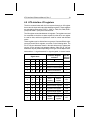
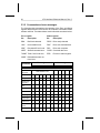
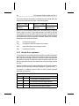
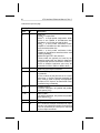
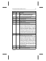
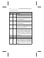
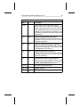
These registers can be divided into two groups: Command Block registers and Control Block registers, as shown in the following table. The
PC-AT I/O port addresses shown in the table below and in subsequent
text are for the primary host adapter address. Other PC-AT I/O port
addresses may be possible depending on the type of host adapter used.
Abbreviations: 1 = signal asserted; 0 = signal negated; X = doesn’t matter
Function / Register
selected
Signal name
CS1FX– CS3FX– DA2 DA1 DA0
DIOR–
DIOW–
PC-AT
I/O port
address
0
0
X
X
X
No operation
—
1
1
X
X
X
Invalid addressing
—
0
1
X
X
X
Selects Command Block
—
1
0
X
X
X
Select Control Block
—
Command Block registers
1
0
0
0
0
Data register
1
0
0
0
1
Error
register
Feature
register
1F1
1
0
0
1
0
Sector Count register
1F2
1
0
0
1
1
Sector Number register
1F3
1
0
1
0
0
Cylinder Low register
1F4
1
0
1
0
1
Cylinder High register
1F5
1
0
1
1
0
Drive/Head register
1F6
1
0
1
1
1
Status
register
Command
register
1F0
1F7