1
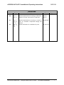
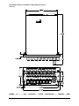
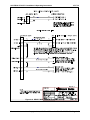
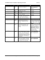
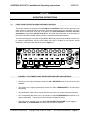
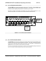
TM
ACCESS/A AUDIO CONTROL
SYSTEM
MODELS: A710 & A711
Installation and
Operating Instructions
TiL Document No.
96RE189
Rev. 2.2
July 2009
Technisonic Industries Limited
240 Traders Blvd. E., Mississauga, Ontario L4Z 1W7 Tel:(905)890-2113 Fax:(905)890-5338
www.til.ca
ACCESS/A A710/A711 Installation & Operating Instructions
96RE189
REVISIONS
Revision
Page
Description
Date
2.0
Sec. 1
Sec. 2
Modified specifications according to TSO tests.
Update to comply with results of TSO tests.
DEC 97
DEC 97
2.1
Sec. 1
Pg.1-6
& 1-7
Sec. 2
Pg. 216
Modified specifications according to results of
tests for increased Temperature Range and
Altitude.
Added clarification for installation kit parts.
04 MAY 98
2.2
Technisonic Industries ltd.
Copyright 1996, 97 BY TiL & SRC
Approved
08 JULY 09
ALL RIGHTS RESERVED
i
ACCESS/A A710/A711 Installation & Operating Instructions
96RE189
CAUTION
This unit contains static sensitive devices. Wear a grounded wrist strap and work at a static-safe
workstation when handling internal printed circuit boards.
WARRANTY INFORMATION
The Model A710 Audio Controller is under warranty for one year from date of purchase. Failed units
caused by defective parts or workmanship should be returned for warranty service to:
Technisonic Industries Limited
250 Watline Avenue
Mississauga, Ontario L4Z 1P4
Technisonic Industries Limited
3840 East Robinson Road, Suite 214
Amherst, New York 14228
Tel: (905) 890-2113
Fax: (905) 890-5338
Tel: (716) 691-0669
TRADEMARK INFORMATION
ACCESS/A, ACCESS/D, ACCESS/R & ACCESS/F are all trademarks of Technisonic Industries Ltd. and
Sphere Research Corporation. All rights reserved.
Technisonic Industries ltd.
Copyright 1996, 97 BY TiL & SRC
ALL RIGHTS RESERVED
ii
ACCESS/A A710/A711 Installation & Operating Instructions
96RE189
TABLE OF CONTENTS
TiL DOCUMENT
96RE189
SECTION 1
GENERAL DESCRIPTION
1.1
1.2
1.3
1.4
1.5
1.6
Introduction.................................................................................................................. 1-1
Description .................................................................................................................. 1-1
Purpose of Equipment................................................................................................. 1-2
Model Variations.......................................................................................................... 1-2
Technical Summary..................................................................................................... 1-5
System Limitations ...................................................................................................... 1-6
SECTION 2
INSTALLATION INSTRUCTIONS
2.1
2.2
2.3
2.4
2.5
2.6
2.7
2.8
2.9
2.10
2.11
2.12
2.13
2.14
2.15
General........................................................................................................................ 2-1
Equipment Packaging Log .......................................................................................... 2-1
Wiring Requirements................................................................................................... 2-1
Audio Panel Installation & Drawings ........................................................................... 2-1
Kit Contents .................................................................................................. 2-16
Pin Connections and Locations.................................................................... 2-17
Headphones ................................................................................................. 2-21
Microphones ................................................................................................. 2-21
PTT............................................................................................................... 2-21
Main Power .................................................................................................. 2-21
Backlighting Power....................................................................................... 2-22
Ground ......................................................................................................... 2-22
Storage ...................................................................................................................... 2-22
Post Installation Adjustment Locations ..................................................................... 2-23
Post Installation Adjustments .................................................................................... 2-24
SECTION 3
OPERATION
3.1
3.1.1
3.1.2
3.1.3
3.1.4
3.1.5
3.1.6
3.1.7
3.2
3.2.1
3.2.2
3.2.3
3.2.4
3.2.5
3.3
Front Panel Operator’s Switches & Controls............................................................... 3-1
Intercom Keying Mode & Sensitivity Control .................................................. 3-2
ICS or Intercom Volume Control .................................................................... 3-3
RX or Receive Volume Control ...................................................................... 3-3
RX or Receive Selectors ................................................................................ 3-4
TX or Transceiver Selectors........................................................................... 3-4
Emergency Switch Operation & Status LEDs ................................................ 3-5
A711 RX Monitor Level Controls.................................................................... 3-6
Special Signal Considerations .................................................................................... 3-7
Direct Audio Connections............................................................................... 3-7
Sum Node ...................................................................................................... 3-7
Alerting ........................................................................................................... 3-8
Voice Storage Function ................................................................................ 3-10
Speaker Audio.............................................................................................. 3-10
Changing Overlay Lighting & Radio Legends ........................................................... 3-11
Technisonic Industries ltd.
Copyright 1996, 97 BY TiL & SRC
ALL RIGHTS RESERVED
iii
ACCESS/A A710/A711 Installation & Operating Instructions
96RE189
LIST OF TABLES
1-1
1-2
A710 General Specifications.............................................................................................1-4
A711 General Specifications.............................................................................................1-5
LIST OF ILLUSTRATIONS
1-1
1-2
2-1A
2-1B
2-2
2-3
2-4
2-5
2-6
2-7
2-8
2-9
2-10
2-11
2-11
3-1
3-2
3-3
3-4
3-5
3-6
3-7
3-8
A710 Audio Control - General View..................................................................................1-3
A711 Audio Control - General View..................................................................................1-4
A710 Outline Drawing .......................................................................................................2-3
A711 Outline Drawing .......................................................................................................2-4
System Installation Drawings- Pilot/Co-Pilot Wiring.........................................................2-5
System Installation Drawings- COM1-COM4 Wiring .......................................................2-6
System Installation Drawings- COM5-NAV1 Wiring ........................................................2-7
System Installation Drawings- NAV2-NAV5 Wiring .........................................................2-8
System Installation Drawings- NAV6-NAV8/Tape Wiring................................................2-9
System Installation Drawings- Passenger Wiring ..........................................................2-10
System Installation Drawings- Alternate Passenger Wiring ..........................................2-11
System Installation Drawings- Power & Alerting Wiring ................................................2-12
System Installation Drawings- Direct Input/Special Function Wiring.............................2-13
System Installation Drawings- Reserved Wiring ............................................................2-14
System Installation Drawings- Special 6-Place Passenger Wiring................................2-15
Front Panel Operators Switches and Controls.................................................................3-1
ICS/Intercom Controls .......................................................................................................3-2
Level/Volume Controls ......................................................................................................3-3
RX & TX Selectors ............................................................................................................3-4
Status LEDs & Emergency Switch ...................................................................................3-5
A711 RX Monitor Level Controls ......................................................................................3-6
Overlay & Legend Insert .................................................................................................3-11
Removing the Overlay Assembly....................................................................................3-11
Technisonic Industries ltd.
Copyright 1996, 97 BY TiL & SRC
ALL RIGHTS RESERVED
iv
SECTION 1
GENERAL DESCRIPTION
1.1
INTRODUCTION
This publication provides operating and installation information on the Model A710 and A711,
ACCESS/A Audio Control series manufactured by Technisonic Industries Limited. This unit is
designed to provide high performance cockpit audio control in high noise installations. The unit is
plug and pin compatible with the ACCESS/A family format, to allow fleet wide compatibility with
all ACCESS/A installations. The A710 unit may be directly interchanged with an A711 in the
same harness, but the units are physically different in size, and the A711 has individual volume
controls for the transceiver inputs. Use of either of these boxes in an existing full stereo headset
installation, such as with an A720 or A721, would require the use of a headset output plug
adapter cable, although all other connections would be directly interchangeable.
1.2
DESCRIPTION
This high power audio controller delivers at least 332 mW of audio into 150 ohms at less than 2%
total distortion to the pilot and co-pilot positions simultaneously. It can deliver lower output powers
into 300 and 600 ohm headsets. The pilot’s position may also be internally strapped to interface
with 8-20 ohm headsets at the same power level. Push-button transmit selector switches allow
immediate selection of any of the seven supported aircraft communications transceivers or PA
amplifiers, while additional push-button audio input selector switches allow selection of any or all
of the supported transceivers and Nav aids. ACCESS/A systems have auto-RX switching when
a transmitter is selected, to reduce pilot workload and avoid operational problems.
Both the A711 and A710 have front panel selectable and adjustable VOX, LIVE or KEYED
intercom (ICS) functions. An EMERGENCY mode push-button switch (switch and LED turn redorange when activated) provides "straight through" or “fail-passive” transmit and receive audio for
the pilot on the selected communications channel. This switch also provides an implicit pilot
ISOLATION function, and allows the pilot to isolate himself from the co-pilot (and the ICS
system), so that he may access different communications from the other users supported by this
panel (in essence, an emergency link to the selected transceiver only). In the NORMAL position
(switch turns black & LED green), the pilot's audio is provided as selected by all of the panel
controls, and is part of the ICS system. Separate RX and ICS volume controls are provided on
the panel along with an ICS VOX threshold control. These units can also provide ICS support
and boom mic TX support for a complete aircraft crew, including the pilot, co-pilot, and up to 4-6
additional passengers.
A710 ACCESS/A INSTALLATION MANUAL
COPYRIGHT 1996 BY TiL & SRC
ALL RIGHTS RESERVED
Page 1-1
ACCESS/A A710/A711 Installation & Operating Instructions
96RE189
1.3
PURPOSE OF THE EQUIPMENT
The A710 and A711 ACCESS/A Audio Controls are designed to provide centralized audio
management and control within an airborne communications environment. This includes radio
and transceiver selection, intercom, airframe threat alerting, and crew management. These units
have been packaged to minimize size and weight characteristics and are ideally suited for
helicopter installations, or any other Dzus rail panel location. Both the A710 and A711 meet all of
the current requirements of US Forest Service "contractor furnished avionics" and can be used in
a dual control installation in conjunction with a TiL FM airborne transceiver to comply with all US
Forest Service Contract Requirements. These products are also compliant with TSO-C50c. The
units were tested according to RTCA/DO-214 and RTCA/DO-160C applicable categories with the
exception of the RF Susceptibility Test, which is based upon the requirements of RTCA/DO160A, and the Lightning Induced Transient Susceptibility Test which is not called out under
RTCA/DO-170.
1.4
MODEL VARIATION
The A710 and A711 come in two basic lighting configurations. A +28VDC panel lighting version
and a +5VDC panel lighting version. Operationally the two are identical. The color of the solidstate backlighting is green-yellow, at approximately 565nm wavelength. Panel front color may be
either Cessna Cadet gray or matte black. The default configuration is gray, with 28VDC
backlighting. Units may also be supplied with or without internal voice alerting modules. See the
ACCESS/A price list for model numbers and availability or different versions. The most common
variations are summarized below:
A710 = 961068 - (dash number)
A711 = 961072 - (dash number)
Dash Numbers:
-1
-2
-3
-4
Gray Panel
Black Panel
Gray Panel
Black Panel
special order:
-5
Gray Panel
-6
Black Panel
-7
Gray Panel
-8
Black Panel
Technisonic Industries ltd.
28VDC Lighting
28VDC Lighting
28VDC Lighting, includes A851 Voice Alerting
28VDC Lighting, includes A851 Voice Alerting
5VDC Lighting
5VDC Lighting
5VDC Lighting, includes A851 Voice Alerting
5VDC Lighting, includes A851 Voice Alerting
Copyright 1996, 97 BY TiL & SRC
ALL RIGHTS RESERVED
Page 1-2
ACCESS/A A710/A711 Installation & Operating Instructions
96RE189
Note: shows new case design (relocated Dzus fasteners) effective mid-1997.
Previous release case is identical except for this change (edge Dzus fasteners).
FIGURE 1-1 A710 ACCESS/A AUDIO CONTROLLER - GENERAL VIEW
Technisonic Industries ltd.
Copyright 1996, 97 BY TiL & SRC
ALL RIGHTS RESERVED
Page 1-3
ACCESS/A A710/A711 Installation & Operating Instructions
96RE189
FIGURE
1-2
A711
Technisonic Industries ltd.
ACCESS/A
AUDIO
CONTROLLER
Copyright 1996, 97 BY TiL & SRC
-
GENERAL
ALL RIGHTS RESERVED
VIEW
Page 1-4
ACCESS/A A710/A711 Installation & Operating Instructions
96RE189
1.5
TECHNICAL SUMMARY
A summary of the relevant electrical, operational, mechanical and physical characteristics of the
control panels are given in Table 1-1 and 1-2, General Specifications.
TABLE 1-1 A710 GENERAL SPECIFICATIONS
MODEL A710 - ACCESS/A Audio Controller:
PHYSICAL CHARACTERISTICS:
Width (max.) ........................................................................................................................ 5.75 inches
Height (max.) ..................................................................................................................... 1.875 inches
Depth ................................................................................................................................... 6.07 inches
Weight (including alerting).............................................................................................. 2.4lbs. (1.09Kg)
Mounting.......................................................................................................Standard Dzus, 4 fasteners
POWER SOURCE REQUIREMENTS:
DC Voltage (MIN, TYPICAL, MAX) ......................................................................... 20.0V, 28 V, 32.2V
(System performance will be degraded at upper and lower limits)
DC Current .............................................................................1 A (6 users @ 150 Ω, + speaker @ 8 Ω)
Backlighting Input:
Standard ................................................................................................................... 28 Vdc @ 50 mA
Optional .................................................................................................................... 5 Vdc @ 270 mA
TECHNICAL CHARACTERISTICS:
Input Impedance (Normal Mode, any RX input)......................................................... 1.55 k Ω (typical)
Input Impedance (Emergency Mode, Com1-7 RX Inputs) .......................... 50 Ω + Headset Z (typical)
Headset Channel Output Impedance...............................................8 or 80 Ω (depending on settings)
H/S Audio Power Output .................................................... at least 332 mW (primary user) into 150 Ω
with 6 headsets (150 Ω each) connected.
H/S Audio Power Output ................................................................ at least 500 mW (pilot) into 8-20 Ω
H/S Audio Power Output ...............................................at least 1500 mW (total) into 6 users @150 Ω
Speaker Power Output .......................................................................................at least 2.5 W into 8 Ω
Audio distortion (speaker or H/S) ................................ less than 2% THD @1kHz at total rated output
Audio Frequency Response (ICS) ................................................within 3 dB from 300 Hz to 6000 Hz
Audio Frequency Response (Rx & NAV) ......................................within 3 dB from 300 Hz to 3000 Hz
Hum and Noise Level ...................................................................... better than -60 dB below 500 mW
Input Muting (when mike is keyed)........................................................................................ adjustable
Input to Input isolation .................................................................... better than -70 dB between inputs
Deselected input isolation ........................................................................................ better than -65 dB
ENVIRONMENTAL:
Temperature (operating) ....................................................................................-45°C to +70° Celsius
Temperature (survival non-operating) ................................................................-55°C to +85° Celsius
Humidity............................................................................................................... 95% Non-condensing
Shock..............................................................................................................................12 g (any axis)
Altitude................................................................................................................................. 25,000 feet
Technisonic Industries ltd.
Copyright 1996, 97 BY TiL & SRC
ALL RIGHTS RESERVED
Page 1-5
ACCESS/A A710/A711 Installation & Operating Instructions
96RE189
TABLE 1-2 A711 GENERAL SPECIFICATIONS
MODEL A711 - ACCESS/A Audio Controller:
PHYSICAL CHARACTERISTICS:
Width (max.) ........................................................................................................................ 5.75 inches
Height (max.) ..................................................................................................................... 2.625 inches
Depth ................................................................................................................................... 6.07 inches
Weight (including alerting)............................................................................................ 3.0 lbs. (1.36 Kg)
Mounting.......................................................................................................Standard Dzus, 4 fasteners
POWER SOURCE REQUIREMENTS:
DC Voltage (MIN, TYPICAL, MAX) ........................................................................ 20.0V, 28 V, 32.2V
(System performance will be degraded at upper and lower limits)
DC Current ..............................................................................1 A (6 users @150 Ω, + speaker @8 Ω)
Backlighting Input:
Standard ................................................................................................................... 28 Vdc @ 70 mA
Optional .................................................................................................................... 5 Vdc @ 370 mA
TECHNICAL CHARACTERISTICS:
Input Impedance (Normal Mode, any RX input).................................................... 2K-1.5K Ω (approx.)
Input Impedance (Emergency Mode, Com1-7 RX Inputs) .......................... 50 Ω + Headset Z (typical)
Headset Channel Output Impedance...............................................8 or 80 Ω (depending on settings)
H/S Audio Power Output .................................................... at least 332 mW (primary user) into 150 Ω
with 6 headsets (150 Ω each) connected.
H/S Audio Power Output ................................................................ at least 500 mW (pilot) into 8-20 Ω
H/S Audio Power Output ...............................................at least 1500 mW (total) into 6 users @150 Ω
Speaker Power Output .......................................................................................at least 2.5 W into 8 Ω
Audio distortion (Speaker or H/S) ............................... less than 2% THD @1kHz at total rated output
Audio Frequency Response (ICS) ................................................within 3 dB from 300 Hz to 6000 Hz
Audio Frequency Response (Rx & NAV) ......................................within 3 dB from 300 Hz to 3000 Hz
Hum and Noise Level ...................................................................... better than -60 dB below 500 mW
Input Muting (when mike is keyed)........................................................................................ adjustable
Input to Input isolation .................................................................... better than -70 dB between inputs
Deselected input isolation ........................................................................................ better than -65 dB
ENVIRONMENTAL:
Temperature (operating) ....................................................................................-45°C to +70° Celsius
Temperature (survival non-operating) ................................................................-55°C to +85° Celsius
Humidity............................................................................................................... 95% Non-condensing
Shock..............................................................................................................................12 g (any axis)
Altitude................................................................................................................................. 25,000 feet
Technisonic Industries ltd.
Copyright 1996, 97 BY TiL & SRC
ALL RIGHTS RESERVED
Page 1-6
ACCESS/A A710/A711 Installation & Operating Instructions
96RE189
1.6
SYSTEM LIMITATIONS
A summary of the relevant system limitations is given below.
1.6.1
Power Limitations
With Standard Set-up, which consists of six headsets connected, a power output of not less than
332 mW is delivered per headset (as represented by 150 ohms) provided that the Direct Alert
Input is terminated in not less than 600 ohms and that nominal input voltages are applied
at the applicable channel inputs. Nominal microphone input: 100 mVrms; Nominal
Communications/Navigational Input: 5.5 Vrms.
1.6.2
Frequency Response Limitations
In accordance with the provisions made in RTCA/DO-214 Sections 2.8.1 and 1.5.1 the
communications transmit out and receiver channels (communications and navigational) possess
an effective bandwidth of 300 Hz--3000 Hz with a maximum amplitude variation of 3 dB within the
frequency range.
1.6.3
Crosstalk Limitations
To ensure that the crosstalk specifications are in accordance with the applicable sections of DO214, it is essential that 1) manufacturer’s maximum microphone input voltage of -4.7 dBu not
be exceeded in order to avoid jeopardising input to microphone output crosstalk results,
particularly at the low frequency end, 2) in the instance where only two access units are daisy
chained via their ICS tie-lines, a resistor of not greater than 600 ohms must be maintained
across the ICS tie-line in order to avoid jeopardising station to station crosstalk results in Rx
mode at the high frequency end.
The phenomenon of music appearing at the headset of the Second Station Panel (SSP or unit at
which the crosstalk is measured) for station to station crosstalk considerations is a limitation of
the A710/711 and for which crosstalk at high frequencies (6000 Hz and greater) can fall below 65
dB of attenuation. However music for most intents and purposes may be considered an optional
feature, which may be turned off without a negative impact on the essential functioning of the
access units.
Further, valid station to station crosstalk measurements were quoted in respect of a half power
level at the headset at the First Station Panel (FSP or unit from which the crosstalk originates) as
opposed to a half power level at the speaker output of the FSP because it is envisioned in the
latter scenario that the substantial speaker level (which will also necessitate very large signal
levels at the FSP headset) will have an impact on the listener at the SSP whether a crosstalk
signal appears at the SSP listener’s headset or not.
1.6.4 Isolation Limitations
Technisonic Industries ltd. Copyright 1996, 97 BY TiL & SRC
ALL RIGHTS RESERVED
Page 1-7
ACCESS/A A710/A711 Installation & Operating Instructions
96RE189
When in Pilot Isolation Mode, the pilot microphone for ICS operation is rendered inactive. Consequently,
neither co-pilot nor passengers can receive pilot intercom transmissions while the latter is in Isolation
mode.
1.6.5 Standard Settings Utilised Throughout Testing
Pilot Headset Settings utilised throughout testing was for the standard 150 ohms impedance headset.
The PAL options utilised were applicable to the following configuration: Where Pilot or Co-pilot
transmitted on the UUT ICS communication was possible only in the instance where the signal emanated
from other unit(s) daisy chained to the UUT via the ICS tie-line. In this event the UUT would receive the
ICS transmissions from the other unit(s). It was not possible for the UUT, which transmitted, to export ICS
communication to another unit nor was it possible for intra ICS communication to occur between users
connected to UUT (i.e. Option 1 not implemented).
1.6.6 Transmission Priority
Where Pilot and Co-pilot transmitted simultaneously the Pilot transmissions took precedence over those
of the Co-pilot. Co-pilot transmissions in this case would be rendered inactive.
1.6.7 Induced Signal Susceptibility, RF Susceptibility and RF Emission
The wiring connections called out in the Installation and Operating Instructions, chapter 2, describes
shield terminations for minimum ground loop noise. The test harnesses used for RTCA/DO-160 sections
19, 20, and 21 – Induced Signal Susceptibility, RF Susceptibility, and Emission of RF Energy respectively
- used shield terminations at both ends of the cable. Should RF susceptibility pose a problem in a
particular installation the installer may wish to try terminating shields at both ends of the cable, further, if
this does not produce satisfactory results then double shielding may be required.
Technisonic Industries ltd.
Copyright 1996, 97 BY TiL & SRC
ALL RIGHTS RESERVED
Page 1-8
ACCESS/A A710/A711 Installation & Operating Instructions
96RE189
SECTION 2
INSTALLATION INSTRUCTIONS
2.1
GENERAL
This section contains information and instructions for the correct installation of the A710 and
A711, ACCESS/A Audio Controllers.
Make certain that the unit is correctly operating in accordance with the equipment user's
requirements and manufacturer’s specifications, prior to releasing the equipment for service.
2.2
EQUIPMENT PACKING LOG
Unpack the equipment and check for any damage that may have occurred during transit. Save
the original shipping container for returns due to damage or warranty claims. Check that each
item on the packing slip has been shipped in the container. Verify that the equipment's
backlighting configuration is the same as that required.
2.3
WIRING REQUIREMENTS
Airframe wiring should be single conductor in accordance with MIL-W-22759 or multi-conductor in
accordance with MIL-C-27500 or Raychem 44 (81044) or 55 single or multi-conductor and
shielded wire. Heatshrink solder sleeves (such as Raychem or equivalent) should be utilized for
shield termination.
All Microphone audio input and output line connections should be made with 2 conductor/twisted
pair shielded cables as illustrated. Receiver audio input lines should also be 2 conductor twisted
pair shielded cables. The power and ground lines should be a minimum of #22 AWG (#20
preferred). Keying and all audio lines may be #24 AWG or larger.
CAUTIONS:
DO NOT bundle any low level audio lines with RF coaxial cables, 60 Hz or 400Hz AC
inverter, motor, pump or blower wiring, which can cause noise coupling between the various
systems, especially during RF transmission or pump/blower mechanical operation. Maintain as
much distance as possible from these types of wire bundles.
Note that there is really no effective field-installable shielding for magnetic coupling (which
occurs at high currents), and the only suitable prevention for this type of interference is distance
between the interfering lines. Shielded wiring is effective only for electrostatic coupling, or
voltage driven interference.
2.4
ACCESS/A AUDIO PANEL INSTALLATION
The A710 and A711 ACCESS/A Audio Controls are designed to be Dzus mounted and should
be installed in conjunction with an IN-A710 installation connector kit. See Figure 2-1 for an
outline drawing of the units with dimensions, to facilitate the installation.
Technisonic Industries ltd.
Copyright 1996, 97 BY TiL & SRC
ALL RIGHTS RESERVED
Page 2-1
ACCESS/A A710/A711 Installation & Operating Instructions
96RE189
CABLE CLEARANCE:
Allow at least 2.5” of additional rear clearance for mating connectors and hoods (side routing),
or 3.0” (back routing). Cables should be long enough to permit the unit to be removed from the
panel, and the connectors to be easily disengaged. DO NOT dress or strap the mating cables so
that front removal is impossible, or the unit cannot be removed for service or adjustment in the
field.
ALERT OPERATION:
Voice alerting can be supplied with this unit from the factory (addition of an A850, A851 or A852
module and resulting dash number change), or it can be added in the field. Field installation must
be done at a fully equipped service bench, and requires a system functional test & recertification.
PANEL MODIFICATIONS:
Modified panel legends, panel lighting, NVG compatibility, or overlay colors are also
possible, please see the price list for a full summary of options and part numbers. Overlays and
legends may be easily changed at low cost in the field with no special tools or service facilities
required.
SHIELD GROUNDS:
Convenient shield ground connections are provided at each connector for the indicated input
signal shield drains, and will give the shortest possible return for these lines. These shield lines
may be daisy chained together, and a single wire from each cable brought out to the connector
pin .
INTERNAL OPTIONS:
All configurable and variable options of the A710 and A711 (pilot H/S impedance, muting logic,
included speaker audio lines, etc.) can be set or changed simply by altering internal jumpers, but
these changes require opening the unit for access to the required connections.
DRAWINGS:
A full ACCESS/A (mono) system installation example is given in the multi-page sections of
Figure 2-x. These installation and mechanical drawings are available as AutoCAD files
(“DWG”/R12 format, Windows Metafile “WMF” or “DXF” format) free of charge to authorized TiL
dealers and completion centers.
Technisonic Industries ltd.
Copyright 1996, 97 BY TiL & SRC
ALL RIGHTS RESERVED
Page 2-2
ACCESS/A A710/A711 Installation & Operating Instructions
FIGURE 2-1A
Technisonic Industries ltd.
96RE189
Outline Drawing for Model A710 ACCESS/A Audio Controller
Copyright 1996, 97 BY TiL & SRC
ALL RIGHTS RESERVED
Page 2-3
ACCESS/A A710/A711 Installation & Operating Instructions
FIGURE 2-1B
Technisonic Industries ltd.
96RE189
Outline Drawing for Model A711 ACCESS/A Audio Controller
Copyright 1996, 97 BY TiL & SRC
ALL RIGHTS RESERVED
Page 2-4
ACCESS/A A710/A711 Installation & Operating Instructions
96RE189
Figure 2-2 PILOT/CO-PILOT WIRING
Technisonic Industries ltd.
Copyright 1996, 97 BY TiL & SRC
ALL RIGHTS RESERVED
Page 2-5
ACCESS/A A710/A711 Installation & Operating Instructions
96RE189
Figure 2.3 COM1-COM4 WIRING
Technisonic Industries ltd.
Copyright 1996, 97 BY TiL & SRC
ALL RIGHTS RESERVED
Page 2-6
ACCESS/A A710/A711 Installation & Operating Instructions
96RE189
Figure 2-4 COM5-NAV1 WIRING
Technisonic Industries ltd.
Copyright 1996, 97 BY TiL & SRC
ALL RIGHTS RESERVED
Page 2-7
ACCESS/A A710/A711 Installation & Operating Instructions
96RE189
Figure 2-5 NAV2-NAV5 WIRING
Technisonic Industries ltd.
Copyright 1996, 97 BY TiL & SRC
ALL RIGHTS RESERVED
Page 2-8
ACCESS/A A710/A711 Installation & Operating Instructions
96RE189
Figure 2-6 NAV6-NAV8/TAPE WIRING
Technisonic Industries ltd.
Copyright 1996, 97 BY TiL & SRC
ALL RIGHTS RESERVED
Page 2-9
ACCESS/A A710/A711 Installation & Operating Instructions
96RE189
Figure 2-7 PASSENGER WIRING
Technisonic Industries ltd.
Copyright 1996, 97 BY TiL & SRC
ALL RIGHTS RESERVED
Page 2-10
ACCESS/A A710/A711 Installation & Operating Instructions
96RE189
Figure 2-8 ALTERNATE PASSENGER WIRING
Technisonic Industries ltd.
Copyright 1996, 97 BY TiL & SRC
ALL RIGHTS RESERVED
Page 2-11
ACCESS/A A710/A711 Installation & Operating Instructions
96RE189
Figure 2-9 POWER & ALERTING WIRING
Technisonic Industries ltd.
Copyright 1996, 97 BY TiL & SRC
ALL RIGHTS RESERVED
Page 2-12
ACCESS/A A710/A711 Installation & Operating Instructions
96RE189
Figure 2-10 DIRECT INPUT/SPECIAL FUNCTION WIRING
Technisonic Industries ltd.
Copyright 1996, 97 BY TiL & SRC
ALL RIGHTS RESERVED
Page 2-13
ACCESS/A A710/A711 Installation & Operating Instructions
96RE189
Figure 2-11 RESERVED WIRING
Technisonic Industries ltd.
Copyright 1996, 97 BY TiL & SRC
ALL RIGHTS RESERVED
Page 2-14
ACCESS/A A710/A711 Installation & Operating Instructions
96RE189
Figure 2-12 SPECIAL 6-PLACE PASSENGER WIRING
Technisonic Industries ltd.
Copyright 1996, 97 BY TiL & SRC
ALL RIGHTS RESERVED
Page 2-15
ACCESS/A A710/A711 Installation & Operating Instructions
2.5
96RE189
INSTALLATION KIT - CONTENTS
The IN-A710 installation kit (used for both A710 & A711 units) consists of:
1.
One 50 pin female D-subminiature mating connector complete with crimp
pins, V-locks and hood. (DD50S)
P101
Positronics p/n SD50F00JVLX + 50ea. FC7520D contacts or equiv.
2.
One 37 pin female D-subminiature mating connector complete with crimp
pins, V-locks and hood. (DC37S)
P201
Positronics p/n SD37F00JVLX + 37ea. FC7520D contacts or equiv.
3.
One 15 pin female D-subminiature mating connector complete with crimp
pins, V-locks and hood. (DA15S)
P102
Positronics p/n SD15F00JVLX + 15ea. FC7520D contacts or equiv.
4.
One 15 pin male D-subminiature mating connector complete with crimp
pins, V-locks and hood. (DA15P)
P202
Positronics p/n SD15M00JVLZ (or JVLX) + 15ea. MC7520D contacts or equiv.
Note: The mating connectors use a “one-hand”, tool-free Positronics V-lock assembly for ease of
airframe installation and removal.
To match approved installation agency standard practices, equivalent machined contact Dsubminiature connectors from vendors such as AMP/Tyco, Cannon, Cinch, or Positronics, or
those which are directly compatible with MIL-DTL-24308 may be substituted for the Positronics
contacts and inserts shown, but the Positronics V-latch lock and hood must be retained in the
final assembly for proper attachment to the A710/711 unit. Any crimp contact used must be
installed with the proper crimping die, set to the correct wire size, and a pull test should be
done on every wire after assembly. Solder contact versions of the D-subminiature family from
the above suppliers may also be used, if every wire/contact junction is individually heat-shrink
sleeved during assembly to prevent inter-contact shorts within the hood.
In addition, the following items are packed with each A710 unit:
1.
This manual.
2.
Warranty registration card.
Technisonic Industries ltd.
Copyright 1996, 97 BY TiL & SRC
ALL RIGHTS RESERVED
Page 2-16
ACCESS/A A710/A711 Installation & Operating Instructions
2.6
96RE189
INSTALLATION - PIN LOCATIONS AND CONNECTIONS
The pin numbers and locations for the connectors located on the rear of the A710/A711 ACCESS/A
Audio Control are shown in the following tables.
Mating Cable Connector: DD50S
Bottom Connector J101 DD50P
(50 pin Female)
J101 TX Connector Pin Assignments
Com
34
35
36
37
38
39
Mic
Key
1
2
3
4
5
Connection
Power GROUND
PAX 1 Mic In
PAX 2 Mic In
PAX 3 Mic In
PAX 4 Mic In
PAX 5 Mic In
Lighting/Dimmer Common (GND)
+5VDC Dimmer Input
+28VDC Dimmer Input
Supplemental Control Line
Reserved Control Line
Key
6
7
8
9
26
Connection
Pilot’s Mic In
Co-Pilot’s Mic In
Hand Mic In
Pilot’s ICS Key
C-Pilot’s ICS Key
18
19
20
21
22
Com
40
41
42
Mic
23
24
25
43
44
45
46
47
48
49
50
27
28
29
30
31
32
33
ACCESS/A System
Notes
Main Power Ground Line
Dimmer Lines
Dimmer Lines
Use only one
Dimmer Lines
Use only one
Default = PAX ICS PTT Default = speaker volume.
Notes
Emergency Hand Mic
Active when grounded
Active when grounded
Shield ground for mic lines
10
COM 7/PA TX Mic Out
11
COM 6 TX Mic Out
12
COM 5 TX Mic Out
13
COM 4 TX Mic Out
14
COM 3 TX Mic Out
15
COM 2 TX Mic Out
16
COM 1 TX Mic Out
17
+28VDC Power In
Main Power Input
Grounding PAX ICS PTT line (Pin 4) will make the passenger headsets LIVE, if use of a drop cord is
desired that interrupts mic line to enable PAX ICS. Alternately, this line may be keyed by the drop cord to
enable ICS, or no drop cord can be used, and the front panel VOX control can guide all ICS operation.
View from solder side of MATING CABLE CONNECTOR DD50S:
1...................................17
18............................33
34.................................50
Technisonic Industries ltd.
Copyright 1996, 97 BY TiL & SRC
ALL RIGHTS RESERVED
Page 2-17
ACCESS/A A710/A711 Installation & Operating Instructions
96RE189
Mating Cable Connector: DC37S
Top Connector J201 DC37P
(37 Pin Female)
J201
Low
High
Connector Pin Assignments
Connection
RX Connector
Notes
20
21
1
2
ICS Node
SUM Node Input
22
4
23
3
24
6
25
26
27
28
29
30
7
8
9
10
11
12
Direct Input
Shield ground
Music R Audio (supports BRIDGE
OUTPUT!)
Music L Audio (supports BRIDGE
OUTPUT!)
NAV 6 RX Audio
NAV 5 RX Audio
NAV 4 RX Audio
NAV 3 RX Audio
NAV 2 RX Audio
NAV 1 RX Audio
31
13
COM 7 RX Audio
ICS Tie Line Between Units
For connection to A770
expansion units only
Unswitched Direct Input
Shield drain for input lines.
Switch #4: Pin 23 is common
Right-hand-most RX switch.
Switch #4: Pin 24 is common
Right-hand-most RX switch.
Switch #3
Switch #3
Switch #2
Switch #2
Switch #1
Switch #1 Left-hand-most RX
switch
Not Used If PA Enabled. Can also
be strapped “ON” internally.
Right-hand-most TX switch.
32
33
34
35
36
37
14
15
16
17
18
19
COM 6 RX Audio
COM 5 RX Audio
COM 4 RX Audio
COM 3 RX Audio
COM 2 RX Audio
COM 1 RX Audio
5
Common Lines
Common Lines
Left-hand-most TX switch
Floating above airframe ground in ACCESS systems, but serves as
common signal low for corresponding input signal lines.
Floating above airframe ground in ACCESS systems, and not
connected to any other common line in the system.
View from solder side of DC37S MATING CONNECTOR:
1...................................19
20............................37
Technisonic Industries ltd.
Copyright 1996, 97 BY TiL & SRC
ALL RIGHTS RESERVED
Page 2-18
ACCESS/A A710/A711 Installation & Operating Instructions
96RE189
Mating Cable Connector: DA15P
Top Connector J202 DA15S
(15 Pin Male)
Note: this is the only male cable connector on the control
J202
Low
Hi
Connector Pin Assignments
Connection
Headset Connector
Notes
9
1
Pilot’s H/S Audio
10
2
Direct Alert Connection
11
3
4
5
12
13
Co-Pilot’s H/S Audio
PAX 1 H/S Audio
PAX 2 H/S Audio
PAX 3 H/S Audio
PAX 4 H/S Audio
PAX H/S Common
PAX H/S Common
Speaker Output
Shield Ground
Can be set internally to either 8/20
or 150/600
High level headset direct audio (via
pad)
Group A
Group A
Group B
Group A
Group B
6
14
15
7
8
8 Ohms min.
For connection to external floating
shields
PAX Headset lines from the same GROUP may be connected in parallel to give more drive for a rear
headset bus, but then must have isolation safety resistors installed (~47-51ohms) in series with the
rear headsets for accidental short circuit isolation. See installation drawings for full details.
Common Lines
Common Lines
Floating above airframe ground in ACCESS systems, but serves as
common signal low for corresponding output signal lines only.
At Ground potential, but line must be connected here only, not to
airframe.
View from solder side of DA15P MATING CONNECTOR:
8....................................1
15...........................9
Technisonic Industries ltd.
Copyright 1996, 97 BY TiL & SRC
ALL RIGHTS RESERVED
Page 2-19
ACCESS/A A710/A711 Installation & Operating Instructions
96RE189
Mating Cable Connector: DA15S
Bottom Connector J102 DA15P
(15 Pin Female)
J102
Low
High
1
Connector Pin Assignments
Connection
Play
2
3
Reset
CTS
4
5
6
7
Data
Audio In
Audio Out
+28VDC In
8
These lines used only by the
remote computer programmer
to create new alerting functions.
Not connected in the airframe.
Ground (Power)
9
Record
10
Alert 6 (in)
11
Alert 5 (in)
12
Alert 4 (in)
13
Alert 3 (in)
14
Alert 2 (in)
15
Alert 1 (in)
Programming Lines
Alerting Connector
Notes
Ground externally to activate
last message replay function.
Alert Power (may come from
existing alert breaker)
Power ground return
connection.
Ground externally to activate
record function.
Active when grounded. Accepts
+28VDC.
Active when grounded. Accepts
+28VDC.
Active when grounded. Accepts
+28VDC.
Active when grounded. Accepts
+28VDC.
Active when grounded. Accepts
+28VDC.
Active when grounded. Accepts
+28VDC.
Reserved for programming functions, do not use in the airframe.
Alerting may be either true voice, speech based alerting, or tone coded alerting, as specified by the
installed alerting module.
Alerting has separate power and ground connections, unrelated to the rest of the audio system. Power
may be taken from an existing alerting breaker, to retain the alerting defeat function by pulling one
common breaker. Power consumption is very low, typically under 25mA.
Programming for both tones and true voice alerting is done with a PC, and a special TiL programming
fixture. Contact TiL for full details.
View from solder side of DB15S MATING CONNECTOR:
1....................................8
9...........................15
Technisonic Industries ltd.
Copyright 1996, 97 BY TiL & SRC
ALL RIGHTS RESERVED
Page 2-20
ACCESS/A A710/A711 Installation & Operating Instructions
2.7
96RE189
HEADPHONE INSTALLATION
The A710 & A711 ACCESS/A Audio Controls are intended for use with industry standard 150/600
ohm headphones. There is also provision for connection to an 8 ohm (minimum impedance)
speaker, for a supplemental cabin speaker output. The pilot’s headset (only) may also be strapped
internally for a standard low impedance headset (8-20 ohms) at the same power level.
In all cases, the headset lines should be run as shielded, twisted pairs, to avoid contamination
(and resulting cross-talk) of companion low level mic lines or audio input lines. Failure to follow this
wiring guideline will result in unwanted cross-talk, and phantom audio that will appear to be transmit
or intercom related.
The use of high quality headsets and “carbon-equivalent” boom microphones, such as David Clark
or Bose is strongly recommended. Mixed headset impedances within the same ship will give
differing volume levels at the same A710/A711 control settings. The use of headsets with
individual volume controls is very useful to permit level adjustment suitable to each position,
due to differing headsets and the inevitable different hearing capability of individual users.
2.8
MICROPHONE INSTALLATION
All microphone connections to the A710 or A711 must be done with shielded cables. The inputs
are intended for use with standard “carbon-equivalent” or amplified dynamic Microphones (such as
the D/C M1, M4 M7, etc.). Shielded, twisted pair routing is strongly preferred for lowest noise
pick-up, but single conductor shielded wiring generally gives adequate results in non-critical or
single box installations, although noise floor and cross-talk will increase.
2.9
PTT CONNECTIONS
The Pilot, Co-pilot and hand microphones require a PTT (Push To Talk) button or switch to key the
transceivers as required. If a Hand-held microphone is used, tie the PTT button to the appropriate
key line. If a boom microphone is incorporated into the headset, an external switch, such as the
cyclic switch or yoke switch, will be required to key the transmitter. PTT lines should go directly to
ground to activate the desired key function.
2.10
MAIN POWER +28VDC
The main power +28VDC (±20%) is connected to pin 17 of the 50 pin (lower) "D"
connector.
As previously indicated, this connection should be made with at least #22 AWG wire, with #20
preferred. If from a very noisy source, with high levels of parasitic AC, shielding may improve
rejection of this coupled AC into other low level audio lines.
Technisonic Industries ltd.
Copyright 1996, 97 BY TiL & SRC
ALL RIGHTS RESERVED
Page 2-21
ACCESS/A A710/A711 Installation & Operating Instructions
2.11
96RE189
BACKLIGHTING POWER +28VDC / +5VDC
The backlighting power for the front panel of the A710 and A711 is supplied via pins 1, 2 & 3 of the
50 pin (lower) "D" connector. Unless ordered and indicated otherwise on the rear of the ACCESS/A
A710, the unit is shipped with the +28VDC backlighting option. Note that different pins are used for
5V and 28V lighting, and there is a dedicated lighting ground pin, which MUST be connected for the
lighting to work. Lighting is isolated from other circuits in the system for noise reduction reasons.
2.12
GROUND
The A710 Audio Control is designed for full Ground Isolation from the Airframe. This is necessary
in many cases where the Airframe Ground causes significant noise in the Audio system.
Main ground (power return) to the A710 and A711 is on pin 34 of the 50 pin "D" connector. All other
groups of audio lines have their own “common” lines, which float above the airframe ground, to
provide signal isolation. These common lines MUST be connected to the source audio, or no signal
flow will result, except for stray leakage.
2.13
STORAGE
When not in use, Store the A710 and A711 in the original Anti-Static bag if possible, and in a nonHumid place. Optimum storage temperatures for best shelf life should not exceed +35°C, or be less
than -10°C.
Technisonic Industries ltd.
Copyright 1996, 97 BY TiL & SRC
ALL RIGHTS RESERVED
Page 2-22
ACCESS/A A710/A711 Installation & Operating Instructions
96RE189
A710 Adjustment Locations
2.14
POST-INSTALLATION ADJUSTMENT LOCATIONS
A711 Adjustment Locations
Technisonic Industries ltd.
Copyright 1996, 97 BY TiL & SRC
ALL RIGHTS RESERVED
Page 2-23
ACCESS/A A710/A711 Installation & Operating Instructions
2.15
96RE189
POST-INSTALLATION ADJUSTMENTS
After installation, the A710 and A711 may require adjustment of some functions to compensate for
airframe and equipment specific issues, and to suit user tastes. Locations of these adjustments are
as shown in section 2.14, and are essentially identical for both units. All are 20-turn miniature
trimpots, except as noted. “TAPE” input may be for any entertainment audio feed, such as CD,
tuner, etc.
Note, back adjustments (alerting) are NOT normally field adjusted, unless required. The 37
Pin connector (not required) above these adjustments may be removed to facilitate the
adjustment of these alerting pots. Be extremely careful of any adjustments to these
settings, as incorrect levels will be highly problematic in the airframe. These are normally
bench adjustments.
The unit adjustments are as follows:
Adjustment Name
Direct Input Level
Location
Top
Procedure/purpose
Adjusts “Direct” input J210-3/22, an
un-switched input, set as required.
Often not used in installation.
Notes
Preset, Set to desired level,
if required
Voice Alerting Input
Level
Back
Voice Alerting Output
Level
Back
Adj. for comfortable voice recording
level (record key pressed for
sample, then playback to listen)
Adj. for comfortable alert playback
level (activate any alert), and voice
recording playback level.
Too sensitive will
increase noise floor. Not
normally a field setting.
Too high will be
disruptive for pilot. Too low
will kill the voice alerting.
Adjust with CAUTION! Not
normally a field setting.
ICS Low Cut
R/H Side
Not normally a field setting.
TAPE Hi Cut
R/H Side
TAPE Low Cut
R/H Side
TAPE Mute Depth
R/H Side
TAPE Volume
R/H Side
Sets low frequency cut-off (BASS)
of ICS audio. Useful for removing
very high levels of cabin low
frequency noise on the intercom.
Sets high frequency cut-off
(TREBLE) of TAPE audio.
Sets low frequency cut-off (BASS)
of TAPE audio.
Sets muting level of TAPE audio
during ICS or TX operations. May
be muted completely OFF, or set to
a lower level during these
operations.
Sets sensitivity of the TAPE audio
input channels. Note that this input
is NOT set by the front panel RX
control.
Technisonic Industries ltd.
Copyright 1996, 97 BY TiL & SRC
Preset, Set to desired level,
if required
Preset, Set to desired level,
if required
Preset to OFF, Set to other
desired level, if required
Preset, Set to desired level,
if required for specific
system. Do not make too
sensitive, or noise floor will
suffer
ALL RIGHTS RESERVED
Page 2-24
ACCESS/A A710/A711 Installation & Operating Instructions
96RE189
Adjustment Name
RX Mute Depth
Location
L/H Side
Upper
Procedure/purpose
Sets mute level of RX audio during
TX operations. (Sidetone)
RX Hi Cut
L/H Side
Upper
L/H Side
Upper
L/H Side
Upper
L/H Side
Upper
Sets high frequency cut-off
(TREBLE) of RX audio.
Sets low frequency cut-off (BASS)
of RX audio.
Sets Mute depth of ICS audio
during TX operations
Sets hi frequency cut-off (TREBLE)
of ICS audio. Useful for removing
very high levels of cabin high
frequency noise on the intercom.
ICS Talk Level
L/H Side
Lower
Sets ICS talk level, and audio
exported to other units in the
airframe. Normally set to midposition.
TX Mic Level
L/H Side
Lower
Sets TX Mic level, and audio
exported to transceivers in the
airframe. Normally set to midposition.
PAX VOX Trip
L/H Side
Lower
VOX Delay
L/H Side
Lower
Sets VOX offset for passengers.
Allows for differing Mics or ambient
conditions. PAX VOX tracks front
panel VOX control, but is offset by
this adjustment, which can be more
or less sensitive. Normally set to
mid-position.
Sets time dwell or delay of VOX
circuit, once activated. Too short
will result in choppy VOX operation,
too long will allow VOX to remain
open when no voice is present.
RX Low Cut
ICS Mute Depth
ICS Hi Cut
Technisonic Industries ltd.
Copyright 1996, 97 BY TiL & SRC
Notes
Preset for 6dB at midvolume control. Set to
other desired level, if
required
Preset, Set to desired level,
if required
Preset, Set to desired level,
if required
Preset, Set to desired level,
if required
Preset, Set to desired level,
if required
Single -turn pot. Should
be set to lowest level that is
acceptable, to reduce ICS
noise. Normally set to midposition.
Single -turn pot. Should
be set to lowest level that is
acceptable, to reduce TX
mic noise. Normally set to
mid-position. Should be
similar to level from pilot’s
Mic output during
emergency operation.
Single -turn pot. Should
be set to mid-position
unless change required.
Single -turn pot. Should
be set to mid-position
unless change required.
ALL RIGHTS RESERVED
Page 2-25
ACCESS/A A710/A711 Installation & Operating Instructions
96RE189
Unit modifications that can be set in the field during installation:
Internal, removable jumpers may be set for the following items (DEFAULT is BOLD):
Main RX Board
PILOT HEADSET Impedance:
150/600 or 8/20 ohms
SPEAKER AUDIO:
RX Audio
TAPE Audio
ON/OFF
ON/OFF
HEADSET AUDIO:
TAPE Audio
ON/OFF
RX VOL MIIN:
Set to 5% or Set to 0%
Internal, removable jumpers may be set for the following items (DEFAULT is BOLD):
Mic Processor Board
PAL OPT 1:
Jumpered
PAL OPT 2:
Jumpered
OPT 3 (Pil. TX Muting)
Jumpered
The following has a solderable jumper:
Main RX Board
COM7 RX Audio
Technisonic Industries ltd.
Set On, Set Switched, Set OFF
Copyright 1996, 97 BY TiL & SRC
ALL RIGHTS RESERVED
Page 2-26
ACCESS/A A710/A711 Installation & Operating Instructions
96RE189
SECTION 3
OPERATING INSTRUCTIONS
3.1
FRONT PANEL OPERATORS SWITCHES AND CONTROLS
This section explains the operation of the A710 & A711 ACCESS/A Audio Controls, and how to use
either system in a typical aircraft environment. Since the controls on the two units differ only in the
extra receive monitor pots at the top of the A711, the A710 illustration is used for all of the
explanations, except those specific to the A711. All normal user controls are on the front panel of
the unit and are either variable rotating controls, or selectable push-button switches.
The exact radio legends on the face of the A710 or A711 may vary from the illustration shown, due
to customer specifications, and the final legend insert that is installed for the specific aircraft
installation. A full view of the controls is given in Figure 3-1.
FIGURE 3-1 A710 FRONT PANEL OPERATOR'S SWITCHES AND CONTROLS
•
The top row of round push-buttons selects the RX or RECEIVER audio to be sent to the crew
headsets.
•
The bottom row of square push-buttons selects the TX or TRANSCEIVER to be used when
transmitting.
•
Any combination of RX sources may be selected at one time, for system monitoring purposes.
•
The corresponding RX audio of any TX selection is made AUTOMATICALLY whenever a TX
button is depressed. This function is often referred to as Auto-RX select.
•
The knobs at the right side of the unit adjust ICS VOLUME, RX VOLUME, and the trigger or
VOX LEVEL of the INTERCOM, as well as its exact mode of operation.
Technisonic Industries ltd.
Copyright 1996, 97 BY TiL & SRC
ALL RIGHTS RESERVED
Page 3-1
ACCESS/A A710/A711 Installation & Operating Instructions
3.1.1
96RE189
INTERCOM KEYING MODE AND SENSITIVITY CONTROL
This adjustment selects how the intercom will activate. In the VOX (Voice Activated) mode, the
audio produced by any of the microphones will break the squelch of the intercom and the audio will
be routed through the system. The threshold audio level required to break the squelch is adjusted
by this knob. Turning the knob more clockwise makes the system more sensitive to incoming mic
audio. A fully clockwise setting on the knob will leave the intercom on at all times, giving LIVE or
HOT MIC operation. When set fully counter-clockwise, in the switch detent position, the intercom
is in the KEYED mode, will only produce audio when the intercom PTT line is keyed.
While the co-pilot, pilot and passengers have individual mic VOX gates (3 in total), they are
controlled from a common front panel control. Individual gating reduces the amount of unwanted
noise when the intercom is triggered, and makes intercom communication more intelligible as a
result. The passengers may have their VOX threshold offset by an internal adjustment (PAX VOX)
to accommodate differing headset types or ambient noise conditions.
With only a single A710 or A711 control, best operation of all ICS functions is obtained when the
microphones are all of the same type (or have very similar characteristics). Headsets with
significantly different microphones or earpiece efficiencies make it difficult to achieve satisfactory
control adjustments for all users, unless they also have individual level controls. Good quality
headsets, such as David Clark, Telex or Bose, with noise reducing, amplified dynamic microphones
and individual headset volume controls, give the most effective and user-adjustable performance,
and minimal system difficulties. Use of “clone” headsets that visually resemble these higher quality
units, but have much poorer electrical and acoustic performance is strongly discouraged, as the
entire system operation will suffer. This is especially true under high noise conditions or continuous
rough use. Marginal headsets will compromise the ship’s entire audio system.
Full CCW:
Keyed ICS/PTT
Full CW:
Live/HOT Mic
VOX
CONTROL
FIGURE 3-2 A710 ICS/INTERCOM CONTROLS
Technisonic Industries ltd.
Copyright 1996, 97 BY TiL & SRC
ALL RIGHTS RESERVED
Page 3-2
ACCESS/A A710/A711 Installation & Operating Instructions
3.1.2
96RE189
ICS or INTERCOM VOLUME CONTROL
The ICS LEVEL knob controls the intercom volume level for all users. Fully clockwise is the
maximum volume level and counter-clockwise the minimum. The ICS volume can be set to zero,
but has the internal capability to be preset to a low minimum value, if desired.
ICS audio is normally muted during TX operations, but may be adjusted internally for a user
specified muting depth, or the muting function may be disabled by jumper selection.
ICS LEVEL
CONTROL
(inner)
RX LEVEL
CONTROL
(outer)
FIGURE 3-3 A710 LEVEL/VOLUME CONTROLS
3.1.3
RX or RECEIVE VOLUME CONTROL
The RX LEVEL knob controls the volume level of all the system receivers. Fully clockwise is the
maximum volume level, and counter-clockwise the minimum. RX audio is derived from both the
receivers (such as Nav aids) and the transceivers (Comms, etc.) in the system. The RX audio level
cannot be set to zero, and has an internal minimum level setting.
RX audio is normally partially muted during TX operations, and is adjustable internally to the desired
level for TX sidetone. Note that sidetone must come from the radio itself.
Technisonic Industries ltd.
Copyright 1996, 97 BY TiL & SRC
ALL RIGHTS RESERVED
Page 3-3
ACCESS/A A710/A711 Installation & Operating Instructions
3.1.4
96RE189
RX or RECEIVE SELECTORS
These 10 push-button RX SELECTOR switches allow the crew to monitor any combination of the
Receivers in the airframe system, independent of the setting of the transceiver selectors. The RX
SELECTORS have an alternate action, push in to activate the audio, push again to have the
switch return to the out position and off.
Any number or combination of RX switches may be used at the same time. Note that the
corresponding RX audio is always automatically selected by a TX SELECTOR, and the matching
RX switch does not have to be selected as well. Com 7 (also the PA position) does not have a
separate RX monitor switch; its audio is turned on only when the TX selector for COM7is
pushed.
RX MONITOR
SWITCHES
STATUS
INDICATOR LED
TX SELECT
SWITCHES
FIGURE 3-4 A710 RX & TX SELECTORS
3.1.5
TX or TRANSCEIVER SELECTORS
The setting of the TX SELECTOR switches determines which Transceiver will transmit the
activated microphone audio, and which receiver the system will monitor, independent of the
additional RX switch settings. The buttons have an interlocking action, and pressing one button
will automatically de-select any other that is already activated. If two buttons are depressed at the
same time, simulcast operation (on two radios) is enabled.
The buttons change from black to white when activated, and a corresponding STATUS LED
illuminates green above the button. If a PA is installed, the button itself turns yellow to warn of
potential live broadcast of audio outside the aircraft. The LEDs turn yellow when the specific
transmitter is activated by the A710/711, and all the LEDs will extinguish if all transmitter buttons
are returned out to the off (black) position, and no transmitter has been selected. This indicates that
no valid TX mode has been selected by the crew.
In the EMERGENCY MODE, the radio(s) selected by this group of switches is sent directly to the
pilot’s headset, bypassing all of the internal power amplifiers and other electronics.
Technisonic Industries ltd.
Copyright 1996, 97 BY TiL & SRC
ALL RIGHTS RESERVED
Page 3-4
ACCESS/A A710/A711 Installation & Operating Instructions
3.1.6
96RE189
EMERGENCY SWITCH OPERATION & STATUS LEDs
The operation of the A710 control can be changed from NORMAL to EMERGENCY operation in
two different ways. First, if DC power fails to the unit, the internal auto-emergency function is
enabled, which transfers the unit to a passive emergency mode to enable critical communication to
continue for the pilot. This auto-switch-over is indicated by all STATUS LEDs going black
(including the one over the emergency switch).
Second, the PILOT EMERGENCY SWITCH can be depressed, (alternate action), which will force
this transfer. In this mode, the STATUS LED above the switch changes from green to deep
orange, and the button itself turns orange.
In either case, the PILOT (or primary user of the control) is connected directly to the radio that
has been selected by the TX SELECTOR switch. Boom Mic Transmit operates normally, as does
receive, but the headset power level is reduced to the passive (un-amplified) radio level. All internal
electronics are bypassed for the pilot, which permits some level of operation even with massive
equipment failure or loss of power.
When the pilot emergency switch is used to shift to emergency operation, the other users of the
control are essentially un-affected, and continue to operate on the ICS & music circuit. This mode
may also be used as a “Pilot Isolate” function, as all radio audio is disabled to the passengers,
and only the tape and ICS audio remain.
STATUS
INDICATOR LED
EMERGENCY
SWITCH
FIGURE 3-5 A710 STATUS LEDs & EMERGENCY SWITCH
Technisonic Industries ltd.
Copyright 1996, 97 BY TiL & SRC
ALL RIGHTS RESERVED
Page 3-5
ACCESS/A A710/A711 Installation & Operating Instructions
3.1.7
96RE189
A711 RX MONITOR LEVEL CONTROLS
The operation of the A711 control differs slightly from the A710, in that individual receive monitor
th
controls are provided to adjust the level for each of the 7 transceivers. In addition, an optional 8
control can be used to adjust either music or speaker level. These controls normally go to
approximately 2-5% level at the minimum setting (not off), but can be strapped internally to go fully
off, if required. Selecting the input “off” is normally done by the setting of the RX monitor switch, not
the level control. This is a safety feature, to prevent accidental total loss of incoming
communication due to an inadvertently low level pot setting.
th
th
If the 7 transceiver position is used for a PA, the 7 level control can be mapped to the
corresponding COM7 RX position, and internally set “ON”. This allows an AUX (un-switched) input
to be supported via this control position.
RX MONITOR
LEVEL CONTROLS
MUSIC/SPEAKER
LEVEL CONTROL
FIGURE 3-6 A711 RX MONITOR LEVEL CONTROLS
Technisonic Industries ltd.
Copyright 1996, 97 BY TiL & SRC
ALL RIGHTS RESERVED
Page 3-6
ACCESS/A A710/A711 Installation & Operating Instructions
3.2
96RE189
SPECIAL SIGNAL CONSIDERATIONS
There are several special signals and lines related the A710 and A711, which require
careful installation planning, and understanding by the flight crew.
3.2.1
DIRECT AUDIO CONNECTIONS
The A710 has two different un-switched, direct audio inputs. One is routed directly to the
Pilot’s headset output via a resistive pad. This is used when an existing airframe threat alerting
system must be tied directly to the pilot’s headset. This function is active when in either the normal
or emergency mode, and its volume is a function of the external generating source, and the headset
impedance. This should be tested (if implemented) to insure adequate headset level is possible in
the specific application. Note that this connection may be unusable in the LOW IMPEDANCE (820 ohm) headset mode, if the alerting system cannot deliver enough level. Excessive loading back
through this connection may reduce headset volume, or adversely affect the pilot’s headset, so be
certain this function is correctly implemented.
The second direct input is un-switched only, and is mixed with the regular RX audio bus. It will
be partially muted during TX operation, and must be used carefully to insure correct system
operation. This signal should NOT be wired in the harness if not needed, as it will serve merely
as a source of noise if left stowed in the aircraft wiring. It cannot be switched off, and will be lost
during emergency operation, as only the 7 transceivers are routed to the emergency headset
bus.
3.2.2
SUM NODE
This line is used to expand the RX input bus of the A710 control, and allows many supplemental
receivers to be attached with high isolation from other signals. Use of either the A770 or A775
eyebrow expansion units is required to tie to this line. Signals directed to this input will be muted
during TX operation, just as for any other RX input.
Technisonic Industries ltd.
Copyright 1996, 97 BY TiL & SRC
ALL RIGHTS RESERVED
Page 3-7
ACCESS/A A710/A711 Installation & Operating Instructions
3.2.3
96RE189
ALERTING
The A710 supports the installation of an optional alerting module that can be either tone or “true
voice” alerting, with spoken alert messages. The alerting voice messages function as follows:
Alerting messages are activated by a ground trigger at the corresponding input pin, and play the
number of times, and in the way indicated, once the alert line is triggered.
The highest priority message is played first, then succeeding messages in order. An
incoming higher priority message interrupts a lower priority one immediately. An incoming
lower priority message plays once all higher priority messages have played first. The intermessage pause is 0.5 second. Multiple messages are sequenced starting with the highest
priority, and going in order to the lowest.
Alert Message
Priority
Format
Length
Message
Input Pin
Warning, Engine Failure
Warning, Low Rotor RPM
Warning, Engine
Overtemp
Caution, Decision Height
Caution, Check Display
Intercom Call
1, Critical
2, Critical
3, Critical
Repeat continuously
Repeat continuously
Repeat continuously
~2 sec.
~2 sec.
~2 sec.
Pin 15, Alert 1
Pin 14, Alert 2
Pin 13, Alert 3
4
5
6
Repeat 2 times
Repeat 2 times
One time
~2 sec.
~2 sec.
~2 sec.
Pin 12, Alert 4
Pin 11, Alert 5
Pin 10, Alert 6
A typical voice-alerting fault sequence is illustrated below:
An engine fails due to contaminated fuel or snow ingestion. The engine fails, followed by an
eventual low rotor condition, and during descent, a decision height warning.
•
Event Starts:
(engine failure detected), alerts begin:
•
Warning, Engine Failure (pause) Warning, Engine Failure
Engine Failure
(pause)
Warning,
(low rotor detected), new alert added, since higher priority has already played:
•
•
Warning Low Rotor RPM
Warning Low Rotor RPM
Low Rotor RPM
(pause)
(pause)
Warning, Engine Failure (pause)
Warning, Engine Failure (pause) Warning
(Decision height detected), new alert added, since higher priorities have already played. DH
plays only twice:
•
•
•
Caution, Decision Height
Warning Low Rotor RPM
Caution, Decision Height
Rotor RPM
Warning, Engine Failure
Technisonic Industries ltd.
(pause)
Warning, Engine Failure (pause)
(pause) Warning, Engine Failure (pause)
Warning Low
(pause) Warning Low Rotor RPM
Copyright 1996, 97 BY TiL & SRC
ALL RIGHTS RESERVED
Page 3-8
ACCESS/A A710/A711 Installation & Operating Instructions
96RE189
In normal descent, the following is the Decision Height sequence:
(Decision height detected), alerts begin:
•
Caution, Decision Height
(pause)
Caution, Decision Height (alert ends)
For an intercom call, the following is the call sequence:
(press ICS call switch):
•
Intercom call (alert ends)
(if no answer, pressed again)
•
Intercom call
(alert ends)
If user defined alerts are used, they default into these priorities, unless over-ridden at
programming time to another pattern. In all cases, the priorities of alerts remains Alert 1 over all
others, then Alert 2, etc. to Alert 6.
Tone alerting provides the following tones:
Continuous tone
Two-tone siren
Swept siren
Tone Pulses
Tone Pair Pulses
Chime
Technisonic Industries ltd.
Copyright 1996, 97 BY TiL & SRC
ALL RIGHTS RESERVED
Page 3-9
ACCESS/A A710/A711 Installation & Operating Instructions
3.2.4
96RE189
VOICE STORAGE FUNCTION
If the voice alerting module is installed, it is also possible to store any audio in the system as
a voice message, and play it back as required. Two external switches, RECORD and PLAYBACK
are required in a convenient place, to control this function. A center-off, spring-loaded switch can
be used for this function. Up to 30 seconds of audio may be stored in this way for later review at
any time.
Voice storage is non-volatile, and remains in place even after powering down the unit, but is LOST
if a new message is recorded, regardless of length. The audio may originate from the receivers or
the intercom, and this function may also be used as a voice notepad for recording in-flight
notes, simply by hitting record while talking on the intercom.
This function can be very convenient for recording an in-flight observation, flight clearance,
maintenance problem, or other data. The contents are over-written when the RECORD button is
pressed again, but may be replayed by the PLAYBACK switch an unlimited number of times.
3.2.5
SPEAKER AUDIO
The A710 and A711 have a speaker channel that may be used to provide cabin monitoring of
signals when parked on the ramp, during troubleshooting, or for in-flight use if cabin noise permits.
This is an optional connection and does not have to be used. The speaker level is driven by the
same controls as the headset level, but it does not provide any microphone related audio (to avoid
feedback), such as ICS.
The specific audio sources routed to the speaker channel may be programmed with jumpers
internally, and it may be used as a “music only” feed for a passenger cabin area if desired. Alerting
is NOT routed to the speaker channel.
Technisonic Industries ltd.
Copyright 1996, 97 BY TiL & SRC
ALL RIGHTS RESERVED
Page 3-10
ACCESS/A A710/A711 Installation & Operating Instructions
3.3
96RE189
CHANGING OVERLAY LIGHTING & RADIO LEGENDS
The legends on the A710 and A711 front panels, and the overlay color and lighting type can all be
easily changed in the field to suit special requirements. The entire lighted overlay is changed by
removing three screws, as illustrated below. Remove the knobs (use a 0.050” Allen/Hex key to
undo the set screws), and the overlay assembly will pull off. A small polarized square plug on the
rear mates with the lighting assembly, and can be pulled off to allow the overlay to be completely
removed and exchanged. If the lighting VOLTAGE is changed, the internal connection must also
be changed, as well as the overlay. See the service manual for details.
The legend insert is adhesive, and can be removed by lifting a corner free with a sharp X-acto knife
blade, and then gently pulling the entire Lexan strip free. Remove the backing from a new legend
strip (with the desired legends), line it up evenly, and press it into place on the overlay recess. The
adhesive will cure fully in 48 hours. Be sure any bubbles are pressed out, and that all edges are
firmly attached.
LIGHTED
OVERLAY
LEGEND
INSERT
FIGURE 3-7 OVERLAY & LEGEND INSERT
REMOVE THESE
3 SCREWS
FIGURE 3-8 REMOVING THE ENTIRE OVERLAY ASSEMBLY
Technisonic Industries ltd.
Copyright 1996, 97 BY TiL & SRC
ALL RIGHTS RESERVED
Page 3-11