1
Fisher Controls
Configuring CL6010, CL6210,
and CL7010ĆSeries Interactive
and Computing Controllers
D2C00021002
Configuration Engineering Manual
CE4.2:CL6211
Original Ć June 1990
PROFLEX and PROVOX are registered trademarks of Fisher Controls International, Inc.
ENVOX is a trademark of Fisher Controls International, Inc.
E Fisher Controls International, Inc.1990. All rights reserved.
Printed in the U.S.A.
While this information is presented in good faith and believed to be accurate, Fisher Controls does not
guarantee satisfactory results from reliance upon such information. Nothing contained herein is to be
construed as a warranty or guarantee, express or implied, regarding the performance, merchantability,
fitness or any other matter with respect to the products, nor as a recommendation to use any product
or process in conflict with any patent. Fisher Controls reserves the right, without notice, to alter or
improve the designs or specifications of the products described herein.
Documentation Map
iii
Documentation Map
Interactive and Computing Controllers
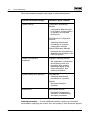
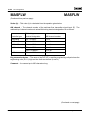
This map shows documents for interactive and computing controllers. The
number, title, and binder location are shown for each document. To help you
identify which document contains the information you are looking for, see the
descriptions on the back of this map.
Computing &
Interactive Controllers
YOU ARE HERE
ConfiguraĆ
tion EngiĆ
neering
Manual
PROVOX
Instrumentation
Installation
Planning
Manuals
Regulatory Controllers &
Data Concentrator
MainteĆ
nance
Manuals
CE4.2:CL6211
Configuring CL6010, CL6210, and
CL7010ĆSeries Interactive and Computing
Controllers
PN4.1:CD6201
Installing Type CD6201 Controller Operator
Station Units
PN4.2:CL6011
Installing CL6010, CL6210, and
CL7010ĆSeries Interactive and Computing
Controllers
PN4.4:CP6211
Installing Type CP6211 and CP6212
Controller Card File Units
PN4.10:DH6011
Installing Type DH6011 Data Concentrator
Unit and Type DH6012 Redundant Data
Concentrator Package
MM4.10:DH6003(A)
Maintaining Type DH6003, DH6011, and
DH6012 Data Concentrator Units
X00206:CL6211-0
Original Ć June 1990
CE4.2:CL6211
iv
Documentation Map
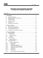
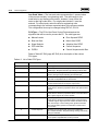
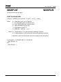
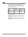
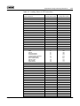
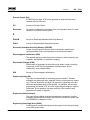
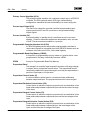
Fisher documentation supports each stage of system development.
System Development Stages
Document Type & Contents
System Design
Configuration Engineering
Manuals
Configuration dataĆentry help
for a product, including theory
of operation for improved
product use.
User Manual for Configuration
Products
Operating methods and
procedures for using the
configuration software.
Technical Reference Manuals
Advanced user information for
expanding the capability of the
PROVOX system.
System Planning and
Installation
Installation Planning Manuals
System Startup and Operation
User Manuals
Site preparation, including the
environment, power, and
grounding. Also, product
input/output signal wiring,
cable connections, and
software installation.
Operating methods and
procedures for a product.
Tutorials
Structured training of
operators.
Maintenance
Maintenance Manuals
Preventative maintenance,
calibration, troubleshooting,
and repair procedures.
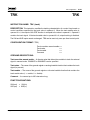
Ordering Information Ċ To order additional manuals, contact your local sales
representative, specifying the number, title, and quantity of each document required.
CE4.2:CL6211
Original Ć June 1990
Table of Contents
v
Interactive and Computing Controller
Configuration Engineering Manual
CE4.2:CL6211
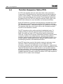
1 Introduction . . . . . . . . . . . . . . . . . . . . . . . . . . . . . . . . . . . . . . . . . . . . . . . . . . . . . . . 1Ć1
1.1
1.2
1.3
1.4
1.5
1.6
1.7
Audience Description . . . . . . . . . . . . . . . . . . . . . . . . . . . . . . . . . . . . . . . . . . . . . . . . .
Products Discussed in this Document . . . . . . . . . . . . . . . . . . . . . . . . . . . . . . . . . . .
Document Usage . . . . . . . . . . . . . . . . . . . . . . . . . . . . . . . . . . . . . . . . . . . . . . . . . . . . .
Related Documents . . . . . . . . . . . . . . . . . . . . . . . . . . . . . . . . . . . . . . . . . . . . . . . . . . .
Document Content . . . . . . . . . . . . . . . . . . . . . . . . . . . . . . . . . . . . . . . . . . . . . . . . . . . .
Conventions . . . . . . . . . . . . . . . . . . . . . . . . . . . . . . . . . . . . . . . . . . . . . . . . . . . . . . . . .
Excellence in Documentation . . . . . . . . . . . . . . . . . . . . . . . . . . . . . . . . . . . . . . . . . . .
1Ć1
1Ć1
1Ć1
1Ć2
1Ć2
1Ć2
1Ć3
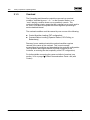
2 Product Overview . . . . . . . . . . . . . . . . . . . . . . . . . . . . . . . . . . . . . . . . . . . . . . . . . . 2Ć1
2.1
2.2
2.3
2.4
PROVOX System Overview . . . . . . . . . . . . . . . . . . . . . . . . . . . . . . . . . . . . . . . . . . . .
The Computing Controller Unit . . . . . . . . . . . . . . . . . . . . . . . . . . . . . . . . . . . . . . . . .
The Interactive Controller Unit . . . . . . . . . . . . . . . . . . . . . . . . . . . . . . . . . . . . . . . . . .
Controller/Data Concentrator Architecture . . . . . . . . . . . . . . . . . . . . . . . . . . . . . . . .
2Ć1
2Ć3
2Ć4
2Ć5
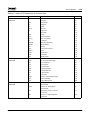
3 Theory Of Operation . . . . . . . . . . . . . . . . . . . . . . . . . . . . . . . . . . . . . . . . . . . . . . . 3Ć1
3.1
Operating States . . . . . . . . . . . . . . . . . . . . . . . . . . . . . . . . . . . . . . . . . . . . . . . . . . . . .
3.1.1
Database Hold . . . . . . . . . . . . . . . . . . . . . . . . . . . . . . . . . . . . . . . . . . . . . . . . . . . .
3.1.2
Normal Processing . . . . . . . . . . . . . . . . . . . . . . . . . . . . . . . . . . . . . . . . . . . . . . . .
3.1.3
Overload . . . . . . . . . . . . . . . . . . . . . . . . . . . . . . . . . . . . . . . . . . . . . . . . . . . . . . . . .
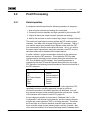
3.2
Point Processing . . . . . . . . . . . . . . . . . . . . . . . . . . . . . . . . . . . . . . . . . . . . . . . . . . . . .
3.2.1
Data Acquisition . . . . . . . . . . . . . . . . . . . . . . . . . . . . . . . . . . . . . . . . . . . . . . . . . . .
3.2.2
Fast Scan Controllers . . . . . . . . . . . . . . . . . . . . . . . . . . . . . . . . . . . . . . . . . . . . . .
3.3
Direct Control Points . . . . . . . . . . . . . . . . . . . . . . . . . . . . . . . . . . . . . . . . . . . . . . . . . .
3.3.1
Primary Control Algorithms . . . . . . . . . . . . . . . . . . . . . . . . . . . . . . . . . . . . . . . . .
3.3.1.1
Manual Loader . . . . . . . . . . . . . . . . . . . . . . . . . . . . . . . . . . . . . . . . . . . . . . . . .
3.3.1.2
Bias & Gain . . . . . . . . . . . . . . . . . . . . . . . . . . . . . . . . . . . . . . . . . . . . . . . . . . . .
3.3.1.3
High/Low Signal Selector . . . . . . . . . . . . . . . . . . . . . . . . . . . . . . . . . . . . . . .
3.3.1.4
Proportional-Derivative with Bias . . . . . . . . . . . . . . . . . . . . . . . . . . . . . . . .
3.3.1.5
Proportional-Integral-Derivative . . . . . . . . . . . . . . . . . . . . . . . . . . . . . . . .
3.3.1.6
Error Squared . . . . . . . . . . . . . . . . . . . . . . . . . . . . . . . . . . . . . . . . . . . . . . . . .
3.3.1.7
Notch Gain . . . . . . . . . . . . . . . . . . . . . . . . . . . . . . . . . . . . . . . . . . . . . . . . . . . .
3.3.1.8
Adaptive Gain . . . . . . . . . . . . . . . . . . . . . . . . . . . . . . . . . . . . . . . . . . . . . . . . . .
3.3.1.9
Control Sequence with and without Bias . . . . . . . . . . . . . . . . . . . . . . . . . .
Original Ć June 1990
3Ć1
3Ć1
3Ć1
3Ć2
3Ć3
3Ć3
3Ć4
3Ć5
3Ć5
3Ć5
3Ć6
3Ć7
3Ć8
3Ć9
3Ć11
3Ć11
3Ć12
3Ć15
CE4.2:CL6211
vi
Table of Contents
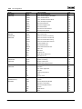
3.3.1.9.1
FST Configuration using Control Sequence PCA . . . . . . . . . . . . . . . .
3.3.1.9.2
Equations for CONTROL FST Function Block . . . . . . . . . . . . . . . . . . .
3.3.1.9.3
Equations for STATION FST Function Block . . . . . . . . . . . . . . . . . . . .
3.3.2
Station Types . . . . . . . . . . . . . . . . . . . . . . . . . . . . . . . . . . . . . . . . . . . . . . . . . . . . .
3.3.2.1
Modes . . . . . . . . . . . . . . . . . . . . . . . . . . . . . . . . . . . . . . . . . . . . . . . . . . . . . . . .
3.3.2.2
Mode Transfers . . . . . . . . . . . . . . . . . . . . . . . . . . . . . . . . . . . . . . . . . . . . . . . .
3.3.3
Direct Control Point Details . . . . . . . . . . . . . . . . . . . . . . . . . . . . . . . . . . . . . . . . .
3.3.3.1
Primary Control Algorithm Function Details . . . . . . . . . . . . . . . . . . . . . . . .
3.3.3.1.1
Anti-Reset Windup . . . . . . . . . . . . . . . . . . . . . . . . . . . . . . . . . . . . . . . . .
3.3.3.1.2
Set Point Limiting . . . . . . . . . . . . . . . . . . . . . . . . . . . . . . . . . . . . . . . . . . .
3.3.3.1.3
Set Point Velocity Limiting . . . . . . . . . . . . . . . . . . . . . . . . . . . . . . . . . . . .
3.3.3.1.4
Transfer Bias Ramping . . . . . . . . . . . . . . . . . . . . . . . . . . . . . . . . . . . . . . .
3.3.3.2
Primary Control Algorithm Modifiers . . . . . . . . . . . . . . . . . . . . . . . . . . . . . .
3.3.3.2.1
Dead-time Compensation . . . . . . . . . . . . . . . . . . . . . . . . . . . . . . . . . . .
3.3.3.2.2
Override . . . . . . . . . . . . . . . . . . . . . . . . . . . . . . . . . . . . . . . . . . . . . . . . . . .
3.3.3.2.3
Track . . . . . . . . . . . . . . . . . . . . . . . . . . . . . . . . . . . . . . . . . . . . . . . . . . . . . .
3.3.3.2.4
Gas Chromatograph Interface . . . . . . . . . . . . . . . . . . . . . . . . . . . . . . . .
3.3.3.2.5
Cascade . . . . . . . . . . . . . . . . . . . . . . . . . . . . . . . . . . . . . . . . . . . . . . . . . . .
3.3.3.3
Station Function Details . . . . . . . . . . . . . . . . . . . . . . . . . . . . . . . . . . . . . . . . .
3.3.3.3.1
Alarm Processing . . . . . . . . . . . . . . . . . . . . . . . . . . . . . . . . . . . . . . . . . . .
3.3.3.3.2
Output Limiting . . . . . . . . . . . . . . . . . . . . . . . . . . . . . . . . . . . . . . . . . . . . .
3.3.3.3.3
Watchdog Timer . . . . . . . . . . . . . . . . . . . . . . . . . . . . . . . . . . . . . . . . . . . .
3.3.3.4
Functions Common to Primary Control Algorithm and Station . . . . . . . .
3.3.3.4.1
Restart Values . . . . . . . . . . . . . . . . . . . . . . . . . . . . . . . . . . . . . . . . . . . . . .
3.3.3.4.2
Set Point Tracking . . . . . . . . . . . . . . . . . . . . . . . . . . . . . . . . . . . . . . . . . . .
3.3.4
Direct Control Point Diagrams . . . . . . . . . . . . . . . . . . . . . . . . . . . . . . . . . . . . . . .
3.4
Upload/Download . . . . . . . . . . . . . . . . . . . . . . . . . . . . . . . . . . . . . . . . . . . . . . . . . . . .
3.4.1
Initiating a Download . . . . . . . . . . . . . . . . . . . . . . . . . . . . . . . . . . . . . . . . . . . . . . .
3.4.2
Completing a Download . . . . . . . . . . . . . . . . . . . . . . . . . . . . . . . . . . . . . . . . . . . .
3.4.3
Tuning Parameter Upload . . . . . . . . . . . . . . . . . . . . . . . . . . . . . . . . . . . . . . . . . . .
3.4.4
Redundant Controller Downloads . . . . . . . . . . . . . . . . . . . . . . . . . . . . . . . . . . . .
3.5
Communications . . . . . . . . . . . . . . . . . . . . . . . . . . . . . . . . . . . . . . . . . . . . . . . . . . . . .
3.5.1
Process Data Communications . . . . . . . . . . . . . . . . . . . . . . . . . . . . . . . . . . . . . .
3.5.2
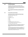
Maintenance Data Communications . . . . . . . . . . . . . . . . . . . . . . . . . . . . . . . . .
3.5.3
Task Priorities . . . . . . . . . . . . . . . . . . . . . . . . . . . . . . . . . . . . . . . . . . . . . . . . . . . .
3.5.4
Trade-offs between Communications and Control . . . . . . . . . . . . . . . . . . . .
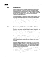
3.6
Redundancy . . . . . . . . . . . . . . . . . . . . . . . . . . . . . . . . . . . . . . . . . . . . . . . . . . . . . . . . .
3.6.1
Redundancy Architecture and Definition of Terms . . . . . . . . . . . . . . . . . . . . . .
3.6.2
Redundant Controller Upload and Download . . . . . . . . . . . . . . . . . . . . . . . . . .
3.6.2.1
Upload and Download Transparency . . . . . . . . . . . . . . . . . . . . . . . . . . . . .
3.6.2.2
Initialization of Control Action After Download . . . . . . . . . . . . . . . . . . . . . .
3.6.2.3
Recovery After Configuration Download Error Detection . . . . . . . . . . . . .
3.6.3
Redundant Controller Normal Online Operation . . . . . . . . . . . . . . . . . . . . . . .
3.6.3.1
Inter-Controller Tracking . . . . . . . . . . . . . . . . . . . . . . . . . . . . . . . . . . . . . . . .
CE4.2:CL6211
3Ć16
3Ć16
3Ć17
3Ć17
3Ć18
3Ć18
3Ć19
3Ć19
3Ć20
3Ć21
3Ć21
3Ć21
3Ć22
3Ć22
3Ć23
3Ć24
3Ć24
3Ć24
3Ć25
3Ć25
3Ć27
3Ć28
3Ć28
3Ć28
3Ć29
3Ć29
3Ć48
3Ć48
3Ć48
3Ć49
3Ć49
3Ć50
3Ć50
3Ć51
3Ć51
3Ć52
3Ć53
3Ć53
3Ć54
3Ć54
3Ć54
3Ć54
3Ć55
3Ć55
Original Ć June 1990
Table of Contents
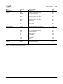
3.6.3.2
Tuning Parameter Handshake . . . . . . . . . . . . . . . . . . . . . . . . . . . . . . . . . . . .
3.6.4
Redundant Controller Power Fail Restart . . . . . . . . . . . . . . . . . . . . . . . . . . . . .
3.6.4.1
Active and Standby Controller Determination . . . . . . . . . . . . . . . . . . . . . .
3.6.4.2
Operating Parameter Restart Values . . . . . . . . . . . . . . . . . . . . . . . . . . . . . .
3.6.4.3
Configuration Validation . . . . . . . . . . . . . . . . . . . . . . . . . . . . . . . . . . . . . . . . .
3.6.5
Failure Detection . . . . . . . . . . . . . . . . . . . . . . . . . . . . . . . . . . . . . . . . . . . . . . . . . .
3.6.6
Control Action After Switchover/Switchback . . . . . . . . . . . . . . . . . . . . . . . . . . .
3.7
Controller Self Test . . . . . . . . . . . . . . . . . . . . . . . . . . . . . . . . . . . . . . . . . . . . . . . . . . . .
3.7.1
Ram/Rom Check . . . . . . . . . . . . . . . . . . . . . . . . . . . . . . . . . . . . . . . . . . . . . . . . . .
3.7.2
Non-Volatile Memory Check . . . . . . . . . . . . . . . . . . . . . . . . . . . . . . . . . . . . . . .
3.7.3
Analog Output Self Test . . . . . . . . . . . . . . . . . . . . . . . . . . . . . . . . . . . . . . . . . . . .
3.7.4
Discrete Input Output Self Test . . . . . . . . . . . . . . . . . . . . . . . . . . . . . . . . . . . . . .
3.7.5
Communications Error Rate Excessive Self Test . . . . . . . . . . . . . . . . . . . . . . .
3.7.6
Function Sequence Table (FST) Overload Self Test . . . . . . . . . . . . . . . . . . . .
3.7.7
Free Time Computation . . . . . . . . . . . . . . . . . . . . . . . . . . . . . . . . . . . . . . . . . . . .
3.7.8
Recommended Minimum Free Time Value . . . . . . . . . . . . . . . . . . . . . . . . . . . .
vii
3Ć55
3Ć55
3Ć56
3Ć56
3Ć56
3Ć56
3Ć58
3Ć59
3Ć59
3Ć59
3Ć59
3Ć60
3Ć60
3Ć60
3Ć60
3Ć61
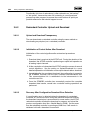
4 Configuration . . . . . . . . . . . . . . . . . . . . . . . . . . . . . . . . . . . . . . . . . . . . . . . . . . . . . 4Ć1
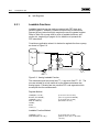
4.1
Configuring IAC and Computing Controllers . . . . . . . . . . . . . . . . . . . . . . . . . . . . . .
4.1.1
Configuration Tasks . . . . . . . . . . . . . . . . . . . . . . . . . . . . . . . . . . . . . . . . . . . . . . . .
4.1.1.1
Creating Configuration Data . . . . . . . . . . . . . . . . . . . . . . . . . . . . . . . . . . . . .
4.1.1.2
Generating Configuration Data . . . . . . . . . . . . . . . . . . . . . . . . . . . . . . . . . . .
4.1.1.3
Downloading Configuration Data . . . . . . . . . . . . . . . . . . . . . . . . . . . . . . . . .
4.1.2
ConfigurationĆRelated Activities . . . . . . . . . . . . . . . . . . . . . . . . . . . . . . . . . . . . .
4.1.2.1
Upload . . . . . . . . . . . . . . . . . . . . . . . . . . . . . . . . . . . . . . . . . . . . . . . . . . . . . . . .
4.1.2.2
Documentation . . . . . . . . . . . . . . . . . . . . . . . . . . . . . . . . . . . . . . . . . . . . . . . .
4.1.3
Organization of Configuration Information . . . . . . . . . . . . . . . . . . . . . . . . . . . .
4.2
Device Definition . . . . . . . . . . . . . . . . . . . . . . . . . . . . . . . . . . . . . . . . . . . . . . . . . . . . . .
4.2.1
FST Registers . . . . . . . . . . . . . . . . . . . . . . . . . . . . . . . . . . . . . . . . . . . . . . . . . . . . .
4.2.2
Aux EU Definition . . . . . . . . . . . . . . . . . . . . . . . . . . . . . . . . . . . . . . . . . . . . . . . . . .
4.2.3
Operator Stations Definition . . . . . . . . . . . . . . . . . . . . . . . . . . . . . . . . . . . . . . . . .
4.3
Direct Control Point Configuration . . . . . . . . . . . . . . . . . . . . . . . . . . . . . . . . . . . . . .
4.3.1
Direct Control Point Definition . . . . . . . . . . . . . . . . . . . . . . . . . . . . . . . . . . . . . . .
4.3.2
Primary Control Algorithm (PCA) . . . . . . . . . . . . . . . . . . . . . . . . . . . . . . . . . . . .
4.3.3
Adaptive/Notch Gain Parameters . . . . . . . . . . . . . . . . . . . . . . . . . . . . . . . . . . . .
4.3.4
Station Parameters . . . . . . . . . . . . . . . . . . . . . . . . . . . . . . . . . . . . . . . . . . . . . . . .
4.3.5
DCP Cross Reference Definition . . . . . . . . . . . . . . . . . . . . . . . . . . . . . . . . . . . . .
4.3.6
DCP Register DDP Definition . . . . . . . . . . . . . . . . . . . . . . . . . . . . . . . . . . . . . . . .
4.4
Function Sequence Table (FST) . . . . . . . . . . . . . . . . . . . . . . . . . . . . . . . . . . . . . . . .
4.5
IAC/Computing Analog ICP Point . . . . . . . . . . . . . . . . . . . . . . . . . . . . . . . . . . . . . . .
4.6
IAC/Computing Discrete ICP Point . . . . . . . . . . . . . . . . . . . . . . . . . . . . . . . . . . . . . .
4.7
Target Data Configuration . . . . . . . . . . . . . . . . . . . . . . . . . . . . . . . . . . . . . . . . . . . . . .
4.7.1
Target Data Configuration Items . . . . . . . . . . . . . . . . . . . . . . . . . . . . . . . . . . . . .
Original Ć June 1990
4Ć1
4Ć1
4Ć1
4Ć4
4Ć4
4Ć4
4Ć4
4Ć4
4Ć5
4Ć6
4Ć7
4Ć8
4Ć8
4Ć11
4Ć11
4Ć13
4Ć17
4Ć20
4Ć22
4Ć23
4Ć24
4Ć166
4Ć168
4Ć170
4Ć170
CE4.2:CL6211
viii
Table of Contents
4.7.1.1
4.7.1.2
4.7.1.3
UOC Target Data Configuration Items . . . . . . . . . . . . . . . . . . . . . . . . . . . . . 4Ć172
PROVUE Target Data Configuration Items . . . . . . . . . . . . . . . . . . . . . . . . . 4Ć176
Trend Target Data Configuration Items . . . . . . . . . . . . . . . . . . . . . . . . . . . . 4Ć179
5 Configuration Tips . . . . . . . . . . . . . . . . . . . . . . . . . . . . . . . . . . . . . . . . . . . . . . . . . 5Ć1
5.1
5.2
5.3
5.3.1
5.3.2
5.3.3
5.4
5.5
5.6
5.7
5.7.1
5.7.2
5.7.3
5.7.4
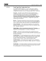
Targeting Points . . . . . . . . . . . . . . . . . . . . . . . . . . . . . . . . . . . . . . . . . . . . . . . . . . . . . .
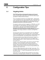
Ratio Control . . . . . . . . . . . . . . . . . . . . . . . . . . . . . . . . . . . . . . . . . . . . . . . . . . . . . . . . .
Register Conservation Techniques . . . . . . . . . . . . . . . . . . . . . . . . . . . . . . . . . . . . . .
Loadable Functions . . . . . . . . . . . . . . . . . . . . . . . . . . . . . . . . . . . . . . . . . . . . . . . .
Scratch Registers . . . . . . . . . . . . . . . . . . . . . . . . . . . . . . . . . . . . . . . . . . . . . . . . . .
Split Registers . . . . . . . . . . . . . . . . . . . . . . . . . . . . . . . . . . . . . . . . . . . . . . . . . . . .
Tunable Discrete I/O Logic . . . . . . . . . . . . . . . . . . . . . . . . . . . . . . . . . . . . . . . . . . . . .
Zero Dropout on Analog Inputs . . . . . . . . . . . . . . . . . . . . . . . . . . . . . . . . . . . . . . . . .
Loop Mode FST Functions . . . . . . . . . . . . . . . . . . . . . . . . . . . . . . . . . . . . . . . . . . . . .
Use Of Filtering In Override
Control Applications . . . . . . . . . . . . . . . . . . . . . . . . . . . . . . . . . . . . . . . . . . . . . . . . . .
Use Of Filtering In Override Control On Loops With
Similar Dynamic Characteristics . . . . . . . . . . . . . . . . . . . . . . . . . . . . . . . . . . . . .
Use Of Filtering In Override Control On Loops With
Significantly Different Dynamic Characteristics . . . . . . . . . . . . . . . . . . . . . . . .
Use Of Filtering For Override Control On Slow Loops . . . . . . . . . . . . . . . . . .
Operating Characteristics Of Override Control Loops . . . . . . . . . . . . . . . . . .
5Ć1
5Ć2
5Ć3
5Ć4
5Ć6
5Ć6
5Ć7
5Ć8
5Ć8
5Ć9
5Ć9
5Ć10
5Ć10
5Ć12
Appendix A Loading and Sizing Calculations . . . . . . . . . . . . . . . . . . . . . . . . . . . AĆ1
A.1
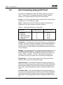
Loading Calculations . . . . . . . . . . . . . . . . . . . . . . . . . . . . . . . . . . . . . . . . . . . . . . . . . .
A.1.1
Simplex Controller Loading . . . . . . . . . . . . . . . . . . . . . . . . . . . . . . . . . . . . . . . . .
A.1.2
Redundant Controller Loading . . . . . . . . . . . . . . . . . . . . . . . . . . . . . . . . . . . . . .
A.2
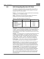
Sizing Calculations . . . . . . . . . . . . . . . . . . . . . . . . . . . . . . . . . . . . . . . . . . . . . . . . . . . .
A.2.1
Simplex Controller Sizing . . . . . . . . . . . . . . . . . . . . . . . . . . . . . . . . . . . . . . . . . . .
A.2.2
Redundant Controller Sizing . . . . . . . . . . . . . . . . . . . . . . . . . . . . . . . . . . . . . . . .
AĆ1
AĆ2
AĆ3
AĆ4
AĆ4
AĆ5
Glossary
Index
CE4.2:CL6211
Original Ć June 1990
Table of Contents
ix
Figures
2Ć1
2Ć2
3Ć1
3Ć2
3Ć3
3Ć4
3Ć5
3Ć6
3Ć7
3Ć8
3Ć9
3Ć10
3Ć11
4Ć1
4Ć2
4Ć3
5Ć1
5Ć2
Typical Data Highway Installation with a Secondary Highway . . . . . . . . . . . . . . . . . 2Ć1
Controller/Data Concentrator Architecture . . . . . . . . . . . . . . . . . . . . . . . . . . . . . . . . . . 2Ć5
Effects of Bias & Gain . . . . . . . . . . . . . . . . . . . . . . . . . . . . . . . . . . . . . . . . . . . . . . . . . . . 3Ć7
One Half Proportional Band Concept . . . . . . . . . . . . . . . . . . . . . . . . . . . . . . . . . . . . . 3Ć10
Error Squared Algorithm Response . . . . . . . . . . . . . . . . . . . . . . . . . . . . . . . . . . . . . . 3Ć11
Notch Gain Algorithm Response . . . . . . . . . . . . . . . . . . . . . . . . . . . . . . . . . . . . . . . . . 3Ć12
Process Variable Adaptive Gain . . . . . . . . . . . . . . . . . . . . . . . . . . . . . . . . . . . . . . . . . . 3Ć14
Implied Valve Position Adaptive Gain . . . . . . . . . . . . . . . . . . . . . . . . . . . . . . . . . . . . . 3Ć15
Discrete Adaptive Gain . . . . . . . . . . . . . . . . . . . . . . . . . . . . . . . . . . . . . . . . . . . . . . . . . 3Ć15
Anti-Reset Windup . . . . . . . . . . . . . . . . . . . . . . . . . . . . . . . . . . . . . . . . . . . . . . . . . . . . 3Ć20
Transfer Bias Ramping . . . . . . . . . . . . . . . . . . . . . . . . . . . . . . . . . . . . . . . . . . . . . . . . . 3Ć22
Absolute Alarms . . . . . . . . . . . . . . . . . . . . . . . . . . . . . . . . . . . . . . . . . . . . . . . . . . . . . . . 3Ć26
Deviation Alarms . . . . . . . . . . . . . . . . . . . . . . . . . . . . . . . . . . . . . . . . . . . . . . . . . . . . . . 3Ć27
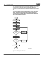
Configuration Flowchart . . . . . . . . . . . . . . . . . . . . . . . . . . . . . . . . . . . . . . . . . . . . . . . . . 4Ć2
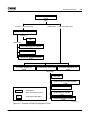
Overview of ENVOX Configuration Forms . . . . . . . . . . . . . . . . . . . . . . . . . . . . . . . . . . 4Ć3
Operator Station Port Numbering of IAC Cards . . . . . . . . . . . . . . . . . . . . . . . . . . . . . 4Ć9
Ratio Control . . . . . . . . . . . . . . . . . . . . . . . . . . . . . . . . . . . . . . . . . . . . . . . . . . . . . . . . . . . 5Ć2
Analog Loadable Function . . . . . . . . . . . . . . . . . . . . . . . . . . . . . . . . . . . . . . . . . . . . . . . 5Ć4
Tables
4Ć1
4Ć2
4Ć3
4Ć4
4Ć5
4Ć6
4Ć7
4Ć8
4Ć9
4Ć10
4Ć11
AĆ1
AĆ2
Access to Register Types . . . . . . . . . . . . . . . . . . . . . . . . . . . . . . . . . . . . . . . . . . . . . . . . 4Ć7
Valid Operator Station Port Numbers . . . . . . . . . . . . . . . . . . . . . . . . . . . . . . . . . . . . . . 4Ć9
List of Valid PCA Types . . . . . . . . . . . . . . . . . . . . . . . . . . . . . . . . . . . . . . . . . . . . . . . . . 4Ć12
List of Valid PCA / Station Combinations . . . . . . . . . . . . . . . . . . . . . . . . . . . . . . . . . . 4Ć14
Index of FST Instructions by Function Type . . . . . . . . . . . . . . . . . . . . . . . . . . . . . . . 4Ć25
Loadable Functions . . . . . . . . . . . . . . . . . . . . . . . . . . . . . . . . . . . . . . . . . . . . . . . . . . . . 4Ć28
Valid Index Numbers for Analog ICPs. . . . . . . . . . . . . . . . . . . . . . . . . . . . . . . . . . . . 4Ć166
Access to Analog ICP Types . . . . . . . . . . . . . . . . . . . . . . . . . . . . . . . . . . . . . . . . . . . 4Ć167
Valid Index Numbers for Discrete ICPs. . . . . . . . . . . . . . . . . . . . . . . . . . . . . . . . . . . 4Ć168
Access to Discrete ICP Types . . . . . . . . . . . . . . . . . . . . . . . . . . . . . . . . . . . . . . . . . . 4Ć169
Extended Alarm Attributes for UOC AI and Loop Points . . . . . . . . . . . . . . . . . . . . 4Ć174
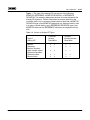
Maximum Controller Loading Values . . . . . . . . . . . . . . . . . . . . . . . . . . . . . . . . . . . . . . AĆ2
Loading Values for FST Instructions . . . . . . . . . . . . . . . . . . . . . . . . . . . . . . . . . . . . . . . AĆ7
Original Ć June 1990
CE4.2:CL6211
x
Table of Contents
This page intentionally left blank.
CE4.2:CL6211
Original Ć June 1990
Introduction
1
Introduction
1.1
Audience Description
1Ć1
This Configuration Engineering Manual contains the information needed
to configure the Interactive and Computing Controllers, and is written for
the configuration engineer who is familiar with these controllers and the
ENVOX t configuration system.
The Fisher Educational Services course in System Configuration
provides training to the skill level required to effectively use this manual.
Using ENVOX Configuration Software (UM4.14:SW3151) and this
Configuration Engineering Manual supplement the information presented
in this course, and may be used as reference documents during
configuration.
1.2
Products Discussed in this Document
This document will deals with Type CL6011 / CL6012 Interactive
Controllers and Type CL6211 / CL7011 / CL7012 Computing Controllers.
These products are compatible with the ENVOX configuration system.
This document does not provide information relating to other PROVOXr
devices, except where those devices directly affect, or are affected by,
the Interactive and Computing Controllers.
1.3
Document Usage
If you are not familiar with the Interactive and Computing Controllers,
read sections 1, 2, and 3. These sections describe how the PROVOX
system works, and provide the operating theory for the Interactive and
Computing Controllers.
If you understand the theory of operation for the Interactive and
Computing Controllers, begin with sections 4 and 5; they provide
practical configuration information.
PROVOX is a registered trademark of Fisher Controls International, Inc.
ENVOX is a trademark of Fisher Controls International, Inc.
Original Ć June 1990
CE4.2:CL6211
1Ć2
Introduction
1.4
Related Documents
The Documentation Map at the front of this manual shows the
documentation for the Interactive and Computing Controllers.
Additional reference documents are:
1.5
J
Using ENVOX Configuration Software (UM4.14:SW3151)
J
Type CD6201 Controller Operator Station Unit (Bulletin 4.1:CD6201)
J
Type CL6011 and CL6012 Interactive Controllers (Bulletin 4.2:CL6011
and Bulletin 4.2:CL6011[S1] )
J
Type CL6211, CL7011 and CL7012 Computing Controllers
(Bulletin 4.2:CL6211 and Bulletin 4.2:CL6211[S1] )
J
Type CP6211 amd CP6212 Controller Card File Units
(Bulletin 4.4:CP6211)
J
Type DH6011 Data Concentrator and DH6012 Redundant Data
Concentrator (Bulletin 4.10:DH6011)
Document Content
The full contents of this document are described below, with additional
detail shown in the table of contents.
Section 1 introduces this manual and includes the purpose of this
document, the intended audience, and conventions.
Section 2 provides an overview of PROVOX DCS products, the
Interactive and Computing Controllers, and an explanation of how each
product is used in a PROVOX system.
Section 3 provides a description of the theory of operation of the
Interactive and Computing Controllers.
Section 4 presents the information needed for configuring the Interactive
and Computing Controllers.
Section 5 provides Interactive and Computing Controller configuration
tips.
Appendix A contains loading and sizing information.
A glossary of process control terminology, an index of the information in
this document, and a Reader Evaluation Form are also included.
1.6
Conventions
The following conventions are used in this document:
CE4.2:CL6211
Original Ć June 1990
Introduction
1Ć3
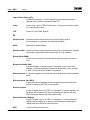
Abbreviations — The configuration system on-line HELP messages
include the definition of abbreviations which are used in this document.
The same information is also included in the glossary of this document.
Revision Control — The title page of each document lists the printing
date of the document. The product version number covered in the
document is listed in section 1.2
Cross Referencing — References to other documents for additional
information list the document name. See the Documentation Map for the
document number.
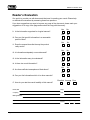
1.7
Excellence in Documentation
Our goal is to provide you with documents that excel in meeting your
needs. Through surveys and interviews, we continually evaluate our
documents as part of the broad Fisher customer-support program.
Various documents are produced for different purposes and for readers
with varying backgrounds and experience. This manual was written for
the reader level described in section 1.1.
To help us evaluate how well this manual fills your needs, please
complete the survey form included inside the back cover. If you have
suggestions on ways to improve any page of the document, please mark
your suggestions on a copy of the page and enclose the copy with the
survey. Thank you for providing this information.
Original Ć June 1990
CE4.2:CL6211
1Ć4
Introduction
This page intentionally left blank.
CE4.2:CL6211
Original Ć June 1990
Product Overview
2
Product Overview
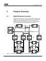
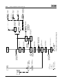
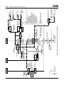
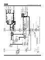
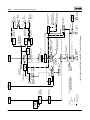
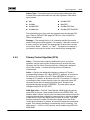
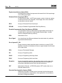
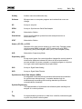
2.1
PROVOX System Overview
2Ć1
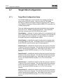
A PROVOX system consists of a set of individual devices that are linked
together by a communications scheme referred to as the PROVOX Data
Highway. All communicating PROVOX devices are connected to this
highway. Figure NO TAG illustrates the layout of a system and how the
primary and secondary communication paths are connected.
C
I
A
PRIMARY
NETWORK
TRAFFIC
DIRECTOR
C
I
A
SECONDARY
NETWORK
TRAFFIC
DIRECTOR
C
I
A
C
I
A
NETWORK
DEVICE
1
C
I
A
UP TO SIX
NETWORK
DEVICES
C
I
A
NETWORK
DEVICE
6
PRIMARY NETWORK DATA HIGHWAY
SECONDARY NETWORK DATA HIGHWAY
UP TO EIGHT
LOCAL AREAS
LOCAL
AREA
1
CIA
C
I
A
LOCAL
DEVICE
1
C
I
A
C
I
A
LOCAL
DEVICE
2
C
I
A
UP TO 30 LOCAL
DEVICES
C
I
A
LOCAL
DEVICE
30
C
I
A
SECONDARY LOCAL DATA HIGHWAY
PRIMARY LOCAL DATA HIGHWAY
CIA
CIA
CIA
PRIMARY
LOCAL
TRAFFIC
DIRECTOR
SECONDARY
LOCAL
TRAFFIC
DIRECTOR
LOCAL
AREA
8
CIA
CIA
C
I
A
LOCAL
DEVICE
1
C
I
A
C
I
A
LOCAL
DEVICE
2
C
I
A
UP TO 30 LOCAL
DEVICES
C
I
A
LOCAL
DEVICE
30
SECONDARY LOCAL DATA HIGHWAY
CIA
SECONDARY
LOCAL
TRAFFIC
DIRECTOR
PRIMARY LOCAL DATA HIGHWAY
CIA
PRIMARY
LOCAL
TRAFFIC
DIRECTOR
C
I
A
Figure 2Ć1. Typical Data Highway Installation with a Secondary Highway
Original Ć June 1990
CE4.2:CL6211
2Ć2
Product Overview
The following paragraphs provide a brief description of each PROVOX
device that can be connected to the PROVOX Data Highway. These
devices can be connected as either network or local devices.
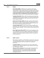
PROVUEr Ċ The PROVUE operations consoles are a family of operator
interface devices, each of which consists of an electronics unit and up to
four high resolution color video display units. PROVUE consoles are
used to operate processes being controlled by PROVOX devices.
ENVOX Ċ An ENVOX workstation consists of an interface card file and a
desk top computer with a Fisher configuration software package. It is
used for configuring PROVOX devices, and for performing device
diagnostics.
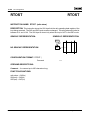
20ĆSeries (SR90) Controller Family Ċ The 20ĆSeries (SR90) Controller
Family is made up of three devices: the Multiplexer, the Integrated
Function Controller, and the Unit Operations Controller. These
controllers are referred to as a family" because they share a common
hardware and software platform, and are designed for batch and
continuous control applications.
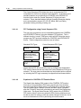
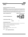
Programmable Controller Interface Unit Ċ The Programmable
Controller Interface Unit (PCIU) permits the monitoring of programmable
controller (PLC) operation. Communication between the PLC and PCIU
is conducted over an RS232C link.
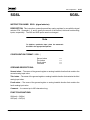
Multiplexer Ċ The Multiplexer is a data acquisition device that accepts
input signals from a wide variety of analog, discrete, and pulse count
sources.
Trend Unit Ċ The Trend Unit allows the user to store or display selected
process data from PROVOX devices. Trend data may be stored in RAM
on a temporary basis or to floppy if a permanent record is desired. A
display of the trended data may be viewed on a console and a hard copy
may be made if necessary.
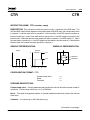
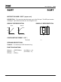
Local Traffic Director Ċ The Local Traffic Director (LTD) is a highway
device that controls communications between the devices on a local
data highway. The LTD is also used to manage communications
between a device on the local highway and a device on the network
highway. Two LTDs may be used in a local area for redundant
communication capability.
Network Traffic Director Ċ The Network Traffic Director (NTD) is a
PROVOX Data Highway device that controls the communications of
network devices and communicates with the local areas through LTDs.
Two NTDs may be used to provide redundant communication capability.
PROVUE is a registered trademark of Fisher Controls International, Inc.
CE4.2:CL6211
Original Ć June 1990
Product Overview
2Ć3
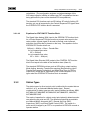
Computer / Highway Interface Package Ċ The Computer/Highway
Interface Package (CHIP) provides plant computers with access to the
entire PROVOX process database. This allows users to do special
calculations for optimization, reporting, process analysis, and other plant
management tasks.
Application Software Ċ Application software consists of packages such
as Data Historian, Console Trend Display, and Batch Data Manager.
These software packages perform a variety of data
acquisition/management/display functions. Application software
packages interface with PROVOX devices through the CHIP.
Data Concentrator Unit / Regulatory Controller Ċ The Data
Concentrator Unit (DCU) is a device which serves as a buffer between
the PROVOX Data Highway and Configurable, Computing, and
Interactive Controllers. These controllers are designed for continuous
control applications.
2.2
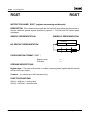
The Computing Controller Unit
The Computing Controller is a user-configured, digital controller for
continuous processes. It combines advanced computing power with
linear and nonlinear control for single loop and cascade control
applications. The controller can perform control tasks such as blending,
temperature and flow linearization, pH control, and mass flow
calculations. Operator interface is achieved through a system console or
through a panel-mounted operator station.
The Type CL7011 Computing Controller Assembly consists of a printed
circuit card that occupies one slot in a rack-mounted controller card file.
The computing controller assembly employs a microprocessor for
performing signal processing and communications. All calculations use
floating-point arithmetic to reduce scaling requirements. Predefined
control algorithms and functions are contained in the controller for
simplified configuration. Because all configuration data are retained in
nonvolatile memory, re-configuration of the controller after a power
failure is normally not required. All process input and output (I/O), Data
Concentrator, and power connections between the controller and the
card file are made through the back edge of the controller card. Operator
station communications and power are provided through a connector on
the front edge of the controller card. The Type CL6211 Computing
Controller Assembly consists of a Type CL7011 Computing Controller
Assembly and a Type CD6201 Controller Operator Station Unit. The
Type CL7012 Computing Controller Assembly is a redundant version of
the Type CL7011 Computing Controller Assembly.
Original Ć June 1990
CE4.2:CL6211
2Ć4
Product Overview
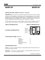
2.3
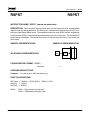
The Interactive Controller Unit
The Interactive Controller Unit (IAC) is a user-configured, digital
controller for continuous processes. It has the control and computing
capability to implement complex applications requiring interaction among
several loops. The controller can perform complex strategies such as
distillation column control, industrial boiler control, and combustion
control. Operator interface is achieved through a system console or
through panel-mounted operator stations.
The Type CL6011 Interactive Controller Unit consists of various printed
circuit card assemblies and interconnect assemblies that are combined
to form four models as follows:
H
H
H
H
2-wide unit
3-wide (with discrete I/O) unit
3-wide (with process I/O) unit
4-wide unit
Each of the four models contains a microprocessor unit (MPU) card
assembly. The MPU card performs the central processing for the
controller and handles all communications between the controller and
devices on the data highway, such as a console. All calculations use
floating- point arithmetic to reduce scaling requirements. The MPU card
also produces and receives discrete signals to and from field devices.
In addition to the MPU card, each model also contains one or two Type
CL7015 Process I/O Assemblies. The process I/O card accepts analog
input signals from field devices, performs analog-to-digital and
digital-to-analog conversions, and generates analog output signals to
field devices. Since the process I/O card has its own microprocessor, it
maintains all analog outputs independent of the MPU card for added
security. Each process I/O card has two ports through which the
controller can communicate with two operator stations.
Two of the interactive controller models contain a Type CL7014 Discrete
I/O Assembly. The discrete I/O card receives discrete signals from field
devices and produces discrete signals to field devices. In addition, the
discrete I/O card has two operator station ports.
The 2-wide and 4-wide interconnect assemblies provide all the
necessary electrical connections between the card assemblies. The Type
CL7016 Interconnect Assembly (2-wide) provides connections between
the two cards of the 2-wide model, occupying two slots in a controller
card file. The Type CL7006 Interconnect Assembly (4-wide) provides
connections between the three or four cards of the 3 or 4-wide models,
occupying four slots in a controller card file. Both interconnect
assemblies attach to the backplane of the controller card file; in this way,
interconnects are made simultaneously with card file connections when
the controller cards are installed in the card file.
CE4.2:CL6211
Original Ć June 1990
Product Overview
2Ć5
The Type CL6012 Interactive Controller Assembly is a redundant version
of the Type CL6011 Interactive Controller Assembly.
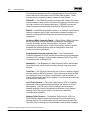
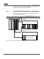
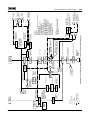
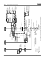
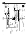
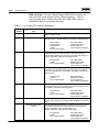
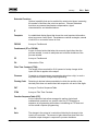
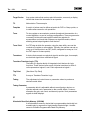
2.4
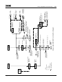
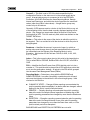
Controller/Data Concentrator Architecture
The Interactive and Computing Controllers are connected to the Data
Concentrator as shown in Figure 2Ć2.
SECONDARY DATA HIGHWAY
PRIMARY DATA HIGHWAY
2-WIDE IAC
PIO
MPU
PIO
DIO
MPU
PIO
PCC
FILE # 1
PCC
PRIMARY CIA
SECONDARY CIA
I/O
MPU
DATA CONCENTRATOR UNIT
4-WIDE IAC
UP TO 8 CARDS
COMPUTING
PCC
PCC
FILE # 2
Figure 2Ć2. Controller/Data Concentrator Architecture
Original Ć June 1990
CE4.2:CL6211
2Ć6
Product Overview
This page intentionally left blank.
CE4.2:CL6211
Original Ć June 1990
Theory of Operation: Operating States
3
Theory Of Operation
3.1
Operating States
3.1.1
Database Hold
3Ć1
A Regulatory Controller may power up in a state termed Database Hold"
or No Configuration", which simply means that the controller has not
been loaded with a user configuration. A user configuration is required
to allow the device to perform the desired algorithm(s). A Regulatory
Controller in Database Hold is indicated by error -7-" on an Operator
Station, or the Unavailable" integrity error on an operator's console. To
correct this condition, the user must download the desired configuration
to the controller (see section NO TAG on page NO TAG for details
concerning Upload/Download).
A controller may enter the Database Hold state under the following
conditions:
H When first powered up after being received from the factory;
Recovery - See the Installation/Maintenance manual
H After being un-powered for a time period exceeding 24 hours;
Recovery - See the Installation/Maintenance Manual
H After rejecting an attempted user download that exceeds the capacity of
the device (either a configuration error was detected during download, or
the device limits, such as available RAM, have been exceeded).
Recovery - The user should correct the configuration error, or reduce
the size of the configuration, and re-attempt the download.
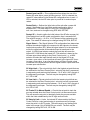
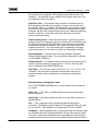
3.1.2
Normal Processing
After the controller has received a successful download of the user's
configuration, the controller enters the Normal Processing state. In this
state, all of the normal controller functions are performed, such as point
processing (input and output scanning, and control algorithm
processing), communications processing, and self test operations.
Original Ć June 1990
CE4.2:CL6211
3Ć2
Theory of Operation: Operating States
3.1.3
Overload
The Computing and Interactive controllers can reach an overload
condition, indicated by error -0-" on the Operator Station, or an
error" integrity condition shown on an operator's console. This
overload condition simply means that the controller has so much work to
do, that it is not able to complete the control algorithm processing in
each scheduled interval.
The overload condition could be caused by one or more of the following:
H Control Algorithm Loading (FST configuration)
H Communications Loading (Operator Stations, DCU Polling, or
Redundancy)
Recovery from a sustained controller overload condition requires
removal of the cause of the overload. This is most normally
accomplished by modifying and downloading the controller configuration
(such as either reducing the number of points configured in the
controller, or reducing the size/complexity of the FST configuration).
For further details concerning the cause and effect of overload, see
section 3.5.4 on page 3 52 titled Communications Trade-offs (with
Control).
CE4.2:CL6211
Original Ć June 1990
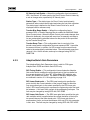
Theory of Operation: Point Processing
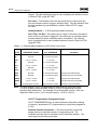
3.2
Point Processing
3.2.1
Data Acquisition
3Ć3
A configured controller performs the following operations in sequence:
1. Scan all inputs (discrete and analog) for current data.
2. Process the control algorithm and logic specified by the controller FST.
3. Output all data to the output channels (discrete and analog).
4. Wait for the next time to run the control logic (steps 1 through 3 above).
This method of input/output scanning isolates the FST, and the output
channels, from data value changes during the FST execution. That is, if
you read the same input channel at two different points within the FST,
you are assured to read the same value both times. Also, if you write to
the same output channel twice during the execution of an FST, only the
last value written will be detected at the output channel.
A similar isolation" of the communication channels is also performed
before and after the FST execution. This isolates the FST from data
change requests received from an operator during the execution of an
FST, such as Mode and SP changes. If an operating parameter is
changed by both the FST and the Operator during the time of a single
FST execution, the following forced precedence is enforced at the end of
the FST execution:
Operating Parameter
Precedence
PV
SP
IVP (Valve Output)
Mode
Bias
Ratio
Control
Communications
Communications
Control
Control
Control
A side effect of this forced precedence is, if the control algorithm (FST)
repeatedly forces an operating parameter change to a point on
successive executions, the control algorithm can effectively lock out"
any operator changes to that operating parameter on that point. Details
of this situation are included in section 5.6 (page 5Ć9).
An unconfigured controller (current state is Database Hold" or No
Configuration") will still scan input channels, and force output channels;
however the control algorithm (FST) is not being executed. This allows
the Trace Utility to be used to examine controller input channels, and
force controller output channel values (output override) if needed. Also
note, when the transition from Normal Operating state to Database Hold
Original Ć June 1990
CE4.2:CL6211
3Ć4
Theory of Operation: Point Processing
first occurs, the output channels are held at their last output value. See
the User's Manual for a more complete description of the Trace Utility.
A controller which is in the Overload state is still processing inputs,
executing the FST instructions, and writing to the output channels.
However, this entire cycle takes longer than the allowed scan time for the
FST (normally one-quarter second) - therefore, there is no delay to the
start of the next cycle of events (that is scan inputs, FST, write outputs).
If this situation is sustained, the controller will report the overload
condition to the operator interface device(s).
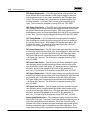
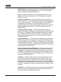
3.2.2
Fast Scan Controllers
Certain models of the Computing and Interactive controllers are
designed to execute the FST and control algorithms at a rate faster than
the normal one-quarter second (4 Hz). These models operate at
one-tenth second (10 Hz) and one-twentieth second (20 Hz) scan
rates.
These models of the regulatory controllers may be needed for
applications which require extremely fast response times to changing
process conditions, such as pressure override, etc.
The architecture of the fast scan controllers is identical to the standard
regulatory controllers. That is, the input/output scanning and FST
execution are performed in the same sequence, and many of the
trade-offs and constraints apply equally to all models of the regulatory
controllers.
Note
Since the FST is executed more frequently on the fast
scan controllers, the control algorithm must be
simpler when implemented in a fast scan controller in
order to avoid an overload condition. THE FAST SCAN
CONTROLLERS ARE NORMALLY LIMITED TO
SUPPORTING FEWER POINTS AND/OR FEWER FST
STEPS
THAN
THE
NORMAL
SCAN
RATE
CONTROLLERS.
The configuration device does not specifically
configure a fast scan version of the controllers.
Therefore, loading checks and point count limits are
not enforced by the configuration device.
For more detail concerning controller loading and estimation, please
refer to Appendix A, Loading and Sizing Calculations.
CE4.2:CL6211
Original Ć June 1990
Theory of Operation: Point Processing
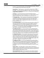
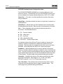
3.3
3Ć5
Direct Control Points
The IAC and Computing controllers provide control of continuous
processes through the use of direct control points (DCPs). The primary
components of each DCP are a Primary Control Algorithm (PCA), and a
station type. The PCA contains all of the intelligence (e.g., PID equations)
necessary to transform the DCP's inputs into outputs. The station type is
used to define the modes of operation (i.e., Manual, Automatic, etc.) that
are valid for the point. The PCA and station also contain several
functions, such as anti-reset windup, that can be configured to provide
proper control of the process. Some of the functions, such as restart
values, are common to both the PCA and station.
3.3.1
Primary Control Algorithms
Direct control points (DCPs) are available in five basic versions:
H
H
H
H
H
Manual Loader
Bias and Gain
High/Low Signal Selector
Proportional-Derivative with Bias
Proportional-Integral-Derivative
Five advanced DCPs are also available:
H
H
H
H
H
Error-Squared Proportional-Integral-Derivative
Notch Gain Proportional-Integral-Derivative
Adaptive Gain Proportional-Integral- Derivative
Control Sequence
Control Sequence with Bias
The names of these DCP versions are referred to as the Primary Control
Algorithms (PCAs). The details of these PCAs are described in the
following sections.
3.3.1.1
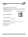
Manual Loader
The Manual Loader algorithm is the simplest type of DCP available in the
Controller, and allows for manual control of the Implied Valve Position
(IVP) of the DCP, i.e., the signal to the final control element will always
equal the IVP value that is entered. The manual loader also allows an
analog value to be monitored and displayed as the process variable of
the DCP, and allows a process set point to be entered. While the
process variable and set point of the manual loader DCP do not affect
Original Ć June 1990
CE4.2:CL6211
3Ć6
Theory of Operation: Point Processing
the IVP, they do provide the ability to establish a reference point for the
process (set point) and the ability to determine how the process variable
compares to that reference point for alarming purposes.
The modes of operation which are valid for the manual loader PCA,
manual (MAN) and Direct Digital Control (DDC), determine who is
allowed to change the IVP value. While in manual mode, the point
provides an operator with control of the IVP value. A host computer is
allowed to change the IVP value when the point is in DDC mode. The
operator is allowed to change the set point in either mode unless the set
point has been configured to track the process variable while in DDC
mode.
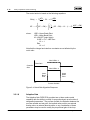
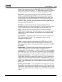
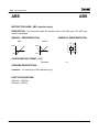
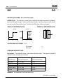
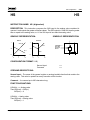
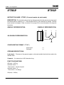
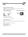
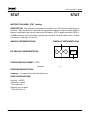
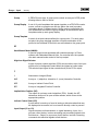
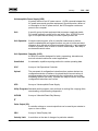
3.3.1.2
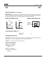
Bias & Gain
The Bias and Gain algorithm performs a linear transformation on the
process variable of the DCP to convert it to IVP. The algorithm adds the
bias value of the DCP to the process variable, and then multiplies the
result by the configured gain value. Both the bias value and the gain
value are tunable. Even though it has no effect on the IVP of the point, an
adjustable set point value is available as a reference value to be used for
alarms.
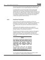
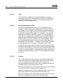
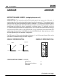
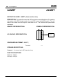
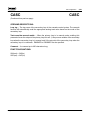
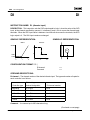
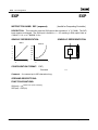
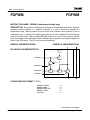
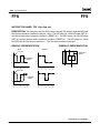
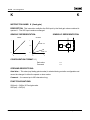
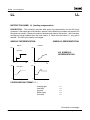
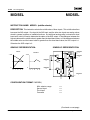
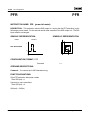
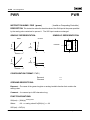
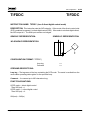
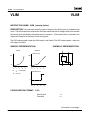
The two types of control action that are available for the Bias & Gain PCA
are Direct and Reverse. Direct action causes the IVP of the point to
increase if the PV increases. Reverse action causes the IVP to decrease
if the PV increases. The effects of bias and gain on the PV are shown in
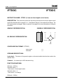
Figure NO TAG for both direct and reverse control action.
It should be noted that the bias value and gain value are tuned
independently of the valve action. For example, two parallel valves in a
split range operation could both be direct acting even though one valve
might be a fail open" type and the other one a fail closed" type.
The following equations describe the Bias and Gain algorithm:
Direct Action:
IVPĂ +Ă GAINĂ @Ă (PV ) LOOP BIAS) ) TBIAS
Reverse Action: IVPĂ +Ă 100 * GAINĂ @Ă (PV ) LOOP BIAS) ) TBIAS
Note that TBIAS is zero if transfer bias ramping is not enabled. Refer to
section NO TAG on page NO TAG.
CE4.2:CL6211
Original Ć June 1990
3Ć7
Theory of Operation: Point Processing
Direct Action
Reverse Action
100%
100%
IVP
IVP
GAIN = 1/2
BIAS = 50
GAIN = 1
BIAS = 0
0%
GAIN = 1
BIAS = 0
GAIN = 1
BIAS = -50
GAIN = 1/2
BIAS = 50
GAIN = 1
BIAS = -50
Process Variable
100%
0%
Process Variable
100%
Figure 3Ć1 . Effects of Bias & Gain
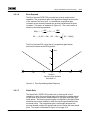
3.3.1.3
High/Low Signal Selector
The High/Low Signal Selector algorithm is used to select an analog value
from one of four process variable inputs when in automatic mode, and
pass that value through the algorithm so that it becomes the IVP of the
point.
The signal selector is typically used in override applications where its
process variable inputs are the outputs of other points. For proper
operation, the signal selector and its associated points must have the
same increase open/close settings (e.g., a point that is configured as
increase open must be connected to a signal selector that is increase
open).
The signal selector can be configured to select the input that results in
the highest IVP for the point, or the input that results in the lowest IVP for
the point. A HIGH signal selector selects the input that will cause the
highest IVP; LOW selects the lowest IVP. HIGH would be the highest
voltage for an increase-open valve and the lowest voltage for an
increase-close valve.
The signal selector allows for one to four inputs to be compared. The
signal value of the selected" input channel becomes the point's process
variable, and the process variable input to the alarms. The IVP is written
into the set point value of the point, and is also used as the set point
input to the alarms.
Original Ć June 1990
CE4.2:CL6211
3Ć8
Theory of Operation: Point Processing
3.3.1.4
Proportional-Derivative with Bias
The Proportional-Derivative with Bias (P/PD with Bias) PCA provides a
standard one or two mode control function. The P/PD with Bias PCA is
normally used as a PD controller, but it also allows the derivative term to
be tuned to zero to create a proportional-only controller.
The control algorithm can be viewed as a dual input, single output math
function whose output is derived from the periodic execution of a set of
positional control equations. The DCP's process variable is used as the
first input, the DCP's set point is used as the second input, and the result
of the control function becomes the IVP of the point.
The P/PD with Bias control algorithm is based on the following transfer
function:
K(T dĂs ) 1)
IVP(s)
Ă +Ă
aĂT dĂs ) 1
error(s)
where: Td = rate time constant
a = rate action limiter; 0.125
K = proportional gain
By using the intermediate term DN(s), the transfer function can be
rearranged to:
T Ăs ) 1
DN(s)
Ă +Ă d
aĂT dĂs ) 1
PV(s)
IVP(s)
Ă +Ă K
SP(s) * DN(s)
These equations can be represented in the time domain as:
DN(s)Ă +Ă T d dPV ) PV * aĂT d dDN
dt
dt
IVPĂ +Ă K(SP * DN)
The equations shown are for reverse acting loops. The signs of the SP
and DN terms are inverted for direct acting loops. Note that the SP term
has been isolated so that rate action occurs only on changes to the PV,
which is necessary to obtain good control action in response to set point
changes. Also note that the rate action has been filtered to prevent the
algorithm from over reacting to high frequency noise.
CE4.2:CL6211
Original Ć June 1990
Theory of Operation: Point Processing
3Ć9
The P/PD algorithm will also allow bias and transfer ramping bias to be
added. Refer to section NO TAG on page NO TAG. In this case, the final
equations become:
IVPĂ +Ă K(SP * DN) ) LOOPĂBIAS ) TBIAS
3.3.1.5
Proportional-Integral-Derivative
The Proportional-Integral-Derivative (PID) PCA provides one, two, or
three mode control capability based upon a positional control algorithm.
The PID PCA allows the proportional and derivative terms to be tuned to
zero, allowing the point to function as a PI, a PID, or an I-only controller.
Like the proportional-derivative with bias PCA, the PID control algorithm
can be viewed as a dual input, single output math function. The point's
process variable value is used as one input, the set point is the second
input, with the resulting output of the math function being the IVP of the
point.
The PID algorithm is based on the following transfer function:
K(T iĂs ) 1)(T dĂs ) 1)
IVP(s)
Ă +Ă
T iĂs(aĂT dĂs ) 1)
error(s)
where:
Ti = integral time constant
Td = rate time constant
a = rate action limiter; 0.125
K = proportional gain
By using an intermediate term, DN(s), the transfer function can be
rearranged to:
T Ăs ) 1
DN(s)
Ă +Ă d
aĂT dĂs ) 1
PV(s)
K(TiĂs ) 1)
IVP(s)
Ă +Ă
T iĂs
SP(s) * DN(s)
The equations can then be represented in the time domain as:
DN(s)Ă +Ă T d dPV ) PV * aĂT d dDN
dt
dt
R
IVPĂ +Ă K[(SP * DN) ) 1
Ti
Original Ć June 1990
ŕ (SP * DN)dt]
0
CE4.2:CL6211
3Ć10
Theory of Operation: Point Processing
Note that like the P/PD with Bias PCA, the set point term of the PID
algorithm has been isolated so that rate action occurs only on changes
to the PV, and that the rate action has been filtered to prevent the
algorithm from over reacting to high frequency noise. Again, the
equations shown are for reverse acting loops, and the signs of the SP
and DN terms are inverted for direct acting loops.
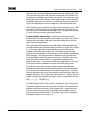
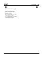
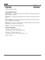
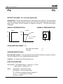
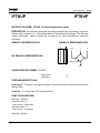
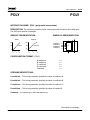
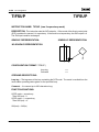
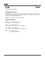
A feature of the PID PCA that is not shown in the control equations is the
concept of one half proportional bands" that establish when the point's
IVP will come off of its limits. As their name implies, the one half
proportional band limits are positioned on either side of set point, with
each limit one half of a control proportional band away from set point.
Once the IVP of a DCP is output limited, at which point the integral term
of the equation stops winding up, it will not come off the limit until the
process variable crosses its one half proportional band point. By design,
the valve position will be 50% from the limit when the process variable
crosses its set point.
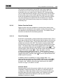
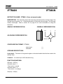
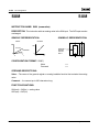
Figure NO TAG illustrates the one half proportional band concept. As an
example, one may consider the one half proportional bands of a DCP
with a gain of 10. The proportional band is 10%, with each one half
proportional band at 5% above and below the set point. If the set point
is 70%, the one half proportional bands will be at 65% and 75%.
Assuming the valve is closed and the IVP is at its low limit, as shown at
Point A, the valve will not start to open until the process variable
increases to 65% at Point B. When the process variable equals the set
point at Point C, the process variable will have moved 5% past the one
half proportional band limit at a gain of 10, which will cause the valve to
move 50%.
+1/2 P.B.
75%
70%
65%
Setpoint
- 1/2 P.B.
PV
C
50%
A
B
IVP
Figure 3Ć2. One Half Proportional Band Concept
One half proportional bands are built into each of the PID based
algorithms, and are valuable on high gain DCPs where the valve output
is at its output limit during a portion of the control cycle.
CE4.2:CL6211
Original Ć June 1990
Theory of Operation: Point Processing
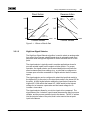
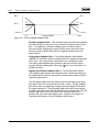
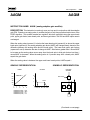
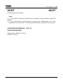
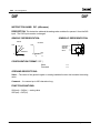
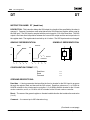
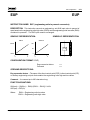
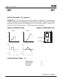
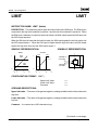
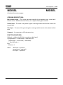
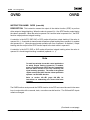
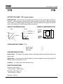
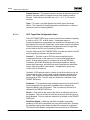
3.3.1.6
3Ć11
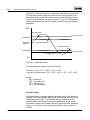
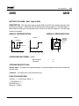
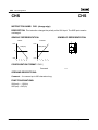
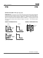
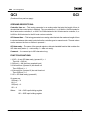
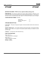
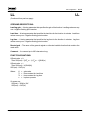
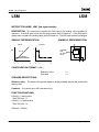
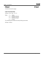
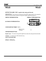
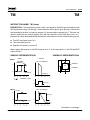
Error Squared
The Error Squared PI/PID PCA provides two or three mode control
capability. The proportional gain of the algorithm changes as a function
of the square of the error term, i.e. the effective proportional gain
increases as the deviation between the process variable and set point
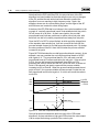
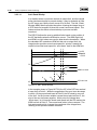
increases. This action is illustrated in Figure 3Ć3. The control action is
based on the following equations:
DN(s)Ă +Ă T d dPV ) PV * aĂT d dDN
dt
dt
IVPĂ +Ă K[Ă|SP * DN| @ (SP * DN) ) 1
Ti
R
ŕ (SP * DN)dt]
0
The Error Squared PCA, other than it's proportional gain feature,
performs the same as the PID algorithm.
30
Gain
20
10
-30
-20
-10
0
10
Deviation
Percent of Span Deviation
Base Gain of 1
20
30
Figure 3Ć3. Error Squared Algorithm Response
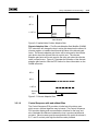
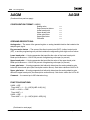
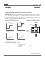
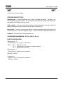
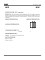
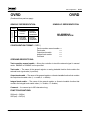
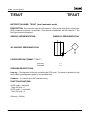
3.3.1.7
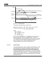
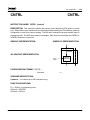
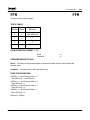
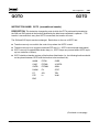
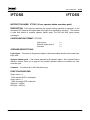
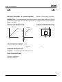
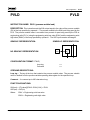
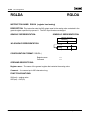
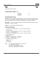
Notch Gain
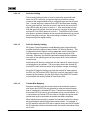
The Notch Gain PI/PID PCA provides two or three mode control
capability in which the proportional gain of the algorithm changes based
on the value of the process variable relative to it's upper and lower gain
break points. The base proportional gain is multiplied by the Notch Ratio
whenever the process variable is within the notch region established by
the break points. The proportional gain is unchanged whenever the
process variable is above the upper break point or below the lower break
point. This action is illustrated in Figure 3Ć4 on page 3Ć12.
Original Ć June 1990
CE4.2:CL6211
3Ć12
Theory of Operation: Point Processing
The control action is based on the following equations:
DN(s)Ă +Ă T d dPV ) PV * aĂT d dDN
dt
dt
R
ȱ
d(SP * DN)
IVPĂ +Ă KĂȧ(SP * DN) ) ŕ ǒ 1 @ (SP * DN) * K1 @ (1 * R)Ă
Ti
dt
Ȳ
0
where:
UBP= Upper Break Point
LBP= Lower Break Point
K1=ON/OFF Logic Switch
If UBP > PV > LBP Then
K1 = 1
Else
K1 = 0
Note that the integral and rate time constants are not affected by the
notch ratio.
Notch Ratio >1
Base Gain
Controller
Gain
Notch Ratio <1
Upper
Break
Point
Lower
Break
Point
0%
Process Variable
100%
Figure 3Ć4. Notch Gain Algorithm Response
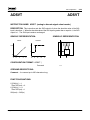
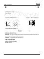
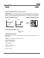
3.3.1.8
Adaptive Gain
The Adaptive Gain PI/PID PCA provides two or three mode control
capability with the ability to modify it's proportional gain as a function of
designated parameters. The process variable, the deviation between the
process variable and set point, the implied valve position, an external
analog value, an external discrete value, or any combination of these
parameters may be used to modify the proportional gain of the loop.
CE4.2:CL6211
Original Ć June 1990
Theory of Operation: Point Processing
3Ć13
There are two proportional gains associated with the adaptive gain PCA.
The controller base gain is the gain that is tuned into the controller and
modified by the adaptive gain control calculations. The active gain is the
actual gain used by the controller. Each adaptive gain variable changes
its adaptive gain factor for the loop. The total active gain is the product
of all of the adaptive gain factors multiplied by the nominal base gain.
The total active gain is limited by the Gain Limit configuration item. The
gain limit is a high limit when it is set above the base gain value and a
low limit when it is set below the base gain value. The gain limit provides
a hard" limit that the active gain cannot exceed.
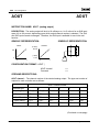
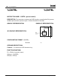
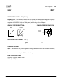
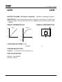
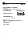
Process Variable Adaptive Gain Ċ When the active gain is being
modified by the process variable, it will change based upon the process
variable value, the value of the upper and lower break points, and the
upper and lower gain factors.
The upper and lower break points are adjustable values that divide the
process variable span into three regions as shown in Figure 3Ć5 on page
3Ć14. The lower gain factor determines the gain when the process
variable is below the lower break point. The farther below the break
point the process variable is, the more the process variable adaptive gain
factor changes. The upper gain factor determines the gain when the
process variable is above the upper break point. The farther above the
break point the process variable is, the greater the change in the
adaptive gain factor. The process variable active gain factor is 1.0 when
the process variable is between the upper and lower break points.
The resulting active gain changes linearly based on the difference
between the break point and the adapting variable. The rate of change
of the active gain is established by the respective gain factor. The gain
factor is defined as the ratio of the base gain to the active gain when the
adaptive variable is 10% of span from the break point. The gain factor is
used to calculate the adaptive gain factor, which is computed as follows:
AGF = 1 - [(1 - GF)(DEV)/10]
The adaptive gain factor is then used to calculate the loop's active gain.
A gain factor greater than one causes the active gain to increase as the
adaptive variable moves away from the break point. A gain factor less
than one causes the active gain to decrease as the adaptive variable
moves away from the break point. The effect of gain factor changes is
illustrated in Figure 3Ć5 on page 3Ć14.
Original Ć June 1990
CE4.2:CL6211
3Ć14
Theory of Operation: Point Processing
GF>1
GF>1
GF=1
GF=1
1>GF>0
1>GF>0
0%
Analog Variable
100%
Figure 3Ć5. Process Variable Adaptive Gain
Deviation Adaptive Gain Ċ The deviation signal (the difference between
process variable and set point) may be used to modify the loop's active
gain. The operation of deviation adaptive gain is similar to that of
process variable adaptive gain except that the upper and lower break
points are used to divide the positive to negative deviation span into
three sections.
Analog Value Adaptive Gain Ċ The Analog Adaptive Gain Modifier
(AAGM) FST instruction allows an analog value to change the active gain
of the loop. The analog value is assumed to be in engineering units.
The analog value adaptive gain operates in the same manner as the
process variable adaptive gain. See page 4 29 for more information on
AAGM instruction.
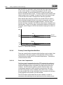
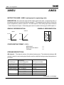
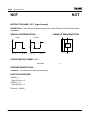
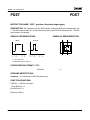
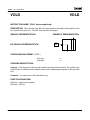
Implied Valve Position Adaptive Gain Ċ The Implied Valve Position
(IVP) adaptive gain function will change the loop's active gain based on
the relationship of the IVP to the upper and lower break points and their
respective gain factors.
The IVP adaptive gain factor will assume one of three values; the upper
gain factor value, the lower gain factor value, or unity. The IVP adaptive
gain factor will be set equal to the upper gain factor when IVP exceeds
the upper break point. The IVP adaptive gain factor will be set equal to
the lower gain factor when IVP falls below the lower break point. The IVP
adaptive gain factor will be set equal to the unity gain when IVP is
between the upper and lower break points. Figure 3Ć6 on page 3Ć15
illustrates the operation of the IVP adaptive gain function.
CE4.2:CL6211
Original Ć June 1990
Theory of Operation: Point Processing
3Ć15
GF>1
GF=1
1>GF>0
Lower
Break
Point
0%
Upper
Break
Point
100%
Valve Position
Figure 3Ć6. Implied Valve Position Adaptive Gain
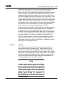
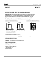
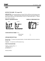
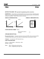
Discrete Adaptive Gain Ċ The Discrete Adaptive Gain Modifier (DAGM)
FST instruction will change the loop's active gain based on the value of a
discrete register or loadable function and the value of the discrete gain
factor. The discrete adaptive gain factor will be set equal to the discrete
gain factor when the discrete value is equal to one. The discrete
adaptive gain factor will be set equal to the unity gain when the discrete
value is equal to zero. Figure 3Ć7 illustrates the operation of the discrete
adaptive gain function. See the FST Section for more information on the
DAGM instruction.
GF>1
GF=1
1>GF>0
Discrete
Input
'0'
Time
'1'
Figure 3Ć7. Discrete Adaptive Gain
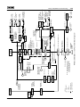
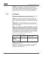
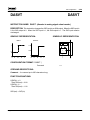
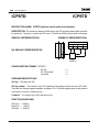
3.3.1.9
Control Sequence with and without Bias
The Control Sequence PCA provides a limited set of functions upon
which a user-defined algorithm may be based. The Control Sequence
PCA provides display and communications interface for the loop, and
also calculates the difference between the loop's process variable and
set point. Valve increase open/close adjustment, trip points for alarms A,
B, C, and D, and set point high/low limits are also provided.
Original Ć June 1990
CE4.2:CL6211
3Ć16
Theory of Operation: Point Processing
The Control Sequence PCA allows the user to customize the PCA
computation to perform any unique control algorithm. A minimum set of
standard features are provided by the CONTROL and STATION FST
function blocks when the Control Sequence PCA type has been
selected. These standard features include Operating Parameter display
and communications support (PV, SP, IVP, Mode, Bias, and Ratio),
parameter limiting, alarming, tracking, etc.
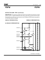
3.3.1.9.1
FST Configuration using Control Sequence PCA
The user may program any set of computations between the CONTROL
and STATION FST blocks, using the standard FST functions. This is
different from the normal" PCA types, which will NOT allow the user to
program any FST functions between the CONTROL and STATION FST
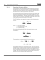
blocks. These configuration restrictions are as follows:
Standard PCA Types
Control Sequence PCA Types
CNTRL
CNTRL
Only feedforward
FST function blocks
allowed here.
Any FST function
EXCEPT feedforward
allowed here.
STAT
STAT
Notice that the FST will not allow the user to configure any feedforward
FST function block into this loop when the Control Sequence PCA type is
selected. The user must accommodate any feed forward action required
by including the FST logic necessary to support that feed forward action.
3.3.1.9.2
Equations for CONTROL FST Function Block
The Signal Value Analog (SVA) output of the CONTROL FST function
block for a Control Sequence PCA type is equal to the loop deviation
error (PV minus SP for direct action, or SP minus PV for reverse action).
The SVA output value is always a percent deviation signal, computed
after the PV and SP have been converted to percent on the Engineering
Units scale. The Signal Value Discrete (SVD) output of the CONTROL
FST function block is set to zero when the PCA is being initialized (such
as after a power fail restart, or after any mode change is received), and is
set to one whenever the PCA is performing all normal forward
CE4.2:CL6211
Original Ć June 1990
Theory of Operation: Point Processing
3Ć17
calculations. (The configuration engineer can take advantage of this
SVD output signal to initialize or balance any FST computations that are
being performed in place of the standard PCA computations.)
The standard PCA functions such as SP limiting, SP velocity limiting, SP
tracking, etc. are all supported by the Control Sequence PCA types when
the CONTROL FST function block is executed.
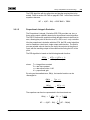
3.3.1.9.3
Equations for STATION FST Function Block
The Signal Value Analog (SVA) input to the STATION FST function block
for a Control Sequence PCA type must be a percent value equal to the
valve position (current signal) to be sent to the final control element,
exclusive of any Bias that is present on the loop. The equations for the
STATION FST function block are:
SVA(out) = SVA(in) + Bias + Transfer Bias
for an increase open valve:
IVP = SVA(out)
for an increase close valve:
IVP = 100% - SVA(out)
The Signal Value Discrete (SVD) output of the CONTROL FST function
block is set equal to the state of the deviation alarm (Alarm A).
The standard STATION functions such as IVP limiting, output tracking,
Mode limiting, alarming, Transfer Bias ramping, Bias balancing (when
Transfer Bias ramping is disabled), and Watch Dog Timer for DDC or
Supervisory modes are all supported by the Control Sequence PCA
types when the STATION FST function block is executed.
3.3.2
Station Types
The station type of a direct control point is defined by the modes that are
valid for it (e.g., an Automatic/Manual station type). Several
combinations of station types are valid, and are defined as follows: MAN,
AUT/MAN, AUT/MAN/RSP, AUT/MAN/SUP, AUT/MAN/DDC, MAN/DDC,
AUT/MAN/DDC/SUP.
The mode of operation for a direct control point primarily determines who
can adjust the set point and IVP. The different modes that are available
are: Manual (MAN), Automatic (AUT), Remote Set Point (RSP),
Supervisory (SUP), and Direct Digital Control (DDC). The mode of a
point can be changed by an FST or an operator at a PROVOX console or
operator station.
Original Ć June 1990
CE4.2:CL6211
3Ć18
Theory of Operation: Point Processing
3.3.2.1
Modes
Manual Mode (MAN): In MAN mode, the operation of the Primary
Control Algorithm (PCA) is suspended, and the operator is allowed to
adjust the IVP. If output tracking is enabled, and output tracking override
in manual mode is enabled, the IVP is dictated by the track signal value.
If the set point tracking in manual mode option is enabled, then the
operator entered SP is overridden by the track signal value. Note that the
set point has no effect on the IVP. The bias value can also be changed.
Automatic Mode (AUT): While in AUT mode, the set point and the bias
(if applicable) are entered by the operator. All of the functions associated
with the PCA are then executed, which determines the final IVP unless
output tracking is enabled.
Remote Set Point Mode (RSP): RSP mode is similar to AUT in that the
PCA functions, or output tracking if enabled, determine the final IVP. In
RSP mode, the set point is received through a configured analog value,
The bias value can still be entered by the operator.
Supervisory Mode (SUP): The SUP mode is similar to the RSP mode
except that in SUP mode, the set point is received from a host computer.
and is not operator adjustable. The bias value can still be entered by the
operator.
Direct Digital Control Mode (DDC): In DDC mode, the operation of the
PCA is suspended, and a host computer controls the IVP. The operator
can still enter the set point unless the set point tracking in DDC mode is
enabled, in which case the operator entered set point is overridden by
the track signal value.
3.3.2.2
Mode Transfers
When a point is involved in a mode transfer, it is common for some or all
of the operating data to change. The mode transfer logic for each direct
control point guarantees that mode changes are bumpless and
balanceless.
Any Mode to Manual: The present value of the IVP and set point are
maintained until the operator initiates a change, unless Set Point Tracks
PV in MAN mode is enabled.
Manual or DDC to Automatic: The present value of all operating data,
including the set point and IVP, is used to initialize the PCA at the
beginning of the transfer. If enabled, transfer bias ramping begins
ramping the IVP from the value at the time of transfer to the value
calculated by the PCA.
CE4.2:CL6211
Original Ć June 1990
Theory of Operation: Point Processing
3Ć19
Manual to RSP: The present value of all operating data is used at the
beginning of the transfer, with the exception of the set point, which is
now input from the RSP input. The PCA initialization and transfer bias
ramping (if enabled), are the same as in the manual or DDC to automatic
transfer.
Automatic to RSP: During this transfer, the execution of the PCA is
re-initialized because the source of the set point has changed. This is
done to prevent a bump in the IVP due to a difference between the local
set point and the remote set point. Transfer bias ramping, if applicable,
will be performed on the output.
RSP or Supervisory to Automatic: For this transfer, the set point
remains at its last established value until it is changed by the plant
operator. The IVP will not change.
Manual to Supervisory: The present value of all operating data is used
at the beginning of the transfer, with the exception of the set point, which
is now supplied by a host computer. The IVP will not be changed unless
transfer bias ramping is enabled.
Automatic to Supervisory: During this transfer, the PCA is re-initialized
because the set point source has changed. This is done to prevent a
bump in the IVP due to a difference between the local set point and the
set point supplied by the host computer. Transfer bias ramping will be
performed on the output if it is enabled; otherwise, the IVP will not
change.
Manual or Automatic to DDC: This transfer causes the IVP to hold until
changed by a host computer. The set point will not change unless set
point tracking in DDC mode is enabled, in which case the set point will
track the process variable.
3.3.3
Direct Control Point Details
3.3.3.1
Primary Control Algorithm Function Details
Primary Control Algorithm functions are items available for use with direct
control points (DCPs) that are configured to set up proper control of the
process. Their use depends on the requirements of the process. The
details of these functions are described in the following sections.
Original Ć June 1990
CE4.2:CL6211
3Ć20
Theory of Operation: Point Processing
3.3.3.1.1
Anti-Reset Windup
In a situation where a point has reached an output limit, and the integral
action has been stopped to prevent windup, it may be desirable to have
the IVP move very rapidly once it comes off of its limit. The Anti-Reset
Windup (ARW) feature provides the option of having the integral term of
a DCP unwind at a speed 16 times the normal, tuned reset speed. This
feature reduces the effects of reset windup on process variable
overshoot.
The PID PCA allows the user to establish limits based on the position of
the IVP that define when the ARW action occurs. The ARW High Limit
and ARW Low Limit values are used to determine the boundaries. When
the calculated IVP exceeds an ARW limit but not an output limit, the
integral action provides normal reset speed for windup" towards the
output limit and fast reset speed for wind down" back to the ARW limit.
+1/2 P.B.
Setpoint
- 1/2 P.B.
PV
ARW Low Limit
C
A
D
B
IVP
IVP Low Limit
Figure 3Ć8. Anti-Reset Windup
In the example shown in Figure NO TAG, the IVP of the DCP has reached
a lower limit at Point A. When the magnitude of the error term decreases
to within 1/2 the proportional band at Point B, the IVP starts to come off
of the limit. As the process variable crosses the set point at Point C, the
sign of the error becomes negative. At this point, the integral term
winds down" at 16 times the tuned reset speed until the IVP reaches the
ARW low limit at Point D. The normal reset action is then resumed. The
fast reset speed quickly changes the magnitude of the integral term,
resulting in less process variable overshoot.
CE4.2:CL6211
Original Ć June 1990
Theory of Operation: Point Processing
3.3.3.1.2
3Ć21
Set Point Limiting
The set point limiting function is used to restrict the upper and lower
limits of a DCP's set point, and prevent that set point from moving
outside of the range established by a configured high and low set point
limit. If a new set point is entered for the DCP, and that value exceeds
the set point high limit, then the set point is set to that limit, and the SP
High (SPHI) alarm bit is set to a value of 1. If the new set point is less
than the set point low limit, then the set point is set equal to that limit,
and the SP Low (SPLO) alarm bit is set to 1. The SPHI and SPLO alarm
bits allow for operator indication at the console that either high or low set
point limiting has occurred. Set point limiting is available on all PCAs
except the high/low signal selector.
3.3.3.1.3
Set Point Velocity Limiting
All Primary Control Algorithms except Manual Loader, Signal Selector,
and Bias and Gain support a feature called SP Velocity Limiting". This
configuration choice enables a tuning parameter which is then used to
limit the maximum rate of change of the SP value used by the PCA,
internally. Effectively, this limits the allowable change that the operator
can make to the operating point of the process when in the Automatic
control mode.
Note that the SP Velocity Limiting will limit the internal SP value, which is
not displayed to the operator. The user simply selects the desired SP,
and the PCA then limits the results of the operator change accordingly.
Since the SP Velocity Limiting only limits the internal SP value used by
the PCA, the FST function SPLD (Set Point Load) will load the SP value
selected by the operator, and the SVA output of the SPLD FST function
will not reflect the velocity limited SP used by the PCA.
3.3.3.1.4
Transfer Bias Ramping
Bumpless transfers from the manual mode to the automatic mode on
bias & gain and P/PD PCAs are achieved by either an internal transfer
bias or a backward calculated DCP bias. Transfer bias ramping allows
the normal DCP bias value to be maintained during a mode transfer. If it
is not enabled, the normal DCP bias value is changed during the mode
transfer and must be reset after the transfer has been completed.
When transfer bias ramping is enabled, the internal transfer bias value is
back calculated to achieve a bumpless mode transfer. For example, if
the IVP was 60% while the DCP was in manual mode, and the IVP should
be 50% after the switch to automatic mode, the transfer bias value will be
set to 10%.
Original Ć June 1990
CE4.2:CL6211
3Ć22
Theory of Operation: Point Processing
After the DCP is in automatic mode, the transfer bias value ramps linearly
to zero, which causes a corresponding change in the IVP. In the
previous example, this would cause the IVP to ramp from 60% back
down to the desired value of 50%. The time required for the transfer bias
value to ramp to zero is tunable. A ramp time of zero will cause a bump
in the IVP when the mode is changed from manual to automatic.
When transfer bias ramping is disabled, the normal DCP bias value is
back calculated during a transfer from manual to automatic mode, and
set to a value that will achieve a bumpless transfer. Once the mode
transfer has been completed, the DCP bias value can be changed to any
desired value. Figure 3Ć9 on page 3Ć22 shows the effects of a manual to
automatic mode change on the bias and transfer ramping bias values of
a DCP.
100%
IVP
60%
Old IVP
Desired IVP
50%
TBIAS
10%
0%
Figure 3Ć9. Transfer Bias Ramping
3.3.3.2
Primary Control Algorithm Modifiers
There are several function sequence table functions, such as dead-time
compensation, that act as primary control algorithm (PCA) modifiers.
These functions modify the PCA for specific applications. Descriptions
of these functions follow.
3.3.3.2.1
Dead-time Compensation
The Dead-time Compensation function (DTC) extends the continuous
control capability of a direct control point to include processes having
significant reaction lag time compared to the dominant process time
constant. The DTC function performs a Smith Predictor dead-time
compensation algorithm, which models the process as a first order
process having a gain, a time constant, and a dead-time. A model
process variable value is then calculated, which is passed to the primary
control algorithm as a pseudo-process variable.
The DTC function compensates the process variable in a series of
calculations after alarming has been performed and the actual process
CE4.2:CL6211
Original Ć June 1990
Theory of Operation: Point Processing
3Ć23
variable has been stored as the point's process variable attribute. The
first step is calculating a model process variable using the Model
Dead-time value. This model process variable is then used to calculate
the model error by taking the difference between the model process
variable and the actual process variable. The model error value is then
corrected by adjusting either the model gain or the model bias, a choice
which is dependent upon whether the primary process load disturbance
modifies the process gain or the process bias. A second model process
variable, which is the model of the process variable as it would appear
without dead-time, is then calculated. This new model process variable
also takes into account the Model Error, and is the process variable
which is output from the compensation function to the PCA.
If the model process variable accurately reflects the actual process, then
the model output cancels the process feedback signal. Under these
conditions, the closed loop characteristics are only a function of the
controller and the process model without dead-time. An improvement
in control is then possible because of the elimination of dead-time from
the model equation. This option is available only with the PID PCA.
The DTC function allows for a reset to be used to disable the function.
When the reset value is a logic 1, the function is disabled. When the
reset value is set back to a logic 0, the function re-initializes and starts
performing its compensation routine.
3.3.3.2.2
Override
The override function causes the output of the control algorithm to
perform either output or integral tracking. When output tracking is
enabled, the control algorithm output tracks the specified track signal
value when the point is in auto, RSP, SUP or DDC modes. This function
also allows for output tracking to override manual mode. When output
tracking is disabled and integral tracking is enabled, an analog value is
read in from the specified track signal value and is substituted for the
calculated integral term in the control algorithm.
Note
To avoid loop windup in override control applications
for which integral tracking (operand 4) is enabled,
place a FIL function and a RGST function immediately
after the AOUT function of the loop containing the
signal selecting operation. The name of the general
register used by the RGST function is then specified in
operand 2 of the OVRD function. Refer to section
NO TAG (page NO AG)
T
for instructions on
determining the correct filter time constant. Refer to
the FST configuration section for more details on the
individual functions.
Original Ć June 1990
CE4.2:CL6211
3Ć24
Theory of Operation: Point Processing
3.3.3.2.3
Track
The track function modifies the tracking characteristics of a point. It
causes the output of the control algorithm to track the specified track
signal value when tracking is enabled. This function also allows for
tracking to override manual mode.
3.3.3.2.4
Gas Chromatograph Interface
Gas Chromatograph Interface (GCI) performs a sample and hold
operation on the process variable input whenever the GCI data ready
input makes a 0 to 1 transition. The GCI function will enable integral
control action for the length of time specified (controller on-time) after
the GCI data ready input has made a 0 to 1 transition. The controller
integral action is then held after the controller on-time has elapsed.
There will be no change to the output of the control algorithm when the
integral action is held because the GCI function is holding its output
which would be the process variable to the control algorithm. When
used, the feedforward function is active when the control algorithm is
being held by the GCI function. Therefore, the output from the station
will change when there is a change in feedforward control action.
If a new GCI data ready input is not received by the time the specified
timeout time has elapsed, the GCI function sets the point to the manual
mode and sets the discrete signal value output of the GCI function block
to a logic 1 to indicate timeout. A new data ready trigger will reset the
discrete signal value output to a logic 0, but will not automatically switch
the mode.
3.3.3.2.5
Cascade
The cascade function provides cascade control linkage between two
direct control points; the second of which must have remote set point
mode. The implied valve position (IVP) of the primary loop is
automatically placed into the set point of the secondary loop when the
secondary loop is in the remote set point mode.
When the secondary loop is in the manual mode, the IVP of the primary
loop tracks the process variable of the secondary loop.
When the secondary loop is in the local automatic mode, the IVP of the
primary loop tracks the local set point of the secondary loop.
When the secondary loop is in the remote set point mode, the IVP of the
primary loop becomes the set point of the secondary loop.
CE4.2:CL6211
Original Ć June 1990
Theory of Operation: Point Processing
3Ć25
The primary loop will perform normal PID control action when the
secondary loop is in the remote set point mode and the IVP of the
secondary loop is not output limited. When the IVP of the secondary
loop is output limited and a change in the primary loop's IVP will cause
the secondary loop to drive harder against its output limit, the integral
action will be disabled in the primary loop. This will prevent the primary
loop from winding up its output when the secondary loop is already
output limited in the direction the primary loop is tending to drive the
secondary loop.
3.3.3.3
Station Function Details
Station functions are items available for use with direct control points
(DCPs) that are configured to set up proper control of the process. Their
use depends on the requirements of the process. The details of these
functions are described in the following sections.
3.3.3.3.1
Alarm Processing
Each DCP is automatically configured with three standard alarms. Two of
these alarms (Alarm B and C) are absolute high/low alarms, the third one
(Alarm A) is a deviation alarm. These alarms are based on the process
variable and set point of the DCP. Two function sequence table (FST)
function blocks must be used to activate discrete outputs with the alarm
states. The desired alarm must first be loaded into the discrete signal
value using the Alarm Monitor Load (ALMLD) function (page 4 42). The
discrete signal is then directed to the discrete output using the Discrete
Output (DO) function (page 4 64). When the alarm is set, the
configured discrete output will be set to 1. When the alarm is cleared,
the configured discrete output will be set to 0. To obtain reverse logic, a
logical inverse (NOT) function (page 4 128) can be placed between the
ALMLD and DO functions.
In addition, alarm D is available as a user-defined alarm. It is
implemented using the Alarm Store (ALMST) FST function (page 4 44).
When the discrete signal value input to the ALMST function is a logic 1,
the alarm is set. When the discrete signal value input to the ALMST
function is a logic 0, the alarm is not set.
Absolute Alarms
Absolute alarms monitor the process variable of a point, and may be
individually configured as high or low alarms. If an absolute alarm is
configured as a high alarm and the value of the process variable goes
above the alarm trip point, then the alarm is set. When the process
variable falls below the level defined by the trip point minus the
deadband, the alarm is cleared.
Original Ć June 1990
CE4.2:CL6211
3Ć26
Theory of Operation: Point Processing
Similarly, if an absolute alarm is configured as a low alarm and the value
of the process variable goes below the trip point, then the alarm is set.
When the process variable increases above the level defined by the trip
point plus the deadband, the alarm is cleared. Figure 3Ć10 illustrates the
relationship between the process variable, the alarm trip points and the
deadband.
100%
High Alarm Set
High Trip Point
Deadband{
Monitored
Attribute
High Alarm Cleared
Low Alarm Cleared
Deadband{
Low Trip Point
Low Alarm Set
0%
Figure 3Ć10. Absolute Alarms
The absolute alarm equations are shown below:
The alarm is set if: PV >= HTP or PV <= LTP
The alarm is cleared when: PV < ( HTP - DB ) or PV > ( LTP + DB )
Where:
DB = deadband
HTP = high trip point
LTP = low trip point
PV = process variable
Deviation Alarm
A deviation alarm is triggered when the absolute value of the difference
between the process variable and the set point exceeds the value of the
deviation alarm trip point. The deviation alarm is cleared when the
absolute difference between the process variable and the set point is
less than the value of the deviation alarm trip point minus the deadband.
Figure 3Ć11 shows the points at which the deviation alarm is set and
cleared.
CE4.2:CL6211
Original Ć June 1990
Theory of Operation: Point Processing
3Ć27
100%
Deviation Alarm Set
Deviation Limit
Deadband{
Monitored
Attribute
Deviation Alarm Cleared
Deviation Alarm Cleared
Deadband{
Reference or
Set Point Value
Deviation Limit
Deviation Alarm Set
0%
Figure 3Ć11. Deviation Alarms
The deviation alarm equations are shown below:
The alarm is set if: PV >= ( SP + DTP ) or PV <= ( SP - DTP )
The alarm is cleared when: PV < ( SP + DTP - DB ) or
PV > ( SP - DTP + DB )
Where:
DB = deadband
DTP = deviation trip point
SP = set point
PV = process variable
Alarm D is a user defined alarm. It is implemented using the Function
Sequence Table (FST) Alarm Store (ALMST) function . When the
Discrete Signal Value input to the ALMST function is a logic 1, the alarm
is set. When the Discrete Signal Value input to the ALMST function is a
logic 0, the alarm is not set. Refer to the FST section of the
Configuration Manual for details on the ALMST function.
3.3.3.3.2
Output Limiting
The output limiting function, which is available on all PCA types, is used
to prevent the IVP of a point from exceeding a configured high or low
limit. If the IVP value generated by the station function exceeds the
configured IVP high limit, then the IVP is set to that limit and the Valve
Output High (VOHI) alarm bit is set to a value of 1. If the IVP is less than
the configured IVP low limit, then the IVP is set to that limit and the Valve
Output Low (VOLO) alarm bit is set to 1. The VOHI and VOLO alarm bits
allow for operator indication at the console that either high or low output
limiting has occurred.
Original Ć June 1990
CE4.2:CL6211
3Ć28
Theory of Operation: Point Processing
3.3.3.3.3
Watchdog Timer
Watchdog timer allows the direct control point to be placed in a specified
backup mode if an update from a console or computer is not received
before the specified time interval and the watchdog timer alarms. It can
only be used with a station type that supports SUP or DDC modes.
3.3.3.4
Functions Common to Primary Control Algorithm and Station
Both the primary control algorithm and the station contain some
functions that are common in theory. These functions are restart values
and set point tracking which are described in the following sections.
3.3.3.4.1
Restart Values
There are several direct control point parameters that have configurable
restart values that may be used if the controller is restarting from a power
failure or a download. In addition to the restart values, the parameters
may also restart from the last value established before a shutdown of the
controller. The parameters which have configurable restart values are the
Set Point (SP), the Implied Valve Position (IVP), the operating mode
(MODE), the bias (BI), and ratio. Indirect Control Point (ICP) reference
values will automatically restart at the last value when a power failure
occurs.
Restart Value Storage
The restart values are retained in non-volatile memory (NVM). Power
fail restart will recall these values from NVM. The restart from last values
are updated in NVM once a minute if the values have changed
significantly. The required amount of change before the NVM value is
updated is 5% of span for set point, bias, IVP and ICP reference values.
The required amount of change before the NVM value is updated is an
absolute change of 0.12 for the ratio value. Mode is updated upon any
change.
Restart After a Power Failure
After a power failure, when restart from last value is specified, the restart
parameters are set to the last value established before the power failure.
When a specific restart value is defined, that value is used as the restart
value after power failure.
CE4.2:CL6211
Original Ć June 1990
Theory of Operation: Point Processing
3Ć29
Restart After a Download
After a download, when restart from last value is specified, the following
restart parameters are set to their failsafe values; set point = 0%,
bias = 0%, and ratio = 1. When a specific restart value is defined for
these parameters, that value is used. Mode always restarts at manual
after a download regardless of the defined restart value. The restart of
the IVP is described below.
The restart value of the IVP depends on whether the corresponding point
was previously configured. If the point was not previously configured
and restart from last value is specified, the IVP is set to 0%, and if a
predefined restart IVP value is specified, that value is used.
If the point was previously configured, then the point holds the last value
prior to download even if a predefined restart value is specified. When
the increase open/close setting of the point is changed, the
communicated IVP value is inverted (refer to the following example).
Example - The point was originally increase open, IVP was 75% and the
current output was 16 mA. The point was changed to increase close.
The new IVP value is 25% and the current output remains at 16 mA.
3.3.3.4.2
Set Point Tracking
Set point tracking is an optional way for a PCA to obtain its set point. The
set point can be configured to track the process variable when the point
is in DDC or manual mode. If set point tracking in DDC mode is enabled
and the point is in DDC mode, then the set point is set equal to the
process variable value. If set point tracking in manual mode is enabled
and the point is in manual mode, then the set point is once again set
equal to the process variable value.
Set point tracking in manual mode is available for all PCAs except the
bias and gain and the high/low signal selector, which effectively performs
set point tracking all of the time. Likewise, set point tracking in DDC
mode is available only if DDC is a valid mode for the point's configured
station type.
3.3.4
Direct Control Point Diagrams
The diagrams on the following pages illustrate the processing of the
various combinations of PCAs and station types.
Original Ć June 1990
CE4.2:CL6211
OUTPUT
TRACK
LOGIC
CE4.2:CL6211
S
OPERATE
(O)
DISCRETE SIGNALS
CONTROLLER
CURRENT
OUTPUT
INCREASE OPEN/CLOSE (T)
DEVIATION
ALARM
NOTE: ONLY ONE
DEADBAND MAY BE
SPECIFIED FOR ALL
THREE ALARMS.
TRIP POINT (T)
DEADBAND (T)
ALARM
B
SP HIGH LIMIT (T)
SP LOW LIMIT (T)
SS
Manual Loader Controller Block Diagram
VALVE
ACTION
S
ANALOG SIGNALS
TUNE
IVP (0)
IVP HIGH LIMIT (T)
IVP LOW LIMIT (T)
SS
(T)
TO OPERATOR
STATION AND
DATA HIGHWAY
SET POINT
LIMITS
MANUAL OUTPUT (O)
FROM CONSOLE OR
OPERATOR STATION
OUTPUT
TRACKING/NORMAL ?
(O)
S
IVP
LIMITS
OUTPUT
TRACKING
OUTPUT
TRANSFER
YES OR NO (C)
RESTART IVP (T)
SS
NOTES:
(C) CONFIGURE
S
RESTART
LAST IVP
LOCAL SET POINT (O)
FROM CONSOLE OR
DATA HIGHWAY
SET POINT
TRANSFER
SP (0)
DEVIATION
HIGH OR LOW (C)
TRIP POINT (T)
DEADBAND (T)
SS
INCREASE
OPEN/CLOSE (T)
S S
TO OPERATOR
STATION AND
DATA
HIGHWAY
YES OR NO (C)
RESTART SP (T)
YES OR NO (C)
S
RESTART
LAST SP
SP TRACKS
IN MAN
PV (O)
HIGH OR LOW (C)
TRIP POINT (T)
DEADBAND (T)
S SS
ALARM
C
S SS
OUTPUT
TRACKING
OVERRIDES
MANUAL? (C)
TO OPERATOR
STATION AND
DATA HIGHWAY
PROCESS
VARIABLE
ALARM C (0)
DEVIATION
ALARM (0)
ALARM B (0)
OR
ALARM B OR C (0)
am
VALVE
ACTION
TRACK
CONTROL
TRACK
VALUE
Figure 3Ć11Ć1. Manual Loader MAN Loop Point Block Diagr
TO OPERATOR
STATION AND
DATA HIGHWAY
TO DATA
HIGHWAY
TO
OPERATOR
STATION
TO DATA
HIGHWAY
3Ć30
Theory of Operation: Point Processing
Original Ć June 1990
Original Ć June 1990
TUNE
OPERATE
(T)
(O)
INCREASE OPEN/CLOSE (T)
S
Manual Loader MAN/DDC Controller Block Diagram
CONTROLLER
CURRENT
OUTPUT
S
DISCRETE SIGNALS
VALVE
ACTION
SS
ANALOG SIGNALS
CONFIGURE
(C)
IVP HIGH LIMIT (T)
IVP LOW LIMIT (T)
OUTPUT TRACKING/NORMAL (O)
S
IVP (0)
SS
IVP
LIMITS
YES OR NO (C)
RESTART IVP (T)
SP HIGH LIMIT (T)
SP LOW LIMIT (T)
MODE
LOGIC
WATCHDOG
TIMER
RESET
TO OPERATOR STATION
AND DATA HIGHWAY
DEVIATION
ALARM (0)
ALARM B (0)
OR
ALARM B OR C (0)
ALARM C (0)
TO OPERATOR
STATION AND
DATA HIGHWAY
TO DATA
HIGHWAY
TO
OPERATOR
STATION
TO DATA
HIGHWAY
TO OPERATOR STATION
AND DATA HIGHWAY
MODE CONTROL
FROM CONSOLE OR
OPERATOR STATION
YES OR NO (C)
TIMEOUT TIME (T)
RESTART LAST MODE? (C)
RESTART MODE (T)
NOTE: ONLY ONE DEADBAND MAY BE
SPECIFIED FOR ALL THREE ALARMS.
DDC CONTROL FROM DATA HIGHWAY
RESTART
LAST IVP
SET POINT
LIMITS
S S
OUTPUT
TRACKING
OUTPUT
TRANSFER
SET POINT
TRANSFER
SP (O)
S S
TO OPERATOR
STATION AND
DATA HIGHWAY
MANUAL OUTPUT (O)
FROM CONSOLE OR
OPERATOR STATION
INCREASE
OPEN/
CLOSE (T)
S
VALVE
ACTION
LOCAL
SET POINT (O)
FROM CONSOLE OR
DATA HIGHWAY
S
YES OR NO (C)
RESTART SP (T)
DEVIATION
TRIP POINT (T)
DEADBAND (T)
DEVIATION
ALARM
SS
OUTPUT TRACKING
OVERRIDES
MANUAL? (C)
YES OR NO (C)
SP TRACKS
IN DDC
HIGH OR LOW (C)
TRIP POINT (T)
DEADBAND (T)
ALARM
B
S SS
RESTART
LAST SP
YES OR NO (C)
S
SP TRACKS
IN MAN
HIGH OR LOW (C)
TRIP POINT (T)
DEADBAND (T)
ALARM
C
S SS
TRACK
CONTROL
TO OPERATOR
STATION AND
DATA HIGHWAY
PV (O)
PROCESS
VARIABLE
Figure 3Ć11Ć2. Manual Loader MAN/DDC Loop Point Block Diagram
NOTES:
OUTPUT
TRACK
LOGIC
TRACK
VALUE
Theory of Operation: Point Processing
3Ć31
S SS S
CE4.2:CL6211
OUTPUT
TRACK
LOGIC
CE4.2:CL6211
OPERATE
DISCRETE SIGNALS
CONTROLLER
CURRENT
OUTPUT
INCREASE OPEN/CLOSE (T)
Bias and Gain Controller Block Diagram
VALVE
ACTION
S
ANALOG SIGNALS
TUNE
SS
(O)
IVP (0)
IVP HIGH LIMIT (T)
IVP LOW LIMIT (T)
IVP
LIMITS
S
TO OPERATOR
STATION
BIAS
DISPLAY
TO OPERATOR
STATION AND
DATA HIGHWAY
TO DATA
HIGHWAY
TO
OPERATOR
STATION
TO DATA
HIGHWAY
BIAS
VALUE
TO DATA
HIGHWAY
BIAS VALUE (O)
TO OPERATOR
STATION AND
DATA HIGHWAY
MODE CONTROL
FROM CONSOLE
OR DATA HIGHWAY
RESTART LAST
MODE? (C)
RESTART MODE (T)
MODE (O)
YES OR NO (C)
RAMP TIME (T)
MODE
LOGIC
YES OR NO (O)
TRANSFER
RAMPING
S
(T)
SS
TO DATA HIGHWAY
S
OUTPUT TRACKING/
NORMAL? (O)
SS
CONFIGURE
YES OR
NO (C)
RESTART
IVP (T)
S
MANUAL OUTPUT (O)
FROM CONSOLE OR
OPERATOR STATION
RESTART
LAST IVP
S S
NOTES:
S
S
OUTPUT
TRACKING
OUTPUT
TRANSFER
S
SP (O)
SP HIGH LIMIT (T)
SP LOW LIMIT (T)
TRIP POINT (T)
DEADBAND (T)
DEVIATION
ALARM
DEVIATION
ALARM (0)
S
TO OPERATOR
STATION AND
DATA HIGHWAY
SET POINT
LIMITS
REVERSE OR DIRECT (T)
DEVIATION
HIGH OR LOW (C)
TRIP POINT (T)
DEADBAND (T)
ALARM
B
ALARM B (0)
OR
ALARM B OR C (0)
ALARM C (0)
Figure 3Ć11Ć3. Bias and Gain Loop Point Block Diagram
(C)
S
INCREASE
OPEN/CLOSE (T)
S S
VALVE
ACTION
ADD
RAMPING
CONTROL
ACTION
S
LOCAL SET POINT (O)
FROM CONSOLE OR
OPERATOR STATION
YES OR NO (C)
RESTART SP (T)
S
SET POINT
TRANSFER
RESTART
LAST SP
BIAS VALUE (O)
RESTART LAST
BIAS? (C)
RESTART
BIAS (T)
GAIN VALUE (T)
S S
GAIN
BIAS
HIGH OR LOW (C)
TRIP POINT (T)
DEADBAND (T)
NOTE: ONLY ONE
DEADBAND MAY BE
SPECIFIED FOR ALL
THREE ALARMS.
ALARM
C
S SS
OUTPUT
TRACKING
OVERRIDES
MANUAL? (C)
TO OPERATOR
STATION AND
DATA HIGHWAY
PV (O)
PROCESS
VARIABLE
S SS
TRACK
CONTROL
TRACK
VALUE
3Ć32
Theory of Operation: Point Processing
S
Original Ć June 1990
Original Ć June 1990
TUNE
OPERATE
(O)
INCREASE
OPEN/CLOSE (T)
SP (O)
IVP (O)
HIGH OR LOW (C)
TRIP POINT (T)
DEADBAND (T)
TRIP POINT (T)
DEADBAND (T)
HIGH OR LOW (C)
TRIP POINT (T)
DEADBAND (T)
TO OPERATOR STATION
AND DATA HIGHWAY
NOTE: ONLY ONE
DEADBAND MAY BE
SPECIFIED FOR ALL
THREE ALARMS
DEVIATION
ALARM
ALARM
B
ALARM
C
HIGH/LOW SELECT (C)
INCREASE OPEN/CLOSE (T)
TO OPERATOR STATION
AND DATA HIGHWAY
PV (O)
DEVIATION
High-Low Signal Selector Block Diagram
S
DISCRETE SIGNALS
ANALOG SIGNALS
CONFIGURE
(T)
CONTROLLER
CURRENT
OUTPUT
VALVE
ACTION
IVP HIGH LIMIT (T)
IVP LOW LIMIT (T)
S S
(C)
IVP
LIMITS
YES OR NO (C)
RESTART IVP (T)
TO OPERATOR
STATION AND
DATA HIGHWAY
OUTPUT TRACKING/NORMAL (O)
S
NOTES:
S
TO OPERATOR
STATION AND
DATA HIGHWAY
XOR
AUX3
SS
MODE (O)
OUTPUT
TRACKING
AUX2
INCREASE OPEN/CLOSE (T)
S S
MANUAL OUTPUT (O)
FROM CONSOLE OR
OPERATOR STATION
RESTART
LAST IVP
VALVE
ACTION
HIGH/LOW
SELECT
AUX1
S SS
SELECTED SIGNAL LOGIC
AUXILIARY REGISTERS
S
SVA AUX1 AUX2 AUX3
OUTPUT
TRANSFER
SVA
S
MODE
LOGIC
RESTART LAST
MODE? (C)
RESTART MODE (T)
VALVE
ACTION
TRACK
CONTROL
TRACK
VALUE
S SS
SELECTED
SIGNAL LOGIC
MODE CONTROL
FROM CONSOLE OR
OPERATOR STATION
TRACK
LOGIC
DEVIATION
ALARM (0)
ALARM B (0)
OR
TO OPERATOR
STATION AND
DATA HIGHWAY
TO DATA
HIGHWAY
TO
OPERATOR
STATION
TO DATA
HIGHWAY
Figure 3Ć11Ć4. HighĆLow Signal Selector Block Diagram
ALARM B OR C (0)
ALARM C (0)
Theory of Operation: Point Processing
3Ć33
CE4.2:CL6211
CE4.2:CL6211
INCREASE
OPEN/CLOSE (T)
S
DISCRETE SIGNALS
IVP HIGH LIMIT (T)
IVP LOW LIMIT (T)
CONTROLLER
CURRENT
OUTPUT
INCREASE
OPEN/CLOSE (T)
TRANSFER
RAMPING
YES OR NO (O)
TO OPERATOR
STATION
BIAS
DISPLAY
P/PD Auto/Man/RSP Controller Block Diagram
VALVE
ACTION
IVP
LIMITS
S
ANALOG SIGNALS
OPERATE
TO DATA HIGHWAY
IVP (0)
OUTPUT
TRACKING
SS
(O)
SS
YES OR NO (C)
RESTART
SET POINT (T)
S
MANUAL
OUTPUT (O)
FROM CONSOLE
OR OPERATOR
STATION
OUTPUT
TRACKING/NORMAL
(O)
RESTART
LAST IVP
YES OR NO (C)
RESTART IVP (T)
SEE NOTE A
S S
RESTART LAST
SET POINT
LOCAL SET
OUTPUT
POINT FROM
TRANSFER
CONSOLE
OR OPERATOR
STATION (O)
S SSSS
TUNE
S
SET POINT
TRANSFER
ADD
RAMPING
INLET SVA
GAIN (T)
RATE (T)
NOTE: RATE ACTION
BIAS VALUE (O)
RESTART LAST BIAS? (C) ON PV ONLY
RESTART BIAS (T)
S
(T)
S
YES OR
NO (C)
BIAS
D
TRIP POINT (T)
DEADBAND (T)
HIGH OR LOW (C)
TRIP POINT (T)
DEADBAND (T)
NOTE: ONLY ONE
DEADBAND MAY BE
SPECIFIED FOR ALL
THREE ALARMS.
DEVIATION
ALARM
ALARM
B
HIGH OR LOW (C)
TRIP POINT (T)
DEADBAND (T)
TO DATA
HIGHWAY
SS
BIAS
VALUE
TO DATA
HIGHWAY
TO DATA
HIGHWAY
TO OPERATOR
STATION AND DATA
HIGHWAY
MODE CONTROL
FROM OPERATOR
STATION OR CONSOLE
RESTART LAST MODE (C)
RESTART MODE (T)
TO OPERATOR
STATION AND
DATA HIGHWAY
BIAS VALUE (O)
YES OR NO (C)
RAMP TIME (T)
MODE (O)
MODE
LOGIC
DEVIATION
ALARM (0)
ALARM B(0)
OR
TO
OPERATOR
STATION
ALARM B OR C (0)
ALARM C(0)
SS
NOTE A: FEEDFORWARD FUNCTION
LOCATION; REFER TO FST
SECTION FOR DESCRIPTION
OF FDFW FUNCTIONS
SP TRACKS
IN MANUAL
S
OUTLET SVA
P
REVERSE
OR
DIRECT (T)
DEVIATION
S
VALVE
ACTION
S
OUTPUT
TRACKING
OVERRIDES
MANUAL? (C)
SS
SP HIGH
LIMIT (T)
SP LOW
LIMIT (T)
CONTROL
ACTION
DEVIATION
SS
SET POINT
LIMITS
PV (0)
ALARM
C
S SS
TRACK
CONTROL
SP (0)
YES OR NO (C)
VELOCITY LIMIT (T)
SET POINT
VELOCITY
LIMIT
TO OPERATOR
STATION AND
DATA HIGHWAY
PROCESS
VARIABLE
INPUT
S SS
TO OPERATOR
STATION AND
DATA HIGHWAY
REMOTE
SET POINT
VALUE
Figure 3Ć11Ć5. P/PD Auto/Man/RSP Loop Point Block Diagram
NOTES:
(C) CONFIGURE
OUTPUT
TRACK
LOGIC
TRACK
VALUE
3Ć34
Theory of Operation: Point Processing
S
Original Ć June 1990
Original Ć June 1990
S
S
CE4.2:CL6211
CONTROLLER
CURRENT
OUTPUT
INCREASE OPEN/CLOSE (T)
P/PD Auto/Man/DDC or SUP Controller Block Diagram
VALVE
ACTION
S
DISCRETE SIGNALS
ANALOG SIGNALS
S
OPERATE
IVP (0)
IVP HIGH LIMIT (T)
IVP LOW LIMIT (T)
SS
NOTE A: FEEDFORWARD FUNCTION
LOCATION; REFER TO FST
SECTION FOR DESCRIPTION
OF FDFW FUNCTIONS
TO DATA HIGHWAY
IVP
LIMITS
S
OUTPUT TRACKING/NORMAL? (O)
RESET
TO OPERATOR
STATION
BIAS
DISPLAY
TO OPERATOR
STATION AND
DATA HIGHWAY
TO DATA
HIGHWAY
S
TO DATA
HIGHWAY
BIAS
VALUE
BIAS VALUE (O)
TO OPERATOR
STATION AND
DATA HIGHWAY
MODE
CONTROL FROM
OPERATOR
STATION OR
CONSOLE
YES OR NO (C)
TIMEOUT TIME (T)
COMPUTER BACKUP
MODE? (T)
RESTART LAST MODE? (T)
RESTART MODE (T)
YES OR NO (C)
RAMP TIME (T)
MODE (O)
YES OR NO (O)
TRANSFER
RAMPING
S
(O)
S
OUTPUT
TRACKING
SUPERVISORY CONTROL
FROM DATA HIGHWAY
SS
YES OR NO (C)
RESTART IVP (T)
RESTART
LAST IVP
MODE
LOGIC
WATCHDOG
TIMER
RESET
SS
TUNE
S
YES OR
NO (C)
RESTART
SET POINT (T)
SET POINT
TRANSFER
OUTPUT
TRANSFER
SEE NOTE A
DDC CONTROL
FROM DATA
HIGHWAY
DEVIATION
ALARM (0)
ALARM B (0)
SS
(T)
YES OR NO (C)
SP TRACKS
IN MAN
S
YES OR NO (C)
ADD
RAMPING
INLET SVA
NOTE:RATE ACTION
ON PV ONLY
GAIN (T)
RATE (T)
BIAS VALUE (O)
RESTART LAST BIAS? (C)
RESTART BIAS (T)
TRIP POINT (T)
DEADBAND (T)
HIGH OR LOW (C)
TRIP POINT (T)
DEADBAND (T)
TO
OPERATOR
STATION
TO DATA
HIGHWAY
Figure 3Ć11Ć6. P/PD Auto/Man/DDC or SUP Loop Point Block Diagram
NOTES:
(C) CONFIGURE
S
SP TRACKS
IN DDC
MANUAL OUTPUT (O)
FROM CONSOLE OR
OPERATOR STATION
BIAS
D
DEVIATION
ALARM
ALARM
B
OR
ALARM B OR C (0)
ALARM C (0)
SS S
RESTART
LAST SP
S
OUTLET SVA
P
REVERSE OR
DIRECT (T)
DEVIATION
S SSSS
INCREASE
OPEN/CLOSE (T)
SP HIGH
LIMIT (T)
SP LOW
LIMIT (T)
CONTROL
ACTION
DEVIATION
S
LOCAL SET POINT (O)
FROM CONSOLE OR
OPERATOR STATION
SET POINT
LIMITS
TO OPERATOR
STATION AND
DATA HIGHWAY
SET POINT
VELOCITY
LIMIT
SS
VALVE
ACTION
OUTPUT
TRACKING
OVERRIDES
MANUAL? (C)
SS
SP (0)
YES OR NO (C)
VELOCITY LIMIT (T)
HIGH OR LOW (C)
TRIP POINT (T)
DEADBAND (T)
NOTE: ONLY ONE
DEADBAND MAY BE
SPECIFIED FOR ALL
THREE ALARMS.
ALARM
C
S SS
TRACK
CONTROL
OUTPUT
TRACK
LOGIC
PV (0)
PROCESS
VARIABLE
INPUT
S SS
TO OPERATOR
STATION AND
DATA HIGHWAY
TRACK
VALUE
Theory of Operation: Point Processing
3Ć35
CE4.2:CL6211
S
S
DISCRETE SIGNALS
IVP HIGH LIMIT (T)
IVP LOW LIMIT (T)
CONTROLLER
CURRENT
OUTPUT
INCREASE OPEN/CLOSE (T)
PI/PID/I Auto/Man/RSP Controller Block Diagram
VALVE
ACTION
YES OR NO (C)
RESTART
IVP(T)
MANUAL OUTPUT (0)
FROM CONSOLE OR
OPERATOR STATION
RESTART
LAST IVP?
SEE NOTE A
OUTPUT TRACKING/NORMAL (O)
S
ANALOG SIGNALS
OPERATE
(O)
IVP (0)
IVP
LIMITS
OUTPUT
TRACKING
SS
TUNE
S S
YES OR NO (C)
RESTART
SET POINT (T)
S
TO
OPERATOR
STATION
AND DATA
HIGHWAY
RESTART
LAST SP
SSSSS
NOTE A: FEEDFORWARD FUNCTION LOCATON;
REFER TO FST SECTION FOR FDFW
DESCRIPTION.
S
LOCAL SET
POINT FROM
CONSOLE
OR OPERATOR
STATION (O)
OUTPUT
TRANSFER
INLET SVA
DEVIATION
ALARM
DEVIATION
ALARM (0)
ALARM B (0)
Figure 3Ć11Ć7. PI/PID/I Auto/Man/RSP Loop Point Block Diagram
TO
OPERATOR STATION
AND DATA HIGHWAY
MODE CONTROL
FROM CONSOLE OR
OPERATOR STATION
RESTART LAST MODE? (C)
RESTART MODE (T)
TO
OPERATOR
STATION AND
DATA
HIGHWAY
TO
DATA
HIGHWAY
TO
DATA
HIGHWAY
ALARM B OR C (0)
TO
OPERATOR
OR
STATION
ALARM C (O)
MODE (O)
MODE
LOGIC
TRIP POINT (T)
DEADBAND (T)
GAIN (T)
NOTE: RATE ACTION ON PV ONLY
RESET (T)
RATE (T)
ARW HIGH LIMIT (T)
ARW LOW LIMIT (T)
SS
(T)
S
SET POINT
TRANSFER
YES OR
NO (C)
D
REVERSE OR
DIRECT (T)
DEVIATION
ALARM
B
HIGH OR LOW (C)
TRIP POINT (T)
DEADBAND (T)
NOTE: ONLY ONE
DEADBAND MAY BE
SPECIFIED FOR ALL
THREE ALARMS.
HIGH OR LOW (C)
TRIP POINT (T)
DEADBAND (T)
SS
NOTES:
(C) CONFIGURE
SP TRACKS
IN MAN
ARW
I
OUTLET SVA
P
CONTROL
ACTION
DEVIATION
S
INCREASE
OPEN/CLOSE (T)
SP HIGH
LIMIT (T)
SP LOW
LIMIT (T)
SET POINT
VELOCITY
LIMIT
PV (0)
ALARM
C
SS
VALVE
ACTION
OUTPUT
TRACKING
OVERRIDES
MANUAL? (C)
NOTE: OUTPUT TRACKING
TAKES PRECEDENCE
OVER INTEGRAL TRACKING
WHEN BOTH INPUTS
ARE SET
SET POINT
LIMITS
SP (0)
S
TRACK
CONTROL
SS
YES OR NO (C)
VELOCITY LIMIT (T)
TO OPERATOR
STATION AND
DATA HIGHWAY
PROCESS
VARIABLE
S SS
TO
OPERATOR
STATION
AND DATA
HIGHWAY
REMOTE
SET POINT
VALUE
S SS
INTEGRAL
TRACK
LOGIC
OUTPUT
TRACK
LOGIC
TRACK
VALUE
3Ć36
Theory of Operation: Point Processing
Original Ć June 1990
Original Ć June 1990
S
S
DISCRETE SIGNALS
VALVE
ACTION
RESET
MANUAL OUTPUT (0)
FROM CONSOLE OR
OPERATOR STATION
CONTROLLER
CURRENT
OUTPUT
INCREASE OPEN/CLOSE (T)
IVP HIGH LIMIT (T)
IVP LOW LIMIT (T)
PI/PID/I Auto/Man/DDC or SUP Loop Point Block Diagram
NOTE A: FEEDFORWARD FUNCTION
LOCATION; REFER TO FST
SECTION FOR DESCRIPTION
OF FDFW FUNCTIONS
YES OR NO (C)
RESTART IVP (T)
OUTPUT TRACKING/NORMAL (O)
S
ANALOG SIGNALS
OPERATE
S S
(O)
TO OPERATOR
STATION AND
DATA HIGHWAY
TRIP POINT (T)
DEADBAND (T)
RESET
WATCHDOG
TIMER
MODE
LOGIC
HIGH OR LOW (C)
TRIP POINT (T)
DEADBAND (T)
DDC CONTROL FROM DATA HIGHWAY
RESTART
LAST IVP
SEE NOTE A
SS
TUNE
IVP (0)
IVP
LIMITS
SUPERVISORY CONTROL
FROM DATA
HIGHWAY
OUTPUT
TRACKING
LOCAL SET POINT
FROM CONSOLE
OR DATA HIGHWAY
(O)
OUTPUT
TRANSFER
INLET SVA
DEVIATION
ALARM
ALARM
B
NOTE: RATE ACTION ON PV ONLY
GAIN (T)
RESET (T)
RATE (T)
ARW HIGH LIMIT (T)
ARW LOW LIMIT (T)
S
(T)
D
S SSSS
NOTES:
(C) CONFIGURE
YES OR NO (C)
RESTART
SET POINT (T)
S
RESTART
LAST SP
YES OR NO (C)
ARW
I
OUTLET SVA
P
REVERSE OR
DIRECT (T)
DEVIATION
SS
INCREASE
OPEN/
CLOSE (T)
S
VALVE
ACTION
SET POINT
TRANSFER
S
SP TRACKS
IN MAN
S
YES OR NO (C)
SP HIGH
LIMIT (T)
SP LOW
LIMIT (T)
CONTROL
ACTION
DEVIATION
S
NOTE: OUTPUT
TRACKING TAKES
PRECEDENCE OVER
INTEGRAL TRACKING
WHEN BOTH INPUTS
ARE SET.
SP TRACKS
IN DDC
SET POINT
LIMITS
TO OPERATOR
STATION AND
DATA HIGHWAY
SET POINT
VELOCITY
LIMIT
SS
TRACK
CONTROL
SS
SP (0)
YES OR NO (C)
VELOCITY LIMIT (T)
HIGH OR LOW (C)
TRIP POINT (T)
DEADBAND (T)
NOTE: ONLY ONE
DEADBAND MAY BE
SPECIFIED FOR ALL
THREE ALARMS.
ALARM
C
S SS
OUTPUT TRACKING
OVERRIDES MANUAL? (C)
TO
OPERATOR
STATION
AND DATA
HIGHWAY
PV (0)
PROCESS
VARIABLE
INPUT
S SS
INTEGRAL
TRACK
LOGIC
OUTPUT
TRACK
LOGIC
TRACK
VALUE
Figure 3Ć11Ć8. PI/PID/Auto/Man/DDC or SUP Loop Point Block Diagram
TO OPERATOR
STATION AND
DATA HIGHWAY
TO DATA
HIGHWAY
TO OPERATOR
STATION AND DATA
HIGHWAY
MODE CONTROL
FROM CONSOLE OR
OPERATOR STATION
YES OR NO (C)
TIMEOUT TIME (T)
COMPUTER BACKUP MODE? (T)
RESET LAST MODE? (C)
RESTART MODE (T)
DEVIATION
ALARM (0)
ALARM B(0)
OR
TO
OPERATOR
STATION
ALARM B OR C (0)
ALARM C(0)
TO DATA
HIGHWAY
Theory of Operation: Point Processing
3Ć37
SS S SS
CE4.2:CL6211
CE4.2:CL6211
S
S
DISCRETE SIGNALS
IVP HIGH LIMIT (T)
IVP LOW LIMIT (T)
CONTROLLER
CURRENT
OUTPUT
INCREASE OPEN/CLOSE (T)
Error Squared PI/PID/I Auto/Man/RSP Controller Block Diagram
VALVE
ACTION
YES OR NO (C)
RESTART
IVP(T)
MANUAL OUTPUT (0)
FROM CONSOLE OR
OPERATOR STATION
RESTART
LAST IVP?
SEE NOTE A
OUTPUT TRACKING/NORMAL (O)
S
ANALOG SIGNALS
OPERATE
(O)
IVP (0)
IVP
LIMITS
OUTPUT
TRACKING
SS
TUNE
S S
YES OR NO (C)
RESTART
SET POINT (T)
S
TO
OPERATOR
STATION
AND DATA
HIGHWAY
RESTART
LAST SP
S SSSSS
NOTE A: FEEDFORWARD FUNCTION LOCATON;
REFER TO FST SECTION FOR FDFW
DESCRIPTION.
S
LOCAL SET
POINT FROM
CONSOLE
OR OPERATOR
STATION (O)
OUTPUT
TRANSFER
INLET SVA
DEVIATION
ALARM
Figure 3Ć11Ć9. PI/PID/I Auto/Man/RSP Loop Point Block Diagram
DEVIATION
ALARM (0)
ALARM B (0)
TO
OPERATOR STATION
AND DATA HIGHWAY
MODE CONTROL
FROM CONSOLE OR
OPERATOR STATION
RESTART LAST MODE? (C)
RESTART MODE (T)
TO
OPERATOR
STATION AND
DATA
HIGHWAY
TO
DATA
HIGHWAY
TO
DATA
HIGHWAY
ALARM B OR C (0)
TO
OPERATOR
OR
STATION
ALARM C (O)
MODE (O)
MODE
LOGIC
TRIP POINT (T)
DEADBAND (T)
GAIN (T)
NOTE: RATE ACTION ON PV ONLY
RESET (T)
RATE (T)
ARW HIGH LIMIT (T)
ARW LOW LIMIT (T)
GAIN LIMIT (T)
SS
(T)
S
SET POINT
TRANSFER
YES OR
NO (C)
D
REVERSE OR
DIRECT (T)
DEVIATION
ALARM
B
HIGH OR LOW (C)
TRIP POINT (T)
DEADBAND (T)
NOTE: ONLY ONE
DEADBAND MAY BE
SPECIFIED FOR ALL
THREE ALARMS.
HIGH OR LOW (C)
TRIP POINT (T)
DEADBAND (T)
SS
NOTES:
(C) CONFIGURE
SP TRACKS
IN MAN
ARW
I
OUTLET SVA
P
CONTROL
ACTION
DEVIATION
S
INCREASE
OPEN/CLOSE (T)
SP HIGH
LIMIT (T)
SP LOW
LIMIT (T)
SET POINT
VELOCITY
LIMIT
PV (0)
ALARM
C
SS
VALVE
ACTION
OUTPUT
TRACKING
OVERRIDES
MANUAL? (C)
NOTE: OUTPUT TRACKING
TAKES PRECEDENCE
OVER INTEGRAL TRACKING
WHEN BOTH INPUTS
ARE SET
SET POINT
LIMITS
SP (0)
S
TRACK
CONTROL
SS
YES OR NO (C)
VELOCITY LIMIT (T)
TO OPERATOR
STATION AND
DATA HIGHWAY
PROCESS
VARIABLE
S SS
TO
OPERATOR
STATION
AND DATA
HIGHWAY
REMOTE
SET POINT
VALUE
S SS
INTEGRAL
TRACK
LOGIC
OUTPUT
TRACK
LOGIC
TRACK
VALUE
3Ć38
Theory of Operation: Point Processing
Original Ć June 1990
Original Ć June 1990
S
S
DISCRETE SIGNALS
VALVE
ACTION
RESET
CONTROLLER
CURRENT
OUTPUT
INCREASE OPEN/CLOSE (T)
Error Squared PI/PID/I Auto/Man/DDC or SUP Loop Point Block Diagram
NOTE A: FEEDFORWARD FUNCTION
LOCATION; REFER TO FST
SECTION FOR DESCRIPTION
OF FDFW FUNCTIONS
YES OR NO (C)
RESTART IVP (T)
MANUAL OUTPUT (0)
FROM CONSOLE OR
OPERATOR STATION
IVP HIGH LIMIT (T)
IVP LOW LIMIT (T)
S
ANALOG SIGNALS
OPERATE
S S
(O)
TO OPERATOR
STATION AND
DATA HIGHWAY
TRIP POINT (T)
DEADBAND (T)
WATCHDOG
TIMER
MODE
LOGIC
HIGH OR LOW (C)
TRIP POINT (T)
DEADBAND (T)
DDC CONTROL FROM DATA HIGHWAY
RESTART
LAST IVP
OUTPUT TRACKING/NORMAL (O)
SS
TUNE
IVP (0)
IVP
LIMITS
SUPERVISORY CONTROL
FROM DATA
HIGHWAY
OUTPUT
TRACKING
LOCAL SET POINT
FROM CONSOLE
OR DATA HIGHWAY
(O)
OUTPUT
TRANSFER
INLET SVA
DEVIATION
ALARM
ALARM
B
NOTE: RATE ACTION ON PV ONLY
GAIN (T)
RESET (T)
RATE (T)
ARW HIGH LIMIT (T)
ARW LOW LIMIT (T)
GAIN LIMIT (T)
RESET
SEE NOTE A
S
(T)
D
S SSSSS
NOTES:
(C) CONFIGURE
YES OR NO (C)
RESTART
SET POINT (T)
S
RESTART
LAST SP
YES OR NO (C)
ARW
I
OUTLET SVA
P
REVERSE OR
DIRECT (T)
DEVIATION
SS
INCREASE
OPEN/
CLOSE (T)
S
VALVE
ACTION
SET POINT
TRANSFER
S
SP TRACKS
IN MAN
S
YES OR NO (C)
SP HIGH
LIMIT (T)
SP LOW
LIMIT (T)
CONTROL
ACTION
DEVIATION
S
NOTE: OUTPUT
TRACKING TAKES
PRECEDENCE OVER
INTEGRAL TRACKING
WHEN BOTH INPUTS
ARE SET.
SP TRACKS
IN DDC
SET POINT
LIMITS
TO OPERATOR
STATION AND
DATA HIGHWAY
SET POINT
VELOCITY
LIMIT
SS
TRACK
CONTROL
SS
SP (0)
YES OR NO (C)
VELOCITY LIMIT (T)
HIGH OR LOW (C)
TRIP POINT (T)
DEADBAND (T)
NOTE: ONLY ONE
DEADBAND MAY BE
SPECIFIED FOR ALL
THREE ALARMS.
ALARM
C
S SS
OUTPUT TRACKING
OVERRIDES MANUAL? (C)
TO
OPERATOR
STATION
AND DATA
HIGHWAY
PV (0)
PROCESS
VARIABLE
INPUT
S SS
INTEGRAL
TRACK
LOGIC
OUTPUT
TRACK
LOGIC
TRACK
VALUE
Figure 3Ć11Ć10. PI/PID/Auto/Man/DDC or SUP Loop Point Block Diagram
TO OPERATOR
STATION AND
DATA HIGHWAY
TO DATA
HIGHWAY
TO OPERATOR
STATION AND DATA
HIGHWAY
MODE CONTROL
FROM CONSOLE OR
OPERATOR STATION
YES OR NO (C)
TIMEOUT TIME (T)
COMPUTER BACKUP MODE? (T)
RESET LAST MODE? (C)
RESTART MODE (T)
DEVIATION
ALARM (0)
ALARM B(0)
OR
TO
OPERATOR
STATION
ALARM B OR C (0)
ALARM C(0)
TO DATA
HIGHWAY
Theory of Operation: Point Processing
3Ć39
SS S SS
CE4.2:CL6211
CE4.2:CL6211
S
OPERATE
(O)
S
DISCRETE SIGNALS
VALVE
ACTION
CONTROLLER
CURRENT
OUTPUT
INCREASE OPEN/CLOSE (T)
Notch Gain PI/PID/I Auto/Man/RSP Controller Block Diagram
IVP (0)
IVP HIGH LIMIT (T)
IVP LOW LIMIT (T)
S
ANALOG SIGNALS
TUNE
TO
OPERATOR
STATION
AND DATA
HIGHWAY
IVP
LIMITS
YES OR NO (C)
RESTART
IVP(T)
MANUAL OUTPUT (0)
FROM CONSOLE OR
OPERATOR STATION
RESTART
LAST IVP?
SEE NOTE A
OUTPUT TRACKING/NORMAL (O)
SS
(T)
S S
NOTE A: FEEDFORWARD FUNCTION LOCATON;
REFER TO FST SECTION FOR FDFW
DESCRIPTION.
S
OUTPUT
TRACKING
S
NOTES:
(C) CONFIGURE
S
LOCAL SET
POINT FROM
CONSOLE
OR OPERATOR
STATION (O)
OUTPUT
TRANSFER
INLET SVA
SS
YES OR NO (C)
RESTART
SET POINT (T)
D
DEVIATION
ALARM (0)
ALARM B (0)
Figure 3Ć11Ć11. PI/PID/I Auto/Man/RSP Loop Point Block Diagram
TO
OPERATOR STATION
AND DATA HIGHWAY
MODE CONTROL
FROM CONSOLE OR
OPERATOR STATION
RESTART LAST MODE? (C)
RESTART MODE (T)
TO
OPERATOR
STATION AND
DATA
HIGHWAY
TO
DATA
HIGHWAY
TO
DATA
HIGHWAY
ALARM B OR C (0)
TO
OPERATOR
OR
STATION
ALARM C (O)
MODE (O)
MODE
LOGIC
TRIP POINT (T)
DEADBAND (T)
NOTE: RATE ACTION ON PV ONLY
GAIN (T)
RESET (T)
RATE (T)
ARW HIGH LIMIT (T)
ARW LOW LIMIT (T)
NOTCH GAIN RATIO (T)
UPPER NOTCH BREAK POINT (T)
LOWER NOTCH BREAK POINT (T)
DEVIATION
ALARM
ALARM
B
HIGH OR LOW (C)
TRIP POINT (T)
DEADBAND (T)
NOTE: ONLY ONE
DEADBAND MAY BE
SPECIFIED FOR ALL
THREE ALARMS.
HIGH OR LOW (C)
TRIP POINT (T)
DEADBAND (T)
SS
RESTART
LAST SP
I
ARW
OUTLET SVA
P
DEVIATION
REVERSE OR
DIRECT (T)
S SSSSS SS
SET POINT
TRANSFER
YES OR
NO (C)
S
SP TRACKS
IN MAN
SP HIGH
LIMIT (T)
SP LOW
LIMIT (T)
CONTROL
ACTION
DEVIATION
S
INCREASE
OPEN/CLOSE (T)
SET POINT
LIMITS
SP (0)
SET POINT
VELOCITY
LIMIT
PV (0)
ALARM
C
SS
VALVE
ACTION
SS
YES OR NO (C)
VELOCITY LIMIT (T)
TO OPERATOR
STATION AND
DATA HIGHWAY
PROCESS
VARIABLE
S SS
TO
OPERATOR
STATION
AND DATA
HIGHWAY
REMOTE
SET POINT
VALUE
S SS
OUTPUT
TRACK
TRACKING
CONTROL
OVERRIDES
MANUAL? (C)
NOTE: OUTPUT TRACKING
TAKES
PRECEDENCE
INTEGRAL
OVER INTEGRAL TRACKING
TRACK
WHEN BOTH INPUTS
LOGIC
ARE SET
OUTPUT
TRACK
LOGIC
TRACK
VALUE
3Ć40
Theory of Operation: Point Processing
Original Ć June 1990
Original Ć June 1990
S
S
DISCRETE SIGNALS
RESET
CONTROLLER
CURRENT
OUTPUT
INCREASE OPEN/CLOSE (T)
RESET
Notch Gain PI/PID/I Auto/Man/DDC or SUP Loop Point Block Diagram
VALVE
ACTION
YES OR NO (C)
RESTART IVP (T)
MANUAL OUTPUT (0)
FROM CONSOLE OR
OPERATOR STATION
IVP HIGH LIMIT (T)
IVP LOW LIMIT (T)
S
ANALOG SIGNALS
NOTE A: FEEDFORWARD FUNCTION
LOCATION; REFER TO FST
SECTION FOR DESCRIPTION
OF FDFW FUNCTIONS
S S
OPERATE
TUNE
IVP (0)
TRIP POINT (T)
DEADBAND (T)
WATCHDOG
TIMER
MODE
LOGIC
HIGH OR LOW (C)
TRIP POINT (T)
DEADBAND (T)
DDC CONTROL FROM DATA HIGHWAY
RESTART
LAST IVP
OUTPUT TRACKING/NORMAL (O)
SS
(O)
TO OPERATOR
STATION AND
DATA HIGHWAY
IVP
LIMITS
SUPERVISORY CONTROL
FROM DATA
HIGHWAY
OUTPUT
TRACKING
LOCAL SET POINT
FROM CONSOLE
OR DATA HIGHWAY
(O)
OUTPUT
TRANSFER
INLET SVA
SEE NOTE A
S
(T)
D
S SSSSS SS
NOTES:
(C) CONFIGURE
YES OR NO (C)
RESTART
SET POINT (T)
S
RESTART
LAST SP
SET POINT
TRANSFER
I
ARW
OUTLET SVA
P
DEVIATION
ALARM
ALARM
B
NOTE: RATE ACTION ON PV ONLY
GAIN (T)
RESET (T)
RATE (T)
ARW HIGH LIMIT (T)
ARW LOW LIMIT (T)
NOTCH GAIN RATIO (T)
UPPER NOTCH BREAK POINT (T)
LOWER NOTCH BREAK POINT (T)
REVERSE OR
DIRECT (T)
DEVIATION
SS
INCREASE
OPEN/
CLOSE (T)
VALVE
ACTION
S
YES OR NO (C)
S
SP TRACKS
IN MAN
S
YES OR NO (C)
SP HIGH
LIMIT (T)
SP LOW
LIMIT (T)
CONTROL
ACTION
DEVIATION
S
NOTE: OUTPUT
TRACKING TAKES
PRECEDENCE OVER
INTEGRAL TRACKING
WHEN BOTH INPUTS
ARE SET.
SP TRACKS
IN DDC
SET POINT
LIMITS
TO OPERATOR
STATION AND
DATA HIGHWAY
SET POINT
VELOCITY
LIMIT
SS
TRACK
CONTROL
SS
SP (0)
YES OR NO (C)
VELOCITY LIMIT (T)
NOTE: ONLY ONE
DEADBAND MAY BE
SPECIFIED FOR ALL
THREE ALARMS.
ALARM
C
HIGH OR LOW (C)
TRIP POINT (T)
DEADBAND (T)
S SS
OUTPUT TRACKING
OVERRIDES MANUAL? (C)
TO
OPERATOR
STATION
AND DATA
HIGHWAY
PV (0)
PROCESS
VARIABLE
INPUT
S SS
INTEGRAL
TRACK
LOGIC
OUTPUT
TRACK
LOGIC
TRACK
VALUE
TO DATA
HIGHWAY
Figure 3Ć11Ć12. PI/PID/Auto/Man/DDC or SUP Loop Point Block Diagram
TO OPERATOR
STATION AND
DATA HIGHWAY
TO DATA
HIGHWAY
TO OPERATOR
STATION AND DATA
HIGHWAY
MODE CONTROL
FROM CONSOLE OR
OPERATOR STATION
YES OR NO (C)
TIMEOUT TIME (T)
COMPUTER BACKUP MODE? (T)
RESET LAST MODE? (C)
RESTART MODE (T)
DEVIATION
ALARM (0)
ALARM B(0)
OR
TO
OPERATOR
STATION
ALARM B OR C (0)
ALARM C(0)
Theory of Operation: Point Processing
3Ć41
SS S SS
CE4.2:CL6211
CE4.2:CL6211
S
S
S
Adaptive Gain PI/PID/I Auto/Man/RSP Contoller Block Diagram
CONTROLLER
CURRENT
OUTPUT
INCREASE OPEN/CLOSE (T)
S
DISCRETE SIGNALS
VALVE
ACTION
IVP HIGH LIMIT (T)
IVP LOW LIMIT (T)
OUTPUT TRACKING/NORMAL (O)
DEVIATION
ALARM (0)
TO
OPERATOR
STATION AND
DATA
HIGHWAY
TO
DATA
HIGHWAY
GAIN (T)
RESET (T)
RATE (T)
NOTE: RATE ACTION ON PV ONLY
ARW HIGH LIMIT (T)
ARW LOW LIMIT (T)
PV ADAPTIVE GAIN ENABLE (C)
PV LOW BREAKPOINT (T)
PV HIGH BREAKPOINT (T)
PV LOW GAIN FACTOR (T)
PV HIGH GAIN FACTOR (T)
DEVIATION ADAPTIVE GAIN ENABLE (C)
DEVIATION LOW BREAKPOINT (T)
DEVIATION HIGH BREAKPOINT (T)
DEVIATION LOW GAIN FACTOR (T)
DEVIATION HIGH GAIN FACTOR (T)
VO ADAPTIVE GAIN ENABLE (C)
VO LOW BREAKPOINT (T)
VO HIGH BREAKPOINT (T)
VO LOW GAIN FACTOR (T)
VO HIGH GAIN FACTOR (T)
GAIN LIMIT (T)
NOTE A:
TRIP POINT (T)
DEADBAND (T)
ALARM B (0)
TO
DATA
HIGHWAY
ALARM B OR C (0)
TO
OPERATOR
OR
STATION
ALARM C (O)
MODE (O)
MODE
LOGIC
TO
OPERATOR STATION
AND DATA HIGHWAY
MODE CONTROL
FROM CONSOLE OR
OPERATOR STATION
RESTART LAST MODE? (C)
RESTART MODE (T)
NOTE B:
FEEDFORWARD FUNCTION LOCATION;
REFER TO FST SECTION FOR FDFW
DESCRIPTION
SS
ANALOG SIGNALS
OPERATE
IVP (0)
IVP
LIMITS
OUTPUT
TRACKING
SS
(O)
S S
YES OR NO (C)
RESTART
SET POINT (T)
S
TO
OPERATOR
STATION
AND DATA
HIGHWAY
RESTART
LAST SP
YES OR NO (C)
RESTART
IVP(T)
MANUAL OUTPUT (0)
FROM CONSOLE OR
OPERATOR STATION
RESTART
LAST IVP?
SEE NOTE B
SS
TUNE
S
LOCAL SET
POINT FROM
CONSOLE
OR OPERATOR
STATION (O)
OUTPUT
TRANSFER
INLET SVA
SEE NOTE A
DEVIATION
ALARM
SS
SET POINT
TRANSFER
YES OR
NO (C)
D
REVERSE OR
DIRECT (T)
DEVIATION
ALARM
B
HIGH OR LOW (C)
TRIP POINT (T)
DEADBAND (T)
S S S SS S S S S S S S S S S SS S S S S
(T)
SP TRACKS
IN MAN
I
ARW
OUTLET SVA
P
CONTROL
ACTION
DEVIATION
HIGH OR LOW (C)
TRIP POINT (T)
DEADBAND (T)
NOTE: ONLY ONE
DEADBAND MAY BE
SPECIFIED FOR ALL
THREE ALARMS.
ALARM
C
Figure 3Ć11Ć13. PI/PID/I Auto/Man/RSP Loop Point Block Diagram
NOTES:
(C) CONFIGURE
INCREASE
OPEN/CLOSE (T)
SP HIGH
LIMIT (T)
SP LOW
LIMIT (T)
SET POINT
VELOCITY
LIMIT
PV (0)
S
VALVE
ACTION
OUTPUT
TRACKING
OVERRIDES
MANUAL? (C)
NOTE: OUTPUT TRACKING
TAKES PRECEDENCE
OVER INTEGRAL TRACKING
WHEN BOTH INPUTS
ARE SET
SET POINT
LIMITS
SP (0)
S
TRACK
CONTROL
SS
YES OR NO (C)
VELOCITY LIMIT (T)
TO OPERATOR
STATION AND
DATA HIGHWAY
PROCESS
VARIABLE
S SS
TO
OPERATOR
STATION
AND DATA
HIGHWAY
REMOTE
SET POINT
VALUE
S SS
INTEGRAL
TRACK
LOGIC
OUTPUT
TRACK
LOGIC
TRACK
VALUE
3Ć42
Theory of Operation: Point Processing
Original Ć June 1990
Original Ć June 1990
S
S
OPERATE
DISCRETE SIGNALS
S S
CONTROLLER
CURRENT
OUTPUT
INCREASE OPEN/CLOSE (T)
DEVIATION
ALARM (0)
TO OPERATOR
STATION AND
DATA HIGHWAY
ALARM B(0)
TO DATA
HIGHWAY
WATCHDOG
TIMER
MODE
LOGIC
NOTE B:
FEEDFORWARD FUNCTION LOCATION;
REFER TO FST SECTION FOR FDFW
DESCRIPTION
GAIN (T)
RESET (T)
RATE (T)
NOTE: RATE ACTION ON PV ONLY
ARW HIGH LIMIT (T)
ARW LOW LIMIT (T)
PV ADAPTIVE GAIN ENABLE (C)
PV LOW BREAKPOINT (T)
PV HIGH BREAKPOINT (T)
PV LOW GAIN FACTOR (T)
PV HIGH GAIN FACTOR (T)
DEVIATION ADAPTIVE GAIN ENABLE (C)
DEVIATION LOW BREAKPOINT (T)
DEVIATION HIGH BREAKPOINT (T)
DEVIATION LOW GAIN FACTOR (T)
DEVIATION HIGH GAIN FACTOR (T)
VO ADAPTIVE GAIN ENABLE (C)
VO LOW BREAKPOINT (T)
VO HIGH BREAKPOINT (T)
VO LOW GAIN FACTOR (T)
VO HIGH GAIN FACTOR (T)
GAIN LIMIT (T)
NOTE A:
RESET
Adaptive Gain PI/PID/I Auto/Man/DDC or SUP Loop Point Block Diagram
VALVE
ACTION
S
ANALOG SIGNALS
TUNE
(O)
IVP (0)
SS
(T)
TO OPERATOR
STATION AND
DATA HIGHWAY
IVP HIGH LIMIT (T)
IVP LOW LIMIT (T)
OUTPUT TRACKING/NORMAL (O)
S
IVP
LIMITS
YES OR NO (C)
RESTART IVP (T)
MANUAL OUTPUT (0)
FROM CONSOLE OR
OPERATOR STATION
RESET
HIGH OR LOW (C)
TRIP POINT (T)
DEADBAND (T)
TRIP POINT (T)
DEADBAND (T)
DDC CONTROL FROM DATA HIGHWAY
RESTART
LAST IVP
SEE NOTE B
SEE NOTE A
DEVIATION
ALARM
ALARM
B
OR
TO
OPERATOR
STATION
ALARM B OR C (0)
ALARM C(0)
TO DATA
HIGHWAY
Figure 3Ć11Ć14. PI/PID/Auto/Man/DDC or SUP Loop Point Block Diagram
NOTES:
(C) CONFIGURE
S
SUPERVISORY CONTROL
FROM DATA
HIGHWAY
OUTPUT
TRACKING
LOCAL SET POINT
FROM CONSOLE
OR DATA HIGHWAY
(O)
OUTPUT
TRANSFER
INLET SVA
S
YES OR NO (C)
RESTART
SET POINT (T)
D
REVERSE OR
DIRECT (T)
DEVIATION
SS
RESTART
LAST SP
ARW
I
OUTLET SVA
P
CONTROL
ACTION
DEVIATION
S S S SS S S S S S S S S S S SS S S S S
INCREASE
OPEN/
CLOSE (T)
YES OR NO (C)
SET POINT
TRANSFER
S
VALVE
ACTION
S
YES OR NO (C)
SP HIGH
LIMIT (T)
SP LOW
LIMIT (T)
SET POINT
VELOCITY
LIMIT
SS
SP TRACKS
IN MAN
NOTE: OUTPUT
TRACKING TAKES
PRECEDENCE OVER
INTEGRAL TRACKING
WHEN BOTH INPUTS
ARE SET.
SP TRACKS
IN DDC
SET POINT
LIMITS
TO OPERATOR
STATION AND
DATA HIGHWAY
S
TRACK
CONTROL
SS
SP (0)
YES OR NO (C)
VELOCITY LIMIT (T)
HIGH OR LOW (C)
TRIP POINT (T)
DEADBAND (T)
NOTE: ONLY ONE
DEADBAND MAY BE
SPECIFIED FOR ALL
THREE ALARMS.
ALARM
C
S SS
OUTPUT TRACKING
OVERRIDES MANUAL? (C)
TO
OPERATOR
STATION
AND DATA
HIGHWAY
PV (0)
PROCESS
VARIABLE
INPUT
S SS
INTEGRAL
TRACK
LOGIC
OUTPUT
TRACK
LOGIC
TRACK
VALUE
SS S SS
TO OPERATOR
STATION AND DATA
HIGHWAY
MODE CONTROL
FROM CONSOLE OR
OPERATOR STATION
YES OR NO (C)
TIMEOUT TIME (T)
COMPUTER BACKUP MODE? (T)
RESET LAST MODE? (C)
RESTART MODE (T)
Theory of Operation: Point Processing
3Ć43
CE4.2:CL6211
CE4.2:CL6211
S
DISCRETE SIGNALS
YES OR NO (C)
RESTART
IVP(T)
MANUAL OUTPUT (0)
FROM CONSOLE OR
OPERATOR STATION
RESTART
LAST IVP?
DEVIATION
ALARM
ALARM
B
IVP HIGH LIMIT (T)
IVP LOW LIMIT (T)
OUTPUT TRACKING/NORMAL (O)
DEVIATION
ALARM (0)
ALARM B (0)
Figure 3Ć11Ć15. PI/PID/I Auto/Man/RSP Loop Point Block Diagram
TO
OPERATOR STATION
AND DATA HIGHWAY
MODE CONTROL
FROM CONSOLE OR
OPERATOR STATION
RESTART LAST MODE? (C)
RESTART MODE (T)
TO
OPERATOR
STATION AND
DATA
HIGHWAY
TO
DATA
HIGHWAY
TO
DATA
HIGHWAY
ALARM B OR C (0)
TO
OPERATOR
OR
STATION
ALARM C (O)
MODE (O)
MODE
LOGIC
TRIP POINT (T)
DEADBAND (T)
HIGH OR LOW (C)
TRIP POINT (T)
DEADBAND (T)
Control Sequence without Bias Auto/Man/RSP Controller Block Diagram
CONTROLLER
CURRENT
OUTPUT
INCREASE OPEN/CLOSE (T)
S
ANALOG SIGNALS
OPERATE
VALVE
ACTION
IVP
LIMITS
OUTPUT
TRACKING
IVP (0)
YES OR NO (C)
RESTART
SET POINT (T)
TO
OPERATOR
STATION
AND DATA
HIGHWAY
RESTART
LAST SP
S S
SS
(O)
S
LOCAL SET
POINT FROM
CONSOLE
OR OPERATOR
STATION (O)
OUTPUT
TRANSFER
S
TUNE
S
SET POINT
TRANSFER
YES OR
NO (C)
SEE NOTE A
REVERSE OR
DIRECT (T)
DEVIATION
SS
NOTE A: ANY NUMBER AND TYPE OF
FUNCTION MAY BE INSERTED,
EXCEPT FOR THE FEEDFORWARD ,
LOOP, AND END FUNCTIONS.
SP TRACKS
IN MAN
INLET SVA
OUTLET SVA
CONTROL
ACTION
DEVIATION
HIGH OR LOW (C)
TRIP POINT (T)
DEADBAND (T)
NOTE: ONLY ONE
DEADBAND MAY BE
SPECIFIED FOR ALL
THREE ALARMS.
ALARM
C
SS
(T)
S
INCREASE
OPEN/CLOSE (T)
SP HIGH
LIMIT (T)
SP LOW
LIMIT (T)
SET POINT
VELOCITY
LIMIT
PV (0)
S
VALVE
ACTION
OUTPUT
TRACKING
OVERRIDES
MANUAL? (C)
SET POINT
LIMITS
SP (0)
S
TRACK
CONTROL
SS
YES OR NO (C)
VELOCITY LIMIT (T)
TO OPERATOR
STATION AND
DATA HIGHWAY
PROCESS
VARIABLE
S SS
TO
OPERATOR
STATION
AND DATA
HIGHWAY
REMOTE
SET POINT
VALUE
S SS
SS
NOTES:
(C) CONFIGURE
OUTPUT
TRACK
LOGIC
TRACK
VALUE
3Ć44
Theory of Operation: Point Processing
Original Ć June 1990
Original Ć June 1990
S
S
DISCRETE SIGNALS
VALVE
ACTION
CONTROLLER
CURRENT
OUTPUT
INCREASE OPEN/CLOSE (T)
Control Sequence without Bias Auto/Man/DDC or SUP Controller Block Diagram
NOTE A: ANY NUMBER AND TYPE OF
FUNCTION MAY BE INSERTED,
EXCEPT FOR THE FEEDFORWARD ,
LOOP, AND END FUNCTIONS.
S
ANALOG SIGNALS
OPERATE
S S
TUNE
IVP (0)
IVP HIGH LIMIT (T)
IVP LOW LIMIT (T)
SS
(O)
TO OPERATOR
STATION AND
DATA HIGHWAY
RESET
OUTPUT TRACKING/NORMAL (O)
S
IVP
LIMITS
SUPERVISORY CONTROL
FROM DATA
HIGHWAY
OUTPUT
TRACKING
MANUAL OUTPUT (0)
FROM CONSOLE OR
OPERATOR STATION
RESET
TRIP POINT (T)
DEADBAND (T)
WATCHDOG
TIMER
MODE
LOGIC
HIGH OR LOW (C)
TRIP POINT (T)
DEADBAND (T)
YES OR NO (C)
RESTART IVP (T)
DEVIATION
ALARM
ALARM
B
DDC CONTROL FROM DATA HIGHWAY
RESTART
LAST IVP
SEE NOTE A
REVERSE OR
DIRECT (T)
DEVIATION
S
(T)
YES OR NO (C)
RESTART
SET POINT (T)
S
RESTART
LAST SP
LOCAL SET POINT
FROM CONSOLE
OR DATA HIGHWAY
(O)
OUTPUT
TRANSFER
INLET SVA
OUTLET SVA
CONTROL
ACTION
DEVIATION
SS
INCREASE
OPEN/
CLOSE (T)
YES OR NO (C)
SET POINT
TRANSFER
S
VALVE
ACTION
S
YES OR NO (C)
SP HIGH
LIMIT (T)
SP LOW
LIMIT (T)
SET POINT
VELOCITY
LIMIT
SS
SP TRACKS
IN MAN
SP TRACKS
IN DDC
SET POINT
LIMITS
TO OPERATOR
STATION AND
DATA HIGHWAY
S
TRACK
CONTROL
SS
SP (0)
YES OR NO (C)
VELOCITY LIMIT (T)
HIGH OR LOW (C)
TRIP POINT (T)
DEADBAND (T)
NOTE: ONLY ONE
DEADBAND MAY BE
SPECIFIED FOR ALL
THREE ALARMS.
ALARM
C
S SS
OUTPUT TRACKING
OVERRIDES MANUAL? (C)
TO
OPERATOR
STATION
AND DATA
HIGHWAY
PV (0)
PROCESS
VARIABLE
INPUT
S SS
NOTES:
(C) CONFIGURE
OUTPUT
TRACK
LOGIC
TRACK
VALUE
TO DATA
HIGHWAY
Figure 3Ć11Ć16. PI/PID/Auto/Man/DDC or SUP Loop Point Block Diagram
TO OPERATOR
STATION AND
DATA HIGHWAY
TO DATA
HIGHWAY
TO OPERATOR
STATION AND DATA
HIGHWAY
MODE CONTROL
FROM CONSOLE OR
OPERATOR STATION
YES OR NO (C)
TIMEOUT TIME (T)
COMPUTER BACKUP MODE? (T)
RESET LAST MODE? (C)
RESTART MODE (T)
DEVIATION
ALARM (0)
ALARM B(0)
OR
TO
OPERATOR
STATION
ALARM B OR C (0)
ALARM C(0)
Theory of Operation: Point Processing
3Ć45
SS S SS
CE4.2:CL6211
CE4.2:CL6211
S
DISCRETE SIGNALS
IVP HIGH LIMIT (T)
IVP LOW LIMIT (T)
DEVIATION
ALARM (0)
ALARM B (0)
TO OPERATOR
STATION
BIAS
DISPLAY
YES OR NO (O)
TRANSFER
RAMPING
BIAS
VALUE
TO DATA
HIGHWAY
BIAS VALUE (O)
YES OR NO (C)
RAMP TIME (T)
TO
OPERATOR STATION
AND DATA HIGHWAY
MODE CONTROL
FROM CONSOLE OR
OPERATOR STATION
RESTART LAST MODE? (C)
RESTART MODE (T)
TO
OPERATOR
STATION AND
DATA
HIGHWAY
TO
DATA
HIGHWAY
TO
DATA
HIGHWAY
ALARM B OR C (0)
TO
OPERATOR
OR
STATION
ALARM C (O)
MODE (O)
MODE
LOGIC
TRIP POINT (T)
DEADBAND (T)
Control Sequence with Bias Auto/Man/RSP Controller Block Diagram
CONTROLLER
CURRENT
OUTPUT
INCREASE OPEN/CLOSE (T)
S
ANALOG SIGNALS
YES OR NO (C)
RESTART
IVP(T)
MANUAL OUTPUT (0)
FROM CONSOLE OR
OPERATOR STATION
RESTART
LAST IVP?
OUTPUT TRACKING/NORMAL (O)
SS
OPERATE
VALVE
ACTION
IVP
LIMITS
OUTPUT
TRACKING
IVP (0)
YES OR NO (C)
RESTART
SET POINT (T)
S S
TO
OPERATOR
STATION
AND DATA
HIGHWAY
RESTART
LAST SP
S
(O)
S
LOCAL SET
POINT FROM
CONSOLE
OR OPERATOR
STATION (O)
OUTPUT
TRANSFER
SS
S
TUNE
S
SET POINT
TRANSFER
YES OR
NO (C)
ADD RAMPING
SEE NOTE A
DEVIATION
ALARM
HIGH OR LOW (C)
TRIP POINT (T)
DEADBAND (T)
SS
SS
(T)
S
INLET SVA
OUTLET SVA
REVERSE OR
DIRECT (T)
DEVIATION
ALARM
B
NOTE: ONLY ONE
DEADBAND MAY BE
SPECIFIED FOR ALL
THREE ALARMS.
HIGH OR LOW (C)
TRIP POINT (T)
DEADBAND (T)
SS
NOTE A: ANY NUMBER AND TYPE OF
FUNCTION MAY BE INSERTED,
EXCEPT FOR THE FEEDFORWARD ,
LOOP, AND END FUNCTIONS.
SP TRACKS
IN MAN
S
INCREASE
OPEN/CLOSE (T)
SP HIGH
LIMIT (T)
SP LOW
LIMIT (T)
CONTROL
ACTION
DEVIATION
S
VALVE
ACTION
OUTPUT
TRACKING
OVERRIDES
MANUAL? (C)
SET POINT
LIMITS
SP (0)
SET POINT
VELOCITY
LIMIT
PV (0)
ALARM
C
S SS
TRACK
CONTROL
SS
YES OR NO (C)
VELOCITY LIMIT (T)
TO OPERATOR
STATION AND
DATA HIGHWAY
PROCESS
VARIABLE
S SS
TO
OPERATOR
STATION
AND DATA
HIGHWAY
REMOTE
SET POINT
VALUE
Figure 3Ć11Ć17. PI/PID/I Auto/Man/RSP Loop Point Block Diagram
NOTES:
(C) CONFIGURE
OUTPUT
TRACK
LOGIC
TRACK
VALUE
3Ć46
Theory of Operation: Point Processing
S
Original Ć June 1990
Original Ć June 1990
S
S
DISCRETE SIGNALS
TO OPERATOR
STATION AND DATA
HIGHWAY
MODE CONTROL
FROM CONSOLE OR
OPERATOR STATION
YES OR NO (C)
TIMEOUT TIME (T)
COMPUTER BACKUP MODE? (T)
RESET LAST MODE? (C)
RESTART MODE (T)
BIAS
VALUE
TO DATA
HIGHWAY
BIAS VALUE (O)
YES OR NO (C)
RAMP TIME (T)
TO OPERATOR
STATION
TO DATA
HIGHWAY
TO OPERATOR
STATION AND
DATA HIGHWAY
ALARM B(0)
DEVIATION
ALARM (0)
YES OR NO (O)
BIAS
DISPLAY
Control Sequence with Bias Auto/Man/DDC or SUP Controller Block Diagram
CONTROLLER
CURRENT
OUTPUT
S
ANALOG SIGNALS
S S
OPERATE
INCREASE OPEN/CLOSE (T)
SS
(O)
VALVE
ACTION
IVP HIGH LIMIT (T)
IVP LOW LIMIT (T)
WATCHDOG
TIMER
MODE
LOGIC
TRANSFER
RAMPING
S
NOTE A: ANY NUMBER AND TYPE OF
FUNCTION MAY BE INSERTED,
EXCEPT FOR THE FEEDFORWARD ,
LOOP, AND END FUNCTIONS.
TO OPERATOR
STATION AND
DATA HIGHWAY
IVP (0)
RESET
MANUAL OUTPUT (0)
FROM CONSOLE OR
OPERATOR STATION
OUTPUT TRACKING/NORMAL (O)
S
IVP
LIMITS
SUPERVISORY CONTROL
FROM DATA
HIGHWAY
OUTPUT
TRACKING
YES OR NO (C)
RESTART IVP (T)
DDC CONTROL FROM DATA
HIGHWAY
RESTART
LAST IVP
RESET
TRIP POINT (T)
DEADBAND (T)
HIGH OR LOW (C)
TRIP POINT (T)
DEADBAND (T)
SS
TUNE
YES OR NO (C)
RESTART
SET POINT (T)
LOCAL SET POINT
FROM CONSOLE
OR DATA HIGHWAY
(O)
OUTPUT
TRANSFER
DEVIATION
ALARM
ALARM
B
OR
TO
OPERATOR
STATION
ALARM B OR C (0)
ALARM C(0)
TO DATA
HIGHWAY
Figure 3Ć11Ć18. PI/PID/Auto/Man/DDC or SUP Loop Point Block Diagram
(T)
RESTART
LAST SP
S
INCREASE
OPEN/
CLOSE (T)
YES OR NO (C)
S
SET POINT
TRANSFER
ADD RAMPING
SEE NOTE A
REVERSE OR
DIRECT (T)
DEVIATION
S
INLET SVA
OUTLET SVA
CONTROL
ACTION
DEVIATION
SS
VALVE
ACTION
SP HIGH
LIMIT (T)
SP LOW
LIMIT (T)
SET POINT
VELOCITY
LIMIT
SS
SP TRACKS
IN MAN
SP TRACKS
IN DDC
S
YES OR NO (C)
SET POINT
LIMITS
TO OPERATOR
STATION AND
DATA HIGHWAY
S
TRACK
CONTROL
SS
SP (0)
YES OR NO (C)
VELOCITY LIMIT (T)
HIGH OR LOW (C)
TRIP POINT (T)
DEADBAND (T)
NOTE: ONLY ONE
DEADBAND MAY BE
SPECIFIED FOR ALL
THREE ALARMS.
ALARM
C
S SS
OUTPUT TRACKING
OVERRIDES MANUAL? (C)
TO
OPERATOR
STATION
AND DATA
HIGHWAY
PV (0)
PROCESS
VARIABLE
INPUT
S SS
SS S SS
NOTES:
(C) CONFIGURE
OUTPUT
TRACK
LOGIC
TRACK
VALUE
Theory of Operation: Point Processing
3Ć47
S
CE4.2:CL6211
3Ć48
Theory of Operation: Upload/Download
3.4
Upload/Download
When the controller is first powered up it does not contain the
information it needs to perform control. The user defined control
information that must be provided to the controller is referred to as
configuration" data. The transfer of the configuration data from the
configuring device to the controller is called downloading." The
controller only supports total downloads. A total download always clears
the old configuration and re-configures the controller.
The process of moving data from the controller back to the configuration
device, is called uploading." This allows updating of the configuration
information after tuning changes have been made at the controller. Note
that only tuning parameters are uploaded.
3.4.1
Initiating a Download
If the controller is currently configured and operating when a download is
initiated, the Function Sequence Table (FST) is allowed to complete
execution before the download starts. The controller holds its analog
and discrete outputs at the values they were at prior to the download. It
then goes into the database hold state which indicates the database is
now invalid.
3.4.2
Completing a Download
During the download control action is suspended and the controller
indicates its database hold condition. Once the download is completed,
the restart parameters are set to their proper values and the controller
comes out of the database hold state. See section NO TAG on page
NO TAG for a more detailed explanation of restart parameters after a
download. The controller then updates its non-volatile memory (NVM)
with the new configuration data.
If an error occurs while downloading a simplex controller and the
download is not accepted, the controller will remain in the database hold
state. The controller will come out of the database hold state when either
a download is successful or the controller is power cycled. Power
cycling causes the controller to reload its previous configuration from
NVM.
CE4.2:CL6211
Original Ć June 1990
Theory of Operation: Upload/Download
3.4.3
3Ć49
Tuning Parameter Upload
Uploading is the transfer of the controller tuning parameters from the
controller to the configuration device. Only tuning parameters can be
transmitted back to the configuration device, no other configuration
information can be uploaded.
3.4.4
Redundant Controller Downloads
The operator interface for the upload and download of a redundant
controller is no different than it is for the simplex controller. The fact that
a redundant controller is being downloaded is transparent to the
operator. See section 3.6 on page 3 53 for a detailed explanation of
redundant controller downloads.
Original Ć June 1990
CE4.2:CL6211
3Ć50
Theory of Operation: Communications
3.5
Communications
The Regulatory Controllers respond to communication request
messages by prioritizing certain requests as having more importance
than other requests. This allows the controller to respond to requests for
process critical information more quickly than other requests which are
not nearly as time critical.
The priority of different request messages can be viewed as fitting into
these two categories; Process Data requests and Maintenance Data
requests.
3.5.1
Process Data Communications
Certain request messages can be categorized as giving information
specifically related to the process under control. This data is called
Process Data. Some examples include:
H
H
H
H
H
H
H
H
H
H
Process Variable
Set Point
Implied Valve Position
Bias
Ratio
Mode
Alarms
Tracking (Implied Valve Position tracking, etc.)
Limiting (SP limited, Implied Valve Position limited, etc.)
Diagnostics (Detailed Device Status)
When the Regulatory Controllers receive a request for Process Data, this
message is processed at a higher priority internally than the Control
Task. The latest available information is immediately returned to the
requestor.
If a Process Data change request is received, such as a Mode change or
a SP change request, this request is processed immediately and a
response is immediately generated. The action required by this change
request is buffered internally to be acted on by the Control Task at then
next opportunity (e.g. the next FST scan cycle).
CE4.2:CL6211
Original Ć June 1990
Theory of Operation: Communications
3.5.2
3Ć51
Maintenance Data Communications
Certain request messages can be categorized as related to maintenance
of the controller operation. These request messages are called
Maintenance Data communications. Some examples include:
H Tuning
H Trace
H Download / Upload
When the Regulatory Controllers receive a request for Maintenance Data,
this message is processed at a lower priority internally than the Control
Task. This allows the normal control action of the Regulatory Controller
to be performed without being interrupted by the overhead necessary to
respond to the maintenance request message. (Note that certain
maintenance request messages will interact directly with the execution of
the Control Task, such as the Trace single-step function and download.)
Any Maintenance Data request that simply accesses information will
cause the Regulatory Controller to respond with the latest information
recorded within the controller. Any Maintenance Data request that will
cause a change to one of the controller's internal parameters (e.g. DDP
change request) will cause a response message to be generated to the
requestor and, if the change request was successful, this changed
parameter will be buffered internally to be acted on by the Control Task at
then next opportunity (e.g. the next FST scan cycle).
3.5.3
Task Priorities
The Regulatory Controllers treat each action that is required under the
following priority structure. Any higher priority action will interrupt" a
lower priority action in progress.
Priority Rank
Internal Task to Perform
Higher Priority
Process Data Communications Task
Control Task
Maintenance Data Communications Task
Self Test Task
Lower Priority
Original Ć June 1990
CE4.2:CL6211
3Ć52
Theory of Operation: Communications
Note that certain tasks are periodic (caused by elapsed time intervals),
while other tasks are event driven (caused by the occurrence of some
external event, such as the receipt of an incoming request message).
Therefore, this can easily lead to the need to do more than one thing at
(nearly) the same instant in time. In this case, the highest priority item
will be completed first, then the next highest priority item will be
completed, etc.
Just as any human being can only be expected to do one task at a time,
so also the Regulatory Controllers can only perform one task (or
operation, if you will) at a time. Therefore, the priority (shown above) of
each task is used to determine which task is more important than
another task, when there is more than one task to be performed at a
given instant in time.
3.5.4
Trade-offs between Communications and Control
There is a limit to how many tasks the controller can perform within a
given period of time. The user can only configure a certain number of
functions for the controller to perform (see section A.1 in Appendix A
concerning controller loading). There is also some trade-off between
how much communications load the controller can support for a given
Control Task loading. A close examination of the controller loading
calculations will show that a fully configured Interactive or
Computing controller can spend more than 50 percent of its time
servicing the communications channel(s)!
For control applications where the controller configuration exceeds the
available CPU load, it may be necessary to examine the communications
support required in the given application, as well as the control loading
given by the configuration. Both should be considered when trying to
optimize a configuration application.
CE4.2:CL6211
Original Ć June 1990
Theory of Operation: Redundancy
3.6
3Ć53
Redundancy
Interactive and Computing controllers can be applied in a redundant
physical configuration. The user's application configuration can be
directly applied to a redundant controller set, as long as the redundant
controller loading is not exceeded. That is, there is nothing specific that
the user must configure in order to apply his control strategy to a
redundant controller application.
PROVOX Redundancy is designed to maintain system availability (both
control and operator interface) under any single point failure condition.
Any single failure in the redundant system will cause the PROVOX
system to automatically switch in a redundant unit, if necessary, to
recover from the fault. System availability under multiple failure
conditions is not specifically guaranteed. However, no design constraints
have been applied to preclude the system functioning at an optimum
level under multiple failure conditions.
3.6.1
Redundancy Architecture and Definition of Terms
The physical connection and installation of the redundant controllers
determines the PRIMARY and SECONDARY controller assignments. The
PRIMARY controller refers to the controller normally intended to have
control of the output channels. The SECONDARY controller is normally
intended to be following the action of the PRIMARY controller, awaiting to
resume the control functions on demand.
The terms ACTIVE and STANDBY refer to which controller is currently
operating the output channels. An ACTIVE controller has control of the
output channels, and is performing its normal control algorithm. A
STANDBY controller does not have control of the output channels, and is
being forced to track the current operating conditions of the ACTIVE
controller.
Although it makes no difference to the operation of a PROVOX control
system, the PRIMARY controller is normally intended to be the ACTIVE
unit (controlling the output channels). The SECONDARY controller is
normally intended to be the STANDBY unit (tracking the ACTIVE unit,
prepared to resume control operations).
For clarity, SWITCHOVER refers to the transition from the PRIMARY
controller in the ACTIVE state, to the SECONDARY controller assuming
the ACTIVE state. Similarly, SWITCHBACK refers to the transition from
the SECONDARY controller in the ACTIVE state, to the PRIMARY
controller assuming the ACTIVE state.
Original Ć June 1990
CE4.2:CL6211
3Ć54
Theory of Operation: Redundancy
Functionally, this form of redundancy is often referred to as hot backup"
or hot spares", because the extra unit is standing in a configured and
powered up state, prepared to resume the control actions as quickly as
possible whenever a fault should happen to occur.
3.6.2
Redundant Controller Upload and Download
3.6.2.1
Upload and Download Transparency
The user downloads a redundant controller using the same method as
downloading any simplex (non-redundant) controller.
3.6.2.2
Initialization of Control Action After Download
Initialization of the control algorithms after a download proceeds as
follows:
1. Download data is received at the ACTIVE unit. During the duration of the
download, the ACTIVE controller is performing an output hold operation on
all analog output channels.
2. At the completion of a download the ACTIVE controller resumes its normal
control algorithms. See the section on Upload/Download for a more
detailed explanation of initialization of the output channels after a download.
3. Immediately after the completed download, the configuration is passed to
the STANDBY controller over the inter-controller communications link.
This communications link is established via the interconnects in the
controller card file.
4. Once the STANDBY controller has successfully received the complete
download data transfer, normal inter-controller tracking operations are
performed.
3.6.2.3
Recovery After Configuration Download Error Detection
If a configuration error is detected during the download of a redundant
controller, or if a timeout occurs during the download sequence because
the download transmission is unsuccessful for some reason, the ACTIVE
redundant controller will abort the download in progress, and reload the
previous configuration from Non-Volatile Memory (NVM). If at the same
time the redundant controller is reporting an NVM error, it will remain in
database hold until a download is successful.
CE4.2:CL6211
Original Ć June 1990
Theory of Operation: Redundancy
3.6.3
3Ć55
Redundant Controller Normal Online Operation
The redundant controllers normal online operation requires the ACTIVE
controller to continuously update the STANDBY controller, to keep the
STANDBY controller matched to the current operating point of the
ACTIVE controller. Effectively, the STANDBY controller is forced to track
the operation of the ACTIVE controller.
3.6.3.1
Inter-Controller Tracking
Under normal operation, redundant controllers are continuously passing
data back and forth between the ACTIVE and STANDBY controllers.
Both status and tracking information is passed between the controllers.
A special inter-controller tracking message is passed as often as
possible, to continuously keep the STANDBY controller updated to the
current operating point of the ACTIVE controller. This is NOT a
lock-step redundancy, that is, the controller central processing units are
not forced to examine and validate each operation that the other
controller performs. The inter-controller tracking message will force the
STANDBY controller to match the ACTIVE controller at a specific instant
in time. The STANDBY controller will then continue performing its normal
forward control algorithms - as if it were in control of the outputs (but it
actually is not in control of the outputs).
3.6.3.2
Tuning Parameter Handshake
Any tuning parameter change received at the active controller is
immediately saved into Non-Volatile Memory (NVM). This allows the
controller to retain this data on a power fail restart condition. The same
tuning parameter change request is also queued for transmission to the
STANDBY controller. This will guarantee that the STANDBY controller is
operating with the same tuning parameter constants as the ACTIVE
controller.
3.6.4
Redundant Controller Power Fail Restart
The redundant controllers will restart according to the following
sequence after any power failure occurs.
Original Ć June 1990
CE4.2:CL6211
3Ć56
Theory of Operation: Redundancy
3.6.4.1
Active and Standby Controller Determination
Upon restart after a power failure, the redundant controllers determine
their active/standby status from the position of the output relays.
Whichever controller currently is connected to the output terminations
becomes the active controller.
3.6.4.2
Operating Parameter Restart Values
Both the active and standby controller will execute a restart initialization
of the operating parameter values as defined by the user configuration.
Once both controllers have completed their restart operation, the active
controller initiates the inter-controller tracking communications, which
forces the standby controller to track the current operating point of the
active controller.
3.6.4.3
Configuration Validation
The active controller will perform the following steps after a power fail
restart condition:
1. Self test runs to completion.
2. The user's configuration is recalled from Non-Volatile Memory (NVM).
3. Operating Parameter restart values are applied to each Direct Control Point
(DCP) and Indirect Control Point (ICP).
4. The Function Sequence Table (FST) is allowed to run for the first time.
5. Controller status information is exchanged with the standby controller.
6. If both the active and standby controller have loaded a configuration the
standby controller configuration is validated to match the active controller
configuration.
7. If the configurations do not match, the active controller initiates a download
to the standby controller, forcing the standby controller to match the active
controller.
8. Once the configuration is validated, the inter-controller tracking operation
is performed, and normal online operation of the redundant controllers
continues.
3.6.5
Failure Detection
The controller redundancy scheme is implemented to perform as a
redundant unit along with the Redundant Data Concentrator Unit
(RDCU). Therefore, failure detection, and switchover decisions, are all
CE4.2:CL6211
Original Ć June 1990
Theory of Operation: Redundancy
3Ć57
implemented at the DCU level. The redundant controllers perform simply
as slaves to the RDCU in a redundant switchover decision. The following
paragraph(s) briefly explain how this failure detection mechanism is
implemented.
The Redundant Data Concentrator Unit (RDCU) is designed to
periodically poll the ACTIVE controller for status information and
Operating Data, and at the same time periodically interrogate the
STANDBY controller for status information. Any failure critical to the
control or operator interface, detected at the ACTIVE RDCU, will cause a
switchover to occur. These conditions include:
H Primary controller response message timeout
H Arithmetic Processor error (Interactive controller only)
H Input/Output self-test error (includes calibration out of tolerance)
H Communications error rate excessive
Although multiple failures are not meant to be covered in all of their
potential combinations, there is a limited set of optimization switchover"
decisions that are incorporated into the RDCU decision mechanism. For
instance, if a communications timeout occurs on a primary controller
communications channel, the RDCU will switch even if the secondary
controller system is currently reporting a calibration error. The premise
here is that some control is better than no control at all.
Note however that a switchover would not occur if a communications
timeout occurs on the primary controller system, when another
communications failure is being reported on the secondary controller
system, because the RDCU cannot determine which would be a more
optimum" control system under the failure conditions reported. Also,
optimization cannot be performed when multiple communications fails on
a controller subsystem (example, two controller timeouts occurring on
the primary system, and only one on the secondary system), as there is
no voting mechanism to determine the highest availability of the control
system.
The RDCU will only make one switchover (or switchback) decision, and
then the automatic switch decision algorithm is disabled. Automatic
switch enable/disable status is reported on the RDCU diagnostic
displays. Disabling automatic switch will prevent any possibility that the
RDCU may cycle between redundant units when the system is
experiencing intermittent failures, such as power cycling problems, etc.
Once automatic switch is disabled, the operator must intervene to
correct the error condition, and then enable the automatic switch
decision algorithm. Any integrity error, including disabled automatic
switch, is reported as an integrity problem with the RDCU, requiring
operator attention.
Original Ć June 1990
CE4.2:CL6211
3Ć58
Theory of Operation: Redundancy
3.6.6
Control Action After Switchover/Switchback
A switchover (or switchback) decision can be made by the RDCU, or can
be commanded by the operator via the RDCU diagnostic package. The
RDCU commands the controller subsystem to resume control, and the
controller subsystem then commands the output relays to switch to the
new active controller units. Switchover of the RDCU/controllers system
is designed to occur within one second of failure detection of any single
point failure.
The controller which resumes control will simply discard any tracking
communications in progress, and proceed on the next Function
Sequence Table (FST) execution with normal control processing. As
soon as the other controller unit (the new standby controller) becomes
available, the active controller resumes the inter-controller tracking
operation.
CE4.2:CL6211
Original Ć June 1990
Theory of Operation: Self Test
3.7
3Ć59
Controller Self Test
The controllers perform checks on internal operation of various
subsystems, as outlined below. All of the self test checks are performed
periodically in a background state, at a priority lower than any other
function that the controller is required to complete.
3.7.1
Ram/Rom Check
Periodically the Random Access Memory (RAM) and Read Only Memory
(ROM) are checked for normal function. The RAM check is a read/write
check, performed when no other operations are going on. The ROM
check performs a cyclic redundancy checksum across various segments
of the ROM to insure that no detectable data alteration has occurred.
3.7.2
Non-Volatile Memory Check
The controllers retain their application configuration in a non-volatile
memory (NVM) storage device, which requires no power supply to retain
the data. Data retention of these un-powered devices can degrade over
time, and the controllers are designed to retain the configuration data for
a minimum of 24 hours in a non-powered state. Actual data retention
can far exceed this minimum requirement.
The NVM check performs a periodic checksum validation of the
configuration information, and operating parameter restart values.
3.7.3
Analog Output Self Test
Periodic checks are performed on the analog output subsystem to
assure that the intended analog signals are actually being transferred to
the terminations. There is special circuitry incorporated on the controller
units to allow a detection of the current signal being sent out of the
current driver subsystem. This allows an actual current output self test to
measure the current value being issued from the controller, and then
compare this value to the intended signal. Any sustained deviation
greater than 4 percent will cause an analog calibration error to be
signalled.
Also, there is an on-board voltage reference source, that allows the
controller to determine if the calibration of the input/output subsystem
has exceeded 4 percent. If this voltage reference error is detected, an
analog calibration error is signalled.
Original Ć June 1990
CE4.2:CL6211
3Ć60
Theory of Operation: Self Test
3.7.4
Discrete Input Output Self Test
The discrete input output self test simply performs a check on the input
output driver device setup, and is incapable of validating the discrete
input output circuitry itself. Any alteration to the setup of the discrete
input output driver device is reported as a discrete input output self test
error.
3.7.5
Communications Error Rate Excessive Self Test
Incoming communications messages are checked for parity, framing,
and overrun errors. Any sustained communications error rate greater
than 5 percent will cause an error to be signalled.
3.7.6
Function Sequence Table (FST) Overload Self Test
Checks are performed to determine if the control task (the Function
Sequence Table, or FST) has completed in its allotted time, normally
one-quarter second. If the control FST does not complete within
one-quarter second, and this condition is sustained for more than
several executions, an FST overload error condition will be signalled.
This indicates that the controller configuration load, and the associated
communications load that the controller is required to support, is too
great for the controller to complete within the window of time of
one-quarter second. The user must take action to correct this situation.
See section NO TAG on page NO TAG which describes the trade-offs
between communications and control, and how to deal with reducing the
controller load imposed by each of these.
3.7.7
Free Time Computation
The controller performs a background computation to determine how
much idle time is available. Idle time, or free time, refers to the time
where there are no tasks scheduled to be performed by the controller.
A controller with no configuration, and a minimum of communications
support, will normally report 100 percent free time. The only operations
being performed by the controller under these conditions are the
overhead scheduling operations, and the controller internal self test
tasks. The percent of free time is a value that is reported on the
controller diagnostic displays.
CE4.2:CL6211
Original Ć June 1990
Theory of Operation: Self Test
3.7.8
3Ć61
Recommended Minimum Free Time Value
The user should take precautions to assure that the controller free time
(loading) is never reduced below 20 percent free time. This idle time is
required to take care of the processor computations required under burst
load conditions. A burst load can be induced by many conditions, such
as the following:
H Communications load, such as asynchronous requests on multiple
communications channels happening to coincide in time.
H Controller tracking operations, which may require extra computations
internally to balance the control algorithms.
H Diagnostic and/or Tuning operations, which cause the controller to
perform extra computations concurrent with normal control algorithms.
H FST branching, where the user configuration may under certain
circumstances perform extra steps during a brief transition period.
Note that the simple fact that less than 20 percent free time has been
computed by the controller will NOT cause an integrity error to be
reported, (unless it should happen to have forced the FST execution to
exceed the FST scan rate, which would force an FST overload to be
signalled). Therefore, as part of the system configuration and
commissioning, the configuration engineer should insure that the
controller loading requirements have been met.
Original Ć June 1990
CE4.2:CL6211
3Ć62
Theory of Operation: Self Test
This page intentionally left blank.
CE4.2:CL6211
Original Ć June 1990
Configuration Overview
4
4Ć1
Configuration
This section covers the detailed configuration of IAC and Computing
Controllers. You should have already read the previous section dealing
with the controller's Theory of Operation (section 3).
4.1
Configuring IAC and Computing Controllers
Configuration of IAC and Computing Controllers consists of defining
and/or configuration of the following:
H
H
H
H
H
H
Device Definition
DCPs
FSTs
Analog ICPs
Discrete ICPs
Target Data
A configuration process flowchart is shown in Figure NO TAG on page
NO TAG.
4.1.1
Configuration Tasks
Configuration of the controller consists of creating, generating, and
downloading information. The following sections give a brief overview of
this process.
4.1.1.1
Creating Configuration Data
The configuration is accomplished through the use of configuration
forms. There is a configuration form for each of the items previously
listed. The following sections describe each of these forms and define
the data that you enter in each field. Figure NO TAG (page NO TAG) is
an overview of the ENVOX forms used to create configuration data.
Forms are used to create the device definition and points. They are also
used to verify configuration data and generate configuration download
Original Ć June 1990
CE4.2:CL6211
4Ć2
Configuration Overview
files. Each form includes one or more prompts with blank fields in which
the information for each field is entered as necessary. Many fields
provide a list of valid selections that may be accessed through a function
key.
The ENVOX software checks the validity of things such as range, valid
values, relationship to other points, and so on as the information is
entered. If an error is detected, ENVOX software highlights the field and
tells why the information is incorrect.
Start
Device DefiniĆ
tion
Point and TarĆ
get
Definition
FST Definition
Verify/GenerĆ
ate
Any
Generate
Errors
?
Yes
Modify
Configuration
Yes
Modify
Configuration
No
Download
Any
Design
Changes
?
No
Document
End
X00263:CL6211-0
Figure 4Ć1. Configuration Flowchart
CE4.2:CL6211
Original Ć June 1990
Configuration Overview
4Ć3
ENVOX TOP LEVEL
FORM
[Add]
[Devices Ċ> IAC/Computing]
[Other Points] Ċ> [IAC/Computing Points]
IAC/COMPUTING CONTROLLER
[Edit FST!]
LSE
[Extra Data]
IAC/COMPUTING FST REGISĆ
TERS
AUX EU DEFINITION
OPERATOR STATIONS DEFINIĆ
TION
IAC/COMP ANALOG ICP
POINT
IAC/COMPUTING DCD POINT
IAC/COMP DISCRETE ICP
POINT
[Extra Data]
DCD PCA
ADAPTIVE/NOTCH GAIN PARAMEĆ
TERS
KEY
FORM NAME
[MENU]
LSE
STATION TYPE DEFINITION
- ENVOX Form
- Menu Choice Paths to Forms
- Language Sensitive Editor
REGISTER DDP DEFINIĆ
TION
CROSS REFERENCE DEFINIĆ
TION
X00265:CL6211-0
Figure 4Ć2. Overview of ENVOX Configuration Forms
Original Ć June 1990
CE4.2:CL6211
4Ć4
Configuration Overview
4.1.1.2
Generating Configuration Data
Configuration generation checks the consistency of the data ENVOX did
not already verify during the creation process. The generate option then
sorts the configuration data into a download file.
4.1.1.3
Downloading Configuration Data
The download utility sends the download files to the controller. Refer to
section NO TAG (page NO TAG) for additional information on
downloading.
4.1.2
ConfigurationĆRelated Activities
There are activities that, while not directly part of configuration, are
related to configuring the controller. These activities generally occur after
a configuration has been written and downloaded to a controller. Refer
to UM4.14:SW3151 Using ENVOX Configuration Software for more
information.
4.1.2.1
Upload
Once the controller has been configured and brought onĆline, a PROVOX
console can be used to change the device tuning parameters.
Uploading" is the process of merging these onĆline tuning parameter
changes into the ENVOX configuration database.
4.1.2.2
Documentation
The documentation utility is used to create reports to document the
controller configuration. This documentation provides a hardcopy of the
device definition and point information.
CE4.2:CL6211
Original Ć June 1990
Configuration Overview
4.1.3
4Ć5
Organization of Configuration Information
The point configuration items are grouped by form. Item descriptions
normally include a definition of the field, a list of valid entries for the field,
and a list of any related DDPs. Additional information about most items
may be found in the Theory of Operation section of this manual.
If the point being configured is to be targeted to another PROVOX
device, i.e. its operating data is to be sent to a device such as a
PROVOX console or a CHIP device, the configuration items for targeting
are found under the Target!" menu option on the point configuration
form. The configuration items that must be defined for targeting are
contained in section NO TAG (page NO TAG).
Original Ć June 1990
CE4.2:CL6211
4Ć6
Device Definition Configuration
4.2
Device Definition
IAC and Computing Controller device definition consists of completing
the main device definition form, and associated forms to define FST
Registers, Operator Stations, and Auxiliary Engineering Units.
The main device definition form identifies the physical location of the data
concentrator unit, to which the controller is connected, on the PRoVOX
data highway and the controller type.
Type Ċ This field defines the controller type. Valid types are:
COMPUTING, IAC2, IAC3 ANALOG, IAC3 DISCRETE or IAC4.
Highway No. Ċ The highway number is the number of the data highway
that the data concentrator unit (DCU), to which the controller is
connected, communicates on. Valid highway numbers are 0 through 8.
Device No. Ċ The device number is the number of the communications
interface assembly (CIA) of the data concentrator unit (DCU), to which
the controller is connected. If the highway number is 0, valid device
numbers are 1 through 6. If the highway number is 1 through 8, valid
device numbers are 1 through 30.
Port No. Ċ The port number is the number of the data concentrator port
to be assigned to this controller. The port numbers correspond to the
card slots of the controller card files. If two simplex (non-redundant)
card files are connected to a data concentrator, ports 1 through 8 are
assigned to the card slots of one file, and ports 9 through 16 are
assigned to the card slots of the other file. If four redundant card files
are connected to a data concentrator, ports 1 through 4 are assigned to
the like-numbered pairs of primary and secondary card slots of the first
file, ports 5 through 8 are assigned to the like-numbered pairs of
primary and secondary card slots of the second file, and so on. Valid
port numbers are 1 through 16 (see note below).
Note
For an interactive controller, the port number
corresponding to the card slot position of the
MPU card must be selected. For example, if a
four-wide interactive controller is installed in
slots 1 through 4 of the first card file (simplex
or redundant), port number 4 is selected (the
MPU card is always in the right-most slot).
Not all ports are valid for interactive controllers
(i.e. no variety of interactive controller can
reside in port 1).
CE4.2:CL6211
Original Ć June 1990
Device Definition Configuration
4Ć7
Strategy Ċ The strategy field is a 12 character text field that can be used
to help group points together. For example, if the plant consists of a
boiler, a reactor, and a tank, the strategy field of each point could be set
to either "Boiler", "Reactor", or "Tank". This data is not checked or
processed in any way, but points can be sorted by the strategy field.
4.2.1
FST Registers
This portion of configuration defines the general purpose registers to be
used by the function sequence table (FST) of the controller.
Number Ċ This is a read only field that indicates the number of the
general register within the controller. For the computing controller this
field is 1 through 24. For the interactive controller this field is 1 through
49.
Register name Ċ The name of the register, up to eight characters in
length. Since each register is identified by its name, each name must be
unique for the controller.
Type v Ċ The register types are MONITOR, REFERENCE, or MONITOR
REFERENCE. This determines the kind of access allowed to the register
by the function sequence table (FST) of the controller or by the operator
interface device (console or hand-held tuner). Table 4Ć1 lists the three
types of registers and shows the access allowed for each. For example,
a monitor register can be written into (data store) or read by (data load)
the controller, but the operator interface can only read it.
Table 4Ć1. Access to Register Types
Type of Register
Monitor
Reference
Monitor-Reference
Controller Access
Read Write
x
x
x
x
Ċ
x
Operator Interface Access
Read
Write
x
x
x
Ċ
x
x
Analog Ċ The initial analog value of the register. This value can be any
valid floating point number.
Discrete Ċ The initial discrete value of the register. Choose between
ON and OFF. ON corresponds to a high value or a 1, and OFF
corresponds to a low value or a 0.
Original Ć June 1990
CE4.2:CL6211
4Ć8
Device Definition Configuration
4.2.2
Aux EU Definition
This portion of configuration defines engineering unit end points for
signal parameters that are used in certain functions in the FST that
perform scaling. Auxiliary engineering unit (AUX EU) definition provides
extra capacity for signal parameters that are not scaled using indirect
control point (ICP) or direct control point (DCP) engineering units. For
example, if two analog input signals that are summed together have
different units, and only one of the two is scaled in an ICP, then the end
points of the other analog input are listed as an auxiliary engineering unit
pair.
Type Ċ The type of the controller that is currently being configured. This
is a read only field displaying the type that was entered in the previous
device definition phase of configuration.
No. Ċ The numbers of the 20 AUX EUs are listed in this read only field.
Note that the first 10 are available for both computing and interactive
controllers, while the second 10 (11 through 20) are available for the
interactive controller only.
Name Ċ The name of the AUX EU. This can be up to 8 characters in
length. The name must be unique to the controller.
High Scale Value Ċ The number to be used as the 100% value for the
auxiliary engineering unit. This value can be any valid floating point
number.
Low Scale Value Ċ The number to be used as the 0% value for the
auxiliary engineering unit. This value can be any valid floating point
number.
4.2.3
Operator Stations Definition
This portion of configuration defines the operator station ports that are
connected to panel-mounted, Controller Operator Station Units. Both
the type of operator station and the direct control point (DCP) or points
to be displayed on the operator station are identified. If no operator
stations are connected to the controller, operator station definition is not
required.
Type Ċ The type of the controller that is currently being configured. This
is a read only field displaying the type that was entered in the previous
device definition phase of configuration.
Port No. Ċ The port number of the operator station(s) that the controller
currently being configured will utilize. A computing controller has one
operator station port. An interactive controller has two, four, or six ports
depending on whether the controller is a 2-,3-, or 4-wide model.
CE4.2:CL6211
Original Ć June 1990
Device Definition Configuration
4Ć9
Valid port numbers for each controller type are listed in Table 4Ć2.
Table 4Ć2. Valid Operator Station Port Numbers
Controller Type
Valid Operator Station Port No(s).
Computing
2-wide IAC
3-wide analog IAC
3-wide discrete IAC
4-wide IAC
1
1 or 2
1,2,5 or 6
1,2,3 or 4
1 thru 6
Interactive operator station ports are identified right to left, top to bottom
as shown in Figure 4Ć3.
Type 7015 process
I/O Assembly
Type 7014 Discrete
I/O Assembly
Type 7015 process
I/O Assembly
5
3
1
6
4
2
MPU Card
Assembly
Operator Station Ports (Six Shown)
NOTE:
For a 3-Wide Interactive Controller with process I/O (Discrete I/O card not present),
the ports are still numbered as shown above (1, 2 ; 5, 6).
Figure 4Ć3. Operator Station Port Numbering of IAC Cards
Type Ċ This field defines the type of operator station to be connected to
the operator station port. Choose from either SINGLE, DOUBLE, or
CASCADE. A single operator station displays the data from one DCP or
control loop. A double station displays data from two independent DCPs
or control loops. A cascade station displays the data from two cascaded
DCPs or control loops.
Primary DCP v Ċ This is the tag of the DCP to be communicated to the
operator station as the primary, first, or only point, depending on the type
of operator station selected. The tag entered must be a DCP within this
controller.
Original Ć June 1990
CE4.2:CL6211
4Ć10
Device Definition Configuration
Secondary DCP v Ċ This is the tag of the DCP to be communicated to
the operator station as the secondary or second point, depending on
whether the operator station is a CASCADE or DOUBLE station. This
field is disabled if the operator station type is SINGLE. The tag entered
must be a DCP within this controller.
CE4.2:CL6211
Original Ć June 1990
DCP Configuration
4.3
4Ć11
Direct Control Point Configuration
The Interactive and Computing Controllers provide control of continuous
processes through the use of Direct Control Points. The major
components of each Direct Control Point are:
H Primary Control Algorithm (PCA)
H Station Type
H FST (a series of auxiliary loop functions)
The PCA contains all of the intelligence necessary to transform the loop's
inputs into outputs. The station type is used to define the modes of
operation that are valid for the point. The FST functions define the
control sequence and are used to connect the various input and output
channels to the specific control functions that the user has selected.
A total of six forms are used in defining Direct Control Points. The
configuration items for these forms are described in the following
sections.
4.3.1
Direct Control Point Definition
Description Ċ The description of the point may be up to 16 characters
in length. The first 12 characters will appear on the faceplate display of a
console on the line immediately below the point tag. All 16 characters
may be used on a custom display. Any printable character may be used
in the description.
Device Ċ This is the tag of the Interactive or Computing controller
device on which this Direct Control Point resides. This is a read-only
field.
EU Descriptor Ċ The engineering units descriptor identifies the units of
the device or measured variable being controlled. Examples of this are
% OPEN or GPM. Units may be up to six characters in length.
High Scale Value Ċ The High Scale Value represents the 100-percent
value of the process variable, in engineering units. The valid range for
high scale value is any floating point number; however, it may not be the
same as the low scale value. Select the level in engineering units
corresponding to the maximum expected value of the process variable.
This configuration item may be changed using DDP #2, EU 100%.
Index Ċ The point index for this Direct Control Point. Normally, the first
point configured on the device is given the index 1, the next point 2, etc.
Computing Controllers may have 2 DCPs. 2-Wide IACs and 3-Wide
IACs with Discrete I/O may have 4 DCPs. 3-Wide IACs with Process I/O
and 4-Wide IACs may have 8 DCPs.
Original Ć June 1990
CE4.2:CL6211
4Ć12
DCP Configuration
Low Scale Value Ċ The low scale value represents the 0-percent value
of the process variable, in engineering units. The valid range for low
scale value is any floating point number; however, it may not be the
same as the high scale value. For weigh scale interface, 0 must be
entered. For other inputs, select the level in engineering units
corresponding to the minimum expected value of the process variable.
This configuration item may be changed using DDP #1, EU 0%.
PCA Type Ċ The PCA of the Direct Control Point determines the
algorithm that will be used to process the PV. The valid types are:
H
H
H
H
H
Manual Loader
Bias and Gain
Signal Selector
P/PD with Bias
PI/PID/I
H
H
H
H
H
ErrorĆSquared PI/PID
Notch Gain PI/PID
Adaptive Gain PI/PID
Control Sequence
Control Sequence with Bias
Refer to Table NO TAG (page NO TAG) for a description of the various
PCA types.
Table 4Ć3. List of Valid PCA Types
PCA NUMBER
PCA TYPE
DESCRIPTION
1
Manual loader
Remotely positions a final control element under operator control.
2
Bias and Gain
Provides a proportional bias and gain function on the process
variable input. Bumpless transfer is provided by a transfer bias.
3
High/Low Signal Selector
4
P/PD with Bias
Provides a standard proportional or proportional and rate control
action with an adjustable bias for manual reset.
5
PI/PID/I
Provides a standard proportional and reset or proportional, rate,
and reset control action or an integral-only function.
6
Error-Squared PI/PID
Provides a proportional and reset or proportional, rate, and reset
control action in which the proportional action acts upon the error
squared.
7
Notch Gain PI/PID
Provides a proportional and reset or proportional, rate, and reset
control action in which the proportional action can be decreased
within a given range of the process variable.
8
Adaptive Gain PI/PID
Provides a proportional and reset or proportional, rate, and reset
control action in which the proportional action can be changed:
(1) Outside a given range of process variable, deviation from set
point, valve output, or some analog value; (2) When a discrete
value changes state; (3) When a combination of events from 1
and 2 are true.
9
Control Sequence
Computes an error signal which can then be modified by
user-selected functions. Set point tracking, limiting, and velocity
limiting are available.
10
CE4.2:CL6211
Provides a four-input signal selector with high or low signal
selection and logic outputs indicating the selected input.
Control Sequence with Bias Identical to control sequence PCA except that transfer ramping
and an operator adjustable bias are also provided.
Original Ć June 1990
DCP Configuration
4Ć13
Station Type Ċ The station type of a point primarily determines who
controls the set point and where the set point originates. Valid station
types include:
H
H
H
H
Man
Aut/Man
Aut/Man/RSP
Aut/Man/Sup
H
H
H
H
Aut/Man/DDC
Man/DDC
Aut/Man/DDC/Sup
Aut/Man/DDC/Sup/RSP
The valid station types for a point also depend upon the selected PCA
type. Refer to Table NO TAG (page NO TAG) for a list of valid PCA /
Station combinations.
Strategy Ċ The strategy field is a 16-character text field that can be
used to help group points together. For example, if the plant consists of
a boiler, a reactor, and a tank, the strategy field of each point could be
set to either Boiler", Reactor", or Tank". This data is not checked or
processed in any way, but points can be sorted by the strategy field.
4.3.2
Primary Control Algorithm (PCA)
Index Ċ The point index uniquely identifies this point, and, when
specified, may be used in place of the point tag to access this point.
Generally, the first Direct Control point that is configured is assigned
point index number 1, and the following points are numbered
consecutively.
Action Ċ Defines the relationship between a change in PV and a
corresponding change in IVP. When DIRECT is selected, an increase in
PV results in an increase in the IVP. When REVERSE is selected, an
increase in PV results in a decrease in the IVP. For example, if a valve is
controlling the flow of water through a pipe, the valve must close (IVP
decrease) as the flow increases beyond set point. Therefore, the
appropriate selection would be REVERSE. The loop action may be
changed using DDP #9, REV ACT?
ARW High Limit Ċ The Anti-Reset Windup (ARW) high limit sets the
upper limit for the anti-reset windup function of the PI/PID/I PCA. In a
situation where a Direct Control point has reached an output limit and the
integral action has been stopped to prevent windup, it may be desirable
to have the IVP move very rapidly once it comes off its limit. The ARW
function provides the option of having the integral term of the Direct
Control point decrease, or unwind, at a speed 16 times the normal reset
speed. This reduces the effects of reset windup on PV overshoot. The
valid range is -13.97 to 113.97 percent, and is tunable using DDP #21,
ARW HILM.
Original Ć June 1990
CE4.2:CL6211
4Ć14
DCP Configuration
ARW Low Limit Ċ The Anti-Reset Windup (ARW) low limit sets the low
limit for the anti-reset windup function. The valid range is -13.97 to
113.97 percent, and is tunable using DDP #20, ARW LOLM. Refer to
ARW HIGH LIMIT for a complete description.
Table 4Ć4. List of Valid PCA / Station Combinations
Station
Number
Station
Type
Description
1
Manual Station
For manual (operator) adjustment of the controller output. Used with
Manual Loader PCA only.
2
Auto/Manual Station
In Auto, PCA determines the controller final output value. In manual,
controller output is manually adjusted. Used with the following PCAs:
Bias and Gain
Signal Selector
P/PD with Bias
PI/PID/I
Error-Squared PI/PID
3
Auto/Manual/RSP Station
Auto and manual modes are the same as Auto/Manual Station.
Remote Set Point is an automatic mode in which the set point is
received from a different source (such as an analog input) and is not
operator-adjustable. Used with the following PCAs:
P/PD with Bias
PI/PID/I
Error-Squared PI/PID
4
Auto/Manual/SUP Station
Auto/Manual/DDC Station
Notch Gain PI/PID
Adaptive Gain PI/PID
Control Sequence
Control Sequence with Bias
Auto and manual modes are the same as in Auto/Manual Station. In
Direct Digital Control, a host computer sends a valve output value to
the controller. Used with the following PCAs:
P/PD with Bias
PI/PID/I
Error-Squared PI/PID
Notch Gain PI/PID
Adaptive Gain PI/PID
Control Sequence
Control Sequence with Bias
6
Manual/DDC Station
Manual mode is the same as Manual Station. In DDC, a host computer
sends an output value to the controller. Used with Manual Loader PCA
only.
7
Auto/Manual/DDC/SUP
Station
Same as Auto/Manual/DDC Station, except that a supervisory mode is
also available. Supervisory is an automatic mode in which the set
point is received from a host computer and is not
operator-adjustable. Used with the following PCAs:
P/PD with Bias
PI/PID/I
Error-Squared PI/PID
CE4.2:CL6211
Notch Gain PI/PID
Adaptive Gain PI/PID
Control Sequence
Control Sequence with Bias
Auto and manual modes are the same as in Auto/Manual Station.
Supervisory is an automatic mode in which the set point is received
from a host computer and is not operator-adjustable. Used with the
following PCAs:
P/PD with Bias
PI/PID/I
Error-Squared PI/PID
5
Notch Gain PI/PID
Adaptive Gain PI/PID
Control Sequence
Control Sequence with Bias
Notch Gain PI/PID
Adaptive Gain PI/PID
Control Sequence
Control Sequence with Bias
Original Ć June 1990
DCP Configuration
4Ć15
Gain Ċ The proportional gain for BIAS AND GAIN, P_PD WITH BIAS,
and PI/PID/I Direct Control points. The valid range for gain is any floating
point number from 0.0 to 128.0, and is tunable using DDP #3, GAIN.
Gain Limit Ċ The proportional gain limit for the ERROR_SQUARE
PI/PID, and ADAPTIVE_GAIN PI/PID Direct Control points. The valid
range for gain limit is any floating point number from 0.0 to 128.0, and
can be changed using DDP #4, GAIN LM. For the ADAPTIVE_GAIN
PI/PID PCA type, if the gain limit is greater than the gain value, the limit
serves as a high gain limit; if the gain limit is less than the gain value, the
limit serves as a low gain limit.
PCA Type Ċ The PCA of the Direct Control point determines the
algorithm that will be used to process the PV. The PCA is defined on the
Direct Control Point form, and is displayed here for reference only.
Rate Ċ Used to define the derivative gain of a P/PD WITH BIAS or
PI/PID/I Direct Control point. The valid range for rate is any floating point
value from 0.0 to 895.0 minutes. The rate time may be changed using
DDP #6, RATE.
Ratio Enable Ċ Determines whether this point supports the Ratio value.
The valid range is YES or NO. This configuration item cannot be
changed from the DDP list.
Reset Ċ Used to define the integral gain of a PI/PID/I Direct Control
point. The valid range for reset is any floating point value from 0.0 to
293.0 repeats per minutes. The reset value may be changed using DDP
#5, RESET.
Restart Bias Ċ Defines the initial value of the bias after a power fail
restart, if the Restart from Last Bias enable configuration item is
answered NO. The valid range is -113.97 to 113.97 percent for the BIAS
AND GAIN PCA, and -13.97 to 113.97 percent for the P_PD WITH BIAS
PCA. The restart bias value may be changed using DDP #31, RST BIAS.
Restart from Last Bias Ċ This configuration item allows the use of the
Restart Bias value after a power fail has occurred. If NO is selected, the
restart bias value defined in the Restart Bias configuration item is used.
If YES is selected, the last bias value prior to power fail is restored upon
restart. This configuration item is valid for Bias and Gain and P/PD WITH
BIAS PCAs.
Restart from Last Ratio Ċ This configuration item allows the use of the
Restart Ratio value after a power fail has occurred. If NO is selected, the
restart Ratio value defined in the Restart Ratio configuration item is used.
If YES is selected, the last Ratio value prior to power fail is restored upon
restart.
Original Ć June 1990
CE4.2:CL6211
4Ć16
DCP Configuration
Restart from Last SP Ċ This configuration item allows the use of the
Restart SP value after a power fail has occurred. If NO is selected, the
restart SP value defined in the Restart SP configuration item is used. If
YES is selected, the last SP value prior to power fail is restored upon
restart.
Restart Ratio Ċ Defines the initial value of the ratio after a power fail
restart, if the Restart from Last Ratio enable configuration item is
answered NO. The valid range is 0.02 to 50.0; this parameter is
unit-less, and can be changed using DDP #32, RST RAT.
Restart SP Ċ Used to define the initial value of the SP after a power fail,
if the Restart from Last SP enable configuration item is answered NO.
The valid SP range is -13.97 to 113.97 percent of the engineering unit
span. The restart SP value may be changed using DDP #30, RST SP.
Signal Select Ċ This Signal Selector PCA configuration item determines
whether the selected signal will correspond to the highest or the lowest
implied valve position (IVP). When the signal selector is in the automatic
mode, the signal present at the selected input is transferred to the
output. A HIGH signal selector selects the input that will cause the
highest IVP; LOW selects the lowest IVP. The selection is based on the
increase open/close setting for the Direct Control point, i.e., a HIGH
selector will select the input that will result in the largest IVP for an
increase-open valve, or the input that will result in the lowest IVP for an
increase-close valve. In an override scheme, all Direct Control points
connected to the signal selector and the signal selector inputs must have
increase open valve action.
SP High Limit Ċ The set point high limit is the highest set point that can
be selected for the Direct Control point. set point high limit is expressed
in engineering units and must be between -13.97 and 113.97 percent of
the engineering unit span. The limit may be changed by tuning DDP
#17, SP HI LM.
SP Low Limit Ċ The set point low limit is the lowest set point that can
be selected for the Direct Control point. set point low limit is expressed
in engineering units and must be between -13.97 and 113.97 percent of
the engineering unit span. The limit may be changed by tuning DDP
#16, SP LO LM.
SP Tracks PV in Manual Enable Ċ Permits the set point to track the
process variable when the Direct Control point is in the manual mode.
This will cause the set point to identically match the process variable
within the limits established by the SP high and low limits.
SP Velocity Limit Ċ Limits the internal SP value used by the Direct
Control Point for control and alarming to a maximum rate of change,
when the point is in AUTO mode. The valid range is any floating point
value in the range 0.0 to 976.369 EUs per minute. The limit may be
changed by tuning DDP #15, SP VL LM.
CE4.2:CL6211
Original Ć June 1990
DCP Configuration
4Ć17
SP Velocity Limit Enable Ċ When this configuration item is answered
YES, the internal SP value used by the Direct Control Point is limited by
a rate of change value, specified by SP Velocity Limit.
Station Type Ċ The station type of a Direct Control point primarily
determines who controls the set point and where the set point originates.
The station type is defined on the Direct Control Point form, and is
displayed here for reference only.
Transfer Bias Ramp Enable Ċ When this configuration item is
answered YES, a Transfer Ramping Bias is enabled for BIAS AND GAIN
Direct Control points. When the Direct Control point mode changes from
Manual to Automatic, the output will ramp from its manually set value to
its new, automatically calculated value over the period of time specified
by the Transfer Ramp Time.
Transfer Ramp Time Ċ This configuration item is used only if the
transfer ramp enable configuration item was answered YES. It specifies
the amount of time, in minutes, for IVP to ramp from its manual mode
value to the automatically calculated value. The valid transfer ramp time
range is 0.0 to 134.23 minutes, and may be changed using DDP #7,
RAMP TIM.
4.3.3
Adaptive/Notch Gain Parameters
The Adaptive/Notch Gain Parameters form is valid for PCA types
Adaptive Gain PI/PID and Notch Gain PI/PID only.
DEV Tuning Enable Ċ This configuration item activates the Adaptive
Gain action which modifies the proportional gain of the loop based on
the current deviation of PV from SP. YES enables DEV adaptive gain
action, NO disables this action. The details of deviation adaptive gain
are outlined in section 3.3.1.8 beginning on page 3Ć12.
DEV Lower Break point Ċ The DEV lower break point specifies the
point at which the current deviation of the loop will begin to affect the
loop proportional gain, to the extent specified by the DEV lower gain
factor. DEV lower break point is expressed in engineering units and must
be between -136.0 and 136.0 percent of the engineering unit span. The
limit may be changed by tuning DDP #40, DEV LOBP.
DEV Lower Gain Factor Ċ The DEV lower gain factor specifies the gain
ratio multiplier which is applied when the current deviation of the loop is
ten percent beyond the lower break point. DEV lower gain factor is
expressed as a ratio, and must be between 0.02 and 50.0; this parameter
is unit-less. The limit may be changed by tuning DDP #42, DEV LOGF.
Original Ć June 1990
CE4.2:CL6211
4Ć18
DCP Configuration
DEV Upper Break point Ċ The DEV upper break point specifies the
point at which the current deviation of the loop will begin to affect the
loop proportional gain, to the extent specified by the DEV upper gain
factor. DEV upper break point is expressed in engineering units and
must be between -136.0 and 136.0 percent of the engineering unit
span. The limit may be changed by tuning DDP #41, DEV HIBP.
DEV Upper Gain Factor Ċ The DEV upper gain factor specifies the gain
ratio multiplier which is applied when the current deviation of the loop is
ten percent beyond the upper break point. DEV upper gain factor is
expressed as a ratio, and must be between 0.02 and 50.0; this parameter
is unit-less. The limit may be changed by tuning DDP #43, DEV HIGF.
IVP Tuning Enable Ċ This configuration item activates the Adaptive
Gain action which modifies the proportional gain of the loop based on
the current valve position. YES enables IVP adaptive gain action, NO
disables this action. The details of IVP adaptive gain are outlined in
section 3.3.1.8 beginning on page 3Ć12.
IVP Lower Break point Ċ The IVP lower break point specifies the point
at which the current valve position of the loop will begin to affect the loop
proportional gain, to the extent specified by the IVP lower gain factor.
IVP lower break point is expressed in percent and must be between
-36.0 and 136.0 percent. The limit may be changed by tuning DDP
#44, VO LOBP.
IVP Lower Gain Factor Ċ The IVP lower gain factor specifies the gain
ratio multiplier which is applied when the current valve position of the
loop is below the lower break point. IVP lower gain factor is expressed
as a ratio, and must be between 0.02 and 50.0; this parameter is
unit-less. The limit may be changed by tuning DDP #46, VO LOGF.
IVP Upper Break point Ċ The IVP upper break point specifies the point
at which the current valve position of the loop will begin to affect the loop
proportional gain, to the extent specified by the IVP upper gain factor.
IVP upper break point is expressed in percent and must be between
-36.0 and 136.0 percent. The limit may be changed by tuning DDP
#45, VO HIBP.
IVP Upper Gain Factor Ċ The IVP upper gain factor specifies the gain
ratio multiplier which is applied when the current valve position of the
loop is above the upper break point. IVP upper gain factor is expressed
as a ratio, and must be between 0.02 and 50.0; this parameter is
unit-less. The limit may be changed by tuning DDP #47, VO HIGF.
Lower Notch Break point Ċ This parameter is only valid for the Notch
Gain PI/PID PCA type. The lower notch break point specifies the point at
which the notch gain becomes effective. When the current Process
Variable of the loop is between the lower and upper notch break points,
the loop proportional gain is multiplied by the notch ratio value. The
lower notch break point is expressed in engineering units and must be
CE4.2:CL6211
Original Ć June 1990
DCP Configuration
4Ć19
between -36.0 and 136.0 percent of the engineering unit span. The limit
may be changed by tuning DDP #33, NTC LOBP.
Notch Ratio Ċ This parameter is only valid for the Notch Gain PI/PID
PCA type. The notch ratio is expressed as a ratio, and must be between
0.02 and 50.0; this parameter is unit-less. The limit may be changed by
tuning DDP #35, NTC RAT.
PCA Type Ċ The PCA of the Direct Control point determines the
algorithm that will be used to process the PV. The PCA is defined on the
Direct Control Point form, and is displayed here for reference only.
PV Tuning Enable Ċ This configuration item activates the Adaptive Gain
action which modifies the proportional gain of the loop based on the
current PV. YES enables PV adaptive gain action, NO disables this
action. The details of PV adaptive gain are outlined in section 3.3.1.8
beginning on page 3Ć12.
PV Lower Break point Ċ The PV lower break point specifies the point at
which the current Process Variable of the loop will begin to affect the
loop proportional gain, to the extent specified by the PV lower gain
factor. PV lower break point is expressed in engineering units and must
be between -36.0 and 136.0 percent of the engineering unit span. The
limit may be changed by tuning DDP #36, PV LOBP.
PV Lower Gain Factor Ċ The PV lower gain factor specifies the gain
ratio multiplier which is applied when the current Process Variable of the
loop is ten percent beyond the lower break point. PV lower gain factor is
expressed as a ratio, and must be between 0.02 and 50.0; this parameter
is unit-less. The limit may be changed by tuning DDP #38, PV LOGF.
PV Upper Break point Ċ The PV upper break point specifies the point
at which the current Process Variable of the loop will begin to affect the
loop proportional gain, to the extent specified by the PV upper gain
factor. PV upper break point is expressed in engineering units and must
be between -36.0 and 136.0 percent of the engineering unit span. The
limit may be changed by tuning DDP #37, PV HIBP.
PV Upper Gain Factor Ċ The PV upper gain factor specifies the gain
ratio multiplier which is applied when the current Process Variable of the
loop is ten percent beyond the upper break point. PV upper gain factor
is expressed as a ratio, and must be between 0.02 and 50.0; this
parameter is unit-less. The limit may be changed by tuning DDP #39,
PV HIGF.
Station Type Ċ The station type of a Direct Control point primarily
determines who controls the Direct Control point set point and where the
set point originates. The PCA is defined on the Direct Control Point form,
and is displayed here for reference only.
Upper Notch Break point Ċ This parameter is only valid for the Notch
Gain PI/PID PCA type. The upper notch break point specifies the point
Original Ć June 1990
CE4.2:CL6211
4Ć20
DCP Configuration
at which the notch gain becomes effective. When the current Process
Variable of the loop is between the lower and upper notch break points,
the loop proportional gain is multiplied by the notch ratio value. The
upper notch break point is expressed in engineering units and must be
between -36.0 and 136.0 percent of the engineering unit span. The limit
may be changed by tuning DDP #34, NTC HIBP.
4.3.4
Station Parameters
Alarm A Ċ Alarm A is the deviation alarm for the Direct Control point.
The deviation limit, which defines how far the process variable must vary
from the set point before Alarm A is set, must be configured. The alarm
word that will be displayed at the console when the alarm is set must
also be defined (may be up to eight characters in length). The value
range for the deviation limit is 0 to 136.0 percent of engineering unit
span. The deviation limit may be changed using DDP #11, ALM A TR.
Alarm B Ċ Alarm B is one of two absolute alarms for the Direct Control
point (see Alarm C). The alarm must be configured as either a high or
low alarm. The trip point, which defines when the alarm is set, and the
alarm word (up to eight characters in length) that will be displayed at the
console must also be defined. The value range for the trip point is -16.0
to 136.0 percent of engineering unit span. The trip point may be
changed using DDP #12, ALM B TR.
Alarm C Ċ Alarm C is one of two absolute alarms for the Direct Control
point (see Alarm B). The alarm must be configured as either a high or
low alarm. The trip point, which defines when the alarm is set, and the
alarm word (up to eight characters in length) that will be displayed at the
console must also be defined. The value range for the trip point is -16.0
to 136.0 percent of engineering unit span. The trip point may be
changed using DDP #13, ALM C TR.
Alarm D Ċ Alarm D is a user defined alarm. This alarm can only be
set/reset by the Function Sequence Table (FST). The alarm word (up to
eight characters in length) that will be displayed at the console must be
defined.
Alarm Deadband Ċ The deadband is the amount by which the PV must
move away from a trip point, or by which the deviation limit must move
towards a set point, before the alarm is cleared. The valid range is 0 to
136.0 percent of engineering units span. The deadband may be
changed using DDP #14, ALM DBND.
CE4.2:CL6211
Original Ć June 1990
DCP Configuration
4Ć21
Increase to Close Ċ Establishes the relationship between the output
current and the implied valve position. When YES is selected, an
increase in implied valve position causes a decrease in output current,
opening an increase-to-close valve. When NO is selected, an increase
in the implied valve position causes an increase in the output current,
opening an increase-to-open valve. The YES/NO selection may be
changed using DDP #10, INC CLO?
IVP High Limit Ċ Limits the maximum IVP value regardless of the mode
of the Direct Control point. When the IVP reaches this limit on a PI_PID_I
Direct Control point, the integral action is disabled to prevent windup.
Implied valve position is expressed as a percent, and may be tuned
using DDP #19, VO HI LM.
IVP Low Limit Ċ This is the same as the IVP high limit configuration
item, except it sets the low limit. The IVP low limit may be tuned using
DDP #18, VO LO LM.
PCA Type Ċ The PCA of the Direct Control point determines the
algorithm that will be used to process the PV. The PCA is defined on the
Direct Control Point form, and is displayed here for reference only.
Restart from Last IVP Ċ This configuration item allows the use of the
restart IVP value after a power fail has occurred. If NO is selected, the
restart IVP value defined in the restart IVP configuration item is used. If
YES is selected, the last IVP value prior to power fail is restored upon
restart.
Restart from Last Mode Ċ This configuration item allows the use of the
restart Mode after a power fail has occurred. If NO is selected, the
restart mode defined in the restart Mode configuration item is used. If
YES is selected, the last Direct Control point mode prior to power fail is
restored upon restart.
Restart IVP Ċ Defines the initial value of the IVP after a power fail, if the
restart from last IVP enable configuration item is answered NO. The
restart IVP is expressed as a percent, and may be changed using DDP
#29, RST VO.
Restart Mode Ċ Defines the initial Direct Control point mode after a
power fail, if the restart from last mode enable configuration item is
answered NO. The restart Mode may be any mode available with the
station type selected. The restart mode for the Direct Control point may
be changed using DDP #28, RST MD.
SP Tracks PV in DDC Mode Enable Ċ Causes the set point to track the
process variable when the Direct Control point is in the DDC mode. YES
enables set point tracking; NO disables it.
Station Type Ċ The station type of a Direct Control point primarily
determines who controls the Direct Control point set point and where the
set point originates. The PCA is defined on the Direct Control Point form,
and is displayed here for reference only.
Original Ć June 1990
CE4.2:CL6211
4Ć22
DCP Configuration
Watchdog Timer Enable Ċ Determines if the Watchdog Timer function
is activated on this Direct Control Point (see the parameter definition for
Watchdog Timer Timeout Time). If the user answers YES, the Watchdog
Timer function is enabled.
Watchdog Timer Timeout Time Ċ Defines the timeout time applied
when the Direct Control Point is in the Direct Digital Control (DDC) or
Supervisory SP (SUP) modes. If the time interval between receipt of
DDC or Supervisory change requests exceeds the Watchdog Timer
Timeout Time, the controller switches to the Watchdog Timer Timeout
Backup Mode. The valid range is 0 to 134.23 minutes, and can be
changes using DDP #26, WDOG TIM.
Watchdog Timer Timeout Backup Mode Ċ Defines the Direct Control
point mode after the Watchdog Timer Timeout Time expires. The
Watchdog Timer Timeout Backup Mode may be either Manual (MAN) or
Auto (AUT) mode. The Watchdog Timer Timeout Backup Mode for the
Direct Control point may be changed using DDP #27, BCKUP MD.
4.3.5
DCP Cross Reference Definition
This section of configuration selects those operating parameters from
other configured DCPs that are to appear in the console detail display
for the DCP currently being configured.
PCA Type Ċ This is a read-only field displaying the PCA type of the
DCP for which DCP cross referencing of operating parameters is being
defined.
Station Type Ċ This is a read-only field displaying the Station type of
the DCP for which DCP cross referencing of operating parameters is
being defined.
No Ċ This column lists the number for the eight possible DCPs. These
numbers appear automatically; therefore, no entry is made.
DCP v Ċ The name of the DCP for which cross-referencing of
operating parameters to this DCP is desired.
PV Ċ If the PV of the indicated DCP is to appear on the detail display of
this DCP, choose YES. Otherwise, choose NO.
SP Ċ If the SP of the indicated DCP is to appear on the detail display of
this DCP, choose YES. Otherwise, choose NO.
VO Ċ If the VO of the indicated DCP is to appear on the detail display of
this DCP, choose YES. Otherwise, choose NO.
MODE Ċ If the MODE of the indicated DCP is to appear on the detail
display of this DCP, choose YES. Otherwise, choose NO.
CE4.2:CL6211
Original Ć June 1990
DCP Configuration
4Ć23
BIAS Ċ If the BIAS of the indicated DCP is to appear on the detail
display of this DCP, choose YES. Otherwise, choose NO.
RATIO Ċ If the RATIO of the indicated DCP is to appear on the detail
display of this DCP, choose YES. Otherwise, choose NO.
4.3.6
DCP Register DDP Definition
This portion of configuration selects the registers to be displayed on the
system console (or a hand-held tuner) as a detail display parameter
(DDP). A detail display is available for each point configured in the
controller. For each detail display containing direct control point (DCP)
data, any or all of the registers may be selected to appear in the display.
PCA Type Ċ This is a read-only field displaying the PCA type of the
DCP for which the register DDPs are being defined.
Station Type Ċ This is a read-only field displaying the Station type of
the DCP for which the register DDPs are being defined.
No. Ċ This is a read-only field displaying the number of the general
register. For a computing controller the number is 1 through 24. For an
interactive controller the number is 1 through 49.
Register v Ċ The name of the general register as defined previously in
the FST registers definition with a maximum length of 8 characters.
Format Ċ This field determines the portion of the register that is to be
displayed as a DDP. Choose between ANALOG, DISCRETE or BOTH.
Original Ć June 1990
CE4.2:CL6211
4Ć24
FST Configuration
4.4
Function Sequence Table (FST)
An FST is the algorithm that runs under each direct control point and is
constructed of individual functions (instructions) that are linked together to
create a control strategy. The instructions are selected from a predefined
library of instructions stored in the controller. These individual instructions
are entered on the DCP FST form using the Instruction Editor (refer to the
ENVOX User's Manual for more information on the Instruction Editor).
Each DCP defined for a controller must be placed in a separate loop of the
FST. Each loop in the FST must begin with the LOOP instruction and end
with the END instruction. Each loop in the FST can contain up to 100 steps.
The maximum total steps for all loops is 200 for the Computing controller
and 250 for the Interactive controller.
The FST instructions in this section are listed in alphabetical order. To
simplify locating an instruction which will perform a particular function,
Table 4Ć5 contains an index of FST instructions listed by function type.
There are 12 major function groups: mathematical functions, logic functions,
conversion functions, loop mode functions, operating data load/store
functions, general register load/store functions, time related functions, PCA
modifier functions, input/output functions, operator station functions, loop
housekeeping functions, and feedforward functions.
Most FST instructions consist of the function mnemonic and one or more
operands. Refer to the following section for a complete list of FST
mnemonics, operands, and descriptions of each instruction. Operands can
be analog and discrete values, register names, and other alphanumerics that
relate the individual functions to other functions or to important controller
and loop parameters. Some functions accept analog and discrete loadable
functions as an operand. A list of loadable functions is provided in Table 4Ć6.
Loadable functions are used to reduce the number of FST steps required to
define an FST for certain control strategies.
CE4.2:CL6211
Original Ć June 1990
FST Configuration
4Ć25
Table 4Ć5. Index of FST Instructions by Function Type
GROUP
FUNCTION
FUNCTION NAME
PAGE
MATHEMATICAL
ABS
Absolute Value
4Ć32
FUNCTIONS
B
Fixed Bias
4Ć48
CHS
Change Sign
4Ć52
DIF
Difference
4Ć62
DIV
Divide
4Ć63
EXP (1)
Exponent
4Ć72
HS
High Select
4Ć91
K
Fixed Gain
4Ć110
LIMIT
Limiter
4Ć112
LN (1)
Natural Logarithm
4Ć116
LOG (1)
Base 10 Logarithm
4Ć117
LS
Low Select
4Ć119
MASFLW
Mass Flow (Ideal Gas)
4Ć121
MIDSEL
Middle Selector
4Ć124
MUL
Multiply
4Ć126
POLY
Polynomial Conversion
4Ć135
PWR (1)
Power
4Ć138
SQRT
Square Root
4Ć149
SUM
Summation
4Ć152
TFR
Signal Transfer
4Ć153
LOGIC
AND
Logical AND
4Ć45
FUNCTIONS
BDET
Bi-directional Edge Trigger
4Ć49
FFR
Flip-Flop Reset
4Ć80
FFS
Flip-Flop Set
4Ć82
HLV
Hold Last Value
4Ć89
HSM
High Signal Monitor
4Ć92
LSM
Low Signal Monitor
4Ć120
NOT
Logical Inverse
4Ć128
OR
Logical OR
4Ć129
PDET
Positive Directional Edge Trigger
4Ć132
PFR
Power Fail Restart
4Ć134
XOR
Logical Exclusive OR
4Ć165
ADSVT
Analog-to-Discrete Signal
4Ć33
CONVERSION
FUNCTIONS
Value Transfer
DASVT
Discrete-to-Analog Signal
4Ć59
Value Transfer
EUP
Engineering-Units-to-Percent
4Ć71
Conversion
PEU
Percent-to-Engineering Units
4Ć133
Conversion
Original Ć June 1990
CE4.2:CL6211
4Ć26
FST Configuration
GROUP
FUNCTION
FUNCTION NAME
PAGE
LOOP MODE
IFTAUT
If True, Set Automatic Mode
4Ć101
FUNCTIONS
IFTDDC
If True, Set Direct Digital Control Mode
4Ć102
IFTMAN
If True, Set Manual Mode
4Ć103
IFTRSP
If True, Set Remote Set Point Mode
4Ć106
IFTSUP
If True, Set Supervisory Mode
4Ć107
TIFAUT
True if Automatic Mode
4Ć154
TIFDDC
True if Direct Digital Control
4Ć155
TIFMAN
True if Manual Mode
4Ć156
TIFRSP
True if Remote Set Point Mode
4Ć157
TIFSUP
True if Supervisory Mode
4Ć158
OPERATING DATA
ALMLD
Alarm Monitor Load
4Ć42
REGISTER
ALMST
Alarm Monitor Store
4Ć44
LOAD/STORE
ICPLDA
Indirect Control Point Load Analog
4Ć93
FUNCTIONS
ICPLDD
Indirect Control Point Load Discrete
4Ć95
ICPSTA
Indirect Control Point Store Analog
4Ć96
ICPSTD
Indirect Control Point Store Discrete
4Ć98
PVLD
Process Variable Load
4Ć137
RSPST
Remote Set Point Store
4Ć143
%RSPST
Percent Remote Set Point Store
4Ć144
RTOLD
Ratio Load
4Ć145
RTOST
Ratio Store
4Ć146
SPLD
Set Point Load
4Ć148
SSLD
Signal Selector Status Load
4Ć150
VOLD
Valve Output Load
4Ć164
GENERAL REGISTER
RGLD
Register Load Analog & Discrete
4Ć139
LOAD/STORE
RGLDA
Register Load Analog
4Ć140
FUNCTIONS
RGLDD
Register Load Discrete
4Ć141
RGST
Register Store Analog & Discrete
4Ć142
TIME RELATED
CTR
Counter/Ramp
4Ć55
FUNCTIONS
DT
Dead Time
4Ć66
FIL
First-Order Digital Filter
4Ć84
INT
Integrator
4Ć108
LL
Lead/Lag Compensation
4Ć114
TM
Timer
4Ć159
VLIM
Velocity Limiter
4Ć162
PRIMARY CONTROL
AAGM
Analog Adaptive Gain Modifier
4Ć29
ALGORITHM (PCA)
CASC
Cascade
4Ć50
MODIFIERS
DAGM
Discrete Adaptive Gain Modifier
4Ć57
DTC
Dead Time Compensation
4Ć68
GCI
Gas Chromatograph Interface
4Ć85
OVRD
Override
4Ć130
SGSL
Signal Selector
4Ć147
TRK
Track
4Ć161
CE4.2:CL6211
Original Ć June 1990
FST Configuration
GROUP
FUNCTION
FUNCTION NAME
PAGE
INPUT/OUTPUT
AIN
Analog Input
4Ć34
FUNCTIONS
AINEU
Analog Input in Engineering Units
4Ć36
AINSQR
Analog Input Square Root
4Ć38
AINTCE
Analog Input Thermocouple Type E
4Ć40
AINTCJ
Analog Input Thermocouple Type J
4Ć40
AINTCK
Analog Input Thermocouple Type K
4Ć40
AINTCT
Analog Input Thermocouple Type T
4Ć40
AOUT
Analog Output
4Ć46
DI
Discrete Input
4Ć60
DO
Discrete Output
4Ć64
OPERATOR STATION
IFTOSP
If True, Operator Station Primary Point
4Ć104
PORT FUNCTIONS
IFTOSS
If True, Operator Station Secondary Point
4Ć105
LOOP HOUSEKEEPING
CNTRL
Control
4Ć53
FUNCTIONS
%CNTRL
Percent Control
4Ć54
END
End of Function Sequence Table
4Ć70
GOTO
Unconditional Transfer
4Ć87
IFF
If False, Transfer
4Ć99
IFT
If True, Transfer
4Ć100
LOOP
Beginning of Loop
4Ć118
NOP
No Operation
4Ć127
STAT
Station
4Ć151
FEEDFORWARD
FDFW
Feedforward
4Ć73
FUNCTIONS
FDFWM
Feedforward Multiply Only
4Ć76
FDFWS
Feedforward Sum Only
4Ć78
4Ć27
NOTE (1) : Not available for the Computing Controller
Original Ć June 1990
CE4.2:CL6211
4Ć28
FST Configuration
Table 4Ć6. Loadable Functions
CE4.2:CL6211
Mnemonic
Description
Discrete or Analog
PFR
Power Fail Restart
Discrete
TIFMAN
True if Manual Mode
Discrete
TIFAUT
True if Auto Mode
Discrete
TIFRSP
True if Remote Set Point
Discrete
TIFSUP
True if Supervisory Mode
Discrete
TIFDDC
True if Direct Digital Control Mode
Discrete
SPLD
Set Point Load
Analog
PVLD
Process Variable Load
Analog
VOLD
Valve Output Load
Analog
RTOLD
Ratio Load
Analog
SSLD
Signal Selector Status Load
Discrete
ICPLDA
Indirect Control Point Load Analog
Analog
ICPLDD
Indirect Control Point Load Discrete
Discrete
ALMLD
Alarm Monitor Load
Discrete
RGLD
Register Load
Analog and Discrete
RGLDA
Register Load Analog
Analog
RGLDD
Register Load Discrete
Discrete
AIN
Analog Input
Analog and Discrete
AINEU
Analog Input in Engineering Units
Analog and Discrete
AINSQR
Analog Input Square Root
Analog and Discrete
AINTCJ
Analog Input Type J Thermocouple
Analog and Discrete
AINTCK
Analog Input Type K Thermocouple
Analog and Discrete
AINTCE
Analog Input Type E Thermocouple
Analog and Discrete
AINTCT
Analog Input Type T Thermocouple
Analog and Discrete
DI
Discrete Input
Discrete
Original Ć June 1990
FST Configuration
AAGM
4Ć29
AAGM
1
INSTRUCTION NAME: AAGM (analog adaptive gain modifier)
DESCRIPTION: This instruction is used only once per loop and in conjunction with the adaptive
gain PCA. Based on an analog value, it modifies the gain of only the proportional action term of the
PI/PID algorithm. This modifier creates four registers, which are required to store the upper break
point, upper gain factor, lower break point, and lower gain factor. The SVA and SVD inputs remain
unchanged.
When the analog value (operand 1) is below the lower break point (operand 3) or above the upper
break point (operand 4), the analog adaptive gain factor (AAGF) will change linearly, based on the
difference between the analog value and the break point. The lower and upper gain factors
(operands 5 and 6) determine the rate of change in AAGF. Gain factors greater than 1 cause AAGF
to increase as the analog value moves away from the break point, while gain factors less than 1
cause AAGF to decrease. When the analog value is 10 percent away from a break point, AAGF
equals the gain factor.
When the analog value is between the upper and lower break points, AAGF equals 1.
GRAPHIC REPRESENTATION:
OUTPUT
INPUT
100
80
SYMBOLIC REPRESENTATION:
3
OPERAND 1
60
40
PROCESS
VARIABLE
SET POINT
n
f(x)
X
2
20
0
t
0
1
t1
t
2
t
3
t
4
OPERAND 3(LBP) = 20%
OPERAND 4(UBP) = 80%
OPERAND 5(LGF) = 2.0
OPERAND 6(UGF) = 0.5
AAGF
0
0 20 40 60 80 100
PI
(Continued on next page)
Original Ć June 1990
CE4.2:CL6211
4Ć30
FST Configuration
AAGM
AAGM
(Continued from previous page)
CONFIGURATION FORMAT: AAGM (
Analog value
Eng conversion factors
Lower break point
Upper break point
Lower gain factor
Upper gain factor
Comment
>>
>>
>>
>>
>>
>>
>>
OPERAND DESCRIPTIONS:
Analog value - The name of the general register or analog loadable function that contains the
adaptive gain signal.
Eng conversion factors - The name of the direct control point (DCP), indirect control point
(ICP), or auxiliary engineering unit pair that contains the engineering units high and low values.
Lower break point - A tuning parameter that specifies the value of the lower break point.
Break point values are -136 to 136 percent of engineering units span (in percent).
Upper break point - A tuning parameter that specifies the value of the upper break point.
Break point values are -136 to 136 percent of engineering units span (in percent).
Lower gain factor - A tuning parameter that indirectly determines the analog adaptive gain
below the lower break point (see Description section above). Gain factor values are 0.02 to 50.
Upper gain factor - A tuning parameter that indirectly determines the analog adaptive gain
above the upper break point (see Description section above). Gain factor values are 0.02 to 50.
Comment - A comment up to 255 characters long.
FUNCTION EQUATIONS:
If AGS < LBP
Then AAGF = 1 - [(1-LGF)X((LBP-AGS)/10)]
If LBP <= AGS <= UBP
Then AAGF = 1
If AGS > UBP
Then AAGF = 1 - [(1-UGF)X((AGS-UBP)/10)]
(Continued on next page)
CE4.2:CL6211
Original Ć June 1990
FST Configuration
AAGM
4Ć31
AAGM
(Continued from previous page)
Where:
AGS = adaptive gain signal (operand 1)
LBP = lower break point (operand 3)
UBP = upper break point (operand 4)
AAGF = analog adaptive gain factor
LGF = lower gain factor (operand 5)
UGF = upper gain factor (operand 6)
SVA(out) = SVA(in)
SVD(out) = SVD(in)
Original Ć June 1990
CE4.2:CL6211
4Ć32
FST Configuration
ABS
ABS
2
INSTRUCTION NAME: ABS (absolute value)
DESCRIPTION: This instruction takes the absolute value of the SVA input. The SVD input
remains unchanged.
GRAPHIC REPRESENTATION:
SYMBOLIC REPRESENTATION:
OUTPUT
INPUT
+100
+100
0
0
-100
t
0
t1
-100
|A|
t
0
t1
CONFIGURATION FORMAT: ABS (
Comment
>>
OPERAND DESCRIPTIONS:
Comment - A comment up to 255 characters long.
FUNCTION EQUATIONS:
SVA(out) = |SVA(in)|
SVD(out) = SVD(in)
CE4.2:CL6211
Original Ć June 1990
FST Configuration
ADSVT
4Ć33
ADSVT
3
INSTRUCTION NAME: ADSVT (analog to discrete signal value transfer)
DESCRIPTION: This instruction sets the SVD output to 0 when the absolute value of the SVA
input is less than 1. When the absolute value of the SVA input is greater than or equal to 1, the SVD
output is 1. The SVA input remains unchanged.
GRAPHIC REPRESENTATION:
INPUT
SYMBOLIC REPRESENTATION:
OUTPUT
0
1
100
T
0
0
t
0
t1
t
2
t
3
t
4
t
0
1
t1
t
2
t
3
t
4
CONFIGURATION FORMAT: ADSVT (
Comment
>>
OPERAND DESCRIPTIONS:
Comment - A comment up to 255 characters long.
FUNCTION EQUATIONS:
If |SVA(in)| < 1
Then SVD(out) = 0
If |SVA(in)| >= 1
Then SVD(out) = 1
SVA(out) = SVA(in)
Original Ć June 1990
CE4.2:CL6211
4Ć34
FST Configuration
AIN
AIN
4
INSTRUCTION NAME: AIN (analog input)
DESCRIPTION : This instruction sets the SVA output equal to the value, in percent, of the analog
input at the channel specified by operand 1. The SVD output is 0 if the analog input value is
between -2 and 102 percent of span. If the analog input value is outside of this range, the SVD
output is 1.
GRAPHIC REPRESENTATION:
OUTPUT
INPUT
()T
100
20 mA
4 mA
SYMBOLIC REPRESENTATION:
t
0
t1
0
t
0
t1
CONFIGURATION FORMAT: AIN (
AIN channel
Comment
>>
>>
OPERAND DESCRIPTIONS:
AIN channel - The channel number of the desired analog input. The relationship between
AIN channel number for each analog input function and the actual field wiring terminal
designations is as follows:
Field wiring
Controller type
Terminal designation
AIN channel number
Computing
MV1+ to MV5+
1 to 5
2-Wide
MV1+ to MV10+
1 to 10
3-Wide Discrete
MV1+ to MV10+
1 to 10
3-Wide Analog
MV1+ to MV10+
1 to 10
MV16+ to MV20+
16 to 20
MV1+ to MV20+
1 to 20
4-Wide
Comment - A comment up to 255 characters long.
(Continued on next page)
CE4.2:CL6211
Original Ć June 1990
FST Configuration
AIN
4Ć35
AIN
(Continued from previous page)
FUNCTION EQUATIONS:
SVA(out) = Analog input value (in percent)
If -2% <= Analog input value <= 102%,
Then SVD(out) = 0
Else
SVD(out) = 1
Original Ć June 1990
CE4.2:CL6211
4Ć36
FST Configuration
AINEU
AINEU
5
INSTRUCTION NAME: AINEU (analog input in engineering units)
DESCRIPTION: This instruction sets the SVA output equal to the value, in engineering units, of
the analog input at the channel specified by operand 1. The engineering units used to convert the
input are specified by values in operand 2. The SVD output is 0 if the analog input value is between
-2 and 102 percent of span. If the analog input value is outside of this range, the SVD output is 1.
GRAPHIC REPRESENTATION:
OUTPUT
INPUT
EUHV
20 mA
4 mA
SYMBOLIC REPRESENTATION:
t
0
t1
EULV
()T
%!
EU
t
0
t1
CONFIGURATION FORMAT: AINEU (
AIN channel
Eng conversion factors
Comment
>>
>>
>>
OPERAND DESCRIPTIONS:
AIN channel - The channel number of the desired analog input. The relationship between AIN
channel number for each analog input function and the actual field wiring terminal designations is
as follows:
Field wiring
Controller type
Terminal designation
AIN channel number
Computing
MV1+ to MV5+
1 to 5
2-Wide
MV1+ to MV10+
1 to 10
3-Wide Discrete
MV1+ to MV10+
1 to 10
3-Wide Analog
MV1+ to MV10+
1 to 10
MV16+ to MV20+
16 to 20
MV1+ to MV20+
1 to 20
4-Wide
(Continued on next page)
CE4.2:CL6211
Original Ć June 1990
FST Configuration
AINEU
4Ć37
AINEU
(Continued from previous page)
Eng conversion factors - The name of the ICP, DCP, or auxiliary engineering unit pair that
contains the engineering units high and low values.
Comment - A comment up to 255 characters long.
FUNCTION EQUATIONS:
SVA(out) = [(EUHV - EULV)X(Analog input value/100)+EULV]
Where:
EULV = Engineering units low value
EUHV = Engineering units high value
If -2% <= Analog input value <= 102%
Then SVD(out) = 0
Else
SVD(out) = 1
Original Ć June 1990
CE4.2:CL6211
4Ć38
FST Configuration
AINSQR
AINSQR
6
INSTRUCTION NAME: AINSQR (analog input square root)
DESCRIPTION: This instruction sets the SVA output equal to the square root of the value, in
engineering units, of the analog input at the channel specified by operand 1. The engineering units
used to convert the input are specified by values in operand 2. The square root operation retains
the sign of the analog input value after taking the square root of the analog input. The low
engineering units value can have a suppressed or elevated value. For example, this allow
bi-directional flow and elevated flow measurements. In an elevated flow measurement, the range
may be from 500 GPM (4 mA) to 1000 GPM (20 mA). In a bi-directional flow measurement, the
engineering units range from -200 GPM (4 mA) to 400 GPM (20 mA). Note that the use of this
function depends upon the hardware configuration.
The SVD output is 0 if the analog input value is between -2 and 102 percent of span. If the analog
input value is outside this range, the SVD output is 1.
GRAPHIC REPRESENTATION:
OUTPUT
INPUT
20 mA
EUHV
4 mA
EULV = 0
t
0
SYMBOLIC REPRESENTATION:
t1
FT
p
t
0
t1
%!
EU
CONFIGURATION FORMAT: AINSQR (
AIN channel
Eng conversion factors
Comment
>>
>>
>>
(Continued on next page)
CE4.2:CL6211
Original Ć June 1990
FST Configuration
AINSQR
4Ć39
AINSQR
(Continued from previous page)
OPERAND DESCRIPTIONS:
AIN channel - The channel number of the desired analog input. The relationship between AIN
channel number for each analog input function and the actual field wiring terminal designations is
as follows:
Field wiring
Controller type
Terminal designation
AIN channel number
Computing
MV1+ to MV5+
1 to 5
2-Wide
MV1+ to MV10+
1 to 10
3-Wide Discrete
MV1+ to MV10+
1 to 10
3-Wide Analog
MV1+ to MV10+
1 to 10
MV16+ to MV20+
16 to 20
MV1+ to MV20+
1 to 20
4-Wide
Eng conversion factors - The name of the ICP, DCP, or auxiliary engineering unit pair that
contains the engineering units high and low values.
Comment - A comment up to 255 characters long.
FUNCTION EQUATIONS:
SVA(out) = SQRT[((EUHV2-EULV2)/100) X AIV + EULV2]
Where:
EULV = Engineering units low value
EUHV = Engineering units high value
AIV = Analog input value (in percent)
If -2% <= Analog input value <= 102%
Then SVD(out) = 0
Else
SVD(out) = 1
Original Ć June 1990
CE4.2:CL6211
4Ć40
FST Configuration
AINTC
AINTC
7
INSTRUCTION NAME: AINTCE, AINTCJ, AINTCK, AINTCT
(analog input thermocouple type E, J, K and T)
DESCRIPTION: These instructions perform linearization of high level (4 to 20 milliamps, 1 to 5
volts dc) thermocouple input signals based on the thermocouple conversion factors included in
the functions. The maximum ranges for each thermocouple type are as follows:
Type E: 0 to 16000F
Type J: 0 to 14000F
Type K: 0 to 24000F
Type T: -300 to 7000F
Operand 1 specifies the channel number of the analog input to be converted. The SVD output is 0 if
the analog input value is between -2 and 102 percent of span. If the analog input value is outside
this range, the SVD output is 1.
GRAPHIC REPRESENTATION:
SYMBOLIC REPRESENTATION:
OUTPUT
INPUT
460 F
20 mA
TT
420
380
340
4 mA
t
0
t1
300
t
0
t1
4 mA to 20 mA is equal to 300 to 460 Degrees F
THIS EXAMPLE SHOWS THE TYPE J THERMOCOUPLE.
THE THERMOCOUPLE CONVERSION IS DONE BY
COMPARING INPUT TO TABLE VALUES AND DOING
A LINEAR INTERPOLATION BETWEEN POINTS.
CONFIGURATION FORMAT: AINTC* (
AIN channel
Eng conversion factors
Temperature units
Comment
>>
>>
>>
>>
* - either E, J, K or T
(Continued on next page)
CE4.2:CL6211
Original Ć June 1990
FST Configuration
AINTC
4Ć41
AINTC
(Continued from previous page)
OPERAND DESCRIPTIONS:
AIN channel - The channel number of the desired analog input. The relationship between AIN
channel number for each analog input function and the actual field wiring terminal designations is
as follows:
Field wiring
Controller type
Terminal designation
AIN channel number
Computing
MV1+ to MV5+
1 to 5
2-Wide
MV1+ to MV10+
1 to 10
3-Wide Discrete
MV1+ to MV10+
1 to 10
3-Wide Analog
MV1+ to MV10+
1 to 10
MV16+ to MV20+
16 to 20
MV1+ to MV20+
1 to 20
4-Wide
Eng conversion factors - The name of the ICP, DCP, or auxiliary engineering unit pair that
contains the engineering units high and low values.
Temperature units - This specifies the temperature scale used in the conversion, either
Fahrenheit or Celsius.
Comment - A comment up to 255 characters long.
FUNCTION EQUATIONS:
SVA(out) = f(Analog input value)
If -2% <= Analog input value <= 102%
Then SVD(out) = 0
Else
SVD(out) = 1
Original Ć June 1990
CE4.2:CL6211
4Ć42
FST Configuration
ALMLD
ALMLD
8
INSTRUCTION NAME: ALMLD (alarm monitor load)
DESCRIPTION: This instruction sets the SVD output to 0 or 1 depending on the state of the alarm
monitor contained in operand 2. If the state of the alarm monitor is '0', then the SVD (out) is '0'. If
the state of the alarm monitor is '1', then the SVD (out) is '1'. The direct control point (DCP)
associated with the alarm monitor is contained in operand 1. The SVA input remains unchanged.
GRAPHIC REPRESENTATION:
SYMBOLIC REPRESENTATION:
DCP - OPERAND 1
REGISTER
A
B
C
D
NO GRAPHIC REPRESENTATION
T
OPERAND 2
CONFIGURATION FORMAT: ALMLD (
Loop tag
Alarm number
Comment
>>
>>
>>
OPERAND DESCRIPTIONS:
Loop tag - The tag name of the loop associated with the alarm monitor.
Alarm number - The number designator that identifies the alarm type, as follows:
1 - Deviation alarm (A)
2 - High or low alarm (B)
3 - High or low alarm (C)
4 - User defined alarm (D)
Comment - A comment up to 255 characters long.
(Continued on next page)
CE4.2:CL6211
Original Ć June 1990
FST Configuration
ALMLD
4Ć43
ALMLD
(Continued from previous page)
FUNCTION EQUATIONS:
If Alarm monitor = 0 (no alarm)
Then SVD(out) = 0
If Alarm monitor = 1 (alarm)
Then SVD(out) = 1
SVA(out) = SVA(in)
Original Ć June 1990
CE4.2:CL6211
4Ć44
FST Configuration
ALMST
ALMST
9
INSTRUCTION NAME: ALMST (alarm monitor store)
DESCRIPTION: This instruction stores the SVD input into the user defined alarm (D) operating
data register for the DCP that is located in the same FST loop as the ALMST function. The user
alarm is set to alarm if the SVD input is 1 and reset if it is 0. The SVA and SVD inputs remain
unchanged.
GRAPHIC REPRESENTATION:
SYMBOLIC REPRESENTATION:
REGISTER
ALARM D
NO GRAPHIC REPRESENTATION
CONFIGURATION FORMAT: ALMST (
Comment
>>
OPERAND DESCRIPTIONS:
Comment - A comment up to 255 characters long.
FUNCTION EQUATIONS:
SVA(out) = SVA(in)
SVD(out) = SVD(in)
CE4.2:CL6211
Original Ć June 1990
FST Configuration
AND
4Ć45
AND
10
INSTRUCTION NAME: AND (logical AND)
DESCRIPTION: This instruction takes a logical AND of the SVD input and the discrete value
contained in operand 1. When both the SVD input and the discrete value are 1, the SVD output is 1.
When either the SVD input or the discrete value, or both, are 0, the SVD output is 0. The SVA input
remains unchanged.
GRAPHIC REPRESENTATION:
INPUT
SYMBOLIC REPRESENTATION:
OUTPUT
OPERAND 1
SECOND
DISCRETE
INPUT
OPERAND 1
1
1
AND
SVD (IN)
0
0
t
0
t1
t
2
t
3
t
4
t
0
t1
t
2
t
3
t
4
CONFIGURATION FORMAT: AND (
Second input
Comment
>>
>>
OPERAND DESCRIPTIONS:
Second Input - The name of the general register or discrete loadable function that contains the
discrete value.
Comment - A comment up to 255 characters long.
FUNCTION EQUATIONS:
If SVD(in) = 1, and Discrete Value = 1,
Then SVD(out) = 1
Else SVD(out) = 0
SVA(out) = SVA(in)
Original Ć June 1990
CE4.2:CL6211
4Ć46
FST Configuration
AOUT
AOUT
11
INSTRUCTION NAME: AOUT (analog output)
DESCRIPTION : The analog output will be 4 to 20 milliamps or 1 to 5 volts dc for an SVA input
span of 0 to 100 percent, depending upon which output channel number is selected. The SVA
and SVD inputs remain unchanged. Therefore, the SVA input is available for use in the next
function.
GRAPHIC REPRESENTATION:
SYMBOLIC REPRESENTATION:
OUTPUT
INPUT
100
(5 VDC)
20 mA
0
(1 VDC)
4 mA
t
0
t1
t
0
f (x)
t1
CONFIGURATION FORMAT: AOUT (
AOUT channel
Comment
>>
>>
OPERAND DESCRIPTIONS:
AOUT channel - The channel number of the desired analog output. The type and number of
outputs for each controller are as follows:
AOUT channel number
Controller type
1
2
3
Computing (1)
CO+(2)
VO+(2)
2-Wide
CO1+
CO2+
VO1+
3-Wide Discrete
CO1+
CO2+
VO1+
3-Wide Analog
CO1+
CO2+
VO1+
4-Wide
CO1+
CO2+
VO1+
4
CO3+
5
6
CO4+
VO2+
CO4+
VO2+
(Continued on next page)
CE4.2:CL6211
Original Ć June 1990
FST Configuration
AOUT
4Ć47
AOUT
(Continued from previous page)
Notes:
(1) - Later models of Computing controller have a selectable output channel 2 (current OR
voltage).
(2) - CO and VO stand for current output (4 to 20 mA) and voltage output (1 to 5 Vdc)
respectively; this nomenclature is associated with field wiring connections in the controller.
CONFIGURATION EXAMPLES : AOUT (2)
FUNCTION EQUATIONS:
Analog output = SVA(out) = SVA(in)
SVD(out) = SVD(in)
Original Ć June 1990
CE4.2:CL6211
4Ć48
FST Configuration
B
B
12
INSTRUCTION NAME: B (fixed bias)
DESCRIPTION: This instruction adds the fixed bias contained in operand 1 to the SVA input.
This bias value can only be changed in the configuration mode. The SVD input remains
unchanged.
GRAPHIC REPRESENTATION:
OUTPUT
INPUT
1
1
0.5
0.5
0
0
t
0
SYMBOLIC REPRESENTATION:
t
1
BIAS=+0.25
A
+
-
BIAS=-0.25
t
0
t
1
CONFIGURATION FORMAT: B (
Bias value
Comment
>>
>>
OPERAND DESCRIPTIONS:
Bias value - This value (any floating point number) is selected during controller configuration and
cannot be changed in either operate or tune modes.
Comment - A comment up to 255 characters long.
FUNCTION EQUATIONS:
SVA(out) = SVA(in) + bias value
SVD(out) = SVD(in)
CE4.2:CL6211
Original Ć June 1990
FST Configuration
BDET
4Ć49
BDET
13
INSTRUCTION NAME: BDET (bi-directional edge trigger)
DESCRIPTION: This instruction sets the SVD output to a 1 when the SVD input
changes from 0 to 1. The SVD output remains at 1 for one execution (cycle) of
the FST and then returns to 0. When the SVD input changes from 1 to 0, the
SVD output is again set to 1 and remains at 1 for one execution of the FST.
The SVD output then returns to 0. The SVA input remains unchanged.
GRAPHIC REPRESENTATION:
INPUT
OUTPUT
1
1
0
0
t
0
t1 t2
t1 ! t2 , t 3
SYMBOLIC REPRESENTATION:
t
t
3 4
!
t
5
t t
0 1
t
2
t
3
t
4
t
5
t 4 IS THE TIME
OF ONE EXECUTION OF THE FST
CONFIGURATION FORMAT: BDET (
Comment
>>
OPERAND DESCRIPTIONS:
Comment - A comment up to 255 characters long.
FUNCTION EQUATIONS:
If SVD(in) <> SVD(in) last cycle
Then SVD(out) = 1
If SVD(in) = SVD(in) last cycle
Then SVD(out) = 0
SVA(out)=SVA(in)
Original Ć June 1990
CE4.2:CL6211
4Ć50
FST Configuration
CASC
CASC
14
INSTRUCTION NAME: CASC (cascade)
DESCRIPTION: This instruction provides cascade control linkage between two direct control
points, the second of which must have remote set point mode. The implied value position (IVP) of
the primary loop is automatically placed into the set point of the secondary loop when the
secondary loop is in the remote set point mode.
When the secondary loop is in the manual mode, the IVP of the primary loop tracks the process
variable of the secondary loop, if the primary loop is not in manual mode.
When the secondary loop is in the local automatic mode, the IVP of the primary loop tracks the local
set point of the secondary loop, if the primary loop is not in manual mode.
When the secondary loop is in the remote set point mode, the IVP of the primary loop becomes the
percent of span remote set point for the secondary control loop.
The primary loop will perform normal PID control action when the secondary loop is in the remote
set point mode as long as IVP of the secondary loop is not output limited. When the secondary
controller IVP is output limited, and the change in IVP of the primary control loop causes the
secondary loop to drive harder against its output limit, the integral action is disabled in the primary
loop. This prevents the primary loop from winding up its output when the secondary loop is already
output limited in the direction the primary loop is tending to drive it. The following guidelines apply
to the use of the cascade function:
H
H
H
H
H
The primary loop must be set up for increase to open valves.
The secondary loop must have the auto/manual/RSP station type.
The cascade function cannot be used in the same loop as the TRK or OVRD functions.
The secondary loop can use any of the PCA modifier functions.
CASC can be used only once per direct control point.
CONFIGURATION FORMAT: CASC (
Loop tag
>>
Track overrides manual enable>>
Comment
>>
(Continued on next page)
CE4.2:CL6211
Original Ć June 1990
FST Configuration
CASC
4Ć51
CASC
(Continued from previous page)
OPERAND DESCRIPTIONS:
Loop tag - The tag name of the secondary loop in the cascade control system. The cascade
function will automatically recall the appropriate analog track value based on the mode of the
secondary loop.
Track overrides manual enable - When the primary loop is in manual mode, enabling this
parameter forces the output of the primary loop to track: 1) the process variable of the secondary
loop when the secondary loop is in manual, and 2) the set point of the secondary loop when the
secondary loop is in automatic. ENABLED or DISABLED can be specified.
Comment - A comment up to 255 characters long.
FUNCTION EQUATIONS:
SVA(out) = SVA(in)
SVD(out) = SVD(in)
Original Ć June 1990
CE4.2:CL6211
4Ć52
FST Configuration
CHS
CHS
15
INSTRUCTION NAME: CHS (change sign)
DESCRIPTION: This instruction changes the polarity of the SVA input. The SVD input remains
unchanged.
GRAPHIC REPRESENTATION:
INPUT
OUTPUT
+100
+100
SVA (IN)
SVA (OUT)
0
-100
SYMBOLIC REPRESENTATION:
CHS
0
t
t
0 t1 2
t
3
t
4
-100
t
t
0 t1 2
t
3
t
4
CONFIGURATION FORMAT: CHS (
Comment
>>
OPERAND DESCRIPTIONS:
Comment - A comment up to 255 characters long.
FUNCTION EQUATIONS:
SVA(out) = -SVA(in)
SVD(out) = SVD(in)
CE4.2:CL6211
Original Ć June 1990
FST Configuration
CNTRL
4Ć53
CNTRL
16
INSTRUCTION NAME: CNTRL (control)
DESCRIPTION: This instruction initiates the primary control algorithm (PCA) within a control
loop. When this function is performed, the information defined during the PCA definition phase of
configuration is used in the control strategy. The SVA input is always the process variable value in
engineering units. The SVD input remains unchanged. Each loop can have either one CNTRL (or
%CNTRL) function or none at all.
GRAPHIC REPRESENTATION:
SYMBOLIC REPRESENTATION:
EU
!%
PROCESS
VARIABLE
NO GRAPHIC REPRESENTATION
PCA
CONTROL
FUNCTION
SET
POINT
CONFIGURATION FORMAT: CNTRL (
Comment
>>
OPERAND DESCRIPTIONS:
Comment - A comment up to 255 characters long.
FUNCTION EQUATIONS:
PV = SVA(in) (in engineering units)
SVA(out) = f(CNTRL)
SVD(out) = SVD(in)
Original Ć June 1990
CE4.2:CL6211
4Ć54
FST Configuration
%CNTRL
%CNTRL
17
INSTRUCTION NAME: %CNTRL (percent control)
DESCRIPTION: This instruction is similar to the CNTRL function, except that the SVA (process
variable) input must be in percent of span. All other information is the same.
GRAPHIC REPRESENTATION:
SYMBOLIC REPRESENTATION:
PROCESS
VARIABLE
NO GRAPHIC REPRESENTATION
PCA
CONTROL
FUNCTION
SET
POINT
CONFIGURATION FORMAT: %CNTRL (
Comment
>>
OPERAND DESCRIPTIONS:
Comment - A comment up to 255 characters long.
FUNCTION EQUATIONS:
PV = SVA(in) (in percent of span)
SVA(out) = f(%CNTRL)
SVD(out) = SVD(in)
CE4.2:CL6211
Original Ć June 1990
FST Configuration
CTR
4Ć55
CTR
18
INSTRUCTION NAME: CTR (counter / ramp)
DESCRIPTION: This instruction counts the logic 0 to logic 1 transitions of the SVD input. The
SVA and SVD output values depend on the present state of the SVD input, the counter/ramp value
in operand 1, and the reset value in operand 2. Each transition of the SVD input increments an
internal counter by 1 count. If the reset value in operand 2 is 0, the SVA output is set equal to the
internal count. When the internal count equals the value in operand 1, the SVD output is 1. When
the reset value in operand 2 is 1, the SVD output and the internal count are reset to 0. Note that the
internal count can exceed the value specified in operand 1.
GRAPHIC REPRESENTATION:
SYMBOLIC REPRESENTATION:
OUTPUT
INPUT
2
1
SVA
OPERAND 1
SVD
1
0
t
0
t1
t
2
t
3
t
4
CTR
0
t
0
t1
t
2
t
3
OPERAND 1
OPERAND 2
t
4
CONFIGURATION FORMAT: CTR (
Counter/ramp value
Reset
Comment
>>
>>
>>
OPERAND DESCRIPTIONS:
Counter/ramp value - A tuning parameter that specifies the value to which the internal counter is
compared. Counter/ramp values are 0 to 2,147,480,000.
Reset - The name of the general register or discrete loadable function that contains the discrete
reset value.
Comment - A comment up to 255 characters long.
(Continued on next page)
Original Ć June 1990
CE4.2:CL6211
4Ć56
FST Configuration
CTR
CTR
(Continued from previous page)
FUNCTION EQUATIONS:
If internal count < counter/ramp value, and reset = 0
Then SVD(out) = 0
If internal count >= counter/ramp value, and reset = 0
Then SVD(out) = 1
If reset value = 1
Then internal count = 0 and SVD(out) = 0
SVA(out) = internal count
CE4.2:CL6211
Original Ć June 1990
FST Configuration
DAGM
4Ć57
DAGM
19
INSTRUCTION NAME: DAGM (discrete adaptive gain modifier)
DESCRIPTION: This instruction is used with the analog adaptive gain PCA only once per control
loop. One auxiliary register (operand 1) is created that contains the gain factor. Operand 2
contains a discrete value that sets the gain factor to 1, or to the value in operand 1, depending on
the status. The SVA and SVD inputs remain unchanged.
GRAPHIC REPRESENTATION:
SYMBOLIC REPRESENTATION:
OUTPUT
INPUT
2
DISCRETE
ADAPTIVE
GAIN
OPERAND 2
1
PROCESS
VARIABLE
n
SET POINT
1
1.0
0
t
0
t1
OPERAND 1 =2.0
t
2
0
t
t1
0
t
2
T
OPERAND 1
X
OPERAND 2
100
100
PI
PV
0
t
0
t1
IVP
t
2
0
t
0
t1
t
2
CONFIGURATION FORMAT: DAGM (
Discrete gain factor
Input value
Comment
>>
>>
>>
(Continued on next page)
Original Ć June 1990
CE4.2:CL6211
4Ć58
FST Configuration
DAGM
DAGM
(Continued from previous page)
OPERAND DESCRIPTIONS:
Discrete gain factor - A tuning parameter that specifies the value of the discrete adaptive gain
factor. The valid range is 0.02 to 50.
Input value - The name of the general register or discrete loadable function that contains the
discrete enable/disable value (0 = disable, 1 = enable).
Comment - A comment up to 255 characters long.
FUNCTION EQUATIONS:
If input value = 0
Then Discrete adaptive gain = 1 (unity)
If input value = 1
Then Discrete adaptive gain = discrete gain factor (operand 1)
SVA(out) = SVA(in)
SVD(out) = SVD(in)
CE4.2:CL6211
Original Ć June 1990
FST Configuration
DASVT
4Ć59
DASVT
20
INSTRUCTION NAME: DASVT (discrete to analog signal value transfer)
DESCRIPTION: This instruction changes the SVD input to an SVA output. When the SVD input is
0, the SVA output is 0. When the SVD input is 1, the SVA output is 1. The SVD input remains
unchanged.
GRAPHIC REPRESENTATION:
OUTPUT
INPUT
0
1
1.00
1.00
T
0.50
0
t
0
SYMBOLIC REPRESENTATION:
t1
t
2
t
3
t
4
0
t
0
t1
t
2
t
3
t
4
CONFIGURATION FORMAT: DASVT (
Comment
>>
OPERAND DESCRIPTIONS:
Comment - A comment up to 255 characters long.
FUNCTION EQUATIONS:
If SVD(in) = 0
Then SVA(out) = 0.00
If SVD(in) = 1
Then SVA(out) = 1.00
SVD(out) = SVD(in)
Original Ć June 1990
CE4.2:CL6211
4Ć60
FST Configuration
DI
DI
21
INSTRUCTION NAME: DI (discrete input)
DESCRIPTION : This instruction sets the SVD output equal to logic 1 when the value of the SVD
input, at the channel specified by operand 1, is between 0 and 1 volt dc across the discrete input
terminals. When the SVD input value is between 4 and 28 volts dc across the terminals, the SVD
logic output is 0. The SVA input remains unchanged.
GRAPHIC REPRESENTATION:
SYMBOLIC REPRESENTATION:
INPUT
OUTPUT
28 VDC
1
DI
0
4VDC
0 VDC
t
0
t1
t
2
t
0
t1
t
2
CONFIGURATION FORMAT: DI (
DI channel
Comment
>>
>>
OPERAND DESCRIPTIONS:
DI channel - The channel number of the desired discrete input. The type and number of inputs for
each controller is as follows:
Field wiring
Controller type
Terminal designation
DI channel number
Computing
DI1 to DI4
1 to 4
2-Wide
DI1 to DI4
1 to 4
3-Wide Discrete
DI1 to DI4
1 to 4
3-Wide Analog
DI1 to DI4
1 to 4
4-Wide
DI1 to DI8
1 to 8
Comment - A comment up to 255 characters long.
(Continued on next page)
CE4.2:CL6211
Original Ć June 1990
FST Configuration
DI
4Ć61
DI
(Continued from previous page)
FUNCTION EQUATIONS:
SVA(out) = SVA(in)
If 0 <= Discrete input <= 1 Vdc,
Then SVD(out) = logic 1
If 4 <= Discrete input <= 28 Vdc,
Then SVD(out) = logic 0
Original Ć June 1990
CE4.2:CL6211
4Ć62
FST Configuration
DIF
DIF
22
INSTRUCTION NAME: DIF (difference)
DESCRIPTION: This instruction subtracts the analog value contained in operand 1 from the SVA
input. The SVD input remains unchanged.
GRAPHIC REPRESENTATION:
INPUT
+100
SYMBOLIC REPRESENTATION:
OUTPUT
+100
SVA
OPERAND 1 SECOND
ANALOG
INPUT
OPERAND 1
0
-
+
D
0
t
0
t
1
t
0
t
1
CONFIGURATION FORMAT: DIF (
Value
Comment
>>
>>
OPERAND DESCRIPTIONS:
Value - The name of the general register or analog loadable function that contains the analog
value.
Comment - A comment up to 255 characters long.
FUNCTION EQUATIONS:
SVA(out) = SVA(in) - analog value
SVD(out) = SVD(in)
CE4.2:CL6211
Original Ć June 1990
FST Configuration
DIV
4Ć63
DIV
23
INSTRUCTION NAME: DIV (divide)
DESCRIPTION : This instruction divides the SVA input by the analog value contained in operand
1. The SVD input remains unchanged. An analog value of zero results in an SVA output value
magnitude of 9.223372 X 10(to the 18th power) with the sign of the SVA input.
GRAPHIC REPRESENTATION:
INPUT
SYMBOLIC REPRESENTATION:
OUTPUT
2
2
1
1
0
OP1=0.5
OP1=1
OP1=2
OPERAND 1 SECOND
ANALOG
INPUT
0
t
0
t
1
t
0
t
Y
X/Y
1
CONFIGURATION FORMAT:
X
DIV (
Value
Comment
>>
>>
OPERAND FORMAT:
Value - The name of the general register or analog loadable function that contains the analog
value.
Comment - A comment up to 255 characters long.
FUNCTION EQUATIONS:
SVA(out) = SVA(in) / Analog Value
SVD(out) = SVD(in)
Original Ć June 1990
CE4.2:CL6211
4Ć64
FST Configuration
DO
DO
24
INSTRUCTION NAME: DO (discrete output)
DESCRIPTION : This instruction closes a relay contact at the channel specified by operand 1
when the SVD input is a logic 0. When the SVD input is a logic 1, the relay contact is open, which is
also the power fail state of the output. The SVA and SVD inputs remain unchanged.
GRAPHIC REPRESENTATION:
INPUT
SYMBOLIC REPRESENTATION:
OUTPUT
28 VDC
(MAX)
1
AVAILABLE
OUTPUT
RANGE
0
t
0
t1
t
2
4VDC
0VDC
t
0
t1
t
2
CONFIGURATION FORMAT: DO (
DO channel
Comment
>>
>>
OPERAND DESCRIPTIONS:
DO channel - The channel number of the desired discrete output. The type and number of
outputs for each controller are as follows:
Field wiring
Controller type
Terminal designation
DO channel number
Computing
DO1 to DO2
1 to 2
2-Wide
DO1 to DO4
1 to 4
3-Wide Discrete
DO1 to DO8
1 to 8
3-Wide Analog
DO1 to DO4
1 to 4
4-Wide
DO1 to DO8
1 to 8
Comment - A comment up to 255 characters long.
(Continued on next page)
CE4.2:CL6211
Original Ć June 1990
FST Configuration
DO
4Ć65
DO
(Continued from previous page)
FUNCTION EQUATIONS:
SVA(out) = SVA(in)
If SVD(in) = logic 0
Then relay contact is closed
If SVD(in) = logic 1
Then relay contact is open
Original Ć June 1990
CE4.2:CL6211
4Ć66
FST Configuration
DT
DT
25
INSTRUCTION NAME: DT (dead time)
DESCRIPTION : This instruction delays the SVA output for a length of time specified by the value in
operand 1. Operand 2 contains a reset value that sets the SVA output and register stacks equal to
the SVA input. The SVA input is sampled with the period equal to 1/16 of the dead time. The SVA
output is the linear time interpolation between the current SVA output and the next output value in
the register stack. The register stack can hold up to 16 values. The SVD input remains unchanged.
GRAPHIC REPRESENTATION:
SYMBOLIC REPRESENTATION:
OUTPUT
INPUT
100
100
50
50
f(t)
t - t1 EQUALS
2
OPERAND 1
0
0
t
0
t1
t
2
t
3
t
4
t
0
t
2
t1
t
3
t
4
CONFIGURATION FORMAT: DT (
Dead time
Reset
Comment
>>
>>
>>
OPERAND DESCRIPTIONS:
Dead time - A tuning parameter that specifies the time in minutes for the SVA input to progress
through the register stack and become the SVA output. Dead time values are: 0, or 0.0644 to
2109.85 minutes for the 4 hertz version controller; 0, or 0.0258 to 843.94 minutes for the 10 hertz
version controller; and 0, or 0.0129 to 421.97 minutes for the 20 hertz version controller.
Reset - The name of the general register or discrete loadable function that contains the reset value
(1 or 0).
Comment - A comment up to 255 characters long.
(Continued on next page)
CE4.2:CL6211
Original Ć June 1990
FST Configuration
DT
4Ć67
DT
(Continued from previous page)
FUNCTION EQUATIONS:
If reset value = 0,
Then SVA(out) @ t2 = SVA(in) @ t1
(Dead time = t2 - t1)
If reset value = 1,
Then SVA(out) = SVA(in)
SVD(out)=SVD(in)
Original Ć June 1990
CE4.2:CL6211
4Ć68
FST Configuration
DTC
DTC
26
INSTRUCTION NAME: DTC (dead time compensation)
DESCRIPTION: This instruction provides feedback control for a loop with significant transport
delay, based on actual process dead time, gain, and lag time. DTC provides a process model that
simulates the expected response of the process. By predicting the process response, the loop can
be tuned as though the process has no significant transport delay. The dead time compensation is
based on a linear process variation to a change in valve output. The SVA and SVD inputs remain
unchanged. DTC can be used in conjunction with GCI and CASC.
The DTC function can be used in the same FST loop with the following PCA types only:
H
H
H
H
PI/PID/I
Error-squared PI/PID
Notch Gain PI/PID
Adaptive Gain PI/PID
GRAPHIC REPRESENTATION:
INPUT
SYMBOLIC REPRESENTATION:
OUTPUT
100%
100%
63%
50%
+
SET POINT
PROCESS
VARIABLE
-
n
50%
+
e
0
t
0
t1
t
2
t
3
t
4
0
+
t
0
t1
t
2
t
3
n
t
4
+
f(t)
f(t)
f(t)
2
1
1 = LAG
f(t) = DEADTIME
2
PI
(Continued on next page)
CE4.2:CL6211
Original Ć June 1990
FST Configuration
DTC
4Ć69
DTC
(Continued from previous page)
CONFIGURATION FORMAT: DTC (
Process gain
Process time constant
Process dead time
Reset
Comment
>>
>>
>>
>>
>>
OPERAND DESCRIPTIONS:
Process gain - A tuning parameter that specifies the proportional relationship of the process
variable (PV) and the valve output (VO). Gain = (DPV) / (D VO). Gain values are 0, or 0.003906 to
127.996.
Process time constant - A tuning parameter that specifies the first order filter, where the time for
the process variable to change is 63.2 percent of the change in valve output minus the transport
delay. Time constant values are: 0, or 0.0042 to 134.23 minutes for the 4 hertz version controller; 0,
or 0.0017 to 53.69 minutes for the 10 hertz version controller; and 0, or 0.0009 to 26.84 minutes for
the 20 hertz version controller.
Process dead time - A tuning parameter that is equal to the actual "transport delay" of the
process in minutes. Dead time values are: 0, or 0.0644 to 2109.85 minutes for the 4 hertz version
controller; 0, or 0.0258 to 843.94 minutes for the 10 hertz version controller; and 0, or 0.0129 to
421.97 minutes for the 20 hertz version controller.
Reset - The name of the general register or discrete loadable function that contains the discrete
value used to reset the DTC function (0 = enabled, 1 = reset).
Comment - A comment up to 255 characters long.
CONFIGURATION EXAMPLE:
FUNCTION EQUATIONS:
SVA(out) = SVA(in)
SVD(out) = SVD(in)
Original Ć June 1990
CE4.2:CL6211
4Ć70
FST Configuration
END
END
27
INSTRUCTION NAME: END
DESCRIPTION: This instruction is required as the last function in the function sequence table.
The SVD and SVA inputs remain unchanged.
GRAPHIC REPRESENTATION:
SYMBOLIC REPRESENTATION:
NO GRAPHIC REPRESENTATION
CONFIGURATION FORMAT: END (
Comment
>>
OPERAND DESCRIPTIONS:
Comment - A comment up to 255 characters long.
FUNCTION EQUATIONS:
SVA(out) = SVA(in)
SVD(out) = SVD(in)
CE4.2:CL6211
Original Ć June 1990
FST Configuration
EUP
4Ć71
EUP
28
INSTRUCTION NAME: EUP (engineering units to percent conversion)
DESCRIPTION: This instruction converts an engineering-unit SVA input value to percent of
span based on the engineering units high value (EUHV) and the engineering units low value (EULV)
contained in operand 1. The SVD input remains unchanged.
GRAPHIC REPRESENTATION:
SYMBOLIC REPRESENTATION:
OUTPUT
INPUT
100
EUHV
EU
50
EULV
!%
0
t
4
t
0
t
4
t
0
CONFIGURATION FORMAT: EUP (
Eng conversion factors
Comment
>>
>>
OPERAND DESCRIPTIONS:
Eng conversion factors - The name of the direct control point (DCP), indirect control point (ICP),
or auxiliary engineering unit pair that contains the engineering units high and low values.
Comment - A comment up to 255 characters long.
FUNCTION EQUATIONS:
SVA(out) = [(SVA(in) - EULV)/(EUHV - EULV)] X 100%
SVD(out) = SVD(in)
Where:
EULV = Engineering units low value
EUHV = Engineering units high value
Original Ć June 1990
CE4.2:CL6211
4Ć72
FST Configuration
EXP
EXP
29
INSTRUCTION NAME: EXP (exponent)
( Invalid for Computing Controller )
DESCRIPTION : This instruction uses the SVA input as the exponent to e" (2.71828). The SVD
input remains unchanged. The SVA input is limited to +/- 32, resulting in SVA output limits of
1.266417 X 10⁻¹⁴ to 7.896296 X 10¹³.
GRAPHIC REPRESENTATION:
INPUT
SYMBOLIC REPRESENTATION:
OUTPUT
100
5
4
80
60
40
3
2
ex
20
1
1
0
0
t
0
t
1
t
t
0
CONFIGURATION FORMAT:
1
EXP (
Comment
>>
Comment - A comment up to 255 characters long.
OPERAND DESCRIPTIONS:
FUNCTION EQUATIONS:
SVA(out) = (e)(raised to the power of SVA(in))
SVD(out) = SVD(in)
CE4.2:CL6211
Original Ć June 1990
FST Configuration
FDFW
4Ć73
FDFW
30
INSTRUCTION NAME: FDFW (feedforward)
DESCRIPTION: This instruction multiplies the SVA input by a feedforward scale factor and adds
another positive or negative feedforward scale factor to the result to produce the SVA output.
These feedforward scale factors are described in the FDFWM and FDFWS function descriptions.
The SVD input remains unchanged.
GRAPHIC REPRESENTATION:
SYMBOLIC REPRESENTATION:
NO GRAPHIC REPRESENTATION
1.0
n
OPERAND 4
T
OPERAND 3
OPERAND 2
k
X
T
X
T
OPERAND 1
OPERAND 8
OPERAND 7
-1.0
OPERAND 2
k
e
T
OPERAND 5
(Continued on next page)
Original Ć June 1990
CE4.2:CL6211
4Ć74
FST Configuration
FDFW
FDFW
(Continued from previous page)
CONFIGURATION FORMAT: FDFW (
Multiplier enable
Multiplier gain
Multiplier REV/DIR
Multiplier value
Summer enable
Summer gain
Summer REV/DIR
Summer value
Comment
>>
>>
>>
>>
>>
>>
>>
>>
>>
OPERAND DESCRIPTIONS:
Multiplier enable - A tuning parameter that enables or disables the multiplier input (operand 4).
(YES = enable, NO = disable).
Multiplier gain - A tuning parameter that determines the multiplier gain. Gain values are from 0 to
10.00.
Multiplier REV/DIR - A tuning parameter that affects the polarity of the multiplier value (operand
4). (DIR = no change, REV = 1.0 - operand 4).
Multiplier value - The name of the general register or analog loadable function that contains the
analog value for the multiplier input.
Summer enable - A tuning parameter that enables or disables the summing input (operand 8).
(YES = enable, NO = disable).
Summer gain - A tuning parameter that determines the summer gain. Gain values are from 0 to
10.00.
Summer REV/DIR - A tuning parameter that affects the polarity of the summer input (operand 8).
(DIR = no change, REV = change sign).
Summer value - The name of the general register or analog loadable function that contains the
analog value (in percent) for the summer input.
Comment - A comment up to 255 characters long.
(Continued on next page)
CE4.2:CL6211
Original Ć June 1990
FST Configuration
FDFW
4Ć75
FDFW
(Continued from previous page)
FUNCTION EQUATIONS:
If operand 1 = operand 5 = YES, and operand 3 = operand 7 = DIR
Then SVA(out) = [(SVA(in) X operand 2 X operand 4) + (operand 6 X operand 8)]
If operand 1 = operand 5 = YES, operand 3 = REV, and operand 7 = DIR
Then SVA(out) = [(SVA(in) X operand 2 X(1 - operand 4) + (operand 6 X operand 8)]
If operand 1 = operand 5 = YES, operand 3 = DIR, operand 7 = REV
Then SVA(out) = [(SVA(in) X operand 2 X operand 4) +100 - (operand 6 X operand 8)]
If operand 1 = operand 5 = YES, and operand 3 = operand 7 = REV
Then SVA(out) = [(SVA(in) X operand 2 X (1 - operand 4) +100 - (operand 6 X operand 8)]
If operand 1 = operand 5 = NO
Then SVA(out) = SVA(in)
SVD(out) = SVD(in)
Original Ć June 1990
CE4.2:CL6211
4Ć76
FST Configuration
FDFWM
FDFWM
31
INSTRUCTION NAME: FDFWM (feedforward multiply only)
DESCRIPTION: This instruction multiplies the SVA input by a feedforward scale factor. When the
multiplier function (operand 1) is enabled, operands 2, 3, and 4 combine to generate the
feedforward output. When operand 3 is set to reverse, the multiplier value (operand 4) will be
subtracted from 1.0, scaled by the multiplier gain (operand 2), and multiplied by the SVA input to
produce the SVA output. When multiplier REV/DIR (operand 3) is set for direct actions, the SVA
input, the multiplier value (operand 4) and the multiplier gain (operand 2) are multiplied together to
produce the SVA output. The SVD input remains unchanged.
GRAPHIC REPRESENTATION:
SYMBOLIC REPRESENTATION:
NO GRAPHIC REPRESENTATION
1.0
n
OPERAND 4
T
OPERAND 3
OPERAND 2
k
X
T
OPERAND 1
CONFIGURATION FORMAT: FDFW (
Multiplier enable
Multiplier gain
Multiplier REV/DIR
Multiplier value
Comment
>>
>>
>>
>>
>>
(Continued on next page)
CE4.2:CL6211
Original Ć June 1990
FST Configuration
FDFWM
4Ć77
FDFWM
(Continued from previous page)
OPERAND DESCRIPTIONS:
Multiplier enable - A tuning parameter that enables or disables the multiplier input (operand 4).
(YES = enable, NO = disable).
Multiplier gain - A tuning parameter that determines the multiplier gain. Gain values are from 0 to
10.00.
Multiplier REV/DIR - A tuning parameter that affects the polarity of the multiplier value (operand
4). (DIR = no change, REV = 1.0 - operand 4).
Multiplier value - The name of the general register or analog loadable function that contains the
analog value for the multiplier input.
Comment - A comment up to 255 characters long.
FUNCTION EQUATIONS:
If operand 1 = YES, and operand 3 = DIR
Then SVA(out) = SVA(in) X operand 2 X operand 4
If operand 1 = YES, and operand 3 = REV
Then SVA(out) = SVA(in) X operand 2 X (1 - operand 4)
SVD(out) = SVD(in)
Original Ć June 1990
CE4.2:CL6211
4Ć78
FST Configuration
FDFWS
FDFWS
32
INSTRUCTION NAME: FDFWS (feedforward sum only)
DESCRIPTION: This instruction adds a positive or negative feedforward scale factor to the SVA
input. When the summer function (operand 1) is enabled, operands 2, 3, and 4 combine to
generate the feedforward output. When operand 3 is set to reverse, the product of the summer
gain (operand 2) and the summer value (operand 4) is subtracted from the SVA input to produce
the SVA output. When summer DIR/REV (operand 3) is set for direct action, the SVA input is added
to the product of the summer gain (operand 2) and the summer value (operand 4) to produce the
SVA output. The SVD input remains unchanged.
GRAPHIC REPRESENTATION:
SYMBOLIC REPRESENTATION:
NO GRAPHIC REPRESENTATION
OPERAND 4
X
T
OPERAND 3
-1.0
OPERAND 2
e
k
T
OPERAND 1
CONFIGURATION FORMAT: FDFWS (
Summer enable
Summer gain
Summer REV/DIR
Summer value
Comment
>>
>>
>>
>>
>>
(Continued on next page)
CE4.2:CL6211
Original Ć June 1990
FST Configuration
FDFWS
4Ć79
FDFWS
(Continued from previous page)
OPERAND DESCRIPTIONS:
Summer enable - A tuning parameter that enables or disables the summing input (operand 8).
(YES = enable, NO = disable).
Summer gain - A tuning parameter that determines the summer gain. Gain values are from 0 to
10.00.
Summer REV/DIR - A tuning parameter that affects the polarity of the summer input (operand 4).
(DIR = no change, REV = change sign).
Summer value - The name of the general register or analog loadable function that contains the
analog value (in percent) for the summer input.
Comment - A comment up to 255 characters long.
FUNCTION EQUATIONS:
If operand 1 = YES, and operand 3 = DIR
Then SVA(out) = SVA(in) + (operand 2 X operand 4)
If operand 1 = YES, and operand 3 = REV
Then SVA(out) = SVA(in) - (operand 2 X operand 4) + 100
SVD(out) = SVD(in)
Original Ć June 1990
CE4.2:CL6211
4Ć80
FST Configuration
FFR
FFR
33
INSTRUCTION NAME: FFR (flip-flop reset)
DESCRIPTION: This instruction sets the SVD output to the last SVD output if both the SVD input
and the discrete value contained in operand 1 are 0. The SVD output is 1 if the SVD input (SET) is 1
and the discrete value contained in operand 1 (RESET) is 0. The SVD output is 0 if the SVD input
(SET) is 0 and the discrete value contained in operand 1 (RESET) is 1. The SVD output is 0 if the
SVD input and the discrete value contained in operand 1 are both 1. The SVA input remains
unchanged.
GRAPHIC REPRESENTATION:
SYMBOLIC REPRESENTATION:
OUTPUT
INPUT
SVD=SET
OPERAND 1
RESET
1
1
S
OPERAND 1
=RESET
R
0
0
t
0
t1
t
2
t
SVD=SET
3
t
4
t
0
t1
t
2
t
t
0
t1
t
2
t
3
t
4
3
t
4
1
1
OPERAND 1
=RESET
0
t
0
t1
t
2
t
3
t
4
0
(Continued on next page)
CE4.2:CL6211
Original Ć June 1990
FST Configuration
FFR
4Ć81
FFR
(Continued from previous page)
TRUTH TABLE:
SVD(in)
Reset
SVD(out)
0
0
Last SVD(out)
1
0
1
0
1
0
1
1
0
CONFIGURATION FORMAT: FFR (
Reset
Comment
>>
>>
OPERAND DESCRIPTIONS:
Reset - The name of the general register or discrete loadable function that contains the
discrete value.
Comment - A comment up to 255 characters long.
FUNCTION EQUATIONS:
If SVD(in) = 0 and Discrete Value = 0
Then SVD(out) = Last SVD(out)
If SVD(in) = 1 and Discrete Value = 0
Then SVD(out) = 1
If SVD(in) = 0 and Discrete Value = 1
Then SVD(out) = 0
If SVD(in) = 1 and Discrete Value = 1
Then SVD(out) = 0
SVA(out) = SVA(in)
Original Ć June 1990
CE4.2:CL6211
4Ć82
FST Configuration
FFS
FFS
34
INSTRUCTION NAME: FFS (flip-flop set)
DESCRIPTION: This instruction sets the SVD output to the last SVD output if both the SVD input
and the discrete value contained in operand 1 are 0. The SVD output is 1 if the SVD input (SET) is 1
and the discrete value contained in operand 1 (RESET) is 0. The SVD output is 0 if the SVD input
(SET) is 0 and the discrete value contained in operand 1 (RESET) is 1. The SVD output is 1 if both
the SVD input and the discrete value are 1. The SVA input remains unchanged.
GRAPHIC REPRESENTATION:
SYMBOLIC REPRESENTATION:
OUTPUT
INPUT
SVD=SET
OPERAND 1
RESET
1
1
S
OPERAND 1
=RESET
R
0
0
t
0
t1
t
2
t
SVD=SET
3
t
4
t
0
t1
t
2
t
t
0
t1
t
2
t
3
t
4
3
t
4
1
1
OPERAND 1
=RESET
0
t
0
t1
t
2
t
3
t
4
0
(Continued on next page)
CE4.2:CL6211
Original Ć June 1990
FST Configuration
FFS
4Ć83
FFS
(Continued from previous page)
TRUTH TABLE:
SVD(in)
Reset
SVD(out)
0
0
Last SVD(out)
1
0
1
0
1
0
1
1
1
CONFIGURATION FORMAT: FFS (
Reset
Comment
>>
>>
OPERAND DESCRIPTIONS:
Reset - The name of the general register or discrete loadable function that contains the
discrete value.
Comment - A comment up to 255 characters long.
FUNCTION EQUATIONS:
If SVD(in) = 0 and Discrete Value = 0
Then SVD(out) = Last SVD(out)
If SVD(in) = 1 and Discrete Value = 0
Then SVD(out) = 1
If SVD(in) = 0 and Discrete Value = 1
Then SVD(out) = 0
If SVD(in) = 1 and Discrete Value = 1
Then SVD(out) = 1
SVA(out)=SVA(in)
Original Ć June 1990
CE4.2:CL6211
4Ć84
FST Configuration
FIL
FIL
35
INSTRUCTION NAME: FIL (first order digital filter)
DESCRIPTION : This instruction performs first-order filtering on the SVA input. The time constant
of the filter defines the time required for 63.21 percent of a step change at the input of the filter to
appear at the output. The time constant is contained in operand 1. The SVD input remains
unchanged.
GRAPHIC REPRESENTATION:
INPUT
100
SYMBOLIC REPRESENTATION:
OUTPUT
100%
SVA (IN)
63%
50
f(t)
t - t1 EQUALS
2
OPERAND 1
0
0
t
0
t1
t
2
t
3
t
4
t
0
t
2
t1
t
3
t
4
CONFIGURATION FORMAT: FIL (
First order time constant
Comment
>>
>>
OPERAND DESCRIPTIONS:
First order time constant - A tuning parameter that specifies the filter time constant in minutes.
The time constant is any non-negative floating point number.
Comment - A comment up to 255 characters long.
FUNCTION EQUATIONS:
SVA(out)@t2 = [(TP/Dt)SVA(out)@t1 + SVA(in)]/(1 + TP/Dt) :
approximately = SVA(in)/(TPs +1)
Where:
CE4.2:CL6211
SVA(out)@t2 = Latest output value
SVA(out)@t1 = Previous output value
TP = Filter time constant in minutes (operand 1)
Dt = t2 - t1 = sample time in minutes
SVD(out) = SVD(in)
Original Ć June 1990
FST Configuration
GCI
4Ć85
GCI
36
INSTRUCTION NAME: GCI (gas chromatograph interface)
DESCRIPTION: This instruction performs a sample and hold operation on the SVA input
whenever the GCI data ready input (operand 3) makes a 0 to 1 transition. The GCI function will
enable integral control action for the length of time specified by operand 1 (controller time on) after
the GCI data ready input has made a 0 to 1 transition. The controller integral action is then held after
the controller time on has elapsed. During this time, there will be no change to the SVA output of
the CNTRL (control) function because the SVA output of the GCI function is also the SVA input to
the control block. When used, the feed forward function is active when the control algorithm is
being held by the GCI function. Therefore, the output from the station will change when there is a
change in feed forward control action.
If a new GCI data ready input is not received by the time the GCI function has timed out, the GCI
function sets the control loop to the manual mode and sets its SVD output to a logic 1 to indicate
timeout. A new data ready trigger will reset the SVD output to a logic 0, but will not automatically
switch mode. On power up, the SVA and SVD outputs are set to 0.
GRAPHIC REPRESENTATION:
SYMBOLIC REPRESENTATION:
OUTPUT
INPUT
n
SVA
OPERAND 3
SVA
1
S/H
0
TIMER
OPERAND 2
OPERAND 3
0
t
0
t1
t
2
t
0
t1
t
2
CONFIGURATION FORMAT: GCI (
Controller time on
GCI timeout time
GCI data ready
Comment
>>
>>
>>
>>
(Continued on next page)
Original Ć June 1990
CE4.2:CL6211
4Ć86
FST Configuration
GCI
GCI
(Continued from previous page)
OPERAND DESCRIPTIONS:
Controller time on - This tuning parameter is an analog value that sets the length of time in
minutes that the control action is enabled. Time on values are: 0, or 0.0042 to 134.23 minutes for
the 4 hertz version controller; 0, or 0.0017 to 53.69 minutes for the 10 hertz version controller; 0, or
0.0009 to 26.84 minutes for the 20 hertz version controller.
GCI timeout time - This tuning parameter is an analog value that sets the maximum length of time
in minutes between data ready inputs before the controller goes to manual mode. Timeout values
are the same as the time on values in operand 1.
GCI data ready - The name of the general register or discrete loadable function that contains the
GCI data ready status (1 = data ready, 0 = data not ready).
Comment - A comment up to 255 characters long.
FUNCTION EQUATIONS:
1. If HD = 0 and GCI data ready (operand 3) = 1
Then HA = SVA(in)
2. SVA(out) = HA (previous sampled input)
3. If timeout time (operand 2) has timed out
Then SVD(out) = 1
4. If timeout time (operand 2) has not timed out
Then SVD(out) = 0
5. HD = GCI data ready (operand 3)
On power up:
SVA(out) = 0
HA = 0
SVD(out) = 0
HD = 0
Where:
CE4.2:CL6211
HA = SVA input holding register
HD = SVD input holding register
Original Ć June 1990
FST Configuration
GOTO
4Ć87
GOTO
37
INSTRUCTION NAME: GOTO (unconditional transfer)
DESCRIPTION: This instruction changes the order in which the FST is performed by transferring
the SVA and SVD outputs to the function identified by the label name contained in operand 1. The
transfer is unconditional; every time GOTO is executed, the transfer will occur.
The SVA and SVD inputs remain unchanged. Restrictions on the use of GOTO are:
H Transfers can only occur within the control loop where the GOTO is used.
H Transfers can only be to a higher numbered FST step (i.e., GOTO cannot transfer backwards).
H GOTO can only be nested fifteen levels deep (i.e., GOTO loops can proceed within GOTO loops,
up to a maximum of fifteen).
H GOTO should not transfer past any of the functions listed below (i.e., the following functions should
not be placed between GOTO and the function to be transferred to):
AAGM
FDFW
OVRD
CASC
FDFWS
%CNTRL
CNTRL
FDFWM
SGSL
DAGM
FIL
STAT
DT
GCI
TRK
DTC
LL
VLIM
END
(Continued on next page)
Original Ć June 1990
CE4.2:CL6211
4Ć88
FST Configuration
GOTO
GOTO
(Continued from previous page)
If it is necessary to conditionally select the outputs of any of the functions above, store the outputs
in general registers and then conditionally select the general registers as shown in the following
example:
AINSQR (1, DCP1)
{ INLET FLOW A }
RGST (REG1)
{ STORE FLOW A IN REGISTER 1 }
AINSQR (2, ICP2)
{ OUTLET FLOW B }
RGST (REG2)
{ STORE FLOW B IN REGISTER 2 }
IFF
(REG3, LABEL1)
{ IF REGISTER 3 IS LOW, GOTO LABEL1 }
IFT
(REG3, LABEL2)
{ IF REGISTER 3 IS HIGH, GOTO LABEL2 }
LABEL1 RGLD (REG1) { RECALL FLOW A FROM REGISTER 1 }
GOTO (LABEL3)
{ SKIP NEXT STEP IF PREVIOUS STEP WAS DONE }
LABEL2 RGLD (REG2) { RECALL FLOW B FROM REGISTER 2 }
LABEL3 FIL
(1)
{ FILTER RESULTANT FLOW }
CONFIGURATION FORMAT: GOTO (
Label name
Comment
>>
>>
OPERAND DESCRIPTIONS:
Label name - The label that identifies where FST execution is to be transferred to. Label names
can be any string up to 12 characters consisting of characters, numbers, hyphens and
underscores.
Comment - A comment up to 255 characters long.
FUNCTION EQUATIONS:
SVA(out) = SVA(in)
SVD(out) = SVD(in)
Transfer location = function identified by label name in operand 1.
CE4.2:CL6211
Original Ć June 1990
FST Configuration
HLV
4Ć89
HLV
38
INSTRUCTION NAME: HLV (hold last value)
DESCRIPTION: This instruction holds the previous values of the SVA and SVD
outputs when the discrete value contained in operand 1 is 1. When the discrete
value is 0, the SVA and SVD inputs are passed unchanged to the next step.
GRAPHIC REPRESENTATION:
INPUT
OUTPUT
SVD (IN)
1
0
t1 t2
t
3
SVD (OUT)
1
t
4
t
0
t1 t2
t
3
T
t
4
OPERAND 1
OPERAND 1
1
T
SVA (OUT)
0
SVA (IN)
t
0
SYMBOLIC REPRESENTATION:
0
t
0
t1 t2
t
3
t
4
CONFIGURATION FORMAT: HLV (
Hold signal
Comment
>>
>>
OPERAND DESCRIPTIONS:
Hold signal - The name of the general register or discrete loadable function that contains the
discrete value.
Comment - A comment up to 255 characters long.
(Continued on next page)
Original Ć June 1990
CE4.2:CL6211
4Ć90
FST Configuration
HLV
HLV
(Continued from previous page)
FUNCTION EQUATIONS:
If discrete value = 1
Then SVA(out) = last SVA(out)
SVD(out) = last SVD(out)
If discrete value = 0
Then SVA(out) = SVA(in)
SVD(out) = SVD(in)
CE4.2:CL6211
Original Ć June 1990
FST Configuration
HS
4Ć91
HS
39
INSTRUCTION NAME: HS (high select)
DESCRIPTION: This instruction compares the SVA input to the analog value contained in
operand 1 and outputs the greater of the two values. The SVD output is 0 if the SVA input is greater
than or equal to the analog value, or 1 if the SVA input is less than the analog value.
GRAPHIC REPRESENTATION:
INPUT
1
SYMBOLIC REPRESENTATION:
OUTPUT
1
SVA (IN)
OPERAND 1 SECOND
ANALOG
INPUT
SVA
0.5
0.5
OP 1
0
t
0
t
>
SVD
0
1
t
2
t
0
t
1
t
2
CONFIGURATION FORMAT: HS (
Second input
Comment
>>
>>
OPERAND DESCRIPTIONS:
Second input - The name of the general register or analog loadable function that contains the
analog value. This value is updated on every execution of this function.
Comment - A comment up to 255 characters long.
FUNCTION EQUATIONS:
If SVA(in) >= Analog value
Then SVA(out) = SVA(in)
SVD(out) = 0
If SVA(in) < Analog value
Then SVA(out) = Analog value
SVD(out) = 1
Original Ć June 1990
CE4.2:CL6211
4Ć92
FST Configuration
HSM
HSM
40
INSTRUCTION NAME: HSM (high signal monitor)
DESCRIPTION: This instruction compares the SVA input to the analog value contained in
operand 1. If the SVA input is greater than the analog value, the SVD output is 1. If the SVA input is
less than or equal to the analog value, the SVD output is 0. The SVA input remains unchanged.
GRAPHIC REPRESENTATION:
INPUT
100
SYMBOLIC REPRESENTATION:
OUTPUT
1
OPERAND 1
OPERAND 1
HIGH
SET POINT
VALUE
0
SVA (IN)
H/
0
t
0
t1
t
2
t
3
t
0
t
2
t1
t
3
CONFIGURATION FORMAT: HSM (
Reference value
Comment
>>
>>
OPERAND DESCRIPTIONS:
Reference value - The name of the general register or analog loadable function that contains the
analog value.
Comment - A comment up to 255 characters long.
FUNCTION EQUATIONS:
If SVA(in) > Analog value
Then SVD(out) = 1
If SVA(in) <= Analog value
Then SVD(out) = 0
SVA(out) = SVA(in)
CE4.2:CL6211
Original Ć June 1990
FST Configuration
ICPLDA
4Ć93
ICPLDA
41
INSTRUCTION NAME: ICPLDA (indirect control point load analog)
DESCRIPTION: This instruction sets the SVA output equal to the analog indirect control point
(ICP) value contained in operand 2. Operand 1 contains the ICP name. The ICP value contained in
operand 2 is in units of percent. Before becoming the SVA output, the ICP value is converted to
engineering units (E.U.'s) using the engineering units high value (EUHV) and the engineering units
low value (EULV) of the ICP contained in operand 1. The SVD input remains unchanged.
GRAPHIC REPRESENTATION:
SYMBOLIC REPRESENTATION:
ICP
REG 1 REG 2
T
NO GRAPHIC REPRESENTATION
OPERAND 2
%!
EU
CONFIGURATION FORMAT: ICPLDA (
ICP tag
ICP reg number
Comment
>>
>>
>>
(Continued on next page)
Original Ć June 1990
CE4.2:CL6211
4Ć94
FST Configuration
ICPLDA
ICPLDA
(Continued from previous page)
OPERAND DESCRIPTIONS:
ICP tag - The tag of the ICP.
ICP reg number - The number of the ICP operating data register that contains the ICP value. Two
registers are available and are specified as follows:
ICP Type
Register Type
Register No.
Monitor
Monitor
1
Reference
Reference
1
Monitor-
Monitor
1
Deviation
Monitor
2
Reference-
Monitor
1
Deviation
Reference
2
Comment - A comment up to 255 characters long.
FUNCTION EQUATIONS:
SVA(out) = (ICP value) [(EUHV - EULV)/100] + EULV
SVD(out) = SVD(in)
Where:
CE4.2:CL6211
EULV = Engineering units low value
EUHV = Engineering units high value
Original Ć June 1990
FST Configuration
ICPLDD
4Ć95
ICPLDD
42
INSTRUCTION NAME: ICPLDD (indirect control point load discrete)
DESCRIPTION: This instruction sets the SVD output equal to the discrete indirect control point
(ICP) value contained in operand 2. Operand 1 contains the ICP name. The SVA input remains
unchanged.
GRAPHIC REPRESENTATION:
SYMBOLIC REPRESENTATION:
ICP - OPERAND 1
REGISTER
1
2
3
4
NO GRAPHIC REPRESENTATION
T
OPERAND 2
CONFIGURATION FORMAT: ICPLDD (
ICP tag
ICP reg number
Comment
>>
>>
>>
OPERAND DESCRIPTIONS:
ICP tag - The tag of the ICP.
ICP reg number - The number of the ICP operating data register that contains the ICP value.
There are four discrete registers available, numbered 1 to 4.
Comment - A comment up to 255 characters long.
FUNCTION EQUATIONS:
SVD(out) = ICP value
SVA(out) = SVA(in)
Original Ć June 1990
CE4.2:CL6211
4Ć96
FST Configuration
ICPSTA
ICPSTA
43
INSTRUCTION NAME: ICPSTA (indirect control point store analog)
DESCRIPTION: This instruction stores the SVA input in the ICP operating data register specified
by operand 2. Operand 1 contains the ICP name. The SVA input is converted from engineering
units (E.U.'s) to percent of span before being stored. The engineering units low value (EULV) and
the engineering units high value (EUHV) of the ICP contained in operand 1 are used in the
conversion. The SVA and SVD inputs remain unchanged.
GRAPHIC REPRESENTATION:
SYMBOLIC REPRESENTATION:
EU
!%
NO GRAPHIC REPRESENTATION
OPERAND 2
T
REG 1 REG 2
ICP
CONFIGURATION FORMAT: ICPSTA (
ICP tag
ICP reg number
Comment
>>
>>
>>
(Continued on next page)
CE4.2:CL6211
Original Ć June 1990
FST Configuration
ICPSTA
4Ć97
ICPSTA
(Continued from previous page)
OPERAND DESCRIPTIONS:
ICP tag - The tag of the ICP.
ICP reg number - The number of the ICP operating data register that will store the ICP value is
specified as follows:
ICP Type
Register Type
Register No.
Monitor
Monitor
1
Monitor-
Monitor
1
Deviation
Monitor
2
Reference-
Monitor
1
Deviation
Reference
---
Comment - A comment up to 255 characters long.
FUNCTION EQUATIONS:
ICP value = [(SVA(in) - EULV)/(EUHV - EULV)] X 100%
SVA(out) = SVA(in)
SVD(out) = SVD(in)
Where:
EULV = Engineering units low value
EUHV = Engineering units high value
Original Ć June 1990
CE4.2:CL6211
4Ć98
FST Configuration
ICPSTD
ICPSTD
44
INSTRUCTION NAME: ICPSTD (indirect control point store discrete)
DESCRIPTION: This instruction stores the SVD input in the ICP operating data register specified
by operand 2. Operand 1 contains the ICP name. The SVA and SVD inputs remain unchanged.
GRAPHIC REPRESENTATION:
SYMBOLIC REPRESENTATION:
ICP - OPERAND 1
REGISTER
1
2
3
4
NO GRAPHIC REPRESENTATION
T
OPERAND 2
CONFIGURATION FORMAT: ICPSTD (
ICP tag
ICP reg number
Comment
>>
>>
>>
OPERAND DESCRIPTIONS:
ICP tag - The tag of the ICP.
ICP reg number - The number of the ICP operating data register that will store the ICP value.
There are four discrete registers available, numbered 1 to 4. The valid register types for this function
are monitor or monitor-reference only.
Comment - A comment up to 255 characters long.
FUNCTION EQUATIONS:
ICP value = SVD(in)
SVA(out) = SVA(in)
SVD(out) = SVD(in)
CE4.2:CL6211
Original Ć June 1990
FST Configuration
IFF
4Ć99
IFF
45
INSTRUCTION NAME: IFF (if false transfer)
DESCRIPTION: This instruction transfers the SVA and SVD outputs to the function identified by
the label name contained in operand 2 based on the status of operand 1. If the status of operand 1
is 0, the transfer will take place. If the status of operand 1 is 1, no transfer will take place, and the
SVA and SVD outputs go to the next function in the FST. Restrictions on the use of IFF are the same
as for the GOTO instruction. The SVA and SVD inputs remain unchanged.
CONFIGURATION FORMAT: IFF (
Trip transfer status
Label name
Comment
>>
>>
>>
OPERAND DESCRIPTIONS:
Trip transfer status - The name of the general register or discrete loadable function that contains
the transfer status (1 or 0).
Label name - The label that identifies where FST execution is to be transferred to. Label names
can be any string up to 12 characters consisting of characters, numbers, hyphens and
underscores.
Comment - A comment up to 255 characters long.
FUNCTION EQUATIONS:
SVA(out) = SVA(in)
SVD(out) = SVD(in)
If Trip transfer status = 1
Then no transfer
If Trip transfer status = 0
Then transfer execution to label name
Original Ć June 1990
CE4.2:CL6211
4Ć100
FST Configuration
IFT
IFT
46
INSTRUCTION NAME: IFT (if true transfer)
DESCRIPTION: This instruction is similar to IFF, except the transfer status values are reversed. If
the status of operand 1 (see IFF) is 0, no transfer will take place. If the status is 1, a transfer will take
place, based on the value in operand 2. All other information is identical to that of IFF.
CONFIGURATION FORMAT: IFT (
Trip transfer status
Label name
Comment
>>
>>
>>
OPERAND DESCRIPTIONS:
Trip transfer status - The name of the general register or discrete loadable function that contains
the transfer status (1 or 0).
Label name - The label that identifies where FST execution is to be transferred to. Label names
can be any string up to 12 characters consisting of characters, numbers, hyphens and
underscores.
Comment - A comment up to 255 characters long.
FUNCTION EQUATIONS:
SVA(out) = SVA(in)
SVD(out) = SVD(in)
If Trip transfer status = 0
Then no transfer
If Trip transfer status = 1
Then transfer execution to label name
CE4.2:CL6211
Original Ć June 1990
FST Configuration
IFTAUT
4Ć101
IFTAUT
47
INSTRUCTION NAME: IFTAUT (if true set automatic mode)
DESCRIPTION: This instruction places the loop being executed into the automatic mode if the
discrete value in operand 1 is 1. If the discrete value is 0, the mode will not change. The SVA input
remains unchanged. Refer to section 5.6 on page 5Ć9 for more information on using this
instruction.
GRAPHIC REPRESENTATION:
SYMBOLIC REPRESENTATION:
RSP
NO GRAPHIC REPRESENTATION
A
M
T
OPERAND 1
A
CONFIGURATION FORMAT: IFTAUT (
Logic signal
Comment
>>
>>
OPERAND DESCRIPTIONS:
Logic signal - The name of the general register or discrete loadable function that contains the
discrete value.
Comment - A comment up to 255 characters long.
FUNCTION EQUATIONS:
SVD(out) = SVD(in)
If discrete value = 1
Then mode = automatic
If discrete value = 0
Then mode = no change
SVA(out) = SVA(in)
Original Ć June 1990
CE4.2:CL6211
4Ć102
FST Configuration
IFTDDC
IFTDDC
48
INSTRUCTION NAME: IFTDDC (if true set direct digital control mode)
DESCRIPTION: This instruction places the loop being executed into the direct digital control
mode if the discrete value in operand 1 is 1. If the discrete value is 0, the mode will not change. The
SVA input remains unchanged. Refer to section 5.6 on page 5Ć9 for more information on using this
instruction.
GRAPHIC REPRESENTATION:
SYMBOLIC REPRESENTATION:
DDC
A
M
NO GRAPHIC REPRESENTATION
T
OPERAND 1
DDC
CONFIGURATION FORMAT: IFTDDC (
Logic signal
Comment
>>
>>
OPERAND DESCRIPTIONS:
Logic signal - The name of the general register or discrete loadable function that contains the
discrete value.
Comment - A comment up to 255 characters long.
FUNCTION EQUATIONS:
SVD(out) = SVD(in)
If discrete value = 1
Then mode = direct digital control
If discrete value = 0
Then mode = no change
SVA(out) = SVA(in)
CE4.2:CL6211
Original Ć June 1990
FST Configuration
IFTMAN
4Ć103
IFTMAN
49
INSTRUCTION NAME: IFTMAN (if true set manual mode)
DESCRIPTION: This instruction places the loop being executed into the manual mode if the
discrete value in operand 1 is 1. If the discrete value is 0, the mode will not change. The SVA input
remains unchanged. Refer to section 5.6 on page 5Ć9 for more information on using this
instruction.
GRAPHIC REPRESENTATION:
SYMBOLIC REPRESENTATION:
RSP
NO GRAPHIC REPRESENTATION
A
M
T
OPERAND 1
M
CONFIGURATION FORMAT: IFTMAN (
Logic signal
Comment
>>
>>
OPERAND DESCRIPTIONS:
Logic signal - The name of the general register or discrete loadable function that contains the
discrete value.
Comment - A comment up to 255 characters long.
FUNCTION EQUATIONS:
SVD(out) = SVD(in)
If discrete value = 1
Then mode = manual
If discrete value = 0
Then mode = no change
SVA(out) = SVA(in)
Original Ć June 1990
CE4.2:CL6211
4Ć104
FST Configuration
IFTOSP
IFTOSP
50
INSTRUCTION NAME: IFTOSP (if true, operator station primary point)
DESCRIPTION: This instruction switches the operator station specified by operand 2 to the
primary DCP based on the logical state of the logic value specified by operand 1. This function is
used with double or cascade operator station types. The SVA and SVD inputs remain unchanged.
CONFIGURATION FORMAT: IFTOSP (
Logic signal
Operator station port #
Comment
>>
>>
>>
OPERAND DESCRIPTIONS:
Logic signal - The name of the general register or discrete loadable function that contains the
logic value.
Operator station port # - The number assigned to the operator station. See Operator Station
definition section, Table 4Ć2 on page 4Ć9 for possible operator station port numbers for each
controller type.
Comment - A comment up to 255 characters long.
FUNCTION EQUATIONS:
If logic value = 0
Then selected DCP is unchanged
If logic value = 1
Then Primary DCP is selected
SVA(out) = SVA(in)
SVD(out) = SVD(in)
CE4.2:CL6211
Original Ć June 1990
FST Configuration
IFTOSS
4Ć105
IFTOSS
51
INSTRUCTION NAME: IFTOSS (if true, operator station secondary point)
DESCRIPTION: This instruction switches the operator station specified by operand 2 to the
secondary DCP based on the logical state of the logic value specified by operand 1. This function
is used with double or cascade operator station types. The SVA and SVD inputs remain
unchanged.
CONFIGURATION FORMAT: IFTOSS (
Logic signal
Operator station port #
Comment
>>
>>
>>
OPERAND DESCRIPTIONS:
Logic signal - The name of the general register or discrete loadable function that contains the
logic value.
Operator station port # - The number assigned to the operator station. See Operator Station
definition section, Table 4Ć2 on page 4Ć9 for possible operator station port numbers for each
controller type.
Comment - A comment up to 255 characters long.
FUNCTION EQUATIONS:
If logic value = 0
Then selected DCP is unchanged
If logic value = 1
Then Secondary DCP is selected
SVA(out) = SVA(in)
SVD(out) = SVD(in)
Original Ć June 1990
CE4.2:CL6211
4Ć106
FST Configuration
IFTRSP
IFTRSP
52
INSTRUCTION NAME: IFTRSP (if true set remote set point mode)
DESCRIPTION: This instruction places the loop being executed into the remote set point mode if
the discrete value in operand 1 is 1. If the discrete value is 0, the mode will not change. The SVA
input remains unchanged. Refer to section 5.6 on page 5Ć9 for more information on using this
instruction.
GRAPHIC REPRESENTATION:
SYMBOLIC REPRESENTATION:
RSP
NO GRAPHIC REPRESENTATION
A
M
T
OPERAND 1
RSP
CONFIGURATION FORMAT: IFTRSP (
Logic signal
Comment
>>
>>
OPERAND DESCRIPTIONS:
Logic signal - The name of the general register or discrete loadable function that contains the
discrete value.
Comment - A comment up to 255 characters long.
FUNCTION EQUATIONS:
SVD(out) = SVD(in)
If discrete value = 1
Then mode = remote set point
If discrete value = 0
Then mode = no change
SVA(out) = SVA(in)
CE4.2:CL6211
Original Ć June 1990
FST Configuration
IFTSUP
4Ć107
IFTSUP
53
INSTRUCTION NAME: IFTSUP (if true set supervisory mode)
DESCRIPTION: This instruction places the loop being executed into the supervisory mode if the
discrete value in operand 1 is 1. If the discrete value is 0, the mode will not change. The SVA input
remains unchanged. Refer to section 5.6 on page 5Ć9 for more information on using this
instruction.
GRAPHIC REPRESENTATION:
SYMBOLIC REPRESENTATION:
SUP
NO GRAPHIC REPRESENTATION
A
M
T
OPERAND 1
SUP
CONFIGURATION FORMAT: IFTSUP (
Logic signal
Comment
>>
>>
OPERAND DESCRIPTIONS:
Logic signal - The name of the general register or discrete loadable function that contains the
discrete value.
Comment - A comment up to 255 characters long.
FUNCTION EQUATIONS:
SVD(out) = SVD(in)
If discrete value = 1
Then mode = supervisory
If discrete value = 0
Then mode = no change
SVA(out) = SVA(in)
Original Ć June 1990
CE4.2:CL6211
4Ć108
FST Configuration
INT
INT
54
INSTRUCTION NAME: INT (integrator)
DESCRIPTION : This instruction takes the time integral of the SVA input. The analog value
contained in operand 1 is the integral gain in units of repeats per minute. Operand 2 is an analog
value that is the SVA output when the integrator function is reset (initial condition). Operand 3 is a
discrete value that resets the function. The SVD input remains unchanged.
GRAPHIC REPRESENTATION:
INPUT
SYMBOLIC REPRESENTATION:
OUTPUT
100
100
I
50
OPERAND 2
0
0
t
0
t1
t
2
t
3
t
4
100
0
0
100
t
0
t1
t
2
t
3
t
4
OPERAND 3
t
100
T
0
t1
t
2
t
t
0
t1
t
2
t
3
-100
3
t
4
t
4
CONFIGURATION FORMAT: INT (
Integrator gain
Initial condition
Reset signal
Comment
>>
>>
>>
>>
(Continued on next page)
CE4.2:CL6211
Original Ć June 1990
FST Configuration
INT
4Ć109
INT
(Continued from previous page)
OPERAND DESCRIPTIONS:
Integrator gain - A tuning parameter value in units of repeats per minute. The gain is any
non-negative floating point number. For a constant input, the output will change by the input value
multiplied by the integrator gain per minute.
Initial condition - The name of the general register or analog loadable function that contains the
analog value used as the SVA output when the value in operand 3 is 1.
Reset signal - The name of the general register or discrete loadable function that contains the
reset value. (Logic 0 = normal integration, logic 1 = reset to initial value specified in operand 2)
Comment - A comment up to 255 characters long.
CONFIGURATION EXAMPLE: INT (2.9, AIN (1), DI (1))
FUNCTION EQUATIONS:
If Reset signal = 0,
Then SVA(out) = HA + [(TP X Dt) X SVA(in)]
Where: HA = SVA(out) last cycle
TP = Integrator gain in repeats per minute (operand 1)
Dt = Sample time in minutes
If Reset signal = 1,
Then SVA(out) = Analog value in operand 2
SVD(out) = SVD(in)
On power up:
SVA(out) = HA = Analog value in operand 2
SVD(out) = SVD(in)
Original Ć June 1990
CE4.2:CL6211
4Ć110
FST Configuration
K
K
55
INSTRUCTION NAME: K (fixed gain)
DESCRIPTION: This instruction multiplies the SVA input by the fixed gain value contained in
operand 1. The SVD input remains unchanged.
GRAPHIC REPRESENTATION:
INPUT
SYMBOLIC REPRESENTATION:
OUTPUT
1
1
GAIN=2.0
A
0.5
0
t
0
t
GAIN=0.5
0
1
K
t
t
0
1
CONFIGURATION FORMAT: K (
Gain value
Comment
>>
>>
OPERAND DESCRIPTIONS:
Gain Value - This value (any floating point number) is selected during controller configuration and
cannot be changed in either the operate or tune modes.
Comment - A comment up to 255 characters long.
FUNCTION EQUATIONS:
SVA(out) = SVA(in) X Fixed gain value
SVD(out) = SVD(in)
CE4.2:CL6211
Original Ć June 1990
FST Configuration
LABEL
4Ć111
LABEL
56
INSTRUCTION NAME: LABEL
DESCRIPTION : This instruction is used to identify where FST execution is to be transferred to
when a branch instruction is encountered. The SVA and SVD inputs remain unchanged.
CONFIGURATION FORMAT: LABEL (
Label string
Comment
>>
>>
OPERAND DESCRIPTIONS:
Label string - The label that identifies where FST execution is to be transferred to. Label names
can be any string up to 12 characters consisting of characters, numbers, hyphens and
underscores.
Comment - A comment up to 255 characters long.
FUNCTION EQUATIONS:
If a branch instruction branches
Then FST execution continues at the specified label string
Else
Continue with next instruction
SVD(out) = SVD(in)
SVA(out) = SVA(in)
Original Ć June 1990
CE4.2:CL6211
4Ć112
FST Configuration
LIMIT
LIMIT
57
INSTRUCTION NAME: LIMIT (limiter)
DESCRIPTION : This instruction places upper and lower limits on the SVA input. The SVA input is
compared to the high limit contained in operand 1 and the low limit contained in operand 2. When
the SVA input is between (or equal to) these limit values, the SVA output equals the SVA input and
the SVD output equals 0.
When the SVA input is lower than the low limit value, the SVA output equals the low limit value, and
the SVD output equals 1. When the SVA input is higher than the high limit value, the SVA output
equals the high limit value and the SVD output equals 1.
GRAPHIC REPRESENTATION:
SYMBOLIC REPRESENTATION:
INPUT
1
OUTPUT
SVD
1
HIGH
LIMIT
SVD
OPERAND 2 HIGH LIMIT
OP 1
23
LOW
LIMIT
OPERAND 1 LOW LIMIT
OP 2
0
t
0
t
0
1
t
2
t
3
t
0
t
t
1
2
t
3
CONFIGURATION FORMAT: LIMIT (
Upper Limit Value
Lower Limit Value
Comment
>>
>>
>>
OPERAND DESCRIPTIONS:
Upper limit value - The name of the general register or analog loadable function that contains the
high limit.
Lower limit value - The name of the general register or analog loadable function that contains the
low limit.
Comment - A comment up to 255 characters long.
(Continued on next page)
CE4.2:CL6211
Original Ć June 1990
FST Configuration
LIMIT
4Ć113
LIMIT
(Continued from previous page)
FUNCTION EQUATIONS:
If Low limit value <= SVA(in) <= High limit value, Then
SVA(out) = SVA(in)
SVD(out) = 0
If SVA(in) < Low limit value, then
SVA(out) = Low limit value
SVD(out) = 1
If SVA(in) > High limit value, then
SVA(out) = High limit value
SVD(out) = 1
Original Ć June 1990
CE4.2:CL6211
4Ć114
FST Configuration
LL
LL
58
INSTRUCTION NAME: LL (lead/lag compensation)
DESCRIPTION : This instruction provides lead and/or lag compensation for the SVA input.
Operand 1 is the output gain of the function, operand 2 is the lead time in minutes, and operand 3 is
the lag time in minutes. Operand 4 contains a discrete reset value for the function. Gain, lead time,
and lag time are all enabled when the reset value is 0. When the reset value is 1, only gain is
enabled. The SVD input remains unchanged.
GRAPHIC REPRESENTATION:
SYMBOLIC REPRESENTATION:
INPUT
OUTPUT
100
100
LAG ONLY
NO SYMBOLIC
REPRESENTATION
0
0
t
t
N
0
100
0
LEAD ONLY
t
t
N
0
100
0
CONFIGURATION FORMAT: LL (
Lead/lag gain
Lead time
Lag time
Reset signal
Comment
>>
>>
>>
>>
>>
(Continued on next page)
CE4.2:CL6211
Original Ć June 1990
FST Configuration
LL
4Ć115
LL
(Continued from previous page)
OPERAND DESCRIPTIONS:
Lead/lag gain - A tuning parameter that specifies the gain of the function. Lead/lag values are any
non-negative floating point number.
Lead time - A tuning parameter that specifies the lead time for the function in minutes. Lead time
values are any non-negative floating point number.
Lag time - A tuning parameter that specifies the lag time for the function in minutes. Lag time
values are any non-negative floating point number.
Reset signal - The name of the general register or discrete loadable function that contains the
reset value.
Comment - A comment up to 255 characters long.
FUNCTION EQUATIONS:
If Reset value = 0,
Then SVA(out) = [K(T1s + 1)/(T2s + 1)]SVA(in)
If Reset value = 1,
Then SVA(out) = K(SVA(IN))
SVD(out) = SVD(in)
Where:
K
T1
T2
s
=
=
=
=
gain value
time constant for lead time
time constant for lag time
Laplace operator
On power up:
SVA(out) = SVA(in) X K
SVD(out) = SVD(in)
Original Ć June 1990
CE4.2:CL6211
4Ć116
FST Configuration
LN
LN
59
INSTRUCTION NAME: LN (natural logarithm)
( Invalid for Computing Controller )
DESCRIPTION : This instruction takes the natural logarithm (base e) of the SVA input. The SVD
input remains unchanged. When the SVA input is zero or a negative number, the SVA output is
always -45.05457.
GRAPHIC REPRESENTATION:
SYMBOLIC REPRESENTATION:
INPUT
OUTPUT
100
5
4
3
2
f(x)
1
0
t
0
t
0
t
1
0
t
1
-45
CONFIGURATION FORMAT: LN (
Comment
>>
OPERAND DESCRIPTIONS:
Comment - A comment up to 255 characters long.
FUNCTION EQUATIONS:
SVA(out) = ln[SVA(in)]
SVD(out) = SVD(in)
CE4.2:CL6211
Original Ć June 1990
FST Configuration
LOG
4Ć117
LOG
60
INSTRUCTION NAME: LOG (base 10 logarithm) ( Invalid for Computing Controller )
DESCRIPTION: This instruction takes the base 10 logarithm of the SVA input. The SVD input
remains unchanged. When the SVA input is zero or a negative number, the SVA output is always
-19.56695.
GRAPHIC REPRESENTATION:
SYMBOLIC REPRESENTATION:
INPUT
OUTPUT
1000
3
2
f(x)
1
0
t
0
t
0
t
1
t
0
1
-19.6
CONFIGURATION FORMAT: LOG (
Comment
>>
OPERAND DESCRIPTIONS:
Comment - A comment up to 255 characters long.
FUNCTION EQUATIONS:
SVA(out) = Log10[SVA(in)]
SVD(out) = SVD(in)
Original Ć June 1990
CE4.2:CL6211
4Ć118
FST Configuration
LOOP
LOOP
61
INSTRUCTION NAME: LOOP (beginning of LOOP)
DESCRIPTION: This instruction marks the beginning of a DCP in the FST. Each loop must have
only one PCA associated with it. LOOP must be the first function in each loop in the FST. The SVA
and SVD inputs remain unchanged.
GRAPHIC REPRESENTATION:
SYMBOLIC REPRESENTATION:
NO GRAPHIC REPRESENTATION
CONFIGURATION FORMAT: LOOP (
Loop (DCP) tag
Comment
>>
>>
OPERAND DESCRIPTIONS:
Loop (DCP) tag - The tag name of the DCP (point tag) associated with the loop function.
Comment - A comment up to 255 characters long.
FUNCTION EQUATIONS:
SVA(out) = SVA(in)
SVD(out) = SVD(in)
CE4.2:CL6211
Original Ć June 1990
FST Configuration
LS
4Ć119
LS
62
INSTRUCTION NAME: LS (low select)
DESCRIPTION: This instruction compares the SVA input to the analog value contained in
operand 1 and outputs the lesser of the two values. The SVD output is 0 if the SVA input is less than
or equal to the analog value, or 1 if the analog value is less than the SVA input.
GRAPHIC REPRESENTATION:
OUTPUT
INPUT
1
SVA (IN)
OPERAND 1 SECOND
ANALOG
INPUT
SVD
0.5
0.5
SVA
OP 1
0
t
0
t
>
1
SYMBOLIC REPRESENTATION:
0
1
t
2
t
0
t
1
t
2
CONFIGURATION FORMAT: LS (
Second input
Comment
>>
>>
OPERAND DESCRIPTIONS:
Second input - The name of the general register or analog loadable function that contains the
analog value. This value is updated on every execution of this function.
Comment - A comment up to 255 characters long.
FUNCTION EQUATIONS:
If SVA(in) <= analog value
Then SVA(out) = SVA(in)
SVD(out) = 0
If SVA(in) > analog value
Then SVA(out) = analog value
SVD(out) = 1
Original Ć June 1990
CE4.2:CL6211
4Ć120
FST Configuration
LSM
LSM
63
INSTRUCTION NAME: LSM (low signal monitor)
DESCRIPTION: This instruction compares the SVA input to the analog value contained in
operand 1. If the SVA input is less than the analog value, the SVD output is 1. If the SVA input is
greater than or equal to the analog value, the SVD output is 0. The SVA input remains unchanged.
GRAPHIC REPRESENTATION:
INPUT
100
OUTPUT
1
SVA (IN)
OPERAND 1
0
t
0
t1
SYMBOLIC REPRESENTATION:
OPERAND 1
LOW
SET POINT
VALUE
/L
0
t
4
t
0
t
4
t1
CONFIGURATION FORMAT: LSM (
Reference value
Comment
>>
>>
OPERAND DESCRIPTIONS:
Reference value - The name of the general register or analog loadable function that contains the
analog value.
Comment - A comment up to 255 characters long.
FUNCTION EQUATIONS:
If SVA(in) < analog value
Then SVD(out) = 1
If SVA(in) >= analog value
Then SVD(out) = 0
SVA(out) = SVA(in)
CE4.2:CL6211
Original Ć June 1990
FST Configuration
MASFLW
4Ć121
MASFLW
64
INSTRUCTION NAME: MASFLW (mass flow - ideal gas)
DESCRIPTION: This instruction incorporates the temperature and pressure of a gas, at flowing
conditions, into the linearization of an analog flow input. The input is a signal from a non-linearized
flow transmitter, and the SVA output is in engineering units. The MASFLW function differs from the
AINSQR function in that the AINSQR function assumes constant pressure and temperature,
whereas the MASFLW function handles pressure and temperature as variables.
The SVD output serves as an out of range indication. When the input is between -2 and 102
percent of span, the SVD output is 0. If the input is outside of this range, the SVD output is 1.
GRAPHIC REPRESENTATION:
SYMBOLIC REPRESENTATION:
OPERAND 4
NO GRAPHIC REPRESENTATION
MASS
FLOW
CALCULATION
OPERAND 1
OPERAND 2
OPERAND 3
H/L
OPERAND 5
CONFIGURATION FORMAT: MASFLW (
Pressure
Temperature
Scalar (k)
AIN channel
Eng conversion factors
Comment
>>
>>
>>
>>
>>
>>
OPERAND DESCRIPTIONS:
Pressure - The name of the general register or analog loadable function where the pressure (P) in
psig of the flow system is stored.
Temperature - The name of the general register or analog loadable function where the
temperature (T) in 0F of the flow system is stored.
(Continued on next page)
Original Ć June 1990
CE4.2:CL6211
4Ć122
FST Configuration
MASFLW
MASFLW
(Continued from previous page)
Scalar (k) - This value (k) is calculated from the equation given below.
AIN channel - The channel number of the nonlinear flow transmitter signal input (E). The
relationship of channel numbers to actual field wiring terminal designations is as follows:
Field wiring
Controller type
Terminal designation
AIN channel number
Computing
MV1+ to MV5+
1 to 5
2-Wide
MV1+ to MV10+
1 to 10
3-Wide Discrete
MV1+ to MV10+
1 to 10
3-Wide Analog
MV1+ to MV10+
1 to 10
MV16+ to MV20+
16 to 20
MV1+ to MV20+
1 to 20
4-Wide
Eng conversion factors - The name of the DCP, ICP, or auxiliary engineering unit pair where the
engineering units (E.U.'s) high and low limits are defined (L and H).
Comment - A comment up to 255 characters long.
(Continued on next page)
CE4.2:CL6211
Original Ć June 1990
FST Configuration
MASFLW
4Ć123
MASFLW
(Continued from previous page)
FUNCTION EQUATIONS:
SVA(out) = K[SQRT[(((H2-L2)E/100) + L2)X((P + 14.7)/(T + 460))]]
Where:
E = Transmitter input, 0 to 100 percent
L = Low engineering units conversion factor
H = High engineering units conversion factor
P = Gauge pressure of gas in psig
T = Temperature of gas in 0F
K = SQRT[(Tc + 460)/(Pc + 14.7)]
Where: Tc = Temperature in 0F of gas at standard operating conditions.
Pc = Gauge pressure in psig of the gas at standard operating conditions.
Note that Tc and Pc are the values used in the original orifice calculations.
If -2 percent <= transmitter input <= 102 percent
Then SVD(out) = 0
Else
Then SVD(out) = 1
Original Ć June 1990
CE4.2:CL6211
4Ć124
FST Configuration
MIDSEL
MIDSEL
65
INSTRUCTION NAME: MIDSEL (middle selector)
DESCRIPTION: This instruction selects the middle value of three inputs. This middle value then
becomes the SVA output. One input is the SVA input, and the other two inputs are analog values
stored in general registers or loadable functions. An additional analog value is stored as a dead
band value, which is used to determine the status of the SVD output. If the difference between the
highest value and the middle value is greater than the dead band value, or if the difference between
the middle value and the lowest value is greater than the dead band value, the SVD output is 1.
Otherwise the SVD output is 0.
GRAPHIC REPRESENTATION:
INPUT
SYMBOLIC REPRESENTATION:
OUTPUT
+100
+100
t
t
0 t1 2
t
3
t
4
<
OPERAND
3
+ n
<
0
OPERAND
2
<
OPERAND
2
0
>
t
t
0 t1 2
t
3
t
4
OPERAND
3
n
<
+
>
>
H/
OPERAND
1
CONFIGURATION FORMAT: MIDSEL (
Mid-selector range
Second input
Third input
Comment
>>
>>
>>
>>
(Continued on next page)
CE4.2:CL6211
Original Ć June 1990
FST Configuration
MIDSEL
4Ć125
MIDSEL
(Continued from previous page)
OPERAND DESCRIPTIONS:
Mid-selector range - This tuning parameter specifies the acceptable range (dead band)
between values. Dead band values are any non-negative floating point number.
Second input - The name of the general register or analog loadable function that contains the
second input.
Third input - The name of the general register or analog loadable function that contains the third
input.
Comment - A comment up to 255 characters long.
FUNCTION EQUATIONS:
SVA(out) = middle value [SVA(in), second input, third input]
If ((highest value - middle value) > dead band) OR
((middle value - lowest value) > dead band)
Then SVD(out) = 1
Else
SVD(out) = 0
Where:
dead band = operand 1
second input = operand 2
third input = operand 3
Original Ć June 1990
CE4.2:CL6211
4Ć126
FST Configuration
MUL
MUL
66
INSTRUCTION NAME: MUL (multiply)
DESCRIPTION : This instruction multiplies the SVA input by the analog value contained in
operand 1. The SVD input remains unchanged.
GRAPHIC REPRESENTATION:
SYMBOLIC REPRESENTATION:
OUTPUT
INPUT
2
2
1
1
0
OP1=4.0
OP1=1.0
OP1=0.5
OPERAND 1 SECOND
ANALOG
INPUT
X
0
t
0
t
1
t
0
t
1
CONFIGURATION FORMAT: MUL (
Value
Comment
>>
>>
OPERAND DESCRIPTIONS:
Value - The name of the general register or analog loadable function that contains the analog
value.
Comment - A comment up to 255 characters long.
FUNCTION EQUATIONS:
SVA(out) = SVA(in) X Analog Value
SVD(out) = SVD(in)
CE4.2:CL6211
Original Ć June 1990
FST Configuration
NOP
4Ć127
NOP
67
INSTRUCTION NAME: NOP (no operation)
DESCRIPTION : This instruction is used as a place holder in the FST. For example, if an operation
function is removed from the FST, replacing it with NOP allows the line numbers of the FST to
remain unchanged, thus eliminating re-numbering functions. The SVA and SVD inputs remain
unchanged.
GRAPHIC REPRESENTATION:
SYMBOLIC REPRESENTATION:
NO GRAPHIC REPRESENTATION
CONFIGURATION FORMAT: NOP
Comment
>>
OPERAND DESCRIPTIONS:
Comment - A comment up to 255 characters long.
FUNCTION EQUATIONS:
SVA(out) = SVA(in)
SVD(out) = SVD(in)
Original Ć June 1990
CE4.2:CL6211
4Ć128
FST Configuration
NOT
NOT
68
INSTRUCTION NAME: NOT (logical inverse)
DESCRIPTION : This instruction takes the logical inverse of the SVD input. The SVA input remains
unchanged.
GRAPHIC REPRESENTATION:
SYMBOLIC REPRESENTATION:
OUTPUT
INPUT
1
1
NOT
0
0
t
0
t1
t t
2 3
t
0
t t
2 3
t1
CONFIGURATION FORMAT: NOT (
Comment
>>
OPERAND DESCRIPTIONS:
Comment - A comment up to 255 characters long.
FUNCTION EQUATIONS:
If SVD(in) = 1
Then SVD(out) = 0
If SVD(in) = 0
Then SVD(out) = 1
SVA(out) = SVA(in)
CE4.2:CL6211
Original Ć June 1990
FST Configuration
OR
4Ć129
OR
69
INSTRUCTION NAME: OR (logical OR)
DESCRIPTION: This instruction performs a logical OR of the SVD input and the discrete value
contained in operand 1. If both the SVD input and the discrete value are 0, then the SVD output is 0.
When either the SVD input or the discrete value, or both, are 1, then the SVD output is 1. The SVA
input remains unchanged.
GRAPHIC REPRESENTATION:
INPUT
SYMBOLIC REPRESENTATION:
OUTPUT
1
1
0
0
OPERAND 1
OR
t
0
t1
t
2
t
3
t
4
t
0
t1
t
2
t
3
t
SECOND
DISCRETE
INPUT
4
CONFIGURATION FORMAT: OR (
Second Input
Comment
>>
>>
OPERAND DESCRIPTIONS:
Second Input - The name of the general register or discrete loadable function that contains the
discrete value.
Comment - A comment up to 255 characters long.
FUNCTION EQUATIONS:
If SVD(in) = Discrete Value = 0
Then SVD(out) = 0
Else SVD(out) = 1
SVA(out)=SVA(in)
Original Ć June 1990
CE4.2:CL6211
4Ć130
FST Configuration
OVRD
OVRD
70
INSTRUCTION NAME: OVRD (override)
DESCRIPTION: This instruction causes the output of the station function (STAT) to perform
either output or integral tracking. When the value in operand 3 is 1, the STAT function output tracks
the value in operand 2. When the value in operand 3 is 0 and the value in operand 4 is 1, the STAT
function output performs integral tracking.
A controller in the AUTO, RSP, SUP, or DDC mode will perform output tracking if the value in
operand 3 is 1. A controller in manual mode will perform output tracking when operand 1 is enabled
and operand 3 is 1. (Normal manual mode operation will occur if operand 1 is disabled.) Output
tracking sets the output of the STAT function equal to the track value in operand 2.
A controller in the AUTO, RSP, or SUP mode will perform integral tracking when the value in
operand 3 is 0 and integral tracking is enabled (operand 4 = 1).
Note
To avoid loop windup in override control applications
for which integral tracking (operand 4) is enabled,
place a FIL function and a RGST function immediately
after the AOUT function of the loop containing the
signal selecting operation. The name of the general
register used by the RGST function is then specified in
operand 2 of the OVRD function.
Refer to section NO AG
T
(page NO AG)
T
for
instructions on determining the correct filter time
constant.
The OVRD function must precede the CNTRL function in the FST and cannot be used in the same
loop in conjunction with a cascade, track, or another override function. The SVA and SVD inputs
remain unchanged.
(Continued on next page)
CE4.2:CL6211
Original Ć June 1990
FST Configuration
OVRD
4Ć131
OVRD
(Continued from previous page)
GRAPHIC REPRESENTATION:
LOGIC
STATE
O
P
E
R
A
N
D
4
0
OPERAND 3
SYMBOLIC REPRESENTATION:
1
0
CONTROL
ACTION
OUTPUT
TRACKING
OPERAND 2
1
INTEGRAL
TRACKING
OPERAND 2
OUTPUT
TRACKING
OPERAND 2
NO SYMBOLIC
REPRESENTATION
CONFIGURATION FORMAT: OVRD (
Track overrides manual enable>>
Track value
>>
Output track enable
>>
Integral track enable
>>
Comment
>>
OPERAND DESCRIPTIONS:
Track overrides manual enable - Allows the controller to track the external signal in manual
mode. ENABLE or DISABLE can be specified.
Track value - The name of the general register or analog loadable function that contains the
external track signal value (in percent).
Output track enable - The name of the general register or discrete loadable function that contains
the output track enable value (1 = enable, 0 = disable).
Integral track enable - The name of the general register or discrete loadable function that
contains the integral track enable value (1 = enable, 0 = disable).
Comment - A comment up to 255 characters long.
FUNCTION EQUATIONS:
SVA(out) = SVA(in)
SVD(out) = SVD(in)
Original Ć June 1990
CE4.2:CL6211
4Ć132
FST Configuration
PDET
PDET
71
INSTRUCTION NAME: PDET (positive-directional edge trigger)
DESCRIPTION: This instruction sets the SVD output to 1 when the SVD input changes from 0 to
1. The SVD output remains at 1 for one execution (cycle) of the FST and then returns to 0. The SVA
input remains unchanged.
GRAPHIC REPRESENTATION:
INPUT
OUTPUT
1
1
0
0
t
0
t1 t2
SYMBOLIC REPRESENTATION:
t
3
t
4
t
0
t1 t2
t
3
t
4
t 1 ! t 2 IS THE TIME
OF ONE EXECUTION OF THE FST
CONFIGURATION FORMAT: PDET (
Comment
>>
OPERAND DESCRIPTIONS:
Comment - A comment up to 255 characters long.
FUNCTION EQUATIONS:
If SVD(in) > SVD(in) Last Cycle
Then SVD(out) = 1
Else SVD(out) = 0
SVA(out)=SVA(in)
CE4.2:CL6211
Original Ć June 1990
FST Configuration
PEU
4Ć133
PEU
72
INSTRUCTION NAME: PEU (percent to engineering units conversion)
DESCRIPTION : This instruction converts the SVA input (in percent of span) to engineering units
based on the engineering units high value (EUHV) and the engineering units low value (EULV)
contained in operand 1. The SVD input remains unchanged.
GRAPHIC REPRESENTATION:
INPUT
SYMBOLIC REPRESENTATION:
OUTPUT
100
EUHV
%!
50
EU
0
EULV
t
4
t
0
t
4
t
0
CONFIGURATION FORMAT: PEU (
Eng conversion factors
Comment
>>
>>
OPERAND DESCRIPTIONS:
Eng conversion factors - The name of the direct control point (DCP), indirect control point (ICP),
or auxiliary engineering unit pair that contains the engineering units high and low values.
Comment - A comment up to 255 characters long.
FUNCTION EQUATIONS:
SVA(out) = SVA(in)[(EUHV - EULV)/100] + EULV
SVD(out) = SVD(in)
Where:
EULV = Engineering units low value
EUHV = Engineering units high value
Original Ć June 1990
CE4.2:CL6211
4Ć134
FST Configuration
PFR
PFR
73
INSTRUCTION NAME: PFR (power fail restart)
DESCRIPTION : This instruction sets the SVD output to 1 during the first FST execution (cycle)
following a power restart. For the second and all other executions, the SVD output is 0. The SVA
input remains unchanged.
GRAPHIC REPRESENTATION:
INPUT
SYMBOLIC REPRESENTATION:
OUTPUT
1
NOT APPLICABLE
0
t
0
POWER UP
CONFIGURATION FORMAT: PFR
Comment
>>
OPERAND DESCRIPTIONS:
Comment - A comment up to 255 characters long.
FUNCTION EQUATIONS:
If first FST execution after power restart,
Then SVD(out) = 1
If second or more executions,
Then SVD(out) = 0
SVA(out) = SVA(in)
CE4.2:CL6211
Original Ć June 1990
FST Configuration
POLY
4Ć135
POLY
74
INSTRUCTION NAME: POLY (polynomial conversions)
DESCRIPTION: This instruction performs a third-order polynomial conversion of the SVA input.
The SVD input remains unchanged.
GRAPHIC REPRESENTATION:
INPUT
OUTPUT
100
100
SVA(IN)
50
0
SYMBOLIC REPRESENTATION:
SVA(OUT)
50
D
t
0
t
1
t
OPERAND 1
OPERAND 2
OPERAND 3
OPERAND 4
f(x)
0
2
t
0
t
1
t
2
CONFIGURATION FORMAT: POLY (
A coefficient
B coefficient
C coefficient
D coefficient
Comment
>>
>>
>>
>>
>>
OPERAND DESCRIPTIONS:
A coefficient - This tuning parameter specifies the value of coefficient A.
B coefficient - This tuning parameter specifies the value of coefficient B.
C coefficient - This tuning parameter specifies the value of coefficient C.
D coefficient - This tuning parameter specifies the value of constant D.
Comment - A comment up to 255 characters long.
(Continued on next page)
Original Ć June 1990
CE4.2:CL6211
4Ć136
FST Configuration
POLY
POLY
(Continued from previous page)
FUNCTION EQUATIONS:
SVA(out) = AX3 + BX2 + CX + D
Where:
X = SVA(in)
A = coefficient of X3 term
B = coefficient of X2 term
C = coefficient of X term
D = constant
The coefficients and constants can be any floating point number.
SVD(out) = SVD(in)
CE4.2:CL6211
Original Ć June 1990
FST Configuration
PVLD
4Ć137
PVLD
75
INSTRUCTION NAME: PVLD (process variable load)
DESCRIPTION: This instruction sets the SVA output equal to the value of the process variable
(PV) of the loop specified by operand 1. The process variable is the SVA input being used by the
PCA. The process variable value is converted from percent of span being used by the PCA to
engineering units (E.U.'s) using the engineering units low value (EULV) and the engineering units
high value (EUHV) of the loop specified by operand 1. The SVD input remains unchanged.
GRAPHIC REPRESENTATION:
SYMBOLIC REPRESENTATION:
NO GRAPHIC REPRESENTATION
PV
REG
%!
EU
CONFIGURATION FORMAT: PVLD (
Loop tag
Comment
>>
>>
OPERAND DESCRIPTIONS:
Loop tag - The tag of the loop that contains the process variable value. The process variable
value is recalled from the process variable operating data register for the specified loop.
Comment - A comment up to 255 characters long.
FUNCTION EQUATIONS:
SVA(out) = (PV value)[(EUHV-EULV)/100] + EULV
SVD(out) = SVD(in)
Where:
EULV = Engineering units low value
EUHV = Engineering units high value
Original Ć June 1990
CE4.2:CL6211
4Ć138
FST Configuration
PWR
PWR
76
INSTRUCTION NAME: PWR (power)
( Invalid on Computing Controller )
DESCRIPTION: This instruction raises the absolute value of the SVA input to the power specified
by the analog value contained in operand 1. The SVD input remains unchanged.
GRAPHIC REPRESENTATION:
SYMBOLIC REPRESENTATION:
OUTPUT
INPUT
10
S
V
A
(IN)
0
S
V
A
(OUT)
t
0
t
10
OPERAND 1
t
0
t
n
n
X
0
t
1
OPERAND 1=3
10
S
V
A
(IN)
0
x
t
0
1
10
S
V
A
(OUT) 3.16
0
1
OPERAND 1=0.5
t
t
0
1
CONFIGURATION FORMAT: PWR (
Exponent
Comment
>>
>>
OPERAND DESCRIPTIONS:
Exponent - The name of the general register or analog loadable function that contains the
analog value.
Comment - A comment up to 255 characters long.
FUNCTION EQUATIONS:
SVA(out) = |SVA(in)|Analog Value
Where:
-32 <= analog value X ln[SVA(in)] <= 32
SVD(out) = SVD(in)
CE4.2:CL6211
Original Ć June 1990
FST Configuration
RGLD
4Ć139
RGLD
77
INSTRUCTION NAME: RGLD (register load analog and discrete)
DESCRIPTION: This instruction sets both the SVA and SVD outputs equal to their respective
analog and discrete values contained in the general register specified by operand 1.
GRAPHIC REPRESENTATION:
SYMBOLIC REPRESENTATION:
GENERAL REGISTER
OPERAND 1
NO GRAPHIC REPRESENTATION
ANALOG
DISCRETE
RGLD
CONFIGURATION FORMAT: RGLD (
Register name
Comment
>>
>>
OPERAND DESCRIPTIONS:
Register name - The name of the general register that contains the analog and discrete values.
Comment - A comment up to 255 characters long.
FUNCTION EQUATIONS:
SVA(out) = analog value
SVD(out) = discrete value
Original Ć June 1990
CE4.2:CL6211
4Ć140
FST Configuration
RGLDA
RGLDA
78
INSTRUCTION NAME: RGLDA (register load analog)
DESCRIPTION: This instruction sets the SVA output equal to the analog value contained in the
general register specified by operand 1. The SVD input remains unchanged.
GRAPHIC REPRESENTATION:
SYMBOLIC REPRESENTATION:
GENERAL REGISTER
OPERAND 1
ANALOG
DISCRETE
NO GRAPHIC REPRESENTATION
RGLDA
CONFIGURATION FORMAT: RGLDA (
Register name
Comment
>>
>>
OPERAND DESCRIPTIONS:
Register name - The name of the general register that contains the analog value.
Comment - A comment up to 255 characters long.
FUNCTION EQUATIONS:
SVA(out) = analog value
SVD(out) = SVD(in)
CE4.2:CL6211
Original Ć June 1990
FST Configuration
RGLDD
4Ć141
RGLDD
79
INSTRUCTION NAME: RGLDD (register load discrete)
DESCRIPTION: This instruction sets the SVD output equal to the discrete value contained in the
general register specified by operand 1. The SVA input remains unchanged.
GRAPHIC REPRESENTATION:
SYMBOLIC REPRESENTATION:
GENERAL REGISTER
OPERAND 1
NO GRAPHIC REPRESENTATION
ANALOG
DISCRETE
RGLDD
CONFIGURATION FORMAT: RGLDD (
Register name
Comment
>>
>>
OPERAND DESCRIPTIONS:
Register name - The name of the general register that contains the discrete value.
Comment - A comment up to 255 characters long.
FUNCTION EQUATIONS:
SVA(out) = SVA(in)
SVD(out) = discrete value
Original Ć June 1990
CE4.2:CL6211
4Ć142
FST Configuration
RGST
RGST
80
INSTRUCTION NAME: RGST (register store analog and discrete)
DESCRIPTION: This instruction stores both the SVA and SVD input values into the monitor or
monitor-reference general register specified by operand 1. The SVA and SVD inputs remain
unchanged.
GRAPHIC REPRESENTATION:
SYMBOLIC REPRESENTATION:
GENERAL REGISTER
OPERAND 1
NO GRAPHIC REPRESENTATION
ANALOG
DISCRETE
CONFIGURATION FORMAT: RGST (
Register name
Comment
>>
>>
OPERAND DESCRIPTIONS:
Register name - The name of the monitor or monitor-reference general register that will store the
SVA and SVD input values.
Comment - A comment up to 255 characters long.
FUNCTION EQUATIONS:
SVA(in) = SVA(out) = analog value
SVD(in) = SVD(out) = discrete value
CE4.2:CL6211
Original Ć June 1990
FST Configuration
RSPST
4Ć143
RSPST
81
INSTRUCTION NAME: RSPST (remote set point store)
DESCRIPTION: This instruction stores the SVA input into the remote set point operating data
register of the loop being performed. The SVA input is converted from engineering units (E.U.'s) to
percent of span before being stored. The engineering units low value (EULV) and the engineering
units high value (EUHV) of the loop being performed are used in the conversion. The SVA and SVD
inputs remain unchanged. The remote set point is only stored when the loop is in the remote set
point mode.
GRAPHIC REPRESENTATION:
SYMBOLIC REPRESENTATION:
NO GRAPHIC REPRESENTATION
RSP
REG
EU
!%
CONFIGURATION FORMAT: RSPST (
Comment
>>
OPERAND DESCRIPTIONS:
Comment - A comment up to 255 characters long.
FUNCTION EQUATIONS:
RSP value = [(SVA(in) - EULV)/(EUHV - EULV)] X 100%
SVA(out) = SVA(in)
SVD(out) = SVD(in)
Where:
EULV = Engineering units low value
EUHV = Engineering units high value
Original Ć June 1990
CE4.2:CL6211
4Ć144
FST Configuration
%RSPST
%RSPST
82
INSTRUCTION NAME: %RSPST (percent remote set point store)
DESCRIPTION: This instruction stores the SVA input in the remote set point operating data
register of the loop being executed. The SVA and SVD inputs remain unchanged. The remote set
point SVA(in) must be in terms of percent of span for the loop. The remote set point value is stored
only when the loop is in the remote set point mode.
GRAPHIC REPRESENTATION:
SYMBOLIC REPRESENTATION:
NO GRAPHIC REPRESENTATION
RSP
REG
CONFIGURATION FORMAT: %RSPST (
Comment
>>
OPERAND DESCRIPTIONS:
Comment - A comment up to 255 characters long.
FUNCTION EQUATIONS:
RSP value = SVA(in)
SVA(out) = SVA(in)
SVD(out) = SVD(in)
CE4.2:CL6211
Original Ć June 1990
FST Configuration
RTOLD
4Ć145
RTOLD
83
INSTRUCTION NAME: RTOLD (ratio load)
DESCRIPTION: This instruction sets the SVA output equal to the ratio value of the loop specified
in operand 1. The SVD input remains unchanged.
GRAPHIC REPRESENTATION:
SYMBOLIC REPRESENTATION:
NO GRAPHIC REPRESENTATION
RATIO
REG
CONFIGURATION FORMAT: RTOLD (
Loop tag
Comment
>>
>>
OPERAND DESCRIPTIONS:
Loop tag - The tag name of the loop that contains the ratio value. The ratio value is recalled from
the ratio operating data register for the specified loop.
Comment - A comment up to 255 characters long.
FUNCTION EQUATIONS:
SVA(out)
SVD(out)
= ratio value
= SVD(in)
Original Ć June 1990
CE4.2:CL6211
4Ć146
FST Configuration
RTOST
RTOST
84
INSTRUCTION NAME: RTOST (ratio store)
DESCRIPTION: This instruction stores the SVA input into the ratio operating data register of the
loop being executed. The SVA and SVD inputs remain unchanged. The ratio values are limited to
between 0.01 and 10.00. The SVA input is stored only when the loop is NOT in the RSP mode.
GRAPHIC REPRESENTATION:
SYMBOLIC REPRESENTATION:
MODE
NOT
RSP
NO GRAPHIC REPRESENTATION
RATIO
REG
CONFIGURATION FORMAT: RTOST (
Comment
>>
OPERAND DESCRIPTIONS:
Comment - A comment up to 255 characters long.
FUNCTION EQUATIONS:
ratio value = SVA(in)
SVA(out) = SVA(in)
SVD(out) = SVD(in)
CE4.2:CL6211
Original Ć June 1990
FST Configuration
SGSL
4Ć147
SGSL
85
INSTRUCTION NAME: SGSL (signal selector)
DESCRIPTION: This instruction creates three auxiliary analog registers for use with the signal
selector PCA. Operands 1, 2, and 3 specify the source of the second, third and fourth analog
inputs, respectively. The SVA and SVD inputs remain unchanged.
Note
To disable a particular input, place the mnemonic
ACCUM in the appropriate operand.
CONFIGURATION FORMAT: SGSL (
Second value
Third value
Fourth value
Comment
>>
>>
>>
>>
OPERAND DESCRIPTIONS:
Second value - The name of the general register or analog loadable function that contains the
second analog input value.
Third value - The name of the general register or analog loadable function that contains the third
analog input value.
Fourth value - The name of the general register or analog loadable function that contains the
fourth analog input value.
Comment - A comment up to 255 characters long.
FUNCTION EQUATIONS:
SVA(out) = SVA(in)
SVD(out) = SVD(in)
Original Ć June 1990
CE4.2:CL6211
4Ć148
FST Configuration
SPLD
SPLD
86
INSTRUCTION NAME: SPLD (set point load)
DESCRIPTION: This instruction sets the SVA output equal to the value of the set point of the loop
specified by operand 1 for the present loop mode. The set point value is converted from percent of
span to engineering units (E.U.'s) using the engineering units low value (EULV) and the
engineering units high value (EUHV) of the loop specified by operand 1. This function can be used
for automatic, remote set point, or supervisory set point values. The set point is limited by its high
and low limits, but is not velocity limited. The SVD input remains unchanged.
GRAPHIC REPRESENTATION:
SYMBOLIC REPRESENTATION:
NO GRAPHIC REPRESENTATION
SP
REG
%!
EU
CONFIGURATION FORMAT: SPLD (
Loop tag
Comment
>>
>>
OPERAND DESCRIPTIONS:
Loop tag - The tag name of the loop that contains the set point value. The set point value is
recalled from the set point operating data register for the specified loop.
Comment - A comment up to 255 characters long.
FUNCTION EQUATIONS:
SVA(out) = (set point value)[(EUHV - EULV)/100] + EULV
SVD(out) = SVD(in)
Where:
CE4.2:CL6211
EULV = Engineering units low value
EUHV = Engineering units high value
Original Ć June 1990
FST Configuration
SQRT
4Ć149
SQRT
87
INSTRUCTION NAME: SQRT (square root)
DESCRIPTION : This instruction takes the square root of the SVA input. The SVD input remains
unchanged. Input values less than zero are changed to zero.
GRAPHIC REPRESENTATION:
OUTPUT
INPUT
100
10
50
5
0
t
t
0
SYMBOLIC REPRESENTATION:
p
0
1
t
0
t
1
CONFIGURATION FORMAT: SQRT (
Comment
>>
OPERAND DESCRIPTIONS:
Comment - A comment up to 255 characters long.
FUNCTION EQUATIONS:
SVA(out)
SVA(out)
SVD(out)
= SQRT(SVA(in))
= 0
= SVD(in)
Original Ć June 1990
{for SVA(in) >= 0}
{for SVA(in) < 0}
CE4.2:CL6211
4Ć150
FST Configuration
SSLD
SSLD
88
INSTRUCTION NAME: SSLD (signal selector status load)
DESCRIPTION: This instruction is used only with the signal selector PCA. It sets the SVD output
to 0 if the input signal specified by operand 2 is selected by the PCA. If any other input signal is
selected by the PCA, the SVD output is 1. Operand 1 contains the name of the signal selector loop.
This function can be used as the third operand of the OVRD (override) function. The SVA input
remains unchanged.
GRAPHIC REPRESENTATION:
SYMBOLIC REPRESENTATION:
NO GRAPHIC REPRESENTATION
OPERAND 2
CONFIGURATION FORMAT: SSLD (
Loop tag
Signal selector input #
Comment
>>
>>
>>
OPERAND DESCRIPTIONS:
Loop tag - The tag name of the loop that contains the signal selector PCA.
Signal selector input # - The number of the signal selector input that contains the input signal.
There are four possible signal selector inputs; therefore, this number is from 1 to 4. Number 1
corresponds to the SVA input, and numbers 2 through 4 correspond to operands 1 through 3 of the
Signal Selector function.
Comment - A comment up to 255 characters long.
FUNCTION EQUATIONS:
If signal selected = input signal number in operand 2
Then SVD(out) = 0
If signal selected <> input signal number in operand 2
Then SVD(out) = 1
SVA(out) = SVA(in)
CE4.2:CL6211
Original Ć June 1990
FST Configuration
STAT
4Ć151
STAT
89
INSTRUCTION NAME: STAT (station)
DESCRIPTION: This instruction designates the location in the FST where the station type is
executed. When this function is performed, the parameters defined during the station definition
phase of configuration are used to produce the SVA output. STAT is always used with CNTRL or
%CNTRL functions, and it is used only once per loop or not at all. The SVD output is set to 1 if alarm
A is in alarm. Otherwise, it is set to 0.
GRAPHIC REPRESENTATION:
SYMBOLIC REPRESENTATION:
NO GRAPHIC REPRESENTATION
A
T
A
A
ALARM
CONFIGURATION FORMAT: STAT (
Comment
>>
OPERAND DESCRIPTIONS:
Comment - A comment up to 255 characters long.
FUNCTION EQUATIONS:
SVA(out) = f(STAT)
If alarm A is in alarm
Then SVD(out) = 1
If alarm A is not in alarm
Then SVD(out) = 0
Original Ć June 1990
CE4.2:CL6211
4Ć152
FST Configuration
SUM
SUM
90
INSTRUCTION NAME: SUM (summation)
DESCRIPTION: This instruction adds an analog value to the SVA input. The SVD input remains
unchanged.
GRAPHIC REPRESENTATION:
SYMBOLIC REPRESENTATION:
OUTPUT
INPUT
100
+
100
+
SVA (IN)
OPERAND 1
SECOND
ANALOG
INPUT
OPERAND 1
0
t
0
t
0
1
t
t
0
S
1
CONFIGURATION FORMAT: SUM (
Value
Comment
>>
>>
OPERAND DESCRIPTIONS:
Value - The name of the general register or analog loadable function that contains the analog
value.
Comment - A comment up to 255 characters long.
FUNCTION EQUATIONS:
SVA(out) = SVA(in) + analog value
SVD(out) = SVD(in)
CE4.2:CL6211
Original Ć June 1990
FST Configuration
TFR
4Ć153
TFR
91
INSTRUCTION NAME: TFR (signal transfer)
DESCRIPTION: This instruction selects either the SVA input or the analog value contained in
operand 1, depending on the transfer control status contained in operand 2. When the transfer
control status is 1, the SVA output is the analog value. When the transfer control status is 0, the SVA
output is the SVA input. The SVD input remains unchanged.
GRAPHIC REPRESENTATION:
OUTPUT
INPUT
100
OPERAND 1
t
0
t
t
t OPERAND 2 = 0
1
t OPERAND 2 = 1
2
50
0
1
t 0
t 1
100
SVA (IN)
50
0
SYMBOLIC REPRESENTATION:
2
t
0
t
1
t
OPERAND 1
SECOND
ANALOG
INPUT
T
OPERAND 2
TRANSFER
CONTROL
SIGNAL
2
CONFIGURATION FORMAT: TFR (
Second input
Signal select
Comment
>>
>>
>>
OPERAND DESCRIPTIONS:
Second input - The name of the general register or analog loadable function that contains the
analog value.
Signal select - The name of the general register or discrete loadable function that contains the
discrete transfer control status (1 or 0).
Comment - A comment up to 255 characters long.
FUNCTION EQUATIONS:
If transfer control status = 1
Then SVA(out) = analog value
If transfer control status = 0
Then SVA(out) = SVA(in)
SVD(out) = SVD(in)
Original Ć June 1990
CE4.2:CL6211
4Ć154
FST Configuration
TIFAUT
TIFAUT
92
INSTRUCTION NAME: TIFAUT (true if automatic mode)
DESCRIPTION: This instruction sets the SVD output to 1 if the mode of the direct control point
(DCP) contained in operand 1 is automatic. If the mode is not automatic, the SVD output is 0. The
SVA input remains unchanged.
GRAPHIC REPRESENTATION:
SYMBOLIC REPRESENTATION:
T
NO GRAPHIC REPRESENTATION
CONFIGURATION FORMAT: TIFAUT (
Loop tag
Comment
>>
>>
OPERAND DESCRIPTIONS:
Loop tag - The tag name of the loop containing the DCP mode. The mode is recalled from the
mode status operating data register for the specified loop.
Comment - A comment up to 255 characters long.
FUNCTION EQUATIONS:
If DCP mode = automatic
Then SVD(out) = 1
If DCP mode <> automatic
Then SVD(out) = 0
SVA(out) = SVA(in)
CE4.2:CL6211
Original Ć June 1990
FST Configuration
TIFDDC
4Ć155
TIFDDC
93
INSTRUCTION NAME: TIFDDC (true if direct digital control mode)
DESCRIPTION: This instruction sets the SVD output to 1 if the mode of the direct control point
(DCP) contained in operand 1 is direct digital control (DDC). If the mode is not direct digital control,
the SVD output is 0. The SVA input remains unchanged.
GRAPHIC REPRESENTATION:
SYMBOLIC REPRESENTATION:
NO GRAPHIC REPRESENTATION
T
CONFIGURATION FORMAT: TIFDDC (
Loop tag
Comment
>>
>>
OPERAND DESCRIPTIONS:
Loop tag - The tag name of the loop containing the DCP mode. The mode is recalled from the
mode status operating data register for the specified loop.
Comment - A comment up to 255 characters long.
FUNCTION EQUATIONS:
If DCP mode = direct digital control
Then SVD(out) = 1
If DCP mode <> direct digital control
Then SVD(out) = 0
SVA(out) = SVA(in)
Original Ć June 1990
CE4.2:CL6211
4Ć156
FST Configuration
TIFMAN
TIFMAN
94
INSTRUCTION NAME: TIFMAN (true if manual mode)
DESCRIPTION: This instruction sets the SVD output to 1 if the mode of the direct control point
(DCP) contained in operand 1 is manual. If the mode is not manual, the SVD output is 0. The SVA
input remains unchanged.
GRAPHIC REPRESENTATION:
SYMBOLIC REPRESENTATION:
NO GRAPHIC REPRESENTATION
T
CONFIGURATION FORMAT: TIFMAN (
Loop tag
Comment
>>
>>
OPERAND DESCRIPTIONS:
Loop tag - The tag name of the loop containing the DCP mode. The mode is recalled from the
mode status operating data register for the specified loop.
Comment - A comment up to 255 characters long.
FUNCTION EQUATIONS:
If DCP mode = manual
Then SVD(out) = 1
If DCP mode <> manual
Then SVD(out) = 0
SVA(out) = SVA(in)
CE4.2:CL6211
Original Ć June 1990
FST Configuration
TIFRSP
4Ć157
TIFRSP
95
INSTRUCTION NAME: TIFRSP (true if remote set point mode)
DESCRIPTION: This instruction sets the SVD output to 1 if the mode of the direct control point
(DCP) contained in operand 1 is remote set point. If the mode is not remote set point, the SVD
output is 0. The SVA input remains unchanged.
GRAPHIC REPRESENTATION:
SYMBOLIC REPRESENTATION:
NO GRAPHIC REPRESENTATION
T
CONFIGURATION FORMAT: TIFRSP (
Loop tag
Comment
>>
>>
OPERAND DESCRIPTIONS:
Loop tag - The tag name of the loop containing the DCP mode. The mode is recalled from the
mode status operating data register for the specified loop.
Comment - A comment up to 255 characters long.
FUNCTION EQUATIONS:
If DCP mode = remote set point
Then SVD(out) = 1
If DCP mode <> remote set point
Then SVD(out) = 0
SVA(out) = SVA(in)
Original Ć June 1990
CE4.2:CL6211
4Ć158
FST Configuration
TIFSUP
TIFSUP
96
INSTRUCTION NAME: TIFSUP (true if supervisory mode)
DESCRIPTION: This instruction sets the SVD output to 1 if the mode of the direct control point
(DCP) contained in operand 1 is supervisory. If the mode is not supervisory, the SVD output is 0.
The SVA input remains unchanged.
GRAPHIC REPRESENTATION:
SYMBOLIC REPRESENTATION:
NO GRAPHIC REPRESENTATION
T
CONFIGURATION FORMAT: TIFSUP (
Loop tag
Comment
>>
>>
OPERAND DESCRIPTIONS:
Loop tag - The tag name of the loop containing the DCP mode. The mode is recalled from the
mode status operating data register for the specified loop.
Comment - A comment up to 255 characters long.
FUNCTION EQUATIONS:
If DCP mode = supervisory
Then SVD(out) = 1
If DCP mode <> supervisory
Then SVD(out) = 0
SVA(out) = SVA(in)
CE4.2:CL6211
Original Ć June 1990
FST Configuration
TM
4Ć159
TM
97
INSTRUCTION NAME: TM (timer)
DESCRIPTION : This instruction provides a time-out interval for the SVD input. A transition of the
SVD input from the logic 0 to the logic 1 state causes the SVD output to go to the logic 1 state for the
time specified by the time-out value in operand 1, if the reset value in operand 2 is 0. The time-out
value is loaded into an internal register (HA) with each transition of the SVD input from 0 to 1.
Register HA is then decreased with each execution of the function until one of the following occurs:
H The SVD input goes from 0 to 1
H The reset value goes to 1
H Register HA reaches a count of 0
When register HA reaches 0, the SVD output is set to 0. If the reset value is 1, the SVA and SVD
output will be 0.
GRAPHIC REPRESENTATION:
CASE 1
SYMBOLIC REPRESENTATION:
OUTPUT
INPUT
OPERANDS
OPERAND 2
100% OF OPERAND 1
OPERAND 1
1
TM
OPERAND 2
0
SVD(IN)
t
0
t
0
t
t
t1 t2
4
3
t = OPERAND 1 VALUE
2
0
SVA(OUT)
t
0
t1
t
2
t
3
1
SVD(OUT)
0
t0
CASE 2
t1
t2
t3
1
1
0
OPERAND 2
t1
t
2
t4
100% OF OPERAND 1
SVD(IN)
t
0
t
4
t
3
t
4
SVD(OUT)
0
0
SVA(OUT)
t
0
t1
t
2
t
3
t
4
(Continued on next page)
Original Ć June 1990
CE4.2:CL6211
4Ć160
FST Configuration
TM
TM
(Continued from previous page)
CONFIGURATION FORMAT: TM (
Timer time
Reset signal
Comment
>>
>>
>>
OPERAND DESCRIPTIONS:
Timer time - This tuning parameter specifies the time-out interval in minutes. Timer time values
are: 0, or 0.0042 to 8,921,000 for the 4 hertz version controller; 0, or 0.0016 to 3,568,400 for the 10
hertz version controller; and 0, or 0.0009 to 1,784,200 for the 20 hertz version controller.
Reset signal - The name of the general register or discrete loadable function that contains the
reset value (1 = reset, 0 = normal).
Comment - A comment up to 255 characters long.
FUNCTION EQUATIONS:
1.
2.
3.
4.
5.
6.
7.
If SVD(in) > HD, and Reset value = 0 {a 0 to 1 transition of SVD(in)}
HA = Timer time
If SVD(in) <= HD, and reset value = 0 {no 0 to 1 transition of SVD(in)}
HA = HA - Dt, HA limited to >= 0
If SVD(in) <= HD, and Reset value = 0 {no 0 to 1 transition of SVD(in)}
HD = SVD(in) last cycle
SVA(out) = HA
SVD(out) = 1, If Reset value = 0 and HA > 0
SVD(out) = 0, If Reset value = 1 or HA = 0
On power up or if reset value = 1:
SVA(out) = HA = 0
SVD(out) = 0
HD = SVD(in)
Where:
CE4.2:CL6211
HD = discrete hold value (SVD(in) from last cycle)
Dt = sample time in minutes
Timer time = value specified in operand 1
Reset value = value specified in operand 2
Original Ć June 1990
FST Configuration
TRK
4Ć161
TRK
98
INSTRUCTION NAME: TRK (track)
DESCRIPTION: This instruction modifies the tracking characteristics of a control loop based on
control conditions specified by the track value in operand 2. When the track enable value in
operand 3 is 1, the output of the STAT function is set equal to the value in operand 2. Operand 2
contains the track signal. If the track enable value in operand 3 is 0, output tracking is disabled.
The SVA and SVD inputs remain unchanged. TRK can be used only once per direct control point.
CONFIGURATION FORMAT: TRK (
Track overrides manual enable>>
Track value
>>
Track enable
>>
Comment
>>
OPERAND DESCRIPTIONS:
Track overrides manual enable - A discrete value that allows the controller to track the external
signal in manual mode. ENABLED or DISABLED can be specified.
Track value - The name of the general register or analog loadable function that contains the track
signal (in percent).
Track enable - The name of the general register or discrete loadable function that contains the
track enable value (1 = enable, 0 = disable).
Comment - A comment up to 255 characters long.
FUNCTION EQUATIONS:
SVA(out)
SVD(out)
= SVA(in)
= SVD(in)
Original Ć June 1990
CE4.2:CL6211
4Ć162
FST Configuration
VLIM
VLIM
99
INSTRUCTION NAME: VLIM (velocity limiter)
DESCRIPTION: This instruction limits the rate of change of the SVA input to a predetermined
value. The SVA output is the same as the SVA input unless the rate of change of the input exceeds
the velocity limit specified by the analog value in operand 1. If the velocity limit is exceeded, the
output will change at a rate equal to the velocity limit.
The SVD output equals 0 when the SVA output is not limited. The SVD output equals 1 when the
SVA output is limited.
GRAPHIC REPRESENTATION:
INPUT
SYMBOLIC REPRESENTATION:
OUTPUT
ANALOG OUT
100
100
V3
0
0
t
t
0
t1
t
2
t
3
t
t
4
4 - t0 = 4 MINUTES
TP = 25 (25%)
1
t1
0
t
2
t
3
t
4
DISCRETE OUT
0
t
0
t1
t
2
t
3
t
4
CONFIGURATION FORMAT: VLIM (
Velocity limit
Comment
>>
>>
(Continued on next page)
CE4.2:CL6211
Original Ć June 1990
FST Configuration
VLIM
4Ć163
VLIM
(Continued from previous page)
OPERAND DESCRIPTIONS:
Velocity limit - This tuning parameter specifies the value of the velocity limit. It must have the
same units as the SVA input expressed as a rate of change (E.U.'s / minute). The velocity limit can
be any non-negative floating point number.
Comment - A comment up to 255 characters long.
FUNCTION EQUATIONS:
If |SVA(in) - HA| <= Velocity limit X Dt
Then SVA(out) = SVA(in), SVD(out) = 0
If SVA(in) - HA > Velocity limit X Dt
Then SVA(out) = HA + (Velocity limit X Dt), SVD(out) = 1
If HA - SVA(in) > Velocity limit X Dt
Then SVA(out) = HA - (Velocity limit X Dt), SVD(out) = 1
Where:
HA = SVA(out) last cycle
Dt = sample time in minutes
Original Ć June 1990
CE4.2:CL6211
4Ć164
FST Configuration
VOLD
VOLD
100
INSTRUCTION NAME: VOLD (valve output load)
DESCRIPTION: This instruction sets the SVA output equal to the implied valve position of the
loop specified by operand 1. The SVD input remains unchanged.
GRAPHIC REPRESENTATION:
SYMBOLIC REPRESENTATION:
NO GRAPHIC REPRESENTATION
VO
REG
CONFIGURATION FORMAT: VOLD (
Loop tag
Comment
>>
>>
OPERAND DESCRIPTIONS:
Loop tag - The tag name of the loop that contains the implied valve position. The implied valve
position value is recalled from the implied valve position operating data register for the specified
loop.
Comment - A comment up to 255 characters long.
FUNCTION EQUATIONS:
SVA(out) = implied valve position
SVD(out) = SVD(in)
CE4.2:CL6211
Original Ć June 1990
FST Configuration
XOR
4Ć165
XOR
101
INSTRUCTION NAME: XOR
DESCRIPTION: This instruction performs a logical exclusive OR of the SVD input and the
discrete value contained in operand 1. If either (but not both) the SVD input or the discrete value is
1, then the SVD output is 1. If both the SVD input and the discrete value are either 0 or 1, then the
SVD output is 0. The SVA input remains unchanged.
GRAPHIC REPRESENTATION:
INPUT
SYMBOLIC REPRESENTATION:
OUTPUT
OPERAND 1
OPERAND 1
1
1
XOR
SECOND
DISCRETE
INPUT
0
0
SVD (IN)
t
0
t1
t
2
t
3
t
4
t
0
t1
t
2
t
3
t
4
CONFIGURATION FORMAT: XOR (
Second Input
Comment
>>
>>
OPERAND DESCRIPTIONS:
Second Input - The name of the general register or the discrete loadable function that contains
the discrete value.
Comment - A comment up to 255 characters long.
FUNCTION EQUATIONS:
If SVD(in) or Discrete Value = 1
Then SVD(out) = 1
If SVD(in) = Discrete Value = 0
Then SVD(out) = 0
If SVD(in) = Discrete Value = 1
Then SVD(out) = 0
SVA(out) = SVA(in)
Original Ć June 1990
CE4.2:CL6211
4Ć166
ICP Configuration
4.5
IAC/Computing Analog ICP Point
This section of configuration defines an analog Indirect Control Point
(ICP). An analog ICP is an analog value used in operator interface
displays or by certain functions in the FST of the controller.
Device v Ċ The device tag name of the controller that is currently being
configured up to 12 characters in length.
Index Ċ The number of this ICP within the controller. The number of
available ICPs for each controller are listed in Table 4Ć7.
Table 4Ć7. Valid Index Numbers for Analog ICPs.
Controller
Computing
2-Wide IAC
3-Wide Discrete IAC
3-Wide Analog IAC
4-Wide IAC
Quantity of ICPs
4
6
6
12
12
Valid ICP Index
9 to 12
9 to 14
9 to 14
9 to 20
9 to 20
Description Ċ The description of the point may be up to 16 characters
in length. The first 12 characters will appear on the faceplate display of a
console on the line immediately below the point tag. All 16 characters
may be used on a custom display. Any printable character may be used
in the description.
Strategy Ċ The strategy field is a 12 character text field that can be used
to help group points together. For example, if the plant consists of a
boiler, a reactor, and a tank, the strategy field of each point could be set
to either Boiler", Reactor", or Tank". This data is not checked or
processed in any way, but points can be sorted by the strategy field.
EU Descriptor Ċ The units (such as gpm) of the analog value being
defined in the ICP, up to six characters in length.
High Scale Value Ċ The value that defines the upper engineering unit
end point for the analog value being defined in the ICP. Any valid floating
point number is allowed, however, it may not be the same as the Low
Scale Value. This tuning parameter may be changed using DDP #2, EU
100%.
Low Scale Value Ċ The value that defines the lower engineering unit
end point for the analog value being defined in the ICP. Any valid floating
point number is allowed, however, it may not be the same as the High
Scale Value. This tuning parameter may be changed using DDP #1, EU
0%.
CE4.2:CL6211
Original Ć June 1990
ICP Configuration
4Ć167
Type v Ċ The type of the analog ICP may be one of the following:
MONITOR, REFERENCE, MONITOR DEVIATION, or REFERENCE
DEVIATION. This selection determines the kind of access allowed to the
analog ICP register(s). Table 4Ć8 describes the access allowed by the
controller itself or by an operator interface device. Note that a MONITOR
DEVIATION type is two MONITOR values that are displayed side by side
in a group or detail display, and a REFERENCE DEVIATION type is one
MONITOR value and one REFERENCE value that are displayed side by
side.
Table 4Ć8. Access to Analog ICP Types
Type of
Analog ICP
Monitor
Reference
Monitor Deviation
(both monitor values)
Reference Deviation
Reference Value
Monitor Value
Original Ć June 1990
Controller
Access
Read Write
Operator
Interface Access
Read Write
x
x
x
Ċ
x
x
Ċ
x
x
x
x
Ċ
x
x
Ċ
x
x
x
x
Ċ
CE4.2:CL6211
4Ć168
ICP Configuration
4.6
IAC/Computing Discrete ICP Point
This section of configuration defines a discrete ICP. A discrete ICP is a
set of discrete values used in operator interface displays or by certain
functions in the FST of the controller.
Device v Ċ The device tag name of the controller that is currently being
configured up to 12 characters in length.
Index Ċ The number of this ICP within the controller. The number of
available ICPs for each controller are listed in Table 4Ć9.
Table 4Ć9. Valid Index Numbers for Discrete ICPs.
Controller
Computing
2-Wide IAC
3-Wide Discrete IAC
3-Wide Analog IAC
4-Wide IAC
Quantity of ICPs
4
6
6
12
12
Valid ICP Index
9 to 12
9 to 14
9 to 14
9 to 20
9 to 20
Description Ċ The description of the point may be up to 16 characters
in length. The first 12 characters will appear on the faceplate display of a
console on the line immediately below the point tag. All 16 characters
may be used on a custom display. Any printable character may be used
in the description.
Strategy Ċ The strategy field is a 12 character text field that can be used
to help group points together. For example, if the plant consists of a
boiler, a reactor, and a tank, the strategy field of each point could be set
to either Boiler", Reactor", or Tank". This data is not checked or
processed in any way, but points can be sorted by the strategy field.
EU Descriptor Ċ Units used for reference if the following engineering
unit conversion values are used for scaling by functions in the FST.
High Scale Value Ċ The value that defines the upper engineering unit
end point to be used for scaling in the FST. Any valid floating point
number is allowed, however, it may not be the same as the Low Scale
Value. This tuning parameter can be changed using DDP #2, EU 100%.
Low Scale Value Ċ The value that defines the lower engineering unit
end point to be used for scaling in the FST. Any valid floating point
number is allowed, however, it may not be the same as the High Scale
Value. This tuning parameter can be changed using DDP #1, EU 0%.
No. Ċ A read-only field displaying the number of the discrete register
within the ICP. There are four sets of discrete values associated with
each discrete ICP.
CE4.2:CL6211
Original Ć June 1990
ICP Configuration
4Ć169
Type v Ċ This field defines the type of each discrete register. Valid types
are MONITOR, REFERENCE, or MONITOR REFERENCE. The type
selected determines the kind of access allowed to the discrete ICP
register. Table 4Ć10 describes the access allowed by the controller itself
or by an operator interface device.
Table 4Ć10. Access to Discrete ICP Types
Type of
Analog ICP
Monitor
Reference
Monitor Reference
Controller
Access
Read Write
x
x
x
x
Ċ
x
Operator
Interface Access
Read Write
x
x
x
Ċ
x
x
Description Ċ The user description of the discrete register used in the
ICP up to 12 characters long.
On Alarm Word Ċ The on alarm word associated with each discrete
register in the ICP to be displayed at the console. This field may be up
to 8 characters long.
Off Alarm Word Ċ The off alarm word associated with each discrete
register in the ICP to be displayed at the console. This field may be up
to 8 characters long.
Original Ć June 1990
CE4.2:CL6211
4Ć170
Target Data Configuration
4.7
Target Data Configuration
4.7.1
Target Data Configuration Items
The TARGET DATA form is used to define items related to targeting a
point to other PROVOX devices. Refer to section NO TAG (page
NO TAG) for additional information relating to targeting points. Refer to
Using ENVOX Configuration Software UM4.14:SW3151 for instructions on
creating target groups.
There are additional parameters that must be specified when targeting
this point to UOC, TREND, and PROVUE devices. These additional
forms are accessed from the EXTRA DATA menu option.
Alarm Display Ċ Indicates if an alarm display is to be configured for this
point. YES indicates an alarm display will be configured, NO indicates an
alarm display will not be configured. If no alarm display is configured,
the system will use the configured detail display.
Alarm Display vĊ Identifies the specific display that is to appear when
an operator selects this point. The display must be in the display list of
all the PROVUE consoles that the point is being targeted to.
Alarm Group A Ċ Identifies the number of the alarm group to which the
A alarm for this point is assigned. This will determine how this particular
alarm is handled and its priority level. Valid range for this value is 1 to 7
for P4.1 and earlier PROVUE consoles, or 0 to 7 for P5.0 and later
versions.
Alarm Group B Ċ Identifies the number of the alarm group to which the
B alarm for this point is assigned. This will determine how this particular
alarm is handled and its priority level. Valid range for this value is 1 to 7
for P4.1 and earlier PROVUE consoles, or 0 to 7 for P5.0 and later
versions.
Alarm Group C Ċ Identifies the number of the alarm group to which the
C alarm for this point is assigned. This will determine how this particular
alarm is handled and its priority level. Valid range for this value is 1 to 7
for P4.1 and earlier PROVUE consoles, or 0 to 7 for P5.0 and later
versions.
Alarm Group D Ċ Identifies the number of the alarm group to which the
D alarm for this point is assigned. This will determine how this particular
alarm is handled and its priority level. Valid range for this value is 1 to 7
for P4.1 and earlier PROVUE consoles, or 0 to 7 for P5.0 and later
versions.
CE4.2:CL6211
Original Ć June 1990
Target Data Configuration
4Ć171
Current? Ċ This field is set to YES if the device specified by the
configuration Device on the same row is in the current target device
group. A target device group is composed of all of the PROVUEs,
controllers, and CHIPs that have the same Reporting Mode, Sample
Interval and Dead zone, and within the device type have the same field
values (other than DBI or index values). A target device group may
consist of up to 32 devices.
Generally, if YES appears next to a device in the Device field on any set
of the targeting forms, then the data currently displayed applies to that
device. Any change to a target value affects all devices in the Device
field marked as YES. This is a readĆonly field, which was defined on the
TARGET DATA form.
Device Ċ This refers to the name of the device to which the point is to
be targeted. This is a scrolled list of all the devices to which the point is
being targeted.
Deadzone Ċ Identifies the amount, in percent of span, by which an
analog value must change since it was last reported before the value will
be transmitted over the highway if the Reporting Mode is set to
Exception. Valid entries for this field are 0.03124, 0.0625, 0.125, 0.25,
0,5, 1, 2, and 4.
Index Ċ This is the numeric value given to this point in the target device.
This is called DBI for PROVUE, Relative DBI in the UOC/IFC, and DBI in
CHIP.
PPA Ċ Identifies the Plant Process Area (PPA) that this point is to be a
member of. This point should be placed into a PPA with other points that
are to use the same alarm strategy. All points in the PPA will be grouped
into the same Plant Management Areas (PMAs).
Reporting Mode Ċ Determines, along with the DEADZONE and
SAMPLE INTERVAL, how often (frequently) a particular point will send
data over the highway to the devices in the current target group. Valid
choices for this field are:
H CHANGE OF STATE Ċ ChangeĆofĆState reporting communicates the
point's operating data immediately if an alarm state has changed, without
waiting for the end of a point's Sample Interval.
H PERIODIC Ċ Periodic reporting communicates the point's operating
data at the end of its Sample Interval regardless of whether any of the
point's operating parameters has changed by more than the Dead zone
value.
H EXCEPTION Ċ Exception reporting communicates the point's operating
data at the end of its Sample Interval if one of the point's operating
parameters has changed by more than the Dead zone value, or if the
point's refresh period has transpired.
BACKGROUND and EXCEPTION, NO REFRESH are not valid.
Original Ć June 1990
CE4.2:CL6211
4Ć172
Target Data Configuration
Sample Interval Ċ The sample interval is the rate at which this point will
send its operating data to the target devices if the reporting mode is
Periodic. Valid entries for this field are 0, 0.5, 1, 3, 5, 10, 15 and 60
seconds.
Type Ċ This read-only field displays the device type of the target
device. This field aids in identifying specific revision levels or names of
devices the point is being targeted to.
4.7.1.1
UOC Target Data Configuration Items
The UOC TARGET DATA form is used to define items related to targeting
a point to a UOC, IFC, or MUX device. If extended alarms or
pressure/temperature compensation are enabled for the target point, the
associated form under the Extra Data" menu option must be completed.
These functions may be enabled for the target point even though they
are not valid for the IAC and Computing Controllers.
Only the fields on the UOC TARGET DATA form that are valid for the IAC
and Computing Controllers are described below.
Current? Ċ This field is set to YES if the device specified by the
configuration Device on the same row is in the current target device
group. A target device group is composed of all of the PROVUEs,
controllers, and CHIPs that have the same Reporting Mode, Sample
Interval and Dead zone, and within the device type have the same field
values (other than DBI or index values). A target device group may
consist of up to 32 devices.
Generally, if YES appears next to a device in the Device field on any set
of the targeting forms, then the data currently displayed applies to that
device. Any change to a target value affects all devices in the Device
field marked as YES. This is a readĆonly field which is defined on the
TARGET DATA form.
Deadzone Ċ The deadzone value indicates the amount by which the PV
must change before the point will be updated at the console if the
Reporting Mode is set to Exception. This is a readĆonly field which is
defined on the TARGET DATA form.
Device Ċ This refers to the name of the device to which the point is to
be targeted. This is a scrolled list of all the devices to which the point is
being targeted. This is a readĆonly field which is defined on the TARGET
DATA form.
Rate Filter Enable Ċ When the rate filter is enabled, momentary
variations in RAV will be smoothed out using a firstĆorder filter. Enabling
the rate filter function also allows the filter time constant to be entered.
The Rate Function Enable configuration item must be set to YES before
CE4.2:CL6211
Original Ć June 1990
Target Data Configuration
4Ć173
the rate filter can be enabled. YES enables the rate filter function; NO
disables it. The rate filter may be enabled for the target point even if it is
not enabled for the source point.
Rate Filter Time Ċ The rate filter time constant is a number from 0 to
600 representing the filter time constant in minutes, and is valid only if
the rate filter function is enabled. This defines the time required for 63.21
percent of a step change at the input of the filter to appear at the output.
If desired, the filter time constant may be set to zero, effectively disabling
the filter. However, it should be noted that a filter time of zero still
causes increased loading.
Rate Function Enable Ċ When the rate function is enabled, the rate of
change of the PV in engineering units per minutes will be calculated, and
the result will be placed in RAV attribute. If the rate function is enabled,
the rate filter may also be enabled. YES enables the rate function; NO
disables the function. The rate function may be enabled for the target
point even though it is not valid for the IAC and Computing Controllers.
Reporting Mode Ċ There are three reporting methods: Exception,
Periodic, and ChangeĆofĆState. This is a readĆonly field which is defined
on the TARGET DATA form.
Sample Interval Ċ The sample interval is the rate at which this point will
send its operating data to the target devices. This is a readĆonly field
which is defined on the TARGET DATA form.
Scan Rate Ċ The scan rate may be set to 0.2, 0.5, 1, 2, 5, 15, 30, or 60
(seconds). The scan rate is not tunable and therefore can only be
entered during the initial configuration or subsequent configuration
updates.
Extended Alarms Configuration Items
The UOC EXTENDED ALARMS form is used to define up to four alarms
for a point.
Alarm No. Ċ This read-only field specifies the number of the alarm
being configured.
Alarm Type Ċ Specifies whether the alarm is a high alarm, low alarm, or
deviation alarm.
Attr Ċ This configuration item specifies the attribute that will be
monitored. All attributes listed in Table NO TAG (page NO TAG) are valid
for Loop points. Valid attributes for AI points are PV, %PV, and RAV.
Deadband Ċ Alarm deadband may be used to prevent unnecessary alarm
re-activation when the measured variable is close to the alarm trip point.
The value of the monitored attribute must move away from the trip point
towards the set point by more than the deadband before the alarm will be
Original Ć June 1990
CE4.2:CL6211
4Ć174
Target Data Configuration
cleared. The valid deadband range for each available point attribute is listed
in Table NO TAG (page NO TAG).
Dev Limit Ċ The deviation limit is the amount by which a value must vary
from the reference value to trigger a deviation alarm. The valid deviation limit
for each available loop point attribute is listed in Table NO TAG (page
NO TAG).
Initially Enabled Ċ A YES response enables the alarms.
HIĆLO Trip / Dev Ref Ċ If the alarm type is a high or low alarm, the value at
which a high or low alarm is triggered. If the alarm type is a deviation alarm,
the base value from which a deviation alarm is measured. The valid trip
point or deviation limit for each available attribute is listed in Table NO TAG
(page NO TAG).
Table 4Ć11. Extended Alarm Attributes for UOC AI and Loop Points
TRIP VALUE and
DEV LIMIT
Necessary
REFERENCE VALUE
and DEADBAND
Conditions
-13.97-113.97%
0-127.94%
See Note
0-127.94% of EU span
-13.97-113.97%
0-127.94%
See Note
0-127.94% of EU span
%PV
-13.97-113.97%
0-127.94%
IVP
See Note
0-127.94% of EU span
%IVP
-13.97-113.97%
0-127.94%
BIAS
See Note
0-227.94% of EU span
Loop type must be Bias & Gain
BIAS
See Note
0-127.94% of EU span
Loop type must be P_PD with Bias
%BIAS
-113.97-113.97%
0-227.94%
Loop type must be Bias & Gain
%BIAS
-13.97-113.97%
0-127.94%
Loop type must be P_PD with Bias
Any floating point number
Any positive F.P. number
ATTR
CO1
SP
%SP
PV
RAV
Control Output 1 must be HELD IN LOOP.
Rate function must be enabled
Note: The valid range is 13.97% of engineering unit span below the Low Scale Value
(113.97% for BIAS on Bias and Gain PCAs) to 13.97% of engineering unit span
above the High Scale Value. (For example, if Low Scale Value is set to -50.0 and
High Scale Value is set to +50.0, the valid range is -63.97 to +63.97.)
UOC PT Compensation Configuration Items
The PT COMPENSATION form is used to define the information relating
to pressure / temperature (PT) compensation for points being targeted to
a UOC.
Absolute Pressure Conversion Ċ The value required to convert the
gauge pressure to absolute pressure, in engineering units. The
controller uses this value to calculate K for the Ideal Gas equation. The
valid range is any floating point value.
CE4.2:CL6211
Original Ć June 1990
Target Data Configuration
4Ć175
Absolute Pressure Conversion Ċ The value required to convert the
gauge pressure to absolute pressure, in engineering units. The
controller uses this value to calculate K for the Ideal Gas equation. The
valid range is any floating point value.
Absolute Temperature Conversion Ċ The value required to convert the
temperature to degrees Rankine or Kelvin. The controller uses this value
to calculate K for the Ideal Gas equation. The valid range is any floating
point value.
Gas Compensation Type Ċ This configuration item is used to select the
type of compensation; PRESSURE, TEMPERATURE or
PRESSURE/TEMPERATURE. This configuration item is only valid if
SQRT GAS FLOW, LINEAR GAS ORIFICE, or LINEAR GAS TURBINE has
been selected as the PT Compensation Type.
Intercept for Density Equation Ċ Represents the intercept of the
density curve. This configuration item is only valid if SQRT LIQ FLOW,
LINEAR LIQ ORIFICE, or LINEAR LIQ TURBINE have been selected as
the PT Compensation Type. The intercept may be any floating point
value.
Meter Calibration Density Ċ The value entered here should be taken
from the flow device specification sheet. The specification sheet should
have an operating condition for design density (density at flowing
conditions). This configuration item is only valid if SQRT LIQ FLOW,
LINEAR LIQ ORIFICE, or LINEAR LIQ TURBINE have been selected as
the PT Compensation Type. The valid range is any floating point value.
Meter Calibration Pressure Ċ The value entered here should be taken
from the flow device specification sheet. The specification sheet should
have an operating condition for design pressure (flowing pressure). The
controller expects this value to be relative, for example, PSIG as
opposed to PSIA. The units used also need to be consistent with the
units entered for absolute conversion. The valid range is any floating
point value.
Meter Calibration Temperature Ċ The value entered here should be
taken from the flow device specification sheet. The specification sheet
should have an operating condition for design temperature (flowing
temperature). The controller expects this value to be relative, for
example, DEG C as opposed to DEG K. The units used also need to be
consistent with the units entered for absolute conversion. The valid
range is any floating point value.
PT Compensation Type Ċ This configuration item is used to select the
type of compensation. The choices are SQRT GAS FLOW, LINEAR GAS
ORIFICE, LINEAR GAS TURBINE, SQRT LIQ FLOW, LINEAR LIQ
ORIFICE, and LINEAR TURBINE.
Pressure Source Ċ The pressure source is the tag of the point which
provides the pressure value to the pressure/temperature compensation
function. This tag may be up to twelve characters in length.
Original Ć June 1990
CE4.2:CL6211
4Ć176
Target Data Configuration
Slope for Density Equation Ċ Represents the slope of the density
curve. This configuration item is only valid if SQRT LIQ FLOW, LINEAR
LIQ ORIFICE, or LINEAR LIQ TURBINE has been selected as the PT
Compensation Type. Slope may be any floating point value.
Temperature Source Ċ The tag of the point which provides the
temperature value to the pressure/temperature compensation function.
The tag may be up to twelve characters in length.
4.7.1.2
PROVUE Target Data Configuration Items
The PROVUE TARGET DATA form is used to define items related to
targeting a point to a PROVUE console. This information applies to all
PROVUE consoles which are in the current target group.
Current? Ċ This field is set to YES if the device specified by the
configuration Device on the same row is in the current target device
group. A target device group is composed of all of the PROVUEs,
controllers, and CHIPs that have the same Reporting Mode, Sample
Interval and Dead zone, and within the device type have the same field
values (other than DBI or index values). A target device group may
consist of up to 32 devices.
Generally, if YES appears next to a device in the Device field on any set
of the targeting forms, then the data currently displayed applies to that
device. Any change to a target value affects all devices in the Device
field marked as YES. This is a readĆonly field which is defined on the
TARGET DATA form.
Deadzone Ċ The dead zone value indicates the amount by which the
PV must change before the point will be updated at the console if the
Reporting Mode is set to Exception. This is a readĆonly field which is
defined on the TARGET DATA form.
Decimal Places Ċ Specifies the number of decimal places, 0 through 7,
that will be displayed throughout the console(s). The number of decimal
places specified applies to all faceplate and value fields for this point.
Device Ċ This refers to the name of the device to which the point is to
be targeted. This is a scrolled list of all the devices to which the point is
being targeted. This is a readĆonly field which is defined on the TARGET
DATA form.
Expected Value Ċ This field represents a reference value which may be
compared to the process variable. The valid range is any floating point
value. This field is only valid for Analog ICPs targeted to UOC AI points.
Reporting Mode Ċ There are three reporting methods: Exception,
Periodic, and ChangeĆofĆState. This is a readĆonly field which is defined
on the TARGET DATA form.
CE4.2:CL6211
Original Ć June 1990
Target Data Configuration
4Ć177
Sample Interval Ċ The sample interval is the rate at which this point will
send its operating data to the target devices. This is a readĆonly field
which is defined on the TARGET DATA form.
Scale Ċ Identifies the percent of span representing full scale on the
deviation bar in the overview display. The valid range is any number
between 1 and 100.
Suppress Local Alarm Ċ This field determines if this point will have
alarms suppressed. YES prevents alarm messages from being displayed
at the console for this point. Selecting YES will also cause ALMSUP" to
be displayed in the status block of the faceplate for this point. NO
causes the console to process alarms normally using alarm priority, PPA
State and PMA mode information. This field may be tuned via local
PROVUE DDPs.
Suppress Operator Change Ċ This field determines whether the
operator will be able to change the operating parameter of this point from
the console. YES disables operating parameter changes, NO enables
them. Selecting YES also causes OPCSUP" to be displayed in the
status block of the faceplate for this point. This field may be tuned via
local PROVUE DDPs.
Suppress Message Ċ This field determines whether this point will have
alarm messages printed on the printer. Selecting YES will disable alarm
message printing and cause MSGS" to be displayed in the status block
of the faceplate for this point. NO enables alarm message printing based
on alarm priorities, PPA state and PMA mode information. This field may
be tuned via local PROVUE DDPs.
Suppress Operator Change Message Ċ This field determines whether
this point will have operator change messages printed on the printer.
Selecting YES will disable operator change message printing and cause
OPMSGS" to be displayed in the status block of the faceplate for this
point. NO enables operator change message printing. This field may be
tuned via local PROVUE DDPs.
Unit Point Ċ Identifies whether this point should be attached to a unit
point for the purpose of monitoring alarms for a batch end log. Only
points which are unique to a particular unit point should use this field.
Selecting YES allows entering the tag of a unit point. The local PROVUE
database for the specified unit point is where this point's alarm data will
be stored. Selecting NO disables the ability to store alarm data for batch
end logs.
Unit Point v Ċ Identifies the tag of the unit point where this point's alarm
data will be stored. The alarm data may be used for printing out batch
end logs whenever the specified unit is in use.
Original Ć June 1990
CE4.2:CL6211
4Ć178
Target Data Configuration
PROVUE Extended Alarms Configuration Items
The PROVUE EXTENDED ALARMS form is used to define up to four
alarms for a point. These alarms are local to the PROVUE console, and
are not related to the internal extended alarms for a UOC, IFC, or MUX.
Alarm No. Ċ This read-only field specifies the number of the alarm
being configured.
Alarm Type Ċ Specifies whether the alarm is a high alarm, low alarm, or
deviation alarm.
Alarm Word Ċ Identify what you want displayed on the console when
the extended alarm is active. Enter as many as 8 characters in this field.
Attr Ċ This configuration item specifies the attribute that will be
monitored. The valid attributes are:
H
H
H
H
H
PV - Process Variable
RA - Ratio Value
SP - Set Point
%BI- Percent Bias Value
%OUTPUT - Percent output Value.
For deviation alarms either SP and PV may be entered, however, the
deviation is always calculated as the difference between those two
attributes. They may only be compared to each other, not to any other
attributes. Not all attributes are valid for all console point types.
Deadband Ċ Alarm deadband may be used to prevent unnecessary
alarm re-activation when the measured variable is close to the alarm trip
point. The value of the monitored attribute must move away from the trip
point towards the set point by more than the deadband before the alarm
will be cleared. The valid range is any positive floating point number.
Group No. Ċ Identifies the number of the alarm group that this alarm
group will be assigned. Valid range is 1 to 7 for P4.1 and earlier
PROVUE consoles, or 0 to 7 for P5.0 and later versions.
Trip / Dev Limit Ċ The deviation limit is the amount by which a value
must vary from the reference value to trigger a deviation alarm. The
valid range is any positive floating point number.
CE4.2:CL6211
Original Ć June 1990
Target Data Configuration
4.7.1.3
4Ć179
Trend Target Data Configuration Items
The TREND TARGET DATA form is used to define items related to
targeting a point to a DC6971 Trend Unit. For additional Trend Unit
configuration information, refer to Configuring Type DC6971 Trend Units.
Current? Ċ This field is set to YES if the device specified by the
configuration Device on the same row is in the current target device
group. A target device group is made up of all the PROVUEs,
controllers, and CHIPs that have the same Reporting Mode, Sample
Interval and Dead zone, and within the device type have the same field
values (other than DBI or index values). A target device group may
consist of up to 32 devices.
Device Ċ The name of the device to which the point is to be targeted.
This is a scrolled list of all the devices that the point is being targeted to.
This is a readĆonly field, which was defined on the TARGET DATA form.
Historic Enabled Ċ If the selected point variable is to be historically
trended (its values are to be stored on the Trend Unit's diskette), select
YES. Otherwise, select NO.
Historic Rate Ċ This field specifies the sample rate at which the
reported point variable is accessed by the Trend Unit. The sample rate
may be 5, 15, or 30 seconds, or 1, 4, 8, 24, or 72 minutes.
Variable Ċ This field is used to select the point variable that will be
trended. Valid entries are PV, SP, VO, BIAS, and RATIO, depending upon
the source point type.
Volatile Blocks Ċ If volatile trending has been enabled for the selected
point variable, the number of Trend Unit memory blocks to be allocated
for that variable must be entered. The valid range is any number
between 1 and 255, where 1 block equals 60 sample values.
Volatile Enabled Ċ If the selected point variable is to be trended (its
values are to be stored in the Trend Unit's RAM), select YES. Otherwise,
select NO.
Volatile Rate Ċ This field specifies the sample rate at which the reported
point variable is accessed by the Trend Unit. The sample rate may be 5,
15, or 30 seconds, or 1, 4, 8, 24, or 72 minutes.
Original Ć June 1990
CE4.2:CL6211
4Ć180
Target Data Configuration
This page intentionally left blank.
CE4.2:CL6211
Original Ć June 1990
Configuration Tips
5
Configuration Tips
5.1
Targeting Points
5Ć1
The ENVOX workstation makes target information part of the source
point. This allows a point to be targeted to multiple devices without
entering the target data multiple times, but will still allow different target
parameters for different devices if desired.
This is accomplished through the use of Target Groups. A target group
is a list of target devices for a point, PROVUEs, UOCs, CHIPs and Trend
Units, which share the same target definition (reporting parameters, etc.).
This prevents the need for multiple entry of the same data if the target
parameters are the same for more than one device.
For example, consider a point that is targeted to 2 PROVUEs and a CHIP,
all with change-of-state reporting, 0.5% dead zone, and 3 a second
sample interval. These would all be targeted by creating one target
group with those parameters, plus all the other PROVUEĆspecific
parameters such as extended alarms, message suppress, etc. The
appropriate information for those three devices (the target group), which
are going to share target parameters, is entered on the Target Data
device list.
Now assume the same point is to be targeted to three other PROVUEs
with exception reporting, 0.125% dead zone, and a 1 second sample
interval. The targeting would be accomplished by creating another target
group with these parameters, and entering the list of device names.
The target parameters may be different for each device if desired. In a
worstĆcase scenario, where all devices that are to be targeted have
different target parameters, a different target group would be created for
each target device.
To target a point, select the Target!" menu option to access the Target
Data form. This form has fields for entering most of the target
parameters, plus a group field where a list of target devices can be
entered. The list of devices actually shows all the devices the point is
targeted to, with the devices in the current group being identified by the
word YES in the Current?" field.
To look at a different target group select the Next!" menu option. This
will display a different set of parameters, and a different list of devices will
be marked Current". To create a new target group, select New!" and
enter the new data.
Notice that not all of the PROVUE target parameters are on the Target
Data form(e.g. message suppress, unit point, etc). They are accessed
Original Ć June 1990
CE4.2:CL6211
5Ć2
Configuration Tips
on a secondary form by a PROVUE" selection under the Extra Data"
menu option. There are also secondary forms for UOC and Trend Unit
specific data that is required. These Extra Data" menu selections are
only available if a device of the relevant type appears in the current
group.
Although the group field only displays six devices at a time, the VT220
Prev Screen" and Next Screen" keys allow scrolling through the
complete target device list. Notice that Index" (relative DBI) is specified
individually for each target device.
5.2
Ratio Control
Ratio control is used in continuous applications for blending two or more
ingredients in given proportions. Controller loop points using a station
type which includes RSP (remote set point) as a valid mode may use
ratio control.
When ratio is enabled on a loop point, it provides a method for an
operator to enter a number between 0.1 and 10. To incorporate the
operator entered number into the control strategy it is necessary to use
FST instructions. Refer to Figure 5Ć1 for an example of a ratio
application.
PRIMARY VARIABLE
RATIO CONTROLLER
FT-2 0-70 GPM
FT-1 0-50 GPM
A RTOLD ('FIC-2')
PV
PVLD
('FIC-1')
A
SP
P
I D
FIC-1
RSP
T
AUTO
PV
P
A
D
I
T
FIC-2
A
FV 1
FV-2
RATIO CONTROLLER
Figure 5Ć1. Ratio Control
CE4.2:CL6211
Original Ć June 1990
Configuration Tips
5Ć3
The following FST steps in the ratio controller will read the primary
variable, apply the ratio, and store the remote set point in the ratio
controller:
RTOLD( FIC–2 ),
MUL(PVLD( FIC–1 )),
RSPST,
Should it be necessary to limit the range of ratio adjustment of the
operator, the LIMIT instruction could be inserted between the RTOLD and
MUL steps as follows:
RTOLD( FIC–2 ),
LIMIT( HI_R_LMT ,LO_R_LMT ),
MUL(PVLD( FIC–1 )),
RSPST,
Finally, should it be necessary for the ratio value to track the actual ratio
between the two flows for bumpless transfer to RSP mode, the following
instructions could be used:
With Limits
Without Limits
SPLD( FIC–2 ),
DIV(PVLD( FIC–1 )),
RTOST,
RTOLD( FIC–2 ),
MUL(PVLD( FIC–1 )),
RSPST,
[1]
[2]
SPLD( FIC–2 ),
DIV(PVLD( FIC–1 )),
LIMIT( HI_R_LMT ,LO_R_LMT ),
RTOST,
RTOLD( FIC–2 ),
LIMIT( HI_R_LMT ,LO_R_LMT ),
MUL(PVLD( FIC–1 )),
RSPST,
[1]
[2]
NOTES:
[1] SP TRACKS PV IN MANUAL should be ENABLED to provide proper
tracking function.
[2] The RTOST function only writes to the ratio value when the loop is
not in RSP mode.
5.3
Register Conservation Techniques
When implementing complex control strategies, occasionally the number
of registers available in the controller may be a limiting factor. This
section will discuss FST coding techniques to reduce the number of
registers required to implement control strategies. The techniques
discussed will be the following:
H Loadable Functions
H Scratch Registers
Original Ć June 1990
CE4.2:CL6211
5Ć4
Configuration Tips
H
5.3.1
Split Registers
Loadable Functions
Loadable functions may be used to conserve both FST steps and
general registers. Generally, loadable functions may be used as an
operand for any instruction which requires the use of a general register.
Refer to Table 4Ć6 on page 4Ć28 for a list of loadable functions, and
section 4.4, beginning on page 4Ć24, for definition of operands for
FST instructions.
Consider an application where it is desired to regulate flow from a pump,
as shown in Figure 5Ć2.
+
PV
DIF
FIC-1
-
TK-1
FV-1R
FT-1
FT-1R
FV-1
PMP -1
Figure 5Ć2. Analog Loadable Function
The measured inputs are pump flow FT-1 and recirc flow FT-1R. The
process variable for a loop needs to be the difference between two
analog inputs. Following are two possible FST code segments which
accomplish the flow measurement:
Register Method:
AINSQR(2, FT–1R ),
RGSTA( FT–1RFLW ),
AINSQR(1, FT–1 ),
DIF( FT–1RFLW ),
CNTRL,
STAT,
AOUT(1),
{Load recirc flow in SVA}
{Store in register FI–1RFLW}
{Load pump flow in SVA}
{Determine out flow}
Loadable Function Method:
AINSQR(1, FT–1 ),
DIF(AINSQR(2, FT–1R )),
CE4.2:CL6211
{Load pump flow in SVA}
{Subtract recirc flow to determine
out flow}
Original Ć June 1990
Configuration Tips
5Ć5
CNTRL,
STAT,
AOUT(1),
Original Ć June 1990
CE4.2:CL6211
5Ć6
Configuration Tips
Note:
The loadable function method does not require the
general register used with the register method, and
also uses two less FST instructions.
Example 2: Discrete Loadable Function
Given the above example, it is desired to close FV-1 when PMP-1 is
not running. Discrete input 1 will be set to a logic 1 when the pump is
stopped. Following are two possible ways to implement that strategy:
Register Method:
DI(1),
RGST( PMP1STS ),
AINSQR(2, FT–1R ),
RGSTA( FT–1RFLW ),
AINSQR(1, FT–1 ),
DIF( FT–1RFLW ),
TRK(ENABLED, ZERO, PMP1STS),
CNTRL,
STAT,
AOUT(1),
{Read pump status}
{Store in register PMP1STS}
{Load recirc flow in SVA}
{Store in register FI–1RFLW}
{Load pump flow in SVA}
{Determine out flow}
{Close valve if pump stopped}
Loadable Function Method:
AINSQR( 1, FI–1R ),
DIF(AINSQR( 2, FI–1R )),
TRK(ENABLED, ZERO ,DI(1)),
CNTRL,
STAT,
AOUT(1),
{Load pump flow in SVA}
{Subtract recirc flow to
determine out flow}
{Close valve if pump stopped}
Note:
The general register ZERO is a reference register with
0.00 stored as an initial value in the SVA.
As you can see, the use of loadable functions may greatly reduce
requirements for both general registers and FST instructions.
CE4.2:CL6211
Original Ć June 1990
Configuration Tips
5.3.2
5Ć7
Scratch Registers
Setting aside two to three general registers as scratch" registers is
another method which may be used to conserve the number of registers
required to implement a control strategy. A scratch register is a register
which may be used multiple times for different purposes during an FSTs
execution. Generally the scratch register holds intermediate results for
use by subsequent FST instructions. Consider the following examples
where it is necessary to implement the boolean logic of DI 1 OR DI 2,
and have the inputs tunable for normally open/normally closed contacts:
Example 1:
DI ( 1 ),
XOR ( DI1_NOT ),
RGST ( DI1 ),
DI ( 2 ),
XOR ( DI2_NOT ),
OR ( DI1 ),
Using this technique it is necessary to use one register to store the
status of DI 1.
Example 2:
DI ( 1 ),
XOR ( DI1_NOT ),
RGST ( SCRATCH ),
DI ( 2 ),
XOR ( DI2_NOT ),
OR ( SCRATCH ),
The second method uses a scratch register. After the OR instruction, the
register SCRATCH is available to be re-used for other intermediate
results later in the FST.
5.3.3
Split Registers
Every general register in a continuous controller is made up of an analog
portion and a discrete portion. Registers are normally named and used
for one specific function, many times using only the analog portion or the
discrete portion, but not both. It is possible to take advantage of this
situation by doubling up on the usage of registers.
Example:
The analog portion of a reference register contains a fuel BTU value for
use in calculations within the FST. It is also desired to tune the discrete
logic of a discrete input. The analog portion of the register could be
used for the BTU value, and the discrete portion of the register could be
used for the discrete input logic tuning.
Original Ć June 1990
CE4.2:CL6211
5Ć8
Configuration Tips
Note
Whenever performing this type of split function
operation with registers it is especially important to
document the use of each register DDP for operations
and maintenance personnel.
5.4
Tunable Discrete I/O Logic
Often, during implementation of control strategies which use discrete I/O,
it is necessary to invert the logic the discrete input or output is using to
match field equipment. Although it is possible to modify the
configuration, changing FST instructions to invert the logic, the inversion
may be accomplished via a tuning parameter. Consider the following
FST code segments:
DI(1),
XOR( DI1_NOT ),
{Read Discrete Input}
{Tune Discrete Logic}
or
XOR( DO1_NOT ),
DO(1),
{Tune Discrete Logic}
{Output logic}
As demonstrated in the truth table below, when the register is set to a
logic 0, the SVD passes unchanged. If the register is set to a logic 1, the
discrete logic is inverted. The register used should be a reference
register with initial value enabled, and the discrete portion set to the
desired value. The discrete portion of the register should be included in
a register DDP list to make the discrete logic tunable.
Register
Value
CE4.2:CL6211
XOR SVD XOR SVD
Input
Output
0
0
0
0
1
1
1
0
1
1
1
0
Logic Normal
Logic Inverted
Original Ć June 1990
Configuration Tips
5.5
5Ć9
Zero Dropout on Analog Inputs
Due to the accuracy limitations of certain field devices it is often desirable
to force an analog input value to zero when it drops below a certain
point. In the case of flow transmitter inputs where square root is used, a
small offset in the calibration of the field device may cause a significant
flow indication when there is actually zero flow. These offset indications
may cause inaccuracies in accumulations, and distraction for the system
operators.
In the computing and interactive controllers, this situation is may be
remedied by using the following FST code segment:
AINSQR(1, FI–1 ),
LSM( DROPOUT ),
TFR( ZERO ,ACCUM),
{Read Input; use proper tag name
for E.U. conversion}
{Detect lower value than trip point}
{Switch in Zero if flow below
trip point}
After these instructions, the SVA will either contain 0.0 if the input is
below the trip point, or the actual flow. The register DROPOUT should
be configured as a reference register with initial value enabled. The initial
analog value of DROPOUT should be set to the desired trip point. The
analog portion of register DROPOUT may be included in a register DDP
list if it desired to make the trip point tunable. Note that any input failure
monitoring FST instructions should be placed between the AINSQR and
LSM instructions.
5.6
Loop Mode FST Functions
The loop mode functions perform the operating mode changes and
mode status checking for the controller.
There is an interaction between the IF TRUE SET functions and
commands from an operator station or the data highway. Commands for
mode changes from an operator station or data highway are entered into
the proper direct control unit at the end of the FST execution. This
ensures that all loops will have the same data base during the FST
execution. The IF TRUE SET functions will set the mode of the loop at
the time of execution of that function block. For example, if the IFTMAN
function has a logic high SVD input, it will immediately change the mode
of the currently executing loop. If this function has a logic high input and
is placed before the CNTRL function, then that loop is put in the manual
mode even if commands sent by the operator station or data highway
are to the contrary. This type of setup can lock out changes in the
control mode by an operator station or data highway.
Original Ć June 1990
CE4.2:CL6211
5Ć10
Configuration Tips
An IF TRUE SET function can be used just after a positive edge trigger
(PDET) function so that the control mode will not be locked. A rising
edge on the logic input to the PDET function will send a pulse to an IF
TRUE SET function which sets the mode of the loop. An operator station
or data highway command could then change the mode of the loop
because the IF TRUE SET function was not locked in the true state, only
pulsed to the true state.
5.7
Use Of Filtering In Override
Control Applications
Override control is a useful strategy for dealing with a variety of system
constraints so as to maximize operating unit efficiency or production, or
to ensure the safety of plant equipment and personnel.
Correct application of override control requires filtering of the track value
which is used as the integral term for the PID aglorithm in the overridden
upstream controller. This is accomplished by configuring the controller
to pass the track value through a first order filter. The filter time constant
is tuned to a value equal to the reciprocal of the reset action used in the
upstream controller, i.e. the filter action is adjusted according to the
dynamic characteristics of the controlled loops. The filter prevents the
possibility of substantial overshoot or undershoot in the control system's
response to a process disturbance.
The exact filtering technique used is dependant upon the dominant time
constant of each control loop, and the relative relationship between the
two loop time constants. The following sections provide guidelines for
implementing the various filtering techniques.
5.7.1
Use Of Filtering In Override Control On Loops With
Similar Dynamic Characteristics
Loops which have similar dynamic characteristics should make use of
track value filtering as previously described. The filter time constant is
tuned to a value equal to the reciprocal of the reset action used in the
upstream controller.
For example, consider two loops acting in an override control system,
where the loops are tuned as follows:
Gain = 0.3
Reset = 20.0 repeats / minute
Rate = 0.0
The user must filter the tracking value with a first order filter having a time
constant of 1/20.0, or 0.05 minutes. The DCPs FST must be configured
to provide the filtering action.
CE4.2:CL6211
Original Ć June 1990
Configuration Tips
5.7.2
5Ć11
Use Of Filtering In Override Control On Loops With
Significantly Different Dynamic Characteristics
For loops with significantly different dynamic characteristics, the loop
with the fastest" reset (largest number of repeats per minute) should be
used to determine the filter time constant. Aside from this, these loops
should make use of track value filtering as previously described. The filter
time constant is tuned to a value equal to the reciprocal of the reset
action used in the fastest" upstream controller.
For example, consider two loops acting in an override control system,
where the loops are tuned as follows:
Loop 1
Gain = 0.4
Reset = 30.0 repeats / minute
Rate = 0.0
Loop 2
Gain = 0.5
Reset = 4.0 repeats / minute
Rate = 0.0
The user must filter the tracking value with a first order filter having a time
constant of 1/30.0, or 0.033 minutes. The DCPs FST must be configured
to provide the filtering action.
5.7.3
Use Of Filtering For Override Control On Slow Loops
If override control is used on a process which exhibits very slow dynamic
response, the filtering action can affect the controller output tracking
when the loops are in Manual mode. The affect can be prevented by
disabling the track value filter.
Typically, the filter should be reset to the output of the signal selector
loop whenever the signal selector is in the Manual mode. This will force
the output values of the upstream controllers to track the value of the
signal selector loop whenever the operator is manually adjusting the
valve position.
For slow loops with significantly different dynamic characteristics, the
loop with the fastest" reset (largest number of repeats per minute)
should still be used to determine the filter time constant. Aside from this,
these loops should make use of track value filtering as previously
described. The filter time constant is tuned to a value equal to the
reciprocal of the reset action used in the fastest" upstream controller.
Original Ć June 1990
CE4.2:CL6211
5Ć12
Configuration Tips
The DCPs FST must be configured to provide the filtering action. The
following FST instructions illustrate the proper technique for
implementing the filtering action.
LOOP
(’POINT–1’)
AIN (1)
OVRD (ENABLED, ’TRACK–REG’, TIFMAN (’SS–LOOP’),
SSLD (’SS–LOOP’, 2))
CNTRL
STAT
END
LOOP
(’POINT–2’)
AIN (2)
OVRD (ENABLED, ’TRACK–REG’, TIFMAN (’SS–LOOP’),
SSLD (’SS–LOOP’, 1))
CNTRL
STAT
END
LOOP
(’SS–LOOP’)
SGSL (VOLD (’POINT–1’), ACCUM, ACCUM)
CNTRL
STAT
AOUT (2)
LL (1.0, 0.0, time_constant, TIFMAN ( ’SS–LOOP’ ))
RGST (’TRACK–REG’)
END
Where:
time_constant = 1 / reset of the fast" loop
TRACK-REG = is an intermediate storage register, whose
value is fed into the OVRD function block of the upstream
controllers
SS-LOOP = the tag of the signal selector point
CE4.2:CL6211
Original Ć June 1990
Configuration Tips
5.7.4
5Ć13
Operating Characteristics Of Override Control Loops
The override control system may exhibit some or all of the following
characteristics:
H If the upstream controllers are in Auto mode, and the signal selector
loop is changed from Man to Auto mode, the output may change by
a value equal to the largest deviation times gain value of the
upstream controllers. Since a signal selector, by definition, routes the
selected input value directly to the output while in Auto mode, the
output will change as a step function when the mode change occurs.
For instance, consider two loops which are tuned with a gain of 0.3
and reset of 20.0 repeats/minute. If both loops showed a deviation of
-20 percent with a low signal selector, then the mode change could
cause a change to the valve output value of -6.0 percent. (An error
of -20 multiplied by a gain of 0.3 = -6.0 percent.)
In addition, the valve output may be observed to change in steps
under these conditions, rather than moving smoothly through the
corrective range of action required by this process condition. This
stepping action in the valve output could continue until the PV for one
of the loops approaches SP.
This characteristic is only observed if both upstream controllers have
a deviation in the direction that would normally force the valve action
in the signal select direction (e.g., a negative deviation with a low
selector, or a positive deviation with a high selector).
H By design, proportional action will not have any affect on the output
of the overridden controller; thus, the overridden control loop will not
take over control until its PV crosses SP.
Original Ć June 1990
CE4.2:CL6211
5Ć14
Configuration Tips
This page intentionally left blank.
CE4.2:CL6211
Original Ć June 1990
Appendix A: Loading and Sizing Calculations
A
AĆ1
Loading and Sizing Calculations
To determine whether or not a controller is adequate for a given
application (before actually downloading the configuration to it), loading
and sizing calculations must be performed.
Processor loading is presented first, with one procedure for a simplex
(non-redundant) controller and one for a redundant controller. RAM
sizing is discussed next, and is likewise divided into two procedures.
Keep in mind that these loading and sizing calculations are only
approximations; in a close fit" situation, contact your Fisher sales office
or sales representative for recommendations.
Note:
For controllers in systems with a personal computer or
a console serving as the operator interface, the
equivalent of sizing calculations is available through
on-line diagnostic programs. After the configuration
has been downloaded to the controller, the diagnostic
program can be used to determine the actual loading
of the controller. Refer to the maintenance manual for
further information.
A.1
Loading Calculations
The following sections provide instructions for calculating controller
loading. Refer to Table AĆ1 to determine the maximum number of unit
loads for each controller type.
Original Ć June 1990
CE4.2:CL6211
AĆ2
Appendix A: Loading and Sizing Calculations
Table AĆ1. Maximum Controller Loading Values
A.1.1
Controller
Units
Simplex Computing:
4 hertz version
10 hertz version
20 hertz version
Redundant Computing
4500
1500
600
4100
Simplex Interactive (All Models):
4 hertz version
10 hertz version
20 hertz version
Redundant Interactive (All Models)
4150
1200
400
3900
Simplex Controller Loading
To determine the processor loading for a simplex computing or
interactive controller, perform the following steps:
1. Multiply the number of operator stations (refer to the number of
operator station ports defined in the Operator Station Definition portion
of the device definition) to be connected to the controller by 163 for a
computing controller, or by 201 for an interactive controller. Record this
figure.
2. Count the number of indirect control points (ICPs) defined in the
Analog and Discrete ICP Point sections of configuration. For a
computing controller, multiply this number by 101 and record the result.
For an interactive controller, multiply this number by 130 and record the
result.
3. Count the number of direct control points (DCPs) defined in the DCP
Point Definition sections of configuration. For a computing controller,
multiply this number by 113 and record the result. For an interactive
controller, multiply this number by 188 and record the result.
4. Total the loading values of each FST function defined in the FST
section of configuration (refer to Table AĆ2, beginning on page AĆ7, for
FST function loading values). Record the result.
5. Count the number of functions used in the FST, and record this
number.
6. (This step is for communicating systems only. If the controller is not
connected to a data concentrator, proceed to step 7.) For a computing
controller, write down 234. For an interactive controller, write down 272.
This figure represents the base data concentrator communications load.
CE4.2:CL6211
Original Ć June 1990
Appendix A: Loading and Sizing Calculations
AĆ3
7. Add the figures recorded in steps 1 through 6. This sum is the total
loading value (approximate) for the controller in this application.
Compare this figure with the maximum loading value listed in Table AĆ1
for the controller. If the total loading value exceeds the maximum loading
value allowed for the controller, check your calculations for correctness.
If the calculations are correct, take one of the following actions:
H If the total loading value is only slightly higher than the maximum (5 to 10
percent), the configuration may still be acceptable. If possible, try it out
by performing configuration entry (see the system user manual) and then
loading it into a controller of the same type for which the configuration is
intended.
H Change the controller configuration to reduce the loading.
H Use a model of controller that has a greater maximum loading value.
H Place part of the configuration for the control strategy into another
controller.
A.1.2
Redundant Controller Loading
To determine the processor loading for a redundant computing or
interactive controller, perform the following steps:
1. Count the number of general registers defined in the FST Registers
form. For a redundant computing controller, multiply this number by 9
and record the result. For a redundant interactive controller, multiply this
number by 10 and record the result.
2. Count the number of indirect control points (ICPs) defined in the
Analog and Discrete ICP Point sections of configuration. For a
redundant computing controller, multiply this number by 101 and record
the result. For a redundant interactive controller, multiply this number by
130 and record the result.
3. Count the number of direct control points (DCPs) defined in the DCP
Point Definition sections of configuration. For a redundant computing
controller, multiply this number by 139 and record the result. For a
redundant interactive controller, multiply this number by 199 and record
the result.
4. Count the number of occurrences of the following FST functions
defined in the FST section of configuration: BDET, CTR, DT, FFR, FFS,
FIL, GCI, HLV, INT, LL, PDET, TM, and VLIM. Multiply the total number of
occurrences by 12 and record the result.
5. Total the loading values of each FST function defined in the FST
section of configuration (refer to Table AĆ2, beginning on page AĆ7, for
FST function loading values). Record the result.
6. Count the number of functions used in the FST, and record this
number.
Original Ć June 1990
CE4.2:CL6211
AĆ4
Appendix A: Loading and Sizing Calculations
7. For a redundant computing controller, write down 246. For a
redundant interactive controller, write down 314. This figure represents
the base data concentrator communications load.
8. Total the figures recorded in Steps 1 through 7. This sum is the total
loading value (approximate) for the controller in this application.
Compare this figure with the maximum loading value listed in Table AĆ1
for the controller. If the total loading value exceeds the maximum loading
value allowed for the controller, check your calculations for correctness.
If the calculations are correct, take one of the following actions:
H If the total loading value is only a little higher than the maximum (5 to 10
percent), the configuration may still be acceptable. If possible, try it out
by performing configuration entry (see the system user manual) and then
downloading it into a controller of the same type for which the
configuration is intended.
H Change the controller configuration to reduce the loading, such as by
deleting any general registers or ICPs that are not needed.
H Use a model of controller that has a greater maximum loading value.
H Place part of the configuration for the control strategy into another
controller.
A.2
Sizing Calculations
A.2.1
Simplex Controller Sizing
To determine the RAM sizing for a simplex computing or interactive
controller, perform the following steps:
1. Write down 150. This figure represents the typical overhead value
required for each controller.
2. Count the number of general registers defined in the FST Registers
form. Multiply this number by 13 and record the result.
3. Count the number of auxiliary engineering unit pairs (AEUPs) defined
in the AUX EU Definition form. Multiply this number by 15 and record the
result.
4. Count the number of ICPs defined in the Analog and Discrete ICP
Point sections of configuration. Multiply this number by 24 and record
the result.
5. Count the number of DCPs defined in the DCP Point Definition
sections of configuration. Multiply this number by 237 and record the
result.
CE4.2:CL6211
Original Ć June 1990
Appendix A: Loading and Sizing Calculations
AĆ5
6. Multiply the number of FST steps defined in the FST section of
configuration by 4.4. Record the result.
7. Add the figures recorded in Steps 1 through 6 to obtain the
approximate RAM usage. If the total does not exceed 1328 for a
computing controller, or 6848 for an interactive controller, the controller is
adequately sized. If the total exceeds these values, check your
calculations for correctness. If the calculations are correct, take one or
more of the following actions:
H If the total is only a little higher than the maximum (about 5 percent), the
H
H
H
H
H
A.2.2
configuration may still be acceptable. If possible, try it out by performing
configuration entry (see the system user manual) and then downloading
it into a controller of the same type for which the configuration is
intended.
Delete any general register cross references and operating data cross
references that are not needed (subtract 2 from the total for each cross
reference that you delete).
Delete any general registers (subtract 5 for each one deleted), general
register initial values (subtract 6 each), AEUPs, or ICPs that are not used
or required.
Reduce the number of steps in the FST or the number of any other
configuration items.
If a computing controller is being sized, use a 2-wide interactive
controller instead.
If an interactive controller is being sized, place part of the control strategy
into a computing controller, or into another interactive controller.
Redundant Controller Sizing
To determine the RAM sizing for a redundant computing or interactive
controller package, perform the following steps:
1. Write down 170. This figure represents the typical overhead value
required for each controller.
2. Count the number of general registers defined in the FST Registers
form. Multiply this number by 18 and record the result.
3. Count the number of auxiliary engineering unit pairs (AEUPs) defined
in the AUX EU Definition form. Multiply this number by 15 and record the
result.
4. Count the number of ICPs defined in the Analog and Discrete ICP
Point sections of configuration. Multiply this number by 28 and record
the result.
5. Count the number of DCPs defined in the DCP Point Definition
sections of configuration. Multiply this number by 255 and record the
result.
Original Ć June 1990
CE4.2:CL6211
AĆ6
Appendix A: Loading and Sizing Calculations
6. Multiply the number of FST steps defined in the FST section of
configuration by 6.6. Record the result.
7. Add the figures recorded in steps 1 through 6 to obtain the
approximate RAM usage. If the total does not exceed 1328 for a
computing controller, or 6848 for an interactive controller, the controller is
adequately sized. If the total exceeds these values, check your
calculations for correctness. If the calculations are correct, take one or
more of the following actions:
H If the total is only a little higher than the maximum (about 5 percent), the
configuration may still be acceptable. If possible, try it out by performing
configuration entry (see the system user manual) and then downloading
it into a controller of the same type for which the configuration is
intended.
H Delete any general register cross references and operating data cross
references that are not needed (subtract 2 from the total for each cross
reference that you delete).
H Delete any general registers (subtract 5 for each one deleted), general
register initial values (subtract 6 each), AEUPs, or ICPs that are not used
or required.
H Reduce the number of steps in the FST or the number of any other
configuration items.
H If a computing controller is being sized, use a 2-wide interactive
controller instead.
H If an interactive controller is being sized, place part of the control strategy
into a computing controller, or into another interactive controller.
CE4.2:CL6211
Original Ć June 1990
Appendix A: Loading and Sizing Calculations
AĆ7
Table AĆ2. Loading Values for FST Instructions
Interactive Controller
Computing Controller
Loading Values (units)
Loading Values (units)
AAGM
27
153
ABS
2
2
ADSVT
4
5
AIN
15
25
AINEU
24
55
AINSQR
39
128
AlNTCE
53
113
AINTCJ
51
114
AINTCK
52
115
AINTCT
53
112
ALMLD
4
5
ALMST
3
4
Function Mnemonic
AND
3
4
AOUT
19
25
B
4
20
BDET
2
3
CASC
6
9
CHS
2
6
51
61
61
31
31
74
77
29
45
28
149
199
199
112
112
411
231
110
144
113
CTR
32
51
DAGM
7
7
DASVT
5
8
DI
5
6
DIF
8
21
DIV
8
57
DO
6
7
DT
30
107
DTC
48
179
END
5
5
EUP
13
74
EXP
58
N.A.
FDFW
59
169
FDFWM
31
101
FDFWS
30
65
FFR
4
19
FFS
4
19
FIL
24
99
GCI
13
46
CNTRL(1)
Original Ć June 1990
P/PD
PID/PI/I
Notch Gain PID/PI
Control Sequence
Control Sequence with Bias
Adaptive Gain PID/PI
Error-Squared PID/PI
Manual Loader
Bias and Gain
Signal Selector
CE4.2:CL6211
AĆ8
Appendix A: Loading and Sizing Calculations
Function Mnemonic
CE4.2:CL6211
Interactive Controller
Computing Controller
Loading Values (units)
Loading Values (units)
GOTO
3
3
HLV
8
11
HS
23
37
HSM
19
34
ICPLDA
16
55
ICPLDD
4
5
lCPSTA
21
91
ICPSTD
4
6
IFF
6
6
IFT
6
6
IFTAUT
5
5
IFTDDC
5
5
IFTMAN
5
5
IFTOSP
6
5
IFTOSS
6
6
IFTRSP
5
5
IFTSUP
5
5
INT
38
53
K
4
19
LIMIT
38
55
LL
53
172
LN
58
N.A.
LOG
59
N.A.
LOOP
4
4
LS
19
37
LSM
19
36
MASFLW
70
249
MDSEL
71
106
MUL
7
20
NOP
1
1
NOT
1
1
OR
3
4
OVRD
15
29
%CNTRL(1)
P/PD
PID/PI/I
Notch Gain PID/PI
Control Sequence
Control Sequence with Bias
Adaptive Gain PID/PI
Error-Squared PID/PI
Manual Loader
Bias and Gain
Signal Selector
43
53
54
24
24
66
70
22
37
19
75
124
136
47
47
344
166
40
74
45
PDET
2
3
PEU
12
37
PFR
1
1
POLY
33
98
%RSPST
12
23
Original Ć June 1990
Appendix A: Loading and Sizing Calculations
Function Mnemonic
Interactive Controller
Computing Controller
Loading Values (units)
Loading Values (units)
PVLD
18
55
PWR
213
N.A.
RGLD
7
10
RGLDA
7
9
RGLDD
3
4
RGST
5
6
RSPST
19
91
RTOLD
14
24
RTOST
14
23
61
44
27
10
321
236
154
69
SPLD
18
55
SQRT
11
66
SSLD
4
4
STAT
18
35
SUM
7
21
TFR
12
16
TIFAUT
4
4
TIFDCC
4
4
TIFMAN
4
4
TIFRSP
4
4
TIFSUP
4
4
TM
19
40
TRK
12
105
VLIM
33
58
VOLD
9
26
XOR
3
4
SGSL
Four Inputs Enabled
Three Inputs Enabled
Two Inputs Enabled
One Input Enabled
AĆ9
(1) Loading value depends on the Primary Control Algorithm (PCA) defined on the DCP Point form.
Original Ć June 1990
CE4.2:CL6211
AĆ10
Appendix A: Loading and Sizing Calculations
This page intentionally left blank.
CE4.2:CL6211
Original Ć June 1990
Glossary
Abs - Ala
Glossary
A
Absolute Alarm An alarm which is triggered when the signal that is being monitored
reaches an absolute level, as opposed to a level which is relative to
another value. High Alarms and Low Alarms are types of absolute
alarms. [See Deviation Alarm.]
Accumulator
A register or other memory location that temporarily holds the result of a
calculation or logic operation.
ACIA
Acronym: Asynchronous Communications Interface Adapter
A/D
Acronym: AnalogĆtoĆDigital, or Analog to Digital Converter
Adaptive Control
A control technique that involves automatic change of control parameter
values to improve the performance of the control system.
Adaptive Gain
A type of primary control algorithm which allows the proportional gain to
change based on the value of an analog signal, a discrete signal, the
process variable, the implied value position, or the process error.
Address
One or more integers arranged to identify the location of a device or
logical unit of an instrumentation system. In PROVOX systems, address
values identify such things as data highway, device, file, card, and
channel.
AEUP
Acronym: Auxiliary Engineering Unit Pair
AFP
Acronym: Auxiliary Function Parameter
AI
Acronym: Analog Input
Alarm Deadband
Alarm Trip Point
Original Ć June 1990
The amount by which the PV must return within normal limits for the
system to clear an alarm. (For example, if the system activates an alarm
as soon as the PV exceeds 100 percent, and the deadband is 5 percent,
the system will not clear the alarm until the PV drops to 95 percent.)
The userĆdefined value, near either end of a measured variable range, at
which the system activates an alarm. Such activation occurs as the
measured variable moves out of range (for example, going below the trip
point for a low alarm).
CE4.2:CL6211
Alg - ASCII
Glossary
Algorithm
A set of logical steps to solve a problem or accomplish a task. A
computer program contains one or more algorithms. Many
configurations of PROVOX systems also contain algorithms, particularly
in operations, procedures, and function sequence tables.
Alphanumeric
Consisting of letters or numbers.
Analog
Infinitely variable over a given range. A process control system senses a
physical variable such as voltage, current, or resistance as an analog value.
Analog Input (AI)
A PROVOX point type. An analog input point receives a single analog
value, the process variable.
Analog Output (AO)
A PROVOX point type. An analog output point generates a single analog
value, the set point.
Analog to Digital Converter (A/D or ADC)
An integrated circuit device that converts analog signals into a digital
form. This enables a digital computer to operate on such signals.
AntiĆReset Windup
An additional gain factor, equal to 16 times the integral (reset), applied to
controllers to help them recover faster from output saturation, or windup.
AO
Acronym: Analog Output
Architecture
The arrangement and interconnection of the various parts of a
microprocessor or computer system.
Array
A computer or microprocessor variable for the storage of many values of
the same type, with indices that permit access to values individually or in
certain groups. Common arrays are oneĆdimensional (a simple row),
twoĆdimensional (an arrangement of rows and columns), and
threeĆdimensional (an arrangement of rows or columns along the x, y,
and z axes). Some computer languages allow arrays that have more than
three dimensions.
ARW
Acronym: AntiĆReset Windup
ASCII
A standard digital encoding scheme for data: a 7Ćbit binary code
represents numbers, letters, symbols, and control codes. (The
designation is an acronym for American Standard Code for Information
Interchange.) Also, a PROVOX point type. An ASCII point contains a
single real value, referenced by the set point attribute, and an
80Ćcharacter ASCII string.
CE4.2:CL6211
Original Ć June 1990
Glossary
Asy - Baud
Asynchronous Communications Interface Adaptor (ACIA)
A circuit component that interfaces between the MPU data bus and
external devices that have a serial data format. The MPU or another
microprocessor controls the ACIA.
Attribute
An individual parameter of a process control point. Also the name of a
PROVOX data type.
AUTO
Abbreviation: Automatic Mode
Automatic Mode (AUTO)
A loop control mode: the control algorithm changes the control output to
minimize the difference between the values of the set point and the
process variable.
AUX EU
Acronym: Auxiliary Engineering Units
Auxiliary Engineering Unit Pair (AEUP)
Two values used to define the upper and lower limits of an auxiliary
engineering unit range.
Auxiliary Engineering Units (AUX EU)
The name (tag) of a set of engineering units which may be used by FST
functions. Auxiliary engineering units are used when none of the
standard DCP engineering units apply to the value being manipulated.
Auxiliary Function Parameter (AFP)
A special tuning parameter for certain FST functions. An AFP appears on
the detail display as a detail display parameter (DDP) for a direct control
point (DCP).
B
B&G
Acronym: Bias and Gain
Baby N Connector (BNC)
A type of connector for coaxial cable; used for data highways of
PROVOX systems.
Basic Data Acquisition System (BDAS)
The portion of a PROVOX console that requests and collects data from
the various other devices in the system. (See also EDAS.)
Batch
A specific quantity of a given product, produced in a single complete
processing procedure.
Baud
The unit of measurement of serial transmission speed for digital data.
Baud usually means bits per second, but may have a different meaning if
the encoding method used is frequency multiplexing.
Original Ć June 1990
CE4.2:CL6211
BCD - Byte
Glossary
BCD
Acronym: BinaryĆCoded Decimal
BDAS
Acronym: Basic Data Acquisition System
Bias
A value added to a controller input or output, as part of a control
strategy. For example, bias can determine the nominal setting of a
control valve for a steadyĆstate process.
Bias and Gain
A primary control algorithm which calculates its output by adding a bias
value to the process variable and then multiplying the result by a gain
value.
Binary
Involving two characteristics, conditions, or possibilities. For example,
baseĆtwo numbers (numbers that use only the digits 0 and 1) are binary
numbers.
Binary Coded Decimal (BCD)
A digital encoding system for decimal numbers: a set of four binary digits
represents each decimal digit, 0 through 9.
Bit (Binary Digit) A single place in a binary number. The only possible values for a bit are 0
and 1.
BNC
Acronym: Baby N Connector
Boot or Boot Up
To start the operatingĆsystem software of a computer, so that the
computer is ready for application software.
Breakpoint
A trace utility mode, in which accumulator values appear on the VDU as
the trace point FST steps execute. In breakpoint mode, FST execution
stops at each trace point.
Buffer
A storage device that compensates for different rates of data flow, or time
occurrences of events, when transmitting data from one device to
another. Alternatively, an isolating circuit that prevents a driven circuit
from influencing the driving circuit.
Bus
A general term for a group of signal lines to be considered together, as in
a data bus or address bus. The data highway of a PROVOX system is
such a bus.
Byte
A unit of binary digits (bits). Usually a byte consists of eight bits.
CE4.2:CL6211
Original Ć June 1990
Glossary
CASC - Con
C
CASC
Cascade Control
Abbreviation: Cascade Control
A control technique that uses the output of one control loop (in AUTO or
MAN mode) as the set point for another control loop (in RSP mode).
Central Processing Unit (CPU)
The portion of a computer that manipulates and modifies data, carrying
out the instructions of the computer program.
CHIP
Acronym: Computer/Highway Interface Package
CIA
Acronym: Communications Interface Assembly
CMOS
Acronym: Complimentary Metal Oxide Semiconductor
CO
Acronym: Current Output
Communications Interface Assembly (CIA)
A printed circuit card that links files of PROVOX devices and the data
highway. The CIA provides the timing and data conversion necessary for
communications.
Complimentary Metal Oxide Semiconductor (CMOS)
A family of digital integrated circuits that use transistors operating in a
pushĆpull mode to carry out logic functions. A CMOS usually is capable
of lowĆpowered operation.
Computer/Highway Interface Package (CHIP)
A PROVOX software product that allows userĆwritten programs to interact
with the PROVOX database. There are different CHIP versions, so that
any of several types of computers can be the host computer.
CONFIG
Abbreviation: Configuration
Configuration (CONFIG)
Giving instructions and supplying reference information to the controllers
and other devices that make up a process control instrumentation
system. For some PROVOX systems, configuration consists of
responding to prompts in a series of screen displays. For other PROVOX
systems, configuration consists of creating and manipulating special
ASCII text files.
Configuration Source File
A special ASCII text file that certain PROVOX systems use for
configuration. Such a source file contains instructions and reference
information for the controllers and other devices of the system.
Original Ć June 1990
CE4.2:CL6211
Con - Damp
Glossary
Controller
A device that operates automatically to regulate a controlled variable.
Control Loop
An arrangement of mechanical and electronic components for process
control. A product flows through one or more mechanical components
of the loop. The electronic components of the loop continuously
measure one or more aspects of the product flow, then alter those
aspects as necessary to achieve a desired process condition. A simple
control loop measures only one variable. More sophisticated control
loops measure many variables and maintain specified relationships
between those variables.
Control Algorithm
A mathematical representation of a control action to be performed.
Control Sequence
A type of primary control algorithm which provides basic functions such
as alarming, data communication, tracking, and error signal calculation,
but does not provide any form of PID control action. This allows the user
to create a customized control algorithm transfer function using FST
instructions.
CPU
Acronym: Central Processing Unit.
CRC
Acronym: Cyclic Redundancy Check
CRT
Acronym: Cathode Ray Tube.
Current to Pressure Transducer (I/P)
An electronic component or device that converts a milliamp DC signal to
a proportional pneumatic pressure output signal.
Cyclic Redundancy Check (CRC)
A method of error detection in data transmission and data storage. The
check evaluates both the number of ones and zeroes in a block (parity)
and the position of the values in the block.
D
D
Abbreviation: Derivative Control Action (Rate)
D/A
Acronym: Digital to Analog, or Digital to Analog Converter
DAC
Acronym: Digital to Analog Converter
Damping
How an output settles to a steady state after a change in the measured
signal. When the response to an output change is as fast as possible
without overshoot, the response is critically damped. If the response is
slower than critical it is overdamped, and if an overshoot occurs the
response is underdamped.
CE4.2:CL6211
Original Ć June 1990
Glossary
Data - Det
Data
A general term that denotes any information an MPU can process.
Database
A collection of data stored in a systematic way so that searches and
sorts are rapid and retrieval of items is simple.
Database Index (DBI)
A sequential integer by which a computer or other electronic device finds
or keeps track of storage locations in a database. In PROVOX
controllers, a unique database index is assigned to each point for
identification.
Data Concentrator
A highway device that collects and consolidates information for
configurable, computing, and interactive controllers, interfacing the
controllers to the data highway; also known as data concentrator unit
(DCU).
DBI
Acronym: Database Index
DBND
Abbreviation: Deadband
DC
Acronym: Direct Current, also Data Concentrator
DCD
Acronym: Discrete Control Device
DCP
Acronym: Direct Control Point
DCU
Acronym: Data Concentrator Unit (same as Data Concentrator)
DDC
Acronym: Direct Digital Control
DDP
Acronym: Detail Display Parameter
Deadband
[See Alarm Deadband]
Derivative Control Action (D)
Control action in which the change in the output value is proportional to
the rate of change of the input. Rate action is another name for
derivative control action.
Detail Display
A type of preĆformatted console display that shows the values of
operating data and certain other parameters of a specified point.
Detail Display Parameter (DDP)
An item of information usually considered changeable or tunable for a
point. Common examples are gain, rate, reset, and alarm trip points.
Original Ć June 1990
CE4.2:CL6211
Dev - Dis
Glossary
Deviation
Deviation Alarm
Usually, the difference between set point and process variable. More
generally, any departure from a desired or expected value or pattern.
An alarm that signals a specified amount of difference exists between two
monitored values; usually the process variable and the set point.
DI
Acronym: Discrete Input
Diagnostics
One or more programs in a computer or microprocessor that can detect
and pinpoint a configuration error or a hardware fault. Also, the utility or
functionality such programs add to a product.
Digital to Analog Converter (DAC or D/A)
A component or device that converts digital data or a digital signal into
an analog voltage of corresponding value.
DIO
Acronym: Discrete Input/Output
Direct Acting
Control action in which the absolute value of the output signal increases
as the absolute value of the input signal (process variable) increases.
Direct Control Point (DCP)
The collection of set point, process variable, and valve position values
along with tuning parameters for a control loop.
Direct Digital Control Mode (DDC)
A loop control mode: a processĆcontrol computer or a computer
program, a unit point, or a logic control point directly sets the output of a
point.
Discrete
Having either of two states, for example, on or off, or 1 or 0.
Discrete Control Device (DCD)
A PROVOX point type. A DCD point combines as many as 8 discrete
output and 16 discrete input channels into a single point.
Discrete Input (DI)
A PROVOX point type. A DI point monitors a single discrete value, which
is referred to as the process variable.
Discrete Input/Output (DIO)
The reception and transmission of discrete signals. In PROVOX systems,
DIO usually refers to a discrete input/output card.
Discrete Monitor (DM)
A PROVOX point type. A DM point reads 16 discrete input channel
values, then consolidates these values into either a 16Ćbit binary value or
a 4Ćbit binaryĆcoded decimal value.
CE4.2:CL6211
Original Ć June 1990
Glossary
Dis - Eng
Discrete Output (DO)
A PROVOX point type. A DO point generates a single discrete value,
referred to as the set point.
DO
Acronym: Discrete Output
Download
To transfer configuration information from a configuration device to other
devices of a process control system.
E
EAROM
Acronym: Electrically Alterable ReadĆOnly Memory
EDAS
Acronym: Extended Data Acquisition System
Electrically Alterable ReadĆOnly Memory (EAROM)
A type of semiconductor memory device, electrically erasable and
reprogrammable, that is used primarily for readĆonly information.
Electromagnetic Interference (EMI)
The general category of electrical noise induced by radio frequency and
magnetic, electrostatic, or capacitive coupling.
Electrostatic Damage (ESD)
Deterioration of integrated circuits due to high levels of static electricity.
Symptoms of ESD include degradation of performance, device
malfunction, and complete failure.
EMI
Acronym: Electromagnetic Interference
Engineering Units (EU)
The units of measurement for an analog process variable. Possible
examples are gallons per hour, degrees Celsius, and pounds per square
inch. The low (0 percent) and high (100 percent) engineering unit limits
define the anticipated range of the variable. For example, low and high
engineeringĆunit values of 50 and 1550 might define a range for degrees
Fahrenheit. In this example, the span would be 1500 degrees; each
percent would equal 15 degrees.
Engineering Units Descriptor
The name of the units an engineering units value represents. Possible
examples include MTRS for meters, LB/SQIN for pounds per square inch,
and DEGSCEL for degrees Celsius.
Engineering Units High Value (EUHV)
A floatingĆpoint number that represents the upper limit of the input range
of an analog input value.
Original Ć June 1990
CE4.2:CL6211
Eng - Ext
Glossary
Engineering Units Low Value (EULV)
A floatingĆpoint number that represents the lowest limit of the input range
of an analog input signal.
Enhanced Pulse Count Input (EPCI)
A PROVOX point type. An EPCI point reads a series of electronic pulses
or switch closures as an unsigned, 16Ćbit integer value, then calculates
accumulation and rate values.
EPCI
Acronym: Enhanced Pulse Count Input
EPROM
Acronym: Erasable Programmable ReadĆOnly Memory
Erasable Programmable ReadĆOnly Memory (EPROM)
A semiconductor memory device that is programmable electrically, but
erasable only by exposure to highĆintensity ultraviolet light. Another
name for ultraviolet readĆonly memory.
ERR
Abbreviation: Error
Error Signal
In a closed loop, the difference between the actual value of a particular
signal and its desired value.
ErrorĆSquared PI_PID
A type of primary control algorithm which is similar to a normal PI_PID
algorithm, but acts on the square of the error signal instead of the normal
error signal value.
ESD
Acronym: Electrostatic Damage
EU
Acronym: Engineering Units
EUHV
Acronym: Engineering Units High Value
EULV
Acronym: Engineering Units Low Value
Exception
A type of unsolicited reporting: the reporting device sends a new value
only if the sample period has expired and the value has changed by
more than a specified amount since the last transmission.
EXT
Abbreviation: External. In PROVOX systems, EXT usually refers to an
External Interface card.
Extended Data Acquisition System (EDAS)
Additions to the basic console and unit controller functions that permit
pressure/temperature compensation, alarm generation, accumulations,
and rateĆofĆchange calculations.
CE4.2:CL6211
Original Ć June 1990
Glossary
Ext - Gain
Extended Functions
Optional capability that can be enabled for certain point types, increasing
the number of functions the point can perform. Common extended
functions are pressure/temperature compensation, signal
characterization, and extended alarms.
F
Faceplate
An established display figure that shows the most important information
about a process control point. Faceplates are vertical rectangles, several
of which fit on a console screen at once.
FDFWD
Acronym: Feedforward
Feedforward (FF or FDFWD)
A type of control action that takes into account signal other than the
process variable, in order to anticipate and minimize deviations of the
process variable.
FF
Acronym: Feedforward
FIL
Abbreviation: Filter
Filter Time Constant (FTIM)
The length of time required for 63.21 percent of a step change at the
input of a filter to appear at the output.
Firmware
Computer or microprocessor programming stored on a chip, in such a
way that users cannot change the programming.
Floating Point
Pertaining to decimal value presentation in which the position of the
decimal point does not remain fixed with respect to one end of the digits.
FST
Acronym: Function Sequence Table
FTIM
Acronym: Filter Time Constant
Function Sequence Table (FST)
A list of controller instructions arranged to perform logical and
mathematical operations in a specific order. An FST resembles a
sequence of programming subroutines, but defining an FST does not
involve actual computer programming.
G
Gain
Original Ć June 1990
The change in the output of a controller divided by the change in the
input to the controller. The amount of gain determines how much the
controller output changes in response to process deviations.
CE4.2:CL6211
Group - Input
Glossary
Group
A PROVOX point type. A group point controls as many as 8 DCD points
allowing them to work in unison.
Group Display
A set of 12 point faceplates that appear together on a PROVOX console
screen, so that an operator can see at a glance the most important
information about 12 different points. During system configuration the
user establishes the number of group displays, as well as which point
faceplates make up each group display.
Group Template
A matrix of set point values defined for a group point. For each group
set point, the group template specifies a unique combination of set
points for the individual DCDs which are subordinate to the group point.
H
Hard Manual Mode (HMAN)
A special control mode associated with controller backup. In Fisher
systems with Redundant Manual Units, if a controller fails, the operator
can retain manual mode control of the loop output.
HighĆLow Signal Selector
A type of primary control algorithm (PCA) which monitors up to four input
signals, and is configured to select either the highest or lowest value.
The selected input signal is then routed directly to the PCA's output.
I
I
Abbreviation: Integral (Reset)
IAC
Acronym: 1. (adjective): interactive. 2. (noun) Interactive Controller
ICP
Acronym: Indirect Control Point
IFC
Acronym: Integrated Function Controller
Implied Valve Position (IVP)
The output of a primary control algorithm (PCA). Usually, the IVP
determines how much to open a valve actuator, which moves to the
appropriate position.
Indirect Control Point (ICP)
A point which is made up of a set of analog or discrete values that may
be displayed at a console, but is not used to directly control a process.
Input/Output (IO or I/O)
Signal reception and transmission, or signal interfacing. Input, for a
process control device, involves accepting and processing signals from
field devices. Output, for a process control device, involves converting
commands into electrical signals to field devices.
CE4.2:CL6211
Original Ć June 1990
Glossary
Integer
Integer - Log
Any positive or negative natural number, or zero. Also, a PROVOX point
type. An integer point reads a series of electronic pulses or switch
closures, receives a 16Ćbit unsigned integer input value, or generates a
16Ćbit integer output value. The preferred name for integer point is pulse
count input (PCI) point.
Integral (Reset) Control Action
Control action in which the output value is proportional to the time
integral of the input, i.e., the rate of change of the output is proportional
to the input signal. Reset action is another name for integral control
action.
Integrated Function Controller (IFC)
An advanced function controller of the UOC family, that provides
multiloop continuous control capability with interlocking and sequencing
through the use of FSTs and LCPs.
Interactive Controller (IAC)
A regulatory controller that handles from one to eight control loops.
IO or I/O
Acronym: Input/Output
I/P
Symbol: Current to Pressure Transducer
IVP
Acronym: Implied Valve Position
K
K
Symbol: Gain
Keyword
A word used in a unit operation expression in place of a numeric value.
Also, in ASCII configuration source files, a word or expression that
begins a phrase. A few particular keywords constitute their own phrases,
that is, have no operands. Most keywords, however, need operands to
complete their phrases.
L
LCP
Acronym: Logic Control Point
Local Traffic Director (LTD)
A communications device that controls the data flow on a local data
highway. As many as 30 devices can be on the local highway. An LTD
also stores and forwards messages to other local areas.
Log
Original Ć June 1990
A summary of process operation data, especially a list of significant
events and the times at which they occurred.
CE4.2:CL6211
Log - MPU
Glossary
Logic Control Point (LCP)
A PROVOX point type. An LCP executes a programmed subroutine
referred to as a Function Sequence Table FST.
Loop
Control loop. Also, a PROVOX point type. A loop point provides control
for a continuous process.
LTD
Acronym: Local Traffic Director
M
Machine Code
Instructions that consists exclusively of binary digits, which a
microprocessor or computer can understand directly.
MAN
Abbreviation: Manual Mode
Manual Loader
A type of primary control algorithm which does not perform any changes
to its output signal unless called upon to do so by an operator.
Manual Mode (MAN)
A loop control mode: the operator directly sets the output of a control
loop.
Measured Variable (MV)
A physical quality or quantity which is monitored as part of a control
strategy. Common measured variables are temperature, level, and rate
of flow. The term process variable is a synonym.
Microprocessor A complex integrated circuit that can be programmed to perform different
tasks.
Microprocessor Unit (MPU)
A generalĆpurpose integrated circuit that performs the functions of the
central processing unit (CPU) of a computer.
Monitor Register
A type of register used in an FST or a calculation. A monitor register can
be written into or read by the device containing the register, but other
PROVOX system devices can only read its value.
MonitorĆReference Register
A type of register used in an FST or a calculation. A monitorĆreference
register can be written into or read by both the device containing the
register and other PROVOX system devices.
MPU
CE4.2:CL6211
Acronym: Microprocessor Unit
Original Ć June 1990
Glossary
Mul - OAR
Multifunction Key
A keyboard key whose function changes according to the portion of
software executing at the moment. Commonly, the screen display
indicates the current functions of multifunction keys. Other terms for
multifunction key are softkey and function key.
Multiplexer (MUX)
A PROVOX highway device that transfers information between the data
highway and field devices (both analog and discrete).
MUX
Abbreviation: Multiplexer
MV
Acronym: Measured Variable
N
ND
Acronym: Network Device
Network Device (ND)
A PROVOX device that communicates directly with a network traffic
director. An ND can be any device, but usually is one that collects
information from several local highways. Local traffic directors, consoles,
and trend units are common network devices.
Network Traffic Director (NTD)
A PROVOX device that controls the data flow for the network data
highway. The NTD links network devices and local data highways via the
local traffic directors.
NonĆVolatile Memory (NVM)
A type of semiconductor memory that retains its contents even though
power is disconnected.
Notch Gain PI_PID
A type of primary control algorithm (PCA) which is similar to a normal
PI_PID algorithm, but allows the proportional gain to be changed while
the process variable is in a certain region of its span (the notch).
NTD
Acronym: Network Traffic Director
NVM
Acronym: NonĆVolatile Memory
O
OAR
Original Ć June 1990
Acronym: Operator Action Request
CE4.2:CL6211
Octal - PCI
Glossary
Octal
Involving eight characteristics, conditions, or possibilities. For example,
octal numbers have the base (radix) 8.
Operand
A value that modifies or qualifies a function.
Operating Parameter
A parameter that appears in a point faceplate. Examples include process
variable, set point, valve output (percent IVP), mode, and alarms.
Operating System
The software that controls and supervises all the internal operations of a
computer.
Operation
[See Unit Operation.]
Operator Action Request (OAR)
A notice of operator action required before a unit operation can continue.
Operator Station
Overwrite
A local control station that can be connected to controllers. An operator
station displays some of the same information that appears in a detail
display, and gives basic control over a DCP.
To write data to a memory location that already contains information,
replacing the existing information with new information.
P
P
Abbreviation: Proportional Control Action (Gain)
Packet
A block of data, or message, handled by a communications network in a
wellĆdefined format.
Parallel
Simultaneous: said of data transmission on two or more channels at the
same time.
Parallel Discrete Output (PDO)
A PROVOX point type. A PDO point generates values for 16 discrete
output channels, in the form of a binary value (0Ć65535) or binaryĆcoded
decimal value (0Ć9999).
PB
Acronym: Proportional Band
PCA
Acronym: Primary Control Algorithm
PCI
Acronym: Pulse Count Input
CE4.2:CL6211
Original Ć June 1990
Glossary
PCIU - P_PD
PCIU
Acronym: Programmable Controller Interface Unit
PD
Acronym: Proportional Derivative
PDO
Acronym: Parallel Discrete Output
Periodic
A type of unsolicited data reporting: the sending device transmits data at
a fixed rate, whether or not that data has changed since the last
transmission.
Peripheral Interface Adapter (PIA)
An integrated circuit device that provides a number of parallel discrete
input and output signals that can be controlled by the address and data
signals of an MPU.
PFR
Acronym: Power Fail Restart
Phase
In batch control, several related elemental control steps grouped
together for the purpose of batch tracking or operator intervention at the
unit operations control level. A set of phases makes up a unit operation.
PI
Acronym: Proportional/Integral Control Action or Process Instrumentation
PIA
Acronym: Peripheral Interface Adapter
PID
Acronym: Proportional/Integral/Derivative Control Action
PI_PID_I
Acronym: Proportional/IntegralĊProportional/Integral/DerivativeĊ
IntegralĆonly Control Action
PIO
Acronym: Process Input/Output
PLC
Acronym: Programmable Logic Controller
Point
A set of processĆcontrol data and services. The makeup and structure of
each point depends on its role in collecting and reporting data and the
type of device in which the point resides. Points are the most important
logical units of a process control system; the number of points is one
measure of a system's size and sophistication.
Port
A communications terminal of a controller card file. Each port is
dedicated to the reporting of one controller. Consequently, port numbers
identify particular controllers.
P_PD
Acronym: ProportionalĊProportional/Derivative Control Action
Original Ć June 1990
CE4.2:CL6211
Pri - Pro
Glossary
Primary Control Algorithm (PCA)
The principal control equation of a continuous control loop in a PROVOX
controller. The PCA type and station (STA) type, defined during
configuration, determine the main functionality of a control loop point.
Process Input/Output (PIO)
The name of an interactive controller card that accepts analog input
signals, performs A/D and D/A conversions, and generates analog
output signals.
Process Variable (PV)
A physical quality or quantity which is monitored as part of a control
strategy. Common measured variables are temperature, level, and rate
of flow. The term measured variable is a synonym.
Programmable Controller Interface Unit (PCIU)
A PROVOX highway device that permits programmable controllers to
receive and respond to commands from other PROVOX devices such as
consoles, trend units, and UOCs, via the data highway.
Programmable ReadĆOnly Memory (PROM)
A chip which is programmable only by means of a special device; once
programmed in this way, it effectively becomes a ROM.
PROM
Acronym: Programmable ReadĆOnly Memory
Proportional Band
The change in a controller input required to produce a fullĆrange change
in output, due to proportional control action. The proportional band is
reciprocally related to the proportional gain, and may be expressed as a
percent of input span or in input units.
Proportional Control Action (P)
A control method in which there is a continuous linear relationship
between output and input. The proportional amount is known as gain.
Proportional/Derivative Control Action (PD)
Control action in which the output is proportional to a combination of the
linear relationship between output and input and the time rate of change
of the input.
Proportional/Integral Control Action (PI)
Control action in which the output is proportional to a combination of the
linear relationship between output and input and the time integral of the
input.
Proportional/Integral/Derivative Control Action (PID)
Control action in which the output is proportional to a combination of the
linear relationship between output and input, the time integral of the
input, and the time rate of change of the input.
CE4.2:CL6211
Original Ć June 1990
Glossary
PROVOX Ć Reg
PROVOX
Trademark for Fisher Controls' product line of advanced process control
equipment: distributed microprocessorĆbased control and data
acquisition devices that communicate with operator consoles over a data
highway.
PROVUE
Trademark for Fisher Controls' line of console products that use a global
database configuration and have highĆresolution graphics, ergonomically
designed keyboards, and color printers.
Pseudo Function Sequence Table (PFST)
The established set of function blocks within a configurable controller or
a UOC/IFC Loop point. Each of these function blocks, within the fixed
sequence, can be enabled or disabled to yield a variety of control effects.
Pulse Count Input (PCI)
A PROVOX point type. A PCI point either reads a series of electronic
pulses or switch closures or receives a 16Ćbit unsigned integer in the
range 0Ć65535. An alternate name for PCI point is integer point.
PV
Acronym: Process Variable
R
RAM
Acronym: RandomĆAccess Memory
RandomĆAccess Memory (RAM)
A type of semiconductor memory. A user can read from and write to a
RAM as often as desired.
Rate
Another name for derivative control action.
Ratio
An operatorĆchangeable proportion that a controller maintains between
the values of two variables, as part of a control strategy.
ReadĆOnly Memory (ROM)
A semiconductor memory device in which information is stored
permanently. A user can examine ROM contents as often as desired but
cannot change the contents.
Reference Register
A type of register used in an FST or a calculation. A reference register
can be written into or read by other PROVOX system devices, but the
device containing the register can only read its value.
Register
Original Ć June 1990
A memory location used for storage of a value.
CE4.2:CL6211
Rem - Sig
Glossary
Remote Set Point Mode (RSP)
A loop control mode: the controller algorithm changes the control output
to minimize the difference between values of the set point and the
process variable. The set point value comes from outside of the control
loop; typically the output of another control loop becomes the set point.
REQ/RESP
Acronym: Request/Response
Request/Response (REQ/RESP)
A oneĆtime data reporting method: the receiving device requests data,
and the responding device sends it. Request/response reporting
contrasts with unsolicited reporting, which happens without a request,
according to a schedule.
Reset
Another name for integral control action. Also, to return an MPU and any
associated circuits, or a computer program, to an initial state.
Resistance Temperature Detector (RTD)
A device or element that measures process temperature very accurately.
RTDs sense temperature changes by measuring the resistance of a
coiled metal wire, typically platinum.
Reverse Acting Control action in which the absolute value of the output signal decreases
as the absolute value of the input signal (process variable) increases.
ROM
Acronym: ReadĆOnly Memory
RSP
Acronym: Remote Set Point Mode
RTD
Acronym: Resistance Temperature Detector
S
Scan
Sequential interrogation of devices or points.
Serial
Sequential: said of data transmitted one bit after another.
set point (SP)
An input variable that contains the desired value for a process variable.
Control loop algorithms compare the process variable with the set point,
to determine an appropriate output.
Signal Value Analog (SVA)
The analog or floating point portion of the accumulator register in the
FST of a controller.
Signal Value Discrete (SVD)
The discrete portion of the accumulator register in the FST of a controller.
CE4.2:CL6211
Original Ć June 1990
Glossary
Sof - Tag
Softkey
Another name for multifunction key.
Software
Microprocessor or computer programs and routines that a user can
change.
SP
Acronym: set point
SSDA
Acronym: Synchronous Serial Data Adapter
STA
Abbreviation: Station
StandĆAlone
Said of a selfĆcontained system that exists and performs as an
autonomous unit.
STAT
Abbreviation: Station
Station (ST, STA, or STAT)
Definition of the valid control modes for a control loop. Possible modes
include manual (MAN), automatic (AUTO), remote set point (RSP),
supervisory (SUP), direct digital control (DDC), and computer (COM).
SUP
Abbreviation: Supervisory Mode
Supervisory (SUP)
A loop control mode: the control algorithm changes the control output to
minimize the difference between the values of the set point and the
process variable. A process computer, a computer program, a unit point,
or a logic control point supplies the set point value.
SVA
Acronym: Signal Value Analog
SVD
Acronym: Signal Value Discrete
Synchronous Serial Data Adapter (SSDA)
An integrated circuit device that provides a bidirectional serial interface
for synchronous data exchange. It contains interface logic for
simultaneously transmitting and receiving standard synchronous
communications characters.
Systems Engineering
The implementation of a hardwareĆandĆsoftware system resulting from
analysis of a control problem.
T
Tag
Original Ć June 1990
A unique identifying mnemonic or label for a controller, instrument signal,
or point of a process control system.
CE4.2:CL6211
Tar - Ult
Glossary
Target Device
Any system device that receives point information, commonly a display
device that shows the information to an operator.
TC
Abbreviation: Thermocouple
Template
A matrix of values used to define set points for DCD or Group points, or
to define alias names for unit operations.
Trace
To view register or accumulator contents throughout the execution of a
control algorithm, as part of verifying configurations. Trace programs also
commonly let the user insert specific values into registers or
accumulators and check their influence on algorithm results, without
affecting actual output signals to field devices.
Trace Point
An FST step at which the operator, using the trace utility, can see the
contents of a register or accumulator. Typically, the operator can set as
many as 10 trace points in an FST (that is, designate as many as 10 of
the FST steps to be trace points).
Transducer
A device that converts one physical signal to another type, for example,
an electrical signal into a mechanical signal.
TransistorĆTransistor Logic (TTL)
The basis of a popular family of integrated circuit devices for logic
functions. These devices have arrays of bipolar transistors in which 0
volts represents a logical 0, and 5 volts represents a logical 1.
Trip Point
[See Alarm Trip Point]
TTL
Acronym: TransistorĆTransistor Logic
Tuning
The adjustment of control terms or parameter values to produce a
desired control effect.
Tuning Parameter
A parameter which is adjustable without reconfiguring a device; an
operator adjusts such a parameter to alter control effects. Common
examples are gain, rate, reset, and alarm trip points. Such parameters
appear in detail displays.
U
Ultraviolet ReadĆOnly Memory (UVROM)
A semiconductor memory device that is programmable electrically, but
erasable only by exposure to highĆintensity ultraviolet light. Another
name for Erasable Programmable ReadĆOnly Memory.
CE4.2:CL6211
Original Ć June 1990
Glossary
Uni - Vel
Uninterruptible Power Supply (UPS)
A backup device for an AC power source. A UPS connects between the
AC power source and computer equipment. Should there be a failure of
or interruption in the AC power source, the UPS supplies continuous
power to the computer.
Unit
A specific group of plant equipment that processes a particular batch.
For control purposes, such a unit is one entity. Also, a PROVOX point
type. A unit point has the ability to control a plant process unit.
Unit Operation
A batch control program; a list of controller instructions to perform
specific mathematical and logical functions, as part of a timeĆandĆevent
sequence for a defined set of plant equipment (the unit). A unit operation
consists of phases, each of which is a set of related steps. Each step is
an elemental control action.
Unit Operations Controller (UOC)
A PROVOX controller designed for batch, sequencing, discontinuous,
and unitĆoriented continuousĆcontrol applications.
Unsolicited
An automatic, repetitive reporting method for routine operating data.
UOC
Acronym: Unit Operations Controller
Upload
The movement of configuration instructions from system devices to a
configuration device or interface. An upload lets the current values of
tuning parameters be incorporated into the configuration source files,
eliminating specific user entry. Uploads also may be used to verify that
configuration instructions are correct.
UPS
Acronym: Uninterruptible Power Supply
Utility Programs Standard useful programs, such as those for sorting files, copying disks,
downloading, and performing diagnostics.
UVROM
Acronym: Ultraviolet ReadĆOnly Memory
V
Valve Output (VO)
A controller voltage or current output that can be used by an actuator to
open or close a valve.
VDU
Acronym: Video Display Unit
Velocity Limit
A restriction on the rate of change of a particular variable.
Original Ć June 1990
CE4.2:CL6211
Vid - XMIT
Glossary
Video Display Unit (VDU)
An electronic assembly that displays alphanumeric data and graphic
images on a screen, for viewing by a user.
VO
Acronym: Valve Output or Voltage Output
Voltage Output (VO)
A terminal, available on a PROVOX controller or multiplexer, that
produces a 1Ć to 5Ćvolt analog output signal.
W
Watchdog Timer (WDT)
An electronic interval timer that generates a priority interrupt unless
periodically recycled by a computer or microprocessor. Should the
computer or microprocessor fail, it does not recycle the timer, which
sends out the interrupt signal.
WDT
Acronym: Watchdog Timer
Window
A trace utility mode, in which accumulator values appear on the VDU as
the trace point FST steps execute. In window mode, FST execution does
not stop at trace points.
Word
The fundamental unit of data storage used by a computer, usually 16 bits
long. The number of bits can be different in some computers or
microprocessors, however, varying from 4 to 64 bits.
XYZ
XFR
Symbol: Transfer
XMIT
Symbol: Transmit
CE4.2:CL6211
Original Ć June 1990
Index
A-C
A
Adaptive Gain PCA . . . . . . . . . . . . . . . . . . . . . . . . . . . . . . . . . . . . . . . . . . . . . . . . 3Ć12 to 3Ć15
Alarms . . . . . . . . . . . . . . . . . . . . . . . . . . . . . . . . . . . . . . . . . . . . . . . . . . . . . . . . . . . . . . . . . . 3Ć25
Absolute Alarms . . . . . . . . . . . . . . . . . . . . . . . . . . . . . . . . . . . . . . . . . . . . . . . . . . . . . . . . 3Ć25
Deviation Alarms . . . . . . . . . . . . . . . . . . . . . . . . . . . . . . . . . . . . . . . . . . . . . . . . . . . . . . . . 3Ć26
Anti-Reset Windup . . . . . . . . . . . . . . . . . . . . . . . . . . . . . . . . . . . . . . . . . . . . . . . . . . . . . . . 3Ć20
B
Bias and Gain PCA . . . . . . . . . . . . . . . . . . . . . . . . . . . . . . . . . . . . . . . . . . . . . . . . . .
3Ć6 to 3Ć7
C
Cascade Control . . . . . . . . . . . . . . . . . . . . . . . . . . . . . . . . . . . . . . . . . . . . . . . . . . . . . . . . . 3Ć24
Communications . . . . . . . . . . . . . . . . . . . . . . . . . . . . . . . . . . . . . . . . . . . . . . . . . . 3Ć50 to 3Ć52
Computing Controller Product Overview . . . . . . . . . . . . . . . . . . . . . . . . . . . . . . . . . . . . . . 2Ć3
Configuration
Auxiliary Engineering Units . . . . . . . . . . . . . . . . . . . . . . . . . . . . . . . . . . . . . . . . . . . . . . . . 4Ć8
Device Definition . . . . . . . . . . . . . . . . . . . . . . . . . . . . . . . . . . . . . . . . . . . . . . . . . . 4Ć6 to 4Ć10
Direct Control Point . . . . . . . . . . . . . . . . . . . . . . . . . . . . . . . . . . . . . . . . . . . . . . 4Ć11 to 4Ć23
Adaptive/Notch Gain Parameters . . . . . . . . . . . . . . . . . . . . . . . . . . . . . . . . . 4Ć17 to 4Ć20
DDP Cross Reference . . . . . . . . . . . . . . . . . . . . . . . . . . . . . . . . . . . . . . . . . . 4Ć22 to 4Ć23
Definition . . . . . . . . . . . . . . . . . . . . . . . . . . . . . . . . . . . . . . . . . . . . . . . . . . . . . . 4Ć11 to 4Ć13
Function Sequence Table . . . . . . . . . . . . . . . . . . . . . . . . . . . . . . . . . . . . . . 4Ć24 to 4Ć165
Primary Control Algorithm . . . . . . . . . . . . . . . . . . . . . . . . . . . . . . . . . . . . . . . 4Ć13 to 4Ć17
Register DDP Definition . . . . . . . . . . . . . . . . . . . . . . . . . . . . . . . . . . . . . . . . . . . . . . . . 4Ć23
Station . . . . . . . . . . . . . . . . . . . . . . . . . . . . . . . . . . . . . . . . . . . . . . . . . . . . . . . . 4Ć20 to 4Ć22
FST Registers . . . . . . . . . . . . . . . . . . . . . . . . . . . . . . . . . . . . . . . . . . . . . . . . . . . . . . . . . . . 4Ć7
Indirect Control Points
Analog . . . . . . . . . . . . . . . . . . . . . . . . . . . . . . . . . . . . . . . . . . . . . . . . . . . . . . 4Ć166 to 4Ć167
Discrete . . . . . . . . . . . . . . . . . . . . . . . . . . . . . . . . . . . . . . . . . . . . . . . . . . . . . 4Ć168 to 4Ć169
Operator Station . . . . . . . . . . . . . . . . . . . . . . . . . . . . . . . . . . . . . . . . . . . . . . . . . . 4Ć8 to 4Ć10
Overview of, . . . . . . . . . . . . . . . . . . . . . . . . . . . . . . . . . . . . . . . . . . . . . . . . . . . . . . . 4Ć1 to 4Ć4
Related Activities . . . . . . . . . . . . . . . . . . . . . . . . . . . . . . . . . . . . . . . . . . . . . . . . . . . . . . . . 4Ć4
Target Data . . . . . . . . . . . . . . . . . . . . . . . . . . . . . . . . . . . . . . . . . . . . . . . . . . . 4Ć170 to 4Ć180
PROVUE Console . . . . . . . . . . . . . . . . . . . . . . . . . . . . . . . . . . . . . . . . . . . . 4Ć176 to 4Ć178
PROVUE Extended Alarms . . . . . . . . . . . . . . . . . . . . . . . . . . . . . . . . . . . . . . . . . . . . 4Ć178
Trend Unit . . . . . . . . . . . . . . . . . . . . . . . . . . . . . . . . . . . . . . . . . . . . . . . . . . . 4Ć179 to 4Ć180
UOC . . . . . . . . . . . . . . . . . . . . . . . . . . . . . . . . . . . . . . . . . . . . . . . . . . . . . . . . 4Ć172 to 4Ć176
UOC Extended Alarms . . . . . . . . . . . . . . . . . . . . . . . . . . . . . . . . . . . . . . . . 4Ć173 to 4Ć176
UOC Pressure Temperature Compensation . . . . . . . . . . . . . . . . . . . . . . 4Ć174 to 4Ć176
Original Ć June 1990
CE4.2:CL6211
C-H
Index
Control Sequence PCA . . . . . . . . . . . . . . . . . . . . . . . . . . . . . . . . . . . . . . . . . . . . . 3Ć15 to 3Ć17
Controller Self Test . . . . . . . . . . . . . . . . . . . . . . . . . . . . . . . . . . . . . . . . . . . . . . . . 3Ć59 to 3Ć62
D
Data Concentrator . . . . . . . . . . . . . . . . . . . . . . . . . . . . . . . . . . . . . . . . . . . . . . . . . . . . . . . . . 2Ć5
Dead-time Compensation . . . . . . . . . . . . . . . . . . . . . . . . . . . . . . . . . . . . . . . . . 3Ć22 to 3Ć23
Device Definition . . . . . . . . . . . . . . . . . . . . . . . . . . . . . . . . . . . . . . . . . . . . . . . . . . . 4Ć6 to 4Ć10
Direct Control Points . . . . . . . . . . . . . . . . . . . . . . . . . . . . . . . . . . . . . . . . . . . . . . . . 3Ć5 to 3Ć29
Configuration . . . . . . . . . . . . . . . . . . . . . . . . . . . . . . . . . . . . . . . . . . . . . . . . . . . . 4Ć11 to 4Ć23
Point Details . . . . . . . . . . . . . . . . . . . . . . . . . . . . . . . . . . . . . . . . . . . . . . . . . . . . 3Ć19 to 3Ć29
PCA Details . . . . . . . . . . . . . . . . . . . . . . . . . . . . . . . . . . . . . . . . . . . . . . . . . . . 3Ć19 to 3Ć22
PCA Modifiers . . . . . . . . . . . . . . . . . . . . . . . . . . . . . . . . . . . . . . . . . . . . . . . . . 3Ć22 to 3Ć25
Station Function Details . . . . . . . . . . . . . . . . . . . . . . . . . . . . . . . . . . . . . . . . . 3Ć25 to 3Ć28
Point Diagrams . . . . . . . . . . . . . . . . . . . . . . . . . . . . . . . . . . . . . . . . . . . . . . . . . . . . . . . . . 3Ć29
Primary Control Algorithms . . . . . . . . . . . . . . . . . . . . . . . . . . . . . . . . . . . . . . . . . 3Ć5 to 3Ć17
Station Types . . . . . . . . . . . . . . . . . . . . . . . . . . . . . . . . . . . . . . . . . . . . . . . . . . . . 3Ć17 to 3Ć19
Download . . . . . . . . . . . . . . . . . . . . . . . . . . . . . . . . . . . . . . . . . . . . . . . . . . . . . . . . . . . . . . . 3Ć48
E
Error Squared PCA . . . . . . . . . . . . . . . . . . . . . . . . . . . . . . . . . . . . . . . . . . . . . . . . . . . . . . . 3Ć11
F
Fast Scan Controllers . . . . . . . . . . . . . . . . . . . . . . . . . . . . . . . . . . . . . . . . . . . . . . . .
3Ć4 to 3Ć5
Free Time . . . . . . . . . . . . . . . . . . . . . . . . . . . . . . . . . . . . . . . . . . . . . . . . . . . . . . . . . . . . . . . 3Ć61
G
Gas Chromatograph Interface . . . . . . . . . . . . . . . . . . . . . . . . . . . . . . . . . . . . . . . . . . . . . . 3Ć24
General Register Conservation . . . . . . . . . . . . . . . . . . . . . . . . . . . . . . . . . . . . . . . .
5Ć3 to 5Ć7
General Registers
Configuration of, . . . . . . . . . . . . . . . . . . . . . . . . . . . . . . . . . . . . . . . . . . . . . . . . . . . . . . . . . 4Ć7
Scratch Registers . . . . . . . . . . . . . . . . . . . . . . . . . . . . . . . . . . . . . . . . . . . . . . . . . . . . . . . . 5Ć6
Split Registers . . . . . . . . . . . . . . . . . . . . . . . . . . . . . . . . . . . . . . . . . . . . . . . . . . . . . 5Ć6 to 5Ć9
H
High/Low Signal Selector PCA . . . . . . . . . . . . . . . . . . . . . . . . . . . . . . . . . . . . . . . . . . . . . . 3Ć7
CE4.2:CL6211
Original Ć June 1990
Index
I-P
I
Integral Tracking . . . . . . . . . . . . . . . . . . . . . . . . . . . . . . . . . . . . . . . . . . . . . . . . . . . 5Ć9 to 5Ć12
Interactive Controller Product Overview . . . . . . . . . . . . . . . . . . . . . . . . . . . . . . . .
2Ć4 to 2Ć5
L
Loadable Functions . . . . . . . . . . . . . . . . . . . . . . . . . . . . . . . . . . . . . . . . . . . . . . . . . .
5Ć4 to 5Ć5
Loading . . . . . . . . . . . . . . . . . . . . . . . . . . . . . . . . . . . . . . . . . . . . . . . . . . . . . . . 3Ć61, AĆ1 to AĆ4
M
Manual Loader PCA . . . . . . . . . . . . . . . . . . . . . . . . . . . . . . . . . . . . . . . . . . . . . . . . .
3Ć5 to 3Ć6
Memory Sizing . . . . . . . . . . . . . . . . . . . . . . . . . . . . . . . . . . . . . . . . . . . . . . . . . . . . . AĆ4 to AĆ10
Modes . . . . . . . . . . . . . . . . . . . . . . . . . . . . . . . . . . . . . . . . . . . . . . . . . . . . . . . . . . . . . . . . . . 3Ć18
Mode Transfers . . . . . . . . . . . . . . . . . . . . . . . . . . . . . . . . . . . . . . . . . . . . . . . . . . 3Ć18 to 3Ć19
Mode Types . . . . . . . . . . . . . . . . . . . . . . . . . . . . . . . . . . . . . . . . . . . . . . . . . . . . . . . . . . . . 3Ć18
MPU Loading . . . . . . . . . . . . . . . . . . . . . . . . . . . . . . . . . . . . . . . . . . . . . . . . . . 3Ć61, AĆ1 to AĆ4
N
Notch Gain PCA . . . . . . . . . . . . . . . . . . . . . . . . . . . . . . . . . . . . . . . . . . . . . . . . . . . 3Ć11 to 3Ć12
O
Operating States . . . . . . . . . . . . . . . . . . . . . . . . . . . . . . . . . . . . . . . . . . . . . . . . . . . . 3Ć1 to 3Ć2
Database Hold . . . . . . . . . . . . . . . . . . . . . . . . . . . . . . . . . . . . . . . . . . . . . . . . . . . . . . . . . . 3Ć1
Normal Operation . . . . . . . . . . . . . . . . . . . . . . . . . . . . . . . . . . . . . . . . . . . . . . . . . . . . . . . . 3Ć1
Overload . . . . . . . . . . . . . . . . . . . . . . . . . . . . . . . . . . . . . . . . . . . . . . . . . . . . . . . . . . . . . . . 3Ć2
Output Limiting . . . . . . . . . . . . . . . . . . . . . . . . . . . . . . . . . . . . . . . . . . . . . . . . . . . . . . . . . . . 3Ć27
Override Control . . . . . . . . . . . . . . . . . . . . . . . . . . . . . . . . . . . . . . . . . . . . . . 3Ć23, 5Ć9 to 5Ć12
P
P_PD with Bias PCA . . . . . . . . . . . . . . . . . . . . . . . . . . . . . . . . . . . . . . . . . . . . . . . . .
3Ć8 to 3Ć9
PI_PID_I PCA . . . . . . . . . . . . . . . . . . . . . . . . . . . . . . . . . . . . . . . . . . . . . . . . . . . . . . 3Ć9 to 3Ć10
Point Processing . . . . . . . . . . . . . . . . . . . . . . . . . . . . . . . . . . . . . . . . . . . . . . . . . . . .
Data Acquisition . . . . . . . . . . . . . . . . . . . . . . . . . . . . . . . . . . . . . . . . . . . . . . . . . . .
Fast Scan Controllers . . . . . . . . . . . . . . . . . . . . . . . . . . . . . . . . . . . . . . . . . . . . . .
Original Ć June 1990
3Ć3 to 3Ć4
3Ć3 to 3Ć4
3Ć4 to 3Ć5
CE4.2:CL6211
P-S
Index
Primary Control Algorithms . . . . . . . . . . . . . . . . . . . . . . . . . . . . . . . . . . . . . . . . . . 3Ć5 to 3Ć17
Adaptive Gain . . . . . . . . . . . . . . . . . . . . . . . . . . . . . . . . . . . . . . . . . . . . . . . . . . . 3Ć12 to 3Ć15
Bias and Gain . . . . . . . . . . . . . . . . . . . . . . . . . . . . . . . . . . . . . . . . . . . . . . . . . . . . . 3Ć6 to 3Ć7
Configuration of, . . . . . . . . . . . . . . . . . . . . . . . . . . . . . . . . . . . . . . . . . . . . . . . . . 4Ć13 to 4Ć17
Control Sequence . . . . . . . . . . . . . . . . . . . . . . . . . . . . . . . . . . . . . . . . . . . . . . . 3Ć15 to 3Ć17
Error Squared . . . . . . . . . . . . . . . . . . . . . . . . . . . . . . . . . . . . . . . . . . . . . . . . . . . . . . . . . . 3Ć11
High/Low Signal Selector . . . . . . . . . . . . . . . . . . . . . . . . . . . . . . . . . . . . . . . . . . . . . . . . . 3Ć7
Manual Loader . . . . . . . . . . . . . . . . . . . . . . . . . . . . . . . . . . . . . . . . . . . . . . . . . . . . 3Ć5 to 3Ć6
Notch Gain . . . . . . . . . . . . . . . . . . . . . . . . . . . . . . . . . . . . . . . . . . . . . . . . . . . . . 3Ć11 to 3Ć12
P_PD with Bias . . . . . . . . . . . . . . . . . . . . . . . . . . . . . . . . . . . . . . . . . . . . . . . . . . . . 3Ć8 to 3Ć9
PI_PID_I . . . . . . . . . . . . . . . . . . . . . . . . . . . . . . . . . . . . . . . . . . . . . . . . . . . . . . . . . 3Ć9 to 3Ć10
PROVOX System Overview . . . . . . . . . . . . . . . . . . . . . . . . . . . . . . . . . . . . . . . . . . .
2Ć1 to 2Ć3
PROVUE Target Data . . . . . . . . . . . . . . . . . . . . . . . . . . . . . . . . . . . . . . . . . . . . . . . . . . . . 4Ć176
R
Ratio Control . . . . . . . . . . . . . . . . . . . . . . . . . . . . . . . . . . . . . . . . . . . . . . . . . . . . . . .
5Ć2 to 5Ć3
Redundancy . . . . . . . . . . . . . . . . . . . . . . . . . . . . . . . . . . . . . . . . . . . . . . . . . . . . . . 3Ć53 to 3Ć58
Architecture . . . . . . . . . . . . . . . . . . . . . . . . . . . . . . . . . . . . . . . . . . . . . . . . . . . . . 3Ć53 to 3Ć54
Control Action after Switchover . . . . . . . . . . . . . . . . . . . . . . . . . . . . . . . . . . . . . . . . . . . 3Ć58
Failure Detection . . . . . . . . . . . . . . . . . . . . . . . . . . . . . . . . . . . . . . . . . . . . . . . . . 3Ć56 to 3Ć57
Normal Operation . . . . . . . . . . . . . . . . . . . . . . . . . . . . . . . . . . . . . . . . . . . . . . . . . . . . . . . 3Ć55
Power Fail Restart . . . . . . . . . . . . . . . . . . . . . . . . . . . . . . . . . . . . . . . . . . . . . . . 3Ć55 to 3Ć56
Upload and Download . . . . . . . . . . . . . . . . . . . . . . . . . . . . . . . . . . . . . . . . . . . . . . . . . . . 3Ć54
Restart Values . . . . . . . . . . . . . . . . . . . . . . . . . . . . . . . . . . . . . . . . . . . . . . . . . . . . 3Ć28 to 3Ć29
S
Self Test . . . . . . . . . . . . . . . . . . . . . . . . . . . . . . . . . . . . . . . . . . . . . . . . . . . . . . . . . . 3Ć59 to 3Ć62
Set Point
Limiting . . . . . . . . . . . . . . . . . . . . . . . . . . . . . . . . . . . . . . . . . . . . . . . . . . . . . . . . . . . . . . . . 3Ć21
Tracking . . . . . . . . . . . . . . . . . . . . . . . . . . . . . . . . . . . . . . . . . . . . . . . . . . . . . . . . . . . . . . . 3Ć29
Velocity Limiting . . . . . . . . . . . . . . . . . . . . . . . . . . . . . . . . . . . . . . . . . . . . . . . . . . . . . . . . 3Ć21
Signal Selector PCA . . . . . . . . . . . . . . . . . . . . . . . . . . . . . . . . . . . . . . . . . . . . . . . . . . . . . . . 3Ć7
Sizing . . . . . . . . . . . . . . . . . . . . . . . . . . . . . . . . . . . . . . . . . . . . . . . . . . . . . . . . . . . . . AĆ4 to AĆ10
Station Types . . . . . . . . . . . . . . . . . . . . . . . . . . . . . . . . . . . . . . . . . . . . . . . . . . . . . 3Ć17 to 3Ć19
CE4.2:CL6211
Original Ć June 1990
Index
T-W
T
Target Data . . . . . . . . . . . . . . . . . . . . . . . . . . . . . . . . . . . . . . . . . . . . . . . . . . . . . . . . . 4Ć170, 5Ć1
Configuration Items . . . . . . . . . . . . . . . . . . . . . . . . . . . . . . . . . . . . . . . . . . . . . . . . . . . . 4Ć170
PROVUE Extended Alarms . . . . . . . . . . . . . . . . . . . . . . . . . . . . . . . . . . . . . . . . . . . . 4Ć178
Targeting to PROVUEs . . . . . . . . . . . . . . . . . . . . . . . . . . . . . . . . . . . . . . . . . . . . . . . . 4Ć176
Targeting to Trend Units . . . . . . . . . . . . . . . . . . . . . . . . . . . . . . . . . . . . . . . . . . . . . . . 4Ć179
Targeting to UOCs . . . . . . . . . . . . . . . . . . . . . . . . . . . . . . . . . . . . . . . . . . . . . . . . . . . 4Ć172
UOC Extended Alarms . . . . . . . . . . . . . . . . . . . . . . . . . . . . . . . . . . . . . . . . . . . . . . . . 4Ć173
UOC Pressure Temperature Compensation . . . . . . . . . . . . . . . . . . . . . . 4Ć174 to 4Ć176
Task Priorities . . . . . . . . . . . . . . . . . . . . . . . . . . . . . . . . . . . . . . . . . . . . . . . . . . . . . 3Ć51 to 3Ć52
Tracking . . . . . . . . . . . . . . . . . . . . . . . . . . . . . . . . . . . . . . . . . . . . . . . . . . . . . . . . . . . . . . . . . 3Ć24
Transfer Bias Ramping . . . . . . . . . . . . . . . . . . . . . . . . . . . . . . . . . . . . . . . . . . . . . 3Ć21 to 3Ć22
Trend Target Data . . . . . . . . . . . . . . . . . . . . . . . . . . . . . . . . . . . . . . . . . . . . . . . . . . . . . . . 4Ć179
U
UOC Target Data . . . . . . . . . . . . . . . . . . . . . . . . . . . . . . . . . . . . . . . . . . . . . . . . . . . . . . . . 4Ć172
Upload . . . . . . . . . . . . . . . . . . . . . . . . . . . . . . . . . . . . . . . . . . . . . . . . . . . . . . . . . . . . . . . . . . 3Ć48
W
Watchdog Timer . . . . . . . . . . . . . . . . . . . . . . . . . . . . . . . . . . . . . . . . . . . . . . . . . . . . . . . . . . 3Ć28
Original Ć June 1990
CE4.2:CL6211
Index
This page intentionally left blank.
CE4.2:CL6211
Original Ć June 1990
Reader's Evaluation Form
Reader's Evaluation
Our goal is to provide you with documents that excel in meeting your needs. Please help
us evaluate this document by answering these few questions.
If you have suggestions on ways to improve any page of the document, please mark your
suggestions on a copy of the page and enclose the copy with the survey.
Yes
No
Yes
No
Yes
No
Yes
No
Yes
No
Yes
No
Yes
No
Yes
No
9. Is the information organized in a logical manner?
10. Can you find specific information in a reasonable
period of time?
11. Does the manual describe the way the product
really works?
12. Is information adequately crossĆreferenced?
13. Is the information easy to understand?
14. Is there too much information?
15. Are there sufficient examples and illustrations?
16. Can you find information which is in other manuals?
Excellent Average Poor
17. How do you rate the overall usability of this manual?
Name/Title
Dept
Company
Date
Mailing Address
Phone
Original Ć June 1990
-
-
CE4.2:CL6211
NO POSTAGE
NECESSARY
IF MAILED
IN THE
UNITED STATES
FIRSTĆCLASS MAIL PERMIT NO. 7507 AUSTIN TX
POSTAGE WILL BE PAID BY ADDRESSEE
FISHER CONTROLS INTERNATIONAL INC
TECHNICAL DOCUMENTATION MD 10
1712 CENTRE CREEK DR
AUSTIN TX 78754-9971
Fold
Tape along this edge only. Do Not Staple.
This page intentionally left blank.
CE4.2:CL6211
For information, contact Fisher Controls:
Marshalltown, Iowa 50158 USA
Leicester, England LE3 2WU
Sao Paulo 05424 Brazil
Singapore 9158
CE4.2:CL6211