1
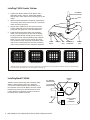
Installing 1500A Counter Stations
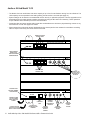
GOOSENECK
MICROPHONE
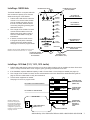
1. Unpack each Model 1500A Counter Station and, if
applicable, install a 1501A or 1502A Video Display.
Plug the Cat 5 video cable into the matching port on the
1500A.
BOOT
2. Attach the field-replaceable microphone, tightening the
nut securely with a 18mm flare nut wrench, and tuck its
rubber boot firmly into place.
18MM NUT
3. Plug the Cat 5 cable from the hub into the Hub port
of each 1500A and connect the power supply to the
Power jack. See page 9 for Cat 5 cable fabrication.
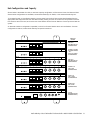
4. Install the desired keyboard inlays into the Model
1500A. On initial power-up, the hub sets the default
key layout automatically according to the number of
connected Counter and Lane Stations (see examples
below). You can choose to color-code by the carrier
color or label the keys numerically. Place blank, black
chips in all non-active positions. Save the unused key
chips on the premises for future changes or expansion.
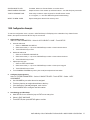
Single Lane (1x1) Default
1509 or 1510 Default
MIC PORT
POWER
SUPPLY
HEADSET
1511 Default
HUB
PORT
VIDEO DISPLAY
CONNECTION
HANDSET
PORT
1512 Default
Illustration: Default key assignmens for various lane configurations. Key assignments may be changed from default by connecting a 1550 Field Setup
Tool and accessing “teller parameters” and “key assignment.” See page. 15.
Installing Model 1500AH
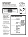
1500AH Counter Stations ship with a handset cradle
attached. Install them the same as a 1500A but
connect the included handset to the handset port on
the underside of the Counter Station as shown. Adjust
handset volume using the 1550 field setup tool, then,
if more adjustment is desired, use the two knobs on
the bottom of the 1500AH as shown.
RX = Inbound
Handset Audio
TX = Outbound
Handset Audio
CRADLE
6
HANDSET
PORT
Audio Authority® Series 1500 Installer’s Reference Guide • Firmware Version 4.0
1500AH COUNTER
STATION
(UNDERSIDE)