1
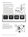
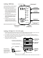
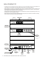
Installing a 1509SD Hub
PROGRAM AUDIO INPUTS
The Model 1509SD is a compact audio hub
with a maximum capacity of two Counter
Stations serving four Lane Stations.
1. Position and install the Hub under the
counter or in a secure indoor location
such as a telephone closet. Ground
the hub to a nearby electrical device
cover using the green grounding wire
attached to the hub.
PROGRAM AUDIO VOLUME
LEVEL ADJUSTMENT
CAT 5 CABLE TO
COUNTER STATION #1
LEVEL
COUNTER
STATION 1
PROGRAM AUDIO
COUNTER
STATION 2
CAT 5 CABLE TO
LANE STATION #1
LANE
STATION 1
LANE
STATION 2
2. Run a length of Cat 5 cable from each
counter and lane station to the hub.
Observe the wiring guide on page 9,
and use a cable tester to verify the
terminations.
LANE
STATION 3
LANE
STATION 4
3. If desired, connect an audio source
to Program Audio jacks, and adjust
volume level during system testing.
See page 9 for more on program audio.
1 AMP POWER SUPPLY
(MODEL 571-013)
12 VOLT
DC POWER
SD CARD
Illustration: Shown is Model 1509SD Audio Intercom Hub.
Minimum connections are shown for a 1 on 1 system.
SD CARD FOR STORING
SYSTEM SETTINGS AND
FIELD UPGRADES
DIAGNOSTICS
GROUND WIRE TO ELECTRICAL
DEVICE COVER
DIAGNOSTICS PORT
(NOT CURRENTLY USED)
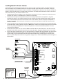
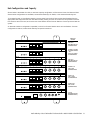
Installing a 1510 Hub (1511, 1512, 1513 similar)
1. Position and install the Hub under the counter or in a secure indoor location such as a telephone closet. Ground the
hub to a nearby electrical device cover using the green grounding wire attached to the hub.
2. If the installation requires additional capacity, install a Counter Card or Lane Card(s) as needed (see page 13).
3. Run a length of Cat 5 cable from each counter and lane station to the hub. Observe the cable fabrication guide on
page 9, and use a cable tester to verify the terminations.
4. Connect other equipment as needed.
See page 9 for more on program audio.
CAT 5 CABLE TO COUNTER STATION #1
FOUR-UNIT COUNTER STATION CARD
(MODEL 1515)
CAT 5 CABLE TO LANE STATION #1
FOUR-UNIT LANE
STATION CARD
(MODEL 1516)
GROUND WIRE
Illustration: Model 1510,
the minimum capacity A/V
Hub configuration. Minimum
connections for Audio/Video
Hubs are shown. For more
configurations, system card
functions, and other connections,
see page 12 and 13.
SYSTEM CARD
(MODEL 1517SD)
SEE PAGE 12
FOR INSTRUCTIONS
1 AMP POWER SUPPLY
(MODEL 571-013)
POWER CONNECTION
Audio Authority® Series 1500 Installer’s Reference Guide • 800-322-8346 • 859-233-4599
7