1
Installing Model 1520 Lane Stations
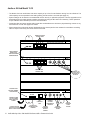
Lane Stations may be placed at the customer end of a drive-up or walk-up intercom system. The Model 1520 is the
basic Lane Station unit for installations where the microphone, speaker (plus video screen and camera, if used) are
mounted separately. The Model 1522 is a Video Lane Station, including all of the features of the 1520 plus microphone,
speaker, camera and video screen mounted inside one enclosure. The Model 1523 Video Add-on must be used with a
1520, and contains only the camera and video screen.
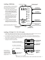
1. Install the Model 1520 Lane Station in each deal drawer or pneumatic unit on the customer end, using the screws
provided. If AC power is not available at the customer end, see Step 5.
2. Install the lane microphones and speakers if they are not already installed. Mount the speakers in the grilles
provided in the drive-up units. Peel the backing from the microphone shrouds and adhere them directly centered
over a 1/8” hole drilled in the faces of the customer units. At each station, place the microphone and speaker as
far apart as practical, while centering the microphone to receive customer speech. Install Teller Call push-button
switches, if needed.
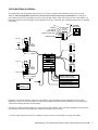
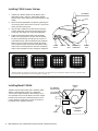
3. Connect the Microphones, Speakers and Teller Call switches to the 1520 terminal blocks. Strip all wires 1/4” long.
If pneumatic blower muting is desired, connect the DRY blower contacts to the corresponding points on the terminal
blocks, using small (22-18 AWG) wire. If traffic sensing devices or remote-controlled security doors are in use,
connect them as indicated.
4. At each lane where video is in use, connect a Model 1523 Video Add-on to the Video port on the 1520 or connect
standard 75-ohm NTSC cameras and monitors to the 1520 video jacks. Plug power supplies into the Power jacks.
5. Plug the lane power supplies into a source of 100-240 volts AC. An adapter cable is provided with the 1520 to allow
power to be drawn from a terminal block in a pneumatic unit. If AC power is not available on the customer end,
a power supply may be located indoors and its output leads extended using a suitable gauge of wire as shown
below. To power multiple lane units from a single power supply source, contact Audio Authority Technical Support at
800‑322‑8346.
MICROPHONE
SPEAKER
CALL BUTTON
3RD PARTY
Traffic
Sensor
POWER
TRAFFIC SENSE
1 +
2 –
MICROPHONE
3 +
4 –
SPEAKER
MONITOR
5 CALL BUTTON
BLOWER
6 TRAFFIC SENSE
7 BLOWER
8 COMMON
9
10
ANY DEVICE TO BE
+
CONTROLLED BY RELAY –
HANDSET
Recommended AWG
Maximum
Distance
40 ft
60 ft
100 ft
8
Gauge
18
16
14
1547 cable
may be
extended
using Cat 5
Model 1547
Traffic
Sensor
Audio Authority® Series 1500 Installer’s Reference Guide • Firmware Version 4.0
CAMERA
N.O. CONTACTS
1523
VIDEO
MODULE
HUB
CABLE ADJUST
(SEE INSTRUCTIONS)
1547 connects to port
behind knock out.