1
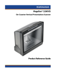
PowerScan® 7000BT SRI
Linear Imager
Product Reference Guide
Datalogic Scanning, Inc.
959 Terry Street
Eugene, Oregon 97402
Telephone: (541) 683-5700
Fax: (541) 345-7140
An Unpublished Work - All rights reserved. No part of the contents of this documentation or the procedures
described therein may be reproduced or transmitted in any form or by any means without prior written permission of Datalogic Scanning, Inc. or its subsidiaries or affiliates ("Datalogic" or “Datalogic Scanning”).
Owners of Datalogic products are hereby granted a non-exclusive, revocable license to reproduce and
transmit this documentation for the purchaser's own internal business purposes. Purchaser shall not
remove or alter any proprietary notices, including copyright notices, contained in this documentation and
shall ensure that all notices appear on any reproductions of the documentation.
Should future revisions of this manual be published, you can acquire printed versions by contacting your
Datalogic representative. Electronic versions may either be downloadable from the Datalogic website
(www.scanning.datalogic.com) or provided on appropriate media. If you visit our website and would like to
make comments or suggestions about this or other Datalogic publications, please let us know via the "Contact Datalogic" page.
Disclaimer
Datalogic has taken reasonable measures to provide information in this manual that is complete and accurate, however, Datalogic reserves the right to change any specification at any time without prior notice.
Datalogic is a registered trademark of Datalogic S.p.A. and the Datalogic logo is a trademark of Datalogic
S.p.A. all licensed to Datalogic Scanning, Inc. All other trademarks and trade names referred to herein are
property of their respective owners.
Patents
This product may be covered by one or more of the following patents: 4603262 • 4639606 • 4652750 • 4672215 • 4699447
• 4709369 • 4749879 • 4786798 • 4792666 • 4794240 • 4798943 • 4799164 • 4820911 • 4845349 • 4861972 • 4861973 •
4866257 • 4868836 • 4879456 • 4939355 • 4939356 • 4943127 • 4963719 • 4971176 • 4971177 • 4991692 • 5001406 •
5015831 • 5019697 • 5019698 • 5086879 • 5115120 • 5144118 • 5146463 • 5179270 • 5198649 • 5200597 • 5202784 •
5208449 • 5210397 • 5212371 • 5212372 • 5214270 • 5229590 • 5231293 • 5232185 • 5233169 • 5235168 • 5237161 •
5237162 • 5239165 • 5247161 • 5256864 • 5258604 • 5258699 • 5260554 • 5274219 • 5296689 • 5298728 • 5311000 •
5327451 • 5329103 • 5330370 • 5347113 • 5347121 • 5371361 • 5382783 • 5386105 • 5389917 • 5410108 • 5420410 •
5422472 • 5426507 • 5438187 • 5440110 • 5440111 • 5446271 • 5446749 • 5448050 • 5463211 • 5475206 • 5475207 •
5479011 • 5481098 • 5491328 • 5493108 • 5504350 • 5508505 • 5512740 • 5541397 • 5552593 • 5557095 • 5563402 •
5565668 • 5576531 • 5581707 • 5594231 • 5594441 • 5598070 • 5602376 • 5608201 • 5608399 • 5612529 • 5629510 •
5635699 • 5641958 • 5646391 • 5661435 • 5664231 • 5666045 • 5671374 • 5675138 • 5682028 • 5686716 • 5696370 •
5703347 • 5705802 • 5714750 • 5717194 • 5723852 • 5750976 • 5767502 • 5770847 • 5786581 • 5786585 • 5787103 •
5789732 • 5796222 • 5804809 • 5814803 • 5814804 • 5821721 • 5822343 • 5825009 • 5834708 • 5834750 • 5837983 •
5837988 • 5852286 • 5864129 • 5869827 • 5874722 • 5883370 • 5905249 • 5907147 • 5923023 • 5925868 • 5929421 •
5945670 • 5959284 • 5962838 • 5979769 • 6000619 • 6006991 • 6012639 • 6016135 • 6024284 • 6041374 • 6042012 •
6045044 • 6047889 • 6047894 • 6056198 • 6065676 • 6069696 • 6073849 • 6073851 • 6094288 • 6112993 • 6129279 •
6129282 • 6134039 • 6142376 • 6152368 • 6152372 • 6155488 • 6166375 • 6169614 • 6173894 • 6176429 • 6188500 •
6189784 • 6213397 • 6223986 • 6230975 • 6230976 • 6237852 • 6244510 • 6259545 • 6260763 • 6266175 • 6273336 •
6276605 • 6279829 • 6290134 • 6290135 • 6293467 • 6303927 • 6311895 • 6318634 • 6328216 • 6332576 • 6332577 •
6343741 • 6454168 • 6478224 • 6568598 • 6578765 • 6705527 • 6974084 • 6991169 •7051940 • AU703547 • D312631 •
D313590 • D320011 • D320012 • D323492 • D330707 • D330708 • D349109 • D350127 • D350735 • D351149 • D351150
• D352936 • D352937 • D352938 • D352939 • D358588 • D361565 • D372234 • D374630 • D374869 • D375493 •
D376357 • D377345 • D377346 • D377347 • D377348 • D388075 • D446524 • EP0256296 • EP0260155 • EP0260156 •
EP0295936 • EP0325469 • EP0349770 • EP0368254 • EP0442215 • EP0498366 • EP0531645 • EP0663643 •
EP0698251 • GB2252333 • GB2284086 • GB2301691 • GB2304954 • GB2307093 • GB2308267 • GB2308678 •
GB2319103 • GB2333163 • GB2343079 • GB2344486 • GB2345568 • GB2354340 • ISR107546 • ISR118507 •
ISR118508 • JP1962823 • JP1971216 • JP2513442 • JP2732459 • JP2829331 • JP2953593 • JP2964278 • MEX185552 •
MEX187245 • RE37166 • Other Patents Pending
Table of Contents
About This Manual ............................................................................ 1-2
Manual Conventions .................................................................... 1-2
Connection ................................................................................ 1-2
Linking the Scanner to a Base Station ................................................. 1-4
Optional: Linking the Scanner to a PC .................................................. 1-6
Paging Feature ................................................................................. 1-6
Programming ................................................................................... 1-7
Resetting the Standard Product Defaults .............................................. 1-7
Double Read Timeout ........................................................................ 2-1
Powerdown Timeout .......................................................................... 2-3
LED and Beeper Indicators ................................................................. 2-5
Power On Alert ........................................................................... 2-5
LED Idle State ............................................................................ 2-6
Good Read: When to Indicate ....................................................... 2-7
Good Read Beep Control .............................................................. 2-8
Good Read Beep Frequency ......................................................... 2-9
Good Read Beep Length ............................................................ 2-10
Good Read Beep Volume ........................................................... 2-12
Scanning Features .......................................................................... 2-13
Scan Mode .............................................................................. 2-13
Active Scanning Time ................................................................ 2-15
Laser Pointer Control ................................................................ 2-16
Interface Selection ............................................................................ 3-4
Interface Features ............................................................................ 3-9
Global Interface Features ............................................................ 3-9
RS-232 Interface Features ......................................................... 3-10
Hardware Flow Control......................................................... 3-14
Intercharacter Delay............................................................ 3-14
Software Flow Control.......................................................... 3-14
Host Echo .......................................................................... 3-18
Host Echo Quiet Interval ...................................................... 3-18
Signal Voltage: Normal/TTL .................................................. 3-18
RS-232 Invert..................................................................... 3-18
Beep on ASCII BEL .............................................................. 3-21
Beep on Not on File ............................................................. 3-21
ACK NAK Options ................................................................ 3-22
ACK Character .................................................................... 3-24
NAK Character .................................................................... 3-25
Retry on ACK NAK Timeout................................................... 3-26
ACK NAK Timeout Value ....................................................... 3-27
ACK NAK Retry Count .......................................................... 3-28
ACK NAK Error Handling ............................................................ 3-29
Transmission Failure Indication ............................................. 3-30
IBM-USB Interface Features ....................................................... 3-31
IBM-USB Device usage......................................................... 3-31
IBM ........................................................................................ 3-32
Product Reference Guide
i
IBM Transmit Labels in Code 39 Format .................................. 3-32
Wand Emulation ....................................................................... 3-33
Supported Symbologies ........................................................ 3-33
Wand Emulation Bar Code Format .......................................... 3-33
Bar/Space Polarity ............................................................... 3-34
Wand Idle State .................................................................. 3-34
Signal Speed ....................................................................... 3-36
Transmit Trailing Noise ......................................................... 3-37
Transmit Leading Noise ........................................................ 3-38
Symbology Conversion ......................................................... 3-39
Keyboard Wedge/USB Keyboard .................................................. 3-40
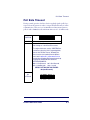
Data Editing Overview .......................................................................4-1
Please Keep In Mind... .................................................................4-2
Global Prefix/Suffix ............................................................................4-2
AIM ID .............................................................................................4-5
Label ID ...........................................................................................4-7
Case Conversion ....................................................................... 4-15
Character Conversion ................................................................ 4-16
Auto Configuration Update ..................................................................5-2
Auto Flash Memory Update .................................................................5-3
Non-Automatic Updates .....................................................................5-4
Flash Update to Scanner ..............................................................5-4
Copy Configuration to Scanner ......................................................5-4
Copy Configuration to Base Station ...............................................5-4
Do Not Send Configuration to Scanner ...........................................5-5
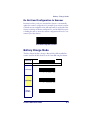
Battery Charge Mode .........................................................................5-5
ACK Timeout ....................................................................................5-6
Poll Rate Timeout ..............................................................................5-7
Transmit HACK .................................................................................5-8
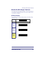
Bluetooth (BT) Beeper Features ..........................................................5-9
BT Beep Volume .........................................................................5-9
BT Beep Duration ...................................................................... 5-10
BT Beep Frequency ................................................................... 5-11
BT Disconnect Beep ................................................................... 5-12
BT ACK Label Beep .................................................................... 5-13
BT Transmission Error Beep ........................................................ 5-14
BT In Cradle Chirp ..................................................................... 5-15
BT Leash Beep .......................................................................... 5-16
UPC-A ..............................................................................................6-2
Disable/Enable UPC-A ..................................................................6-2
Check Digit Transmission .............................................................6-2
Expand UPC-A to EAN-13 .............................................................6-2
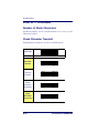
System Number Transmission .......................................................6-2
UPC-A Minimum Reads ................................................................6-5
In-store Minimum Reads ..............................................................6-6
Add-On Timer .............................................................................6-7
UPC-E ..............................................................................................6-8
Disable/Enable UPC-E ..................................................................6-8
Check Digit Transmission .............................................................6-8
System Number ..........................................................................6-8
Expand UPC-E to UPC-A ...............................................................6-8
Expand UPC-E to EAN13 ..............................................................6-8
ii
PowerScan® 7000BT SRI
Minimum Reads ........................................................................ 6-11
GTIN ...................................................................................... 6-12
Disable/Enable GTIN ................................................................. 6-12
EAN-13 ......................................................................................... 6-13
Disable/Enable EAN-13 .............................................................. 6-13
Check Digit Transmission ........................................................... 6-13
EAN-13 Flag 1 Character ........................................................... 6-13
ISBN ...................................................................................... 6-13
Minimum Reads ........................................................................ 6-16
EAN-8 ........................................................................................... 6-17
Disable/Enable EAN-8 ............................................................... 6-17
Check Digit Transmission ........................................................... 6-17
Minimum Reads ........................................................................ 6-19
Add-ons ........................................................................................ 6-20
RSS-14 ......................................................................................... 6-22
Disable/Enable RSS-14 .............................................................. 6-22
UCC/EAN 128 Emulation ............................................................ 6-22
Minimum Reads ........................................................................ 6-24
RSS-14 2D Component ............................................................. 6-25
RSS Expanded ............................................................................... 6-26
Disable/Enable RSS Expanded .................................................... 6-26
UCC/EAN 128 Emulation ............................................................ 6-26
Length Control ......................................................................... 6-27
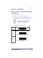
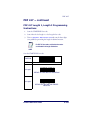
RSS Expanded Length 1, Length 2 Programming Instructions ......... 6-29
Minimum Reads ........................................................................ 6-30
RSS Expanded 2D Component .................................................... 6-31
RSS Limited ................................................................................... 6-32
Disable/Enable RSS Limited ....................................................... 6-32
UCC/EAN 128 Emulation ............................................................ 6-32
Minimum Reads ........................................................................ 6-33
RSS Limited 2D Component ....................................................... 6-34
Code 39 ........................................................................................ 6-35
Disable/Enable Code 39 ............................................................. 6-35
Check Character Calculation ....................................................... 6-35
Check Character Transmit .......................................................... 6-35
Start/Stop Characters ............................................................... 6-35
Code 39 Full ASCII ................................................................... 6-35
Length Control ......................................................................... 6-38
Code 39 Length 1, Length 2 Programming Instructions .................. 6-40
Quiet Zones........................................................................ 6-41
Code 39 Stitching ..................................................................... 6-42
Minimum Reads ........................................................................ 6-43
Pharmacode 39 .............................................................................. 6-44
Disable/Enable Pharmacode 39 ................................................... 6-44
Start/Stop Characters ............................................................... 6-45
Check Character Transmit .......................................................... 6-45
Code 128 and EAN 128 .................................................................... 6-46
Transmit Function Characters ..................................................... 6-47
Length Control ......................................................................... 6-48
Code 128 Length 1, Length 2 Programming Instructions ................ 6-50
Code 128 Stitching ................................................................... 6-51
Minimum Reads ........................................................................ 6-52
Product Reference Guide
iii
Interleaved 2 of 5 ........................................................................... 6-53
Disable/Enable Interleaved 2 of 5 ................................................ 6-53
Check Digit Calculation .............................................................. 6-53
Check Digit Transmit ................................................................. 6-53
Length Control .......................................................................... 6-55
Interleaved 2 of 5 Length 1, Length 2 Programming Instructions ..... 6-57
Interleaved 2 of 5 Stitching ........................................................ 6-58
Minimum Reads ........................................................................ 6-59
Codabar ......................................................................................... 6-60
Disable/Enable Codabar ............................................................. 6-60
Check Character Verification ....................................................... 6-60
Check Character Transmit .......................................................... 6-60
Length Control .......................................................................... 6-62
Codabar Length 1, Length 2 Programming Instructions .................. 6-64
Quiet Zones ........................................................................ 6-65
Start/Stop Character Type .......................................................... 6-66
Start/Stop Character Transmission .............................................. 6-66
Start/Stop Character Match ........................................................ 6-66
Codabar Stitching ..................................................................... 6-69
Minimum Reads ........................................................................ 6-70
Code 93 ......................................................................................... 6-71
Disable/Enable Code 93 ............................................................. 6-71
Length Control .......................................................................... 6-72
Code 93 Length 1, Length 2 Programming Instructions .................. 6-74
Code 93 Stitching ...................................................................... 6-75
Minimum Reads ........................................................................ 6-76
Code 11 ......................................................................................... 6-77
Disable/Enable Code 11 ............................................................. 6-77
Number of Check Characters ...................................................... 6-78
Check Character Transmit .......................................................... 6-78
Length Control .......................................................................... 6-79
Code 11 Length 1, Length 2 Programming Instructions .................. 6-81
Minimum Reads ........................................................................ 6-82
MSI/Plessey ................................................................................... 6-83
Disable/Enable MSI/Plessey ........................................................ 6-83
Check Digit Verification .............................................................. 6-83
Check Digit Transmit ................................................................. 6-83
Length Control .......................................................................... 6-86
MSI/Plessey Length 1, Length 2 Programming Instructions ............. 6-88
MSI/Plessey Stitching ................................................................ 6-89
Minimum Reads ........................................................................ 6-90
Standard 2 of 5 ............................................................................... 6-91
Disable/Enable Standard 2 of 5 ................................................... 6-91
Check Digit Verification .............................................................. 6-91
Check Digit Transmit ................................................................. 6-91
Length Control .......................................................................... 6-93
Standard 2 of 5 Length 1, Length 2 Programming Instructions ........ 6-95
Standard 2 of 5 Stitching ........................................................... 6-96
Minimum Reads ........................................................................ 6-97
PDF 417 ......................................................................................... 6-98
Disable/Enable PDF 417 ............................................................. 6-98
Length Control .......................................................................... 6-99
iv
PowerScan® 7000BT SRI
PDF 417 Length 1, Length 2 Programming Instructions .................6-101
Minimum Reads .......................................................................6-102
Micro PDF 417 ...............................................................................6-103
Disable/Enable Micro PDF 417 ...................................................6-103
PDF 128 Emulation ..................................................................6-104
Length Control ........................................................................6-105
Micro PDF 417 Length 1, Length 2 Programming Instructions ........6-107
Minimum Reads .......................................................................6-108
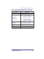
Optical and Read Performance Parameters ........................................... A-1
Physical Properties: Scanner .............................................................. A-2
Physical Properties: Base Station ........................................................ A-2
Electrical Parameters: Base Station ..................................................... A-2
Environmental Parameters: Scanner ................................................... A-3
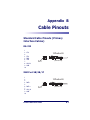
Standard Cable Pinouts (Primary Interface Cables) ................................ B-1
RS-232 ..................................................................................... B-1
IBM Port 5B/9B/17 ..................................................................... B-1
IBM USB ................................................................................... B-2
USB & USB Keyboard .................................................................. B-2
Wand Emulation ......................................................................... B-2
Keyboard Wedge ........................................................................ B-3
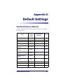
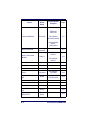
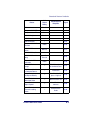
Standard Feature Defaults .................................................................D-1
Keyboard Model Cross Reference ........................................................ E-1
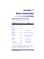
Accepting RS-232 Commands ............................................................. F-1
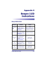
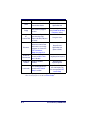
Beep Indications ............................................................................... H-1
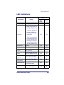
LED Indications ................................................................................ H-3
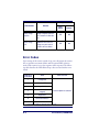
Error Codes ..................................................................................... H-4
Product Reference Guide
v
vi
PowerScan® 7000BT SRI
Chapter 1
Getting Started
The PowerScan® 7000BT SRI Linear Imager uses Bluetooth® wireless
technology1 for communications between the handheld scanner and
Base Station (or PC). The scanner and Base station operate on a master/
slave system, with the Base station acting as the master and the scanner as
the slave.
The handheld itself marks a new performance level in bar code scanning.
It delivers aggressive read rates and depths of field on 1D and stacked
codes. This aggressiveness applies even in challenging reading environments where low lighting conditions and poor quality might make it difficult to read bar codes. You can rest assured your investment will
continue to supply years of use by reading any bar codes you require,
now or in the future.
Designed for today’s demanding commercial and industrial environments, the scanner offers superior image quality, speed, durability, and
the ability to read poor quality bar codes. The unit is comfortable to
hold, easy to use, rugged, and excellent for the most demanding applications.
1. The Bluetooth® word mark and logos are owned by the Bluetooth SIG, Inc.
Product Reference Guide
1-1
Getting Started
About This Manual
This Product Reference Guide (PRG) provides programming instructions for the scanner, plus product specifications and dimensions. For
installation, maintenance, troubleshooting and warranty information,
see the Quick Reference Guide (QRG). Copies of other publications for
this product are downloadable free of charge from the website listed on
the back cover of this manual.
The scanner is factory programmed for the most common terminal and
communications settings. If you need to change these settings, programming is accomplished by scanning the bar codes in this guide.
Bold text and a yellow-highlighted background indicates the most common default setting for a feature/option.
Manual Conventions
The symbols listed below are used in this manual to notify the reader of
key issues or procedures that must be observed when using the scanner:
Notes contain information necessary for properly diagnosing, repairing and operating the
scanner.
NOTE
The CAUTION symbol advises you of actions
that could damage equipment or property.
CAUTION
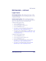
Connection
shows how to connect the Base Station to a terminal, PC or
other host device. Turn off the host before connection and consult the
manual for that equipment (if necessary) before proceeding.
Figure 1-1
1-2
PowerScan® 7000BT SRI
About This Manual
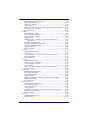
Base Station Connection and Routing — Fully insert the Power Cable and
Interface (I/F) Cable connectors into their respective ports in the underside of the Base Station (see Figure 1-1). Alternatively, you can either loop
the cables around the routing clips and back through the routing channel to the front of the Base Station as shown, or the cables can be fed
directly out the back of the Base Station via the routing clips.
Figure 1-1. Connecting the Base Station
Power Cable
I/F
Cable
Routing
Channel
Routing
Clips
Bottom of Base Station
I/F Cable
AC
Adapter
Base
Station
Power Cable
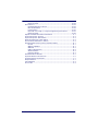
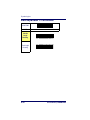
Host Connection — The interface type was specified at the time your scanner was ordered, however you should verify before connection that the
scanner’s cable type is compatible with your host equipment. Most connections plug directly into the host device as shown in Figure 1-2. Keyboard Wedge interface cables have a ‘Y’ connection where its female end
mates with the male end of the cable from the keyboard and the remaining end at the keyboard port on the terminal/PC.
Product Reference Guide
1-3
Getting Started
B
Figure 1-2. Connecting to the Host
or...
nd
Wa
b
ed oar
ge d
or...
M
or...
K ey
W
US
IB
Power Connection — Plug the AC Adapter in to an approved AC wall
socket with the cable facing downwards (as shown in Figure 1-1) to prevent undue strain on the socket.
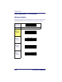
Linking the Scanner to a Base Station
To link a scanner to a Base Station, press the Link Button (see Figure 1-3)
on the Base Station for at least one second to place the base in "Link
Mode," then scan the bar code below or the Link bar code located on the
Base Station using the scanner to be linked. The Link bar code on the
Base Station contains an identifier that is unique to that Base Station.
This enables the scanner to quickly find and link to that Base Station.
1-4
PowerScan® 7000BT SRI
Linking the Scanner to a Base Station
Linking the Scanner to a Base Station —
cont.
When the generic Link to Base Station label (shown below) is used for
linking, you will notice that linking is slower and a rescan of the label
may be required before a successful link is made. If two Base Stations are
in the linking mode at the same time, the generic label will not be able to
initiate a successful link, since the scanner will not know which Base Station it is supposed to link to.
A successful link is indicated by three ascending tones from the scanner.
A high-low-high-low tone indicates the link attempt was unsuccessful. A
single green LED flash during this tone indicates no Base Station was
discovered. Two green LED flashes during this tone indicates that more
than one Base Station was discovered and the scanner did not link.
Link to Base Station
Figure 1-3. Labeling and Nomenclature
This illustration shows label placement ONLY.
For actual regulatory, patent and other applicable
information, view the labels on the product intself,
or call your nearest sales or service office.
Antenna
Link Bar Code
Scanner
Scan
Window
Link
Button
Trigger
Green LED
Amber
LED
S/N and Laser Safety Label
Indicator
LEDs
Speaker
Port
Battery Pack
Battery Latch
Product Reference Guide
Scanner
Latch
Base Station
1-5
Getting Started
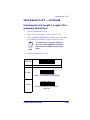
Optional: Linking the Scanner to a PC
A scanner can optionally be linked to a Bluetooth-enabled PC with the
serial port profile. To do this, follow these steps:
1. Ensure the PC or terminal can network with Bluetooth devices
and that it is powered on.
2. Scan the “Link to a PC” bar code below.
Link to a PC
3. On the PC, scan for network devices.
4. Select the “Datalogic PS7000 Scanner1.” Make sure “Secure Connection” is disabled.
5. Select “connect” on the PC to link the scanner to the PC.
Paging Feature
To help locate a missing scanner, press the Base Station Link Button
momentarily (less than one second). This will cause the scanner to beep
five times at its loudest volume setting.
1. Depending upon when your scanner was purchased, your selection may be 'PSC PS7000
Scanner.”
1-6
PowerScan® 7000BT SRI
Programming
Programming
This manual contains feature descriptions and bar codes which allow
you to reconfigure your scanner. Some programming bar code labels, like
the label below for resetting defaults, require only the scan of that single
label to enact the change. Most of the programming labels in this manual, however, require the scanner to be placed in Programming Mode
prior to scanning them. Unless instructed otherwise for feature configuration, scan a START/END bar code once to enterProgramming Mode.
Once the scanner is in Programming Mode, you can scan a number of
parameter settings before scanning the START/END bar code a second
time, which will then accept your changes, exit Programming Mode and
return the scanner to normal operation.
The scanner is typically factory-configured with a set of default features
standard to the interface type you ordered. After scanning the interface
bar code from the Interface Related Features section, you can select other
options and customize your scanner through use of the instructions and
programming bar codes available in that section and also the Data Editing
and Symbologies chapters of this manual.
Resetting the Standard Product
Defaults
If you aren’t sure what programming options are in your scanner, or
you’ve changed some options and want the factory settings restored, scan
the Standard Product Default Settings bar code below. This will copy the
factory configuration for the currently active interface to the current
configuration.
Standard Product Default Settings
The programming section lists the factory default settings for each of the
menu commands (indicated by shaded blocks and bold text) on the following pages.
Product Reference Guide
1-7
Getting Started
NOTES
1-8
PowerScan® 7000BT SRI
Chapter 2
General Features
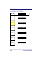
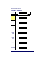
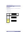
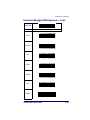
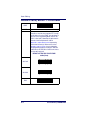
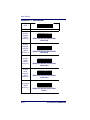
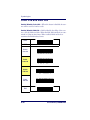
Double Read Timeout
The Double Read Timeout feature sets a time limit that determines how much time
must pass before reading the same label again (e.g. two identical items in succession).
START/END
DURATION
BAR CODE
0.1 Second
0.2 Second
0.3 Second
0.4 Second
Product Reference Guide
2-1
General Features
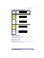
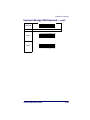
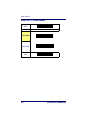
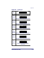
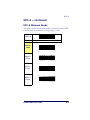
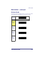
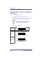
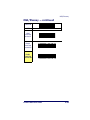
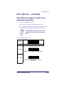
Double Read Timeout — continued
START/END
DURATION
BAR CODE
0.5 Second
0.6 Second
0.7 Second
0.8 Second
0.9 Second
1 Second
2-2
PowerScan® 7000BT SRI
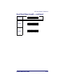
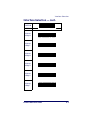
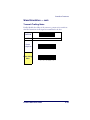
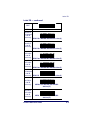
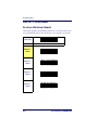
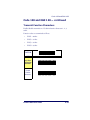
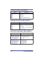
Powerdown Timeout
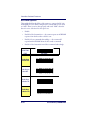
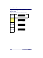
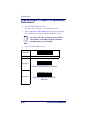
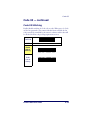
Powerdown Timeout
The Powerdown Timeout feature sets the time for automatically switching the scanner
off when it is not in use.
START/END
DURATION
BAR CODE
Disable
15 Seconds
30 Seconds
5 Minutes
Product Reference Guide
2-3
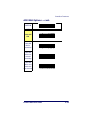
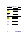
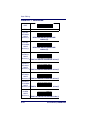
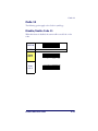
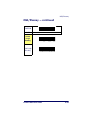
General Features
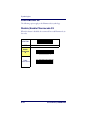
START/END
DURATION
BAR CODE
15 Minutes
30 Minutes
1 Hour
2-4
PowerScan® 7000BT SRI
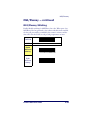
LED and Beeper Indicators
LED and Beeper Indicators
The features provided in this section concern general system LED and
Beeper indications. For indication features specific to radio frequency,
see the Bluetooth Features section of this manual.
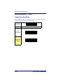
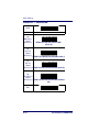
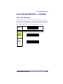
Power On Alert
Disables or enables the indication (from the Beeper) that the scanner is
receiving power.
START/END
STATE
BAR CODE
Disable
Enable
Product Reference Guide
2-5
General Features
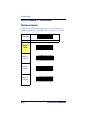
LED Idle State
Specifies state of scanner’s LED when the scanner is ready to read a bar
code.
START
STATE
BAR CODE
Disable
Enable
END
2-6
PowerScan® 7000BT SRI
LED and Beeper Indicators
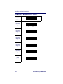
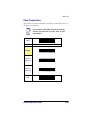
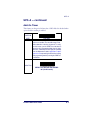
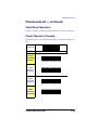
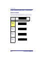
Good Read: When to Indicate
This feature specifies when the scanner will provide indication (beep
and/or flash its green LED) upon successfully reading a bar code.
Choices are:
•
Good Read = Indicate after decode
•
Good Read = Indicate after transmit
•
Good Read = Indicate after CTS goes inactive, then active
This option, which uses CTS, is only valid for RS-232
interfaces.
NOTE
START/END
INDICATE
BAR CODE
After decode
After transmit
After CTS goes
inactive, then
active
Product Reference Guide
2-7
General Features
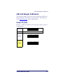
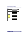
Good Read Beep Control
This feature enables/disables the scanner’s ability to beep upon a successful decode of a bar code.
START/END
STATE
BAR CODE
Disable
Enable
2-8
PowerScan® 7000BT SRI
LED and Beeper Indicators
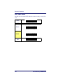
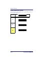
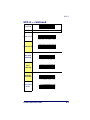
Good Read Beep Frequency
Adjusts the good read beep to sound at a selectable low, medium or high
frequency, selectable from the list below. (Controls the beeper’s pitch/
tone.)
START/END
FREQUENCY
BAR CODE
Low
Medium
High
Product Reference Guide
2-9
General Features
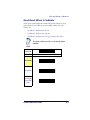
Good Read Beep Length
Specifies the duration of a good read beep.
START/END
LENGTH
BAR CODE
60msec
80msec
100msec
120msec
140msec
160msec
2-10
PowerScan® 7000BT SRI
LED and Beeper Indicators
Good Read Beep Length — continued
START/END
LENGTH
BAR CODE
180msec
200msec
Product Reference Guide
2-11
General Features
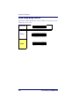
Good Read Beep Volume
Selects the beeper volume (loudness) upon a good read beep. There are
three selectable volume levels.
START/END
VOLUME
BAR CODE
Low
Medium
High
2-12
PowerScan® 7000BT SRI
Scanning Features
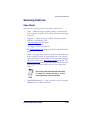
Scanning Features
Scan Mode
Selects the scan operating mode for the scanner. Selections are:
•
Single — When the trigger is pulled, scanning is activated until
five seconds have elapsed or a bar code has been read or the trigger
is released
•
Triggerless — When the trigger is pulled, scanning is activated
until any of the following occur:
- Active Scanning Time has expired
- a bar code has been read
- the trigger is pulled a second time
The Double Read Timeout feature gates double reads while in this
mode.
•
Stand — No trigger pull is required to read a bar code while in this
mode. Scanning is turned on automatically (auto-sense) when an
item is placed in the scanner's field of view and is turned off again
when a bar code is read or Active Scanning Time has expired. The
Double Read Timeout feature gates double reads while in this mode.
If the trigger is pulled, the scanner acts as if it is in single read
mode.
Upon exiting Single Read mode while Stand Mode
is enabled, the software will delay 2 seconds
before beginning its auto-sense operation.
NOTE
•
Stand With Illumination — Same as the option above, except that
illumination is on while in this mode.
Product Reference Guide
2-13
General Features
Scan Mode — continued
START/END
MODE
BAR CODE
Single
Triggerless
Stand
Stand w/Illum
2-14
PowerScan® 7000BT SRI
Scanning Features
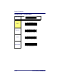
Active Scanning Time
This setting determines the amount of time the scanner continues to
scan in triggerless or stand mode (see Scan Mode) once scanning has been
activated.
START/END
DURATION
BAR CODE
1 Second
2 Seconds
5 Seconds
15 Seconds
30 Seconds
1 Minute
Product Reference Guide
2-15
General Features
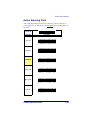
Active Scanning Time — continued
START/END
DURATION
BAR CODE
2 Minutes
3 Minutes
4 Minutes
Laser Pointer Control
The Laser Pointer is a value-added option which
might not have been included when your scanner was ordered.
NOTE
When the trigger is pressed and Scan Mode is set to Single, the laser
pointer will be activated for the time period configured by this feature.
Immediately following this, the scanner will start scanning. Disabling
this feature turns the pointer off.
2-16
PowerScan® 7000BT SRI
Scanning Features
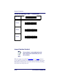
Laser Pointer Control — continued
START/END
DURATION
BAR CODE
Disable
0.1 Seconds
0.2 Seconds
0.3 Seconds
0.4 Seconds
0.5 Seconds
Product Reference Guide
2-17
General Features
Laser Pointer Control — continued
START/END
DURATION
BAR CODE
0.6 Seconds
0.8 Seconds
1 Second
1.2 Seconds
1.5 Seconds
2 Seconds
2.5 Seconds
2-18
PowerScan® 7000BT SRI
Chapter 3
Interface Related
Features
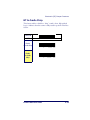
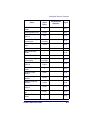
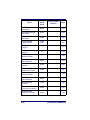
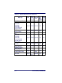
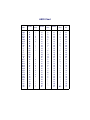
At the time of this writing, the Scanner supports the interfaces listed in
Table 3-1. Select the desired interface type from the table, then reference
the page number given for the customizable features section associated
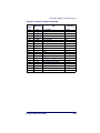
with each interface. See Table 3-2 for a description of each Keyboard
Wedge interface type (A through Z as listed).
Product Reference Guide
3-1
Interface Related Features
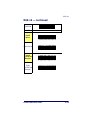
Table 3-1. Interfaces Supported
RS-232
Page Keyboard Wedge
Page
RS-232 Standard
3-10
Keyboard Wedge Ha
RS-232 Wincor-Nixdorf
3-10
Keyboard Wedge Ia
3-40
Keyboard Wedge Ja
3-40
IBM
IBM 4683 Port 5B
3-31
Keyboard Wedge Ka
3-40
IBM 4683 Port 9B
3-31
Keyboard Wedge La
3-40
IBM 4683 Port 17
3-31
Keyboard Wedge Ma
3-40
Keyboard Wedge Na
3-40
USB
IBM USB
3-31
Keyboard Wedge Oa
3-40
USB Keyboard
3-31
Keyboard Wedge Pa
3-40
Wand Emulation
3-33
Keyboard Wedge Qa
3-40
Keyboard Wedge
3-40
Keyboard Wedge Ra
3-40
Aa
3-40
a
Keyboard Wedge S
3-40
Keyboard Wedge Ba
3-40
Keyboard Wedge Ta
3-40
Keyboard Wedge Ca
3-40
Keyboard Wedge Ua
3-40
Keyboard Wedge Da
3-40
Keyboard Wedge Va
3-40
Keyboard Wedge Ea
3-40
Keyboard Wedge Wa
3-40
Keyboard Wedge Fa
3-40
Keyboard Wedge Xa
3-40
Keyboard Wedge Ga
3-40
Keyboard Wedge Ya
3-40
Keyboard Wedge
a. Consult Table 3-2 for more information regarding keyboard wedge interface types.
The correct interface cable is included for the scanner
interface type you ordered.
NOTE
3-2
PowerScan® 7000BT SRI
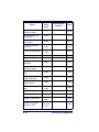
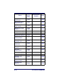
Table 3-2. Keyboard Wedge Interface Reference
I/F Type
PCs Supported
A
PC/XT w/Alternate Key Encoding
AT, PS/2 25-286, 30-286, 50, 50Z, 60, 70, 80, 90 & 95 w/Alternate Key
B
Encoding
C
PS/2 25 and 30 w/Alternate Key Encoding
D
PC/XT w/Standard Key Encoding
AT, PS/2 25-286, 30-286, 50, 50Z, 60, 70, 80, 90 & 95 w/Standard Key
E
Encoding
F
PS/2 25 and 30 w/Standard Key Encoding
G
IBM 3xxx w/122 keyboard
H
IBM 3xxx w/102 keyboard
I
PS/55 5530T w/104 keyboard
J
NEC 9801
K
WYSE 30/30+ WY-30 Keyboard 83 Keys
WYSE 60/85/99 GT/150/160/285 Style IBM Enhanced PC, 520/520ES
L
Style IBM Enhanced PC FR
WYSE 55/65/65 ES/120/185/325 Style IBM Enhanced PC
WYSE 60/85/99 GT/150/160/285 ANSI Keyboard 105 Keys, 520/520 ES
M
ANSI Keyboard 105 Keys
WYSE 55/65/65 ES/120/185/325 ANSI Keyboard 105 Keys
WYSE 60/85/99 GT/150/160/285 ASCII Kbd, 520/520 ES ASCII Kbd
N
WYSE 55/65/65 ES/120/185/325 ASCII Keyboard
WYSE 60/85/99 GT/150/160/285 ANSI W285 Keyboard 105 Keys, 520/
O
520 ES ANSI W285 Keyboard 105 Keys
WYSE 55/65/65 ES/120/185/325 ANSI W285 Keyboard 105 Keys
P
WYSE WINTERM 3320 SE
IBM 3153
Q
IBM 316X, 3179/3180/319X/3270
R
IBM 3151/3152-010, 347X/348X
S
DIGITAL VT 220/320/330/340/350/382
T
DIGITAL VT420
U
DIGITAL VT 510/520 IBM ANSI Style Keyboard
V
DIGITAL VT 510/520 IBM PC Style Keyboard
W
SUN SPARC 5/10
X
SUN 420/440, ITX
Y
WYSE 370/355 Style Enhanced IBM PC
Reference Appendix E, Keyboard Function Key Mappings for more information about keyboards.
NOTE
Product Reference Guide
3-3
Interface Related Features
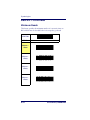
Interface Selection
START/END
INTERFACE
BAR CODE
RS-232
Standard
RS-232
Wincor-Nixdorf
IBM 4683
Port 5B
IBM 4683
Port 9B
IBM 4683
Port 17
IBM USB
USB Keyboard
3-4
PowerScan® 7000BT SRI
Interface Selection
Interface Selection — cont.
START/END
INTERFACE
BAR CODE
Keyboard
Wedge A
Keyboard
Wedge B
Keyboard
Wedge C
Keyboard
Wedge D
Keyboard
Wedge E
Keyboard
Wedge F
Keyboard
Wedge G
Product Reference Guide
3-5
Interface Related Features
Interface Selection — cont.
START/END
INTERFACE
BAR CODE
Keyboard
Wedge H
Keyboard
Wedge I
Keyboard
Wedge J
Keyboard
Wedge K
Keyboard
Wedge L
Keyboard
Wedge M
Keyboard
Wedge N
3-6
PowerScan® 7000BT SRI
Interface Selection
Interface Selection — cont.
START/END
INTERFACE
BAR CODE
Keyboard
Wedge O
Keyboard
Wedge P
Keyboard
Wedge Q
Keyboard
Wedge R
Keyboard
Wedge S
Keyboard
Wedge T
Product Reference Guide
3-7
Interface Related Features
Interface Selection — cont.
START/END
INTERFACE
BAR CODE
Keyboard
Wedge U
Keyboard
Wedge V
Keyboard
Wedge W
Keyboard
Wedge X
Keyboard
Wedge Y
Wand
Emulation
3-8
PowerScan® 7000BT SRI
Interface Features
Interface Features
Global Interface Features
START/END
STATE
BAR CODE
Obey Host
Commands
Ignore Host
Commands
Host
Transmission
Buffers = 1
Host
Transmission
Buffers = 2
Product Reference Guide
3-9
Interface Related Features
RS-232 Interface Features
START/END
BAUD RATE
BAR CODE
1200 Baud
2400 Baud
4800 Baud
9600 Baud
19200 Baud
38400 Baud
3-10
PowerScan® 7000BT SRI
Interface Features
RS-232 Interface Features — cont.
START/END
BAUD RATE
BAR CODE
57600 Baud
115200 Baud
Product Reference Guide
3-11
Interface Related Features
RS-232 Interface Features — cont.
START/END
STATE
BAR CODE
7 Data Bits
8 Data Bits
1 Stop Bit
2 Stop Bits
Parity = None
3-12
PowerScan® 7000BT SRI
Interface Features
RS-232 Interface Features — cont.
START/END
STATE
BAR CODE
Parity = Even
Parity = Odd
Product Reference Guide
3-13
Interface Related Features
RS-232 Interface Features — cont.
Hardware Flow Control
Disable Hardware Control — The scanner transmits to the host regardless of
any activity on the CTS line.
Enable CTS Flow Control — The CTS signal controls transmission of data
to the host.
Enable CTS Scan Control — The CTS line must be active for the scanner to
read and transmit data. While the CTS line is inactive, the scanner
remains in a host-disabled state; following a successful label transmission, the CTS signal must transition to inactive and then to active to
enable scanning for the next label.
Intercharacter Delay
This delay is inserted after each data character transmitted. If the transmission speed is too high, the system may not be able to receive all characters. You may need to adjust the delay to make the system work
properly.
Software Flow Control
Disables/Enables software control using XON/XOFF characters.
3-14
PowerScan® 7000BT SRI
Interface Features
RS-232 Interface Features — cont.
START/END
STATE
BAR CODE
Disable
Hardware
Control
Enable CTS
Flow Control
Enable CTS
Scan Control
Inter-Char
Delay = No
Delay
Interchar Delay
= 10 msec
Interchar Delay
= 20 msec
Product Reference Guide
3-15
Interface Related Features
RS-232 Interface Features — cont.
START/END
STATE
BAR CODE
Interchar Delay
= 30 msec
Interchar Delay
= 40 msec
Interchar Delay
= 50 msec
Interchar Delay
= 60 msec
Interchar Delay
= 70 msec
Interchar Delay
= 80 msec
3-16
PowerScan® 7000BT SRI
Interface Features
RS-232 Interface Features — cont.
START/END
STATE
BAR CODE
Interchar Delay
= 90 msec
Disable
Software Flow
Control
Enable
Software Flow
Control
Product Reference Guide
3-17
Interface Related Features
RS-232 Interface Features — cont.
Host Echo
When enabled, this feature passes all data through the scanner to the
host as it comes in. This feature is used for applications where “daisy
chaining” of RS-232 devices onto the same cable is necessary. If, for
example, one of the devices in the chain is a terminal where someone is
entering data while another person is simultaneously scanning a bar code
requiring transmission to the host, the scanner will wait for the RS-232
channel to be quiet for a specified period of time (set via RS-232 Host Echo
Quiet Interval). The scanner can be set to observe this delay before sending its data in order to avoid RS-232 transmission conflicts.
Host Echo Quiet Interval
This setting specifies the time interval of RS-232 channel inactivity
which must transpire before the scanner will break the host echo loop to
transmit the bar code data that has just been scanned to the host.
Signal Voltage: Normal/TTL
Specifies whether the RS-232 interface provides TTL levels on the output pins TxD and RTS.
RS-232 Invert
Enables/disables inversion of RS-232 TXD and RXD signals.
3-18
PowerScan® 7000BT SRI
Interface Features
RS-232 Interface Features — cont.
START/END
STATE
BAR CODE
Disable Host
Echo
Enable Host
Echo
Host Echo
Quiet Interval
= 0msec
Host Echo
Quiet Interval
= 10msec
Host Echo
Quiet Interval
= 20msec
Host Echo
Quiet Interval
= 30msec
Product Reference Guide
3-19
Interface Related Features
RS-232 Interface Features — cont.
START/END
STATE
BAR CODE
Host Echo
Quiet Interval
= 40msec
Host Echo
Quiet Interval
= 50msec
Host Echo
Quiet Interval
= 60msec
Host Echo
Quiet Interval
= 70msec
Host Echo
Quiet Interval
=80msec
Host Echo
Quiet Interval
= 90msec
Host Echo
Quiet Interval
= 100msec
3-20
PowerScan® 7000BT SRI
Interface Features
RS-232 Interface Features — cont.
START/END
STATE
BAR CODE
Signal
Voltage:
Normal RS-232
Signal Voltage:
TTL
Disable
RS-232 Invert
Enable RS-232
Invert
Beep on ASCII BEL
Enables/disables ability of scanner to beep (sound a good read tone) on
receiving an ASCII BEL (07 hex).
Beep on Not on File
Enables/disables the ability of the scanner to beep upon receiving a NotOn-File (NOF) command from the host.
Product Reference Guide
3-21
Interface Related Features
ACK NAK Options
This enables/disables the ability of the scanner to support the RS-232
ACK/NAK protocol. When configured, the scanner and/or host sends
an “ACK” when it receives data properly, and sends “NAK” when the
data is in error. Selections for this option are:
•
Disable
•
Enable for label transmission — the scanner expects an ACK/NAK
response from the host when a label is sent
•
Enable for host-command acknowledge — the scanner will
respond with ACK/NAK when the host sends a command
•
Enable for label transmission and host-command acknowledge
START/END
STATE
BAR CODE
Disable Beep
on ASCII BEL
Enable Beep on
ASCII BEL
Disable Beep
on Not On File
Enable Beep
on Not On File
3-22
PowerScan® 7000BT SRI
Interface Features
ACK NAK Options — cont.
START/END
STATE
BAR CODE
Disable ACK
NAK
Enable ACK
NAK for
Transmission
Enable ACK
NAK for hostcommand
acknowledge
Enable ACK
NAK for transmission and
host-command
Product Reference Guide
3-23
Interface Related Features
RS-232 Interface Features — cont.
ACK Character
START/END
MODE
BAR CODE
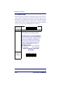
Sets the ACK character from the set of ASCII characters or any decimal value from 000 to 255. Pad
entries of less than three digits with zeros, as in
“005”. To configure this feature, scan the “START/
END” bar code above to place the unit in Programming Mode, then the “Set ACK Character,” followed
by the three digits (zero padded) from the Alphanumeric table in Appendix C, Alpha-Numeric Pad
representing your desired character. Exit programming mode by scanning the “START/END” bar code
above.
DEFAULT SETTING FOR THIS FEATURE: 006 (ACK)
Set ACK
Character
3-24
PowerScan® 7000BT SRI
Interface Features
RS-232 Interface Features — cont.
NAK Character
START/END
MODE
BAR CODE
Sets the NAK character from the set of ASCII characters or any decimal value from 000 to 255. Pad
entries of less than three digits with zeros, as in
“005”. To configure this feature, scan the “START/
END” bar code above to place the unit in Programming Mode, then the “Set NAK Character,” followed
by the three digits (zero padded) from the Alphanumeric table in Appendix C, Alpha-Numeric Pad
representing your desired character. Exit programming mode by scanning the “START/END” bar code
above.
DEFAULT SETTING FOR THIS FEATURE: 021 (!)
Set NAK
Character
Product Reference Guide
3-25
Interface Related Features
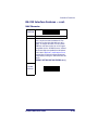
RS-232 Interface Features — cont.
Retry on ACK NAK Timeout
Enables/disables retry after the configurable ACK NAK Timeout Value
(set in the following feature) has expired.
START/END
STATE
BAR CODE
Disable Retry
on ACK NAK
Timeout
Enable Retry
on ACK NAK
Timeout
3-26
PowerScan® 7000BT SRI
Interface Features
RS-232 Interface Features — cont.
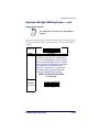
ACK NAK Timeout Value
START/END
MODE
BAR CODE
This item specifies the time the scanner will wait for
an ACK character from the host following a label
transmission.
000 = Infinite timeout
001 - 075 = Timeout in 200-millisecond increments
To configure this feature, scan the “START/END” bar
code above to place the unit in Programming Mode,
then the “Set ACK NAK Timeout Value,” followed by
the three digits (zero padded) from the Alphanumeric
table in Appendix C, Alpha-Numeric Pad representing your desired value. Exit programming mode
by scanning the “START/END” bar code above
DEFAULT SETTING FOR THIS FEATURE: 001
Set ACK
NAK Timeout
Value
Product Reference Guide
3-27
Interface Related Features
RS-232 Interface Features — cont.
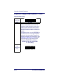
ACK NAK Retry Count
START/END
MODE
BAR CODE
This feature sets the number of times for the scanner
to retry a label transmission under a retry condition.
000 = No retry
001 - 254 = Retry for the specified number of times
255 = Retry forever
To configure this feature, scan the “START/END” bar
code above to place the unit in Programming Mode,
then the “Set ACK NAK Retry Count,” followed by the
three digits (zero padded) from the Alphanumeric
table in Appendix C, Alpha-Numeric Pad representing your desired retry count. Exit programming
mode by scanning the “START/END” bar code
above.
DEFAULT SETTING FOR THIS FEATURE: 003
Set ACK
Nak Retry
Count
3-28
PowerScan® 7000BT SRI
Interface Features
RS-232 Interface Features — cont.
ACK NAK Error Handling
This item specifies the method the scanner will use to handle errors
detected while waiting to receive the ACK character from the host.
Errors include unrecognized host commands and communication errors
such as parity or framing errors. Choices are:
00 = Ignore errors detected (recommended setting)
01 = Process error as valid ACK character (risk of lost label data)
02 = Process error as valid NAK character (risk of duplicate label data)
START/END
STATE
BAR CODE
Ignore Errors
Detected
Process error
as valid ACK
character
Process error
as valid NAK
character
Product Reference Guide
3-29
Interface Related Features
RS-232 Interface Features — cont.
Transmission Failure Indication
Enables/disables bad-label indication upon transmission failure.
START/END
STATE
BAR CODE
Disable
Transmission
Error Indication
Enable
Transmission
Error
Indication
3-30
PowerScan® 7000BT SRI
Interface Features
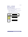
IBM-USB Interface Features
IBM-USB Device usage
The IBM-USB protocol allows for the scanner to be identified as one of
two different types of bar code scanners. Depending on what other scanners you may already have connected to a IBM-USB POS, you may need
to change this setting to enable all devices to communicate. Options are:
•
Table Top Scanner
•
Handheld Scanner
START/END
STATE
BAR CODE
Configure as
Table Top
Scanner
Configure as
Handheld
Scanner
Product Reference Guide
3-31
Interface Related Features
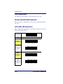
IBM
IBM Transmit Labels in Code 39 Format
This feature enables/disables scanner's ability to set a symbology identifier for a specified label to Code 39 before transmitting that label data to an IBM host. This applies to: Code 128,
Codabar and Code 93 for IBM USB; Code 128, Codabar and
Code 93 for IBM Port 5B; and Codabar and Code 93 for IBM
Port 9B.
START/END
STATE
BAR CODE
Disable
Convert to
Code 39
Enable Convert
to Code 39
3-32
PowerScan® 7000BT SRI
Interface Features
Wand Emulation
Supported Symbologies
The Wand Emulation interface will transmit bar code data as a wand
device would. This interface will transmit the following bar code symbologies:
•
UPC/EAN
•
UPC/EAN with addons
•
Code 39
•
Full ASCII Code 39
•
Interleaved 2 of 5
•
Codabar
•
Code 128
Pharmacode 39 is transmitted as Code 39, all other bar code symbology
types read by the scanner will be transmitted as Code 128.
Wand Emulation Bar Code Format
The following format settings are required for the wand emulation interface. These settings have been pre-configured at the factory for Wand
Emulation scanners.
•
UPC-A bar codes must include all 12 digits.
•
UPC-E bar codes must contain 8 digits, including a system digit, 6
data digits, and the check digit.
•
EAN-13 bar codes must have all 13 digits.
•
EAN-8 bar codes must include all 8 digits.
•
Code 39, Code 39 Full ASCII, and Pharmacode 39 bar codes must
NOT contain start / stop characters.
•
Codabar bar codes must include the start / stop characters, presented in the ABCD format.
•
Interleaved 2 of 5 bar codes must have an even number of digits.
Product Reference Guide
3-33
Interface Related Features
Wand Emulation — cont.
Bar/Space Polarity
Low/High — Black will be transmitted as a low voltage level (0 to
+0.7V) and space as high level (+2.4 to +5.25V).
High/Low — Black will be transmitted as a high voltage level (+2.4 to
+5.25V) and space as low level (0 to +0.7V).
Wand Idle State
This feature specifies the level of the wand output signal when idle. TTL
logic levels:
High voltage level (+2.4 to +5.25V)
Low voltage level (0 to +0.7V).
START/END
STATE
BAR CODE
Bar/Space =
Low/High
Bar/Space =
High/Low
3-34
PowerScan® 7000BT SRI
Interface Features
Wand Emulation — cont.
START/END
STATE
BAR CODE
Wand Idle
State = Low
Wand Idle State
= High
Product Reference Guide
3-35
Interface Related Features
Wand Emulation — cont.
Signal Speed
The speed of the transmission can be set. This selects the width of the
minimum narrow bar.
330 microseconds
660 microseconds
START/END
STATE
BAR CODE
Signal Speed =
330mS
Signal Speed =
660mS
3-36
PowerScan® 7000BT SRI
Interface Features
Wand Emulation — cont.
Transmit Trailing Noise
Enables/disables the ability of the scanner to generate noise transitions
after label transitions in the signal are transmitted to the host.
START/END
STATE
BAR CODE
Disable
Trailing Noise
Enable Trailing
Noise
Product Reference Guide
3-37
Interface Related Features
Wand Emulation — cont.
Transmit Leading Noise
Enables/disables ability of scanner to generate noise transitions before
label transitions in signal transmitted to host.
START/END
STATE
BAR CODE
Disable
Leading Noise
Enable Leading Noise
3-38
PowerScan® 7000BT SRI
Interface Features
Symbology Conversion
Wand Emulation can convert all bar codes to a single symbology.
Choices are:
•
No Conversion
•
Convert to Code 39
•
Convert to Code 128
START/END
STATE
BAR CODE
No Symbology
Conversion
Convert to C39
Convert to
C128
Product Reference Guide
3-39
Interface Related Features
Keyboard Wedge/USB Keyboard
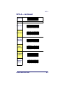
As a keyboard interface, the scanner supports most popular PCs and
IBM terminals. The installation of the wedge is a fairly simple process
that doesn’t require any changes of software or hardware.
NOTE
All of the options in this section apply to the Keyboard Wedge, however, only Keyboard Layout, Caps
Lock State and Control Characters apply to USB Keyboard.
Keyboard Layout
The Keyboard Layout option supports many countries. For details about
Keyboard Layout, please refer to your operating system manual.
START/END
STATE
BAR CODE
USA
Belgium
Britain
Denmark
3-40
PowerScan® 7000BT SRI
Interface Features
Keyboard Wedge/USB Keyboard — cont.
START/END
STATE
BAR CODE
France
Germany
Italy
Norway
Portugal
Spain
Sweden
Product Reference Guide
3-41
Interface Related Features
Keyboard Wedge/USB Keyboard — cont.
START/END
STATE
BAR CODE
Switzerland
Japan 106 Key
Hungary
Czech
Slovakia
Romania
3-42
PowerScan® 7000BT SRI
Interface Features
Keyboard Wedge/USB Keyboard — cont.
START/END
STATE
BAR CODE
Croatia
Poland
Product Reference Guide
3-43
Interface Related Features
Keyboard Wedge/USB Keyboard — cont.
Caps Lock State
Specifies which format the scanner sends character data.
START/END
STATE
BAR CODE
Disable Caps
Lock
Caps Lock “ON”
Shift Lock “ON”
3-44
PowerScan® 7000BT SRI
Interface Features
Keyboard Wedge/USB Keyboard — cont.
Keyboard Simulation
This feature does not apply to the USB Keyboard
interface.
NOTE
All PCs check the keyboard status during the power-on Selftest. It is recommended that you enable this function if you are working without a
keyboard installation. It simulates keyboard timing and passes the keyboard status to the PC during power-on.
Control Characters
Specifies how the scanner transmits ASCII control characters to the host.
Choices are:
•
Disable Control Characters
•
Enable transmission of control characters to host
•
Send characters between 00H and 1FH according to a special
function-key mapping table. (This is used to send keys that are not
in the normal ASCII set; a unique set is provided for each available
scancode set. Reference Appendix E, Keyboard Function Key Mappings.)
Product Reference Guide
3-45
Interface Related Features
Keyboard Wedge/USB Keyboard — cont.
START/END
STATE
BAR CODE
Disable
Keyboard
Simulation
Enable
Keyboard
Simulation
Disable
Control
Characters
Enable
Transmission of
Control
Characters
Enable
Function Key
Mapping
3-46
PowerScan® 7000BT SRI
Interface Features
Keyboard Wedge/USB Keyboard — cont.
Wedge Quiet Interval
This feature does not apply to the USB Keyboard
interface.
NOTE
Quiet Interval is the amount of time to look for keyboard activity before
the scanner breaks the keyboard connection in order to transmit data to
the host..
START/END
MODE
BAR CODE
Selectable from 000 (no interval) to 255 in 10 msec
increments to set the interval. To configure this feature, scan the “START/END” bar code above to place
the unit in Programming Mode, then the Set Wedge
Quiet Interval bar code followed by the three digits
(zero padded) from the Alphanumeric table in
Appendix C, Alpha-Numeric Pad representing
your desired length. Exit programming mode by
scanning the “START/END” bar code above.
DEFAULT SETTING FOR THIS FEATURE:
010 (100 msec)
Set Wedge
Quiet Interval
Product Reference Guide
3-47
Interface Related Features
Keyboard Wedge/USB Keyboard — cont.
Intercharacter Delay
START/END
MODE
BAR CODE
One-half of the delay specified below is inserted
between scancodes within each character. If the
transmission speed is too high, the system may not
be able to receive all characters. You may need to
adjust the delay to make the system work properly.
Selectable from 00 to 99 in 10msec increments to set
the delay.
To configure this feature, scan the “START/END” bar
code above to place the unit in Programming Mode,
then the “Set Intercharacter Delay,” followed by the
two digits (zero padded) from the Alphanumeric table
in Appendix C, Alpha-Numeric Pad representing
your desired length. Exit programming mode by
scanning the “START/END” bar code above.
DEFAULT SETTING FOR THIS FEATURE:
01 (10mSec Delay)
Set
Intercharacter
Delay
3-48
PowerScan® 7000BT SRI
Chapter 4
Data Editing
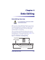
Data Editing Overview
It is not recommended to use these features with IBM
or Wand Emulation interfaces.
CAUTION
When a bar code is scanned, additional information can be sent to the
host computer along with the bar code data. This combination of bar
code data and supplementary user-defined data is called a “message
string.” The features in this chapter can be used to build specific
user-defined data into a message string.
There are several types of selectable data characters that can be sent
before and after scanned data. You can specify if they should be sent
with all symbologies, or only with specific symbologies. Figure 4-1 shows
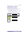
the available elements you can add to a message string:
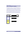
Figure 4-1. Breakdown of a Message String
Label ID Transmission:
Enable this option to
transmit the Label ID you
configure for the scanned
symbology.
Prefix
Label ID
OR...
AIM ID
Bar Code Data
Label ID
Suffix
AIM ID: This function is used to identify and display the
common label identifier for its symbology. When enabled,
this ID code will be transmitted before the scanned bar
code data.
00 - 20 Characters (ASCII)
Product Reference Guide
4-1
Data Editing
Please Keep In Mind...
•
Modifying a message string is not a mandatory requirement. Data
editing is a sophisticated feature allowing highly customizable output for advanced users. Factory default settings for data editing is
typically set to NONE.
•
A prefix or suffix may be applied (reference the Symbologies chapter for these settings) across all symbologies (set via the Global features in this chapter).
•
You can add any character from the ASCII Chart (from 00-FF hex)
on the inside back cover of this manual as a prefix, suffix or Label
ID.
•
Enter prefixes and suffixes in the order in which you want them to
appear on the output.
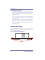
Global Prefix/Suffix
Up to 20 ASCII characters may be added as a prefix (in a position before
the bar code data) and/or as a suffix (in a position following the bar code
data) as indicated in Figure 4-2.
Figure 4-2. Prefix and Suffix Positions
OR...
Prefix
Label ID
AIM ID
Bar Code Data
Label ID
Suffix
00 - 20 Characters (ASCII)
AND
OR
4-2
PowerScan® 7000BT SRI
Global Prefix/Suffix
Global Prefix/Suffix — continued
Example: Setting a Prefix
In this example, we’ll set a prefix for all symbologies.
1. Determine which ASCII character(s) are to be added to scanned
bar code data. In this example, we’ll add a dollar sign (‘$’) as a prefix.
2. Scan the START bar code.
3. Scan the SET PREFIX bar code.
4. Reference the ASCII Chart on the inside back cover of this manual,
to find the hex value assigned to the desired character. The corresponding hex number for the ‘$’ character is 24. To enter this
selection code, scan the ‘2’ and ‘4’ bar codes from Appendix C,
Alpha-Numeric Pad.
5. Scan the END bar code to exit Programming Mode.
If less than the expected string of 20 characters are
selected, scan the END bar code twice to accept the
selections and exit Programming Mode.
NOTE
6. The resulting message string would appear as follows:
Scanned bar code data:
12345
Resulting message string output: $12345
Product Reference Guide
4-3
Data Editing
Global Prefix/Suffix — continued
START
MODE
BAR CODE
Sets up to 20 characters each from the set of ASCII
characters or any hex value from 00 to FF. To configure this feature, scan the “START” bar code above to
place the unit in Programming Mode, then the “Set
Prefix” or “Set Suffix,” followed by the alpha-numeric
characters from the Alphanumeric table in
Appendix C, Alpha-Numeric Pad representing
your desired character(s). Reference the section,
Example: Setting a Prefix, for more information.
Exit programming mode by scanning the “END” bar
code below (scan “END” twice if less than 20 characters have been selected).
DEFAULT SETTING FOR THIS FEATURE:
00 Hex (None)
Set Prefix
Set Suffix
END
4-4
PowerScan® 7000BT SRI
AIM ID
AIM ID
AIM label identifiers (as opposed to custom characters you select yourself as with label identifiers) can be included with scanned bar code data.
AIM label identifiers consist of three characters as follows:
•
A close brace character (ASCII ‘]’), followed by...
•
A code character (see the table below), followed by
•
A modifier character (the modifier character is symbol dependent)
SYMBOLOGY
CHAR
SYMBOLOGY
CHAR
UPC/EAN
E
MSI/Plessey
M
Code 39
A
PDF 417 & Micro PDF 417
L
Codabar
F
RSS (RSS-14, RSS
Expanded, RSS Limited)
e
Interleaved.2 of 5
I
Standard 2 of 5
S
Code 93
G
ISBN
Xa
Code 128/EAN 128
C
a. ISBN (X with a 0 modifier character)
Figure 4-3. AIM ID
Prefix
Label ID
AIM ID
Product Reference Guide
Bar Code Data
Label ID
Suffix
4-5
Data Editing
AIM ID — continued
START
STATE
BAR CODE
Disable AIM ID
Enable AIM ID
END
4-6
PowerScan® 7000BT SRI
Label ID
Label ID
A Label ID is a customizable code of up to two ASCII characters (00FF), used to identify a bar code (symbology) type. It can be appended
previous to or following the transmitted bar code data depending upon
how this option is enabled. This feature provides options for configuring
custom Label IDs individually per symbology. If you wish to program
the scanner to always include an industry standard label identifier for
ALL symbology types, see the previous feature, AIM ID.
To configure a Label ID:
1. Scan the START bar code.
2. Select Label ID position as either BEFORE or AFTER by scanning the appropriate bar code.
3. Scan a bar code to select the symbology for which you wish to configure a custom Label ID.
4. Determine the desired character(s) (you may choose either one or
two) which will represent the Label ID for the selected symbology.
Next, turn to the ASCII Chart on the inside back cover of this manual and find the equivalent hex digits associated with your choice
of Label ID. For example, if you wish to select an equal sign (=) as
a Label ID, the chart indicates its associated hex characters as 3D.
5. Turn to Appendix C, Alpha-Numeric Pad and scan the bar codes representing the hex characters determined in the previous step. For
the example given, the characters ‘0’, ‘0’, ‘3’ and ‘D’ would be
scanned. The two zeros scanned (‘0’, ‘0’) represent a selection of
“no character,” since this option allows for two Label ID characters. (Pad with zeros to enter four hex characters.)
6. Scan the END bar code to exit programming mode.
Figure 4-4. Label ID Position Options
Prefix
Label ID
Aim ID
Bar Code Data
Label ID
Suffix
OR
Product Reference Guide
4-7
Data Editing
Label ID — continued
START
OPTION
BAR CODE
Label ID
Transmission:
Disable
Label ID
Position:
Before Bar
Code Data
Label ID
Position: After
Bar Code Data
Set UPC-A
Label ID
Character(s)
DEFAULT SETTING FOR THIS FEATURE: 41 Hex (A)
Set UPC-A
w/P2 Addon
Label ID
Character(s) DEFAULT SETTING FOR THIS FEATURE: 41 Hex (A)
Set UPC-A
w/P5 Addon
Label ID
Character(s)
4-8
DEFAULT SETTING FOR THIS FEATURE: 41 Hex (A)
PowerScan® 7000BT SRI
Label ID
Label ID — continued
START
OPTION
BAR CODE
Set UPC-A
w/C128 Addon
Label ID
Character(s) DEFAULT SETTING FOR THIS FEATURE: 41 Hex (A)
Set UPC-E
Label ID
Character(s)
Set UPC-E
w/P2 Addon
Label ID
Character(s)
Set UPC-E
w/P5 Addon
Label ID
Character(s)
DEFAULT SETTING FOR THIS FEATURE: 45 Hex (E)
DEFAULT SETTING FOR THIS FEATURE: 45 Hex (E)
DEFAULT SETTING FOR THIS FEATURE: 45 Hex (E)
Set UPC-E
w/C128 Addon
Label ID
Character(s) DEFAULT SETTING FOR THIS FEATURE: 45 Hex (E)
Set EAN-8
Label ID
Character(s)
Set EAN-8
w/P2 Addon
Label ID
Character(s)
DEFAULT SETTING FOR THIS FEATURE:
4646 Hex (FF)
DEFAULT SETTING FOR THIS FEATURE:
4646 Hex (FF)
Product Reference Guide
4-9
Data Editing
Label ID — continued
START
OPTION
Set EAN-8
w/P5 Addon
Label ID
Character(s)
Set EAN-8
w/C128 Addon
Label ID
Character(s)
Set EAN-13
Label ID
Character(s)
BAR CODE
DEFAULT SETTING FOR THIS FEATURE:
4646 Hex (FF)
DEFAULT SETTING FOR THIS FEATURE:
4646 Hex (FF)
DEFAULT SETTING FOR THIS FEATURE: 46 Hex (F)
Set EAN-13
w/P2 Addon
Label ID
Character(s) DEFAULT SETTING FOR THIS FEATURE: 46 Hex (F)
Set EAN-13
w/P5 Addon
Label ID
Character(s) DEFAULT SETTING FOR THIS FEATURE: 46 Hex (F)
Set EAN-13
w/C128 Addon
Label ID
Character(s) DEFAULT SETTING FOR THIS FEATURE: 46 Hex (F)
Set ISBN
Label ID
Character(s)
DEFAULT SETTING FOR THIS FEATURE: 49 Hex (I)
4-10
PowerScan® 7000BT SRI
Label ID
Label ID — continued
START
OPTION
Set GTIN
Label ID
Character(s)
Set GTIN
w/P2 addon
Label ID
Character(s)
Set GTIN
w/P5 addon
Label ID
Character(s)
Set GTIN
w/C128 addon
Label ID
Character(s)
Set RSS-14
Label ID
Character(s)
Set RSS-14
Composite
Label ID
Character(s)
BAR CODE
DEFAULT SETTING FOR THIS FEATURE:47 Hex (G)
DEFAULT SETTING FOR THIS FEATURE:
4732 Hex (G2)
DEFAULT SETTING FOR THIS FEATURE:
4735 Hex (G5)
DEFAULT SETTING FOR THIS FEATURE:
4738 Hex (G8)
DEFAULT SETTING FOR THIS FEATURE:
5234 Hex (R4)
DEFAULT SETTING FOR THIS FEATURE:
5234 Hex (R4)
Product Reference Guide
4-11
Data Editing
Label ID — continued
START
OPTION
Set RSS
Expanded
Label ID
Character(s)
Set RSS
Expanded
Composite
Label ID
Character(s)
Set RSS
Limited
Label ID
Character(s)
Set RSS
Limited
Composite
Label ID
Character(s)
Set Code 39
Label ID
Character(s)
4-12
BAR CODE
DEFAULT SETTING FOR THIS FEATURE:
5258 Hex (RX)
DEFAULT SETTING FOR THIS FEATURE:
5258 Hex (RX)
DEFAULT SETTING FOR THIS FEATURE:
524C Hex (RL)
DEFAULT SETTING FOR THIS FEATURE:
524C Hex (RL)
DEFAULT SETTING FOR THIS FEATURE:
2A Hex (*)
PowerScan® 7000BT SRI
Label ID
Label ID — continued
START
OPTION
BAR CODE
Set
Pharmacode 39
Label ID
Character(s) DEFAULT SETTING FOR THIS FEATURE: 41 Hex (A)
Set Code 128
Label ID
Character(s)
DEFAULT SETTING FOR THIS FEATURE: 23 Hex (#)
Set I 2 of 5
Label ID
Character(s)
DEFAULT SETTING FOR THIS FEATURE: 69 Hex (i)
Set
Codabar
Label ID
Character(s) DEFAULT SETTING FOR THIS FEATURE:25 Hex (%)
Set
Code 93 Label
ID
Character(s) DEFAULT SETTING FOR THIS FEATURE: 26 Hex (&)
Set
Code 11 Label
ID
Character(s)
DEFAULT SETTING FOR THIS FEATURE:
4345 Hex (CE)
Product Reference Guide
4-13
Data Editing
Label ID — continued
START
OPTION
Set
MSI/Plessey
Label ID
Character(s)
Set
Std 2 of 5
Label ID
Character(s)
Set
PDF 417
Label ID
Character(s)
BAR CODE
DEFAULT SETTING FOR THIS FEATURE:
40 Hex (@)
DEFAULT SETTING FOR THIS FEATURE: 69 Hex (i)
DEFAULT SETTING FOR THIS FEATURE: 50 Hex (P)
Set
Micro PDF 417
Label ID
Character(s) DEFAULT SETTING FOR THIS FEATURE: 6D50 Hex
(mP)
END
4-14
PowerScan® 7000BT SRI
Label ID
Case Conversion
This feature can convert scanned bar code data to either all lower case or
all upper case characters.
Case conversion affects ONLY scanned bar code data,
and does not affect Label ID, Prefix, Suffix, or other
appended data.
NOTE
START
MODE
BAR CODE
Disable
Convert to
Upper Case
Convert to
Lower Case
END
Product Reference Guide
4-15
Data Editing
Character Conversion
Character conversion is an eight byte configuration item. The eight
bytes are 4 character pairs represented in hexadecimal ASCII values. The
first character in the pair is the character that will be converted. The second character in the pair is the character to convert to. If the character
to convert in a pair is FF, then no conversion is done.
For example, if you have the character conversion configuration item set
to the following: 41423132FFFFFFFF
The first pair is 4142 or AB (41 hex is an ASCII capital A, 42 hex is an
ASCII capital B) and the second pair is 3132 or 12 (31 hex is an ASCII
1, 32 is an ASCII 2). The other two pairs are FFFF and FFFF.
With the label, AB12BA21, it would look as follows after the character
conversion: BB22BB22.
The A characters were converted to B characters and the 1 characters
were converted to 2 characters. Nothing is done with the last two character pairs, since they are all FF.
To set Character Conversion:
1. Scan the START bar code.
2. Scan the Character Conversion bar code.
3. Determine the desired string. Sixteen positions must be determined as in the above example. Next, turn to the ASCII Chart on
the inside back cover of this manual and find the equivalent hex
digits needed to fulfill the string.
4. Turn to Appendix C, Alpha-Numeric Pad and scan the bar codes representing the hex characters determined in the previous step.
5. Scan the END bar code to exit Programming Mode.
If less than the expected string of 16 characters are
selected, scan the END bar code twice to accept the
selections and exit Programming Mode.
NOTE
Scan the END bar code to exit programming mode.
4-16
PowerScan® 7000BT SRI
Label ID
Character Conversion — continued
START
MODE
Character
Conversion
BAR CODE
DEFAULT SETTING FOR THIS FEATURE:
FFFFFFFFFFFFFFFF Hex (no conversion)
END
Product Reference Guide
4-17
Data Editing
NOTES
4-18
PowerScan® 7000BT SRI
Chapter 5
Bluetooth Features
This section contains features which are specific to radio communications between the scanner and Base Station or PC. When linked with a
Base Station or PC, the scanner will read and decode bar codes (labels)
and transmit them to the selected device via a Bluetooth radio.
Product Reference Guide
5-1
Bluetooth Features
Auto Configuration Update
When this feature is enabled, a scanner and its linked Base Station can
automatically ensure they stay in sync with regard to configuration. This
is accomplished by the linked scanner and Base Station comparing their
configuration file check sum. If either is different, the Base Station will
automatically update the scanner with its configuration. If the units are
linked, any changes made to the Base Station configuration through the
scan utility software will automatically be sent to the scanner at the completion of the programming session. By the same token, any changes
made to the linked scanner’s configuration will automatically be transmitted to the Base Station when the scanner exits Programming Mode.
START/END
STATE
BAR CODE
Disable Auto
Configuration
Enable Auto
Configuration
5-2
PowerScan® 7000BT SRI
Auto Flash Memory Update
Auto Flash Memory Update
Enable this feature to allow the Base Station to automatically update a
linked scanner’s flash memory to the version in the Base Station.
START/END
STATE
BAR CODE
Disable Auto
Flash Update
Enable Auto
Flash Update
Product Reference Guide
5-3
Bluetooth Features
Non-Automatic Updates
Use the following special programming bar code labels to perform a
manual, one-time update to devices as listed.
Flash Update to Scanner
Scan this programming bar code to copy the Base Station’s flash memory
to the scanner. Use this method when the Auto Flash Memory Update feature is disabled and you want a one-time flash update to be performed.
Flash Update to Scanner
Copy Configuration to Scanner
Scan the following label to copy the current Base Station configuration
to the scanner. Use this method when the Auto Configuration Update feature is disabled and you want a one-time configuration update to be performed to the scanner.
Copy Configuration to Scanner
Copy Configuration to Base Station
Scan the following label to copy the current scanner configuration to the
Base Station. Use this method when the Auto Configuration Update feature
is disabled and you want a one-time configuration update to be performed to the Base Station.
Copy Configuration to Base Station
5-4
PowerScan® 7000BT SRI
Battery Charge Mode
Do Not Send Configuration to Scanner
In instances where you do not want the Base Station to automatically
update the scanner’s configuration (for example if your scanner contains
a desired custom configuration but will temporarily be used with a Base
Station containing an alternate configuration), scan the label below prior
to linking the units to ensure the scanner configuration will not be overwritten by the Base Station.
Do Not Send Configuration to Scanner
Battery Charge Mode
The Base Station’s ability to charge a Battery Pack (while installed in a
scanner seated in the Base Station) can be controlled using this feature.
START/END
STATE
BAR CODE
Low Charge
High Charge
Charger
Disabled
Product Reference Guide
5-5
Bluetooth Features
ACK Timeout
ACK Timeout configures a duration, selectable in 200-millisecond
increments, for the scanner to wait for the Base Station to accept the data
and respond with an ACK (acknowledge) or NAK (when data is in
error).
Upon expiration of the timeout, the scanner will emit a transmission
error beep and return to its normal operating mode.
START/END
MODE
BAR CODE
Sets the ACK Timeout using a decimal value from
000 to 255. Settings are in 200 millisecond increments. A setting of 000 disables the timeout.
To configure this feature, scan the “START/END” bar
code above to place the unit in Programming Mode,
then the “Set ACK Timeout,” followed by the three
digits (zero padded) from the Alphanumeric table in
Appendix C, Alpha-Numeric Pad representing
your setting. Exit programming mode by scanning the
“START/END” bar code above.
SETTINGS EXAMPLES:
000 = Wait Forever
007 = 1.4 seconds
158 = 31.6 seconds 255 = 51 seconds
DEFAULT SETTING FOR THIS FEATURE:
000 (Disable)
Set
ACK Timeout
5-6
PowerScan® 7000BT SRI
Poll Rate Timeout
Poll Rate Timeout
During normal operation, the Base Station regularly signals (polls) for a
response from the scanner in order to ensure the linked scanner is still in
communication. This rate is set in 10 millisecond increments between
polls. A value of 000 selects the minimum timeout1 of 1.25 milliseconds.
START/END
MODE
BAR CODE
Sets the Poll RateTimeout using a value from 000 to
100. Settings are in 10 millisecond increments.
To configure this feature, scan the “START/END” bar
code above to place the unit in Programming Mode,
then the “Set Poll Rate Timeout,” followed by the
three characters (zero padded) from the Alphanumeric table in Appendix C, Alpha-Numeric Pad
representing your setting. Exit programming mode by
scanning the “START/END” bar code above.
SETTINGS EXAMPLES:
000 = 1.25 milliseconds 007 = 70 milliseconds
012 = 120 milliseconds 100 = 1 second
DEFAULT SETTING FOR THIS FEATURE:
002 (20 milliseconds)
Set
Poll Timeout
1. Shortest time between polls. This is the fastest rate selectable.
Product Reference Guide
5-7
Bluetooth Features
Transmit HACK
This option allows you to choose when the HACK (Host Acknowledge)
should be sent from the Base Station to the scanner.
Choices are:
•
OPTION #1 — Send HACK as soon as the Base Station receives a
label, or...
•
OPTION #2 — Send HACK as soon as the Base Station completes transmission to the host.
START/END
STATE
BAR CODE
HACK
Option #1
HACK
Option #2
5-8
PowerScan® 7000BT SRI
Bluetooth (BT) Beeper Features
Bluetooth (BT) Beeper Features
The settings in this section apply specifically to scanner beep indications
associated with communications between the scanner and Base Station1
or other device it is linked to.
BT Beep Volume
This option selects the volume (loudness/softness) of the Acknowledge
(ACK) Label beep.
START/END
STATE
BAR CODE
BT Beep
Volume
= LOW
BT Beep
Volume
= MEDIUM
BT Beep
Volume
= HIGH
1. The Base Station does not include a beeper.
Product Reference Guide
5-9
Bluetooth Features
BT Beep Duration
Use this feature to set the duration of configurable BT-specific beeps.
Settings are in increments of 10 milliseconds.
START/END
MODE
BAR CODE
Sets the BT Beep Duration using a value from 001 to
255. Settings are in 10 millisecond increments.
To configure this feature, scan the “START/END” bar
code above to place the unit in Programming Mode,
then the “Set BT Beep Duration,” followed by the
three characters (zero padded) from the Alphanumeric table in Appendix C, Alpha-Numeric Pad
representing your setting. Exit programming mode by
scanning the “START/END” bar code above.
SETTINGS EXAMPLES:
007 = 70 milliseconds
042 = 420 milliseconds
158 = 1.58 seconds 255 = 2.55 seconds
DEFAULT SETTING FOR THIS FEATURE:
006 (80 milliseconds)
Set BT
Beep Duration
5-10
PowerScan® 7000BT SRI
Bluetooth (BT) Beeper Features
BT Beep Frequency
This option selects the frequency (tone or pitch) of the Acknowledge
(ACK) Label beep.
START/END
STATE
BAR CODE
BT Beep
Frequency
= LOW
BT Beep
Frequency
= MEDIUM
BT Beep
Frequency
= HIGH
Product Reference Guide
5-11
Bluetooth Features
BT Disconnect Beep
When enabled, this option allows the scanner to sound (beep) when the
scanner disconnects from the Base Station due to out of range, low
power, etc.
START/END
STATE
BAR CODE
Disable
Disconnect
Beep
Enable
Disconnect
Beep
5-12
PowerScan® 7000BT SRI
Bluetooth (BT) Beeper Features
BT ACK Label Beep
This setting enables or disables the acknowledgement (ACK) beep that
indicates a label has been sent to the Base Station, which has accepted
the data and responded.
START/END
STATE
BAR CODE
Disable
ACK Label
Beep
Enable
ACK Label
Beep
Product Reference Guide
5-13
Bluetooth Features
BT Transmission Error Beep
Enables or disables the transmission error Beep. This beep indicates a
label has been sent to but not acknowledged by the Base Station (ACK
Timeout occurred).
START/END
STATE
BAR CODE
Disable
Transmission
Error Beep
Enable
Transmission
Error Beep
5-14
PowerScan® 7000BT SRI
Bluetooth (BT) Beeper Features
BT In Cradle Chirp
This feature enables or disables a “chirp” sound (a short, high-pitched
beep) to indicate when the scanner is fully seated in position in the Base
Station.
START/END
STATE
BAR CODE
Disable
In Cradle Chirp
Enable
In Cradle
Chirp
Product Reference Guide
5-15
Bluetooth Features
BT Leash Beep
This feature enables or disables the Leash Beep, which occurs upon disconnect. When enabled, the scanner will beep three times per second for
the number of seconds defined in this setting to notify if a linked scanner
is leaving the immediate vicinity of the Base Station1. This is especially
useful in instances where a scanner might inadvertently have been placed
in a bag or cart. A setting of 000 disables the Leash Beep.
START/END
MODE
BAR CODE
Sets the BT Leash Beep using a hex value from 000
to 255. Settings are in one second increments.
To configure this feature, scan the “START/END” bar
code above to place the unit in Programming Mode,
then the “Set BT Leash Beep,” followed by the three
characters (zero padded) from the Alphanumeric
table in Appendix C, Alpha-Numeric Pad representing your setting. Exit programming mode by
scanning the “START/END” bar code above.
SETTINGS EXAMPLES:
000 = Disable Leash Beep 015 = 15 seconds
042 = 42 seconds
255 = 4 min 15 sec
DEFAULT SETTING FOR THIS FEATURE:
000 (Disabled)
Set BT
Leash Beep
1. The Base Station does not include a beeper. Only the scanner will beep to indicate.
5-16
PowerScan® 7000BT SRI
Chapter 6
Symbologies
The scanner supports the following symbologies (bar code types).
Options for each symbology are included in this chapter.
·UPC-A
·Pharmacode 39
·UPC-E
·Code 128 and EAN 128
·EAN-13
·Interleaved 2 of 5
·EAN-8
·Codabar
·RSS-14
·Code 93
·RSS Expanded
·Code 11
·RSS Limited
·MSI/Plessey
·Code 39
·Standard 2 of 5
2D Symbologies
·PDF 417
·Micro PDF 417
Factory Defaults — are indicated in bold text and are highlighted
with yellow throughout this section.
Product Reference Guide
6-1
Symbologies
UPC-A
The following options apply to the UPC-A symbology.
Disable/Enable UPC-A
When disabled, the scanner will not read UPC-A bar codes.
Check Digit Transmission
Enable this option to transmit the check digit along with UPC-A bar
code data.
Expand UPC-A to EAN-13
Expands UPC-A data to the EAN-13 data format. Selecting this feature
also changes the symbology ID to match those required for EAN-13.
System Number Transmission
This feature enables/disables transmission of UPC-A System Number.
6-2
PowerScan® 7000BT SRI
UPC-A
UPC-A — continued
START/END
STATE
BAR CODE
Disable UPC-A
Enable UPC-A
Don’t Send
Check Digit
Send
Check Digit
Don’t Expand
to EAN-13
Expand to
EAN-13
Product Reference Guide
6-3
Symbologies
UPC-A — continued
START/END
STATE
BAR CODE
Disable System Number
Transmission
Enable System
Number Transmission
6-4
PowerScan® 7000BT SRI
UPC-A
UPC-A — continued
UPC-A Minimum Reads
This feature specifies the minimum number of consecutive times a UPCA label must be decoded before it is accepted as good read.
START/END
READS
BAR CODE
Minimum =
1 Read
Minimum =
2 Reads
Minimum =
3 Reads
Minimum =
4 Reads
Product Reference Guide
6-5
Symbologies
UPC-A — continued
In-store Minimum Reads
This feature specifies the minimum number of consecutive times an instore printed label must be decoded before it is accepted as good read.
START/END
READS
BAR CODE
Minimum =
1 Read
Minimum =
2 Reads
Minimum =
3 Reads
Minimum =
4 Reads
6-6
PowerScan® 7000BT SRI
UPC-A
UPC-A — continued
Add-On Timer
This feature sets the period of time after a UPC-A label is decoded when
optional add-on reading is enabled.
START/END
STATE
BAR CODE
This item is used to set the timer value when optional
add-ons are enabled. The selectable range is from
010 to 300 mSec in 10 mSec increments. To configure this feature, scan the “START” bar code above to
place the unit in Programming Mode, then the “AddOn Timer,” followed by the three digits (zero padded)
from the Alphanumeric table in Appendix C, AlphaNumeric Pad representing the disired timer setting.
Exit programming mode by scanning the “END” bar
code below.
Add-On Timer
DEFAULT SETTING FOR THIS FEATURE:
007 (70 milliseconds)
Product Reference Guide
6-7
Symbologies
UPC-E
The following options apply to the UPC-E symbology.
Disable/Enable UPC-E
When disabled, the scanner will not read UPC-E bar codes.
Check Digit Transmission
Enable this option to transmit the check digit along with UPC-E bar
code data.
System Number
The System Number (SN) which is usually a zero (0) in the leading position can be optionally included (or not) with scanned bar code data.
Expand UPC-E to UPC-A
Enables/disables expansion of UPC-E labels to UPC-A.
Expand UPC-E to EAN13
Adds a leading zero to a UPC-E bar code which ‘expands’ the data to the
EAN-13 data format. Selecting this feature also changes the symbology
ID to match those required for EAN-13.
6-8
PowerScan® 7000BT SRI
UPC-E
UPC-E — continued
START/END
STATE
BAR CODE
Disable UPC-E
Enable UPC-E
Don’t Send
Check Digit
Send
Check Digit
Exclude System Number
Include System
Number
Product Reference Guide
6-9
Symbologies
UPC-E — continued
START/END
STATE
BAR CODE
Don’t Expand
UPC-E to
UPC-A
Expand UPC-E
to UPC-A
Don’t Expand
UPC-E to
EAN-13
Expand UPC-E
to EAN-13
6-10
PowerScan® 7000BT SRI
UPC-E
UPC-E — continued
Minimum Reads
This feature specifies the minimum number of consecutive times a UPCE label must be decoded before it is accepted as good read.
START/END
READS
BAR CODE
Minimum =
1 Read
Minimum =
2 Reads
Minimum =
3 Reads
Minimum =
4 Reads
Product Reference Guide
6-11
Symbologies
GTIN
The following options apply to the GTIN label data format.
Disable/Enable GTIN
When this feature is enabled, the scanner will translate UPC/EAN labels
to the 14 digit GTIN format.
START/END
STATE
BAR CODE
Disable GTIN
Enable GTIN
6-12
PowerScan® 7000BT SRI
EAN-13
EAN-13
The following options apply to the EAN-13 symbology.
Disable/Enable EAN-13
When disabled, the scanner will not read EAN-13 bar codes.
Check Digit Transmission
Enable this option to transmit the check digit along with EAN-13 bar
code data.
EAN-13 Flag 1 Character
Enables/disables transmission of an EAN/JAN13 Flag1 character.
ISBN
When enabled, this feature truncates the leading three digits from labels
that contain ISBN (International Standard Book Number). These codes
are used for books and magazines. Labels with ISBN codes start with
"978".
Example:
Bar code data:
“9789572222720”
Output:
“9572222724”
Product Reference Guide
6-13
Symbologies
EAN-13 — continued
START/END
STATE
BAR CODE
Disable EAN-13
Enable EAN-13
Don’t Send
Check Digit
Send
Check Digit
Don’t Transmit
EAN-13 Flag 1
Char
6-14
PowerScan® 7000BT SRI
EAN-13
EAN-13 — continued
START/END
STATE
BAR CODE
Transmit
EAN-13 Flag 1
Char
Disable ISBN
Enable ISBN
Product Reference Guide
6-15
Symbologies
EAN-13 — continued
Minimum Reads
This feature specifies the minimum number of consecutive times an
EAN-13 label must be decoded before it is accepted as good read.
START/END
READS
BAR CODE
Minimum =
1 Read
Minimum =
2 Reads
Minimum =
3 Reads
Minimum =
4 Reads
6-16
PowerScan® 7000BT SRI
EAN-8
EAN-8
The following options apply to the EAN-8 symbology.
Disable/Enable EAN-8
When disabled, the scanner will not read EAN-8 bar codes.
Check Digit Transmission
Enable this option to transmit the check Digit along with EAN-8 bar
code data.
START/END
STATE
BAR CODE
Disable EAN-8
Enable EAN-8
Don’t Send
Check Digit
Send
Check Digit
Product Reference Guide
6-17
Symbologies
EAN-8 — continued
Expand EAN-8 to EAN-13 — Expands EAN-8 data to the EAN-13
data format. Selecting this feature also changes the symbology ID to
match those required for EAN-13.
START/END
STATE
BAR CODE
Don’t Expand
to EAN-13
Expand to
EAN-13
6-18
PowerScan® 7000BT SRI
EAN-8
EAN-8 — continued
Minimum Reads
This feature specifies the minimum number of consecutive times an
EAN-8 label must be decoded before it is accepted as good read.
START/END
READS
BAR CODE
Minimum =
1 Read
Minimum =
2 Reads
Minimum =
3 Reads
Minimum =
4 Reads
Product Reference Guide
6-19
Symbologies
Add-ons
Add-ons (or supplemental characters) are commonly added to the end of
UPC/EAN bar codes. The scanner will read the add-ons if they are
enabled and in the field of view. Three add-on types are supported: 2digit, 5-digit and Code 128 add-ons. Supported options are:
None — This option directs the scanner to ignore add-on portion of a
UPC/EAN bar code but still read the main portion of the bar code.
2 Digits — The scanner will optionally read 2-digit add-ons with the
UPC/EAN label.
5 Digits — The scanner will optionally read 5-digit add-ons with the
UPC/EAN label.
Code 128 Add-on — The scanner will optionally read Code 128 addons with the UPC/EAN label.
Contact Customer Support for advanced programming of
optional and conditional add-ons.
NOTE
6-20
PowerScan® 7000BT SRI
Add-ons
Add-ons — continued
START/END
STATE
BAR CODE
Disable
Optional 2Digit Add-ons
Enable Optional
2-Digit Add-ons
Disable
Optional 5Digit Add-ons
Enable Optional
5-Digit Add-ons
Disable
Optional Code
128 Add-ons
Enable Optional
Code 128
Add-ons
Product Reference Guide
6-21
Symbologies
RSS-14
The following options apply to the RSS-14 symbology.
Disable/Enable RSS-14
When this feature is disabled, the scanner will not read RSS-14 bar
codes.
UCC/EAN 128 Emulation
When enabled, RSS-14 bar codes will be translated to the UCC/EAN
128 label data format.
6-22
PowerScan® 7000BT SRI
RSS-14
RSS-14 — continued
START/END
STATE
BAR CODE
Disable
RSS-14
Enable RSS-14
Disable
UCC/EAN 128
Emulation
Enable
UCC/EAN 128
Emulation
Product Reference Guide
6-23
Symbologies
RSS-14 — continued
Minimum Reads
This feature specifies the minimum number of consecutive times an
RSS-14 label must be decoded before it is accepted as good read.
START/END
READS
BAR CODE
Minimum =
1 Read
Minimum =
2 Reads
Minimum =
3 Reads
Minimum =
4 Reads
6-24
PowerScan® 7000BT SRI
RSS-14
RSS-14 — continued
RSS-14 2D Component
This feature controls the requirement that a 2D label component be
decoded when an RSS-14 base label is decoded.
•
Enable — Requires that a 2D label component be decoded when
an RSS-14 base label is decoded.
•
Disable — Does NOT require a 2D label component to be
decoded when an RSS-14 base label is decoded.
START/END
STATE
BAR CODE
Disable
RSS-14 2D
Component
Enable RSS-14
2D Component
Product Reference Guide
6-25
Symbologies
RSS Expanded
The following options apply to the RSS Expanded symbology.
Disable/Enable RSS Expanded
When this feature is disabled, the scanner will not read RSS Expanded
bar codes.
UCC/EAN 128 Emulation
When enabled, RSS Expanded bar codes will be translated to the UCC/
EAN 128 label data format.
START/END
STATE
BAR CODE
Disable
RSS Expanded
Enable RSS
Expanded
Disable
UCC/EAN 128
Emulation
Enable
UCC/EAN 128
Emulation
6-26
PowerScan® 7000BT SRI
RSS Expanded
RSS Expanded — continued
Length Control
Fixed Length Decoding — When fixed length decoding is enabled,
the scanner will decode a bar code if the label length matches one of the
configurable fixed lengths.
Variable Length Decoding — When variable length decoding is
enabled, the scanner will decode a bar code if the label length falls in the
range of the configurable minimum and maximum length.
Configuring Fixed Length Decoding:
1. Scan the START/END bar code.
2. Scan the Fixed Length Decoding bar code.
3. Scan the START/END bar code.
4. Set Length 1 to the first fixed length by following the RSS
Expanded Length 1, Length 2 Programming Instructions.
5. Set Length 2 to the second fixed length (or to ‘000’ if there is only
one fixed length) by following the RSS Expanded Length 1, Length
2 Programming Instructions.
Configuring Variable Length Decoding:
1. Scan the START/END bar code.
2. Scan the Variable Length Decoding bar code.
3. Scan the START/END bar code.
4. Set Length 1 to the minimum length by following the RSS
Expanded Length 1, Length 2 Programming Instructions.
5. Set Length 2 to the maximum length by following the RSS
Expanded Length 1, Length 2 Programming Instructions.
Product Reference Guide
6-27
Symbologies
RSS Expanded — continued
START/END
MODE
BAR CODE
Variable
Length
Decoding
Fixed Length
Decoding
6-28
PowerScan® 7000BT SRI
RSS Expanded
RSS Expanded — continued
RSS Expanded Length 1, Length 2 Programming Instructions
1. Scan the START/END bar code.
2. Scan either the Set Length 1 or Set Length 2 bar code.
3. Turn to Appendix C, Alpha-Numeric Pad and scan the three digits
(zero padded) representing the length in decimal notation.
For RSS Expanded bar codes, only the data
characters are included in the length calculations.
NOTE
4. Scan the START/END bar code.
START/END
SETTING
BAR CODE
Set Length 1
DEFAULT SETTING FOR THIS FEATURE: 001
Set Length 2
DEFAULT SETTING FOR THIS FEATURE:
074 decimal
Product Reference Guide
6-29
Symbologies
RSS Expanded — continued
Minimum Reads
This feature specifies the minimum number of consecutive times an RSS
Expanded label must be decoded before it is accepted as good read.
START/END
READS
BAR CODE
Minimum =
1 Read
Minimum =
2 Reads
Minimum =
3 Reads
Minimum =
4 Reads
6-30
PowerScan® 7000BT SRI
RSS Expanded
RSS Expanded — continued
RSS Expanded 2D Component
This feature controls the requirement that a 2D label component be
decoded when an RSS Expanded base label is decoded.
•
Enable — Requires that a 2D label component be decoded when
an RSS Expanded base label is decoded.
•
Disable — Does NOT require a 2D label component to be
decoded when an RSS Expanded base label is decoded.
START/END
STATE
BAR CODE
Disable
RSS Expanded
2D Component
Enable RSS
Expanded 2D
Component
Product Reference Guide
6-31
Symbologies
RSS Limited
The following options apply to the RSS Limited symbology.
Disable/Enable RSS Limited
When this feature is disabled, the scanner will not read RSS Limited bar
codes.
UCC/EAN 128 Emulation
When enabled, RSS Limited bar codes will be translated to the UCC/
EAN 128 label data format.
START/END
STATE
BAR CODE
Disable
RSS Limited
Enable RSS
Limited
Disable
UCC/EAN 128
Emulation
Enable
UCC/EAN 128
Emulation
6-32
PowerScan® 7000BT SRI
RSS Limited
RSS Limited — continued
Minimum Reads
This feature specifies the minimum number of consecutive times an RSS
Limited label must be decoded before it is accepted as good read.
START/END
READS
BAR CODE
Minimum =
1 Read
Minimum =
2 Reads
Minimum =
3 Reads
Minimum =
4 Reads
Product Reference Guide
6-33
Symbologies
RSS Limited — continued
RSS Limited 2D Component
This feature controls the requirement that a 2D label component be
decoded when an RSS Limited base label is decoded.
•
Enable — Requires that a 2D label component be decoded when
an RSS Limited base label is decoded.
•
Disable — Does NOT require a 2D label component to be
decoded when an RSS Limited base label is decoded.
START/END
STATE
BAR CODE
Disable
RSS Limited
2D Component
Enable RSS
Limited 2D
Component
6-34
PowerScan® 7000BT SRI
Code 39
Code 39
The following options apply to the Code 39 symbology.
Disable/Enable Code 39
When this feature is disabled, the scanner will not read Code 39 bar
codes.
Check Character Calculation
When enabled, the scanner will calculate the check character of the
labels and verify it against the check character in the label. If the check
characters do not match, the label is not decoded. Turn this option on
only when a checksum is present in the Code 39 labels.
Check Character Transmit
Enable this option to transmit the check character with scanned bar code
data.
Start/Stop Characters
Enables/disables transmission of Code39 start and stop characters.
Code 39 Full ASCII
Enables/disables the translation of Code 39 characters to Code 39 fullASCII characters
Product Reference Guide
6-35
Symbologies
Code 39 — continued
START/END
STATE
BAR CODE
Disable
Code 39
Enable
Code 39
Disable
Check Char
Calculation
Enable
Check Char
Calculation
Disable
Check Char
Transmission
Enable
Check Char
Transmission
6-36
PowerScan® 7000BT SRI
Code 39
Code 39 — continued
START/END
STATE
BAR CODE
Don’t Transmit
Start/Stop
Characters
Transmit
Start/Stop
Characters
Disable
Code 39 Full
ASCII
Enable
Code 39 Full
ASCII
Product Reference Guide
6-37
Symbologies
Code 39 — continued
Length Control
Fixed Length Decoding — When fixed length decoding is enabled,
the scanner will decode a bar code if the label length matches one of the
configurable fixed lengths.
Variable Length Decoding — When variable length decoding is
enabled, the scanner will decode a bar code if the label length falls in the
range of the configurable minimum and maximum length.
Configuring Fixed Length Decoding:
1. Scan the START/END bar code.
2. Scan the Fixed Length Decoding bar code.
3. Scan the START/END bar code.
4. Set Length 1 to the first fixed length by following the Code 39
Length 1, Length 2 Programming Instructions.
5. Set Length 2 to the second fixed length (or to ‘000’ if there is only
one fixed length) by following the Code 39 Length 1, Length 2 Programming Instructions.
Configuring Variable Length Decoding:
1. Scan the START/END bar code.
2. Scan the Variable Length Decoding bar code.
3. Scan the START/END bar code.
4. Set Length 1 to the minimum length by following the Code 39
Length 1, Length 2 Programming Instructions.
5. Set Length 2 to the maximum length by following the Code 39
Length 1, Length 2 Programming Instructions.
6-38
PowerScan® 7000BT SRI
Code 39
Code 39 — continued
START/END
MODE
BAR CODE
Variable
Length
Decoding
Fixed Length
Decoding
Product Reference Guide
6-39
Symbologies
Code 39 Length 1, Length 2 Programming
Instructions
1. Scan the START/END bar code.
2. Scan either the Set Length 1 or Set Length 2 bar code.
3. Turn to Appendix C, Alpha-Numeric Pad and scan the three digits
(zero padded) representing the length in decimal notation.
For Code 39 bar codes, all check, data and full ASCII
shift characters are included in the length calculations.
Start/Stop characters are not included.
NOTE
4. Scan the START/END bar code.
START/END
SETTING
BAR CODE
Set Length 1
DEFAULT SETTING FOR THIS FEATURE: 003
Set Length 2
DEFAULT SETTING FOR THIS FEATURE:
050 decimal
6-40
PowerScan® 7000BT SRI
Code 39
Code 39 — continued
Quiet Zones
This feature enables/disables the requirement that quiet zones must be
present for Code 39 bar codes.
START/END
STATE
BAR CODE
Don’t require
Quiet Zones
Require Quiet
Zones
Product Reference Guide
6-41
Symbologies
Code 39 — continued
Code 39 Stitching
Enables/disables stitching for Code 39 labels. When parts of a Code 39
bar code are presented to the scanner with this feature enabled, the bar
code parts will be assembled by the scanner’s software, and the data will
be decoded if all bar code proofing requirements are met.
START/END
STATE
BAR CODE
Disable
Code 39
Stitching
Enable
Code 39
Stitching
6-42
PowerScan® 7000BT SRI
Code 39
Code 39 — continued
Minimum Reads
This feature specifies the minimum number of consecutive times an
Code 39 label must be decoded before it is accepted as good read.
START/END
READS
BAR CODE
Minimum =
1 Read
Minimum =
2 Reads
Minimum =
3 Reads
Minimum =
4 Reads
Product Reference Guide
6-43
Symbologies
Pharmacode 39
The following options apply to the Pharmacode 39 symbology.
Disable/Enable Pharmacode 39
When this feature is disabled, the scanner will not read Pharmacode 39
bar codes.
START/END
STATE
BAR CODE
Disable
Pharmacode
39
Enable
Pharmacode 39
6-44
PowerScan® 7000BT SRI
Pharmacode 39
Pharmacode 39 — continued
Start/Stop Characters
Enables or disables transmission of Pharmacode 39 start/stop characters.
Check Character Transmit
Enable this option to transmit the check character with scanned bar code
data.
START/END
STATE
BAR CODE
Don’t Transmit Start/Stop
Characters
Transmit
Start/Stop
Characters
Disable
Check Char
Transmission
Enable
Check Char
Transmission
Product Reference Guide
6-45
Symbologies
Code 128 and EAN 128
Enable/Disable Code 128 — When this feature is disabled, the scanner will not read Cod 128 bar codes.
Enable/Disable EAN 128 — Enables/disables the ability of the scanner to decode EAN-128 labels. When disabled, EAN128 labels are transmitted in Code128 data format. When enabled, EAN128 labels are
transmitted in EAN128 data format
START
STATE
BAR CODE
Disable
Code 128
Enable
Code 128
Disable
EAN 128
Enable
EAN 128
END
6-46
PowerScan® 7000BT SRI
Code 128 and EAN 128
Code 128 and EAN 128 — continued
Transmit Function Characters
Enables/disables transmission of Code128 function characters 1, 2, 3,
and 4.
Function codes are transmitted as follows:
•
FNC1 = 80 hex
•
FNC2 = 81 hex
•
FNC3 = 82 hex
•
FNC4 = 83 hex
START/END
STATE
BAR CODE
Don’t Transmit Function
Characters
Transmit
Function
Characters
Product Reference Guide
6-47
Symbologies
Code 128 and EAN 128 — continued
Length Control
Fixed Length Decoding — When fixed length decoding is enabled,
the scanner will decode a bar code if the label length matches one of the
configurable fixed lengths.
Variable Length Decoding — When variable length decoding is
enabled, the scanner will decode a bar code if the label length falls in the
range of the configurable minimum and maximum length.
Configuring Fixed Length Decoding:
1. Scan the START/END bar code.
2. Scan the Fixed Length Decoding bar code.
3. Scan the START/END bar code.
4. Set Length 1 to the first fixed length by following the Code 128
Length 1, Length 2 Programming Instructions.
5. Set Length 2 to the second fixed length (or to ‘000’ if there is only
one fixed length) by following the Code 128 Length 1, Length 2 Programming Instructions.
Configuring Variable Length Decoding:
1. Scan the START/END bar code.
2. Scan the Variable Length Decoding bar code.
3. Scan the START/END bar code.
4. Set Length 1 to the minimum length by following the Code 128
Length 1, Length 2 Programming Instructions.
5. Set Length 2 to the maximum length by following the Code 128
Length 1, Length 2 Programming Instructions.
6-48
PowerScan® 7000BT SRI
Code 128 and EAN 128
Code 128 and EAN 128 — continued
START/END
MODE
BAR CODE
Variable
Length
Decoding
Fixed Length
Decoding
Product Reference Guide
6-49
Symbologies
Code 128 and EAN 128 — continued
Code 128 Length 1, Length 2 Programming
Instructions
1. Scan the START/END bar code.
2. Scan either the Set Length 1 or Set Length 2 bar code.
3. Turn to Appendix C, Alpha-Numeric Pad and scan the three digits
(zero padded) representing the length in decimal notation.
For Code 128 bar codes, only the data characters are included in the length calculations.
NOTE
4. Scan the START/END bar code.
START/END
SETTING
BAR CODE
Set Length 1
DEFAULT SETTING FOR THIS FEATURE: 001
Set Length 2
DEFAULT SETTING FOR THIS FEATURE:
080 decimal
6-50
PowerScan® 7000BT SRI
Code 128 and EAN 128
Code 128 and EAN 128 — continued
Code 128 Stitching
Enables/disables stitching for Code 128 labels. When parts of a Code
128 bar code are presented to the scanner with this feature enabled, the
bar code parts will be assembled by the scanner’s software, and the data
will be decoded if all bar code proofing requirements are met.
START/END
STATE
BAR CODE
Disable
Code 128
Stitching
Enable
Code 128
Stitching
Product Reference Guide
6-51
Symbologies
Code 128 and EAN 128 — continued
Minimum Reads
This feature specifies the minimum number of consecutive times an
Code 128 label must be decoded before it is accepted as good read.
START/END
READS
BAR CODE
Minimum =
1 Read
Minimum =
2 Reads
Minimum =
3 Reads
Minimum =
4 Reads
6-52
PowerScan® 7000BT SRI
Interleaved 2 of 5
Interleaved 2 of 5
The following options apply to the Interleaved 2 of 5 (I 2 of 5) symbology.
Disable/Enable Interleaved 2 of 5
When this feature is disabled, the scanner will not read Interleaved 2 of 5
bar codes.
Check Digit Calculation
When enabled, the scanner will calculate the check digit of the labels.
Check Digit Transmit
Enable this option to transmit the check digit with scanned bar code
data.
Product Reference Guide
6-53
Symbologies
Interleaved 2 of 5 — continued
START/END
STATE
BAR CODE
Disable
Interleaved
2 of 5
Enable
Interleaved
2 of 5
Disable
Check Digit
Calculation
Enable
Check Digit
Calculation
Disable
Check Digit
Transmission
Enable
Check Digit
Transmission
6-54
PowerScan® 7000BT SRI
Interleaved 2 of 5
Interleaved 2 of 5 — continued
Length Control
Fixed Length Decoding — When fixed length decoding is enabled,
the scanner will decode a bar code if the label length matches one of the
configurable fixed lengths.
Variable Length Decoding — When variable length decoding is
enabled, the scanner will decode a bar code if the label length falls in the
range of the configurable minimum and maximum length.
Configuring Fixed Length Decoding:
1. Scan the START/END bar code.
2. Scan the Fixed Length Decoding bar code.
3. Scan the START/END bar code.
4. Set Length 1 to the first fixed length by following the Interleaved 2
of 5 Length 1, Length 2 Programming Instructions.
5. Set Length 2 to the second fixed length (or to ‘000’ if there is only
one fixed length) by following the Interleaved 2 of 5 Length 1,
Length 2 Programming Instructions.
Configuring Variable Length Decoding:
1. Scan the START/END bar code.
2. Scan the Variable Length Decoding bar code.
3. Scan the START/END bar code.
4. Set Length 1 to the minimum length by following the Interleaved 2
of 5 Length 1, Length 2 Programming Instructions.
5. Set Length 2 to the maximum length by following the Interleaved 2
of 5 Length 1, Length 2 Programming Instructions.
Product Reference Guide
6-55
Symbologies
Interleaved 2 of 5 — continued
START/END
MODE
BAR CODE
Variable
Length
Decoding
Fixed Length
Decoding
6-56
PowerScan® 7000BT SRI
Interleaved 2 of 5
Interleaved 2 of 5 — continued
Interleaved 2 of 5 Length 1, Length 2 Programming Instructions
1. Scan the START/END bar code.
2. Scan either the Set Length 1 or Set Length 2 bar code.
3. Turn to Appendix C, Alpha-Numeric Pad and scan the three digits
(zero padded) representing the length in decimal notation.
NOTE
For Interleaved 2 of 5 bar codes, lengths must
be an even number. Additionally, all check and
data characters are included in the length calculations.
4. Scan the START/END bar code.
START/END
SETTING
BAR CODE
Set Length 1
DEFAULT SETTING FOR THIS FEATURE: 006
Set Length 2
DEFAULT SETTING FOR THIS FEATURE:
050 decimal
Product Reference Guide
6-57
Symbologies
Interleaved 2 of 5 — continued
Interleaved 2 of 5 Stitching
Enables/disables stitching for Interleaved 2 of 5 labels. When parts of an
Interleaved 2 of 5 bar code are presented to the scanner with this feature
enabled, the bar code parts will be assembled by the scanner’s software,
and the data will be decoded if all bar code proofing requirements are
met.
START/END
STATE
BAR CODE
Disable
Interleaved 2
of 5
Stitching
Enable Interleaved 2 of 5
Stitching
6-58
PowerScan® 7000BT SRI
Interleaved 2 of 5
Interleaved 2 of 5 — continued
Minimum Reads
This feature specifies the minimum number of consecutive times an
Interleaved 2 of 5 label must be decoded before it is accepted as good
read.
START/END
READS
BAR CODE
Minimum =
1 Read
Minimum =
2 Reads
Minimum =
3 Reads
Minimum =
4 Reads
Product Reference Guide
6-59
Symbologies
Codabar
The following options apply to the Codabar symbology.
Disable/Enable Codabar
When this feature is disabled, the scanner will not read Codabar bar
codes.
Check Character Verification
When enabled, the scanner will verify the check character of the labels.
Check Character Transmit
Enable this option to transmit the check character with scanned bar code
data.
6-60
PowerScan® 7000BT SRI
Codabar
Codabar — continued
START/END
STATE
BAR CODE
Disable
Codabar
Enable
Codabar
Disable
Check Char
Verification
Enable
Check Char
Verification
Disable
Check Char
Transmission
Enable
Check Char
Transmission
Product Reference Guide
6-61
Symbologies
Codabar — continued
Length Control
Fixed Length Decoding — When fixed length decoding is enabled,
the scanner will decode a bar code if the label length matches one of the
configurable fixed lengths.
Variable Length Decoding — When variable length decoding is
enabled, the scanner will decode a bar code if the label length falls in the
range of the configurable minimum and maximum length.
Configuring Fixed Length Decoding:
1. Scan the START/END bar code.
2. Scan the Fixed Length Decoding bar code.
3. Scan the START/END bar code.
4. Set Length 1 to the first fixed length by following the Codabar
Length 1, Length 2 Programming Instructions.
5. Set Length 2 to the second fixed length (or to ‘000’ if there is only
one fixed length) by following the Codabar Length 1, Length 2 Programming Instructions.
Configuring Variable Length Decoding:
1. Scan the START/END bar code.
2. Scan the Variable Length Decoding bar code.
3. Scan the START/END bar code.
4. Set Length 1 to the minimum length by following the Codabar
Length 1, Length 2 Programming Instructions.
5. Set Length 2 to the maximum length by following the Codabar
Length 1, Length 2 Programming Instructions.
6-62
PowerScan® 7000BT SRI
Codabar
Codabar — continued
START/END
MODE
BAR CODE
Variable
Length
Decoding
Fixed Length
Decoding
Product Reference Guide
6-63
Symbologies
Codabar — continued
Codabar Length 1, Length 2 Programming
Instructions
1. Scan the START/END bar code.
2. Scan either the Set Length 1 or Set Length 2 bar code.
3. Turn to Appendix C, Alpha-Numeric Pad and scan the three digits
(zero padded) representing the length in decimal notation.
For Codabar bar codes, all start, stop, check
and data characters are included in the length
calculations.
NOTE
4. Scan the START/END bar code.
START/END
SETTING
BAR CODE
Set Length 1
DEFAULT SETTING FOR THIS FEATURE: 003
Set Length 2
DEFAULT SETTING FOR THIS FEATURE:
050 decimal
6-64
PowerScan® 7000BT SRI
Codabar
Codabar — continued
Quiet Zones
This feature enable/disables the requirement that quiet zones must be
present for Codabar bar codes.
START/END
STATE
BAR CODE
Don’t require
Quiet Zones
Require Quiet
Zones
Product Reference Guide
6-65
Symbologies
Codabar — continued
Start/Stop Character Type
Codabar has four pairs of Start/Stop patterns. Select one pair to match
your application.
Start/Stop Character Transmission
The transmission of start and end characters of Codabar is selected
below.
Start/Stop Character Match
This feature enables/disables the requirement that start and stop characters match.
6-66
PowerScan® 7000BT SRI
Codabar
Codabar — continued
START/END
STATE
BAR CODE
Start/Stop
Type: ABCD/
TN*E
Start/Stop
Type: ABCD/
ABCD
Start/Stop
Type: abcd/tn*e
Start/Stop
Type: abcd/
abcd
Disable
Start/Stop Char
Transmission
Enable
Start/Stop
Char
Transmission
Product Reference Guide
6-67
Symbologies
Codabar — continued
START/END
STATE
BAR CODE
Disable
Start/Stop
Char Match
Enable
Start/Stop Char
Match
6-68
PowerScan® 7000BT SRI
Codabar
Codabar — continued
Codabar Stitching
Enables/disables stitching for Codabar labels. When parts of a Codabar
label are presented to the scanner with this feature enabled, the bar code
parts will be assembled by the scanner’s software, and the data will be
decoded if all bar code proofing requirements are met.
START/END
STATE
BAR CODE
Disable
Codabar
Stitching
Enable
Codabar
Stitching
Product Reference Guide
6-69
Symbologies
Codabar — continued
Minimum Reads
This feature specifies the minimum number of consecutive times an
Codabar label must be decoded before it is accepted as good read.
START/END
READS
BAR CODE
Minimum =
1 Read
Minimum =
2 Reads
Minimum =
3 Reads
Minimum =
4 Reads
6-70
PowerScan® 7000BT SRI
Code 93
Code 93
The following options apply to the Code 93 symbology.
Disable/Enable Code 93
When this feature is disabled, the scanner will not read Code 93 bar
codes.
START/END
STATE
BAR CODE
Disable
Code 93
Enable
Code 93
Product Reference Guide
6-71
Symbologies
Code 93 — continued
Length Control
Fixed Length Decoding — When fixed length decoding is enabled,
the scanner will decode a bar code if the label length matches one of the
configurable fixed lengths.
Variable Length Decoding — When variable length decoding is
enabled, the scanner will decode a bar code if the label length falls in the
range of the configurable minimum and maximum length.
Configuring Fixed Length Decoding:
1. Scan the START/END bar code.
2. Scan the Fixed Length Decoding bar code.
3. Scan the START/END bar code.
4. Set Length 1 to the first fixed length by following the Code 93
Length 1, Length 2 Programming Instructions.
5. Set Length 2 to the second fixed length (or to ‘000’ if there is only
one fixed length) by following the Code 93 Length 1, Length 2 Programming Instructions.
Configuring Variable Length Decoding:
1. Scan the START/END bar code.
2. Scan the Variable Length Decoding bar code.
3. Scan the START/END bar code.
4. Set Length 1 to the minimum length by following the Code 93
Length 1, Length 2 Programming Instructions.
5. Set Length 2 to the maximum length by following the Code 93
Length 1, Length 2 Programming Instructions.
6-72
PowerScan® 7000BT SRI
Code 93
Code 93 — continued
START/END
MODE
BAR CODE
Variable
Length
Decoding
Fixed Length
Decoding
Product Reference Guide
6-73
Symbologies
Code 93 — continued
Code 93 Length 1, Length 2 Programming
Instructions
1. Scan the START/END bar code.
2. Scan either the Set Length 1 or Set Length 2 bar code.
3. Turn to Appendix C, Alpha-Numeric Pad and scan the three digits
(zero padded) representing the length in decimal notation.
For Code 93 bar codes, only the data characters
are included in the length calculations.
NOTE
4. Scan the START/END bar code.
START/END
SETTING
BAR CODE
Set Length 1
DEFAULT SETTING FOR THIS FEATURE: 001
Set Length 2
DEFAULT SETTING FOR THIS FEATURE:
050 decimal
6-74
PowerScan® 7000BT SRI
Code 93
Code 93 — continued
Code 93 Stitching
Enables/disables stitching for Code 93 bar codes. When parts of a Code
93 label are presented to the scanner with this feature enabled, the bar
code parts will be assembled by the scanner’s software, and the data will
be decoded if all bar code proofing requirements are met.
START/END
STATE
BAR CODE
Disable
Code 93
Stitching
Enable
Code 93
Stitching
Product Reference Guide
6-75
Symbologies
Code 93 — continued
Minimum Reads
This feature specifies the minimum number of consecutive times an
Code 93 label must be decoded before it is accepted as good read.
START/END
READS
BAR CODE
Minimum =
1 Read
Minimum =
2 Reads
Minimum =
3 Reads
Minimum =
4 Reads
6-76
PowerScan® 7000BT SRI
Code 11
Code 11
The following options apply to the Code 11 symbology.
Disable/Enable Code 11
When this feature is disabled, the scanner will not read Code 11 bar
codes.
START/END
STATE
BAR CODE
Disable
Code 11
Enable
Code 11
Product Reference Guide
6-77
Symbologies
Code 11 — continued
Number of Check Characters
Specifies the number of Code 11 check characters (one or two) to be calculated and verified.
Check Character Transmit
Enables/disables transmission of Code 11 check characters.
START/END
STATE
BAR CODE
One Check
Character
Two Check
Characters
Disable
Check Char
Transmission
Enable
Check Char
Transmission
6-78
PowerScan® 7000BT SRI
Code 11
Code 11 — continued
Length Control
Fixed Length Decoding — When fixed length decoding is enabled,
the scanner will decode a bar code if the label length matches one of the
configurable fixed lengths.
Variable Length Decoding — When variable length decoding is
enabled, the scanner will decode a bar code if the label length falls in the
range of the configurable minimum and maximum length.
Configuring Fixed Length Decoding:
1. Scan the START/END bar code.
2. Scan the Fixed Length Decoding bar code.
3. Scan the START/END bar code.
4. Set Length 1 to the first fixed length by following the Code 11
Length 1, Length 2 Programming Instructions.
5. Set Length 2 to the second fixed length (or to ‘000’ if there is only
one fixed length) by following the Code 11 Length 1, Length 2 Programming Instructions.
Configuring Variable Length Decoding:
1. Scan the START/END bar code.
2. Scan the Variable Length Decoding bar code.
3. Scan the START/END bar code.
4. Set Length 1 to the minimum length by following the Code 11
Length 1, Length 2 Programming Instructions.
5. Set Length 2 to the maximum length by following the Code 11
Length 1, Length 2 Programming Instructions.
Product Reference Guide
6-79
Symbologies
Code 11 — continued
START/END
MODE
BAR CODE
Variable
Length
Decoding
Fixed Length
Decoding
6-80
PowerScan® 7000BT SRI
Code 11
Code 11 — continued
Code 11 Length 1, Length 2 Programming
Instructions
1. Scan the START/END bar code.
2. Scan either the Set Length 1 or Set Length 2 bar code.
3. Turn to Appendix C, Alpha-Numeric Pad and scan the three digits
(zero padded) representing the length in decimal notation.
For Code 11 bar codes, only the data characters
are included in the length calculations.
NOTE
4. Scan the START/END bar code.
START/END
SETTING
BAR CODE
Set Length 1
DEFAULT SETTING FOR THIS FEATURE: 004
Set Length 2
DEFAULT SETTING FOR THIS FEATURE:
050 decimal
Product Reference Guide
6-81
Symbologies
Code 11 — continued
Minimum Reads
This feature specifies the minimum number of consecutive times an
Code 11 label must be decoded before it is accepted as good read.
START/END
READS
BAR CODE
Minimum =
1 Read
Minimum =
2 Reads
Minimum =
3 Reads
Minimum =
4 Reads
6-82
PowerScan® 7000BT SRI
MSI/Plessey
MSI/Plessey
The following options apply to the MSI/Plessey symbology.
Disable/Enable MSI/Plessey
When this feature is disabled, the scanner will not read MSI/Plessey bar
codes.
Check Digit Verification
This feature specifies whether one or two check digits are to be calculated and verified.
Check Digit Transmit
When this option is enabled, the scanner will transmit one-digit or twodigit check digits, depending upon the setting for check digit verification.
Product Reference Guide
6-83
Symbologies
MSI/Plessey — continued
START/END
STATE
BAR CODE
Disable
MSI/Plessey
Enable
MSI/Plessey
Disable
Check Digit
Verification
Enable
Check Digit
Verification
1-Digit
Check Digit
Verification
6-84
PowerScan® 7000BT SRI
MSI/Plessey
MSI/Plessey — continued
START/END
STATE
BAR CODE
2-Digit
Check Digit
Verification
Disable
Check Digit
Transmission
Enable
Check Digit
Transmission
Product Reference Guide
6-85
Symbologies
MSI/Plessey — continued
Length Control
Fixed Length Decoding — When fixed length decoding is enabled,
the scanner will decode a bar code if the label length matches one of the
configurable fixed lengths.
Variable Length Decoding — When variable length decoding is
enabled, the scanner will decode a bar code if the label length falls in the
range of the configurable minimum and maximum length.
Configuring Fixed Length Decoding:
1. Scan the START/END bar code.
2. Scan the Fixed Length Decoding bar code.
3. Scan the START/END bar code.
4. Set Length 1 to the first fixed length by following the MSI/Plessey
Length 1, Length 2 Programming Instructions.
5. Set Length 2 to the second fixed length (or to ‘000’ if there is only
one fixed length) by following the MSI/Plessey Length 1, Length 2
Programming Instructions.
Configuring Variable Length Decoding:
1. Scan the START/END bar code.
2. Scan the Variable Length Decoding bar code.
3. Scan the START/END bar code.
4. Set Length 1 to the minimum length by following the MSI/Plessey
Length 1, Length 2 Programming Instructions.
5. Set Length 2 to the maximum length by following the MSI/Plessey
Length 1, Length 2 Programming Instructions.
6-86
PowerScan® 7000BT SRI
MSI/Plessey
MSI/Plessey — continued
START/END
MODE
BAR CODE
Variable
Length
Decoding
Fixed Length
Decoding
Product Reference Guide
6-87
Symbologies
MSI/Plessey — continued
MSI/Plessey Length 1, Length 2 Programming Instructions
1. Scan the START/END bar code.
2. Scan either the Set Length 1 or Set Length 2 bar code.
3. Turn to Appendix C, Alpha-Numeric Pad and scan the three digits
(zero padded) representing the length in decimal notation.
For MSI/Plessey bar codes, all check and data
characters are included in the length calculations.
NOTE
Scan the START/END bar code.
START/END
SETTING
BAR CODE
Set Length 1
DEFAULT SETTING FOR THIS FEATURE: 004
Set Length 2
DEFAULT SETTING FOR THIS FEATURE:
016 decimal
6-88
PowerScan® 7000BT SRI
MSI/Plessey
MSI/Plessey — continued
MSI/Plessey Stitching
Enables/disables stitching for MSI/Plessey bar codes. When parts of an
MSI/Plessey label are presented to the scanner with this feature enabled,
the bar code parts will be assembled by the scanner’s software, and the
data will be decoded if all bar code proofing requirements are met.
START/END
STATE
BAR CODE
Disable
MSI/Plessey
Stitching
Enable
MSI/Plessey
Stitching
Product Reference Guide
6-89
Symbologies
MSI/Plessey — continued
Minimum Reads
This feature specifies the minimum number of consecutive times an
MSI/Plessey label must be decoded before it is accepted as good read.
START/END
READS
BAR CODE
Minimum =
1 Read
Minimum =
2 Reads
Minimum =
3 Reads
Minimum =
4 Reads
6-90
PowerScan® 7000BT SRI
Standard 2 of 5
Standard 2 of 5
The following options apply to the Standard 2 of 5 symbology.
Disable/Enable Standard 2 of 5
When this feature is disabled, the scanner will not read Standard 2 of 5
bar codes.
Check Digit Verification
When enabled, the scanner will verify the check digit of the labels.
Check Digit Transmit
When this option is enabled, the scanner will transmit the check digit.
Product Reference Guide
6-91
Symbologies
Standard 2 of 5 — continued
START/END
STATE
BAR CODE
Disable
Std 2 of 5
Enable
Std 2 of 5
Disable
Check Digit
Verification
Enable
Check Digit
Verification
Disable
Check Digit
Transmission
Enable
Check Digit
Transmission
6-92
PowerScan® 7000BT SRI
Standard 2 of 5
Standard 2 of 5 — continued
Length Control
Fixed Length Decoding — When fixed length decoding is enabled,
the scanner will decode a bar code if the label length matches one of the
configurable fixed lengths.
Variable Length Decoding — When variable length decoding is
enabled, the scanner will decode a bar code if the label length falls in the
range of the configurable minimum and maximum length.
Configuring Fixed Length Decoding:
1. Scan the START/END bar code.
2. Scan the Fixed Length Decoding bar code.
3. Scan the START/END bar code.
4. Set Length 1 to the first fixed length by following the Standard 2 of
5 Length 1, Length 2 Programming Instructions.
5. Set Length 2 to the second fixed length (or to ‘000’ if there is only
one fixed length) by following the Standard 2 of 5 Length 1, Length 2
Programming Instructions.
Configuring Variable Length Decoding:
1. Scan the START/END bar code.
2. Scan the Variable Length Decoding bar code.
3. Scan the START/END bar code.
4. Set Length 1 to the minimum length by following the Standard 2
of 5 Length 1, Length 2 Programming Instructions.
5. Set Length 2 to the maximum length by following the Standard 2
of 5 Length 1, Length 2 Programming Instructions.
Product Reference Guide
6-93
Symbologies
Standard 2 of 5 — continued
START/END
MODE
BAR CODE
Variable
Length
Decoding
Fixed Length
Decoding
6-94
PowerScan® 7000BT SRI
Standard 2 of 5
Standard 2 of 5 — continued
Standard 2 of 5 Length 1, Length 2 Programming Instructions
1. Scan the START/END bar code.
2. Scan either the Set Length 1 or Set Length 2 bar code.
3. Turn to Appendix C, Alpha-Numeric Pad and scan the three digits
(zero padded) representing the length in decimal notation.
For Standard 2 of 5 bar codes, all check and
data characters are included in the length calculations.
NOTE
4. Scan the START/END bar code.
START/END
SETTING
BAR CODE
Set Length 1
DEFAULT SETTING FOR THIS FEATURE: 008
Set Length 2
DEFAULT SETTING FOR THIS FEATURE:
050 decimal
Product Reference Guide
6-95
Symbologies
Standard 2 of 5 — continued
Standard 2 of 5 Stitching
Enables/disables stitching for Standard 2 of 5 bar codes. When parts of a
Standard 2 of 5 label are presented to the scanner with this feature
enabled, the bar code parts will be assembled by the scanner’s software,
and the data will be decoded if all bar code proofing requirements are
met.
START/END
STATE
BAR CODE
Disable
Std 2 of 5
Stitching
Enable
Std 2 of 5
Stitching
6-96
PowerScan® 7000BT SRI
Standard 2 of 5
Standard 2 of 5 — continued
Minimum Reads
This feature specifies the minimum number of consecutive times a Standard 2 of 5 label must be decoded before it is accepted as good read.
START/END
READS
BAR CODE
Minimum =
1 Read
Minimum =
2 Reads
Minimum =
3 Reads
Minimum =
4 Reads
Product Reference Guide
6-97
Symbologies
PDF 417
The following options apply to the PDF 417 symbology.
Disable/Enable PDF 417
When this feature is disabled, the scanner will not read PDF 417 bar
codes.
START/END
STATE
BAR CODE
Disable
PDF417
Enable
PDF 417
6-98
PowerScan® 7000BT SRI
PDF 417
PDF 417 — continued
Length Control
Fixed Length Decoding — When fixed length decoding is enabled,
the scanner will decode a bar code if the label length matches one of the
configurable fixed lengths.
Variable Length Decoding — When variable length decoding is
enabled, the scanner will decode a bar code if the label length falls in the
range of the configurable minimum and maximum length.
Configuring Fixed Length Decoding:
1. Scan the START/END bar code.
2. Scan the Fixed Length Decoding bar code.
3. Scan the START/END bar code.
4. Set Length 1 to the first fixed length by following the PDF 417
Length 1, Length 2 Programming Instructions.
5. Set Length 2 to the second fixed length (or to ‘000’ if there is only
one fixed length) by following the PDF 417 Length 1, Length 2 Programming Instructions.
Configuring Variable Length Decoding:
1. Scan the START/END bar code.
2. Scan the Variable Length Decoding bar code.
3. Scan the START/END bar code.
4. Set Length 1 to the minimum length by following the PDF 417
Length 1, Length 2 Programming Instructions.
5. Set Length 2 to the maximum length by following the PDF 417
Length 1, Length 2 Programming Instructions.
Product Reference Guide
6-99
Symbologies
PDF 417 — continued
START/END
MODE
BAR CODE
Variable
Length
Decoding
Fixed Length
Decoding
6-100
PowerScan® 7000BT SRI
PDF 417
PDF 417 — continued
PDF 417 Length 1, Length 2 Programming
Instructions
1. Scan the START/END bar code.
2. Scan either the Set Length 1 or Set Length 2 bar code.
3. Turn to Appendix C, Alpha-Numeric Pad and scan the three digits
(zero padded) representing the length in decimal notation.
For PDF 417 bar codes, only the data characters
are included in the length calculations.
NOTE
Scan the START/END bar code.
START/END
SETTING
BAR CODE
Set Length 1
DEFAULT SETTING FOR THIS FEATURE: 001
Set Length 2
DEFAULT SETTING FOR THIS FEATURE:
600 decimal
Product Reference Guide
6-101
Symbologies
PDF 417 — continued
Minimum Reads
This feature specifies the minimum number of consecutive times a PDF
417 label must be decoded before it is accepted as good read.
START/END
READS
BAR CODE
Minimum =
1 Read
Minimum =
2 Reads
Minimum =
3 Reads
Minimum =
4 Reads
6-102
PowerScan® 7000BT SRI
Micro PDF 417
Micro PDF 417
The following options apply to the Micro PDF 417 symbology.
Disable/Enable Micro PDF 417
When this feature is disabled, the scanner will not read Micro PDF 417
bar codes.
START/END
STATE
BAR CODE
Disable
Micro PDF417
Enable
Micro PDF 417
Product Reference Guide
6-103
Symbologies
Micro PDF 417 — continued
PDF 128 Emulation
Depending upon the other configuration features listed below, this feature specifies which AIM ID to use for Micro PDF 417 labels when performing EAN 128 or Code 128 emulation.
•
•
If this feature (PDF 128 Emulation) is enabled, and the feature AIM
ID is enabled while the scanner is performing EAN 128 or Code
128 emulation for a Micro PDF 417 label, the appropriate EAN
128 or Code 128 AIM ID is appended to the label data.
If this feature (PDF 128 Emulation) is disabled, and the feature AIM
is enabled while the scanner is performing EAN 128 or Code
128 emulation for a Micro PDF 417 label, the Micro PDF 417
AIM ID is appended to the label data.
ID
•
If this feature (PDF 128 Emulation) is enabled, and the feature AIM
is disabled while the scanner is performing EAN 128 or Code
128 emulation for a Micro PDF 417 label, the label type is
changed to either EAN 128 or Code 128 as applicable.
ID
•
If this feature (PDF 128 Emulation) is disabled, and the feature AIM
is disabled while the scanner is performing EAN 128 or Code
128 emulation for a Micro PDF 417 label, the label type remains
Micro PDF 417.
ID
START/END
STATE
BAR CODE
Disable PDF
128 Emulation
Enable
PDF 128
Emulation
6-104
PowerScan® 7000BT SRI
Micro PDF 417
Micro PDF 417 — continued
Length Control
Fixed Length Decoding — When fixed length decoding is enabled,
the scanner will decode a bar code if the label length matches one of the
configurable fixed lengths.
Variable Length Decoding — When variable length decoding is
enabled, the scanner will decode a bar code if the label length falls in the
range of the configurable minimum and maximum length.
Configuring Fixed Length Decoding:
1. Scan the START/END bar code.
2. Scan the Fixed Length Decoding bar code.
3. Scan the START/END bar code.
4. Set Length 1 to the first fixed length by following the Micro PDF
417 Length 1, Length 2 Programming Instructions.
5. Set Length 2 to the second fixed length (or to ‘000’ if there is only
one fixed length) by following the Micro PDF 417 Length 1, Length 2
Programming Instructions.
Configuring Variable Length Decoding:
1. Scan the START/END bar code.
2. Scan the Variable Length Decoding bar code.
3. Scan the START/END bar code.
4. Set Length 1 to the minimum length by following the Micro PDF
417 Length 1, Length 2 Programming Instructions.
5. Set Length 2 to the maximum length by following the Micro PDF
417 Length 1, Length 2 Programming Instructions.
Product Reference Guide
6-105
Symbologies
Micro PDF 417 — continued
START/END
MODE
BAR CODE
Variable
Length
Decoding
Fixed Length
Decoding
6-106
PowerScan® 7000BT SRI
Micro PDF 417
Micro PDF 417 — continued
Micro PDF 417 Length 1, Length 2 Programming Instructions
1. Scan the START/END bar code.
2. Scan either the Set Length 1 or Set Length 2 bar code.
3. Turn to Appendix C, Alpha-Numeric Pad and scan the three digits
(zero padded) representing the length in decimal notation.
For Micro PDF 417 bar codes, only the data
characters are included in the length calculations.
NOTE
Scan the START/END bar code.
START/END
SETTING
BAR CODE
Set Length 1
DEFAULT SETTING FOR THIS FEATURE: 001
Set Length 2
DEFAULT SETTING FOR THIS FEATURE:
366 decimal
Product Reference Guide
6-107
Symbologies
Micro PDF 417 — continued
Minimum Reads
This feature specifies the minimum number of consecutive times a
Micro PDF 417 label must be decoded before it is accepted as good read.
START/END
READS
BAR CODE
Minimum =
1 Read
Minimum =
2 Reads
Minimum =
3 Reads
Minimum =
4 Reads
6-108
PowerScan® 7000BT SRI
Appendix A
Product Specifications
Optical and Read Performance
Parameters
Parameter
Scanning Width
Minimum Resolution
Depth of Field
(75% read rate; 90% PCS;
Code 39 with 2.5:1 W/N
ratio except for 13 mils)
Specification
2” wide at 1” from scanner
6” wide at 7” from scanner
4mil minimum element size
(at some distance, no implied DOF)
5 mil — 3 to 6”/7.6 to 15.2 cm
7.5 mil — 2 to 16”/5.1 to 40.6 cm
10 mil — 1.5 to 22”/3.8 to 55.9 cm
13 mil — 1 to 30”/2.5 to 76.2 cm
20 mil — 1 to 42”/2.5 to 106.7 cm
55 mil — 2 to 80”/5.1 to 203.2 cm
Minimum distance determined by symbol
length and scan angle. Printing resolution, contrast and ambient light dependent.
13 mil DOF based on UPC. All others are Code
39. All labels grade A, minimum illumination:
300 Lux, 20° C, label perpendicular to the optical axis.
Minimum Print Contrast Ratio
20%
Skewa (Yaw)
± 60°
Pitcha.
± 65°
Rolla.
± 40°
a. DOF will be reduced whenever the label is not perpendicular to the optical
axis.
Product Reference Guide
A-1
Physical Properties: Scanner
Parameter
Specification
Dimensions (Typical):
Height
7.5”/190 mm
Length
4.5”/115 mm
Width
3.0”/75 mm
Weight
13.4 ounces/380 g (battery included)
Physical Properties: Base Station
Parameter
Specification
Dimensions (Typical):
Height
1.8” (46 mm) — 5.45” (13.84cm) w/antenna
Length
9.5” (24.13cm)
Width
4.0” (10.16cm) — 4.75” (12.07cm) w/antenna
Weight
11.5 ounces/326 g
Electrical Parameters: Base Station
Parameter
Input Voltage
Input Power
Maximum Operating Power
Typical Operating Power
Typical Standby Power
Input Current
Maximum Operating Current
Typical Operating Current
Typical Standby Current
Sleep Mode Current
A-2
Specification
+4 to 14 VDC
7.5 W (while charging)
1.4 W
1W
1500 mA @ 5VDC
280 mA @ 5VDC
210 mA @ 5VDC
Less than 1 mA
PowerScan® 7000BT SRI
Environmental Parameters: Scanner
Environmental Parameters: Scanner
Parameter
Mechanical Shock
Contaminants
Spray/rain
Dust/particulate
Specification
50 drops from 6.5 feet (2 meters) to concrete
-4° F to 122° F (-20° C to +50° C)
Scanners:
Spray/rain — IEC 529-IPX5
Dust/particulate — IEC 529-IP6X
Base Stations and Charger:
Spray/rain — IEC 529-IPX4
Dust/particulate — IEC 529-IP5X
Temperature Ranges:
Operating
-4° F to +122° F (-20° C to +50° C)
Storage
-40° F to +140° F (-40° C to + 60°C)
Humidity
Beeper/Speaker
Vibration
Product Reference Guide
0 to 95% non-condensing
87 dBA for operator at a distance of 19” (50cm)
Meets MIL-STD-810F
A-3
NOTES
A-4
PowerScan® 7000BT SRI
Appendix B
Cable Pinouts
Standard Cable Pinouts (Primary
Interface Cables)
RS-232
1
2
3
4
5
6
7
8
9
10
CTS
RTS
RXD
TXD
10 Position RJ
Pin 1
(Scanner End)
VCC IN
GND
IBM Port 5B/9B/17
1
2
3
4
5
6
7
8
9
10
10 Position RJ
DATA DATA +
Pin 1
(Scanner End)
VCC_IN
GND
Product Reference Guide
B-1
Cable Pinouts
IBM USB
1
2
3
4
5
6
7
8
9
10
10 Position RJ
DD+
Pin 1
(Scanner End)
VIN
GND
USB & USB Keyboard
1
2
3
4
5
6
7
8
9
10
10 Position RJ
DD+
Pin 1
(Scanner End)
VBUS_VIN
GND
Wand Emulation
1
2
3 WAND~
4
5
6
7
8 VCC_IN
9 GND
10
B-2
10 Position RJ
Pin 1
(Scanner End)
PowerScan® 7000BT SRI
Standard Cable Pinouts (Primary Interface Cables)
Keyboard Wedge
1
2
3
4
5
6
7
8
9
10
KB_DATA
AT_CLK
KB_CLK
AT_DATA
10 Position RJ
Pin 1
(Scanner End)
VCC_IN
GND
Product Reference Guide
B-3
Cable Pinouts
NOTES
B-4
PowerScan® 7000BT SRI
Appendix C
Alpha-Numeric Pad
A
B
C
D
E
F
Product Reference Guide
C-1
Alpha-Numeric Pad
1
2
3
4
5
6
7
8
9
0
C-2
PowerScan® 7000BT SRI
Appendix D
Default Settings
Standard Feature Defaults
The table immediately below lists the default settings for the standard
RS-232 interface.
Feature
Std.
RS-232
Setting
Double Read Timeout
.4 Second
2-1
Powerdown Timeout
1 Hour
2-3
Power On Alert
Enable
2-5
LED Idle State
Enable
2-6
After Decode
2-7
Good Read Beep
Control
Enable
2-8
Good Read Beep Frequency
Medium
2-9
Good Read Beep
Length
80 msec
2-10
Good Read Beep
Volume
High
2-12
Scan Mode
Single
2-13
Active Scanning Time
5 Seconds
2-15
Laser Pointer Control
Disable
2-16
Good Read: When to
Indicate
Product Reference Guide
Interface-Specific
Exceptions
Page #
D-1
Feature
Std.
RS-232
Setting
Interface-Specific
Exceptions
Page #
Interface as required
IBM Default:
IBM Port 9B
Interface Selection
RS-232 Std.
Wincor/Nixdorf
Default: RS-232-WN
3-4
Keyboard Wedge
Default:
USB Keyboard
Host Commands
Obey Host
Commands
3-9
IBM:
Buffers=1
Host Transmission
Buffers
Buffers=2
Baud Rate
9600 Baud
3-10
Data Bits
8 Data Bits
3-12
Stop Bits
1 Stop Bit
3-12
3-9
Wincor/Nixdorf:
Buffers=1
Parity=None
Wincor/Nixdorf:
Parity=Odd
3-12
Hardware Flow Control
Disable
Wincor/Nixdorf:
CTS Flow Control
3-14
Intercharacter Delay
No Delay
3-14
Software Flow Control
Disable
3-14
Host Echo
Disable
3-18
Host Echo Quiet Interval
10 msec
3-18
Signal Voltage:
Normal/TTL
Normal
RS-232
3-18
Parity
D-2
PowerScan® 7000BT SRI
Standard Feature Defaults
Feature
Std.
RS-232
Setting
RS-232 Invert
Disable
3-18
Beep on ASCII BEL
Enable
3-21
Beep on Not on File
Enable
3-21
ACK NAK Options
Disable
3-22
ACK Character
ACK
3-24
NAK Character
!
3-25
Retry on ACK NAK
Timeout
Enable
3-26
ACK NAK Timeout
Value
200 msec
3-27
3
3-28
ACK NAK Error Handling
Ignore Errors
Detected
3-29
Transmission Failure
Indication
Enable
3-30
ACK NAK Retry Count
Interface-Specific
Exceptions
Page #
IBM-USB Device
usage
—
IBM-USB: Configure
as Handheld Scanner
3-31
IBM Transmit Labels
in Code 39 Format
—
IBM: Disable
3-32
Wand Emulation:
Bar/Space Polarity
—
Wand Emulation: Bar/
Space = High/Low
3-34
Wand Emulation:
Wand Idle State
—
Wand Emulation: Low
3-34
Wand Emulation:
Signal Speed
—
Wand Emulation:
660 msec
3-36
Wand Emulation:
Transmit Leading
Noise
—
Wand Emulation:
Enable
3-38
Product Reference Guide
D-3
Std.
RS-232
Setting
Interface-Specific
Exceptions
Page #
Wand Emulation:
Transmit Trailing
Noise
—
Wand Emulation:
Enable
3-37
Wand Emulation:
Symbology Conversion
—
Wand Emulation:
No Conversion
3-39
Keyboard Wedge/
USB Keyboard:
Keyboard Layout
—
KBW/USB KB: USA
3-40
Keyboard Wedge/
USB Keyboard:
Caps Lock State
—
KBW/USB KB: Disable
3-44
Keyboard Wedge/
USB Keyboard:
Keyboard Simulation
—
KBW/USB KB: Disable
3-45
Keyboard Wedge/
USB Keyboard:
Control Characters
—
KBW/USB KB: Disable
3-45
Keyboard Wedge/
USB Keyboard:
Wedge Quiet Interval
—
KBW/USB KB:
100 msec
3-47
Keyboard Wedge/
USB Keyboard:
Intercharacter Delay
—
KBW/USB KB:
10 msec
3-48
Feature
Global Prefix
None
Global Suffix
CR
AIM ID
Label ID
UPC-A Label ID
D-4
4-2
IBM: No Suffix
Disable
Label ID
Position:
Before Bar
Code Data
A
4-2
4-5
IBM: Disable
Keyboard Wedge:
Disable
4-7
4-8
PowerScan® 7000BT SRI
Standard Feature Defaults
Feature
Std.
RS-232
Setting
Interface-Specific
Exceptions
Page #
UPC-A w/P2 Addon
Label ID
A
4-8
UPC-A w/P5 Addon
Label ID
A
4-8
UPC-A w/C128 Addon
Label ID
A
4-9
UPC-E Label ID
E
UPC-E w/P2 Addon
Label ID
E
4-9
UPC-E w/P5 Addon
Label ID
E
4-9
UPC-E w/C128 Addon
Label ID
E
4-9
EAN-8 Label ID
FF
EAN-8 w/P2 Addon
Label ID
FF
4-9
EAN-8 w/P5 Addon
Label ID
FF
4-10
EAN-8 w/C128 Addon
Label ID
FF
4-10
EAN-13 Label ID
F
EAN-13 w/P2 Addon
Label ID
F
4-10
EAN-13 w/P5 Addon
Label ID
F
4-10
EAN-13 w/C128
Addon Label ID
F
4-10
Product Reference Guide
Wincor/Nixdorf:
‘C’
Wincor/Nixdorf:
‘B’
Wincor/Nixdorf:
‘F’
4-9
4-9
4-10
D-5
Std.
RS-232
Setting
Interface-Specific
Exceptions
Page #
ISBN Label ID
I
Wincor/Nixdorf:
‘A’
4-10
GTIN Label ID
G
4-11
GTIN w/P2 addon
Label ID
G2
4-11
GTIN w/P5 addon
Label ID
G5
4-11
GTIN w/C128 addon
Label ID
G6
4-11
RSS-14 Label ID
R4
Wincor/Nixdorf:
‘E’
4-11
RSS-14 Composite
Label ID
R4
Wincor/Nixdorf:
‘E’
4-11
RSS Expanded Label
ID
RX
Wincor/Nixdorf:
‘E’
4-12
RSS Expanded
Composite Label ID
RX
Wincor/Nixdorf:
‘E’
4-12
RSS Limited Label ID
RL
Wincor/Nixdorf:
‘E’
4-12
RSS Limited
Composite Label ID
RL
Wincor/Nixdorf:
‘E’
4-12
Feature
Code 39 Label ID
*
4-12
Pharmacode 39 Label
ID
A
4-13
Code 128 Label ID
#
Wincor/Nixdorf:
‘K’
4-13
I 2 of 5 Label ID
i
Wincor/Nixdorf:
‘I’
4-13
Codabar Label ID
%
Wincor/Nixdorf:
‘N’
4-13
D-6
PowerScan® 7000BT SRI
Standard Feature Defaults
Std.
RS-232
Setting
Interface-Specific
Exceptions
Page #
Code 93 Label ID
&
Wincor/Nixdorf:
“L’
4-13
Code 11 Label ID
CE
MSI/Plessey Label ID
@
Wincor/Nixdorf:
‘O’
4-14
Std 2 of 5 Label ID
i
Wincor/Nixdorf:
‘H’
4-14
PDF 417 Label ID
P
Wincor/Nixdorf:
‘Q’
4-14
Feature
Micro PDF 417 Label
ID
4-13
mP
4-14
Disable
4-15
No
Conversion
4-16
Auto Configuration
Update
Enable
5-2
Auto Flash Memory
Update
Disable
5-3
BT Battery Charge
Mode
High Charge
5-5
ACK Timeout
Disable
5-6
Poll Rate Timeout
20 msec
5-7
Send HACK
as soon as
Base Station
receives a
label
5-8
BT Beep Volume
High
5-9
BT Beep Duration
60 msec
5-10
Low
5-11
Case Conversion
Character Conversion
Transmit HACK
BT Beep Frequency
Product Reference Guide
D-7
Feature
Std.
RS-232
Setting
Interface-Specific
Exceptions
Page #
BT Disconnect Beep
Enable
5-12
BT ACK Label Beep
Enable
5-13
BT Transmission Error
Beep
Enable
5-14
BT In Cradle Chirp
Enable
5-15
BT Leash Beep
Disable
5-16
Disable/Enable
UPC-A
Enable
6-2
UPC-A Check Digit
Transmission
Send Check
Digit
6-2
Expand UPC-A to
EAN-13
Don’t
Expand to
EAN-13
6-2
System Number
Transmission
Enable
6-2
UPC-A Minimum
Reads
1
6-5
In-store Minimum
Reads
1
6-6
Add-On Timer
70 msec
6-7
Disable/Enable
UPC-E
Enable
6-8
Check Digit Transmission
Send Check
Digit
6-8
System Number
Exclude System Number
6-8
Expand to UPC-E to
UPC-A
Don’t
Expand
6-8
Expand UPC-E to
EAN13
Don’t
Expand
6-8
D-8
PowerScan® 7000BT SRI
Standard Feature Defaults
Std.
RS-232
Setting
Feature
UPC-E Minimum
Reads
Interface-Specific
Exceptions
Page #
2
6-11
Disable/Enable GTIN
Disable
6-12
Disable/Enable
EAN-13
Enable
6-13
EAN-13 Check Digit
Transmission
Send
Check Digit
6-13
EAN-13 Flag 1 Character
Transmit
6-13
ISBN
Disable
6-13
1
6-16
Enable
6-17
EAN-8 Check Digit
Transmission
Send
Check Digit
6-17
Expand EAN-8 to
EAN-13
Don’t
Expand
6-18
EAN-8 Minimum
Reads
1
6-19
Optional 2-Digit
Addons
Disable
6-20
Optional 5-Digit
Addons
Disable
6-20
Optional Code 128
Add-ons
Disable
6-20
Disable/Enable
RSS-14
Disable
6-22
UCC/EAN 128 Emulation
Disable
6-22
1
6-24
EAN-13 Minimum
Reads
Disable/Enable EAN-8
RSS-14 Minimum
Reads
Product Reference Guide
D-9
Feature
Std.
RS-232
Setting
Interface-Specific
Exceptions
Page #
RSS-14 2D
Component
Disable
6-25
Disable/Enable RSS
Expanded
Disable
6-26
UCC/EAN 128
Emulation
Disable
6-26
RSS Expanded
Length Control
Variable
Length
6-27
RSS Expanded
Length 1
1
6-29
RSS Expanded
Length 2
74
6-29
RSS Expanded
Minimum Reads
1
6-30
RSS Expanded
2D Component
Disable
6-31
Disable/Enable RSS
Limited
Disable
6-32
RSS Limited UCC/
EAN 128 Emulation
Disable
6-32
RSS Limited
Minimum Reads
1
6-33
RSS Limited
2D Component
Disable
6-34
Disable/Enable
Code 39
Enable
6-35
Code 39 Check
Character Calculation
Disable
6-35
Code 39 Check
Character Transmit
Enable
6-35
D-10
PowerScan® 7000BT SRI
Standard Feature Defaults
Feature
Std.
RS-232
Setting
Interface-Specific
Exceptions
Page #
Code 39 Start/Stop
Characters
Don’t
Transmit
6-35
Code 39 Full ASCII
Disable
6-35
Code 39
Length Control
Variable
Length
6-38
Code 39 Length 1
3
6-40
Code 39 Length 2
50
6-40
Code 39 Quiet Zones
Don’t
Require
6-41
Code 39 Stitching
Disable
6-42
Code 39 Minimum
Reads
1
6-43
Disable/Enable
Pharmacode 39
Disable
6-44
Pharmacode 39 Start/
Stop Characters
Don’t
Transmit
6-45
Pharmacode 39
Check Character
Transmit
Enable
6-45
Disable/Enable
Code 128
Enable
6-46
Disable/Enable
EAN 128
Disable
6-46
Code 128 Transmit
Function Characters
Don’t
Transmit
6-47
Code 128
Length Control
Variable
Length
6-48
Code 128 Length 1
1
6-50
Code 128 Length 2
80
6-50
Code 128 Stitching
Disable
6-51
Product Reference Guide
D-11
Feature
Code 128
Minimum Reads
Std.
RS-232
Setting
Interface-Specific
Exceptions
Page #
1
6-52
Disable/Enable Interleaved 2 of 5
Disable
6-53
I 2 of 5 Check Digit
Calculation
Disable
6-53
I 2 of 5 Check Digit
Transmit
Enable
6-53
I 2 of 5 Length Control
Variable
Length
6-55
I 2 of 5 Length 1
6
6-57
I 2 of 5 Length 2
50
6-57
Interleaved 2 of 5
Stitching
Disable
6-58
I 2 of 5
Minimum Reads
1
6-59
Disable/Enable Codabar
Disable
6-60
Codabar Check Character Verification
Disable
6-60
Codabar Check Character Transmit
Enable
6-60
Codabar Length Control
Variable
Length
6-62
Codabar Length 1
3
6-64
Codabar Length 2
50
6-64
Don’t
Require
6-65
Start/Stop
Type: abcd/
abcd
6-66
Codabar Quiet Zones
Codabar Start/Stop
Character Type
D-12
PowerScan® 7000BT SRI
Standard Feature Defaults
Feature
Std.
RS-232
Setting
Interface-Specific
Exceptions
Page #
Codabar Start/Stop
Char. Transmission
Enable
6-66
Codabar Start/Stop
Character Match
Disable
6-66
Codabar Stitching
Disable
6-69
1
6-70
Disable/Enable Code
93
Disable
6-71
Code 93
Length Control
Variable
Length
6-72
Code 93 Length 1
1
6-74
Code 93 Length 2
50
6-74
Code 93 Stitching
Disable
6-75
Code 93 Minimum
Reads
1
6-76
Disable
6-77
Code 11
Number of Check
Characters
1
6-78
Code 11
Check Character
Transmission
Enable
6-78
Code 11
Length Control
Variable
Length
6-79
Code 11 Length 1
4
6-81
Code 11 Length 2
50
6-81
Code 11 Minimum
Reads
1
6-82
Codabar
Minimum Reads
Disable/Enable Code
11
Product Reference Guide
D-13
Feature
Std.
RS-232
Setting
Disable/Enable
MSI/Plessey
Disable
6-83
MSI/Plessey Check
Digit Verification
Disable
6-83
MSI/Plessey Check
Digit Transmit
1-Digit
6-83
MSI/Plessey Length
Control
Variable
Length
6-86
MSI/Plessey Length 1
4
6-88
MSI/Plessey Length 2
16
6-88
MSI/Plessey Stitching
Disable
6-89
MSI/Plessey
Minimum Reads
1
6-90
Disable/Enable
Standard 2 of 5
Disable
6-91
Std 2 of 5 Check Digit
Verification
Disable
6-91
Std 2 of 5 Check Digit
Transmit
Enable
6-91
Std 2 of 5
Length Control
Variable
Length
6-93
Std 2 of 5 Length 1
8
6-95
Std 2 of 5 Length 2
50
6-95
Standard 2 of 5
Stitching
Disable
6-96
Std 2 of 5
Minimum Reads
1
6-97
Disable/Enable
PDF 417
Disable
6-98
D-14
Interface-Specific
Exceptions
Page #
PowerScan® 7000BT SRI
Standard Feature Defaults
Feature
Std.
RS-232
Setting
PDF 417
Length Control
Variable
Length
6-99
PDF 417 Length 1
1
6-101
PDF 417 Length 2
600
6-101
PDF 417
Minimum Reads
1
6-102
Disable/Enable
Micro PDF 417
Disable
6-103
Micro PDF 128
Emulation
Disable
6-104
Micro PDF 417
Length Control
Variable
Length
6-105
Micro PDF 417
Length 1
1
6-107
Micro PDF 417
Length 2
366
6-107
Micro PDF 417
Minimum Reads
1
6-108
Product Reference Guide
Interface-Specific
Exceptions
Page #
D-15
NOTES
D-16
PowerScan® 7000BT SRI
Appendix E
Keyboard Function
Key Mappings
Keyboard Model Cross Reference
Table E-2 summarizes the keyboard models, their defined protocol,
scancode set, and some unique features. The remaining tables in this
chapter provide the function key maps associated with each of the scancode sets.
Product Reference Guide
E-1
Table E-1. Keyboard Model Cross Reference
Model Type
PC/XT Foreign ALT Mode
AT;
PS/2 25-286;
PS/2 30-286;
PS/2 50, 50Z;
PS/2 60,70,80,90,95
Foreign ALT Mode
PS/2 25 and 30
Foreign ALT Mode
PC/XT U.S. Mode
AT;
PS/2 25-286;
PS/2 30-286;
PS/2 50, 50Z;
PS/2 60,70,80,90,95
U.S. Mode + specific
country support
PS/2 25 and 30
U.S. Mode
IBM 3xxx Terminals
(122-key keyboard)
IBM 3xxx Terminals
(102-key keyboard)
PS55 5530T with
JAPANESE DOS (TDOS)
NEC 9801
E-2
Wedge A
Func.
Use
Key
Country
Map
Mode
Support
PC/XT Scan Set 1 No
No
Wedge B
AT/PS2 Scan Set 2
No
No
Wedge C
AT/PS2 Scan Set 1
No
No
Wedge D
PC/XT Scan Set 1
Yes
No
Wedge E
AT/PS2 Scan Set 2
Yes
Yes
Wedge F
AT/PS2 Scan Set 1
Yes
No
Wedge G
AT/PS2 Scan Set 3
Yes
No
Wedge H
AT/PS2 Scan Set 3
Yes
No
Wedge I
AT/PS2
Japanese
DOS
Yes
No
Wedge J
NEC
9801
NEC 9801
Yes
No
I/F ID
TransScancode
mission
Set
Protocol
PowerScan® 7000BT SRI
Keyboard Model Cross Reference
Table E-2. Scanset 1 Function Key Map
ASCII
(hex)
00
01
02
03
04
05
06
07
08
09
0A
0B
0C
0D
0E
0F
10
11
12
13
14
ASCII code
NUL
SOH
STX
ETX
EOT
ENQ
ACK
BEL
BS
HT
LF
VT
FF
CR
SO
SI
DLE
DC1
DC2
DC3
DC4
Key
ALT right Make
ALT right Break
ALT left Make
ALT left Break
CTRL left Make
CTRL left Break
CTRL right Make
CTRL right Break
BS
TAB right
RIGHT arrow (inner keypad)
TAB left
Enter (inner keypad)
CR
INSERT (inner keypad)
PAGE UP (inner keypad)
PAGE DOWN (inner keypad)
HOME (inner keypad)
LEFT arrow (inner keypad)
DOWN arrow (inner keypad)
UP arrow (inner keypad)
Product Reference Guide
Scancode
E0h 38h
E0h B8h
38h
B8h
1Dh
9Dh
E0h 1Dh
E0h 9Dh
0Eh
0Fh
4Dh + E0
0Fh + S
1Ch + E0
1Ch
52h + E0
49h + E0
51h + E0
47h + E0
4Bh + E0
50h + E0
48h + E0
E-3
Table E-3. Scanset 2 Function Key Map
ASCII
(hex)
00
01
02
03
04
05
06
07
08
09
0A
0B
0C
0D
0E
0F
10
11
12
13
14
15
16
17
18
19
1A
1B
1C
1D
1E
1F
E-4
ASCII code
NUL
SOH
STX
ETX
EOT
ENQ
ACK
BEL
BS
HT
LF
VT
FF
CR
SO
SI
DLE
DC1
DC2
DC3
DC4
NAK
SYN
ETB
CAN
EM
SUB
ESC
FS
GS
RS
US
Key
Scancode
ALT right Make
ALT right Break
ALT left Make
ALT left Break
CTRL left Make
CTRL left Break
CTRL right Make
CTRL right Break
BS
TAB right
RIGHT arrow (inner keypad)
TAB left
Enter (right keypad)
CR
INSERT (inner keypad)
PAGE UP (inner keypad)
PAGE DOWN (inner keypad)
HOME (inner keypad)
LEFT arrow (inner keypad)
DOWN arrow (inner keypad)
UP arrow (inner keypad)
F6
F1
F2
F3
F4
F5
ESC
F7
F8
F9
F10
E0h 11h
E0h F0h 11h
11h
F0h 11h
14h
F0h 14h
E0h 14h
E0h F0h 14h
66h
0Dh
74h + E0
0Dh + S
5Ah + E0
5Ah
70h + E0
7Dh + E0
7Ah + E0
6Ch + E0
6Bh + E0
72h + E0
75h + E0
0Bh
05h
06h
04h
0Ch
03h
76h
83h
0Ah
01h
09h
PowerScan® 7000BT SRI
Keyboard Model Cross Reference
Table E-4. Scanset 3, 102-Key Function Key Map
ASCII (hex)
00
01
02
03
04
05
06
07
08
09
0A
0B
0C
0D
0E
0F
10
11
12
13
14
15
16
17
18
19
1A
1B
1C
1D
1E
1F
ASCII code
NUL
SOH
STX
ETX
EOT
ENQ
ACK
BEL
BS
HT
LF
VT
FF
CR
SO
SI
DLE
DC1
DC2
DC3
DC4
NAK
SYN
ETB
CAN
EM
SUB
ESC
FS
GS
RS
US
Key
ALT right Make
ALT right Break
ALT left Make
ALT left Break
CTRL left Make
CTRL left Break
CTRL right Make
CTRL right Break
BS
TAB right
RIGHT arrow (inner keypad)
TAB left
Enter (inner keypad)
CR
INSERT (inner keypad)
PAGE UP (inner keypad)
PAGE DOWN (inner keypad)
HOME (inner keypad)
LEFT arrow (inner keypad)
DOWN arrow (inner keypad)
UP arrow (inner keypad)
F6
F1
F2
F3
F4
F5
ESC
F7
F8
F9
F10
Product Reference Guide
Scancode
39h
F0h 39h
19h
F0h 19h
11h
F0h 11h
58h
F0h 58h
66h
0Dh
6Ah
0Dh + S
79h
5Ah
67h
6Fh
6Dh
6Eh
61h
60h
63h
2Fh
07h
0Fh
17h
1Fh
27h
08h
37h
3Fh
47h
4Fh
E-5
Table E-5. Scanset 3 122-Key Function Key Map
ASCII (hex) ASCII code
00
NUL
01
SOH
02
STX
03
ETX
04
EOT
05
ENQ
06
ACK
07
BEL
08
BS
09
HT
0A
LF
0B
VT
0C
FF
0D
CR
0E
SO
0F
SI
10
DLE
11
DC1
12
DC2
13
DC3
14
DC4
15
NAK
16
SYN
17
ETB
18
CAN
19
EM
1A
SUB
1B
ESC
1C
FS
1D
GS
1E
RS
1F
US
E-6
Key
Scancode
ALT Right Make
ALT Right Break
ALT left Make
ALT left Break
CTRL left (RESET) Make only
CTRL left (RESET) Make/Break
ONLINE Enter Make only
ONLINE Enter Make/Break
BS
TAB right
RIGHT arrow (inner keypad)
TAB left
CR (FIELD EXIT) Make only
CR (FIELD EXIT) Make/Break
INSERT (inner keypad)
FIELD +
FIELD HOME (inner keypad)
LEFT arrow (inner keypad)
DOWN arrow (inner keypad)
UP arrow (inner keypad)
F6
F1
F2
F3
F4
F5
ESC
F7
F8
F9
F10
39h
F0h 39h
19h
F0h 19h
11h
11h F0h 11h
58h
58h F0h 58h
66h
0Dh
6Ah
0Dh + S
5Ah F0h 5Ah
5Ah
65h
79h
7Ch
62h
61h
60h
63h
2Fh
07h
0Fh
17h
1Fh
27h
08h
37h
3Fh
47h
4Fh
PowerScan® 7000BT SRI
Keyboard Model Cross Reference
Table E-6. Japanese DOS Function Key Map
ASCII value
00h
01h
02h
03h
04h
05h
06h
07h
08h
09h
0Ah
0Bh
0Ch
0Dh
0Eh
0Fh
10h
11h
12h
13h
14h
15h
16h
17h
18h
19h
1Ah
1Bh
1Ch
1Dh
1Eh
1Fh
ASCII code
NUL
SOH
STX
ETX
EOT
ENQ
ACK
BEL
BS
HT
LF
VT
FF
CR
SO
SI
DLE
DC1
DC2
DC3
DC4
NAK
SYN
ETB
CAN
EM
SUB
ESC
FS
GS
RS
US
Key
ALT right Make
ALT right Break
ALT left Make
ALT left Break
CTRL left Make
CTRL left Break
CTRL right Make
CTRL right Break
BS
TAB right
RIGHT arrow (inner keypad)
TAB left
Enter (right keypad)
CR
INSERT (inner keypad)
PAGE UP (inner keypad)
PAGE DOWN (inner keypad)
HOME (inner keypad)
LEFT arrow (inner keypad)
DOWN arrow (inner keypad)
UP arrow (inner keypad)
F6
F1
F2
F3
F4
F5
ESC
F7
F8
F9
F10
Product Reference Guide
Scancode
31h
B1h
31h
B1h
41h
C1h
41h
C1h
3Eh
3Ch
4Dh
3Ch + S
60h
3Bh
52h
49h
51h
4Ch
4Bh
4Ah
4Eh
6Dh
68h
69h
6Ah
6Bh
6Ch
3Dh
6Eh
6Fh
70h
71h
E-7
Table E-7. NEC 9801-Key Function Key Map
ASCII value
00h
01h
02h
03h
04h
05h
06h
07h
08h
09h
0Ah
0Bh
0Ch
0Dh
0Eh
0Fh
10h
11h
12h
13h
14h
15h
16h
17h
18h
19h
1Ah
1Bh
1Ch
1Dh
1Eh
1Fh
E-8
ASCII code
NUL
SOH
STX
ETX
EOT
ENQ
ACK
BEL
BS
HT
LF
VT
FF
CR
SO
SI
DLE
DC1
DC2
DC3
DC4
NAK
SYN
ETB
CAN
EM
SUB
ESC
FS
GS
RS
US
Key
unused
CR
CAPS LOCK ON (make)
CAPS LOCK OFF (break)
CTRL left Make
CTRL left Break
CTRL-C
n/a
BS
TAB right
RIGHT arrow (inner keypad)
TAB left
DELETE
CR
INSERT (inner keypad)
KATAKANA LOCK ON (Make)
KATAKANA LOCK OFF (Break)
HOME (inner keypad)
LEFT arrow (inner keypad)
DOWN arrow (inner keypad)
UP arrow (inner keypad)
F6
F1
F2
F3
F4
F5
ESC
F7
F8
F9
F10
Scancode
n/a
1Ch
71h
F1h
74h
F4h
60h
n/a
0Eh
0Fh
3Ch
0Fh + S
39h
1Ch
38h
72h
F2h
3Eh
3Bh
3Dh
3Ah
67h
62h
63h
64h
65h
66h
00h
68h
69h
6Ah
6Bh
PowerScan® 7000BT SRI
Keyboard Model Cross Reference
Table E-8. USB Keyboard Function Key Usage Map
ASCII
00
01
02
03
04
05
06
07
08
09
0A
0B
0C
0D
0E
0F
10
11
12
13
14
15
16
17
18
19
1A
1B
1C
1D
1E
1F
Key Value
NUL
SOH
STX
ETX
EOT
ENQ
ACK
BEL
BS
HT
LF
VT
FF
CR
SO
SI
DLE
DC1
DC2
DC3
DC4
NAK
SYN
ETB
CAN
EM
SUB
ESC
FS
GS
RS
US
Product Reference Guide
Usage Name
ALT right Make
ALT right Break
F11
F12
GUI right Make
GUI right Break
CTRL right Make
CTRL right Break
BS
TAB right
RIGHT arrow (inner keypad)
TAB left
Enter (right keypad)
CR
INSERT (inner keypad)
PAGE UP (inner keypad)
PAGE DOWN (inner keypad)
HOME (inner keypad)
LEFT arrow (inner keypad)
DOWN arrow (inner keypad)
UP arrow (inner keypad)
F6
F1
F2
F3
F4
F5
ESC
F7
F8
F9
F10
E-9
NOTES
E-10
PowerScan® 7000BT SRI
Appendix F
Host Commands
Accepting RS-232 Commands
The scanner responds to the following RS-232 commands:
COMMAND
ASCII
HEX
COMMENT
Enable Scanner
E
0x45
Disable
Scanner
D
0x44
Reset Scanner
R
0x52
Not On File
Indication
F
0x46
Long series of beeps
Beep Good
Read Tone
B
0x42
Beeps if Good Read Beep is enabled
Force Good
Read Tone
0x01
Beeps regardless of beep setting
Bel
0x07
Force Good Read Tone
Identification
request
i
0x69
Returns long responsea
Health request
h
0x68
Returns long responsea
Status request
s
0x73
Returns long responsea
a. Call Tech Support for information.
If one of the above commands is received, the scanner will perform the
steps indicated for the command. Host commands for other interfaces
are also available. Contact Tech Support for more details.
Product Reference Guide
F-1
NOTES
F-2
PowerScan® 7000BT SRI
Appendix G
Sample Symbols
UPC-A
0 123456 7890
Interleaved 2 of 5
Code 128
1234567890
Code 128
Code 39
EAN-13
9 780330 290951
Codabar
BC321
Code 93
A13579B
123456-9$
Code 2 of 5
123456
Product Reference Guide
G-1
Sample Symbols
PDF417
Car Registration
RSS-14
(01)00123456789012
RSS Expanded
0100123456789050
G-2
PowerScan® 7000BT SRI
Appendix H
Beeper/LED
Indications
Beep Indications
Beep Type
Description
Behavior
Acknowledge
(ACK)
Label
A label has been sent to the
Base Station, which has
accepted the data and
responded. Control via ACK
NAK Options.
1 beep.
Duration, frequency and volume vary, since these are all
configurable for this feature.
Label Rejected
Label data sent is rejected by
the Base Station (responds
with NAK). Control via ACK
NAK Options.
2 beeps at low frequency.
Transmission
Error
A label has been sent to but
not received by the Base
Station (ACK timeout
occurred).
Control via Transmission
Failure Indication.
Beep will sound
High-low-high-low.
Link
Successful
The Linking process has
completed successfully
between a scanner and Base
Station (or PC).
Beep will sound
Low-med-high.
Link
Unsuccessful
The Linking process has
completed (timed out) without connecting to a Base (or
PC).
Beep will sound
High-low-high-low.
Product Reference Guide
H-1
Beep Type
Description
Behavior
Unlink
The scanner has unlinked
from the Base Station.
Beep will sound
High-medium-low.
Paging
Base Station is paging the
scanner.
5 beeps at high volume and
current Good Read Beep
Frequency setting.
BT
Scanner FRU
The scanner will sound this
upon detecting aField
Replaceable Unit (FRU) error
at startup.
1 long error tonea.
Disconnect
Sounds when the scanner
disconnects from the Base
Station due to out of range,
low power, etc. Control via
"BT Disconnect
Beep" on page 5-12
Beep will sound
High-medium-low.
(Same as Unlink)
Good Read
Disconnected
A label is read while disconnected, and ACK Timeout is disabled.
1 long beep at low frequency.
Good Read
Unlinked
A label is read while
unlinked.
Leash mode
The Handheld has disconnected, and BT Leash
Beep is enabled.
Beep will sound
High-low-high-low.
Beep will sound at high volume, low frequency for
the count specified in BT
Leash Beep
a. Upon hearing a long error tone at startup, press the trigger to hear the
FRU error beep sequence described in Error Codes.
H-2
PowerScan® 7000BT SRI
LED Indications
LED Indications
Applies to:
LED Indication
Linking in progress
Behavior
Yellow LED blinks at 2 Hz
Base
Station
Scanner
YES
YES
NO
YES
Yellow LED blinks as long as
the trigger is pulled while scanner is enabled. Exceptions are:
Low battery
-If scanner is disabled, the
low battery LED will not
occur because the trigger is
also disabled.
-The BT transmit indication
will override this indication,
i.e., when a decode occurs
while battery is low, the BT
transmit LED will interrupt
(stop) the low battery LED.
Disconnected
LEDs off
YES
YES
Unlinked
LEDs off
YES
YES
BT transmission in
progress
Flash yellow LED at 50 Hz
while transmitting.
YES
YES
Paging
Yellow LED blinks at the same
rate as the paging beep (1 hz)
YES
YES
BT Scanner FRU
indication
See the topic Error Codes.
NO
YES
BT Base Station
FRU indication
See the topic Error Codes.
YES
NO
Disabled indication
Green LED blinks once a
second while disabled
NO
YES
Battery charge in
progress
Green LED blinks once a
second while charging
YES
NO
Product Reference Guide
H-3
Applies to:
LED Indication
Behavior
Base
Station
Scanner
Battery charge
complete
Green LED stays ON when
charge is complete and scanner is seated in the Base Station.
YES
NO
Battery charge
error
Yellow LED blinks 550mS on/
1500mS off when there is a
charge error and scanner is
seated in the Base Station.
YES
NO
Error Codes
Upon startup, if the scanner sounds a long tone, this means the scanner
has not passed its automatic Selftest and has entered FRU1 isolation
mode. If the scanner is reset, the sequence will be repeated. The following table describes the LED flashes/beep codes associated with an error
found.
NUMBER OF LED
FLASHES/BEEPS
ERROR
1
Configuration
2
Interface PCB
4
Imager Module
5
Laser Pointer (if so
equipped)
6
Digital PCB
14
CPLD/Code Mismatch
6a
Base Station
CORRECTIVE ACTION
Contact Helpdesk for assistance
a. Base Station LED only - Repeats after 3 seconds
1. Field Replaceable Unit (FRU)
H-4
PowerScan® 7000BT SRI
Error Codes
NOTES
Product Reference Guide
H-5
NOTES
H-6
PowerScan® 7000BT SRI
ASCII Chart
ASCII
Char.
Hex No.
ASCII
Char.
Hex No.
ASCII
Char.
Hex No.
ASCII
Char.
Hex
No.
NUL
SOH
STX
ETX
EOT
ENQ
ACK
BEL
BS
HT
LF
VT
FF
CR
SO
SI
DLE
DC1
DC2
DC3
DC4
NAK
SYN
ETB
CAN
EM
SUB
ESC
FS
GS
RS
US
00
01
02
03
04
05
06
07
08
09
0A
0B
0C
0D
0E
0F
10
11
12
13
14
15
16
17
18
19
1A
1B
1C
1D
1E
1F
SP
!
“
#
$
%
&
’
(
)
*
+
,
.
/
0
1
2
3
4
5
6
7
8
9
:
;
<
=
>
?
20
21
22
23
24
25
26
27
28
29
2A
2B
2C
2D
2E
2F
30
31
32
33
34
35
36
37
38
39
3A
3B
3C
3D
3E
3F
@
A
B
C
D
E
F
G
H
I
J
K
L
M
N
O
P
Q
R
S
T
U
V
W
X
Y
Z
[
\
]
^
_
40
41
42
43
44
45
46
47
48
49
4A
4B
4C
4D
4E
4F
50
51
52
53
54
55
56
57
58
59
5A
5B
5C
5D
5E
5F
‘
a
b
c
d
e
f
g
h
i
j
k
l
m
n
o
p
q
r
s
t
u
v
w
x
y
z
{
|
}
~
DEL
60
61
62
63
64
65
66
67
68
69
6A
6B
6C
6D
6E
6F
70
71
72
73
74
75
76
77
78
79
7A
7B
7C
7D
7E
7F
Australia
Japan
Datalogic Scanning Pty Ltd
North Ryde, Australia
Telephone: [61] (2) 9870 3200
Fax: [61] (2) 9878 8688
Datalogic Scanning KK
Shinagawa, Tokyo, Japan
Telephone: 81 (0)3 3491 6761
Fax: 81 (0)3 3491 6656
France and Benelux
Latin America
Datalogic Scanning Sarl
LES ULIS Cedex, France
Telephone: [33].01.64.86.71.00
Fax: [33].01.64 46.72.44
Datalogic Scanning, Inc
Miami, Florida, USA
Telephone: (305) 591-3222
Fax: (305) 591-3007
Germany
Spain and Portugal
Datalogic Scanning GmbH
Darmstadt, Germany
Telephone: 49 (0) 61 51/93 58-0
Fax: 49 (0) 61 51/93 58 58
Datalogic Scanning Sarl Sucursal en España
Madrid, Spain
Telephone: 34 91 746 28 60
Fax: 34 91 742 35 33
Italy
United Kingdom
Datalogic Scanning SpA
Vimercate (MI), Italy
Telephone: [39] (0) 39/62903.1
Fax: [39] (0) 39/6859496
Datalogic Scanning LTD
Watford, England
Telephone: 44 (0) 1923 809500
Fax: 44 (0) 1923 809 505
www.scanning.datalogic.com
Datalogic Scanning, Inc.
959 Terry Street
Eugene, OR 97402
Telephone: (541) 683-5700
Fax: (541) 345-7140
©2006-2007 Datalogic Scanning, Inc.
R44-2710 (Rev. A)
4/07