1
PPC405CR – AMCC PowerPC 32-bit RISC Processor
Memory & I/O Management
The PPC405CR uses 32-bit address buses providing a 4GByte linear address space. All memory access is in 32-bit words,
which creates a physical address bus of 30-bits.
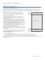
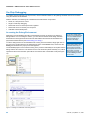
Memory space is broken into three main areas, as illustrated in Figure 4. Memory and peripheral I/O devices placed and wired
within the FPGA design are mapped into this space. Further information can be found in the section – Division of Memory
Space.
Before detailing the nature of each of these memory regions, it is
worthwhile discussing the difficulties with mapping devices into this
memory, and the solution that Altium Designer brings to the problem.
FFFF_FFFFh
Peripheral I/O
FF00_0000h
FEFF_FFFFh
Defining the Memory Map
An area that can be difficult to manage in an embedded software
development project is the mapping of memory and peripherals into the
processor’s address space.
The memory map, as it is often called, is essentially the bridge between
the hardware and software projects – the hardware team allocating each
of the various memory and peripheral devices their own chunk of the
processor’s address space, the software team then writing their code to
access the memory and peripherals at the given locations.
External Memory
To help manage the process of allocating devices into the space there are
a number of features available to both the hardware designer and the
embedded software developer in Altium Designer.
This discussion is based around the PPC405CR processor, however the
overall approach can be applied to any of the 32-bit processors available
in Altium Designer.
0100_0000h
00FF_FFFFh
Building the Bridge between the Hardware and Software
Defining the memory map on the hardware (FPGA project) side is
essentially a 3 stage process:
Internal Memory
0000_0000h
Figure 4. Memory organization in the PPC405CR
•
Place the peripheral or memory
•
Define its addressing requirements (this is most easily done using a Wishbone Interconnect device)
•
Bring that definition into the processor’s configuration, which can then be accessed by the embedded tools
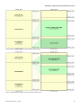
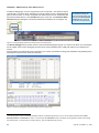
Figures 5 and 6 show examples of memory and peripheral devices mapped into the addressable memory and IO ranges for the
PPC405CR respectively.
10
CR0161 (v2.0) March 11, 2008