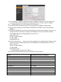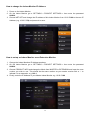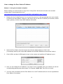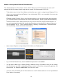
1
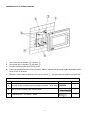
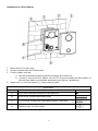
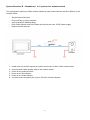
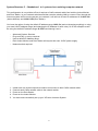
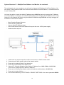
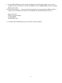
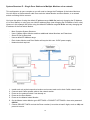
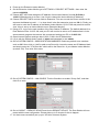
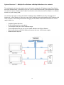
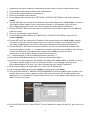
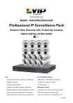
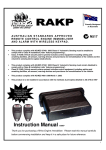
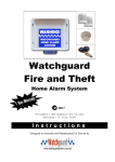
www.rhinoco.com.au MODEL: INTIPRKIT Residential IP Intercom Kit Includes Door station and Indoor Monitor ‘QUICK INSTALLATION GUIDE’ N517 Indoor Monitor Door Station - Advanced H.264 Video Compression Technology - Advanced H.264 Video Compression Technology - Easy to operate touch screen - High Quality 1.3MP CMOS Image sensor - 10/100Mbps Ethernet - 10/100Mbps Ethernet - Info publish, leave message, emergency calling - Unlock Door Remotely - 4Gb Internal Storage - Built-in loudspeaker - 12v DC - 12v DC V2.0 040314 2 Package Contents (Before installation, please ensure you have all the parts listed below). 1 x Indoor Monitor INTIPMONB ● Advanced H.264 Video Compression Technology for High Quality Images ● Easy to Operate ● Touch Screen ● 4Gb Internal Storage (non-removable SD Card) ● 12v DC 1 x Door Station INTIPRDSV ● 1.3MP HD Image ● Easy to Operate ● Loudspeaker ● Door Release Output ● 12v DC 1 x 86 Box for Door Station ● Assist with mounting the INTIPRDSV Door Station to concrete or brick environments 1 x Cat5e Ethernet Cable ● Pre-terminated - Allowing Simple Plug-in Connection ● 30m Ethernet Cable 2 x Switch Mode Power Supplies ● 2 x 12v DC Power Supplies for use with the Monitor and Door Station 3 Installation of an Indoor monitor 1. Use screw b to fix bracket ② onto box ④. 2. 3. Use screw a to fix bracket ② onto wall ③. Connect network cable and 12vDC power 4. Face rear installation slot to slot on bracket. Make it against wall and push lightly downward until it fits in to slot on bracket. Remove: Insert small screwdriver into hole on device ①, and push device upward until removed. 5. Screw Illustration No. Name Illustration a ST3×18 Cross recessed pan head tapping screws - white alloy 3 b M4×30 Cross recessed pan head screws 2 c Expansion pipe ¢6*30mm white 3 4 Quantity Installation of a Door Station 1. 2. 3. 4. Mount 86 box in to wall cavity. Connect network cable and 12vDC power Fix Door Station onto wall: a. Use the included M4 screws to attach Door Station onto the 86 box. b. In order to secure the Door Station, use the ST3.0 screw included with Door Station to affix the Door Station onto wall after attachment to the 86 box. (as b Above). Attach cover ① onto Door Station ②, using screws a to affix. No. Screw Note Name a M3×8 Cross recessed countersunk head-black zinc b M4×30 Cross recessed pan head screws c ST3×18 Cross recessed pan head tapping screws –white alloy d Expansion pipe ¢6*30mm white 5 Illustration Intercom System Configuration The process to set up your Intercom system may vary depending upon your system structure. Please see the following examples of system structures and follow the process which best meets your requirements. System Structure A – Standalone 1 to 1 by direct connection This configuration has only 1 of each unit and requires a single Cat5e network cable to run directly from the Indoor Monitor to the Door Station. System Structure B – Standalone 1 to 1 system via a network switch This configuration has only 1 of each unit and requires a Cat5e network cable from each Indoor Monitor and Door Station, to the network switch. System Structure C – Standalone 1 to 1 system via an existing computer network This configuration still has only 1 of each unit but has a Cat5e network cable from both the Indoor Monitor and Door Station, to your network switches and then uses the existing LAN to connect. Even through the Intercom system will be running across your network, it will still use its Default IP address range. System Structure D – Multiple Door Stations to a Monitor via a network This configuration is more complex as you can use 2 or more Door Stations with an Indoor Monitor but you will need to change some IP addresses. You will require a Cat5e network cable from each the Indoor Monitor and Door Station, to a network switch or to your existing LAN. System Structure E – Single Door Stations to Multiple Monitors via a network This configuration is more complex as you can use your Door Stations with 2 or more Indoor Monitors but you will need to change some IP addresses. You will require a Cat5e network cable from each the Indoor Monitor and Door Station, to a network switch or existing LAN to connect. System Structure F – Multiple Door Stations to Multiple Monitors via a network This configuration is the most complex as you will need to change the IP address of each Door Station and each Indoor Monitor. It will allow you to use up to 6 Indoor Monitors and 6 Door Stations together. You will also require a Cat5e network cable from each the Indoor Monitor and Door Station, to a network switch or to your existing LAN. The User Password is 123456 which may be used for basic operation of the Intercom System. The Project Password 002236 is required only for configuration and set up of additional devices. The Door stations own web interface of will require the Username admin and a Password of admin. 6 System Structure A – Standalone 1 to 1 by direct connection This configuration requires only a single Cat5e network cable to run directly from the Indoor Monitor to the Door Station. - Very Simple System Structure Plug and Play, no set up required. Uses a default IP Address range. Each Indoor Monitor and Door Station will require their own 12vDC power supply. 1. 2. 3. 4. Install each unit at their respective location and connect to the shared Cat5e network cable. Power on the Door Station Power on the Indoor Monitor You have now successfully set up your VIPvision Intercom System. 7 System Structure B – Standalone 1 to 1 system via a network switch This configuration requires a Cat5e network cable from each Indoor Monitor and Door Station, to the network switch. - Simple System Structure Plug and Play, no set up required. Uses a default IP Address range. Each Indoor Monitor and Door Station will require their own 12vDC power supply. Network switch required. 1. 2. 3. 4. 5. 6. Install each unit at their respective location and connect to their Cat5e network cable. Connect each Cat5e network cable to the network switch. Power on the network Switch Power on the Door Station Power on the Indoor Monitor You have now successfully set up your VIPvision Intercom System. 8 System Structure C – Standalone 1 to 1 system via an existing computer network This configuration is very similar to B as it requires a Cat5e network cable from both the Indoor Monitor and Door Station, to your network switches and then uses the existing LAN to connect. Even through the Intercom system will be running across your network, it will still use its own IP addresses of 10.22.5.180 (Indoor Monitor) and 10.22.5.189 (Door Station). You have the option of using the default IP address range 10.22.5.x (and not changing anything) or using your own LAN IP address range (and changing the IP Address of each units). So in this example we will be using the default IP address range 10.22.5.x and leaving it as is. - Advanced System Structure Plug and Play, no set up required. Uses a default IP Address range. Each Indoor Monitor and Door Station will require their own 12vDC power supply. Network switch required. 1. 2. 3. 4. 5. Install each unit at their respective location and connect to their Cat5e network cable. Connect each Cat5e network cable to the network switch. Power on the Door Station Power on the Indoor Monitor You have now successfully set up your VIPvision Intercom System. 9 System Structure D – Multiple Door Stations to a Monitor via a network This configuration is more complex as you will need to change the IP address of the Door Stations. You will require a Cat5e network cable from each the Indoor Monitor and Door Station, to a network switch or to your existing LAN. You have the option of using the default IP address range 10.22.5.x (and only changing the IP Address of 1x Door Station) or using your own LAN IP address range (and changing the IP Address of all 3 units). However in this example we will be using the default IP address range 10.22.5.x and only changing the IP address of the first Door Station. - More Complex System Structure Some IP Set Up Required. Uses a default IP Address range. Each Indoor Monitor and Door Station will require their own 12vDC power supply. Network switch required. 1. 2. 3. 4. 5. Install each unit at their respective location and connect to Cat5e network cable. Connect each Cat5e network cable to the network switch. Power on the network Switch if not already on. Power on the Secondary Door Station First Using a PC, find and change the Door Station IP Address from 10.22.5.189 to 10.22.5.190 (see “How to change the Door Station IP Address”). 6. Power on the Primary Door Station (which will keeps its default address 10.22.5.189) 7. Power on the Indoor Monitor 8. On the Indoor Monitor go to SETTINGS > PROJECT SETTINGS > then enter password 002236 10 9. Choose NETWORK and you will see the settings for the Primary Door Station. Here you can change the name of the device, check the IP Address is set to 10.22.5.189 and ensure its Enable Status is set to ON. 10. Press the Next Arrow “ > ” and you will see the settings for the secondary Door Station. Enter a name for your secondary door station, the IP Address and set Enable Status to ON. e.g. Name: Sub VTO Device: Unit Door Station IP: 10.22.5.190 Enable Status: ON 11. You have now successfully set up your VIPvision Intercom System. 11 System Structure E – Single Door Stations to Multiple Monitors via a network This configuration is more complex as you will need to change the IP address of the Indoor Monitors. You will require a Cat5e network cable from each the Indoor Monitor and Door Station, to a network switch or existing LAN to connect. You have the option of using the default IP address range 10.22.5.x (and only changing the IP Address of 1x Door Station) or using your own LAN IP address range (and changing the IP Address of all 3 units). However in this example we will be using the default IP address range 10.22.5.x and only changing the IP address of the first Indoor Monitor. - More Complex System Structure. Uses 1 Master Indoor Monitor and then additional Indoor Monitors are Extensions. Some IP Set Up Required. Uses a default IP Address range. Each Indoor Monitor and Door Station will require their own 12vDC power supply. Network switch required. 1. 2. 3. 4. 5. 6. Install each unit at their respective location and connect each unit to their Cat5e network cable. Connect each Cat5e network cable to the network switch. Power on the network Switch if not already on. Power on the Door Station. Power on the Master Indoor Monitor. On the Master Indoor Monitor go to SETTINGS > PROJECT SETTINGS > then enter password 002236 7. Choose PROJECT INFO and set the Room number (it must be at least 3 digits, such as 102) and press ok to save. 12 8. Power on the Extension Indoor Monitor. 9. On the Extension Indoor Monitor go to SETTINGS > PROJECT SETTINGS > then enter the password 002236 12. Choose NET INFO and change the IP address of this Indoor Monitor from 10.22.5.180 to 10.22.5.179 and press ok to save. (see “How to change the Indoor Monitor IP Address”). 10. Choose PROJECT INFO and set mode to Extension. You can now set the Room number to the same as the Master but add “ -1 “ to show that it is the first extension (such as 102-1). Finally you will have to enter the IP address of the Master Indoor Monitor 10.22.5.180 and press ok to save. (see “How to set up an Indoor Monitor as an Extension Monitor”). 11. Using a PC, log in to the web interface of the Door Station IP Address. The default address for a Door Station will be 10.22.5.189, and your PC will need to be set to an IP address that is in the same network range as the camera. We recommend setting your PC to 10.22.5.100 12. Open Internet Explorer and type http://10.22.5.189 in the IE address bar. 13. Log in with the Default factory name of admin and password is also admin. 14. Go to SYSTEM CONFIG > INDOOR STATION MANAGER. Delete any default room numbers such as 9901 then click on “Add” to add a new Room No. Leave the name and IP Address blank and simply enter the “VTH Short No” which will be the Room No. of your Master Indoor Monitor. (such as 102). Then click Ok to save. 15. Go to SYSTEM CONFIG > LAN CONFIG. Tick the Checkbox to enable “Group Call”, and then click Ok to save. 16. Go to LOGOUT > REBOOT DEVICE and click to REBOOT DEVICE. The Door Station will now restart with the new configuration. Please allow up to 5 minutes for this to happen. 17. You have now successfully set up your VIPvision Intercom System. 13 System Structure F – Multiple Door Stations to Multiple Monitors via a network This configuration is the most complex as you will need to change the IP address of each Door Station and each Indoor Monitor. It will allow you to use up to 6 Indoor Monitors and 6 Door Stations all together. You will also require a Cat5e network cable from each the Indoor Monitor and Door Station, to a network switch or to your existing LAN. You will have the option of using the default IP address range 10.22.5.x (and only changing the IP Address of 1x Door Station) or using your own LAN IP address range (and changing the IP Address of all units). However in this example we will be changing the IP address of all devices to match our own IP range of 10.1.1.x - Complex System Structure. IP Set Up Required for every device. This example uses your own IP Address range. This configuration can give you up to 6 Indoor Monitors and 6 Door Stations. Each Indoor Monitor and Door Station will require their own 12vDC power supply. Network switch required. 14 1. 2. 3. 4. 5. Install each unit at their respective location and connect each unit to their Cat5e network cable. Connect each Cat5e network cable to the network switch. Power on the network Switch if not already on. Power on the Master Indoor Monitor. On the Master Indoor Monitor go to SETTINGS > PROJECT SETTINGS > then enter password 002236 6. Choose NET INFO and change the IP address of this Indoor Monitor from 10.22.5.180 to one that is in the same network range as your own computer network, in this example we will be using 10.1.1.180 and press ok to save. (see “How to change the Indoor Monitor IP Address”). 7. Choose PROJECT INFO and set the Room number (it must be at least 3 digits, such as 102) and press ok to save. 8. Power on the Extension Indoor Monitor. 9. On the Extension Indoor Monitor go to SETTINGS > PROJECT SETTINGS > then enter the password 002236 10. Choose NET INFO and change the IP address of this Indoor Monitor from 10.22.5.180 to another one that is in the same network range as your own computer network, in this example we will be using 10.1.1.179 and press ok to save. (see “How to change the Indoor Monitor IP Address”). 11. Choose PROJECT INFO and set mode to Extension. You can now set the Room number to the same as the Master but add “ -1 “ to show that it is the first extension (such as 102-1). You will have to enter the IP address of the Master Indoor Monitor 10.1.1.180 and press ok to save. (see “How to set up an Indoor Monitor as an Extension Monitor”). 12. ----- Repeat Steps 8–11 for any additional Extension Monitors ----13. Now that all Indoor Monitors are set up, Power on the first Door Station. 14. Using a PC, find and change the Door Station IP Address from 10.22.5.189 to to another one that is in the same network range as your own computer network, in this example we will be using 10.1.1.190 and press ok to save. (see “How to change the Door Station IP Address”). 15. Open Internet Explorer and type http://10.1.1.190 in the IE address bar. 16. Log in with the Default factory name of admin and password is also admin. 17. Go to SYSTEM CONFIG > INDOOR STATION MANAGER. Delete any default room numbers such as 9901 then click on “Add” to add a new Room No. Leave the name and IP Address blank and simply enter the “VTH Short No” which will be the Room No. of your Master Indoor Monitor (such as 102). Then click Ok to save. 18. Go to SYSTEM CONFIG > LAN CONFIG. Tick the Checkbox to enable “Group Call”, then click Ok to save. 15 19. Go to LOGOUT > REBOOT DEVICE and click to REBOOT DEVICE. The Door Station will now restart with the new configuration. Please allow up to 5 minutes for this to happen. 20. ----- Repeat Steps 13–19 for any additional Door Stations ----21. Now that all Door Stations are set up, we can go back to the Master Indoor Monitor 22. On the Indoor Monitor go to SETTINGS > PROJECT SETTINGS > then enter password 002236 23. Choose NETWORK and you will see the settings for the Primary Door Station. Here you can change the name of the device, change the IP Address to that of your first Door Station 10.1.1.189 and ensure its Enable Status is set to ON. e.g. Name: Main VTO Device: Unit Door Station IP: 10.1.1.189 Enable Status: ON 24. Press the Next Arrow “ > ” and you will see the settings for the additional Door Stations. Enter a name for your secondary door station, the IP Address and set Enable Status to ON. e.g. Name: Sub VTO Device: Unit Door Station IP: 10.1.1.190 Enable Status: ON ----- Repeat Step 24 for each Door Station ----25. You have now successfully set up your VIPvision Intercom System. Device: IP Addresses (used in our example): Master Indoor Monitor 102 10.1.1.180 Extension Indoor Monitor 102-1 10.1.1.179 Extension Indoor Monitor 102-2 10.1.1.178 Extension Indoor Monitor 102-3 10.1.1.176 Extension Indoor Monitor 102-4 10.1.1.175 Extension Indoor Monitor 102-5 10.1.1.174 Door Station 1 10.1.1.189 Door Station 2 10.1.1.190 Door Station 3 10.1.1.191 Door Station 4 10.1.1.192 Door Station 5 10.1.1.193 Door Station 6 10.1.1.194 16 How to change the Indoor Monitor IP Address 1. Power on the Indoor Monitor 2. On the Indoor Monitor go to SETTINGS > PROJECT SETTINGS > then enter the password 002236 3. Choose NET SET and change the IP address of this Indoor Monitor from 10.22.5.180 to the new IP Address (e.g. 10.22.5.179) and press ok to save. How to set up an Indoor Monitor as an Extension Monitor 1. Change the Indoor Monitors IP Address as above. 2. On the Indoor Monitor go to SETTINGS > PROJECT SETTINGS > then enter the password 002236 3. Choose PRODUCT INFO and change the Mode from MASTER to EXTENSION and input the room number you wish to use. This should be the same number as your master monitor with a “-“ to indicate it is an extension. e.g. 102-1 4. Finally, enter the IP Address of your Master Indoor Monitor e.g. 10.22.5.180 17 How to change the Door Station IP Address Method 1 - Using the included ConfigTool Before starting you must first have a copy of the “Config Tools” which can be found on the included software disc or downloaded from here: http://downloads.rhinoco.com.au/dvr/VSIP1MPFBIR_VSIP1MPDIR_Scan_Tool.zip 1. Double click the “ConfigTools.exe” icon to open the scan tool. It will automatically scan your network to find the new Door Station, and then in the device list you will see IP address, port number, subnet mask, gateway, and the unique MAC address information. 2. Select the Door Station from the list as it should be the default address 10.22.5.189 (if necessary match up the unique MAC address with the MAC Address on the devices’ sticker). 3. Click LOGIN, and then LOGIN again to log in to the camera and modify the IP address to your 4. Here you can change the IP address to one that is more compatible with your network, as well the corresponding gateway and subnet mask. For Example 10.22.5.190. Then Click ok to save. 5. You have now successfully set the Door Station to a new IP Address and can now set up additional Door Stations if necessary. 18 Method 2 - Using Internet Explorer (Recommended) The default address for a Door Station will be 10.22.5.189, and your PC will need to be set to an IP address that is in the same network range as the camera. We recommend 10.22.5.100 - To be able to log in to the Door Station web interface you must be using Internet Explorer 5.5 or above, we recommend Internet Explorer 9 as unfortunately IE10 is not compatible. You must also have ActiveX Controls. Enabling ActiveX Controls: If this is your first time logging in, you may get a system pops up asking you to install ActiveX control webrec.cab. Please click OK button, and the system will automatically install the ActiveX control. When finished you may need to close and re-open Internet Explorer. If you can’t download the ActiveX file, please check whether you have ActiveX is allowed under your Security Settings. Go to: Tools > Internet Options > Security > Custom Level > Then once in the Security Settings, enable all ActiveX related options. - Open Internet Explorer and input http://10.22.5.189 in the IE address bar. - Log in with the Default factory name of admin and password is also admin. - You will then be able to go to System Config > Network Config > IP Address. Here you can change the IP address to one that is compatible with your network, as well the corresponding gateway and subnet mask. For Example 10.22.5.190. Then Click ok to save. - You have now successfully set the Door Station to a new IP Address and can now set up additional Door Stations if necessary. 19 Set the Time and Date When using your Intercom system you may need to set the correct Time and Date. The Indoor Monitor takes its Time and Date from the Door Station itself. Should you also have an NVR connecting to your Door Stations, then the Door Stations will take their Time and Date from the NVR. When using an NVR with your Intercom System: 1. Go to your NVR that is displaying the Door Stations Cameras. 2. Right clicking anywhere on the screen will bring up the password menu. 3. Use the mouse to enter the NVR admin password with the on-screen keypad. 4. Then Right click to open the menu and select “MAIN MENU”. 5. Select “SETTING” 6. Select “GENERAL” 7. Set System Time, Date Format and DST (Daylight Saving Time) for your region. If you do not have an NVR: 1. You will need to have a PC (in the same IP range) that is capable of connecting to the Web Interface of the Door Station. 2. Open Internet Explorer and input the Door Station IP Address in to the IE address bar. e.g. http://10.22.5.189 3. Log in with the Default username name of admin and password is also admin. 4. You will then be able to go to System Config > Local Config > System Time. Here you can change the Time and Date format and Sync the Door Station to your PC time. 20 Using a PC to find available IP Addresses Before setting up your Intercoms you will first need to find it an IP address. This process is to help you find what IP Addresses are currently in use on your computer network, and in turn which ones are still available. If you are not connecting the Intercoms to a computer network (or internet connection) then any default IP address range may be used. e.g.192.168.0.100 to 192.168.0.130. Before starting you must first have a copy of the “Free IP Scanner” Tool which can be downloaded here: http://downloads.rhinoco.com.au/dvr/Free_IP_Scanner.zip 1. Open the Free IP Scanner Tool (if it asks for registration just press skip as it is free to use). 2. Begin the scan by clicking on 3. The “Free IP Scanner” will automatically detect all IP Addresses on your Computer network and display which ones are in use by listing with a Green tick beside them. Those which have a red cross beside them are not currently in use and may be available. Note: Even though lower numbered address may be free (such as “?.?.?.8”) we recommend using higher number which are unlikely to be used in the immediate future such as “?.?.?.100” onwards. 4. If you wish to Export the list, you can do this by going to FILE and choosing EXPORT. It can then be saved as text file and even emailed. 21 How to connect to an IP Camera from the Indoor Monitor In order to connect to an IP Camera from the Indoor Monitor, both the Intercom system and the IP camera will need to be connected to the same computer network and use the same IP Address range. If using a NVR system with a built in (Plug & Play) POE switch, the intercom will not be able to connect to the individual IP Cameras. You will need to change the IP Camera over to the local network with local IP Addresses. Please see your NVR User Guide to do this. 1. 2. To add the IP Camera in to the Indoor Monitor, Go to Settings > IPC Info Enter a Name, IP Address and the Default factory user name of admin and password of admin. The Indoor Monitor can only connect to the IP Cameras Extra Stream when set to D1 resolution. This is thanks to the monitor itself only being capable of displaying a D1 image. In order to configure the IP cameras Extra Stream you will first need to log in to its web interface. To do this: 1. 2. Type the IP Cameras IP Address in to Internet Explorer (providing you have already found its IP address). e.g. http://10.1.1.108 Go to SETUP > CAMERA > VIDEO and make sure you set the Extra Stream resolution to D1(704*576). The Watermark can also be turned off. 22 How to wire an Electric Door Strike to the Door Station Most Electric Door Strikes will unlock when powered and lock when they are without power. This means the negative from 12v Power Supply output can simply be looped through the Door station and connected to the Electric Door Strike. The power supply’s positive output would then connect directly to the electric lock. When connecting the Door Station to an Electric Door Strike: - The Electric Door Strike positive (+) is connected to the 12vDc Power supply positive (+). - The Electric Door Strike negative (-) is connected Door Stations COM terminal. - The 12vDc Power supply negative (-) is connected to the Door Stations NO terminal. When connecting the Door Station to the optional Unlock Button: - Make sure the passive unlock button connects to Door Station ALM 2 and GND. 23 How to take Videos / Snapshots on the Indoor Monitor During a call you can also take a video from the Door Stations camera by pressing this will record audio and video which will then be stored in the Indoor Monitors internal storage. During a call you can take a snapshot from the Door Stations camera by pressing this image will then be stored in the Indoor Monitors internal storage. You can also Auto Capture Snapshots when someone rings the Door Station. On the Indoor Monitor go to SETTINGS and set AUTOCAPTURE to “On” How to view your Videos / Snapshots on the Indoor Monitor On the Indoor Monitor go to MESSAGE > VIDEOS PICTURES Choose the one you wish to see and Press “View”. 24 Troubleshooting Please refer to the FAQ table below for easy troubleshooting. The table below describes some typical problems and their solutions. Please consult these guides before contacting your Intercom dealer. PROBLEM No power No live video Cannot connect to one device when it has been programmed. Door Station and Monitors not connecting SOLUTION - Check power cord connection. - Confirm that there is power from the outlet. - Ensure that the 12V PSU is connected to each unit. - Check the cameras cable and connections. - Check the monitors cable and connections. - Ensure you are not in playback mode. - Try to ping its IP address from a PC. - Reboot All Devices and Wait 5 minutes to ensure all devices have finished loading. - Test the Network cables with a Lan Cable Tester This guide is intended as a Quick Set Up and Basic use manual only, please refer to the User Manual on the included CD for all other details. 25 Limited Warranty Cornick Pty Ltd (Seller) warrants its products to be in conformance with its own plans and specifications and to be free from defects in materials and workmanship under normal use and service for forty eight months from the date of original purchase. Sellers obligation shall be limited to repairing or replacing, at its option, free of charge for materials or labor, any part which is proved not in compliance with Sellers specifications or proves defective in materials or workmanship under normal use and service. Seller shall have no obligation under this Limited Warranty or otherwise if the product is altered or improperly repaired or serviced by anyone other than Seller. For Warranty Service: Return transportation prepaid with a copy of your purchase receipt and contact details to: RhinoCo Technology, 9 Hannabus Place, McGraths Hill, NSW 2756 Australia. Seller has no obligation to attend the buyer’s location to retrieve the goods or make repairs onsite. There are no warranties, expressed or implied, of merchant ability, or fitness for a particular purpose or otherwise, which extend beyond the description on the face hereof. In no case shall seller be liable to anyone for any consequential or incidental damages for breach of this or any other warranty, express or implied, or upon any other basis of liability whatsoever, even the loss or damage is caused by its own negligence or fault. Seller does not represent that the products it sells may not be compromised or circumvented; that the products will prevent any personal injury or property loss by burglary, robbery, fire or otherwise; or that the products will in all cases provide adequate warning or protection. Customer understands that a properly installed and maintained alarm system or video surveillance system may only reduce the risk of a burglary, robbery, or fire without warning, but it is not insurance or a guarantee that such will not occur or that there will be no personal injury or property loss as a result. Consequently, seller shall have no liability for any personal injury; property damage or other loss based on a claim the product failed to give any warning. However, if seller is held liable, whether directly or indirectly, for any loss or damage arising under this limited warranty or otherwise, regard less of cause or origin, seller's maximum liability shall not in any case exceed the purchase price of the product, which shall be the complete and exclusive remedy against seller. This warranty replaces any previous warranties and is the only warranty made by the Seller on this product. No increase or alteration, written or verbal, of the obligations of this Limited Warranty is authorized. Please refer to the website (www. watchguardalarms.com.au) for a full list of trading terms. 26 PLEASE CUT OUT & RETURN THIS INFORMATION WITHIN 14 DAYS OF PURCHASE TO: RhinoCo Technology 9 Hannabus Place McGraths Hill NSW 2756 Australia Model: INTIPRKIT Professional Surveillance Pack Warranty Card Name Address Suburb State Postcode Email Date of Purchase Invoice Number Daytime Phone Where did you purchase your INTIPRKIT? Store Location This information will only be used by the manufacturer and will not be sold to any third parties. Dear Customer, We appreciate your confidence in our product, and you can be certain that we will do everything possible to ensure that you are happy with your decision and that you have years of satisfaction from your INTIPRKIT. We take extreme care in the research, design and development of our products to ensure they meet your needs. Additionally, we keep in close contact with our dealers Australia wide, and should any problem occur, we will work closely with your local dealer to see that it is resolved quickly. As a leading designer and manufacturer, we are continually endeavoring to exceed the expectations of our customers. Furthermore, we appreciate your input regarding potential design improvements, issues regarding our service and support, and any other ideas you may have which could help us to serve you better. Please make any comments you have here: 27