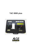
1
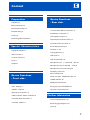
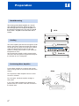
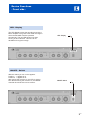
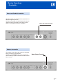
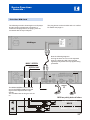
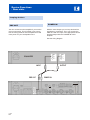
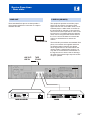
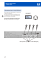
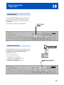
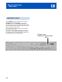
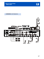
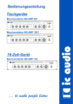
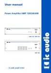
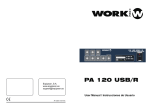
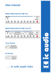
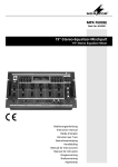
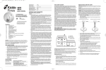
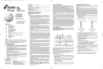
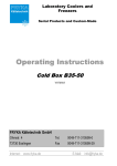
User manual
Desktop
MIXER AMPLIFIER MX-AMP 60T
MX-AMP 60T MIXER AMPLIFIER
MIXER AMPLIFIER MX-AMP 120T
19-inch-rack mounting
MIXER AMPLIFIER MX-AMP 120
MX-AMP 120 MIXER AMPLIFIER
… to make people listen
ic audio
MX-AMP 120T MIXER AMPLIFIER
Status 02/2006
MX-AMP 60 / MX-AMP 120
ic audio
Mixer-Amplifier - Front MX-AMP 60 MIXER AMPLIFIER
MX-AMP 120 MIXER AMPLIFIER
600
Mixer Amplifier
80000048
120 W
115/230V~50-60Hz
PHANTOM
LINE
MIC
CHIME
Made by ic audio
Serial No.
1V 8
ON
DC 24V
+
COM
8
100V
SPEECH ONLY
COM
PRE OUT
0
~
PRIORITY
TEL/EMER
AUX
CD
100V
POWER IN
EN
~
OFF
LINE FUSE
2
P
PHANTOM
LINE
MIC
MONITOR OUTPUT
MUSIC/SPEECH
+
1W
POWER INPUT:350WATTS
TAPE OUT
LINE IN
MIC 4
MIC 3
SENS VR
SENS VR
MIC 2
MIC 1
PRIORITY
DC 24V
INPUT
-
MX-AMP 120
Art. No.
Rated Output Power
Supply Voltage
GND
230V~
+
115V~
Apparatus delivered
Connected for 230v~
CHIME
Mixer-Amplifier - Rear -
Content
Preperation
Unpacking 5
ic audio
Device Functions
- Rear side -
Safety Instructions 5
General Informations 5
115V and 230V Mains Connection 13
Rack-Mounting 6
24V Battery Connection 13
Cooling 6
100V Speaker Output 14
Positioning Mixer Amplifier 6
Disjoined Anouncement Zones 14
Connection with One Zone 15
Special Characteristics
Paging Microphone 7
Alarm Function 7
Common Function 7
Inputs 7
Outputs 7
6-Pole Microphone Input
Priorities 17--20
Looping Devices 21
LINE OUT 22
LINE IN (AUX/CD ) 23
Microphone input 1 - 4 with XLR - Jack 24
Microphone input1-4 with DIN - Jack 25
Microphone input 4-pole clamp 26
Sensitivity Control for
MIC1 und MIC2 26
Device Functions
- Front side -
Switch for LINE - PHANTOM - MIC 25
CHIME ON/OFF 26
MONITOR OUTPUT 26
LED - Display 9
Emergency Input TEL/EMER 27
ON/OFF -Switch 9
Top view of all functions 28
Microphone Controller 10
LINE-Controller, Switch AUX/CD 10
Controller Bass and Treble 11
Controller Master 11
Further Information
Technical Specifications 30
Block Plugging Diagramm 31
Index 32
EN
3
Preparation
ic audio
Unpacking
Please note the unpacking instructions
- Unpacking
- Safety Instructions
- General Informations
Safety Informations
Please note the safety instructions before the
connecting the MX-AMP 60 and MX-AMP 120
- Rack-Mounting
- Cooling
- Positioning Mixer Amplifier
General Informations
Cooling and instructions for the installation
Rack-Mounting
Informations about the right rack-mounting
Cooling
Please note the ventilation - cooling
guidelines
Positioning Mixer Ampifier
Please note the positioning
of the Mixer - Amplifier
EN
4
Preparation
ic audio
General Informations
Unpacking
Please verify if the following parts were delivered:
!
line cord
!
mounting foots pre-assembled
! DO NOT run microphone cables near mains,
data, telephone or 100V line cables.
! DO NOT run 100V line cables near data,
telephone or other low voltage cables.
! DO NOT exceed 90% of the amplifiers output
power when using 100V line (speech only).
! DO NOT exceed 70% of the amplifiers output
power when using 100V line (high level
background music).
! DO NOT use re-entrant horn loudspeakers for
background music unless the loudspeaker has
been specifically designed for this purpose.
!
!
!
Safety instructions
!
!
The wires of the main power line have the following
colours:
GREEN and YELLOW:
(E)
BLUE:
(N)
BROWN :
(L)
AVOID jointing the microphone cable, when
this is unavoidable make sure a good screened
connector is used, e.g. XLR.
ALWAYS use a balanced or floating low
impedance microphone terminating into a
balanced input on long microphone cable runs.
ALWAYS use a mains grade double insulated
cable for the loudspeaker cable runs.
ENSURE that all loudspeakers are in-phase.
ENSURE that there are no short circuits on the
loudspeaker line before connecting to the
amplifier.
As the colours of the wires in the mains lead of this
apparatus may not correspond with the coloured
markings identifying the terminals in your plug
proceed as follows:
The wire which is coloured green and yellow must
be connected to the terminal which is marked by
the letter E or by the safety earth symbol or
coloured green and yellow. The wire which is
coloured blue must be connected to the terminal
which is marked with the letter N or coloured
black. The wire which is coloured brown must be
connected to the terminal which is marked with the
letter L or coloured red.
If a 13 Amp (B.S.1363) plug or any other type of
plug is used,a 5 Amp fuse must be fitted either in
the plug or at the distribution board.
5
EN
Preparation
ic audio
Rack-Mounting
The housing of the Mixer-Amplifier is a 19 inch
rack standard construction. Please check if you
have enough space for cooling the amplifier. For
the optimum mounting in the 19” rack you should
fix the mixer - amplifier in the rack-frame with 4
screws.
40°C
POWER
EJECT
AUTOREVERSE
Background Music Casette Player
PROGRAM
Cooling
Exhaust air
The mixer amplifer pulls fresh air through the small
holes in the bottom sheet and pushes the exhaust
air through the long holes in the top sheet. Please
make sure that the internal space of the rack
system is cooling and you have a room maximum
temperature of 40°C..
We recommend to install a cooling system at the
rear site of the racksystem to support the transport
the exhaust air in the racksystem.
MX-AMP120 MIXER AMPLIFIER
Fresh air
Positioning Mixer Amplifier
Put the Mixer Amplifier in a position with enough
space enough fresh air to minimise the heat in the
system.
Do not place the Mixer Amplifier close to of heat
sources or a heater.
Do not expose the Mixer Amplifier sunlight or
heavy dust.
If you use the Mixer Amplifier as a tabletop unit
please make sure that the 4 feet are mounted on
the bottom side.
EN
6
false
Special Characteristics
ic audio
Paging Microphone Functions
- Paging Microphone Functions
!
!
!
4 Microphone inputs with different Priorities
Pre-chime hook up
Sensitivity Control for Microphones
- Alarm Function
- Common Function
- Inputs
- Outputs
Alarmfunctions
!
!
!
2 split Output zones
Music muting
Pre-Amplifier Output
Common Function
!
!
!
115V and 230V Mains Connection
24V Battery Connection
Monitor Output
Inputs
!
!
!
!
CD
AUX
PRE-AMP
Telephone/Emergency Connection
Outputs
!
!
!
!
!
!
!
100V 8ohm 8ohm 100V TAPE
LINE
PRE-AMP
Speaker of the first Zone
Speaker of the first Zone
For Monitor speaker
Speaker of the second Zone
7
EN
Device Functions
- Front side -
ic audio
LED - Display
Display for the activation
- LED - Display
- ON/OFF - Switch
- Microphone Controller
- LINE - Controller,
Switch AUX/CD
- Bass and Treble Controller
- Master Controller
ON/OFF - Switch
Setting - up the Mixer-Amplifier
Microphone Controller
Controller for the Microphone volume
LINE-Controller, Switch AUX/CD
Volume Control of the acoustic signal source
Bass and Treble Controller
Control of the high and deep frequency
Master Controller
Control of all Signals
EN
8
Device Functions
- Front side -
ic audio
LED - Display
The LED-Display shows the recording level of the
Mixer-Amplifier. The green LEDs show the range in
which the MX-AMP could be operated
permanently. The red LED shines only when
running in full conduction. This zone is not
advisable for long-term usage.
LED - Display
ON/OFF - Switch
With this switch you turn on the apparat.
Position I = apparat is on
Position 0 = apparat is off
After turning the machine on, the LED is shining
blue. Before turning the machine on, the Master
controller should be set to a low volume.
ON/OFF -Switch
9
EN
Device Functions
- Front side -
Microhpone Controller
ic audio
Microphone Controller
With the Microphone Controller you can controll
the volume of the separate microphones.
LINE - Controller, Switch AUX/CD
With the LINE - Controller you can controll the
volume of the connected signal source.
The source can be a CD-Player or a cassette
recorder.
You can change the function of AUX/CD with the
switch between the LINE and the BASS controller.
EN
10
LINE - Controller
Device Functions
- Frontside -
ic audio
Bass and Treble Controller
With this control you can adjust the reproduction of
deep and high frequencies.
The bass control lifts or lowers frequencies near to
100Hz at 10dB. The treble-control has the same
effect on at frequencies near to 10.000Hz.
Bass and Treble Controller
Master Controller
The master control drives the volume of all signals
being processed by the amplifier.
Signals of the TEL/EMERgency input excepted are.
This is made by a poti on the back side and cannot
be set to zero.
Master Volume Controller
EN
11
Device Functions
- Rearside -
ic audio
115V and 230V Mains Connection
Selector to adapt the mains connection
24V Battery Supply
Connection to ups
100V/8ohm Speaker Output
Terminal for 100V/8ohm - speakers
- 115V and 230V Mains Connection
- 24V Battery Connection
Disjoined Anouncement Zones
Driving different zones in priority settings.
Connection with One Zone
- 100V Speaker Output
- Disjoined Anouncement Zones
- Connection with One Zone
Driving only one zone
6-pole Microphone Input
Connection for max. 12 Microphones
Priorities
- 6-pole Microphone Input
- Priorities
- Looping Devices
- TAPE OUT / LINE IN
- LINE IN (CD/AUX)
- Microphone input 1-4 wit XLR-Jack
- Microphone input 1-4 wit DIN-Jack
Effects of different priority statuses
Looping Devices
Connection to and from an other device
TAPE OUT / LINE OUT
Terminal for LINE OUT
LINE IN (CD/AUX)
Terminal for Line IN devices
Microphone input 1-4 wit XLR-Jack
Connection with XLR-Jack
- Sensitivity Control for MIC’s
- Switch for LINE-PHANTOM-MIC
- CHIME ON / OFF
- MONITOR OUTPUT
- Emergency Input
- Top view of all functions
Microphone input 1-4 wit DIN-Jack
Connection with DIN-Jack
Sensitivity Control for MIC’s
Adjustment
of sensitivity
Controling the
maximum volume
Switch for LINE-PHANTOM-MIC
Switching the Signal-Source
CHIME ON / OFF
Switching the chime on and off
MONITOR OUTPUT
Connection of monitor devices
Emergency Input
Alarm functions and connection
Top view of all functions
Diagram connected with all possible devices.
EN
12
Device Functions
- Rearside -
ic audio
115V and 230V Mains Connection
Mains Selector
DC 24V
PRIORITY
DC 24V
PRIORITY
INPUT
GND
GND
-
+
CHIME
The amplifier is factory set at 230 V(AC) mains
voltage.
You can set the switch to 115V if neccessary by
pushing the slide switch from right to left.
A before please disconnect the mains cable.
Ensure yourself that the device is set to the local
mains voltage before you connect it.
CHIME
ON
OFF
Mains Supply
24V-Battery Supply
You can also drive the device with 24V(AC).
This is useful in case your mains connection is
broken down and you can bypass this with an
uninteruptible power supply (UPS).
In this case no manual switching is interruped at
the amplifier. As soon the mains connection, the
device is automatically driven by external battery
power, regardless to the position of the ON/OFFswitch.
Note: The connection cable must be fitted of an inline fuse quick blow type F15A.
INPUT
-
+
CHIME
Electrical stability of the
system is increased by
earthing the case.
CHIME
ON
OFF
24V-Battery Supply / UPS Connection
EN
13
Device Functions
- Rear side -
ic audio
100V Speaker Output
8ohm Speaker Output
The amplifier provides two different Loudspeaker
zones.
!
The Music/Speech - Output gives an output at
all times reproducing any signal input into the
amplifier.
!
The Speech Only - Output will only reproduce
a signal during priority condition. This means
that only the 'Ding Dong' chime and the signal
from one of these microphone inputs will be
presented to this output.
This output allows connection of standard low
impedance loudspeakers. The minimum load
impedance must be 8ohm. When two or more
loudspeakers are connected, ensure that they are
wired in such a way, that the load impedance is
between 8ohm and 16ohm.
Disjoined Announcement Zones
Some installation regulations require redundant
zones for emergency announcements.
With the MX-AMP 60 and MX-AMP 120 you can
select a special speaker zone for emergency
signals or announcements. In this case the
MUSIK/SPEECH-Zone is mute and the signal is put
on the SPEECH/ONLY-Zone.
MUSIC / SPEECH
PRIORITY
DC 24V
INPUT
GND
-
+
CHIME
SPEECH ONLY
CHIME
ON
X
OFF
SPEECH ONLY
MUSIC / SPEECH
Normal
E
EN
14
Priorität
Device Functions
- Rear side -
ic audio
Connection with One Zone
If you have only one speaker zone, you can bridge
the two zones.
In the priority status you will have the announcement on the MUSIC/SPEECH-Zone and the music will
fade out.
PRIORITY
DC 24V
INPUT
GND
-
+
CHIME
Music / Speech
CHIME
ON
Normal
OFF
Priorität
15
EN
Device Functions
- Rear side -
ic audio
6-pole Microphone Input
PRIORITY
DC 24V
GND
INPUT
EN
16
OFF
+
-
CHIME
ON
CHIME
PRIORITY
DC 24V
GND
CHIME
+
-
INPUT
A 6-pole Microphone Input is located at the rear of the Mixer Amplifier. You can connect up to 12
microphones in parallel combination. The input signal (-/+) will reach from -40dB to 0dB and will be executed
by an input-gauge-selector. To activate the chime you have to set an impulse to GND. The internal power
supply will also deliver the power for the microphones, the maximum power consumption should not exceed
1,5 ampere. The priority-setting will activate the Speech-only at the 100V-output and overrules all other input
sources.
Device Functions
- Rear side -
ic audio
Priorities XLR-Jack
The following scenario shows one CD player and
two paging microphones connected. When you put
12V- with any of these paging mics - on the
terminal strip marked as priority, the amplifier will
be set in the priority status.
Now the following happens:
The MUSIC/SPEECH zone, where CD music was
playing, is muted and on the SPEECH/ONLY zone
the signal of MIC1 will sound, that has now the
highest priority.
CD-Player
The amplifier can be set into
a priority status when putting
12V on the terminal strip
marked as PRIORITY or on
two special wires inside the
DIN socket.
MUSIC / SPEECH
PRIORITY
DC 24V
INPUT
-
+
GND
PRIORITY
CHIME
SPEECH ONLY
LINE IN CD
SPEECH ONLY
MIC1 / MIC2 / CD
MUSIC / SPEECH
Priorität
EN
17
Device Functions
- inside -
ic audio
ON
OFF
SW402
ON
OFF
SW401
Mixing amplifier-settings
Mixing Amplifier printboard inside
Setting for the use of nondynamic desktop microphones
The MX-AMP 60 and MX-AMP 120 allows to connect 2
nondynamic microphones.
To guarantee service of nondynamic microphones at
both ports MIC1 and MIC 2 you have to switch the card
jumper setting (SW 401/SW402).
ON
OFF
ON
SW401
- Jumper set "on" - position (nondynamic desktop mics
activated)
- Jumper set "off" - postion (nondynamic desktop mics
deactivated - "no function")
OFF
MIC1 (see drawing SW 401)
SW401
MIC1
ON
OFF
ON
SW402
- Jumper set "on" - position (nondynamic desktop mics
activated)
- Jumper set "off" - postion (nondynamic desktop mics
OFF
MIC2 (see drawing SW 402)
SW402
MIC2
MUSIC / SPEECH
18
EN
Device Functions
- Rear side/inside -
ic audio
Desktop microphones - priorities
PRIORITY
DC 24V
INPUT
GND
-
+
CHIME
The first microphone MIC1 is prior to all others. MIC1 being in use automatically gates all other microphones.
If music is hooked up to the system while an announcement is being made, the gate shuts of the music so
that with the specific desktop microphone the announcement signal can go through.
This setting will remain untill the announcement is ended.
Automatically then the music fades back in.
For the use of dynamic handheld microphones it is not necessary to set back the jumper postion. Because of
its dynamic character this type of microphone does not need phantom cicuit/power.
CHIME
ON
OFF
ports for desktop microphones (MIC1 and MIC2, XLR ports)
Priorities
The MX-AMP 60 and MX-AMP 120 allows you additionally to deactivate the mute control. This can be done
by a slide switch inside the device.
The slide switch is placed directly behind the front panel at the upper edge.
The MX-AMP 60 and MX-AMP 120 is being delivered with the slide switch set "off" by default.
In order to activate the mute control the slide switch must be set "on”.
ON
OFF
slideswitch inside the device behind the front panel
EN
19
Device Functions
- Rearside -
ic audio
Priorities DIN-Jack
The following scenario shows again one CD player
and two paging microphones connected. In
contrast to the page before the paging mics are
connected with the 5-pin DIN jack.
This plug shares 3 wires for MIC and 2 for 12VDC.
For details see page 21.
CD-Player
Now the following happens:
As long as there are 12V on two separate
wires, the belonging MIC input gets the
highest priority and is the only signal beeing
processed.
MUSIC / SPEECH
PRIORITY
DC 24V
INPUT
GND
-
+
CHIME
SPEECH ONLY
CHIME
ON
OFF
PRIORITY
The MUSIC/SPEECH zone is muted
and on the SPEECH/ONLY zone the
signal of the respective MIC input
sounds.
This condition lasts as long as 12V are
on.
LINE IN CD
MIC2 has priority before all others
SPEECH ONLY
MIC2
MUSIC / SPEECH
Priorität
20
DE
Device Functions
- Rear side -
ic audio
Looping devices
POWER IN
PRE OUT
You can connect an other amplifier if you use the
pre out connection. This is helpful if you want to
use the mixing features of this amplifier but need
more power for your loudspeaker zone.
With the same Output you can loop devices like
equalizers or controllers. Then you connect the
PRE OUT with the Input of the appropriate device
and that Output with the POWER IN of this
amplifier.
See the wiring diagram.
EQUALIZER
INPUT
PRIORITY
DC 24V
INPUT
EN
21
OFF
+
-
CHIME
ON
GND
POWER IN
CHIME
PRE OUT
OUTPUT
Device Functions
- Rear side -
ic audio
LINE OUT
LINE IN (CD/AUX)
The equipment provides an auxiliary input
which may be used for connecting other
signal sources such as a Radio Tuner, CD or
Cassette player. A slide switch is located on
the front panel for selection of, Aux and CD.
The line level control operates on each of the
input sources. To operate select the desired
music source using the slide switch and turn
the "Line" control clockwise to increase the
volume or anticlockwise to reduce the
volume.
These standard RCA phono sockets provide a
mixed output suitable for connection to a tape or
cassette recorder.
SLIDE SWITCH
PRIORITY
DC 24V
INPUT
-
+
GND
TAPE
CD/AUX
CHIME
LINE OUT:
LINE IN:
The AUX/CD input sockets are standard RCA
phono, two sockets are supplied and these
are linked together internally, this allows
stereo signal source to be used without the
need to obtain a special lead, however you
may wish to check with the manufacturer of
the signal source to ensure that no damage
will result if the left and right output channels
are put in parallel.
CHIME
ON
TAPE RECORDER
OFF
TUNER
CD
22
EN
Device Functions
- Rear side -
ic audio
Microphone input 1-4 wit XLR-Jack
On the back side of the amplifier you can connect
4 different microphones.
XLR-INPUT
1
PRIORITY
-
+
DC 24V
3
INPUT
The microphone inputs MIC3 und MIC4 provide
phantom power selectable with a slide switch.
With this you can also turn it to a Line Input.
2
GND
1: SCREEN
2: HOT
3: COLD
CHIME
The first microphone MIC1 has PRIORITY and
overrides MIC2-4. When speaking into MIC1 all
other microphones will be muted.
CHIME
ON
OFF
Microphone input (MIC1-4 with XLR-jack)
EN
23
Device Functions
- Rear side -
ic audio
Microphone input 1-4 wit DIN-Jack
DIN-INPUT
3
1
5
4
PRIORITY
DC 24V
-
INPUT
2
GND
HOT
SCREEN
COLD
Priority 12V DC
GND
CHIME
The difference between the priority caused by DINjack and the priority by XLR-jack with priority (12V
DC) is, that in DIN case the respective microphone
gets the main priority and is not influenced by other
microphones. All other microphones are muted.
1:
2:
3:
4:
5:
+
To get a full paging mic functionality you can
connect the microphones with a DIN-Jack.
Therefore you can use the pins 1-3 for the MIC
and pins 4-5 to switch on the PRIORITY for that
respective microphone input.
Microphone input 1-4 wit DIN-Jack
24
EN
Device Functions
- Rear side -
ic audio
Sensitivity control for mics
With the sensitivity control you can adapt different
microphones to one system. It is an additional poti
before the signal gets into the amplifier.
It can for instance be used to limit the maximum
peak level of the microphone in order to protect the
system or it is used to equalize the microphones
among each other.
CHIME
GND
DC 24V
PRIORITY
GND
DC 24V
PRIORITY
-
INPUT
+
CHIME
Sensitivity control for mics
+
The sensitivity control is available for MIC1 and
MIC2.
Selector for LINE-PHANTOM-MIC
The inputs MIC3 and MIC4 provide a selector
where you can set the typ of input between LINE,
Standard microphon MIC, or microphone that
needs PHANTOM power.
There are three selector positions:
1. MIC: In this position the XLR-Socket is prepared
to be connected with a standard microphone.
2. PHANTOM: In this position you can connect it
with a microphone that needs a 48V DC
PHANTOM-power supply to work.
Selector for LINE-PHANTOM-MIC
-
INPUT
3. LINE: In this position the socket is ready to work
like a LINE-Input. It enables you to connect two
additional devices like CD-players to the XLRsockets.
DE
25
Device Functions
- Rear side -
ic audio
CHIME ON/OFF
To hear the DING/DONG preceding a call ensure
that the switch is in position ON and put 12V on
the upper terminal strip or on two special wires of
the DIN-jack.
PRIORITY
DC 24V
INPUT
-
+
GND
CHIME ON/OFF
CHIME
The amplifier is factory-set to CHIME ON.
MONITOR OUTPUT
If the loudspeaker zone is not in the same room as
the amplifier you can supervise the output with the
connectors on the terminal strip marked as
MONITOR OUTPUT.
There are several options.
PRIORITY
DC 24V
GND
INPUT
-
CHIME
MONITOR OUTPUT
+
1. Connection of an ear phone
at the terminal output 600W and 1V.
2. Connection of a speakers
at the terminal output 8W and 1W.
EN
26
Device Functions
- Rear side -
ic audio
EMERGENCY INPUT
PRIORITY
DC 24V
INPUT
+
-
EN
27
GND
Emergency input
telephone connection possible
CHIME
The TEL/EMER Input is used to input emergency
announcements and/or signals.
TEL/EMER stands for TELEPHONE / EMERGENCY.
The emergency input is not affected by the master
volume but has its own volume control on the rear
side. It can not be set to zero.
This input has the highest priority and is allways
transmitted to all zones.
You can an alarm-call by telephone if you are in
possession of an EPABX-able telephone system.
For detailed wiring instructions please refer to the
documentation of your manufacturer.
Device Functions
- Rear side -
ic audio
OVERVIEW of all Functions
INPUT
OUTPUT
~
~
~
~TELEPHONE
TAPE RECORDER
GND
10
50
63
80
100
125
160
200
250
315
400
500
630
800
1K
1.25K
1.6K
2K
2.5K
3.15K
4K
5K
6.3K
8K
10K
12.5K
16K
20K
HI PASS
LOW PASS
5
0
BY PASS
RANGE
LEVEL
MONITOR
GND
EQUALIZER
CD
230V~
MX-AMP 120
-
115V~
INPUT
TUNER
600
Mixer Amplifier
Art. No.
Rated Output Power
Supply Voltage
Apparatus delivered
Connected for 230v~
80000048
120 W
115/230V~50-60Hz
PHANTOM
LINE
MIC
CHIME
ON
DC 24V
+
COM
8
100V
SPEECH ONLY
COM
P
~
0
~
PHANTOM
LINE
MIC
OFF
MONITOR OUTPUT
MUSIC/SPEECH
+
1W
POWER INPUT:350WATTS
Made by ic audio
Serial No.
1V 8
PRIORITY
40
12
DC 24V
31.5
6
CLIP
GND
25
16KHz
CHIME
0
-12
20
40Hz
+
+12
PRE OUT
PRIORITY
TEL/EMER
AUX
CD
100V
LINE FUSE
POWER IN
TAPE OUT
LINE IN
MIC 4
MICROPHONE
MIC 3
SENS VR
SENS VR
MIC 2
MIC 1
MICROPHONE
EN
28
Further
Information
ic audio
Technical Specifications
Containing all technical specifications
Block Plugging Diagram
- Technical Specifications
- Block Plugging Diagram
- Index
EN
29
Circut construction
Index
Content in alphabetical order.
Further
Information
ic audio
Technical Specifications
Type
Model
Mains Voltage
Battery Voltage
Output power Max:
Rated:
Outputs
Supply
Inputs
Frequency response
Total harmonic distortion
Signal to noise ratio
Tone controls
Controls
Indicators
AC power consumption
DC power consumption
Chime
Priority
Dimensions (H x W x D)
Weight
Colour
TWO ZONE MIXER AMPLIFIER
MX-AMP 60T / MX-AMP 120T / MX-AMP 120
AC 115V / 230V , 50 / 60Hz ± 10% Switchable
DC 24V (Max 10% diviation)
180W
90W
120W
60W
SPEAKER OUTPUTS:
MUSIC/SPEECH: 8ohm,100V
SPEECH: 100V
TAPE OUTPUT: 350mV 4.7Kohm
PRE OUTPUT: 1V, 600ohm
MOH OUTPUT: 8ohm I watt / 600ohm,1V balanced.
MIC 1/2: Sens. Adj (1mV~775mV),250ohm balanced w. phantom power selectable.
MIC 3/4: Mic - 1mV, 250ohm, balanced without phantom power.
PHANTOM: - 1mV, 250ohm, balanced with phantom power.
LINE: - 100mV, 47Kohm, balanced without phantom power.
CD: 500mV,47Kohm, unbalanced
AUX: 200mV,47Kohm, unbalanced
TEL : 0.1~1V,600ohm, adjustable, balanced
POWER IN: 1V,47Kohm, unbalanced
MIC1~MIC4: 60Hz ~ 15KHz ± 3dB
AUX/CD : 50Hz ~ 20KHz ± 3dB
TEL : 100Hz ~ 15KHz ± 3dB
Less than1% at 1KHz, rated power
All VOLUME CONTROLS C.C.W. : 80dB below rated power
MIC1 ~ 4
: 60dB below rated power
TEL
: 70dB below rated power
LINE (AUX/CD) : 70dB below rated power
BASS : +/- 10dB at 100Hz
TREBLE: +/-10dB at 10KHz
MIC1~MIC4 volume control
LINE (AUX/CD) volume control
MASTER volume control
TEL input level control
MOH output level control
TONE controls (Bass,Treble)
CHIME on/off switch
LINE / PHANTOM / MIC selector switch
AC 115V / 230V voltage Selector switch
Power indicator (LED),output level indicators (5 LEDS)
200 watts 400 watts
8A
4A
TWO TONE CHIME (Ding-done attention signal preceding a call).
PRIORITY LEVEL (Using for MIC1~4, the 5 pole DIN connector)
TEL / EMER MIC1 MIC2 MIC3 MIC4 AUX/CD
6
5 4
3 2 1
PRIORITY LEVEL (Using for “priority” screw terminal)
TEL / EMER MIC1 MIC2 MIC3 MIC4 AUX/CD
6
2 2
2 2 1
Desktop: 88 x 430 x 300 mm / 19” Rack: 88 x 483 x 300 mm
MX-AMP 60: Approx 8,5kg / MX-AMP 120: Approx 10.0kg
Black
Desktop and 19” rack mountable
30
EN
Further
Information
ic audio
Block Plugging Diagram
+12V (50mA)
SW
CHIME ON/OFF
PRIORITY
CONTROL
VCA
CHIME SIGNAL
+VCC
Pre AMP
MIC1
MASTER
MUTE
VOX
Pre AMP
TONE CONTROL
VOLUME
CONTROL
+VCC
LINK
POWER AMP
INVERETER
Pre AMP
MIC2
Pre ANP
MUTE
RELAY
LINE OUT
SPEECH ONLY
PRIORITY
+VCC
SYSTEM
CONTROL
OUTPUT TRANS.
Pre OUT
100V
POWER IN
8OHM
Pre AMP
COM
MIC3
MUTE
POWER SUPPLY
RECTIFIER
+VCC
TRANS.
FUSE
FUSE
Pre AMP
115V/230V
DC24V
MIC4
MUTE
600OHM
MOH DRIVER
COM
8OHM
Pre AMP
Pre AMP
AUX
CD
TEL
MUTE
BUS
VOX
ic audio GmbH
Boehringerstr. 14a
68307 Mannheim
MX-AMP 60T
MX-AMP 120T
MX-AMP 120
EN
31
Further
Information
ic audio
INDEX
A
Alerting 27
Alarm Function 7
MMaster Controller 11
Microphone Input 23-24
Microphone Controller 10
MONITOR OUTPUT 26
Microphone Functions 7
Mains Connection 13
Connection 13
B Battery
Block Plugging Diagram 31
Bass and Treble Controller 11
C Chime 26
O ON/OFF - Switch 9
Outputs 7
Cooling 6
P Priorities 17-20
D
Disjoined Anouncement Zones 14
R
Rack-Mounting 6
I
Inputs 7
S Speaker Output 14
L LED-Display 9
LINE- Inputs 10/14
LINE OUT 22
Looping Devices 21
Switch for LINE-PHANTOM-MIC 25
Safety Instructions 5
Sensitivity Control 25
T
Technical Specifications 30
Top view of all functions 28
U Unpacking 5
ic audio
www.ic-audio.com
EN
32
ic audio GmbH
Boehringerstraße 14a
68307 Mannheim /
Germany
Fon:+49(0)621/ 77096-0
Fax:+49(0)621/ 77096-26
www.ic-audio.com
Email: [email protected]
ic audio
… to make people listen