1
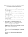
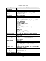
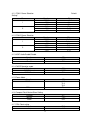
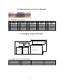
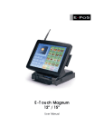
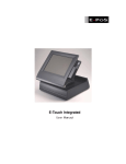
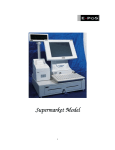
E-Pos 1000 (P4)
U s er Man u al
1
Company P r of ile
E-PoS is a pioneer in the field of Retail T echnology Products operating in Middle East & South East Asian
markets. T he success story of E-PoS started five years ago when the core focus was to meet burgeoning
market share of the mid level segment. Since then E-PoS has built a substantial market share in Retail
T echnology Products with an average growth of 10-15% per year.
E-PoS not only offers total hardware solution for the Retail business but also for Banks, Government
Organizations, Filling Stations, Hospitality I ndustry, Recreation, Hospitals etc
E-PoS has a long list of satisfied customers over the Middle East, Africa & I ndian Subcontinent. A dedicated
channel of Resellers, Dealers and System I ntegrators back up the efficient & timely distribution and After
sales service
Object ive
T he objective is to create reliable, viable & affordable retail hardware solution provider and to have
maximum satisfied customer base in the Middle East and there onwards to neighboring countries like I ndia,
Africa & Russia.
Dist r ibut ion R ight s
E-PoS represents some of the leading brands as their authorized distributor for Middle East & South East
Asia viz.:
Point of S ale
Star Micronics. U.K – for their range of Retail Technology products.
Metrologic. Germany- for Barcode scanners & Data collectors.
Godex, Taiwan – for Barcode Printers.
Cash bases U.K – for Cash Drawers.
Denso, Germany – For Auto I D Solutions
Ring, Japan – For I ndustrial Barcode Printers
2
B anking & S ecur it y
Evolis, France – For I D Card Printing solutions
Magtek, USA – For Banking products
&
A huge range of E-PoS OEM products for POS, Banking & Security Products
Pr oduct R ange
Point of S ale Pr oduct s
•
Point of Sale PCs & Web terminals
•
Touch Screen Systems
•
Printers-Line, Dot matrix, Label, Card and Point of Sale
•
Displays-Customer, CRT, Flat Panels, Touch Screen
•
Bar Code Scanners
•
Bar Code Printers
•
Cash drawers
•
Magnetic and Bar Code Swipe Readers
•
Programmable and Miniature Keyboards
•
Kiosk Terminals
•
Portable Data Terminals
•
Radio Frequency terminals
B anking and S ecur it y Pr oduct s
•
Visual Card Systems
•
I D Card printing solutions
•
MI CR Check Readers & Encoders
•
Check book, Passbook & Passport Printers
•
Counterfeit detection units
•
Note bundling and binding machines
•
Cheque printers
•
Magnetic and Bar Code Swipe Readers
•
Smart Card Readers
3
T ar get Mar ket
•
Hospitality I ndustry
•
Banks
•
Government Organizations
•
Shopping Malls
•
Filling Stations
•
Retail Business
T ar get Cust omer s
•
Dealers
•
Resellers
•
Corporate Customers
•
Overseas/Export Customers
•
System I ntegrators
•
Value Added Resellers
Cust omer Net wor k & Mar ket ing
E-PoS has existing network of dealers in the Middle East, East Africa and I ndia. T he Y2003-04 Expansion
plans include Africa and Russian continent being the emerging markets for Retail T echnology Products.
Being the only dedicated Regional distribution company for Retail technology Products, E-PoS have always
been very aggressive in terms of marketing and promotions.
Advertisements are inserted in the local press, trade journals every month. Product brochures, leaflets &
promotion schemes are distributed through mail, Fax & Electronic mail thus offering continuous updation
about EPoS product range to its business partners. E-PoS participation in I nternational trade exhibitions &
Promotions offers more insight to the dealers and corporate end users about Retail technology
4
TABLE OF CONTENTS
Introduction
-
2
Table of Contents
-
3
Location
-
4
Do’s & Don’ts
-
5
Accessories
-
6
Input /Output Function
-
7
Specifications
-
8
Jumper Settings
-
9
5
LOCATIONS
Corporate Head Quarters
Middle East
E-PoS International LLC
P.O.Box 12608
Dubai, UAE
Tel: +9714-3523288 / 3512861
Fax: +9714-3513396
Email: [email protected]
South East Asia Head Quarters
South
Asia
East E-PoS International
Nasik-Pune Road
Ayodhya Nagri
Nasik, Maharasthra
India
Tel: +91-253-2411806
Fax: +91-252-2415295
Email: [email protected]
6
DO’S & DON’TS
(Integrated circuits on All E-PoS System boards are sensitive to static electricity. To avoid
damaging any Components on the computer board, before getting started, read these following
precautions and other instructions and save them for later reference).
i.
ii.
iii.
iv.
v.
vi.
vii.
viii.
ix.
x.
xi.
xii.
xiii.
Do not remove the computer from the anti-static Packaging until you are ready for
installation.
Make sure the voltage of the power source is correct before connecting the computer to the
power outlet, (110~220 volts).
Connect Rubber Legs provided to avoid damaging Cabinet Cover and Door, (where
provided).
Do not change any Hardware Devices online when System or the device is on and running,
because the sudden surge of power may ruin any sensitive components. Also make sure the
computer is properly grounded.
Turn off the computer before cleaning. Always clean with a damp or dry cloth only. Do
not spray any liquid cleaner on screen directly.
The power outlet socket used to plug in the computer power cord must be located near the
system and easily accessible. Do not use outlets on the same circuit of the system that
regularly switch on and off.
If the computer is sharing an extension cord with other devices, make sure the total ampere
rating of the devices plugged into the extension cord does not exceed the cord’s ampere
rating.
Do not expose the power cord, extension cord and power outlet to moisture.
The openings on the computer enclosure are for the cabin ventilation to prevent the
computer from overheating. DO NOT COVER THE OPENINGS.
Do not connect any devices to Powered COM Ports (5V/12V), other then the devices that
take power from Powered COM Ports to avoid damaging the Device.
Any Hardware upgrades or changes to be made are to be informed, and do not tamper with
Serial Nos. and Warranty Seals, to avoid Warranty Void.
If the computer is not equipped with an operating system. An operating system must be
loaded first before installing any software into the computer.
If the computer is equipped with a touch panel, avoid using sharp objects to operate the
touch panel. Scratches on the touch panel may cause mal-calibration or non-function to the
panel.
xiv.
The LCD panel display is not subject to shock or vibration. When assembling the computer,
make sure it is securely installed.
xv.
Choose an Ideal dust free location and reliable surface for the System with proper
ventilations.
7
ACCESSORIES
___________________________________________________________________
1. Warranty Card.
2. Power Cable.
3. Driver Bank CD.
4. Keys.
5. CD-ROM
The following drivers in the folders of Driver Bank are necessary for driver installation.
Folder
Driver
Function
Acrobat
Acrobat Reader Installation
BIOS Tool
BIOS Update Tool
CDROMDrv
CDROM driver installation (for DOS)
Common
Elo_Touch
Touch screen driver Installation
LAN_drive
LAN driver installation
•Netmos
Enable COM5/COM6
Smart Card
Smart Card driver installation
AC97_codec_ADI
Audio driver installation
Intel845G/GL_Chipset
Chipset
initial installation
B74
Intel845G/GL-VGA
VGA driver installation
USB20
USB driver installation
Card Reader
Card Reader Test Program
Test Utility
Cash Drawer
Cash Drawer Test Program
VFD
Customer Display Test Program
8
INPUT / OUTPUT FUNCTIONS
________________________________________________________
2.1 Front View
2
3
4
1
5
2.2. Rear View
20
6
19
18
7
8
9
10
12
11
13
14
15
16
17
#
Function
#
Function
#
Function
1
2
3
4
5
6
7
Power/HDD Indicator
CD-ROM Drive
Floppy Disc Drive
Power Button
USB3/USB4(POS)
Compact Flash(POS)
USB1/USB2
8
9
10
11
12
13
14
Audio( In/Out/MIC)
PS/2 Keyboard
PS/2 Mouse
VGA
LPT
24V(POS)
COM2
15
16
17
18
19
20
Cash Drawer(POS)
COM2
LAN
COM3(POS)
2nd LPT(Optional)
COM4(POS)
* Before plugging in the Power cord, please make sure that your regional power 110V or
220V is set on the right Voltage, set up dipswitch accordingly.
9
S P E CI F I CAT I ON S
____________________________________________________________________________
Item
Motherboard
Core Logic
CPU Processor
Memory
BIOS
VGA Display
VGA memory
I/O Controller
I/O Port
Ethernet Controller
Slot on board
Audio Controller
Expansion Slot
Storage Device
Wake on
I/O Board (POS)
2nd Parallel Port
Bracket
Power Supply
Operation Temperature
EMI/EMS
Dimension
Function
B74
845GL supports 400MHz FSB
Intel P4 processor mP478-Pin
2 x DIMM DDR 200/266 Socket up to 2GB
AWARD PnP 2Mbit
Built-in Core Logic
Share Memory
W83627HF x 1, W83697 x1
Rear
2x Serial (COM1/COM2 pin1/pin9 supports 5V/
12V) Selectable
1x Parallel(DB25)
2x USB support USB 2.0
1x PS2 Keyboard
1x PS2 Mouse
1x Audio(MIC, Line-in, Line-out )
1x LAN
Front (POS)
2x USB support USB 2.0
1x Compact Flash socket
RTL 8100B 10/100Mb Fast Ethernet controller
1x 120pin PCI slot support three PCI signal for
2xPCI / LAN
Built-in Core Logic, supports AC97 2.1 w/CODEC
2x PCI option 1xPCI, 1xPCI/ISA Riser card
w/DOC socket
1x3.5” FDD
Option 1x3.5” HDD
Option 1x 5.25” Slim CD-ROM,CD-RW, DVD ROM
Support WOL(Wake on LAN) & WOR(Wake on
Ring)
COM3/COM4 pin1/9 support +5V/+12V selectable,
Cash Drawer, 24V DC
Optional
FT-8016B 160W ATX
5°– 40°C
FCC/CE Class A
300(W) x 320(D) x 90(H) mm
10
JU MP E R S E T T I N GS
4.1 Location of Main Board
11
4.1.1 COM 1 Power Selection
Default
Setting:*
Pin
Function
DCDA#
VCC
+12V
RIA#
VCC
+12V
1
9
4.1.2 COM 2 Power Selection
Pin
1
9
JP1
*1-2
3-4
5-6
*7-8
9-10
11-12
Function
DCDB#
VCC
+12V
RIB#
VCC
+12V
JP2
*1-2
3-4
5-6
*7-8
9-10
11-12
4.1.3 AC97 Audio Enable/Disable
Function
Enable
Disable
JP3
*OFF
ON
4.1.4 CMOS Operation mode
Function
CMOS Normal
CMOS Reset
JP4
*OFF
ON
4.1.5 Power Mode
Function
ATX Power
JP5
*1-2
*3-4
*5-6
7-8
AT Power
4.1.6 Compact Flash Master/Slave Setting
Function
Master
Slave
JP7
*OFF
ON
4.1.7 CPU Clock setting
Function
Auto
JP10
*1-2
12
100MHZ
2-3
4.2 Location of I/O Board
COM3
COM4
24V
Cash
Drawer
JP3
JP2
JP1
PWR1
CN1
4.2.1 COM3 Power Selection
Pin
1
9
4.2.2 COM4 Power Selection
Pin
1
9
Function
DCDC#
VCC
+12V
RIC#
VCC
+12V
JP1
*1-2
3-4
5-6
*7-8
9-10
11-12
Function
DCDD#
VCC
+12V
RID#
VCC
+12V
JP2
*1-2
3-4
5-6
*7-8
9-10
11-12
4.2.3 Cash Drawer
Function
12V
24V
JP3
*1-2
2-3
4.2.4 Cash Drawer Port Pin Assignment
Pin
Signal
1
GND
2
200H-Bit0
3
201H-Bit0
Data out address(200h)
Pin
4
5
6
13
Signal
12V/24V
200H-Bit1
GND
Data in address(201h)
4 .3 Opt i on al 2 nd P r i n t er P or t ( B r acket )
4.3.1 Printer Port Pin Assignment
#
Signal
#
Signal
1
STROBE- 6 DATA BIT4
2 DATA BIT0 7 DATA BIT5
3 DATA BIT1 8 DATA BIT6
4 DATA BIT2 9 DATA BIT7
5 DATA BIT3 10
ACK-
#
Signal
11
BUSY
12 PAPER EMP
13
SLCT
14 AUTO FEED15
ERROR-
#
16
17
18
19
20
Signal
INITSLCT INGND
GND
GND
4 .4 D augh t er B oar d( P OS 1 0 0 0 )
J8
J6
JP1
J5
J4
USB3
USB4
J1
Compact Flash
4.4.1 Compact Flash Master/Slave Setting
Function
Master
Slave
JP1
OFF
On
14
#
21
22
23
24
25
Signal
GND
GND
GND
GND
GND
______________________________________________________________________________________
E-Pos InternationalL.L.C,P.O .Box N o.12608,D ubai,U .A .E,
Tel.N o.(+9714) 3523288,Fax.N o.(+9714) 3513396,
E-M ail:eposintl@ em irates.net.ae
15