1
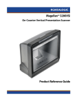
Magellan® 9500/9500Ω
9504/9504Ω
with SmartSentry®
Product Reference Guide
Datalogic Scanning, Inc.
959 Terry Street
Eugene, Oregon 97402
Telephone: (541) 683-5700
Fax: (541) 345-7140
An Unpublished Work - All rights reserved. No part of the contents of this documentation or the procedures
described therein may be reproduced or transmitted in any form or by any means without prior written permission of
Datalogic Scanning, Inc. or its subsidiaries or affiliates ("Datalogic" or “Datalogic Scanning”). Owners of Datalogic
products are hereby granted a non-exclusive, revocable license to reproduce and transmit this documentation for
the purchaser's own internal business purposes. Purchaser shall not remove or alter any proprietary notices,
including copyright notices, contained in this documentation and shall ensure that all notices appear on any reproductions of the documentation.
Should future revisions of this manual be published, you can acquire printed versions by contacting your Datalogic
representative. Electronic versions may either be downloadable from the Datalogic website (www.scanning.datalogic.com) or provided on appropriate media. If you visit our website and would like to make comments or suggestions about this or other Datalogic publications, please let us know via the "Contact Datalogic" page.
Disclaimer
Datalogic has taken reasonable measures to provide information in this manual that is complete and accurate,
however, Datalogic reserves the right to change any specification at any time without prior notice.
Datalogic is a registered trademark of Datalogic S.p.A. in many countries and the Datalogic logo is a trademark of
Datalogic S.p.A. All other brand and product names referred to herein may be trademarks of their respective owners.
This product may be covered by one or more of the following patents: 4603262 • 4639606 • 4652750 • 4672215 • 4699447 • 4709369 • 4749879
• 4786798 • 4792666 • 4794240 • 4798943 • 4799164 • 4820911 • 4845349 • 4861972 • 4861973 • 4866257 • 4868836 • 4879456 • 4939355 •
4939356 • 4943127 • 4963719 • 4971176 • 4971177 • 4991692 • 5001406 • 5015831 • 5019697 • 5019698 • 5086879 • 5115120 • 5144118 •
5146463 • 5179270 • 5198649 • 5200597 • 5202784 • 5208449 • 5210397 • 5212371 • 5212372 • 5214270 • 5229590 • 5231293 • 5232185 •
5233169 • 5235168 • 5237161 • 5237162 • 5239165 • 5247161 • 5256864 • 5258604 • 5258699 • 5260554 • 5274219 • 5296689 • 5298728 •
5311000 • 5327451 • 5329103 • 5330370 • 5347113 • 5347121 • 5371361 • 5382783 • 5386105 • 5389917 • 5410108 • 5420410 • 5422472 •
5426507 • 5438187 • 5440110 • 5440111 • 5446271 • 5446749 • 5448050 • 5463211 • 5475206 • 5475207 • 5479011 • 5481098 • 5491328 •
5493108 • 5504350 • 5508505 • 5512740 • 5541397 • 5552593 • 5557095 • 5563402 • 5565668 • 5576531 • 5581707 • 5594231 • 5594441 •
5598070 • 5602376 • 5608201 • 5608399 • 5612529 • 5629510 • 5635699 • 5641958 • 5646391 • 5661435 • 5664231 • 5666045 • 5671374 •
5675138 • 5682028 • 5686716 • 5696370 • 5703347 • 5705802 • 5714750 • 5717194 • 5723852 • 5750976 • 5767502 • 5770847 • 5786581 •
5786585 • 5787103 • 5789732 • 5796222 • 5804809 • 5814803 • 5814804 • 5821721 • 5822343 • 5825009 • 5834708 • 5834750 • 5837983 •
5837988 • 5852286 • 5864129 • 5869827 • 5874722 • 5883370 • 5905249 • 5907147 • 5923023 • 5925868 • 5929421 • 5945670 • 5959284 •
5962838 • 5979769 • 6000619 • 6006991 • 6012639 • 6016135 • 6024284 • 6041374 • 6042012 • 6045044 • 6047889 • 6047894 • 6056198 •
6065676 • 6069696 • 6073849 • 6073851 • 6094288 • 6112993 • 6129279 • 6129282 • 6134039 • 6142376 • 6152368 • 6152372 • 6155488 •
6166375 • 6169614 • 6173894 • 6176429 • 6188500 • 6189784 • 6213397 • 6223986 • 6230975 • 6230976 • 6244510 • 6259545 • 6260763 •
6266175 • 6273336 • 6276605 • 6279829 • 6290134 • 6290135 • 6293467 • 6303927 • 6311895 • 6318634 • 6328216 • 6332576 • 6332577 •
6343741 • 6454168 • 6478224 • 6568598 • 6578765 • 6705527 • 6974084 • 6991169 • 7051940 • 7170414 • 7172123 • 7201322 • 7204422 •
7215493 • 7224540 • 7234641 • 7243850• 601 26 118.6 • AU703547 • D312631 • D313590 • D320011 • D320012 • D323492 • D330707 •
D330708 • D349109 • D350127 • D350735 • D351149 • D351150 • D352936 • D352937 • D352938 • D352939 • D358588 • D361565 • D372234
• D374630 • D374869 • D375493 • D376357 • D377345 • D377346 • D377347 • D377348 • D388075 • D446524 • EP0256296 • EP0260155 •
EP0260156 • EP0295936 • EP0325469 • EP0349770 • EP0368254 • EP0442215 • EP0498366 • EP0531645 • EP0663643 • EP0698251 •
EP01330772 • GB2252333 • GB2284086 • GB2301691 • GB2304954 • GB2307093 • GB2308267 • GB2308678 • GB2319103 • GB2333163 •
GB2343079 • GB2344486 • GB2345568 • GB2354340 • ISR107546 • ISR118507 • ISR118508 • JP1962823 • JP1971216 • JP2513442 •
JP2732459 • JP2829331 • JP2953593 • JP2964278 • MEX185552 • MEX187245 • RE37166 • RE40.071 • Other Patents Pending
Table of Contents
Chapter 1. Introduction .................................................................................... 1-1
Manual Overview ........................................................................................................1-1
How to Use This Manual .........................................................................................1-2
Scanner and Scanner/Scale Nomenclature ......................................................................1-4
Connectors ..........................................................................................................1-5
Physical Parameters ....................................................................................................1-6
Scanning .............................................................................................................1-6
Deactivating EAS Tags ...........................................................................................1-6
Weighing .............................................................................................................1-7
Warm-Up Time .....................................................................................................1-8
Electrical Specifications .............................................................................................. 1-10
Power Supply ..................................................................................................... 1-10
Laser and Product Safety ........................................................................................... 1-11
Labeling ................................................................................................................... 1-13
Agency Compliances .................................................................................................. 1-14
Bar Codes Supported ................................................................................................. 1-15
Chapter 2. Site Preparation and Installation..................................................... 2-1
Pre-Installation Considerations ......................................................................................2-2
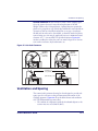
Checkstand Design ......................................................................................................2-3
Scanner Installation ....................................................................................................2-4
Scanner Maintenance ..................................................................................................2-4
References .................................................................................................................2-4
Scanner Usage ...........................................................................................................2-4
Site Preparation Overview ............................................................................................2-5
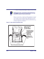
Ventilation and Spacing ...............................................................................................2-7
Service Access ............................................................................................................2-9
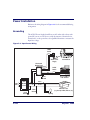
Power Installation ..................................................................................................... 2-10
Grounding .......................................................................................................... 2-10
Checkstand Preparation ............................................................................................. 2-11
Liquid Spills and Moisture ..................................................................................... 2-12
Counter Cutout ......................................................................................................... 2-12
Checkstand Mounting .......................................................................................... 2-18
Checkstand Vibration ........................................................................................... 2-18
Installation Overview ................................................................................................. 2-18
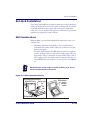
Unpacking .......................................................................................................... 2-19
Operational Verification ........................................................................................ 2-20
Diagnostic Modes ................................................................................................ 2-24
Cables & Connections .......................................................................................... 2-25
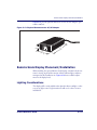
Remote Scale Display Placement/Installation ................................................................ 2-27
Lighting Considerations ........................................................................................ 2-27
Product Reference Guide
1
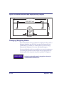
Viewing Angle ..................................................................................................... 2-28
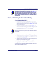
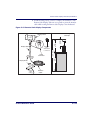
Placing and Installing the Remote Scale Display ...................................................... 2-29
Changing Weighing Modes .................................................................................... 2-32
Set-Up & Installation ................................................................................................. 2-33
EAS Considerations ............................................................................................. 2-33
Set-up ............................................................................................................... 2-36
Installation ......................................................................................................... 2-38
System Power-Up Recap ............................................................................................ 2-41
Chapter 3. Operation and Maintenance ............................................................ 3-1
Scanning Items ....................................................................................................3-1
Deactivating Security Labels ...................................................................................3-3
Proper Weighing Technique ....................................................................................3-5
Operational Controls ....................................................................................................3-6
Operational Modes ......................................................................................................3-6
Power-Up/Selftest & Pre-Operation ..........................................................................3-6
Operating Mode ....................................................................................................3-8
Additional Functions ....................................................................................................3-9
Programming .......................................................................................................3-9
Diagnostic Mode ...................................................................................................3-9
Scanner and Scale Reset ........................................................................................3-9
Scale Adjustments .............................................................................................. 3-10
Operational Maintenance ............................................................................................ 3-12
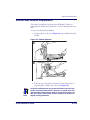
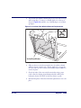
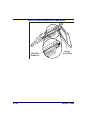
Vertical Scan Window Replacement ....................................................................... 3-13
Horizontal Scan Window Replacement (WRG) .......................................................... 3-15
Chapter 4. Problem Isolation ........................................................................... 4-1
Diagnostic Procedures ..................................................................................................4-2
Error Codes ................................................................................................................4-3
Scale Error Reporting ...................................................................................................4-5
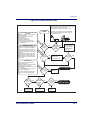
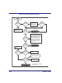
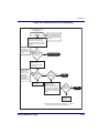
Flowcharts .................................................................................................................4-6
Chapter 5. Calibration ...................................................................................... 5-1
Description of Calibration Sequence ...............................................................................5-2
Motion Test ................................................................................................................5-3
Automatic Zero Setting Test .........................................................................................5-3
Preparing the Scanner/Scale for Calibration ....................................................................5-4
Calibrating the Scale (Pounds & Kilograms) ....................................................................5-4
Calibration Verification (U.S. Pounds) .............................................................................5-7
Increasing-Load Test (Phase 1) ...............................................................................5-7
Shift Test .............................................................................................................5-8
Increasing- Load Test (Phase 2) ..............................................................................5-9
Blanking Test .......................................................................................................5-9
Decreasing-Load Test .......................................................................................... 5-10
Return to Zero Test ............................................................................................. 5-10
Calibration Verification (Kilograms) .............................................................................. 5-11
Increasing-Load Test (Phase 1) ............................................................................. 5-11
2
Magellan® 9500
Shift Test (Metric) ............................................................................................... 5-12
Increasing- Load Test (Phase 2) ............................................................................ 5-13
Blanking Test ..................................................................................................... 5-14
Decreasing-Load Test .......................................................................................... 5-15
Return to Zero Test ............................................................................................. 5-15
Chapter 6. Programming................................................................................... 6-1
Introduction to Label Programming ................................................................................6-1
Understanding the Basics .............................................................................................6-1
Integrating the Scanner With Your Host System ..............................................................6-2
Customizing Your Scanner’s Operation .....................................................................6-2
Programming Overview ................................................................................................6-4
Programming via Handheld Device ..........................................................................6-4
What Is Programming Mode? ..................................................................................6-5
Entering and Exiting Programming Mode. .................................................................6-5
Programming Session ............................................................................................6-6
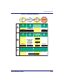
LED and Beeper Indicators ......................................................................................... 6-10
If You Make a Mistake... ............................................................................................. 6-10
Return to Factory Settings .................................................................................... 6-10
Test Mode .......................................................................................................... 6-11
General Scanner and Scale Features ............................................................................ 6-12
Double Read Timeout .......................................................................................... 6-12
Laser Timeout .................................................................................................... 6-14
Motor Timeout .................................................................................................... 6-16
Green LED Idle State ........................................................................................... 6-19
Scanner Button Options ....................................................................................... 6-20
Power-up Beep Control ........................................................................................ 6-22
Good Read Beep Control ...................................................................................... 6-24
Good Read Beep Frequency .................................................................................. 6-25
Good Read Beep Length ....................................................................................... 6-27
Good Read Beep Volume ...................................................................................... 6-28
Good Read When to Indicate ................................................................................ 6-31
Scale Enable ...................................................................................................... 6-33
Scale Country Mode ............................................................................................ 6-34
Scale Enforced Zero Return .................................................................................. 6-36
Scale Interface Type ............................................................................................ 6-38
Scale Motion Level Filter ...................................................................................... 6-40
Scale LED Enable ................................................................................................ 6-42
Remote Display — Enable/Disable ......................................................................... 6-43
Aux Port Mode .................................................................................................... 6-44
Laser Failure Mode .............................................................................................. 6-46
Productivity Index Reporting (PIR)/Cashier Training (CT) ......................................... 6-47
EAS Features ............................................................................................................ 6-48
EAS Mode .......................................................................................................... 6-48
EAS Beep Duration .............................................................................................. 6-51
EAS Retry Count ................................................................................................. 6-52
Manual EAS Deactivation Push Button .................................................................... 6-53
EAS Deactivation Duration — Coupled .................................................................... 6-56
Product Reference Guide
3
EAS Deactivation Duration — Retry ....................................................................... 6-57
EAS Deactivation Duration — Manual ..................................................................... 6-58
Interface Related Features ......................................................................................... 6-59
Interface Type .................................................................................................... 6-59
Maximum Host-Transmitted Message Length .......................................................... 6-66
Number of Host Transmission Buffers .................................................................... 6-67
Global Prefix ....................................................................................................... 6-68
Global Suffix ....................................................................................................... 6-70
IBM Features ............................................................................................................ 6-72
IBM Interface Options .......................................................................................... 6-72
IBM Scale Address .............................................................................................. 6-73
IBM Transmit Labels in Code 39 Format ................................................................. 6-75
IBM USB Interface Options ................................................................................... 6-76
IBM USB Scanner Device Type .............................................................................. 6-78
RS-232 Features ....................................................................................................... 6-79
RS-232 Baud Rate ............................................................................................... 6-79
RS-232 Number of Data Bits ................................................................................. 6-83
RS-232 Number of Stop Bits ................................................................................. 6-84
RS-232 Parity ..................................................................................................... 6-85
RS-232 Hardware Control ..................................................................................... 6-87
RS-232 Intercharacter Delay ................................................................................ 6-89
RS-232 Software Flow Control .............................................................................. 6-90
RS-232 Host Echo ............................................................................................... 6-91
RS-232 Host Echo Quiet Interval ........................................................................... 6-92
RS-232 Ignore Host Commands ............................................................................ 6-93
RS-232 TTL ........................................................................................................ 6-94
RS-232 TTL Invert ............................................................................................... 6-95
RS-232 Beep on ASCII BEL ................................................................................... 6-96
RS-232 Beep After Weigh ..................................................................................... 6-97
RS-232 Beep on Not on File .................................................................................. 6-98
RS-232 ACK NAK Enable ...................................................................................... 6-99
RS-232 ACK Character ....................................................................................... 6-101
RS-232 NAK Character ....................................................................................... 6-102
RS-232 Retry on ACK NAK Timeout ..................................................................... 6-103
RS-232 ACK NAK Timeout Value ......................................................................... 6-104
RS-232 ACK NAK Retry Count ............................................................................. 6-105
RS-232 ACK NAK Error Handling ......................................................................... 6-106
RS-232 Label ID Control .................................................................................... 6-108
Single Cable RS-232 Options .................................................................................... 6-110
Single Cable RS-232 Scanner Only Protocol .......................................................... 6-111
Single Cable RS-232 RTS CTS Selection ............................................................... 6-112
Single Cable RS-232 Use BCC ............................................................................. 6-115
Single Cable RS-232 Use ACK/NAK ...................................................................... 6-116
Single Cable RS-232 Use STX ............................................................................. 6-117
Set Single Cable RS-232 STX Character ............................................................... 6-118
Single Cable RS-232 Use ETX ............................................................................. 6-119
Set Single Cable RS-232 ETX Character ............................................................... 6-120
Symbology Programming ......................................................................................... 6-121
4
Magellan® 9500
UPC-A Enable ......................................................................................................... 6-121
UPC-A Number System Character Transmission .................................................... 6-122
UPC-A Check Character Transmission .................................................................. 6-123
Expand UPC-A to EAN-13 ................................................................................... 6-124
UPC/EAN AIM ID ............................................................................................... 6-125
UPC-A Label ID ................................................................................................. 6-126
UPC-A 2-Digit Supplemental Label ID .................................................................. 6-127
UPC-A 5-Digit Supplemental Label ID .................................................................. 6-128
UPC-A 128 Supplemental Label ID ....................................................................... 6-129
UPC-E Enable ......................................................................................................... 6-130
UPC-E Number System Character Transmission ..................................................... 6-131
UPC-E Check Character Transmission ................................................................... 6-132
Expand UPC-E to UPC-A ..................................................................................... 6-133
Expand UPC-E to EAN-13 ................................................................................... 6-134
UPC-E Label ID ................................................................................................. 6-135
UPC-E 2-Digit Supplemental Label ID ................................................................... 6-136
UPC-E 5-Digit Supplemental Label ID ................................................................... 6-137
UPC-E 128 Supplemental Label ID ....................................................................... 6-138
EAN-13 Enable ....................................................................................................... 6-139
EAN-13 First Character Transmission ................................................................... 6-140
EAN-13 Check Character Transmission ................................................................. 6-141
EAN-13 ISBN Conversion Enable ......................................................................... 6-142
EAN 13 Label ID ............................................................................................... 6-143
EAN-13 2-Digit Supplemental Label ID ................................................................. 6-144
EAN-13 5-Digit Supplemental Label ID ................................................................. 6-145
EAN-13 128 Supplemental Label ID ..................................................................... 6-146
Bookland AIM ID ............................................................................................... 6-147
Bookland Label ID ............................................................................................. 6-148
EAN-8 Enable ......................................................................................................... 6-149
EAN-8 Check Character Transmission .................................................................. 6-150
Expand EAN-8 to EAN-13 ................................................................................... 6-151
EAN 8 Label ID ................................................................................................. 6-152
EAN-8 2-Digit Supplemental Label ID .................................................................. 6-153
EAN-8 5-Digit Supplemental Label ID .................................................................. 6-154
EAN-8 128 Supplemental Label ID ....................................................................... 6-155
EAN-8 Decoding Levels ...................................................................................... 6-156
Other UPC/EAN Options ........................................................................................... 6-159
UPC/EAN Reconstruction .................................................................................... 6-160
Price Weight Check ........................................................................................... 6-161
Enable EAN Two Label ....................................................................................... 6-164
Addons ............................................................................................................ 6-165
UPC-A and EAN-13 Decoding Levels .................................................................... 6-167
GTIN Enable ........................................................................................................... 6-170
GTIN Label ID .................................................................................................. 6-171
GTIN 2-Digit Supplemental Label ID .................................................................... 6-172
GTIN 5-Digit Supplemental Label ID .................................................................... 6-173
GTIN Code 128 Supplemental Label ID ................................................................ 6-174
RSS-14 Enable ....................................................................................................... 6-175
Product Reference Guide
5
RSS-14 Check Character Transmission ................................................................. 6-176
RSS-14/EAN-128 Emulation ............................................................................... 6-177
RSS-14 2D Component Enable ............................................................................ 6-178
RSS-14 AIM ID ................................................................................................. 6-179
RSS-14 Label ID ............................................................................................... 6-180
RSS Expanded Enable .............................................................................................. 6-181
RSS Expanded EAN-128 Emulation ...................................................................... 6-182
RSS Expanded 2D Component Enable .................................................................. 6-183
RSS Expanded AIM ID ....................................................................................... 6-184
RSS Expanded Label ID ..................................................................................... 6-185
RSS Expanded Length Control ............................................................................. 6-186
RSS Expanded Maximum Label Length ................................................................. 6-187
RSS Expanded Minimum Label Length .................................................................. 6-188
RSS Expanded Fixed Length 1 ............................................................................. 6-189
RSS Expanded Fixed Length 2 ............................................................................. 6-190
Code 39 Enable ....................................................................................................... 6-191
Code 39 Start Stop Character Transmission .......................................................... 6-192
Code 39 Check Character Calculation ................................................................... 6-193
Code 39 Check Character Transmission ................................................................ 6-194
Code 39 Full ASCII ............................................................................................ 6-195
Code 39 AIM ID ................................................................................................ 6-196
Code 39 Label ID .............................................................................................. 6-197
Code 39 Length Control ..................................................................................... 6-198
Code 39 Maximum Label Length .......................................................................... 6-199
Code 39 Minimum Label Length .......................................................................... 6-200
Code 39 Fixed Length 1 ..................................................................................... 6-201
Code 39 Fixed Length 2 ..................................................................................... 6-202
Code 39 Stitching .............................................................................................. 6-203
Pharmacode 39 Enable ............................................................................................. 6-204
Pharmacode 39 Start Stop Character Transmission ................................................ 6-205
Pharmacode 39 Check Character Transmission ...................................................... 6-206
Pharmacode 39 Label ID .................................................................................... 6-207
Code 128 Enable ..................................................................................................... 6-208
Code 128 Transmit Function Characters ............................................................... 6-209
Convert Code 128 to Code 39 ............................................................................. 6-210
Code 128 AIM ID .............................................................................................. 6-211
Code 128 Label ID ............................................................................................ 6-212
Code 128 Length Control .................................................................................... 6-213
Code 128 Maximum Label Length ........................................................................ 6-214
Code 128 Minimum Label Length ......................................................................... 6-215
Code 128 Fixed Length 1 .................................................................................... 6-216
Code 128 Fixed Length 2 .................................................................................... 6-217
Code 128 Stitching ............................................................................................ 6-218
EAN-128 Enable ...................................................................................................... 6-219
EAN-128 AIM ID ............................................................................................... 6-220
EAN-128 Label ID ............................................................................................. 6-221
Interleaved 2 of 5 (I 2 of 5) Enable ............................................................................ 6-222
I 2 of 5 Check Character Calculation .................................................................... 6-223
6
Magellan® 9500
I 2 of 5 Check Character Transmission ................................................................. 6-224
I 2 of 5 AIM ID ................................................................................................. 6-225
I 2 of 5 Label ID ............................................................................................... 6-226
I 2 of 5 Length Control ...................................................................................... 6-227
I 2 of 5 Maximum Label Length ........................................................................... 6-228
I 2 of 5 Minimum Label Length ............................................................................ 6-229
I 2 of 5 Fixed Length 1 ...................................................................................... 6-230
I 2 of 5 Fixed Length 2 ...................................................................................... 6-231
I 2 of 5 Stitching ............................................................................................... 6-232
Codabar Enable ...................................................................................................... 6-233
Codabar Start Stop Character Transmission .......................................................... 6-234
Codabar Start Stop Character Set ....................................................................... 6-235
Codabar Start Stop Character Match .................................................................... 6-237
Codabar Check Character Calculation ................................................................... 6-238
Codabar Check Character Transmission ................................................................ 6-239
Codabar AIM ID ................................................................................................ 6-240
Codabar Label ID .............................................................................................. 6-241
Codabar Length Control ..................................................................................... 6-242
Codabar Maximum Label Length ......................................................................... 6-243
Codabar Minimum Label Length .......................................................................... 6-244
Codabar Fixed Length 1 ..................................................................................... 6-245
Codabar Fixed Length 2 ..................................................................................... 6-246
Codabar Stitching ............................................................................................. 6-247
Code 93 Enable ...................................................................................................... 6-248
Code 93 AIM ID ................................................................................................ 6-249
Code 93 Label ID .............................................................................................. 6-250
Code 93 Length Control ..................................................................................... 6-251
Code 93 Maximum Label Length .......................................................................... 6-252
Code 93 Minimum Label Length .......................................................................... 6-253
Code 93 Fixed Length 1 ..................................................................................... 6-254
Code 93 Fixed Length 2 ..................................................................................... 6-255
Code 93 Stitching ............................................................................................. 6-256
MSI/Plessey Enable ................................................................................................. 6-257
MSI/Plessey Check Character Calculation ............................................................. 6-258
MSI/Plessey Number of Check Characters ............................................................ 6-259
MSI/Plessey Check Character Transmission .......................................................... 6-260
MSI/Plessey AIM ID ........................................................................................... 6-261
MSI/Plessey Label ID ......................................................................................... 6-262
MSI/Plessey Length Control ................................................................................ 6-263
MSI/Plessey Maximum Label Length .................................................................... 6-264
MSI/Plessey Minimum Label Length ..................................................................... 6-265
MSI/Plessey Fixed Length 1 ................................................................................ 6-266
MSI/Plessey Fixed Length 2 ................................................................................ 6-267
MSI/Plessey Stitching ........................................................................................ 6-268
Standard 2 of 5 Enable ............................................................................................ 6-269
Standard 2 of 5 Check Character Calculation ........................................................ 6-270
Standard 2 of 5 Check Character Transmission ..................................................... 6-271
Standard 2 of 5 AIM ID ...................................................................................... 6-272
Product Reference Guide
7
Standard
Standard
Standard
Standard
Standard
Standard
Standard
2
2
2
2
2
2
2
of
of
of
of
of
of
of
5
5
5
5
5
5
5
Label ID .................................................................................... 6-273
Length Control ........................................................................... 6-274
Maximum Label Length ............................................................... 6-275
Minimum Label Length ................................................................ 6-276
Fixed Length 1 ........................................................................... 6-277
Fixed Length 2 ........................................................................... 6-278
Stitching ................................................................................... 6-279
Appendix A. LED/Beeper Indications & Controls ................................. A-1
Controls and Indicators ............................................................................................... A-2
LED and Beeper Indications ................................................................................... A-2
Volume/Tone Push Button ..................................................................................... A-6
Manual EAS Deactivation Push Button ..................................................................... A-8
Scale Zero Push Button ......................................................................................... A-9
Calibration Switch ...............................................................................................A-10
Appendix B. Cable Information............................................................ B-1
Introduction ..............................................................................................................
General Specifications ..........................................................................................
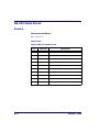
RS-232 Cable Pinout ...................................................................................................
Scanner ..............................................................................................................
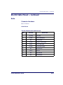
RS-232 Cable Pinout — continued ................................................................................
Scale ..................................................................................................................
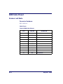
IBM Cable Pinout ........................................................................................................
Scanner and Scale ...............................................................................................
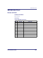
IBM USB Cable Pinout .................................................................................................
Scanner and Scale ...............................................................................................
Auxilliary Port ............................................................................................................
External Handheld Input .......................................................................................
Power Cable ..............................................................................................................
Connector Hardware .............................................................................................
Remote Display ..........................................................................................................
Connector Hardware .............................................................................................
EAS Comm Port .........................................................................................................
EAS Deactivator Control Box Connection .................................................................
B-1
B-1
B-2
B-2
B-3
B-3
B-4
B-4
B-5
B-5
B-6
B-6
B-7
B-7
B-8
B-8
B-9
B-9
Appendix C. Keypad............................................................................. C-1
Appendix D. Host Commands............................................................... D-1
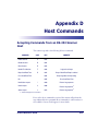
Accepting Commands from an RS-232 Scanner Host ....................................................... D-1
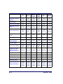
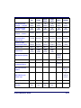
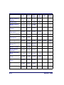
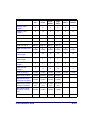
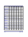
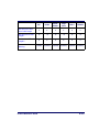
Appendix E. Factory Defaults............................................................... E-1
Appendix F. Handheld Data Format Requirements............................... F-1
Handheld Data Format Requirements General ...........................................................F-1
Datalogic Handheld Data Format Requirements .........................................................F-2
AIM Formats ...................................................................................................... F-10
8
Magellan® 9500
DATALOGIC SCANNING, INC. MAGELLAN® END USER LICENSE
AGREEMENT
Notice to End User: The Datalogic Product you have acquired contains embedded Software, which is integral to the product's operation. This
Software is being provided to you under license, subject to the terms and conditions of this Agreement. If you use the Datalogic Product, you will
be deemed to have accepted the terms and conditions of this Agreement. If you do not intend to be bound to the terms of this Agreement, Datalogic is not willing to license the Software to you, you may not use the Datalogic Product or the Software, and you must contact the party from
whom you acquired the Datalogic Product for instructions.
This End User Software License Agreement ("Agreement") is a legally binding agreement governing the licensing of the Software and Documentation by Datalogic,Scanning Holdings, Inc. and its subsidiaries and affiliates ("Datalogic") to the entity or person who has purchased or otherwise acquired a Datalogic
Product ("End User"). For purposes of this Agreement, any software that is associated with a separate end-user license agreement is licensed to you under
the terms of that license agreement. Datalogic and End User hereby agree as follows:
1. Definitions.
1.1
1.2
1.3
1.4
"Documentation" means materials such as user's guides, program reference guides, quick reference guides, manuals, or similar materials associated
with or related to the Datalogic Product, whether in printed, "online", or other form.
"Proprietary Information" means: (a) source code, object code, software, documentation, and any related internal design, system design, data base
design, algorithms, technology, technical data or information, implementation techniques, and trade secrets related to the Software, (b) any other trade
secrets marked appropriately or identified as proprietary or confidential, and (c) any information that End User, under the circumstances, should recognize as confidential. Proprietary Information does not include any information that the receiving party can establish was (1) in the public domain, (2)
already in the receiving party's possession or rightfully known prior to receipt, (3) rightfully learned from a third party not in violation of any other's proprietary rights, or (4) independently developed without access to Proprietary Information.
"Datalogic Product" means the Datalogic Magellan® 1000i series, Magellan® 1400i series, Magellan® 8100 series, Magellan® 8200 series, Magellan® 8300 series, Magellan® 8400 series, Magellan® 8500 series, Magellan® 9500 series, and/or Magellan SL® series scanner and/or scanner/scale
product, including all embedded Software in and all Documentation related to such product, which has been purchased or otherwise acquired by End
User, whether obtained directly or indirectly from Datalogic.
"Software" means any software or computer programs of Datalogic or its third party licensors in machine readable form which is embedded in the Datalogic Product, whether obtained directly or indirectly from Datalogic, including any replacement, update, upgrade, enhancement or modification.
2. Scope Of License Granted.
2.1
2.2
Datalogic grants to End User a non-exclusive, non-transferable, perpetual license to use the Software, solely on the Datalogic Product in which it is
embedded ("designated Datalogic Product"), in machine-readable form only, solely for End User's internal business purposes. This Agreement does
not convey ownership of the Software to End User. Title to the Software shall be and remain with Datalogic or the third party from whom Datalogic has
obtained a licensed right. As used in this Agreement, the term "purchase" or its equivalents when applied to the Software shall mean "acquire under
license." End User is not entitled to receipt or use of the source code to any Software.
End User shall not copy, modify, decompile, disassemble, reverse engineer, or otherwise reproduce or remanufacture the Software, whether modified
or unmodified, nor sell, assign, sublicense, distribute, lend, rent, give, or otherwise transfer the Software to any other person or organization, for purposes other than as expressly provided in this Agreement, without Datalogic's prior written consent.
3. Transfers, Support.
3.1
3.2
3.3
Any copying, installing, reproduction, remanufacture, reverse engineering, electronic transfer, or other use of the Software on other than the designated Datalogic Product will be a material breach of this Agreement. However, Datalogic may elect not to terminate this Agreement or the granted
licenses, but instead may elect to notify End User that End User is deemed to have ordered and accepted a license for each breaching use. End User
shall pay Datalogic the applicable list price for such licenses as of the date of such breach.
End User shall not sell, assign, sublicense, distribute, lend, rent, give, or otherwise transfer the Datalogic Product to any third party unless such third
party agrees with Datalogic in writing to be bound by the terms and conditions of this Agreement. Any such transfer of the Datalogic Product absent
such agreement shall be null and void.
End User may obtain support for Software from Datalogic at Datalogic's standard support fees and under Datalogic's standard support terms and conditions in effect at the time the support is requested.
4. Intellectual Property.
End User acknowledges that the Software constitutes valuable trade secrets of Datalogic or Datalogic's third party licensors and that the Software is protected by intellectual property laws and treaties. The license set forth in this Agreement does not transfer to End User any ownership of Datalogic's or its third
party licensors' copyrights, patents, trademarks, service marks, trade secrets, or other intellectual property rights and End User shall have no right to commence any legal actions to obtain such rights. End User shall not remove, modify, or take any other action that would obscure any copyright, trademark,
patent marking, or other intellectual property notices contained in or on the Datalogic Product.
5. Proprietary Information.
5.1
5.2
5.3
End User acknowledges that Proprietary Information is the confidential, proprietary, and trade secret property of Datalogic and Datalogic's third party
licensors and End User acquires no right or interest in any Proprietary Information.
End User shall not disclose, provide, or otherwise make available the Proprietary Information of Datalogic or its third party licensors to any person
other than End User's authorized employees or agents who are under confidentiality agreement, and End User shall not use the Proprietary Information other than in conjunction with use of the Datalogic Product exclusively for End User's internal business purposes. End User shall take steps to
protect the Proprietary Information no less securely than if it were End User's own intellectual property.
The provisions of this Proprietary Information Section shall survive and continue for five (5) years after the termination of this Agreement.
6. Limited Warranty.
6.1
Datalogic warrants that, under normal use and operation, the Datalogic Product will conform substantially to the applicable Documentation for the
period specified in the Documentation. During this period, for all reproducible nonconformities for which Datalogic has been given written notice, Datalogic will use commercially reasonable efforts to remedy nonconformities verified by Datalogic. End User agrees to supply Datalogic with all reasonably
requested information and assistance necessary to help Datalogic in remedying such nonconformities. For all defects reported to Datalogic within the
warranty period, Datalogic's liability is limited to providing End User with one copy of corrections or responding to End User's problem reports accord-
Product Reference Guide
9
6.2
ing to Datalogic's standard assistance practices. Datalogic does not warrant that the product will meet End User's requirements or that use of the product will be uninterrupted or error free, or that Datalogic's remedial efforts will correct any nonconformance. This limited warranty does not cover any
product that has been subjected to damage or abuse, whether intentionally, accidentally, or by neglect, or to unauthorized repair or unauthorized installation, and shall be void if End User modifies the product, uses the product in any manner other than as established in the Documentation, or if End
User breaches any of the provisions of this Agreement.
EXCEPT AS PROVIDED IN THIS AGREEMENT, THE DATALOGIC PRODUCT IS PROVIDED "AS IS" AND DATALOGIC MAKES NO WARRANTIES
OF ANY KIND, EXPRESS OR IMPLIED, WRITTEN OR ORAL, WITH RESPECT TO THE PRODUCT, AND SPECIFICALLY DISCLAIMS THE
IMPLIED WARRANTIES OF MERCHANTABILITY AND FITNESS FOR A PARTICULAR PURPOSE.
7. Infringement.
7.1
7.2
7.3
7.4
Datalogic will defend End User against any claim in a lawsuit that the Datalogic Product furnished hereunder infringe a United States patent or copyright of a third party and Datalogic will pay any damages finally awarded against End User by a court of competent jurisdiction that are attributable to
such claim or will pay End User's part of any settlement that is attributable to such claim, provided, that 1) End User notifies Datalogic promptly in writing of the claim, 2) Datalogic controls the defense or settlement of the claim, and 3) End User cooperates fully with Datalogic in such defense or settlement. All notices of a claim should be sent to Datalogic Scanning Holdings, Inc., Legal Department, 959 Terry Street, Eugene, OR 97402.
In the defense or settlement of any such claim, Datalogic may, at its option, 1) procure for End User the right to continue using the Datalogic Product,
2) modify the Datalogic Product so that it becomes non-infringing, 3) replace the Datalogic Product with an equivalent product not subject to such
claim, or 4) provide End User an opportunity to return the Datalogic Product and receive a refund of the purchase price paid, less a reasonable allowance for use.
Datalogic shall have no liability to End User for claims of infringement based upon 1) the use of any Datalogic Product in combination with any product
which Datalogic has not either furnished or authorized for use with such Datalogic Product 2) the use of any Datalogic Product designed, manufactured, or modified to the specifications of End User, or 3) End User's modification of the Datalogic Product without written authorization from Datalogic.
THE FOREGOING STATES DATALOGIC'S COMPLETE AND ENTIRE OBLIGATION CONCERNING CLAIMS OF PATENT, COPYRIGHT, OR OTHER
INTELLECTUAL PROPERTY INFRINGEMENT, CANCELS AND SUPERSEDES ANY PRIOR AGREEMENTS, WHETHER ORAL OR WRITTEN,
BETWEEN THE PARTIES CONCERNING SUCH CLAIMS, AND WILL NOT BE MODIFIED OR AMENDED BY ANY PAST, CONTEMPORANEOUS,
OR FUTURE AGREEMENTS OR DEALINGS BETWEEN THE PARTIES, WHETHER ORAL OR WRITTEN, EXCEPT AS SET FORTH IN A FUTURE
WRITING SIGNED BY BOTH PARTIES.
8. Limitation Of Liability.
EXCEPT AS PROVIDED IN SECTION 7, DATALOGIC SHALL NOT BE LIABLE FOR ANY CLAIMS AGAINST END USER BY ANY OTHER PARTY. IN NO
EVENT SHALL DATALOGIC'S LIABILITY FOR DAMAGES, IF ANY, WHETHER BASED UPON CONTRACT, TORT (INCLUDING NEGLIGENCE), PRODUCT LIABILITY, STRICT LIABILITY, WARRANTY, OR ANY OTHER BASIS, EXCEED THE PRICE OR FEE PAID BY END USER FOR THE DATALOGIC
PRODUCT. UNDER NO CIRCUMSTANCES SHALL DATALOGIC BE LIABLE TO END USER OR ANY THIRD PARTY FOR LOST PROFITS, LOST DATA,
INTERRUPTION OF BUSINESS OR SERVICE, OR FOR ANY OTHER SPECIAL, CONSEQUENTIAL, CONTINGENT, INDIRECT, INCIDENTAL, PUNITIVE,
EXEMPLARY, OR OTHER SIMILAR DAMAGES, EVEN IF DATALOGIC HAS BEEN ADVISED OF THE POSSIBILITY OF SUCH DAMAGES.
9. Government Restricted Rights; International Use.
9.1
9.2
Use, duplication, or disclosure of the Software by the U.S. Government is subject to the restrictions for computer software developed at private
expense as set forth in the U.S. Federal Acquisition Regulations at FAR 52.227-14(g), or 52.227-19 or in the Rights in Technical Data and Computer
Software clause at DFARS 252.227-7013(c)(1)(ii), whichever is applicable.
If End User is using the Datalogic Product outside of the United States, End User must comply with the applicable local laws of the country in which the
Datalogic Product is used, with U.S. export control laws, and with the English language version of this Agreement. The provisions of the "United
Nations Convention on International Sale of Goods" shall not apply to this Agreement.
10. Termination.
10.1
10.2
Either party may terminate this Agreement or any license granted under this Agreement at any time upon written notice if the other party breaches any
provision of this Agreement.
Upon termination of this Agreement, End User immediately shall cease using any non-embedded software and shall return to Datalogic or destroy all
non-embedded software covered by this Agreement, and shall furnish Datalogic with a certificate of compliance with this provision signed by an officer
or authorized representative of End User. For embedded software, End User agrees to sign a waiver prepared by Datalogic concerning further use of
the embedded Software. End User's resumed or continued use of the embedded Software after termination shall constitute End User's agreement to
be bound by the terms and conditions of this Agreement for such use.
11. General Provisions.
11.1
11.2
11.3
11.4
11.5
Entire Agreement; Amendment. This document contains the entire agreement between the parties relating to the licensing of the Software and supersedes all prior or contemporaneous agreements, written or oral, between the parties concerning the licensing of the Software. This Agreement may not
be changed, amended, or modified except by written document signed by Datalogic.
Notice. All notices required or authorized under this Agreement shall be given in writing, and shall be effective when received, with evidence of receipt.
Notices to Datalogic shall be sent to the attention of Contract Administration, Datalogic Scanning Holdings, Inc., 959 Terry Street, Eugene, OR 97402,
or such other address as may be specified by Datalogic in writing.
Waiver. A party's failure to enforce any of the terms and conditions of this Agreement shall not prevent the party's later enforcement of such terms and
conditions.
Governing Law; Venue: This Agreement and the rights of the parties hereunder shall be governed by and construed in accordance with the laws of the
State of Oregon U.S.A, without regard to the rules governing conflicts of law. The state or federal courts of the State of Oregon located in either Multnomah or Lane counties shall have exclusive jurisdiction over all matters regarding this Agreement, except that Datalogic shall have the right, at its
absolute discretion, to initiate proceedings in the courts of any other state, country, or territory in which End User resides, or in which any of End User's
assets are located.
Attorneys’ Fees. In the event an action is brought to enforce the terms and conditions of this Agreement, the prevailing party shall be entitled to reasonable attorneys' fees, both at trial and on appeal.
- END -
10
Magellan® 9500
Chapter 1
Introduction
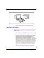
This Product Reference Guide contains comprehensive instructions on
how to install the scanner or scanner/scale (either model may be termed
“scanner” for the purpose of simplicity in this manual), how to program it
using special programming feature bar code labels, and advanced user
information as described in the following overview.
Manual Overview
Chapter 1, Introduction, presents the manual’s contents, describes features
and specifications, provides regulatory and safety information, and lists
the bar code symbologies the scanner will read.
Chapter 2, Site Preparation and Installation, supplies physical dimensions
for the scanner or scanner/scale and its most common accessories, and
details counter preparation and installation. Cable routing, connection
and testing are also explained in this chapter.
Chapter 3, Operation and Maintenance, describes use and maintenance;
providing details about operator controls, programming and diagnostic
modes, scale “zeroing” and calibration. Scanner and scale routine maintenance are outlined in this chapter as well.
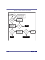
Chapter 4, Problem Isolation, provides an outline of three scanner/scale
test modes: Selftest, Operational Tests and Diagnostic Tests. Descriptions
of the error indications if the scanner detects a system problem and troubleshooting flowcharts to aid in problem resolution are also presented.
Chapter 5, Calibration, explains scale calibration and verification proce-
dures, including procedures for calibrating the scale in pounds as well as
kilograms.
Product Reference Guide
1-1
Chapter 6, Programming, details procedures and provides custom bar-
codes for setting programmable scanner and scanner/scale features. This
chapter is organized by the categories: General Features, Interface Related
Features and Symbology Related Features.
Appendix A, LED/Beeper Indications & Controls, lists the various functions
and indications of the scanner/scale control panel features.
Appendix B, Cable Information, outlines wire requirements, connector
specifications and pinout details for associated product cabling.
Appendix C, Keypad, furnishes bar codes representing the digits and characters required to enter extended programming data needed during certain
programming sessions.
Appendix D, Host Commands, contains a partial listing of available host
commands that can be used with a compatible host interface.
Appendix E, Factory Defaults, is a table providing factory default pro-
grammable settings for common interfaces.
Appendix F, Handheld Data Format Requirements, provides application
notes describing the general format of data accepted by the scanner
through the auxilliary port as transmitted from a handheld scanner.
How to Use This Manual
You’ll find it helpful to familiarize yourself with the first chapter of this
manual, since it provides both a general description of the product’s features and an overview of the manual’s contents and organization. Reference the other chapters as required for information about scanner or
scanner/scale installation, operation, maintenance, calibration and bar
code programming.
1-2
Magellan® 9500
Manual Overview
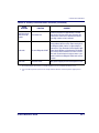
Manual Conventions
‘NOTE’ blocks contain information that is helpful and recommended. They provide information that is critical to
operations and/or procedures described in this manual.
LEGAL NOTE
‘LEGAL NOTE’ blocks indicate procedures or activities
which may be regulated under law by governmental
agencies. It is your responsibility to ensure compliance
with the regulations that govern installation of weighing
devices.
‘CAUTION’ blocks inform you that proper handling
(adherence to the procedures described) is required to
avoid damage to equipment and/or property.
‘WARNING’ blocks alert you to potential physical harm or
injury. These statements do not include potentially fatal
hazards, which would be designated as ‘DANGER’
blocks. Use of this product does not warrant the need for
a DANGER block.
Product Reference Guide
1-3
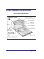
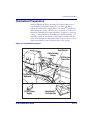
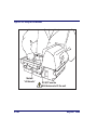
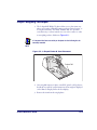
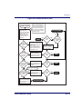
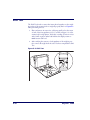
Scanner and Scanner/Scale Nomenclature
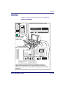
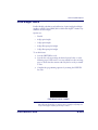
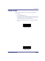
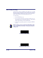
Controls, indicators and other nomenclature are shown in Figure 1-1.
Figure 1-1. Scanner/Scale Nomenclature
Volume/Tone Push Button
Scanner LED (Green)
Weighing Surface — Lean
Oversize Produce Here
Scale LED (Yellow)
EAS LED
(Tri-Color)
Bonnet
Scale Zero
Push Button
Manual EAS
Deactivation Push
Button
Vertical Window
Horizontal Window
Produce Rail
All Weighs™ Platter
1-4
Magellan® 9500
Scanner and Scanner/Scale Nomenclature
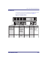
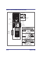
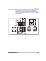
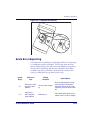
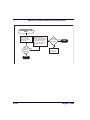
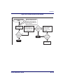
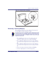
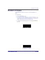
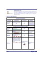
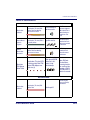
Connectors
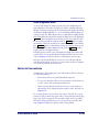
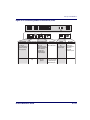
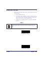
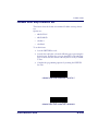
The appearance of the connector panel will vary depending upon the factory options purchased with your model. Reference Figure 1-2.
Figure 1-2. Connector Panel
0.00
POS Terminal
POS TERMINAL
Remote Display
Aux. Port
Scale Host
REMOTE DISPLAY AUXILLIARY PORT
· Label Data
Drives Remote Display
· Scale Data (for
single cable interfaces)
· Application Download
(where appropriate)
Models with scale
only
Product Reference Guide
SCALE HOST
· Test Port
Scale Data (dual
· On Screen
cable scanner/scale)
Programming (OSP)
· Application Download
· RS-232 Handheld
Scanner Input
· Auxilliary RS-232
Label Data Output
Connection to
this port is
Optional
Power
POWER
AC Brick Input
OR
Power off Terminal
(POT) Brick Input
EAS Port
EAS PORT
Connection to
external Sensormatic® ScanMax ProTM
controller box.
Controls EAS
deactivation system.
Dual cable units only.
(Scale connection may
be handled through
POS Terminal port)
1-5
Physical Parameters
This chapter provides specifications for performance, environmental and
electrical parameters. Reference the second chapter of this manual, Site
Preparation and Installation, for physical measurements of all models and
some accessories.
Scanning
The scanner has a scan zone between the two windows where the scanner
projects laser light in order to scan items. Two separate projections, one
from the horizontal window and one from the vertical window, combine
to form a zone where bar code labels are read. Refer to Chapter 3, "Scanning Items" for more information.
Deactivating EAS Tags
Deactivation of Sensormatic® ScanMax ProTM EAS (Electronic Article
Surveillance) anti-theft labels is an additional function that can be performed by the scanner. More information about this feature can be referenced under the following topics:
1-6
•
Chapter 2, "EAS Considerations"
•
Chapter 3, "Deactivating Security Labels"
•
Chapter 6, "EAS Features"
Magellan® 9500
Physical Parameters
Weighing
Specifications for scale capacity, settling time, minimum and maximum
static weight, zeroing, and warm-up time are given below. For more information regarding the topic: Proper Weighing Technique, refer to the Operation and Maintenance chapter of this manual.
Rated Weight Capacity
The scale’s operational weight capacity is:
•
30.00 pounds, displayed in 0.01 increments
OR
•
15.000 kilograms1, displayed in 0.005 increments.
Minimum Increment
The minimum weight that can be accurately measured by the scale is 0.02
lb. (0.005 kg).
Maximum Static Weight (Overload)
A maximum static weight of 150 pounds (68 kg) can be sustained by the
scale without incurring damage or degrading performance.
Automatic Zero Maintenance
The scale’s software constantly monitors and adjusts the Zero point as
long as the deviation is within acceptable limits2, while compensating for
any debris accumulation or removal. During power-up, the scale automatically re-zeros after verifying that all subsystems are functional. Additionally, the scale may be manually “zeroed” by pushing the Scale Zero Push
Button located on the top of the vertical enclosure.
1. The scale can also be set for 9.99 kg max.
2. Acceptable limitis of deviation are set at -0.2 to +0.6 pounds (-0.078kg to 0.23kg), which is -0.67 to
+2.0% of total capacity.
Product Reference Guide
1-7
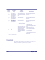
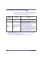
Warm-Up Time
There are two pertinent warm-up times that apply to the scanner or scanner/scale:
The two warm-up periods can be performed concurrently, thereby reducing
the total required warm-up time to 60 minutes.
NOTE
Thermal Equilibrium
When the unit is moved from a cooler temperature (such as a storage area)
to a warmer environment (such as a checkstand location), 60 minutes
must be allowed to acclimate the unit to ambient conditions prior to calibration or operation.
Power-up
Once installed and powered up, a warm-up time of 15 minutes must be
allowed before calibrating or performing weighing operations.
User Configurable Warm-up
The user may configure the unit for a pre-programmed warm-up time
that is activated every time the scanner is powered up. During this time,
the scale is viewed by the POS terminal as off-line.
Contact technical support to learn more about this advanced programmable feature.
NOTE
1-8
Magellan® 9500
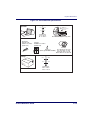
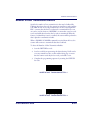
Physical Parameters
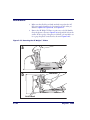
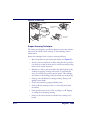
Figure 1-3. Environmental Specifications
Operation
+40 C
10 C
+104 F
50 F
Temperature
10 to +40 C
50 to +104 F
Illumination
Artificial Light:
0-450 Foot-candles
(4,842 LUX)
Dust Resistant Optics Cavity, IP5X
Sunlight:
0-8,000 Foot-candles
(86,080 LUX)
Spill Proof
(Datalogic MS-0006-13-0004)
Humidity
Hot / Wet 40°C / 95% RH
Hot / Dry 40°C / 5% RH
Cold / Dry 10°C / 5% RH
Warm / Wet 25%C / 50% RH
Storage
+70 C
-40 C
POS
+158 F
-40 F
Scan
ner
Temperature
-40 to +70 C
-40 to +158 F
Product Reference Guide
1-9
Electrical Specifications
Before installation, always verify that the site’s electrical service meets the
scanner/scale’s requirements. The scanner has been engineered for compatibility with most international electrical systems operating in ranges
from 100 to 240VAC at 50-60 Hz. Verify that the power source will supply “clean” electrical power to the equipment; that is, it must be free of
excess electrical noise.
Check the IEC power cord shipped with the scanner/scale. If the cord will
not plug into your AC power receptacle, the power cord shipped is not
compatible with your electrical system. Please contact your distributor
immediately to receive the necessary information and components to
ensure electrical compatibility.
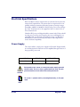
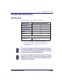
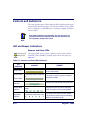
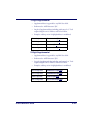
Power Supply
The scanner utilizes a single power supply for all models. Unique installation and international connections are accomplished through selection of
the proper IEC power cord
VOLTAGE
FREQUENCY
PART NUMBER
100-240VAC ±10%
50-60 Hz
8-0582
Safe operation of your scanner or scanner/scale requires properly grounded
electrical outlets. Be sure to have a qualified electrician certify the earthground connection on circuits which will be used to power the unit.
CAUTION
The scanner is powered on/off by connecting/disconnecting its AC power
supply.
NOTE
1-10
Magellan® 9500
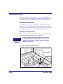
Laser and Product Safety
Laser and Product Safety
Laser safety requirements are based on IEC Standard Publication 60825-1
(2001) and CDRH 21CFR, Chapter 1, Subchapter J and (CDRH) Laser
Product Performance Standard, User information [1040.10(h)1]:
•
User Maintenance. No user maintenance of the system other than
cleaning of the scan windows is required.
•
Radiant Energy. The scanner is an IEC Class 1 and CDRH IIa laser
product. The system uses two embedded Class 3B Visible Laser
Diodes (VLDs). No attempt should be made by the user to remove
the protective housing of the scanner/scale.
•
Laser Light Viewing. The horizontal and vertical scan windows are
the only apertures through which laser light may be observed in this
product.
Exposure to the light emitted from the scan windows has been shown not
to be harmful. The safety record of bar code scanning is perfect after millions of hours of use worldwide. This safe and efficient use of laser technology has gained wide acceptance in industries throughout the world.
Operators and installers of the unit should observe the following cautions
and warnings:
Use of controls, adjustments or performance of procedures other than those
specified herein may result in hazardous laser light exposure.
CAUTION
The use of optical instruments with the scanner will increase eye hazard.
(Optical instruments include binoculars, microscopes, telescopes and magnifying glasses. This does not include eyeglasses worn by the user).
To prevent exposure to laser light, do not remove the protective housing of
the scanner. There are no user-serviceable parts inside your scanner or
scanner/scale.
Product Reference Guide
1-11
Safety precautions to be taken:
No adjustments or alteration of the scanner or scanner/scale housing are to
be attempted by the user.
CAUTION
WARNING
The failure of the facet wheel motor while the unit is continuing to emit a
laser beam causes the emission levels to exceed those for inherently safe
operation. The unit has safeguards to prevent this occurrence. If, however, a
stationary laser beam is ever emitted, the failing unit should be disconnected
from its power supply until repaired by a qualified technician.
This equipment has been tested and found to comply with the limits for a
Class A digital device, pursuant to part 15 of the FCC Rules. These limits are
designed to provide reasonable protection against harmful interference
when the equipment is operated in a commercial environment. This equipment generates, uses, and can radiate radio frequency energy and, if not
installed and used in accordance with the instruction manual, may cause
harmful interference to radio communications. Operation of this equipment
in a residential area is likely to cause harmful interference in which case the
user will be required to correct the interference at his or her own expense.
This Class A digital apparatus meets all requirements of the Canadian
Interference-Causing Equipment Regulations.
Cet appareil numerique de la classe A respecte toute les exigences du
Reglement sur le material broilleur du Canada.
1-12
Magellan® 9500
Labeling
Labeling
Regulatory, reference and safety labeling is shown in Figure 1-4.
Figure 1-4. Labeling
III
N max = 3000
Max 15 kg
Min 0.1 kg
e = 0.005 kg
Max 30 lbs
Min 0.2 lb
e = 0.01 lb
Or...
Located on EAS Single-Antenna models
n max= 3000
III
emin= .01 lb
NTEP: 02 - 043
AM - 5454
IEC CLASS 1 LASER PRODUCT
CAPACITE
15.000 x .005 kg
CAPACITY
30.00 x .01 lb
+10°c to +40°c
6-0928
Class IIa Laser Product. Avoid long term viewing of direct laser light.
Appareil à laser de classe IIa. Éviter toute exposition prolongée de la vue à lumière laser directe.
Producto Laser Clase lla. Evite mirar, de manera continua, directamente a la luz del laser.
U.S., CANADA, MEXICO AND JAPAN
+10°C/+40°C
90/384/EEC
Located inside Optics Chassis
M
Located on Spider
Assembly (Scale
Models ONLY)
Two labels located on
EAS Dual-Antenna models
• CAUTION - CLASS 3R LASER RADIATION WHEN OPEN. AVOID DIRECT EYE EXPOSURE.
• ATTENTION - RAYONNEMENT LASER DE CLASSE 3R CARTER OUVERT. EVITEZ L'EXPOSITION
DIRECTE DE L'OEIL.
• ACHTUNG - NACH ÖFFNUNG LASERSTRAHLUNG NACH KLASSE 3R AUGENKONTAKT MIT
LASERSTRAHL VERMEIDEN.
• PRECAUCIÓN - CUANDO ABIERTO, EMITE RAYO LASER DE LA CLASE 3R.
• ADVERTÊNCIA - QUANDO ABERTO, EMITE RAIO DE LASER DA CLASSE 3R.
• ATTENZIONE - RADIAZIONI LASER CLASSE 3R SE APERTO. EVITARE L'ESPOSIZIONE DIRETTA
AGLI OCCHI.
• VARNING - KLASS 3R LASERSTRÅLNING UTAN FÖRSLUTNING. UNDVIK DIREKT ÖGONKONTAKT.
Sa
tes fet
ted
n
ctio
du red
Pro nito
mo
y
This device complies with Part 15 of the FCC Rules.
Operation is subject to the following two conditions:
(1) this device may not cause harmful interference, and
(2) this device must accept any interference received,
including interference that may cause undesired operation.
•
•
•
Product of USA
PRODUCT SERVICE
N263
NRTL
CLASS 1 LASER PRODUCT
LASER KLASSE 1
CATAGORIA 1 PRODUCTO LASER
APPAREIL Á LASER DE CLASSE 1
based on 10 sec; IEC 60825-1:2001
U
S
THIS LASER PRODUCT COMPLIES WITH 21CFR 1040
AS APPLICABLE AS A CLASS IIA PRODUCT
This Class A digital apparatus complies with Canadian ECES-003.
Cet appareil numérique de la Classe A est confirme à la norme NMB-003 du Canada.
Input: 50 - 60 Hz (0.5 - 0.25A)
90 - 265VAC (P/N 8-0559)
COVERED BY ONE OR MORE OF THE FOLLOWING U.S. PATENTS: 4,709,195 4,709,369 4,712,853 4,749,879 4,786,798 4,792,666 4,798,943 4,799,164
4,816,660 4,861,972 4,861,973 4,866,257 4,868,836 4,879,456 4,963,719 4,991,692 5,144,118 5,179,270 5,198,649 5,247,162 5,229,588 5,410,108
5,459,308 5,440,110 5,475,207 5,493,108 5,705,802 5,723,852 5,834,708 5,929,421 6,059,189 6,237,852 RE37,166 OTHER PATENTS PENDING
Power: 18 Watts (max)
Output:
+5V at 2.0A
+12V at 0.7A
0.00
POS Terminal
Remote Display
Aux. Port
Scale Host
Power
EAS Port
MAGELLAN 9500
This illustration shows general label placement ONLY. Actual label
appearance and location may vary. View the labels on the product, or
contact your nearest sales or service office for regulatory, patent and other
information.
Product Reference Guide
1-13
Agency Compliances
The scanner and scanner/scale meets or exceeds the requirements for its
device type as set forth by the following agencies and regulations:
COUNTRY
COMPLIANCE
COMMENTS
Electrical
United States
UL 60950
TÜV NRTL/UL
Canada
CAN/CSA C22.2 No. 60950
TÜV NRTL/UL
World
IEC60950 / IEC 825-1:2001
TÜV CB
Emmisions
United States
47CFR Part 15J
FCC
Canada
ICES-0003
Class B
Europe
EN 55022
Class B
Safety & Emissions
EMC Directive 89/336/EEC
CE Mark
LV Directive 73/23/EEC
CE Mark
Laser Safety
United States
CDRH, 21CFR Part 1040
CDRH Class IIa laser device
Canada
same as CDRH
SGM-1 specification
Weights & Measures
United States
NIST Handbook 44 (Dept. of Commerce)
Canada
Measures Canada
New York
New York Certificate
EU
90/384/EEC Directive
NWML
OImL
R76-1 and R76-2
NSC
Contact Datalogic® Product Marketing at (541) 683-5700, or your Datalogic representative for a complete listing
of approvals for other countries.
1-14
Magellan® 9500
Bar Codes Supported
Bar Codes Supported
The scanner can read/decode the following bar code types (symbologies):
•
UPC Versions A & E
•
UPC Supplementals and Add-ons (2 & 5 digit supplimentals, Coupon code and Code 128)
•
Plural Stage Dual UPC Bar Codes for Japan ( 2 label read)
•
Reduced Space Symbology (RSS) RSS-14, RSS expanded, RSS
Stacked
•
EAN-8 & 13
•
JAN-8 & 13
•
UCC/EAN-128
•
Code 39
•
Code 39 full ASCII
•
Code 128 (including conversion to Code 39)
•
Code 93
•
Interleaved 2 of 5 (I 2 of 5)
•
Italian Pharmacode (Code 39)
•
Codabar
•
MSI/Plessey
Product Reference Guide
1-15
NOTES
1-16
Magellan® 9500
Chapter 2
Site Preparation and
Installation
This chapter provides a reference for preparing most checkstands to
receive the scanner or scanner/scale. Included are physical parameters and
instructions for checkstand preparation, power and ventilation considerations, cable routing information and unit installation.
Site Preparation lists all procedures necessary to prepare the checkstand.
The instructions that follow, titled Checkstand Preparation, detail steps for
the three models that are available (shown in Figure 2-1 below) to facilitate easy installation into almost any checkstand application around the
world:
Model 9501 — Scanner only
Model 9502 — Scanner/Scale
Some models are designed to fit with little or no modification into openings cut for previously installed scanners such as Magellan® scanners, or
NCR® scanner models 7820/24 and 7870. Other models are designed for
applications with smaller footprint requirements.
Once the procedures in this chapter are complete, the scanner is ready for
scanning operation1; with the exception that if a scanner/scale was
installed, calibration will be required before placing the unit into operation. You must consult the local weights and measures authority to ensure
that all legal requirements are met concerning calibration and certification. Chapter 5, Calibration, contains detailed procedures for calibrating
the scale in either pounds or kilograms.
1. Electronic Article Surveillance (EAS) operation requires the installation of the Sensormatic® ScanMax ProTM antenna and controller.
Product Reference Guide
2-1
Figure 2-1. 9500 Models
Model 9501
Model 9502
Pre-Installation Considerations
It should be noted that the scope of this manual does not encompass all
factors related to worker safety and checkstand design. It does, however,
offer a list of considerations that may be helpful in ensuring greater safety
and productivity. Careful planning using these general guidelines should
result in a more efficient, comfortable work environment.
The U.S. Bureau of Labor Statistics reports that the incidence of repetitive
motion injuries has increased dramatically in recent years. Checkstand
design and scanner installation and operation procedures can reduce the
risk of repetitive motion injuries, but not eliminate it.
Although there are currently no formal guidelines for checkstand ergonomics, the Food Marketing Institute (FMI) and the National Institute of
Occupational Safety (NIOSH) of the Department of Health and Human
Services have released the reports listed at the end of these recommendations. These reports contain useful suggestions for ergonomic improvement of checkstand designs and scanner installation, maintenance and
usage. Portions of the reports are summarized below. For copies of the
complete reports, or to inquire about any modifications to the recommendations, contact FMI and NIOSH at the addresses listed at the end of
these recommendations.
2-2
Magellan® 9500
Checkstand Design
Checkstand Design
1. Select a design which allows load-sharing by several muscle groups
(for example designs which allow the cashier to use both hands for
scanning and bagging).
2. Select checkstands which deliver products to the cashier on an input
belt and do not require the unloading of items from a cart. These
designs put less stress on the cashiers’ shoulders and back.
3. Minimize the distance between the input and take-away conveyors
(i.e., the distance the cashier has to reach to move the products).
4. Minimize the width of the input conveyor to reduce the cashier’s
reach to items on the far side of the belt; use a diverter to direct
products closer to the cashier.
5. Select a design which encourages the cashier to slide products across
the scanner rather than gripping and lifting. Make sure the horizontal surface of the scanner is flush with all surrounding surfaces.
6. Choose a design which integrates the scanner and scale to eliminate
extended reaches and lifts during weighing tasks.
7. Provide an easily accessible bag stand at a height 13 - 17 inches (33 43.2 cm) lower than the top surface of the checkstand to reduce
stresses to the shoulders, elbows, and risks associated with lifting
products into bags.
8. Do not position the bag stand between the cashier and the scanner,
due to the increased reach involved.
9. Position the scanner’s horizontal scanning surface 34 - 36 inches
(86.4 - 91.4 cm) above the floor. Maintain a minimum of five
inches (12.7 cm) clearance between elbows and work surfaces.
10. Provide adjustable keyboard mounting (height, tilt, and horizontal
reach).
11. Position the printer, cash drawer, and other checkstand devices the
cashier uses within easy reach (less than 18 inches/45.7 cm).
12. Provide adequate toe space, foot rests or rails, antifatigue mats, and
where feasible, an adjustable seat or stand against which the cashiers
can lean.
Product Reference Guide
2-3
Scanner Installation
1. Mount the horizontal surface of the scanner flush with the countertop to encourage slide scanning rather than lifting.
2. Position the centerline of the scanner read area 8 - 10 inches (20.3 25.4 cm) from the edge of the checkstand (cashier side).
Scanner Maintenance
1. Keep scanner windows clean. This will improve productivity and
reduce rescans.
2. Replace scanner glass when excessive scratches are evident.
References
Anonymous, 1992, “Ergonomic Improvement of Scanning Checkstand
Designs”,
Food Marketing Institute
800 Connecticut Ave. N.W.
Washington, D.C. 20006
Grant, Katharyn A. et al., 1992, “Ergonomic Evaluation of Checkstand
Designs in the Retail Food Industry”,
National Institute of Occupational Safety and Health
4676 Columbia Parkway
Cincinnati, Ohio 45226
Scanner Usage
1. Minimize handling of heavy/bulky products. Leave these items in
the cart and use an alternative entry method such as key entry of
short PLUs, or handheld scanning.
2. Regularly train cashiers in proper scanning methods and ergonomics
principles, such as:
2-4
Magellan® 9500
Site Preparation Overview
Develop a smooth fluid motion during scanning, sharing
work equally between hands.
Use the entire hand for grasping and lifting items.
Since the scanner reads labels on all four sides plus the top
and bottom, there is no need to turn a bar code toward either
of the scanner windows.
Develop efficient scanning motions, not necessarily faster
hand movements. Simply slide the item across the scanner’s
horizontal window with as little orientation motion as necessary.
Leave items in an upright position; do not lift and tilt.
Learn how the scanner functions and where the scanning area
is located.
Do not favor either the vertical or horizontal window; slide
items across the scanner in their natural orientations on the
checkstand as much as possible.
Site Preparation Overview
Consider the following factors before installing the scanner or scanner/
scale and its optional Remote Scale Display.
Ventilation Requirements: The scanner operates without the use of a
ventilation fan. As long as there is adequate convective air flow and no
major heat producing equipment in close proximity, the unit’s housing
provides adequate heat dissipation. The air temperature in the checkstand
around the scanner must not exceed 104°F (40°C).
Service Access Requirements: Routine operations such as ‘zeroing’
and calibration do not require removal of the scanner from the checkstand
or disassembly of the product. The installer should plan service access for
the AC/DC Power Supply and cables.
Product Reference Guide
2-5
Recommended Power Installation: Since the typical grocery envi-
ronment includes conveyor belts and electric motors, care should be taken
to ensure that the scanner has a supply of “clean” power (power without
excessive electrical noise). A wiring diagram shows the recommended wiring that will provide the scanner with a “clean” source of power. Refer to
Figure 2-4.
Counter Preparation: Since the majority of grocery checkout lanes are
designed as “left-hand take away,” the counter drawings in this chapter
focus on this counter design. Simply reverse the layout for a “right-hand
take away” requirement. The unit scans equally well in either of these two
configurations.
Liquid Drainage: Should a liquid spill occur, ensure that moisture can
flow through the checkstand without pooling.
Leveling: Plan ahead and provide screws/bolts in the checkstand mounts
and a leveling guide (board) to allow leveling of the scanner or scanner/
scale within the counter. Use a 0.375” thick board to replicate the mounting flange on the long scanner or scanner/scale, and adjust screws or bolts
until the board is flush within the counter. Use a 4.0” wide board stood on
its end to adjust leveling screws/bolts in rail support applications.
Cable Routing: Placement of the scanner/scale should be planned to
allow easy access to other components as well as optimize communication
between the scanner, the POS terminal, the optional Remote Scale Display and the Sensormatic® ScanMax ProTM controller. Note that cables
may drop straight down from the scanner’s connector panel, or may be
conveniently routed along the unit’s side using the hardware provided. Do
not route interface cables near any electrical motors or other sources of
electromagnetic interference.
Remote Scale Display Placement: The customer, and checker in
some instances, must be able to easily view and read the Remote Scale Display. Ambient light and mounting height considerations are discussed
later in this chapter.
2-6
Magellan® 9500
Ventilation and Spacing
Vertical Clearance: Provision must be made to allow adequate space
above the scanner bonnet for removal and replacement of the All
Weighs™ Platter (the L-shaped platter). Optimal clearance permits the
platter to be grasped at its top vertical edge and lifted for removal without
obstruction (such as a fixed keyboard mount or any type of enclosure).
Should such an enclosure be unavoidable, an alternate method of platter
removal using two coins may be employed, however a minimum vertical
clearance of 1.5” (3.8 cm) MUST be provided (reference Figure 2-2).
Another consideration is that the scan zone must be kept free of obstructions such as enclosures, keyboard mounts, etc.
Figure 2-2. Vertical Clearance
DO NOT
Obstruct
L-Platter
Removal
(Keyboard Mount)
DO NOT
Obstruct
Scan Zone
Allow a minimum
clearance of
1.5" (3.8cm)
(Enclosure)
Ventilation and Spacing
The scanner/scale’s perimeter housing has been designed to provide adequate space for convective cooling and unrestricted movement of the
weighing apparatus. Figure 2-3 shows the debris chutes and ventilation
slots. The checkstand design must allow:
•
Product Reference Guide
The ambient air temperature inside the checkstand adjacent to the
scanner must not exceed 104°F (40°C).
2-7
•
A source of air that provides adequate cooling by convective air flow.
DO NOT place the scanner in a close-fitting, fully enclosed checkstand. Provide a MINIMUM of 16 square inches (103.2 square centimeters) of air intake
from below the installation for sufficient convective cooling.
NOTE
If motors, conveyor belts, or other heat producing equipment are located
near the scanner, forced air ventilation may be required. In most installations, a 30 cfm (.84 cmm) axial fan should provide sufficient air movement. If a ventilation fan is installed, one with a removable filter that may
be washed or replaced is recommended.
Figure 2-3. Debris Chutes & Ventilation Slots
Spider Assembly
(Present only
in scale models)
Illustration shows
a Single-Antenna
EAS model installed in a
right-to-left
position. Your
installation may
vary.
Debris Chutes/Ventilation Slots
2-8
Magellan® 9500
Service Access
Service Access
The scanner and scanner/scale have been engineered to allow performance
of all routine service and maintenance (such as “zeroing” and calibration)
without removing the scanner from the checkstand. Additionally all cable
connections made at the scanner can be connected and removed while the
unit is sitting on the countertop. The installer should provide service
access to all remaining cable connectors as well as the AC/DC Power Supply (if installed).
Product Reference Guide
2-9
Power Installation
Reference the wiring diagram in Figure 2-4 for the recommended fusing
arrangement.
Grounding
The AC/DC Power Supply should have an AC outlet with a clean earth
ground. If you are not sure how to verify the amount of electrical noise
(interference) on the power line, ask a qualified electrician to measure the
input line voltage.
Figure 2-4. Input Power Wiring
On/Off
Switch
AC/DC Power
Supply
Scanner or
Scanner/Scale
Checkstand
Breaker Panel
Neutral
Line
Ground
On/Off
Switch
Neutral
Line
Ground
Panel
Ground
Power
Mains
2-10
Neutral
Main
Breaker
Panel
Panel
Ground
POS Terminal
Line
Ground
Inductive Loads
(e.g. Conveyor Belts, Motors, etc)
Earth
Ground
Lighting
Magellan® 9500
Checkstand Preparation
Checkstand Preparation
Reference Figure 2-5. When performing a first time installation into a
new checkstand, verify before cutting that room will be allowed for
cabling, the AC/DC Power Supply, and the Sensormatic® Controller Box.
When making the opening, take extra care to accurately cut to the correct
dimensions. Mounting may require installation of support(s), countertop
routing, or other such devices. Depending upon checkstand design, you
may wish to install an item diverter to direct items toward the scan window. See the instructions in this manual titled “Counter Cutout” for more
details concerning the location and preparation of the opening.
Figure 2-5. Installation Overview
Item Diverter
Cable Routing
Groove
EAS Service
Connection
POS
Term
inal
Remo
te Displa
y
0.00
Aux.
Port
Scale
Host
Powe
r
EAS
Port
Connector
Bulkhead
AC/DC Power
Supply
Product Reference Guide
Sensormatic®
Controller Box
2-11
Liquid Spills and Moisture
Select a checkstand design which allows fluids to flow through, and directs
liquids away from any electronic equipment or storage areas.
Counter Cutout
The most important consideration when planning the counter opening
for the scanner is the operator’s comfortable reaching distance. The ideal,
ergonomically sound installation allows items to be directed within easy
reach, and a scanning area requiring no lifting or special orientation of
items. If you haven’t already read the information at the beginning of this
chapter titled, Pre-Installation Considerations, please do so before continuing these instructions.
The symmetrical design of the scanner permits the operator to easily pass
items from one hand to the other while scanning (either from right-to-left
or left-to-right). With the unique 360- scan zone, scanning is accomplished in one fluid motion. The operator simply slides the item from the
conveyor belt or diverter area through the scanning area and passes the
item to the other hand, which in turn bags it or places it on a take-away
conveyor belt. Movement should flow naturally over the surface of the
scanner.
Note that the following guidelines for preparing an existing checkstand to
accept a scanner, or incorporating the unit into a new checkstand design
will not be accurate for all installations. Although these guidelines will suffice for most standard installations, the installer may need to make adjustments for varying counter heights and thicknesses, support design, or
other checkstand limitations.
Figure 2-6 shows a typical “left-hand-take-away” checkstand design.
Follow these basic steps to install the unit:
1. Select a position for the scanner that offers a smooth product flow
which best accommodates the reaching distance of the average operator.
2. Cut the opening in the countertop. Reference Figure 2-7 for cutout dimensions.
2-12
Magellan® 9500
Counter Cutout
3. Install the AC/DC Power Supply, the Remote Scale Display cable
and the interface cable(s) observing the following:
Interface cables (and display cable, if applicable) should be
routed away from all highly inductive electrical devices, like
motors and conveyor belts, and even away from the unit’s
power cable if possible.
Cables should be easy to remove in the event that replacement is required. A little planning now will save a lot of frustration later.
4. Connect and verify all system operations.
The scanner should be installed so that leading and trailing edges of the
All Weighs™ Platter are flush with the countertop to enhance smooth,
slide-through scanning (reference the insert in Figure 2-6). Keep in mind
that the debris chutes on both sides of the platter provide the necessary
clearance for proper scale operation if you are installing a scanner/scale
(you won’t need to provide an additional gap for that).
Product Reference Guide
2-13
Figure 2-6. Typical Checkstand Design & Cutout Location
Remote Display
Conveyor
POS Terminal
& Printer
Optional
Item Diverter
Deadplate
6.3"
(16.0cm)
Scanner
Keyboard
Cash Drawer
(Below Scanner)
Scan & Bag
Well
(Optional)
Check
Writing
Stand
(Optional)
Flush — Correct
Take-Away
Belt
Bagging
Area
Above Flush — Incorrect
Below Flush — Incorrect
2-14
Magellan® 9500
Counter Cutout
Refer to Figure 2-7 for dimensional information. Figure 2-8 and
Figure 2-9 provide counter cutout details for model 850x/950x interchangeability and minimum required counter cutout (for new 950x installations) respectively.
Figure 2-7. Dimensions
Window
7.0" (17.78cm)
8.0"
(20.32cm)
8.6"
(21.84cm)
13.5"
(34.29cm)
6.5" (16.51cm)
17.76"
(45.11cm)
11.5"
(29.21cm)
SCANNER
11.1"
(28.19cm)
PLATTER
11.9"
(30.23cm)
28.9 lb.
(13.1kg)
22.2 lb.
(10.1kg)
Scanner/Scale
Weight
Scanner
Weight (w/o scale)
20.0"
(50.8cm)
Product Reference Guide
2-15
Figure 2-8. Cutout Dimensions: Recommended for 8500/9500 Interchangeability
20.125"
(51.12cm)
18.625"
(47.30cm)
Max. Radius = 0.25"
(0.64cm) 4x
Rail
0.75"
(1.9cm)
11.625"
(29.53cm)
3.0" ± .03"
(7.62 ± .76mm)
(Center Line)
Rail
0.75"
(1.9cm)
If leveling feet are needed,
use the placement shown here,
represented with plus signs (+).
3.0" ± .03"
(7.62 ± .76mm)
0.37" ± .030"
(0.94 ± 0.07 cm)
0.37" ± .03"
(0.94 ± 0.07 cm)
20.125" ±0.06"
(51.2 ±0.15 cm)
0.375" ± 0.03"
(.95 ±.08 cm)
0.75"
(1.9 cm)
1.5"
(3.8 cm)
0.75"± .060"
(1.9 ±0.15 cm)
4.0"
(10.2 cm)
2-16
0.75"± .060"
(1.9 ±0.15 cm)
Liquid
Drainage
18.625" ± .060"
(47.3 ±0.15 cm)
Liquid
Drainage
Magellan® 9500
Counter Cutout
Figure 2-9. Cutout Dimensions: Minimum Required Counter Cutout
20.09 ± 0.06"
(51.03 ± 0.15cm)
17.88 ± 0.06"
(45.26 ± 0.015cm)
Max. Radius = 0.25"
(0.64cm) 4x
Rail
1.22"
(3.1cm)
11.562"
(29.367cm)
3.0" ± .03"
(7.62 ± .76mm)
(Center Line)
Rail
1.0"
(2.54cm)
If leveling feet are needed,
use the placement shown here,
represented with plus signs (+).
3.0" ± .03"
(7.62 ± .76mm)
.50" ± .030"
(1.27 ±0.07 cm)
0.61" ± .03"
(1.55 ±0.07 cm)
20.09" ± 0.06"
(51.03 ± 0.15cm)
0.375" ± 0.03"
(.95 ±.08 cm)
0.75"
(1.9 cm)
1.5"
(3.8 cm)
1.18"± .060"
(3.00 ± 0.15 cm)
4.0"
(10.2 cm)
Product Reference Guide
1.00"± .060"
(2.54 ± 0.15 cm)
Liquid
Drainage
17.88 ± 0.06"
(45.26 ± 0.015cm)
Liquid
Drainage
2-17
Checkstand Mounting
There are a number of things to take into account when installing the unit
into a checkstand. Key factors are ergonomic/worker safety, loading capacity and stability. Consider the scanner or scanner/scale’s weight when calculating the robustness of construction needed to support it as well as
maximum capacity of weighed and scanned items.
NOTE
If you choose to rout a countertop with a thickness of 0.75” (1.9 cm) plywood,
you’ll need to add a backing strip that supports the area routed out for the
support flanges (see Figure 2-5). This support strip should minimally be
made of 0.75” (1.9 cm) thick plywood and be approximately 4.0” (10.2 cm)
wide and 14.0” (35.6 cm) long. This strip should be glued as well as screwed
to the underside of the countertop.
Checkstand Vibration
Proper function of the scanner/scale is dependent upon an installation
which minimizes excess vibration from conveyor belts, fans, and other
such equipment. See Chapter 4, Scale Error Reporting, if vibration is suspected of causing operational problems.
Installation Overview
The preceding Site Preparation Overview dealt with installed location and
counter preparations to accommodate the scanner or scanner/scale. Having completed those steps, physical installation of the scanner or scanner/
scale can begin. The following instructions apply to all models.
This chapter describes:
1. Unpacking the unit.
2. Verifying operation before connecting to a POS system.
3. Routing and connecting cables.
4. Validating that your scanner communication parameters match the
POS terminal’s system requirements.
5. Confirming connection to the EAS system.
6. Functional testing to verify operation when connected to the POS
system.
2-18
Magellan® 9500
Installation Overview
The following text describes each of these steps.
Unpacking
To unpack the unit:
•
Inspect the package for signs of damage that may have occurred during shipping. If damage is found, report it to your carrier immediately.
•
Lift out the accessory box containing the AC/DC Power Supply,
optional Remote Scale Display and cable (if present), and the Quick
Reference Guide.
•
Remove the Quick Reference Guide and familiarize yourself with
the unit’s controls and features. Leave the guide at the checkstand
when the installation is complete.
•
Remove the protective packing and carefully lift the unit from the
carton. Be sure to save the box and all packing material. In the event
of failure, the unit must be returned to the factory in its original
packaging.
•
Carefully lift off the All Weighs™ Platter as shown in Figure 2-22
and remove the protective foam pieces securing the weigh mechanism. Set the platter back in place.
For added protection during shipment, the All Weighs™ Platter is covered
with a tight-fitting layer of vinyl as shown in Figure 2-10. This vinyl layer
MUST BE REMOVED before placing the unit into service.
NOTE
Product Reference Guide
2-19
Figure 2-10. Remove Protective Vinyl
Protective vinyl
MUST be removed
from the
platter
before use.
•
Proceed to the Operational Verification instructions below.
Operational Verification
Follow these steps to ensure that your unit has arrived undamaged and is
fully functional before installing it in the counter and connecting it to
your POS system.
1. Connect the scanner and the EAS antenna to the EAS Controller
Box (see Figure 2-20 and Figure 2-21) and power-on the controller
box.
2. If the unit is a scanner/scale, connect the Remote Scale Display to
the proper connector on the unit’s connector panel (refer to
Figure 2-14). Note that if the Remote Scale Display is not connected, a scanner power-up Selftest will sound a long, low beep, and
the number “8” will appear on the 7-segment display indicating a
remote display error. Power-down, connect a known-good Remote
Display to the appropriate port, and restart to correct this problem.
Alternatively, you can disable the Remote Display using programming bar codes (see Chapter 6, Programming for more information).
3. Connect the power cable at the scanner, then at the AC outlet.
2-20
Magellan® 9500
Installation Overview
When power is applied to the unit, the normal indicator sequence is:
•
The scanner indicator (top-most, green LED) will be lit (dim)
steadily.
•
The EAS indicator (bottom-most, tri-color LED) will flash ON/
OFF during power-up. Additionally, the 7-segment display will
flash the number ‘9’. indicating the EAS system is being initialized.
•
If the Selftest detects a problem, the 7-segment display will display a
number code. Refer to Chapter 4, Problem Isolation, for a description of failure codes and problem isolation procedures.
Scale calibration may be necessary to obtain a zero reading on the display on
rare occasions.
NOTE
4. The unit should be permitted to reach thermal equilibrium before
proceeding to the next steps. (Reference the topic Warm-Up Time in
Chapter 1.) When the unit is moved from a cooler temperature
(such as a storage area) to a warmer environment (such as a checkstand location), a period of 60 minutes must be allowed to acclimate
the unit to ambient conditions. Once installed and powered up, a
“power-up” warm-up period of 15 minutes must be allowed before
calibrating or performing weighing operations. These two warmup periods may run concurrently.
5. Verify that the scanner or scanner/scale passes an operational test by
observing the following:
Product Reference Guide
2-21
Scanner: Pass UPC/EAN bar code labels in front of the scanner’s win-
dows. Since the interface cable is not yet connected to the POS terminal, the scanner may be limited to reading only one or two labels
(see the note that follows). The scanner indicates when each label
has been successfully read by flashing the green scanner light and
emitting a good read tone (beep).
NOTE
When not connected to the host, the scanner may be limited to reading only
one or two labels. (This limitation is dependent upon the interface type.) To
scan multiple labels without connecting to the host, place the unit in Scanner
Diagnostic Mode by pressing the Volume/Tone Push Button for four seconds.
EAS System: The way in which EAS tags are deactivated is dependent
upon the way the scanner is currently programmed with regard to EAS
Mode. (See “EAS Mode” on page 6-48.) To test EAS system function...
2-22
•
Coupled Mode — Pass an item containing both a bar code and an
active EAS tag over the scanner. Successful deactivation is indicated
by the bottom-most LED flashing first red, then orange, then
returning to green. The beeper will sound a good read beep.
If you have enabled the manual deactivation function available for
Coupled Mode (see “Manual EAS Deactivation Push Button” on
page 6-53), test the function by pressing the bottom push button. A
ticking sound will be heard which should cease upon deactivating an
EAS tag.
•
Decoupled Mode — In this mode, items do not require a bar code
to be scanned to arm the deactivation function. Simply pass an
active EAS tag over the scanner in the same direction you would
scan a bar code. The bottom-most LED will flash red to indicate
deactivation. No beep is sounded to indicate deactivation in this
mode.
•
Hybrid Mode — In Hybrid Mode, the scanner must be enabled,
however EAS deactivation in this mode also takes place without
needing to scan an item’s bar code. Pass an active EAS tag over the
scanner in the same direction you would scan a bar code. The bottom-most LED will flash red, then orange, then return to green.
The beeper may be configured to sound a high frequency beep to
announce successful deactivation.
Magellan® 9500
Installation Overview
Scale: If the Yellow (middle, scale) LED is not lit, press the Scale Zero
Push Button momentarily. If the scale is operating correctly, the yellow LED will illuminate and remain on steady, and the display will
show a reading of 0.00 lb (0.000 kg for metric). If the display is
blank or a
is displayed, it may be necessary to calibrate
-0the scale before continuing. Refer to Chapter 5, Calibration, for calibration procedures.
Remote Scale Display: Check to verify that 0.00 lb (0.000 kg for met-
ric) is displayed, then place an item on the weighing platter. Verify
that the display shows a weight and that the yellow LED goes out.
Remove the item and observe that Remote Scale Display shows 0.00
lb (0.000 kg for metric) and that the yellow LED is On.
6. Unplug the AC power cord from the outlet and disconnect the
power cord and Remote Scale Display cable from the scanner’s connector panel.
After you have verified that the scanner, EAS system and scale (if present)
are completely functional, continue with the following procedures to
complete the installation.
Product Reference Guide
2-23
Diagnostic Modes
Two diagnostic modes are available which allow you to initiate scanner or
scale diagnostic tests, as well as verify the scanner’s ability to read bar
codes.
Scanner Diagnostic Mode
While in Scanner Diagnostic Mode, continuous scanning of labels is
allowed, permitting the user to scan an unlimited number of bar codes
while troubleshooting problems. Under normal operation, the scanner
stores label data, awaiting the signal which transmits it to the host. When
the scanner is not connected to a host, it may read and store only up to
two labels, then quit reading until power is cycled (clearing the memory).
This mode of operation removes this limitation.
To place the scanner in Scanner Diagnostic Mode, press the Volume/Tone
Push Button for approximately four seconds. While pressing the button,
the scanner will first sound three tones, wait a few seconds, then sound six
rapid tones; after which you should immediately release the button.
While in Scanner Diagnostic Mode, identification numbers for interface1
type, firmware and configuration will scroll continually across the scanner’s 7-segment FRU (Field Replaceable Unit) display. This is useful information for field diagnostics. See Figure 4-1 for the location of the display.
For example, if the dual cable RS-232 interface (type 05) were enabled,
the firmware designation was R96-1234, and the configuration was R965593, the following would be shown (slowly, with blanking between each
of the items):
IF-05 r96-1234 r96-5593.
To exit Scanner Diagnostic Mode, cycle power to the unit or press and
hold the Volume/Tone Push Button for eight seconds to reset the scanner.
See the topic, Scanner and Scale Reset in Chapter 3 for more information
about unit resets.
1. A listing of scanner interface identification numbers is available in Chapter 6, under the topic,
Interface Type.
2-24
Magellan® 9500
Installation Overview
Scale Diagnostic Mode
To enter Scale Diagnostic Mode, press the Scale Zero Push Button for
approximately four seconds. Six rapid tones will be sounded, indicating
the unit is leaving normal operation and entering Scale Diagnostic Mode.
The Remote Display will flash a ‘1’ across the display while the dignostic
routine is being run. When diagnostics are completed successfully, the display will indicate that the unit has passed the diagnostic test by displaying
PASS
. Next, the display shows a listing of how many times the unit
has been calibrated and zeroed in the form of: c XXX where x equals
the number of times the scale has been calibrated. Next, the unit will display Zero XXXX where x is the number of times the scale has been zeroed.
Finally, all segments will be displayed in the form of: -18.8.88
c XXX to allow
visual verification of display function.
If the diagnostics routine is not completed successfully, the scanner will
sound a series of tones and the Remote Display will show an error code.
Turn to Chapter 4, Problem Isolation for a description of error codes.
Press the Scale Zero Push Button once more to reset the unit and exit
Scale Diagnostic Mode. See the topic, Scanner and Scale Reset in Chapter
3 for more information about unit resets.
Cables & Connections
Considerations when routing the power and interface cables for the scanner and scanner/scale are:
•
Ensure that cables are not pinched, kinked or pierced.
•
Do not route interface cables in close proximity to electrical motors
or other sources of electromagnetic interference.
•
Cables can drop directly from their connectors on the scanner, or,
alternatively, can be routed along the scanner’s side to the back (see
Figure 2-11).
Do not plug the AC power cord into the outlet at this time. It is a good
practice to always connect the power cable to the scanner first before plugging it into the AC receptacle. The procedures titled, Set-Up, provided
later in this chapter will instruct you to connect the power cord at that
time. Figure 2-11 illustrates the basic cable routing scheme.
Product Reference Guide
2-25
Figure 2-11. Cable Routing
Keyboard
Alternate
Cable
Routing
Remote
Display
POS Terminal, Printer &
Cash Drawer
Scanner
AC Power
Switch
(recommended)
AC/DC
Power
Supply
AC Power
Remote Scale
Display Cable Scanner
(optional
Interface
Scanner/Scale) Cable
EAS Antenna Cable
EAS Controller Box
Scale
Interface
Cable
(Scanner/Scale)
Optional
EAS Interface Cable
2-26
Magellan® 9500
Remote Scale Display Placement/Installation
Figure 2-12 provides physical dimensions for the AC/DC Adapter (part
number 8-0582).
Figure 2-12. Physical Measurements: AC/DC Adapter
2.3"
(5.8 cm)
3.1"
(7.8 cm
)
1"
5.5 )
m
c
(14
Remote Scale Display Placement/Installation
When installing the optional Remote Scale Display, consider both the customer’s viewing angle and the amount of daily ambient light conditions
anticipated at this installation site. Figure 2-13 shows available adjustment for the display head.
Lighting Considerations
The display will be easily readable unless placed in direct sunlight or other
very strong light sources. Light interference will not be a factor in most
installations.
Product Reference Guide
2-27
Viewing Angle
The optimum viewing angle is directly facing the customer. To ensure that
the display is easily readable for the majority of your customers, the display should be approximately 48 to 60” (122 to 152 cm) from the floor.
Check with local Weights and Measures authorities regarding proper positioning of scale displays used in retail trade.
NOTE
Figure 2-13. Remote Scale Display
0.00
lb
40˚
25˚
2-28
40˚
25˚
Magellan® 9500
Remote Scale Display Placement/Installation
NOTE
The connector at the Remote Scale Display end is secured with a rubber band
during shipping to prevent damage to the “locking tabs” (see Figure 2-15).
After routing the cable, remove this rubber band before the cable end connecting to the Remote Scale Display head. Failure to remove the band will
keep the connector from latching properly when it is connected to Remote
Scale Display port.
Placing and Installing the Remote Scale Display
(Short Pedestal Base ONLY)
1. Determine where you want to install the Remote Scale Display
based on your counter design, the viewing angle and lighting considerations discussed previously. Reference Figure 2-14 for the display’s physical dimensions.
2. Use the short pedestal base template provided in Figure 2-16 to
mark locations of the mounting screw and cable routing holes. The
mounting screw holes are on 3 3/8” (8.57 cm) centers.
Before drilling, ensure the holes in your base match with the holes indicated
on the template.
NOTE
3. The cable can either be routed through a 3/4” (19 mm) diameter
hole directly under the mounting base or through the cutout in the
back of the base (see Figure 2-15).
4. Drill the mounting screw holes using a drill bit of the appropriate
diameter for your mounting screws or bolts.
5. Drill the cable routing hole using a 3/4” (19 mm) drill bit
(optional).
It may be necessary to shorten the stalk that supports the display head so
that the display is installed at eye level.
Product Reference Guide
2-29
Figure 2-14. Physical Measurements: Remote Display (Short Base)
5.8"
14.7 cm
0.00
Minimum
5.5"
(14.0 cm)
Maximum
11.75"
(29.8 cm)
lb
3.0"
7.6 cm
"
95 m
0.4 c
2.
3.375"
0.953 cm
5"
1. cm
8
3.
4.5"
31.6 cm
6. Cut the stalk to fit your installation (if required).
7. Route the cable through the base/stalk so that you can plug the connector into the display head.
8. Remove the rubber band from the connector and attach the connector to the display head.
9. Slip the display head onto the stalk/base.
10. Feed the entire remaining length of the Remote Scale Display interface cable through the cable routing hole so that the assembled
Remote Scale Display can be positioned over the mounting screw
holes.
2-30
Magellan® 9500
Remote Scale Display Placement/Installation
11. Install mounting screws or bolts to complete the installation of the
Remote Scale Display. Take care not to pinch or pierce the interface
cable while securing the Remote Scale Display to the checkstand.
Figure 2-15. Remote Scale Display Components
Mounting
Example
11.5"
(29cm)
36"
(91cm)
Cable
Connector
48 - 60"
(122 - 152cm)
Cable end
after
rubberband
is removed.
Display Stalk
24"
(61cm)
Display Head
Display Base
(optional
cable
routing)
Product Reference Guide
Interface
Cable
2-31
Figure 2-16. Remote Scale Short Base Display Mounting Template
4 1/2" (11.4 cm)
1 1/2"
(3.8 cm)
3 3/8" (8.57 cm)
3/4"
(1.9 cm)
FRONT
Changing Weighing Modes
Your scanner/scale has been programmed for weighing in either pounds or
kilograms depending upon the initial operating environment that was
specified when you ordered your scanner/scale. If you need to change
from pounds to kilograms or vice-versa, call technical support.
You can verify that the scale is set correctly for your country’s requirements
by observing that the Remote Scale Display shows the appropriate measurement symbol (lb or kg) when the power-up Selftest is completed.
LEGAL NOTE
2-32
Any time the scale weighing mode is changed, the scale must be
re-calibrated before commercial use.
Magellan® 9500
Set-Up & Installation
Set-Up & Installation
These setup and installation procedures assume that you have already prepared your checkstand to receive the scanner or scanner/scale. If you have
not already made the counter cutout and routed power and interface
cables, do so now as described in the previous instructions. If your checkstand has been prepared, proceed as follows:
EAS Considerations
When installing a system which includes EAS deactivation, issues to be
considered are:
•
Placement of the EAS Controller Box. The controller must be
located near the scanner, and be within easy connection of an adequate power supply.
•
The EAS Single-Antenna (installed under the scanner’s top platter)
must be situated so that it is “downstream” with regard to the scanning window. That is, when items are moved either right-to-left, or
left-to-right over the scan window, the EAS Antenna must be positioned AFTER the scan window for correct operation. See Figure 217.
EAS Dual Antenna systems require no special positioning, since the two
antennas envelope both sides of the scanner.
NOTE
Figure 2-17. EAS Antenna Positioning
Manual EAS Deactivation Push Button
Bar Code Label
EAS LED (Tri-Color)
Item
EAS
Label
EAS Dual-Antenna
model (no
positioning
required)
EAS Single-Antenna
Product Reference Guide
2-33
Swapping Position: EAS Single-Antenna ONLY
The EAS Antenna must be located in the position needed for your installation. Reference Figure 2-18 and. Locate it as described below:
1. Remove the platter (see Figure 2-22).
2. If the unit is a model containing a scale, and the scale assembly is
determined to be in the position the EAS Single-Antenna should be
with regard to product flow, proceed to the next step. Otherwise,
skip to step 7.
3. Remove the screws that fasten the Load Cell/Spider Assembly to the
scanner (see Figure 2-18) and carefully lift the entire assembly from
the scanner cavity. Retain the screws for re-installation.
Figure 2-18. Locating the EAS Single-Antenna (Right-to-Left)
EAS Antenna
Product Flow
Load Cell/Spider
Assembly
Load Cell Harness
2-34
Magellan® 9500
Set-Up & Installation
4. Disconnect the Load Cell harness.
5. Move the Load Cell/Spider Assembly into position on the opposite
side of the scanner cavity and re-install the original screws. Torque
the screws evenly to 50 in-lb.
Figure 2-19. Locating the EAS Single-Antenna (Left-to-Right)
Product Flow
EAS Antenna
Load Cell/Spider
Assembly
Load Cell Harness
(bend for left-hand
scale installation)
6. Route the Load Cell harness, re-bending it as indicated on the harness, and reconnect.
7. Orient the EAS Antenna in the position indicated by Figure 2-17,
then route the antenna cable down through the unit’s side. Securely
attach the antenna using the screws provided.
8. Connect the antenna cable to the EAS Controller Box.
9. Re-install the platter.
LEGAL NOTE
The scale must be recalibrated upon completion of this procedure, or upon completion of installation.
DO NOT touch EAS Antenna coils inside of housing when in operation. Coils
generate over 500 VDC when activated.
WARNING
This completes the EAS Single-Antenna location swapping procedure.
Product Reference Guide
2-35
Set-up
1. Place the scanner on the checkstand next to the counter cutout.
2. Make all connections to peripheral devices, such as the Remote
Scale Display (see Figure 2-15) and EAS Controller Box (see
Figure 2-20). Power on the EAS Controller Box.
Figure 2-20. EAS Controller Box Connections
To EAS
Antenna
To Power
ON/OFF
Switch
To Scanner
3. Route the cables up through the cutout and connect the scanner and
scale interface cable(s), EAS cable and Remote Scale Display cable
(optional) to the scanner. Some POS terminals require two interface
cables; one for the scanner interface and one for the scale interface.
Refer to Figure 2-21 for cable connection locations.
If you have a scanner with no scale, there will be only one interface cable
to the POS terminal.
4. Connect the power cord to the scanner and route the other end
down through the checkstand to the AC power outlet. DO NOT
plug the power cord in at this time.
2-36
Magellan® 9500
Set-Up & Installation
Figure 2-21. Connecting Cables to the Scanner/Scale
0.00
POS Terminal
POS TERMINAL
Remote Display
Aux. Port
Scale Host
REMOTE DISPLAY AUXILLIARY PORT
SCALE HOST
· Label Data
Drives Remote Display · Test Port
Scale Data (dual
· On Screen
· Scale Data (for
cable scanner/scale)
Programming (OSP)
single cable interfaces)
· Application Download
· Application Download
· RS-232 Handheld
(where appropriate)
Scanner Input
· Auxilliary RS-232
Label Data Output
Models with scale
only
Product Reference Guide
Connection to
this port is
Optional
Power
POWER
AC Brick Input
OR
Power off Terminal
(POT) Brick Input
EAS Port
EAS PORT
Connection to
external Sensormatic® ScanMax ProTM
controller box.
Controls EAS
deactivation system.
Dual cable units only.
(Scale connection may
be handled through
POS Terminal port)
2-37
Installation
1. Make sure that all cables are firmly attached (except that the AC/
DC power supply should not be connected to the AC outlet yet).
Reference Figure 2-5, Figure 2-20, and Figure 2-21.
2. Remove the All Weighs™ Platter to gain access to the lift handles.
Grasp the platter as shown in Figure 2-22 and gently lift it from the
scanner. If the top edge of the platter is blocked, you may find it easier to grasp the platter vertical bezel as shown in Figure 2-22b.
Figure 2-22. Removing the All Weighs™ Platter
a
OR
b
Obstruction
Vertical Bezel
2-38
Magellan® 9500
Set-Up & Installation
3. Hook the fingers of both hands into the lift handles. The first is
located along the inside of the front scanner wall, and the second is
behind the scanner hood, as shown in Figure 2-23.
DO NOT attempt to lift the unit using the EAS Antenna, plastic edges, scale
frame, or any features other than the lift handles.
CAUTION
4. Lower the unit into the counter opening, ensuring that none of the
cables are pinched, pierced or crimped.
5. Re-install the All Weighs™ Platter and verify that it is flush or just
below flush with the countertop. This is necessary to provide
smooth scanning from either direction. Make adjustments as needed
to align the platter with the counter by moving support rails up or
down, or consider installing screws in positions that will allow their
use in adjusting the unit’s position.
Failure to install a scanner/scale in a stable and level position will inhibit
weighing, calibration and zeroing operations. The platter MUST make unobstructed contact with all of its supports for proper weighing operation.
NOTE
6. Once installation is complete, proceed with the Operational Verification procedures that follow.
Product Reference Guide
2-39
Figure 2-23. Using the Lift Handles
Marked
"Lift Handle"
2-40
DO NOT use the
EAS Antenna to lift the unit
Magellan® 9500
System Power-Up Recap
System Power-Up Recap
The System Power-Up procedure may vary depending upon the requirements of your POS system. It is generally a good practice to power-down
(switch off ) all equipment prior to connecting cables. Check with your
System Supervisor and/or refer to your POS terminal manual for proper
power-down and power-up procedures and interface requirements when
connecting any peripheral device.
If you have not identified any specific requirements for your POS system,
follow these steps.
1. Power-down the POS terminal.
2. Ensure that power is disconnected from the scanner.
3. Connect the scanner and scale interface cables to your POS terminal. This connection may use one or two cables depending upon
your POS terminal interface.
4. Connect the EAS interface cable.
Always Apply power to the EAS Controller box before powering on the scanner.
NOTE
5. Connect the Remote Display cable if your model is a scanner/scale
and make any connections to optional equipment, such as a handheld scanner.
Product Reference Guide
2-41
6. Power-up the scanner or scanner/scale by connecting the power cord
to an AC power outlet. Wait for the unit to complete the Self test
routine (10 seconds maximum). Successful scanner power-up is signified by any or all of the following:
- Facet wheel shows movement
- Lasers turn on
- Status LED(s) turn on
- Speaker sounds tone(s)
- Remote display shows message
- A single red dot is visible on the 7-segment display
7. Power-up the POS terminal. Verify that scanning, deactivation and
weighing functions are operational and that data is properly communicated between the scanner and your POS system. (Scan, deactivate and weigh a few items.) If problems are encountered, refer to
Chapter 4, Problem Isolation.
8. You have now completed installation and system integration of the
scanner or scanner/scale. At this point, the scale must be calibrated
and certified in accordance with the requirements of your state and/
or local requirements. Refer to Chapter 5, Calibration, for calibration procedures.
2-42
Magellan® 9500
Chapter 3
Operation and
Maintenance
The information contained in this chapter describes how to operate and
maintain the scanner, scale and EAS system. Topics include “how to’s” on
scanning, EAS tag deactivation, weighing, re-zeroing the scale, removing
the top cover and cleaning the upper and lower windows.
Scanning Items
To scan items using the scanner, slide or push them through the scan zone
as shown in Figure 3-1. The scanner will work equally well with either a
left-to-right or right-to-left motion through the scan zone. There is rarely
a need to reorient an item’s bar code since the scanner can “see” the left,
right, front and back side, as well as the top and bottom of an item.
“Limited Scanning Mode” is entered by default by interfaces such as USB
and IBM until a Point Of Sale (POS) terminal enables scanning. Labels are
“chirped” while in this mode.
NOTE
Product Reference Guide
3-1
Figure 3-1. Scan Zone
Vertical Window
Scan Zone
Note that
eyes...
Horizontal Window
Scan Zone
...indicate what the
scanner "sees."
Top Down
Scan Zone
Checker Side
Scan Zone
Proper Scanning Technique
The scanner was designed to provide the ultimate in ergonomic enhancements for Point-Of-Sale (POS) scanning. To take advantage of these
advancements:
Practice the techniques below to improve scanning efficiency:
3-2
•
Move the product across the horizontal window (See Figure 3-1).
•
Since the scanner reads labels on all four sides plus the top and bottom, don’t favor either the horizontal or vertical scan windows. Keep
items in their natural orientation.
•
Remember to slide or push items rather than picking them up. By
avoiding any gripping, twisting and rotation of your hands and
wrists, you can prevent repetitive motion injuries. This technique
also relieves you from lifting possibly thousands of pounds per day.
•
Develop a smooth fluid motion during scanning, sharing work
equally between hands.
•
Use the entire hand for grasping and lifting items.
•
Develop efficient scanning motions, not necessarily faster hand
movements.
•
Learn typical locations for bar codes on packages; avoid “flipping”
or rotating the items during scanning.
•
Learn how the scanner functions and where the scanning area is
located.
Magellan® 9500
Deactivating Security Labels
Sensormatic® Ultra-Max®, Ultra-Strip® II and III EAS (Electronic Article Surveillance) tags can be detected and deactivated by the system. This
is accomplished by means of a ScanMax deactivation antenna mounted
under the scanner platter (single-antenna models) or both behind the vertical window and under the scanner platter (dual-antenna models). EAS
tags should be brought within five inches of the antenna(s) to be deactivated.
NOTE
Single-Antenna models ONLY: EAS tag deactivation is dependent upon correct installation of the EAS antenna, “downstream” with regard to the direction of scanning: Left-to-right (see Figure 2-18, or right-to-left (see
Figure 2-19). If deactivation is not occurring while items are presented during a normal scan, consult your system specialist or See “Swapping Position:
EAS Single-Antenna ONLY” on page 34. for assistance in optimizing the
installation.
EAS Deactivation Modes
Three modes of initiating deactivation are selectable via scanner programming (reference Chapter 6, "EAS Mode" in this manual):
•
Coupled Mode — Deactivation occurs only after item bar codes are
read by the scanner.
•
Decoupled Mode — Deactivation is independent of the scanning
function
•
Hybrid Mode — EAS system is armed whenever the scanner is
enabled and the deactivation beep is sounded when an EAS tag is
deactivated..
The EAS system must be functional to implement any of the EAS Modes. If
the EAS system is not active, error code 9 will be displayed in the 7-segment
LED display (see Figure 4-1).
NOTE
Product Reference Guide
3-3
EAS Deactivation Indicators
The scanner can be programmed to beep in acknowledgement of deactivation or upon deactivation failure. Additionally, the tri-color indicator (the
bottom-most LED) displays deactivation status. (For more information
about Beeper and LED indications, see the LED/Beeper Indications &
Controls chapter of this manual. Also reference the programming chapter
for their configurable features.) By general default, LED indications are:
•
Green means the system is ready (standing by).
•
Red signifies the system has detected an EAS tag.
•
Orange indicates an EAS tag is being deactivated.
Manual EAS Deactivation Push Button
The bottom-most push button is reserved for use in rare instances where
EAS tagged items are not automatically deactivated when brought
through the scan zone. This button is not intended for regular use. In
instances where deactivation is not automatically triggered, hold the EAS
tag directly downstream from the horizontal window, and press and
release the Manual EAS Deactivation Push Button. This manual deactivation feature is optional, and can be enabled/disabled via the bar codes
located in the programming chapter of this manual.
The item will be deactivated and a message to store management that this
has occurred will be sent.
NOTE
In a case where an item’s bar code is damaged or obscured by an EAS tag or
other obstruction, the operator will need to key enter the barcode number and
use the Manual EAS Deactivation Push Button to manually deactivate the
EAS tag.
Deactivating the EAS System when failed
In cases of EAS system failure or malfunction, a scanner can be enabled to
operate independent of the EAS deactivation function. This is accomplished by pressing and holding the EAS Manual Deactivation Push Button for three seconds. The scanner will sound three high-pitched beeps
upon bypassing the EAS function in this manner. When in this state, the
scanner’s EAS LED will flash slowly red, as well as the FRU Status LED,
which will slowly flash error nine (9).
3-4
Magellan® 9500
Proper Weighing Technique
1. The L-shaped All-Weighs™ platter allows you to place items anywhere on its surface, including leaning against its vertical section, to
be weighed accurately. The raised “Produce Rail” also provides a
convenient way to ensure items do not rest on the counter or other
non-weighing surfaces. (Reference Figure 3-2.)
It is important that items rest entirely on the platter for their full weight to be
accurately recorded.
NOTE
Figure 3-2. L-Shaped Platter & Item Placement
Produce Rail
2. Once weighed items are in place, enter PLU (price Look-Up) data as
described in your POS system instructions. Item weight is displayed
on the Remote Display and/or the host display.
3. Remove the item from the weigh platter.
Product Reference Guide
3-5
Operational Controls
The function of scanner and scale controls and indicators is listed in
Appendix A, LED/Beeper Indications & Controls. Turn to that appendix
for full details.
Operational Modes
The scanner or scanner/scale features a number of modes that are important to both the user and the system support personnel. These modes can
be combined into three groups: pre-operational, operational, and additional functions. The following text describes these modes, what they
mean, and how and when they are seen.
Power-Up/Selftest & Pre-Operation
Pre-Operation describes those steps that must be successfully completed
before the scanner sounds the initial good read tone and illuminates the
lamps indicating the scanner and/or scale are ready for operation. These
steps include Power-Up Selftest, Error Reporting, and Operational Configuration.
Power-Up/Selftest
Power-Up Selftest begins when power is applied. The scanner’s software
immediately begins the testing sequence to verify that all systems are functioning properly. This routine, which only takes a few seconds, checks all
the functions of the scanner, EAS deactivation system, scale, remote scale
display and interface prior to indicating that it is ready for operation.
A tone indicating Selftest is complete is a configurable feature. See the topic
Power-up Beep Control in the Programming chapter of this manual.
NOTE
3-6
Magellan® 9500
Operational Modes
Error Reporting
If a fatal error is detected during Selftest or operation, the unit will not
advance to Normal Operation Mode. Selftest diagnostics will cause the
unit to sound a long, low tone and/or display an error message on the 7segment display indicating where the failure occurred. These messages are
coded to assist the repair technician in identifying the failed component.
If the error is with the EAS deactivation system, the bottom-most LED
will flash red. If an error is indicated, make note of it and contact your
supervisor or technical support representative. A table containing descriptions of these error codes is included in Chapter 4, Problem Isolation.
If a non-fatal1 error is detected (such as the loss of one of the two lasers, or
EAS deactivation system error), the unit will sound a long, low tone and
display a number on the 7-segment display. The unit will advance to Normal Operating Mode, but performance may be affected until a correction
or repair is made.
Operational Configuration
Once Selftest diagnostics have been successfully run, a tone is emitted (if
configured to do so, and the unit enters an operational configuration state.
The scanner or scanner/scale will automatically load your specific interface
settings which are required to communicate with the host system. There
are two conditions that must be met before the unit can enter Operating
Mode:
•
No bar code label can be in the scan volume while the unit is in this
state. Progress is halted until the label has been removed, thereby
ensuring that no extraneous bar code data is send to the host.
•
If your scanner has a scale, the scale cannot be in motion (usually
caused by excessive vibration in the checkstand) for this test to succeed. A “Scale in Motion” status will be indicated by displaying a
period and the applicable weight unit (lb
. lb or
kg
. kg ) that is selected.
•
The scale must be able to “capture” zero weight. The
-0display will be seen if there is a weight on the platter at
power-up. Removing the weight or pressing the Scale Zero Push
Button should allow the scale to find zero.
1. Scanner behavior under non-fatal error conditions is configurable. See Chapter 6, Programming for more details.
Product Reference Guide
3-7
•
When the scanner or scanner/scale completes its Selftest successfully,
it emits a tone (when configured to do so) and enters Operating
Mode.
Operating Mode
Operating Mode includes Normal Operation (scanning, EAS deactivation
and weighing) and Sleep Mode. These two modes are most commonly
observed by the user/operator.
Normal Operation
This condition is indicated by the scanner green LED and the EAS deactivation LED both being on dim and steady. For scanner/scale models, the
scale yellow LED indicates that the scale senses a weight of zero on the
platter. If you have a scanner without scale model, the yellow lamp will
not be lit when the scanner is ready for scanning.
Yellow and Green LED indications are configurable. Your scanner may not be
programmed to operate in the standard manner described above.
NOTE
Once the scanner enters Normal Operation, it begins a countdown
sequence. If there is no activity during a preset period of time (also called
time-out1), the unit will shut off the laser and/or motor in order to prolong the life of the electrical and mechanical components. Once the scanner has timed out, it enters Sleep Mode.
1. “Timeout” and “Sleep Mode” time delays are programmable features that can be selected through
use of the programming labels included in Chapter 6, Programming.
3-8
Magellan® 9500
Additional Functions
Sleep Mode
After the scanner has been left idle for a preset period of time, the laser
and/or motor automatically turns off (goes to sleep). This state is called
Sleep Mode, and is indicated by a “slow” blink of the green light (blinking
at a 2-second rate). To wake up the unit, press anywhere on the weigh
platter (scanner/scale models only), press the Volume Selection switch or
wave your hand in front of the vertical window. The unit will recognize
any of these signals as a wake-up call and instantly return to Normal
Operation.
Additional Functions
Additional scanner and scale functions include programming, running
scanner or scale diagnostics, initiating a reset, zeroing the scale, and calibrating the scale.
Programming
When your scanner or scanner/scale is shipped from the factory it is configured to work with the POS system interface at your store and read the
bar code symbologies you designated. If you need to change this configuration information for any reason, Chapter 6, Programming, contains
special bar code labels for changing the unit’s settings.
Diagnostic Mode
Refer to Chapter 2, Diagnostic Modes for details about running scanner
and scale diagnostics. Turn to Chapter 4, Problem Isolation, for a
description of error codes resulting from diagnostics.
Scanner and Scale Reset
The reset procedures and indicators are identical for scanner and scanner/
scale models. As with any electronic equipment, it is sometimes necessary
to reset the electronics. The reset procedure allows you to initiate a reset
command to the scanner. This may be necessary if the POS terminal has
been switched off or the store system has been reset while the unit is on.
Reset can also be used to initiate and run the unit’s internal Selftest routine.
Product Reference Guide
3-9
Pressing and holding the Volume/Tone Push Button for approximately
eight seconds initiates a reset, which is sounded by a rapid number of
beeps. If the motor had been spinning, the lamps will blink while the
motor spins down. At that point, the motor will spin back up and the
scanner will continue to run the Selftest diagnostics. For more information, see the topic, Power-Up/Selftest & Pre-Operation earlier in this
chapter.
Scale Adjustments
The scale allows two user adjustments: zeroing and calibration. The first,
and most frequently performed, is ‘zeroing’ the scale. This operation resets
the scale’s “at rest” reading to zero which must be within the range of - 0.2
pounds (- 1.25 grams) to +0.6 pounds (0.27kg) since the last calibration.
While the ‘at rest’ reading remains within the zero range, the scale will
automatically adjust itself to true zero. The scale also automatically zeros
itself on power-up if the weight present on the scale is within these defined
limits.
Zeroing the Scale
The zeroing operation may be performed by checkers and other store personnel. Pressing and releasing the Scale Zero Push Button should return
the scale to Normal Operation. If the zero point moves out of the zero
range due to debris accumulation or other causes, pressing the Scale Zero
Push Button will not reset the zero point. In this case the weigh platter
must be cleaned, debris chutes cleared of debris or the scale must be recalibrated.
With the scanner/scale powered-up and at operating temperature:
1. Remove everything from the weighing surface of the scanner/scale.
2. Press the Scale Zero Push Button. (See Figure 1-1).
3. The Zero1 light will turn on and the display will show 0.00 lb
(0.000 kg). If it does not, see Chapter 4, Problem Isolation.
4. You have completed the scale zeroing function.
1. Zero light operation is configurable.
3-10
Magellan® 9500
Additional Functions
Calibrating the Scale
The second adjustment, calibration, defines and sets a standard reference
weight range against which all product weights are compared. If your scale
is set for weighing in pounds, this range is 0 - 30 pounds, and, if your scale
is set for weighing in kilograms, the range is 0 - 15 kilograms. The scale
must be calibrated upon initial installation, whenever the scale cannot be
zeroed, when the scale diagnostics indicate a calibration error, when the
weighing measure (pounds or kilograms) is changed, or when the scale
module has been replaced.
Normally, once the scale has been calibrated, the calibration must be verified and/or approved by a local regulatory body. In many areas of the
United States, the scale calibration switch must be sealed before being
placed into service. Consult the agency responsible for regulating weighing devices in your area to ensure that you are meeting all legal and regulatory requirements. Chapter 5, Calibration, describes the calibration
sequence and verification process.
Calibration can only be performed if the tamper seal that secures access to
the Calibration Switch is broken and the switch cover is removed. Breaking the seal may legally render the scale inoperable until it has been recertified and a new seal attached. Consult your local regulations before
removing the calibration seal if you are unsure of the legal requirements.
Although the scale will physically continue to weigh products, a broken
seal may require recertification by a proper authority as designated by your
local laws.
Product Reference Guide
3-11
Operational Maintenance
The scanner or scanner/scale will provide dependable service for many
years. The following maintenance procedures will keep your scanner or
scanner/scale operating at peak performance.
Cleaning the Weigh Platter and Scan Windows. Clean the exterior surfaces of the horizontal and vertical scan windows at least twice daily with a
nonabrasive, mild, water-based glass cleaner and paper towels or lint-free
cleaning tissues. The textured plastic surfaces and stainless steel can also be
cleaned using the same cleaning agents.
Cleaning the Air Gap/Debris Chutes & Drip Rail. Daily, clear the debris
chutes between the platter and the outer housing. Most items can be
cleared from the debris chutes by carefully running a thin stiff object like a
credit card along all sides of the weighing surface. If necessary, remove the
top cover to clear the debris chutes and drip rail.
3-12
Magellan® 9500
Operational Maintenance
Vertical Scan Window Replacement
The Vertical Scan Window enclosed in the All Weighs™ Platter is a
replaceable part. Follow these instructions to remove and replace the window:
To remove the Vertical Scan Window:
1. Grasp the platter as shown in Figure 3-3 and gently lift it from the
scanner.
Figure 3-3. Platter Removal
a
OR
b
Obstruction
Vertical Bezel
2. If the top edge of the platter is blocked, you may find it easier to
grasp the platter vertical bezel as shown in Figure 3-3b.
NOTE
Use caution to avoid damage to the now exposed horizontal and vertical scan
windows. If cleaning of these windows is necessary, use a nonabrasive, mild,
water-based glass cleaner and paper towels or lint-free cleaning tissues and
take care to avoid scratching these windows (damage to the windows can
degrade scanning performance).
Product Reference Guide
3-13
3. The vertical scan window is held in place by two tabs each on its top
and bottom edges. To remove it, carefully push out on the top as
shown in Figure 3-4 and lift it out. Carefully dispose of any damaged glass.
Figure 3-4. Vertical Scan Window Removal/Replacement
Vertical Scan Window
4. Fully seat the new vertical scan window into the window channel
within its bottom retention tabs. Tilt the window in to engage the
two tabs at the top of the retainer and carefully snap the window to
secure it in place.
5. Clean both sides of the new vertical scan window using a paper
towel or lint free cleaning tissues dampened with a mild, waterbased glass cleaner. DO NOT use abrasive cleaners or pads.
6. Re-install the platter. Vertical scan window replacement is now complete.
3-14
Magellan® 9500
Operational Maintenance
Horizontal Scan Window Replacement (WRG)
Wear Resistant Glass (WRG) horizontal scan windows are replaceable and
can be removed and replaced following the instructions below.
Sapphire glass does not require replacement, so it is permanently fastened in
place. Do not attempt to remove Sapphire glass from the platter.
NOTE
1. Remove the All Weighs™ Platter from the scanner as shown in
Figure 3-3.
2. Turn the platter upside down on a clean, dry surface and remove the
four screws shown in Figure 3-5. Retain all screws for later reinstallation.
3. Once the vertical bezel is freed from the platter, the WRG window
can be slid from its channel as shown. Carefully dispose of any damaged glass.
4. Slide a new WRG window fully into the channel.
5. Re-install the vertical bezel using the original four screws.
6. Clean both sides of the new WRG window using a paper towel or
lint free cleaning tissues dampened with a mild, water-based glass
cleaner. DO NOT use abrasive cleaners or pads.
7. Re-install the platter. WRG window replacement is now complete.
Product Reference Guide
3-15
Figure 3-5. Removing/Replacing the WRG Window
Slide WRG
Window Out
3-16
Remove
Vertical Bezel
Magellan® 9500
Chapter 4
Problem Isolation
In the event of a suspected functional problem, use the troubleshooting
references provided in this chapter. This useful information will help you
to identify and resolve the cause of the problem.
The scanner/scale has a number of features that indicate when a scanner,
EAS deactivation system, or scale problem occurs. The unit may:
•
emit a series of tones
•
light the 7-segment (FRU status) display
•
flash one or more LEDs
•
display error codes on the Remote Display (if installed)
Three error reporting modes are used: Power-Up Selftest, Operational
tests and Diagnostic tests. These test sequences are explained on the following pages.
Power-Up Selftest
The Power-up Selftest is a pre-operational series of tests that must be successfully completed before the scanner indicates readiness for operation.
This pre-operational period is the time between power-up and normal
operation during which the motor comes up-to-speed and software, firmware and hardware are being tested. These tests ensure that all subsystems
are fully functional before turning on the Visible Laser Diode (VLD).
Refer to the Chapter 3 subsection titled, Operational Modes for a more
detailed description of this and other scanner and scale modes.
Product Reference Guide
4-1
Operational Tests
These are the tests that run continually during Normal Operation and
Sleep Mode. Firmware checks all subsystems, accessory connections and
the POS interface to verify everything is operating normally. If a problem
is detected at any time, a long, low tone is sounded, an error code is shown
on the 7-segment display, and operation may be halted. If you press the
Volume/Tone Push Button at that time, a series of tones will be sounded
that matches the error code displayed.
Diagnostic Tests
See Chapter 2, Diagnostic Modes, for details about running diagnostic
tests for the scanner and/or scale. If a problem is discovered during diagnostics, the scanner will provide feedback about the source of the problem. The remainder of this chapter describes these failure indications and
includes troubleshooting flowcharts to help isolate the problem.
Diagnostic Procedures
Your Point-Of-Sale (POS) system may contain many components that
operate as a system. Since almost all scanner or scale problems are caused
by either the scanner, scale, POS terminal or communication links
between them, these troubleshooting flowcharts focus on these components. Additionally, the optional Remote Scale Display, AC/DC Power
Supply and their cables are potential problems addressed in this chapter.
The flowcharts provided in this chapter walk you through a diagnostic
process that will isolate the failed component and instruct as to the corrective action required. Since internal scanner and scale components cannot
be replaced by an operator or installer, most functional errors will require
the assistance of a trained technical support person. However, if the problem is caused by faulty cable, power supply or remote display, you can fix
the problem by replacing the defective component and complete the
installation.
4-2
Magellan® 9500
Error Codes
Error Codes
If an error is detected, the scanner will sound a long low tone (for one second) and alternately flash its LEDs, indicating a failure. Following the
long low tone, an error code will appear on the 7-segment display (refer to
Figure 4-1). Pressing the Volume/Tone Push button will cause the scanner
to sound a series of beeps corresponding to that error code. The table on
the following page describes what these codes mean and what action
should be taken for each.
When troubleshooting, always remember to check all cable connections
first before proceeding with other problem isolation steps.
NOTE
Product Reference Guide
4-3
Error
Code
Probable Cause
Corrective Action
Configuration
No POS interface has been selected (Null interface). See the topic,
Interface Type, in Chapter 6 to select the required interface using programming bar codes.
1
Configuration Error
See Chapter 6, Programming, for details about configuring the
scanner using programming bar codes.
2
Interface Board
Unplug unit and call technical support personnel.
3
Motor
Unplug unit and call technical support personnel.
4
Horizontal Lasera
Call technical support personnel.
5
Vertical Lasera
Call technical support personnel.
6
Digital Board
Unplug unit and call technical support personnel.
7
Scale
See the topic Scale Error Reporting in this chapter for problem identification and corrective actions.
8
Remote Display
Connect the Remote Display. If necessary, replace display or cable.
Alternatively, you can disable the Remote Display using the programming procedures described in Chapter 6.
9
EAS Error
No EAS communication. Check EAS cable connections. Call technical
support personnel.
A
Button Module
Call technical support personnel.
C
Scale Calibration
Proceed to scale calibration procedure.
3.3 V Present
If not lit, call technical support personnel
0
Blinking
Decimal
Point
a. If only one laser is non-functional, the scanner may continue to work (this is a configurable feature);
however, the 7-segment display will show the error code indicating the failed laser. If both lasers have
failed, the 7-segment display will display either a 4 or a 5, and the scanner will cease to function until
serviced. No alternate blinking of lamps will occur if only one laser has failed.
4-4
Magellan® 9500
Scale Error Reporting
Figure 4-1. 7-Segment LED Display
7-Segment Display
Scale Error Reporting
Scale diagnostics uses the Remote Scale Display and the Zero Status lamp
to communicate specific scale failures. The following chart shows the
Remote Display messages, the Scale Status lamp indication, the problem
that the scale is experiencing and what action should be taken. When
troubleshooting, always remember to check all cable connections first
before proceeding with other problem isolation steps.
Remote
Display
Scale Status
Lamp
Problem
Description
Action Required
E _1
Flash, pause, 1 blink,
long pause, repeat
sequence.
Too much motion at powerup.
Check for stable installation. Change
scale motion filter using the labels
found in Chapter 6; restart. If problem persists, scale may require calibration.
E__2
Flash, pause, 2
blinks, long pause,
repeat sequence.
Calibration lost.
Call technical support personnel. Recalibrate; restart; recertify (if required).
Product Reference Guide
4-5
Remote
Display
Scale Status
Lamp
Problem
Description
Action Required
E__3
Flash, pause, 3
blinks, long pause,
repeat sequence.
Scale communication lost.
Internal scanner/scale problem.
Call technical support personnel;
report error.
E__4
Flash, pause, 4
blinks, long pause,
repeat sequence.
Scale module failure.
Call technical support personnel;
report error.
E__5
Flash, pause, 5
blinks, long pause,
repeat sequence.
Internal software fault.
Call technical support personnel;
report error.
Other Scale Reporting
-0-
Cannot zero at power- up or
weight remains on scale for
more than 4 minutes or
weight has not returned to
zero between POS weight
requestsa.
Off
- Check debris chutes.
- Verify that the weigh platter moves
freely.
- Remove item(s) from scale
- Press Scale Zero Push Button
- for more information.
- If the scale still fails to zero, recalibrate the scale.
a. This is a configurable feature.
Flowcharts
The problem isolation flowcharts on the following pages allow you to
identify and troubleshoot problems with your system.
4-6
Magellan® 9500
Flowcharts
Figure 4-2. Problem Isolation: Start
For units using an AC/DC adapter, verify that...
1. AC power cord is connected to a functional AC outlet.
2. IEC connectors are firmly connected.
3. DC power cord is firmly connected to scanner.
If your unit is a model which receives Power Off the
Terminal POT), verify that the I/F cable is securely
connected at both ends.
START
Power-up
Scanner power-up is signified by any or
all of the following:
- Facet wheel shows movement
- Lasers turn on
- Status LED(s) turn on
- Speaker sounds tone(s)
- Remote display shows message
- A single red dot is visible on the 7segment display
NO
Flashing Green LED
If the Green LED is flashing slowly, the
scanner is most likely in Sleep Mode.
Press and release the Volume/Tone
Push Button or wave your hand in front
of the vertical window to "wake-up" the
scanner.
A flashing Green LED can also mean
the scanner has been disabled by the
POS terminal. To exit this mode, cycle
power or have the terminal re-enable
the scanner.
Does
the scanner
power-up
?
Selftest Failure
If the scanner fails its Selftest, the
following takes place:
- Speaker sounds a tone at the lowest
value for approx. 3 seconds.
- Green and Yellow LEDs flash on and
off alternately.
- 7-segment display shows a code (1 to
C) to indicate the failure.
YES
Consult the Selftest flowchart if you're
unsure the unit has passed Selftest.
Magellan
Power
Supply
Have you
checked the
power
connections
?
NO
YES
Check these
potential problems:
- AC power cord
- AC/DC adaptor
- AC outlet
YES
Is the
Green LED
Lit
?
Does
the scanner
pass Selftest
?
NO Ensure the Green LED is
enabled via programming bar codes.
Is the
Green LED
Lit
?
NO
YES
NO
Call Tech Support
Go to Selftest
flowchart
YES
Will the
scanner read
bar codes
reliably
?
NO
YES
Go to Poor/No
Reading flowchart
Product Reference Guide
Does the
YES
EAS Antenna
deactivate
tags
?
NO
Go to EAS System
flowchart
Does the
scale weigh
correctly
?
YES
Other Problems?
Call Tech Support
NO
Go to Scale
flowchart
4-7
Figure 4-3. Problem Isolation: Selftest
SELFTEST
START
Does the
7-segment
display show
0
?
Does the
7-segment
display show
1.
?
NO
Section 6 to enable the
default configuration
file. Restart the unit.
NO
YES
No interface selected
(Null Interface).
Select an interface.
Go to EAS System
flowchart
Does the
7-segment
display show
9.
?
Scan the Factory
YES Defaults bar code in
NO
Does the
7-segment
display show
2. or 3.
?
NO
YES
Does the
7-segment
display show
4. or 5.
?
NO
YES
Does the
7-segment
display show
7 or A.
?
NO
YES
Does the
7-segment
display show
8.
?
YES
Does the
7-segment
display show
1.
?
NO
YES
Call Tech Support
Error code 4. indicates a failed
horizontal VLDM (laser) assembly,
while 5. indicates a failed vertical
VLDM. If configured to do so1, the
scanner will remain operational
with only one of these lasers until
the unit can be serviced. If both
lasers have failed, the unit will no
longer function.
Call Tech Support
Go to Remote Display
flowchart
For this error, the Remote Display
may also show -0- or an error (E__#).
Does the
7-segment
display show
C.
?
YES
Go to Scale flowchart
NO
1
Unit passes Selftest
4-8
Refer to the feature Laser Failure
Mode in Section 6.
Magellan® 9500
Flowcharts
Figure 4-4. Problem Isolation: Poor/No Reading
Have you verified that
all scan windows are clean
and scratch-free?
POOR/NO READING
START
Enter Scanner Diagnostic Mode by
holding the Volume/Tone Push
Button for 4 seconds (until first 3,
and then 6 rapid tones are sounded)
then release. Scan a known-good
bar code.
A good read is
signified by one
flash of the Green
LED and a single
beep1.
Does the
scanner read
the bar code
satisfactorily
?
NO
Before proceeding, verify that
bar code samples presented
to scanner are of good quality
and a symbology the scanner
can read.
Call Tech Support
YES
Reset the scanner by
holding down the
Volume/Tone Push Button
for 8 seconds.
If unexpected data
is being sent from
the host to the
scanner, consider
enabling the
programmable
feature Ignore Host
Commands to
debug the system.
Does the
scanner pass
the data to
the POS
?
NO
Go to No Transmit to
POS flowchart
YES
Does the
scanner read
satisfactorily
?
YES
DONE
NO
Verify programmable
parameters using the
information and programming
bar codes provided in Section
6. Check bar code symbology
options and other configurable
features.
Does the
scanner read
satisfactorily
?
YES
DONE
NO
Troubleshoot
the host or call
Tech Support.
1 Green and Yellow LEDs and beeper indications are configurable
features. Behavior may vary from that described here.
Product Reference Guide
4-9
Figure 4-5. Problem Isolation: No Transmit to POS
NO TRANSMIT TO POS
START
Check the interface (I/F)
cable connections. If
possible, retest the
system using a knowngood I/F cable.
Does the
scanner pass
the data to
the POS
?
YES
NO
Verify programmable
parameters using the
information and programming
bar codes provided in Section
6. Check interface and I/F
options, inactive symbologies
and other configurable
features.
Does the
scanner read
satisfactorily
?
YES
DONE
NO
Troubleshoot
the host or call
Tech Support.
DONE
4-10
Magellan® 9500
Flowcharts
Figure 4-6. Problem Isolation: Scale
If this is a new installation,
make sure any foam packing
pieces have been removed
from the scale cavity before
proceeding. Lift off the platter
to verify, then set the platter
back into position.
SCALE START
View the Remote
Display and/or the
Yellow scale status LED
for the scale error code.
Reference the topic,
Scale Error Reporting in
Section 4 for more
information.
YES
DONE
YES
-0shown on YES - Check for debris under platter.
- Verify that the weigh platter
RemoteDisplay/
moves freely.
Yellow
- Remove item(s) from scale.
LED off
- Press Scale Zero Button
?
- If the scale still fails to zero,
NO
recalibrate the scale.
E__1
shown on
Remote Display/ YES
Yellow LED
Flash once
?
NO
Call Tech Support
Problem is too much
motion at power-up.
Correct excess vibration
in counter if possible.
Is
problem
fixed
?
NO
Is the
motion filter
at its maximum
setting
?
NO
Increase the scale
motion filter setting by
1. Reference Section 6
for more information.
NO
Is
problem
fixed
?
YES
DONE
NO
E__2
Problem is calibration
shown on
Remote Display/ YES lost. Recalibrate the scale
using the procedures in
Yellow LED
Section 5.
Flash twice
?
For this error, the 7-segment
NO
Will the
scale
calibrate
?
YES
E__3
shown on
YES
RemoteDisplay/
Yellow LED Flash
3 times
?
NO
Is
problem
fixed
?
YES
DONE
display may also show a 'C'.
Problem is scale
communication lost.
Verify cable connections
to/from the scale.
E__4 shown on Remote
Display/Yellow LED Flash
4 times. Problem is Scale
Load Cell failure.
Product Reference Guide
DONE
NO
Call Tech Support
4-11
Figure 4-7. Problem Isolation: Remote Display
REMOTE DISPLAY
START
Is the
unit configured
for a Remote
Display
?
NO
Scanner-scale models that include
a Remote Display when shipped
from the factory, are configured
for use with the display. If you're
unsure of the settings for your
unit, contact Tech Support.
Use the programming bar
codes in Section 6 to
enable operation using a
Remote Display.
YES
Verify that the Remote
Display cable is securely
attached to the external
Remote Display port and
reset the scanner.
Is the
problem
fixed
?
YES
DONE
4-12
NO
NO
Is the
problem
fixed
?
Re-connect using a
known-good Remote
Display. Reset the
scanner and retest.
YES
DONE
Is the
problem
fixed
?
YES
Replace the
Remote Display
NO
Call Tech Support
Magellan® 9500
Flowcharts
Figure 4-8. Problem Isolation: EAS System
Before proceeding, verify the EAS
Antenna(s) and EAS Control Box
have been correctly installed (ref.
Chapter 2). Ensure operator has
been trained in proper EAS system
use (ref. Chapter 3).
NO EAS DEACTIVATION
START
Check all EAS
cable connections.
Verify programmable
parameters using the
information and programming
bar codes provided in Section
6. Check EAS options, and
other configurable features.
Do the
NO
EAS Antenna(s)
deactivate
labels
?
YES
DONE
Do the
NO
EAS Antenna(s)
deactivate
labels
?
YES
DONE
If possible, retest the
system substituting knowngood EAS cable and/or
controller box and/or
antenna (single-antenna
models ONLY).
YES
Do the
EAS Antenna(s)
deactivate
labels
?
NO
Call Tech Support.
Product Reference Guide
4-13
NOTES
4-14
Magellan® 9500
Chapter 5
Calibration
A number of situations require the scale to be calibrated. They are:
•
at initial installation of the scanner/scale
•
if the scale cannot be re-zeroed
•
if you change the weight measure from pounds to kilograms or viceversa
•
if diagnostics indicate a calibration error
•
the weigh module has been replaced
Follow the procedures on the following pages to ensure that the scanner/
scale will meet Weights and Measurement requirements.
LEGAL NOTE
Certification of the scanner/scale’s weighing apparatus is subject to Federal, State and Local Weights and Measures statutes and is restricted to
authorized government agencies and/or duly registered agents thereof.
Anytime a scale is calibrated, it should be properly sealed with a lead and
wire or paper seal before being placed into service.
It is your responsibility to check with the appropriate authorities in your
area to ensure compliance with pertinent regulations before removing
any official seals or placing a newly calibrated scanner/scale into service.
Product Reference Guide
5-1
Description of Calibration Sequence
The Calibration Sequence sets the scale to an accurate reference point for
weighing. This process involves the use of a Field Standard Weight Set
(31.5-pounds) for calibration in pounds, (18.5-kilograms) for Metric.
Once calibration has been successfully completed, the scanner/scale uses
the certified weight as a reference for subsequent weighing activities.
These verification procedures follow the U.S. National Institute of Standards and Technology 44 Handbook guidelines for bench/counter scale
installations.
If any of these tests fail to meet the required weight indications, you must
calibrate the scanner/scale. Refer to the calibration procedures in this
chapter for the proper procedures.
You may be required by state and/or local regulations to have procedures
other than these performed by a certified technician or verification official.
Access to the calibration switch should be restricted with a paper or a wire
and lead seal after the calibration has been performed if required by your
local regulatory agency.
The Calibration Sequence must be performed without removing the scanner/
scale from its installed position.
NOTE
The following tools and supplies will be required to perform the calibration process:
•
31.5 pound Field Standard Weight Set1.
(English calibration only).
•
18.5 kilogram Field Standard Weight Set2.
(Metric calibration only).
•
Lead/Wire or Paper Seal (as required by law).
1. NOTE: Throughout the calibration procedures, specified weights may be achieved by using a combination of weights from this set. eg. 20 lbs may be made up of one 10.00 lb. weight and two 5.00
lb. weights.
2. NOTE: Throughout the calibration procedures, specific weights may be achieved by using a combination of weights from this set. eg. 10 kgs. may be made up of one 5.00 kg. and five 1.00 kg.
weights.
5-2
Magellan® 9500
Motion Test
Motion Test
This test verifies that the scale will not ‘zero’ when the weighing surface of
the scanner/scale is in motion.
1. Verify that the Yellow LED1 is on and the Remote Display reads
0.00 pounds or 0.000 kilograms.
2. Press lightly on the weigh platter of the scanner/scale with one hand
and at the same time press and release the Zero Push Button on the
operator’s panel. The Yellow LED should turn Off and the Remote
Display should not display 0.00 pounds or 0.000 kilograms.
3. Remove your hand from the weighing platform and verify that the
Yellow LED is On and the Remote Display reads 0.00 pounds or
0.000 kilograms.
Automatic Zero Setting Test
This test verifies that the scanner/scale automatic zero setting mechanism
is operating correctly.
1. Place 0.007 pounds (4 grams for metric) on the center of the weighing platform. The entire weight must be placed on the weighing
platform at once for this test to be valid. The Yellow LED should go
Off and the Remote Display should read 0.01 pounds (0.005 kilograms).
NOTE
The scanner/scale has an adaptive zero capture mechanism that re-zeros the
scale over time if there is a slow change in the zero level; thus if all the weight
is not placed on the weighing surface at one time, the Yellow LED will remain
On and the Remote Display will read 0.00 pounds (0.000 kilograms). When the
weight is removed, the Yellow LED will turn off and the display will show a
minus sign
.
lb
. Press the Zero Push Button to re-zero the scale.
1. Yellow LED indications can be configured via feature programming and may not be enabled for
certain functions.
Product Reference Guide
5-3
Preparing the Scanner/Scale for Calibration
1. Assure that the scanner/scale is stable, secure and properly installed.
(Refer to Chapter 2, Site Preparation and Installation for instructions
on the proper installation of the scanner/scale).
2. Power-up the scanner/scale.
3. Allow the unit to reach temperature equilibrium for at least one
hour. If the scanner/scale is already at room temperature, allow at
least 15 minutes for acclimatization.
4. Before performing the calibration, the scanner/scale must be prestressed with a weight of more than 30 pounds (15kg). With power
turned on, place the entire weight set (including the case) on the
weighing surface of the scale. The display should show an underscore and three hyphens
, which is the overweight indication.
5. Remove all weight from the weighing surface and ensure that there
are no obstructions in the debris chutes of the scanner/scale. See
Figure 2-3.
Calibrating the Scale (Pounds & Kilograms)
1. Before proceeding, ensure that the scanner/scale has been prepared
for this process by performing the preceding steps titled, Preparing
the Scanner/Scale for Calibration.
2. Remove the weigh platter and make sure that there are no obstructions in the debris chutes.
3. Cut and remove the seal that secures the calibration switch access
cover and retate the cover down as shown in Figure 5-1. The seal
may not be present if this is the initial installation of the scanner/
scale.
5-4
Magellan® 9500
Calibrating the Scale (Pounds & Kilograms)
Figure 5-1. Calibration Access Cover
Calibration Cover
Calibration Switch
4. Press and release the Calibration Switch to place the scanner/scale in
Calibration Mode. The scanner/scale will sound a tone indicating it
is in Calibration Mode. If the motor was spinning when you initiated Calibration Mode, the motor will stop and the Yellow LED will
begin flashing indicating the scale is in Calibration Mode. The display will show the message “ESCL” (empty scale).
5. Reinstall the weigh platter.
6. Press the Zero Push Button. The Yellow LED will go out for
approximately 10 seconds (or less) and the Remote Display will
alternately display
and
until the scale is
ready to proceed.
7. When the scale is ready, the Yellow LED will begin blinking again
and the display will show the message “Ad20 (add twenty pounds)”
or “Ad10 (add ten kilograms).” The scanner/scale will also sound
one tone if the scale is weighing in kilograms or two tones for
pounds. Place the correct weight (twenty pounds for calibration in
pounds, or ten kilograms for metric calibration) from the Field
Standard Weight set on the center of the weighing area and press the
Zero Push Button again.
Product Reference Guide
5-5
8. The Yellow LED will extinguish for approximately 10 seconds and
the Remote Display will alternately display
and
until the scale is ready to proceed.
9. If the calibration was successful, the speaker sounds a single tone,
the Scale Status LED begins blinking again, and “End-” appears in
the Remote Display.
10. If the calibration was not successful, the speaker will sound five
tones indicating a scale failure, and the Scale Status LED will blink
twice, strobe (fast blinks) and then continually repeat this sequence
until reset. Remove all weight from the Weigh Platter, and repeat
the procedure starting with step 7.
11. Press the Zero Push Button again to permanently store the calibration data and exit Calibration Mode. You have completed the calibration of the scanner/scale. The unit’s calibration must now be
verified as required by state and/or local weights and measures regulations. The verification procedure must be performed to assure that
a scale will pass Weights and Measures requirements before it is
placed into commercial/retail service.
You have completed the scale calibration procedure. You must now continue with the calibration verification tests to complete the scale’s calibration. If you are weighing in pounds, continue with the following
procedures to verify that the scale was successfully calibrated and that it
weighs properly. If you are weighing in kilograms, turn to the instructions
titled, Calibration Verification (Kilograms), later in this chapter.
5-6
Magellan® 9500
Calibration Verification (U.S. Pounds)
Calibration Verification (U.S. Pounds)
Once you have completed the calibration sequence, you may be required
to perform these step-by-step verification procedures. These procedures
follow the National Institute of Standards and Technology Handbook-44
guidelines for grocery scale installations. You may be required by state or
local law to have these procedures performed by a certified technician or
verified by a proper official.
These calibration verification procedures cover five different tests:
•
Increasing-Load Test
•
Shift Test
•
Blanking Test
•
Decreasing-Load Test
•
Return to Zero Test
Increasing-Load Test (Phase 1)
This test checks Scale operation with five, ten and fifteen pound weights.
1. Check that the display reads 0.00 lb. when at rest with nothing on
the weighing surface. (The Yellow LED is steadily lit).
2. Place a five-pound weight on the center of the weighing surface and
check that the display reads 5.00 lb.
3. Place an additional five pounds on the center of the weighing surface and check that the display reads between 9.99 and 10.01 lb.
4. Place an additional five pounds on the center of the weighing surface and check that the display reads between 14.99 and 15.01.
Remove the weights and verify that the display reads 0.00.
5. You have completed the Increasing-Load Test (Phase 1).
Product Reference Guide
5-7
Shift Test
The Shift Test checks to ensure that items placed anywhere on the weighing surface of the scanner/scale are weighed properly. Refer to Figure 5-2
when performing this test.
1. Place and remove in succession, a fifteen-pound load on the center
of each of the four quadrants (A, B, C, and D in Figure 5-2) of the
scanner/scale’s weigh platter. Verify that a reading of between 14.99
and 15.01 lb registers under load and that the display returns to
0.00 between each load.
2. After verifying the accuracy of each quadrant of the weighing surface, remove all weight from the scale. You have completed the Shift
Test.
Figure 5-2. Shift Test
B
A
B
A
5-8
C
C
D
D
Magellan® 9500
Calibration Verification (U.S. Pounds)
Increasing- Load Test (Phase 2)
After completing the Shift Test, you must complete the Increasing Load
Test using 20.0, 25.0 and 30.0 pounds of weight.
NOTE
The upper limit of the scale is configurable according to POS interface type
and may not necessarily be set at 30 pounds, which is the standard setting.
For this test, continue to place weights in five pound increments only up to
the upper weight limit set for your scale.
1. With the scale starting at zero, place 20.0 pounds in the center of
the weighing surface and check that the display reads between 19.99
and 20.01 lb.
2. Place an additional five pounds in the center of the weighing surface, increasing the load to 25.0 pounds and check that the display
reads between 24.99 and 25.01 lb.
3. Place an additional five pounds in the center of the weighing surface
increasing the load to 30.0 pounds and check that the display reads
between 29.99 and 30.01 lb.
4. Remove the weights and verify that the display reads 0.00.
Blanking Test
This test ensures that the scanner/scale will indicate its weighing capability
has been exceeded if a weight greater than 0.05 pounds over its maximum
upper weight limit is placed upon the unit.
1. Place weights that total the upper weight limit plus 0.51 pounds on
the scale. For example: If the upper limit is set at 30 pounds, place
weights equaling 30.051 pounds.
2. Verify that the display shows a dash and three hyphens (_ - - -). This
is the overweight indication.
The scanner/scale may blank (show an underscore and three hyphens) at any
weight greater than its upper limit, but must blank when the upper limit plus
0.051 pounds are set upon the weighing surface.
NOTE
Product Reference Guide
5-9
Decreasing-Load Test
This test ensures that the scanner/scale responds properly when a heavy
object is followed by a significantly smaller object.
1. Place a 30.0-pound load on the scale and verify that the display
shows between 29.99 and 30.01 pounds.
If the upper weight limit for your scale is not set at 30 pounds, begin by placing weight equaling your upper limit setting.
NOTE
2. Remove weights to leave 20 pounds on the scale. Check that the display shows between 19.99 and 20.01.
3. Remove another 15.0 pounds from the scale and check that the scale
reads 5.00 lb.
4. You have completed the Decreasing Load Test.
Return to Zero Test
This test ensures that, after all other tests have been completed successfully, the scanner/scale returns to zero. Remove all weights from the scale
and verify that the scale reads 0.00 lb.
After completing this test, close the calibration access cover and seal per
local Weights and Measures requirements. This final step must agree with
the legal requirements of your state or local government.
You have completed the calibration and verification process for weighing
in pounds.
If the scanner/scale passes all these tests,
1. Remove the weigh platter, install the calibration switch cover and
install a seal (if required).
2. Reinstall the weigh platter.
If the scanner/scale fails any of these tests, it should be serviced by a qualified technician.
5-10
Magellan® 9500
Calibration Verification (Kilograms)
Calibration Verification (Kilograms)
Once you have completed the calibration sequence, you may be required
to perform these step-by-step verification procedures. These procedures
follow the National Institute of Standards and Technology Handbook-44
guidelines for grocery scale installations. You may be required by state or
local law to have these procedures performed by a certified technician or
verified by a proper official.
These calibration verification procedures cover five different tests:
•
Increasing-Load Test
•
Shift Test
•
Blanking Test
•
Decreasing-Load Test
•
Return to Zero Test
Increasing-Load Test (Phase 1)
This test checks Scale operation for increasing loads from 0.100 kg and
7.50 kg.
1. Check that the display reads 0.000 kg when at rest with nothing on
the weighing surface. (The Yellow LED is steadily lit).
2. Place a 100 gram weight on the center of the weighing surface and
check that the display reads 0.100 kg.
3. Place an additional 200 grams on the center of the weighing surface
and check that the display reads 0.300 kg.
4. Place an additional 200 grams on the center of the weighing surface
and check that the display reads 0.500 kg.
5. Place an additional 100 grams on the center of the weighing surface
and check that the display reads 0.600 kg.
6. Place an additional 100 grams on the center of the weighing surface
and check that the display reads 0.700 kg.
7. Place an additional 100 grams on the center of the weighing surface
and check that the display reads 0.800 kg.
Product Reference Guide
5-11
8. Place an additional 200 grams on the center of the weighing surface
and check that the display reads 1.000 kg.
9. Increase the weight on the scale to 7.50 kg on the center of the
weighing surface and check that the display reads between 7.495
and 7.505 kg.
10. Remove the weights and verify that the display reads 0.000 kg. You
have completed the Increasing-Load Test (Phase 1).
Shift Test (Metric)
The Shift Test checks to ensure that items placed anywhere on the weighing surface of the scanner/scale are weighed properly. Refer to Figure 5-3
when performing this test.
1. Place and remove in succession, a 5.0 kilogram load on the center of
each of the four quadrants (A, B, C, and D in Figure 5-3) and in the
center of the scanner/scale’s weighing platform. Verify that the display shows a reading of between 4.995 and 5.005 kg for each quadrant/center test and that the display returns to 0.000 between each
load.
2. After verifying the accuracy of each quadrant and the center of the
weighing surface, remove all weight from the scale. You have completed the Shift Test.
5-12
Magellan® 9500
Calibration Verification (Kilograms)
Figure 5-3. European Shift Test (Metric)
A
B
CENTER
A
C
B
TER
CEN
C
D
D
Increasing- Load Test (Phase 2)
After completing the Shift Test, you must complete the Increasing Load
Test using 10.00, 12.50 and 15 kilograms of weight.
NOTE
The upper limit of the scale is configurable according to POS interface type and
may not necessarily be set at 15 kilograms, which is the standard setting. For this
test, continue to place weights in 2.50 kilgram increments only up to the upper
weight limit set for your scale.
1. Place 10.00 kilograms in the center of the weighing surface and
check that the display reads between 9.990 kg and 10.010 kg.
2. Place an additional 2.50 kilograms in the center of the weighing surface and check that the display reads between 12.490 kg and 12.510
kg.
3. Place an additional 2.50 kilograms in the center of the weighing surface and check that the display reads between 14.990 kg and 15.010
kg.
4. Remove the weights and verify that the display reads 0.000 kg.
5. You have completed phase two of the increasing load test.
Product Reference Guide
5-13
Blanking Test
This test ensures that the scanner/scale will indicate its weighing capability
has been exceeded if a weight greater than 0.82 over its maximum upper
weight limit is placed upon the unit.
1. Place weights that total the upper limit plus 0.82 kilograms on the
weigh platter. For example: If the upper limit is set at 15 kilograms,
place weights equaling 15.82 kilograms.
2. Verify that the display shows a dash and three hyphens ( _ - - -).
This is the overweight indication.
The scanner/scale may blank (show an underscore and three hyphens) at any
weight greater than its upper limit, but must blank when the upper limit plus
0.82 pounds are set upon the weighing surface.
NOTE
5-14
Magellan® 9500
Calibration Verification (Kilograms)
Decreasing-Load Test
This test ensures that the scanner/scale responds properly when a heavy
object is followed by a significantly smaller object.
1. Place weights that total 15.8 kilograms.
If the upper weight limit for your scale is not set at 15 kilograms, begin by
placing weight equaling your upper limit setting plus 0.8 kilograms.
NOTE
2. Remove weights to leave 10 kilograms on the scale and verify that
the display shows between 9.990 and 10.010 kilograms.
3. Remove an additional 9.00 kilograms from the scale and check that
the scale reads 1.000 kg.
4. You have completed the Decreasing Load Test.
Return to Zero Test
This test ensures that, after all other tests have been completed successfully, the scanner/scale returns to zero. Without any weight on the weigh
platter, verify that the scale reads 0.000 kg.
You have completed the calibration and verification process for weighing
in kilograms.
If the scanner/scale passes all these tests,
1. Remove the weigh platter, install the calibration switch cover and
install a seal (if required).
2. Reinstall the weigh platter.
If the scanner/scale fails any of these tests, it should be serviced by a qualified technician.
Product Reference Guide
5-15
NOTES
5-16
Magellan® 9500
Chapter 6
Programming
Introduction to Label Programming
The programming bar code labels contained in this manual will allow you
to customize and configure features and settings for your scanner (scanner/scale). To ensure full compatibility and proper function, use only the
programming bar codes in this manual and other product-specific publications to program scanner features.
This manual has been developed to make it quick and easy for users of all
levels to find the information needed to understand and configure features. The following descriptions will help you to determine where to go
from here.
Understanding the Basics
If you have little or no prior experience with programming using bar code
labels, you should review the first few pages of this chapter to familiarize
yourself with the basics of scanner programming before performing any
changes to your configuration.
Product Reference Guide
6-1
Integrating the Scanner With Your Host System
Your scanner MUST be equipped with the correct hardware (interface
board, cable, etc.) to properly communicate with your host system. Contact your dealer for information if you have questions about your scanner’s
hardware compatibility.
You may also want to contact the dealer or your system administrator if
you have no record of how your scanner was pre-programmed at the factory. Scanners are typically programmed with the default settings for specific interface types (see Appendix E, Factory Defaults for more
information); however, your scanner may have been custom configured
with settings that are unique to your company or application.
Once you know the scanner’s current settings, you can determine what
changes will be required to allow communication with your host system
and/or optional features you choose to modify to customize your installation. After recording the modifications needed, finish reading this chapter,
then turn to the appropriate page and follow the instructions to program
the scanner.
When all scanner features are programmed to your satisfaction, the scanner is ready to be placed into operation.
Customizing Your Scanner’s Operation
Most scanner programming falls within three general categories:
6-2
•
General Scanner and Scale Features — are features common to all
interface types. Examples include beeper adjustments such as volume and length, read verification settings, etc.
•
EAS Features — control the settings for interfacing with the Sensormatic® ScanMax ProTM EAS device.
Magellan® 9500
Integrating the Scanner With Your Host Sys-
•
CAUTION
Interface Related Features — are the mandatory settings necessary
to allow communication with your host terminal. Examples of these
settings are: RS-232 baud rate and parity.
It is possible, via programming bar codes, to change the interface type (for
example: from RS-232 to IBM Port 17). Great care should be taken to select
the correct interface type, since you can cause damage to the scanner and/or
POS terminal by attempting to change to an incompatible interface. ALWAYS
make interface selections with the host cable DISCONNECTED.
Ensure that your planned modifications are compatible with the current interface. For example, baud rate selections are only valid in the RS-232 interface.
The scanner will sound an error tone when scanning programming labels for
features invalid to the current interface group.
NOTE
•
Symbology Programming — gives the scanner the capability to
autodiscriminate as few as one, and as many as all available symbologies. For optimal scanner performance enable only those symbologies required. Additionally the scanner may be programmed with
the standard options available for the various symbologies, such as
check digit, minimum label length, fixed and variable length bar
codes, etc.
If you experience difficulties, have questions or require additional information, contact your local distributor, or call your dealer or sales representative.
Product Reference Guide
6-3
Programming Overview
The scanner’s programmable feature settings can be modified to accommodate your system’s unique requirements. These settings can be communicated to the scanner in one of three ways:
1. Commands can be sent directly from the host. A limited set of host
commands are available. Refer to Appendix D for more details or
contact Tech Support.
2. The easiest, most comprehensive way to program the scanner is to
use the Configurator Express™ On-Screen Programmining Kit. Ask
your dealer for more information about this product.
3. Programming bar code labels can also be used to modify the scanner’s programmable settings. This manual provides the bar code
labels and instructions necessary to configure the scanner’s features
and options.
When you program the scanner using any of the methods above, the scanner
will store the changes until reprogrammed or returned to factory defaults.
NOTE
Programming via Handheld Device
The scanner can also accept programming via its auxilliary port using a
handheld scanning device. Eligible handheld devices must have the ability
to transmit Code 128 function codes such as the programming bar codes
presented in this manual. Datalogic models QuickScan® 1000 and
QuickScan® 6000 support this functionality. Handheld data format
requirements (baud rate, parity, etc.) are presented in Appendix F of this
manual. Additionally the programmable feature, Aux Port Mode, must be
set to “External Handheld Input” to allow operation.
6-4
Magellan® 9500
Programming Overview
What Is Programming Mode?
Programming Mode is a state in which the scanner must be placed in
order to accept commands via programming bar code labels. When programming using the bar code labels in this manual, the scanner is typically
placed in Programming Mode by scanning the SWITCH label.
While in the Programming Mode, the scanner only recognizes ONLY the
special programming bar codes contained in this programming guide. See
Appendix A for information about scanner indications while in the Programming Mode.
Entering and Exiting Programming Mode.
Use the bar code label below to enter and exit (‘switch” into and out of )
Programming Mode.
SWITCH LABEL
Product Reference Guide
6-5
Programming Session
A typical programming session is conducted as follows:
1. Scan the SWITCH bar code to place the scanner in Programming
Mode. Depending upon its current programming, the scanner may
emit a beep or beeps, indicating it has read the bar code and the
scanner (top) green LED will flash on and off slowly while the scanner remains in Programming Mode. Normal scanning functions are
disabled.
2. Scan the programming bar code(s) that is (are) specially encoded to
make the desired changes. With few exceptions1, the scanner will
emit a triple beep each time you scan a valid programming bar code.
Not all features are available for all interfaces and the scanner will sound an
error tone when scanning programming bar codes for features invalid to the
current interface. Only features supported by the currently active interface
will be implemented.
NOTE
If a bar code is scanned that changes the scanner’s interface, all previous
configuration items scanned in the programming session are lost.
NOTE
Additionally, when programming a feature requiring you to scan single
digits to set a multi-digit number, such as Minimum Label Length, scanning the SWITCH bar code (or any item tag/item value bar code) before
completing all input will result in an error tone and cause the scanner to
exit Programming Mode. Under these circumstances, the current feature
you were trying to set is thrown out; any previous bar codes scanned during the session will take effect.
1. Some features, such as Minimum Label Length, require you to select the label’s length by scanning a series of single-digit bar codes. A single ‘good read’ beep is sounded when scanning these
single digits in Programming Mode. Only the final required digit in the sequence will produce a triple beep when scanned, indicating a successfully programmed feature.
6-6
Magellan® 9500
Programming Overview
NOTE
It is recommended that programming sessions be limited to one feature at a
time. Should you make a mistake in the programming sequence, it can be
difficult to discover where an error has been made if several features are programmed at once. Additionally, it can be confusing to determine which features may or may not have been successfully set following such a session.
3. Scan the SWITCH bar code to save any new settings and exit Programming Mode. The scanner will sound a beep and reset upon
exiting Programming Mode, and the green LED will return to its
usual state (on steady or off ).
The scanner will exit Programming Mode under the following conditions:
— the programming sequence has been completed or the
SWITCH bar code is scanned
— five minutes have passed without scanning activity. Any data
programmed during the current session will be ignored1, and
the scanner will reset and revert to its condition previous to
initiating the exited session.
— power is disconnected. Disconnecting power during Programming Mode, before scanning the SWITCH bar code,
will cause all new settings to be ignored. On power-up, the
scanner will return to previous settings.
4. Maintain a good record of all changes made to ensure that you know
if the original factory settings have been changed.
1. Exception: If an interface bar code had been read while in Programming Mode, the scanner will
operate on the default settings for the new interface.
Product Reference Guide
6-7
Programming Sequence
To modify a scanner feature (item), the programming bar codes contained
in this manual must be scanned in a given sequence depending upon the
feature being programmed (as shown in Table 6-1). There are three possible programming sequences:
NOTE
If the scanner’s interface type must be changed, always be sure that interface
configuration is the FIRST item scanned during a programming session.
(Selecting an interface type resets ALL other configuration items to the factory default for that interface type.)
A. Programming sample A (the most commonly used format) demonstrates how three bar codes are scanned in sequence to do the following:
1. Place the scanner in Programming Mode (SWITCH bar
code).
2. Scan the Item Tag1 that will enable the new feature.
3. End the programming session and reset the scanner
(SWITCH bar code).
B. Sample B provides an example of a programming feature requiring
the entry of a range value. Like sample A, the scanner is placed in
Programming Mode and an Item Tag1 is scanned. Then, a value
must be entered before ending the programming session. In the
example, three digits must be scanned from the number pad in
Appendix C. This type of format, requiring several bar codes, is necessary to allow flexible programming for item values with larger
numeric ranges.
C. The programming sequence shown in example C requires scanning
of a single, extended length bar code. This special programming bar
code contains all the data necessary to enter Programming Mode, set
the Item Tag1 and Item Value, and exit Programming Mode (all in
one step).
1. An “Item Tag” is a term used to describe an assigned number, which is encoded in a programming
bar code, that toggles (selects, enables, disables, etc.) a specific programming feature.
6-8
Magellan® 9500
Programming Overview
Table 6-1. Programming Sequence
SET
A
ITEM TAG
ITEM VALUE
END/RESET
1
2
3
SWITCH
ENABLE
NEW FEATURE
SWITCH
1
2
345
6
0
B
SWITCH
C
ENABLE NEW
FEATURE
USING THE
FOLLOWING
SETTINGS...
0
8
SWITCH
1
ONE BAR CODE CONTAINS SWITCH + ITEM TAG + ITEM VALUE + SWITCH
Product Reference Guide
6-9
LED and Beeper Indicators
The scanner provides a set of indicators that verify/announce the various
scanner functions.
If You Make a Mistake...
If, during a programming session, you find that you are unsure of the
scanner’s settings or wish to reset the scanner’s configuration, use the
Return to Factory Settings label below to return the scanner’s configuration to the factory settings. Scanning this label will also reset any changes
made during previous programming sessions.
Return to Factory Settings
Scan this bar code to return the scanner to the default settings configured
at the factory for the currently active interface. This bar code is typically
used to return the scanner to a “known” operating state when the present
programming status is not known, faulty, or suspect.
Use this bar code with caution, since it will reset ALL features that may have
been programmed since the scanner’s installation.
CAUTION
NOTE
DO NOT scan the SWITCH bar code before and after scanning this bar code,
as the bar code below automatically enters and exits Programming Mode as
a part of its function. If this bar code is scanned following a SWITCH bar
code, it will simply cause the scanner to exit Programming Mode without
making changes.
RETURN TO FACTORY SETTINGS
6-10
Magellan® 9500
If You Make a Mistake...
Test Mode
Use this feature to place the scanner into a testing, or “demo” mode. This
special mode disables the scanner interface, meaning that bar code data is
not sent out to the host via the scanner interface. This allows the bar code
to be scanned continuously without requiring a response from the POS
terminal.
To return the scanner to normal function, scan the TEST MODE = DISABLE bar code below.
DO NOT scan the SWITCH bar code before and after scanning the bar codes
on this page.
NOTE
Scanning the TEST MODE = DISABLE bar code sets the Double Read
Timeout to 600ms.
TEST MODE = DISABLE
TEST MODE = ENABLE
Product Reference Guide
6-11
General Scanner and Scale Features
Double Read Timeout
The Double Read Timeout feature sets a time limit that determines how
much time must pass before reading the same label again (e.g. two identical items in succession).
To set the Double Read Timeout:
1. Scan the SWITCH bar code.
2. Scan your selection from the bar codes below. You’ll need to cover
any unused bar codes on this and the facing page to ensure that the
scanner reads only the bar code you intend to scan.
3. Complete the programming sequence by scanning the SWITCH
bar code.
If the incidence of multiple reads is not acceptable, increase the Double Read
Timeout setting to a higher value.
NOTE
DOUBLE READ TIMEOUT = 400ms
DOUBLE READ TIMEOUT = 600ms
6-12
Magellan® 9500
General Scanner and Scale Features
Double Read Timeout — continued
Remember to cover any unused bar codes on this and the facing page to
ensure that the scanner reads only the bar code you intend to scan.
DOUBLE READ TIMEOUT = 800ms
DOUBLE READ TIMEOUT = 1 SECOND
Product Reference Guide
6-13
Laser Timeout
The laser timeout feature sets the time for switching the visible laser
diodes (VLDs) off if the scanner is idle. Using this feature can prolong the
life of the VLDs.
To set the Laser Timeout:
1. Scan the SWITCH bar code.
2. Scan your selection from the bar codes below. You’ll need to cover
any unused bar codes on this and the facing page to ensure that the
scanner reads only the bar code you intend to scan.
3. Complete the programming sequence by scanning the SWITCH
bar code.
LASER TIMEOUT = 5 MINUTES
6-14
Magellan® 9500
General Scanner and Scale Features
Laser Timeout — continued
Remember to cover any unused bar codes on this and the facing page to
ensure that the scanner reads only the bar code you intend to scan.
LASER TIMEOUT = 10 MINUTES
LASER TIMEOUT = 15 MINUTES
Product Reference Guide
6-15
Motor Timeout
The Motor Timeout feature sets the time for automatically switching the
motor off when the scanner is not in use.
Laser safety requires that the laser switch off before the motor. If you set the
motor timeout shorter than the laser timeout, the motor and the laser will
both shut off when the motor timeout expires.
NOTE
To set the Motor Timeout:
1. Scan the SWITCH bar code.
2. Scan your selection from the bar codes below. You’ll need to cover
any unused bar codes on this and the facing page to ensure that the
scanner reads only the bar code you intend to scan.
3. Complete the programming sequence by scanning the SWITCH
bar code.
MOTOR TIMEOUT = 5 MINUTES
6-16
Magellan® 9500
General Scanner and Scale Features
Motor Timeout — continued
Remember to cover any unused bar codes on this and the facing page to
ensure that the scanner reads only the bar code you intend to scan.
MOTOR TIMEOUT = 10 MINUTES
MOTOR TIMEOUT = 15 MINUTES
Product Reference Guide
6-17
Motor Timeout — continued
Remember to cover any unused bar codes on this and the facing page to
ensure that the scanner reads only the bar code you intend to scan.
MOTOR TIMEOUT = 30 MINUTES
MOTOR TIMEOUT = 60 MINUTES
6-18
Magellan® 9500
General Scanner and Scale Features
Green LED Idle State
This feature specifies the state of the green scanner LED when the scanner
is idle and ready to read a label. Options are:
•
Off
•
On dim
To set the LED Idle State:
1. Scan your selection from the bar codes below. You’ll need to cover
any unused bar codes on this and the facing page to ensure that the
scanner reads only the bar code you intend to scan.
2. Complete the programming sequence by scanning the SWITCH
bar code.
GREEN LED IDLE STATE = OFF
GREEN LED IDLE STATE = ON DIM
Product Reference Guide
6-19
Scanner Button Options
Configure the scanner volume button to one of the following modes of
operation:
•
Enable all functions: Volume, tone, diagnostics and reset.
•
Enable only volume, tone and reset.
•
Enable reset only.
•
Disable all button functions
To set the desired Scanner Button Option:
1. Scan the SWITCH bar code.
2. Scan your selection from the bar codes below. You’ll need to cover
any unused bar codes on this and the facing page to ensure that the
scanner reads only the bar code you intend to scan.
3. Complete the programming sequence by scanning the SWITCH
bar code.
SCANNER BUTTON OPTION = ENABLE ALL FUNCTIONS
SCANNER BUTTON OPTION = ENABLE ONLY VOLUME/TONE/RESET
6-20
Magellan® 9500
General Scanner and Scale Features
Scanner Button Options — continued
Remember to cover any unused bar codes on this and the facing page to
ensure that the scanner reads only the bar code you intend to scan.
SCANNER BUTTON OPTION = ENABLE RESET ONLY
SCANNER BUTTON OPTION = DISABLE ALL BUTTON FUNCTIONS
Product Reference Guide
6-21
Power-up Beep Control
Specifies the type of audible indication that is made when entering scanner-active mode on power-up. Choices are:
•
No beep
•
One beep
•
Three beeps
To set the Power-up Beep:
1. Scan the SWITCH bar code.
2. Scan your selection from the three bar codes below. You’ll need to
cover any unused bar codes on this and the facing page to ensure
that the scanner reads only the bar code you intend to scan.
3. Complete the programming sequence by scanning the SWITCH
bar code.
POWER-UP BEEP = OFF
6-22
Magellan® 9500
General Scanner and Scale Features
Power-up Beep Control — continued
Remember to cover any unused bar codes on this and the facing page to
ensure that the scanner reads only the bar code you intend to scan.
POWER-UP BEEP = ONE BEEP
POWER-UP BEEP = THREE BEEPS
Product Reference Guide
6-23
Good Read Beep Control
This feature enables/disables scanner beep upon successfully decoding of a
label.
To set this feature:
1. Scan the SWITCH bar code.
2. Scan your selection from the two bar codes below. You’ll need to
cover any unused bar codes on this and the facing page to ensure
that the scanner reads only the bar code you intend to scan.
3. Complete the programming sequence by scanning the SWITCH
bar code.
GOOD READ BEEP = DISABLE
GOOD READ BEEP = ENABLE
6-24
Magellan® 9500
General Scanner and Scale Features
Good Read Beep Frequency
Adjusts the scanner’s good read beep to sound at low, medium, or high frequency (controls the beeper’s pitch/tone).
•
Low = 660 Hz
•
Medium = 860 Hz
•
High = 1050 Hz
To set the Good Read Beep Frequency:
1. Scan the SWITCH bar code.
2. Scan your selection from the three bar codes below. You’ll need to
cover any unused bar codes on this and the facing page to ensure
that the scanner reads only the bar code you intend to scan.
3. Complete the programming sequence by scanning the SWITCH
bar code.
GOOD READ BEEP FREQUENCY = LOW
Product Reference Guide
6-25
Good Read Beep Frequency — continued
Remember to cover any unused bar codes on this and the facing page to
ensure that the scanner reads only the bar code you intend to scan.
GOOD READ BEEP FREQUENCY = MEDIUM
GOOD READ BEEP FREQUENCY = HIGH
6-26
Magellan® 9500
General Scanner and Scale Features
Good Read Beep Length
Specifies the duration of a good read beep.
To set the good read beep length:
1. Scan the SWITCH bar code.
2. Scan the bar code, SET GOOD READ BEEP LENGTH. You’ll need
to cover any unused bar codes on this and the facing page to ensure
that the scanner reads only the bar code you intend to scan.
3. Scan the appropriate digits from the keypad in Appendix C that represent the desired good read beep length setting. The selectable
range is 1-255, which is the timeout in 10-millisecond increments.
Pad all single and double digit numbers with leading zeroes to yield
a three-digit entry (001-255).
Examples:
001 = 10ms
005 = 50ms
040 = 400ms
250 = 2,500ms (2.5 seconds)
4. The scanner will automatically exit Programming Mode when the
appropriate amount of digits have been scanned
SET GOOD READ BEEP LENGTH
Product Reference Guide
6-27
Good Read Beep Volume
Selects the beeper volume upon a good read beep. There are five selectable
volumes, with each volume increment adding approximately five decibels
to the previous level:
•
0 = Lowest Volume
•
1 = Medium-Low Volume
•
2 = Medium Volume
•
3 = Medium-High Volume
•
4 =Highest Volume
To set the Good Read Beep Volume:
1. Scan the SWITCH bar code.
2. Scan your selected volume bar code from this or the following pages.
You’ll need to cover any unused bar codes on this and the facing
page to ensure that the scanner reads only the bar code you intend
to scan.
3. Complete the programming sequence by scanning the SWITCH
bar code.
GOOD READ BEEP VOLUME = LOWEST
6-28
Magellan® 9500
General Scanner and Scale Features
Good Read Beep Volume — continued
Remember to cover any unused bar codes on this and the facing page to
ensure that the scanner reads only the bar code you intend to scan.
GOOD READ BEEP VOLUME = MEDIUM LOW
GOOD READ BEEP VOLUME = MEDIUM
Product Reference Guide
6-29
Good Read Beep Volume — continued
Remember to cover any unused bar codes on this and the facing page to
ensure that the scanner reads only the bar code you intend to scan.
GOOD READ BEEP VOLUME = MEDIUM HIGH
GOOD READ BEEP VOLUME = HIGHEST
6-30
Magellan® 9500
General Scanner and Scale Features
Good Read When to Indicate
This feature specifies when the scanner will provide indication (beep and/
or flash its green LED) upon successfully reading a bar code.
•
Good Read = Indicate after decode
•
Good Read = Indicate after transmit
•
Good Read = Indicate after CTS goes inactive, then active
The “Indicate after CTS goes inactive...” mode applies to RS-232 STD and RS232 WN interfaces only. If set to this mode in other interfaces, “Indicate after
decode” mode will be implemented.
NOTE
To set the Good Read When to Indicate feature:
1. Scan the SWITCH bar code.
2. Scan the desired mode bar code from this page. You’ll need to cover
any unused bar codes on this and the facing page to ensure that the
scanner reads only the bar code you intend to scan.
3. Complete the programming sequence by scanning the SWITCH
bar code.
GOOD READ = INDICATE AFTER DECODE
Product Reference Guide
6-31
Good Read When to Indicate — continued
Remember to cover any unused bar codes on this and the facing page to
ensure that the scanner reads only the bar code you intend to scan.
GOOD READ = INDICATE AFTER TRANSMIT
GOOD READ = INDICATE AFTER CTS GOES INACTIVE, THEN ACTIVE
(RS-232 ONLY)
6-32
Magellan® 9500
General Scanner and Scale Features
Scale Enable
Use this feature to enable or disable scale operation.
Recalibration/recertification may be required when adding scale functionality. Consult your local Weights and Measures authority.
NOTE
If this feature is enabled the scanner will expect that it is to function as a
scanner-scale, and will indicate an error if it is not a scale-equipped unit. See
Error Codes in Chapter 4 for more information.
To set this feature:
1. Scan the SWITCH bar code.
2. Scan your selection from the two bar codes below. You’ll need to
cover any unused bar codes on this and the facing page to ensure
that the scanner reads only the bar code you intend to scan.
3. Complete the programming sequence by scanning the SWITCH
bar code.
SCALE = DISABLE
SCALE = ENABLE
Product Reference Guide
6-33
Scale Country Mode
When a weight is presented, the scanner/scale will apply the country-specific weighing rules specified via this feature.
Scale Country Mode applies only when a scale is enabled.
RS-232 SASI scale interface supports only U.S.A. mode.
NOTE
SCALE COUNTRY MODE = U.S.A.
SCALE COUNTRY MODE = U.K.
6-34
Magellan® 9500
General Scanner and Scale Features
Scale Country Mode — continued
Remember to cover any unused bar codes on this and the facing page to
ensure that the scanner reads only the bar code you intend to scan.
SCALE COUNTRY MODE = AUSTRALIA
Product Reference Guide
6-35
Scale Enforced Zero Return
This feature enables/disables the enforced zero return of the scale. Three
settings are available for this feature:
•
Disable
•
Scale Must Return to Zero Weight Within Four Minutes — Scale
will require re-zeroing if a non-zero weight is left on for more than 4
minutes
•
Scale Must Return to Zero Weight Between Weight Requests — Rezeroing required if weight doesn't return to zero between weight
requests from the POS, plus scale will require re-zeroing if a nonzero weight is left on for more than 4 minutes.
To set this feature:
1. Scan the SWITCH bar code.
2. Scan your selection from the bar codes below. You’ll need to cover
any unused bar codes on this and the facing page to ensure that the
scanner reads only the bar code you intend to scan. The strategy is
to select the lowest possible filter level needed that allows normal
scale operation.
3. Complete the programming sequence by scanning the SWITCH
bar code.
SCALE ENFORCED ZERO RETURN = DISABLE
6-36
Magellan® 9500
General Scanner and Scale Features
Scale Enforced Zero Return — continued
Remember to cover any unused bar codes on this and the facing page to
ensure that the scanner reads only the bar code you intend to scan.
SCALE ENFORCED ZERO RETURN = SCALE MUST RETURN TO ZERO WEIGHT
WITHIN 4 MINUTES
SCALE ENFORCED ZERO RETURN = SCALE MUST RETURN TO ZERO WEIGHT
BETWEEN WEIGHT REQUESTS
Product Reference Guide
6-37
Scale Interface Type
Use this feature to select the scale interface type. Choices are:
•
No Scale Interface
•
RS-232 — SASI
•
RS-232 — ICL
To set the Scale Interface Type:
1. Scan the SWITCH bar code.
2. Scan your selection from the bar codes below. You’ll need to cover
any unused bar codes on this and the facing page to ensure that the
scanner reads only the bar code you intend to scan.
3. Complete the programming sequence by scanning the SWITCH
bar code.
SCALE INTERFACE TYPE = NO SCALE INTERFACE
SCALE INTERFACE TYPE = RS-232 — SASI
6-38
Magellan® 9500
General Scanner and Scale Features
Scale Interface Type — continued
Remember to cover any unused bar codes on this and the facing page to
ensure that the scanner reads only the bar code you intend to scan.
SCALE INTERFACE TYPE = RS-232 — ICL
Product Reference Guide
6-39
Scale Motion Level Filter
In environments where checkstands generate excessive vibration, the scale
can be set to filter a certain amount of the motion with regard to its operation.
This filter is generally used only in applications where scale error E_1 (too
much motion at power-up) has occurred.
NOTE
To set this feature:
1. Scan the SWITCH bar code.
2. Scan your selection from the bar codes below. You’ll need to cover
any unused bar codes on this and the facing page to ensure that the
scanner reads only the bar code you intend to scan. The strategy is
to select the lowest possible filter level needed that allows normal
scale operation.
3. Complete the programming sequence by scanning the SWITCH
bar code.
SCALE MOTION LEVEL FILTER = LOW
SCALE MOTION LEVEL FILTER = MEDIUM LOW
6-40
Magellan® 9500
General Scanner and Scale Features
Scale Motion Level Filter — continued
Remember to cover any unused bar codes on this and the facing page to
ensure that the scanner reads only the bar code you intend to scan.
SCALE MOTION LEVEL FILTER = MEDIUM HIGH
SCALE MOTION LEVEL FILTER = HIGH
Product Reference Guide
6-41
Scale LED Enable
This feature enables/disables Scale LED (Yellow LED) operation.
To set this feature:
1. Scan the SWITCH bar code.
2. Scan your selection from the two bar codes below. You’ll need to
cover any unused bar codes on this and the facing page to ensure
that the scanner reads only the bar code you intend to scan.
3. Complete the programming sequence by scanning the SWITCH
bar code.
SCALE LED = DISABLE
SCALE LED = ENABLE
6-42
Magellan® 9500
General Scanner and Scale Features
Remote Display — Enable/Disable
The scanner-scale can be configured to operate with or without a Remote
Display.
Recalibration/recertification may be required when adding a Remote Display.
Consult your local Weights and Measures authority.
NOTE
If this feature is enabled the scanner-scale will expect that it is connected to
a Remote Display, and will indicate an error if one is not. See Error Codes in
Chapter 4 for more information.
REMOTE DISPLAY = DISABLE
REMOTE DISPLAY = ENABLE
Product Reference Guide
6-43
Aux Port Mode
Selects the usage for the scanner’s optional auxilliary port. The choices
listed below are mutually exclusive (only one option can be active at a
time).
•
Disabled — Port is inactive
•
External Handheld Input — Supports Datalogic® handheld scanners (QuickScan 1000, QuickScan 6000, PowerScan) as well as
other models such as the Symbol® HotShot. Call your dealer for
more information about supported devices.
Cable pinout information for the Aux Port is provided in Appendix B of this
manual. A connected handheld scanner must be configured to transmit data
as outlined in Appendix F.
NOTE
•
PIR — PIR (Productivity Index Reporting) allows the scanner to
provide information to an external computer indicating how easy
the label was to read.
To set this feature:
1. Scan the SWITCH bar code.
2. Scan your selection from the bar codes below. You’ll need to cover
any unused bar codes on this and the facing page to ensure that the
scanner reads only the bar code you intend to scan.
3. Complete the programming sequence by scanning the SWITCH
bar code.
AUX PORT MODE = DISABLE
6-44
Magellan® 9500
General Scanner and Scale Features
Aux Port Mode — continued
Remember to cover any unused bar codes on this and the facing page to
ensure that the scanner reads only the bar code you intend to scan.
AUX PORT MODE = EXTERNAL HANDHELD INPUT
AUX PORT MODE = PIR
Product Reference Guide
6-45
Laser Failure Mode
This configuration item selects whether the scanner should continue operating if only one laser is functional. (The scanner has two lasers: One for
the horizontal window, and one for the vertical window.) Options for this
feature are:
•
Single Laser Failure OK — The scanner can still operate even if one
laser is no longer functional. In this mode the scanner will read only
from the window associated with the operational laser. This provides
the user the ability to continue working until the unit is serviced.
The 7-segment display will show the error code for the failed laser
(reference Error Codes in 4), but the scanner will continue to function.
•
Single Laser Failure Fatal — If it is desirable to have maximum performance or nothing at all, Laser Failure Mode should be selected as
fatal. Upon single laser failure, the scanner will sound an error tone
and cease scanning functions until serviced.
To set this feature:
1. Scan the SWITCH bar code.
2. Scan your selection from the bar codes below. You’ll need to cover
any unused bar codes on this and the facing page to ensure that the
scanner reads only the bar code you intend to scan.
3. Complete the programming sequence by scanning the SWITCH
bar code.
LASER FAILURE MODE = SINGLE LASER FAILURE OK
LASER FAILURE MODE = SINGLE LASER FAILURE FATAL
6-46
Magellan® 9500
General Scanner and Scale Features
Productivity Index Reporting (PIR)/Cashier Training (CT)
When PIR/CT is enabled, label quality data is appended to decoded data
before being presented to the POS. The PIR feature allows the scanner to
provide information to an external computer indicating how easy the label
was to read. CT allows the scanner to provide feedback to the cashier on
how to scan in a more ergonomic fashion.
This value-added feature is a factory-programmed option. Contact your
dealer for information about upgrading your system to include this advanced
capability.
NOTE
To set this feature:
1. Scan the SWITCH bar code.
2. Scan your selection from the bar codes below. You’ll need to cover
any unused bar codes on this and the facing page to ensure that the
scanner reads only the bar code you intend to scan.
3. Complete the programming sequence by scanning the SWITCH
bar code.
PIR/CT = DISABLE
PIR/CT = ENABLE
Product Reference Guide
6-47
EAS Features
EAS Mode
This controls the mode of operation for interfacing with the Sensormatic® ScanMax ProTM EAS device. Choices are:
•
Disabled = EAS deactivation turned off.
•
Coupled Mode = EAS tag is deactivated only upon successful scanning of an item’s barcode or via manual push button.
•
Decoupled Mode = EAS deactivation is performed independently of
barcode scanning.
•
Hybrid Mode = EAS system is armed whenever the scanner is
enabled and the deactivation beep is sounded when an EAS tag is
deactivated.
Deactivation can only be initiated manually if the manual EAS deactivation
push button is armed to do so. Reference the feature, Manual EAS Deactivation Push Button for more information.
NOTE
To set this feature:
1. Scan the SWITCH bar code.
2. Scan your selection from the bar codes below. You’ll need to cover
any unused bar codes on this and the facing page to ensure that the
scanner reads only the bar code you intend to scan.
3. Complete the programming sequence by scanning the SWITCH
bar code.
6-48
Magellan® 9500
EAS Features
EAS Mode — continued
Remember to cover any unused bar codes on this and the facing page to
ensure that the scanner reads only the bar code you intend to scan.
EAS MODE = DISABLE
EAS MODE = COUPLED MODE
Product Reference Guide
6-49
EAS Mode — continued
Remember to cover any unused bar codes on this and the facing page to
ensure that the scanner reads only the bar code you intend to scan.
EAS MODE = DECOUPLED MODE
EAS MODE = HYBRID MODE
6-50
Magellan® 9500
EAS Features
EAS Beep Duration
Sets the duration of the EAS successful deactivation beep, specified in
10ms increments. The beep only occurs if EAS mode is not disabled.
To set the EAS Beep Duration:
1. Scan the SWITCH bar code.
2. Scan the bar code, SET EAS BEEP DURATION below. You’ll need
to cover any unused bar codes on this and the facing page to ensure
that the scanner reads only the bar code you intend to scan.
3. Scan the appropriate digits from the keypad in Appendix C that represent the desired EAS Beep Duration. The selectable range is 0255, which is the timeout in 10-millisecond increments. Pad all single and double digit numbers with leading zeroes to yield a threedigit entry (000-255).
Examples:
000 = EAS beep disabled
001 = 10ms
005 = 50ms
040 = 400ms
250 = 2,500ms (2.5 seconds)
4. Complete the programming sequence by scanning the SWITCH
bar code.
SET EAS BEEP DURATION
Product Reference Guide
6-51
EAS Retry Count
This feature sets the number of times the deactivation sequence (defined
by the feature, “EAS Deactivation Duration — Retry ”) is restarted after a
failed deactivation attempt.
To set the EAS Retry Count:
1. Scan the SWITCH bar code.
2. Scan the bar code, SET EAS RETRY COUNT below. You’ll need to
cover any unused bar codes on this and the facing page to ensure
that the scanner reads only the bar code you intend to scan.
3. Scan the appropriate digits from the keypad in Appendix C that represent the desired number. The selectable range is 0-15 resets. Pad
all single and double digit numbers with leading zeroes to yield a
two-digit entry (00-15).
A setting of zero specifies no deactivation retries upon failed deactivation
attempt.
NOTE
4. Complete the programming sequence by scanning the SWITCH
bar code.
SET EAS RETRY COUNT
6-52
Magellan® 9500
EAS Features
Manual EAS Deactivation Push Button
This feature is for use in Coupled Mode1. When it is enabled, EAS deactivation can be manually initiated by placing the item with the EAS tag
downstream2 of the horizontal scan window and pushing the Manual EAS
Deactivation Push Button.
The scanner emits a clicking sound while in deactivation state.
NOTE
Duration of deactivation state is determined by the feature, EAS Deactivation
Duration — Manual.
Options are:
•
DISABLE — Manual EAS Deactivation Push Button disabled.
•
ENABLE ALWAYS —The Manual EAS Deactivation Push Button
is always enabled.
•
ENABLE ONLY WHEN SCANNER ENABLED — The Manual
EAS Deactivation Push Button is only available when the scanner is
enabled and running.
Statistics are collected each time the Manual EAS Deactivation Push Button
is used to deactivate an EAS tag.
NOTE
1. See “EAS Mode” on page 48. for more information about Coupled Mode.
2. “Downstream” in this case is defined as being the downstream side of the scan window from the
direction of product flow, or scanning direction.
Product Reference Guide
6-53
Manual EAS Deactivation Push Button — continued
Remember to cover any unused bar codes on this and the facing page to
ensure that the scanner reads only the bar code you intend to scan.
To set this feature:
1. Scan the SWITCH bar code.
2. Scan your selection from the bar codes below. You’ll need to cover
any unused bar codes on this and the facing page to ensure that the
scanner reads only the bar code you intend to scan.
3. Complete the programming sequence by scanning the SWITCH
bar code.
MANUAL EAS DEACTIVATON PUSH BUTTON = DISABLE
MANUAL EAS DEACTIVATON PUSH BUTTON = ENABLE ALWAYS
6-54
Magellan® 9500
EAS Features
Manual EAS Deactivation Push Button — continued
Remember to cover any unused bar codes on this and the facing page to
ensure that the scanner reads only the bar code you intend to scan.
MANUAL EAS DEACTIVATON PUSH BUTTON = ENABLE ONLY WHEN SCANNER
ENABLED
Product Reference Guide
6-55
EAS Deactivation Duration — Coupled
Specifies the amount of time EAS deactivation is operative once the function has been initiated following a bar code read.
This setting pertains only to units configured for EAS Coupled Mode. Reference the EAS Mode description for more information about Coupled and
Decoupled EAS operation.
NOTE
To set the EAS Deactivation Duration — Coupled:
1. Scan the SWITCH bar code.
2. Scan the bar code, SET EAS DEACTIVATION DURATION —
COUPLED below. You’ll need to cover any unused bar codes on
this and the facing page to ensure that the scanner reads only the bar
code you intend to scan.
3. Scan the appropriate digits from the keypad in Appendix C that represent the desired duration. The selectable range is 1-255, which is
the duration in 10-millisecond increments. Pad all single and double
digit numbers with leading zeroes to yield a three-digit entry (001255).
Examples:
005 = 50ms
040 = 400ms
250 = 2,500ms (2.5 seconds)
4. The scanner will automatically exit Programming Mode when the
appropriate amount of digits have been scanned.
SET EAS DEACTIVATION DURATION — COUPLED
6-56
Magellan® 9500
EAS Features
EAS Deactivation Duration — Retry
Specifies the amount of time EAS deactivation is operative once the function has been initiated following EAS tag detection (prior to bar code
read)..
This setting pertains only to units configured for EAS Coupled Mode. Reference the “EAS Mode ” description for more information about Coupled and
Decoupled EAS operation. Also reference “EAS Retry Count .”
NOTE
To set the EAS Deactivation Duration — Retry:
1. Scan the SWITCH bar code.
2. Scan the bar code, SET EAS DEACTIVATION DURATION —
RETRY below. You’ll need to cover any unused bar codes on this
and the facing page to ensure that the scanner reads only the bar
code you intend to scan.
3. Scan the appropriate digits from the keypad in Appendix C that represent the desired duration. The selectable range is 1-255, which is
the duration in 10-millisecond increments. Pad all single and double
digit numbers with leading zeroes to yield a 3-digit entry (001-255).
Examples:
005 = 50ms
040 = 400ms
250 = 2,500ms (2.5 seconds)
The scanner will automatically exit Programming Mode when the appropriate amount of digits have been scanned
SET EAS DEACTIVATION DURATION — RETRY
Product Reference Guide
6-57
EAS Deactivation Duration — Manual
Specifies the amount of time EAS deactivation is operative upon pushing
the Manual EAS Deactivation Push Button.
This setting pertains only to units configured for EAS Coupled Mode. Reference the “EAS Mode ” description for more information about Coupled and
Decoupled EAS operation. Also reference “EAS Retry Count .”
NOTE
To set the EAS Deactivation Duration — Manual:
1. Scan the SWITCH bar code.
2. Scan the bar code, SET EAS DEACTIVATION DURATION —
MANUAL below. You’ll need to cover any unused bar codes on this
and the facing page to ensure that the scanner reads only the bar
code you intend to scan.
3. Scan the appropriate digits from the keypad in Appendix C that represent the desired duration. The selectable range is 1-255, which is
the duration in 50-millisecond increments. Pad all single and double
digit numbers with leading zeroes to yield a 3-digit entry (001-255).
Examples:
001 = 50ms
008 = 400ms
050 = 2,500ms (2.5 seconds)
The scanner will automatically exit Programming Mode when the appropriate amount of digits have been scanned
SET EAS DEACTIVATION DURATION — MANUAL
6-58
Magellan® 9500
Interface Related Features
Interface Related Features
Interface Type
Specifies the current scanner interface. Selections are:
INTERFACE TYPE
INTERFACE IDENTIFICATION NUMBERa
RS-232 Standard
05
RS-232 Wincor-Nixdorf
12
RS-232 Single Cable
20
IBM USB
45
IBM Port 17
04
NOT USER-SELECTABLE
Null Interface
Indicated by 7-segment FRU display flashing
0 at start-up
a. To access a scanner’s interface identification number, place the
scanner in Scanner Diagnostic Mode and view the 7-segment FRU
display (reference Scanner Diagnostic Mode in Chapter 2 for
more information).
NOTE
A new scanner may have been shipped from the factory with a Null Interface
(no interface type selected) to ensure system compatibility at installation. In
this case, the correct Interface Type programming bar code must be scanned
first before the scanner can be used with a POS system.
NOTE
If the scanner’s interface type must be changed, always be sure that interface
configuration is the FIRST item scanned during a programming session.
(Selecting an interface type resets ALL other configuration items to the factory default for that interface type.)
Product Reference Guide
6-59
Interface Type — continued
To select the desired interface:
CAUTION
Great care should be taken to select the correct interface type, since you can
cause damage to the scanner and/or POS terminal by attempting to change
to an incompatible interface. ALWAYS make interface selections with the
host cable DISCONNECTED.
When an interface is selected, the scanner loads the factory configuration
for that interface as the selection is made, erasing any and all custom configuration that may have previously been done.
NOTE
1. Disconnect current interface cable(s) if currently connected.
2. Scan the SWITCH bar code
3. Scan the bar code representing the appropriate interface located on
the following pages. You’ll need to cover any unused bar codes adjacent to and on any facing pages to ensure the scanner reads only the
bar code you intend to scan.
4. Complete the programming sequence by scanning the SWITCH
bar code.
NOTE
Once the correct interface has been set, it will be necessary to proceed to
the appropriate pages in this manual that select parameters and options for
that interface. For example, if RS-232 is selected, turn to the pages in this
manual headed as features specific to the RS-232 interface.
5. Connect new interface cable(s).
6-60
Magellan® 9500
Interface Related Features
RS-232 Interface Selection
Remember to cover any unused bar codes on this and the facing page to
ensure that the scanner reads only the bar code you intend to scan.
CAUTION
Great care should be taken to select the correct interface type, since you can
cause damage to the scanner and/or POS terminal by attempting to change
to an incompatible interface. ALWAYS make interface selections with the
host cable DISCONNECTED.
INTERFACE TYPE = RS-232 STANDARD
Product Reference Guide
6-61
RS-232 Wincor-Nixdorf Interface Selection
Remember to cover any unused bar codes on this and the facing page to
ensure that the scanner reads only the bar code you intend to scan.
CAUTION
Great care should be taken to select the correct interface type, since you can
cause damage to the scanner and/or POS terminal by attempting to change
to an incompatible interface. ALWAYS make interface selections with the host
cable DISCONNECTED.
INTERFACE TYPE = RS-232 WINCOR-NIXDORF
6-62
Magellan® 9500
Interface Related Features
RS-232 Single Cable Interface Selection
Remember to cover any unused bar codes on this and the facing page to
ensure that the scanner reads only the bar code you intend to scan.
CAUTION
Great care should be taken to select the correct interface type, since you can
cause damage to the scanner and/or POS terminal by attempting to change
to an incompatible interface. ALWAYS make interface selections with the host
cable DISCONNECTED.
Single cable installations require connection at the POS Terminal (host) port.
The Scale Host port connection is not used for this interface.
NOTE
INTERFACE TYPE = RS-232 SINGLE CABLE
Product Reference Guide
6-63
IBM Port 17 Interface Selection
Remember to cover any unused bar codes on this and the facing page to
ensure that the scanner reads only the bar code you intend to scan.
CAUTION
Great care should be taken to select the correct interface type, since you can
cause damage to the scanner and/or POS terminal by attempting to change
to an incompatible interface. ALWAYS make interface selections with the host
cable DISCONNECTED.
Single cable installations require connection at the POS Terminal (host) port.
The Scale Host port connection is not used for this interface.
NOTE
INTERFACE TYPE = IBM PORT 17
6-64
Magellan® 9500
Interface Related Features
IBM USB Interface Selection
Remember to cover any unused bar codes on this and the facing page to
ensure that the scanner reads only the bar code you intend to scan.
CAUTION
Great care should be taken to select the correct interface type, since you can
cause damage to the scanner and/or POS terminal by attempting to change to
an incompatible interface. ALWAYS make interface selections with the host
cable DISCONNECTED.
Single cable installations require connection at the POS Terminal (host) port.
The Scale Host port connection is not used for this interface.
NOTE
INTERFACE TYPE = IBM USB
Product Reference Guide
6-65
Maximum Host-Transmitted Message Length
Specifies the maximum number of data characters allowed in messages
transmitted to the host.
To set the Maximum Host-Transmitted Message Length:
1. Scan the SWITCH bar code.
2. Scan the bar code, SET MAXIMUM HOST-TRANSMITTED MESSAGE LENGTH below. You’ll need to cover any unused bar codes
on this and the facing page to ensure that the scanner reads only the
bar code you intend to scan.
3. Scan the appropriate digits from the keypad in Appendix C that represent the desired maximum host-transmitted message length. The
selectable range is 0-249 data characters. (Labels that are longer than
this length are not read.) Pad all single and double digit numbers
with leading zeroes to yield a three-digit entry (000-249).
If this configuration item is set to 0 (000), there is no general length limit
imposed on data being transmitted to the host.
NOTE
4. The scanner will automatically exit Programming Mode when the
appropriate amount of digits have been scanned
SET MAXIMUM HOST-TRANSMITTED MESSAGE LENGTH
6-66
Magellan® 9500
Interface Related Features
Number of Host Transmission Buffers
Specifies the number of host transmission(s) that may be buffered. By
buffering data from a bar code, the scanner can continue to read a new bar
code while the old one is being transmitted to the host. Selecting BUFFERS = 1 means that the first bar code must be transmitted before a new
one can be read. A selection of BUFFERS = 2 means that a new bar code
can be read while data from the first bar code is transmitted. When the
feature, Good Read Beep Control, is enabled, the scanner will beep when the
data is placed in a transmission buffer.
When a DISABLE SCANNER command is received from the host, the
scanner will continue to transmit all data that is buffered.
To select the Number of Host Transmission Buffers:
1. Scan the SWITCH bar code.
2. Scan bar code below representing the desired setting. You’ll need to
cover any unused bar codes on this and the facing page to ensure
that the scanner reads only the bar code you intend to scan.
3. Complete the programming sequence by scanning the SWITCH
bar code.
NUMBER OF HOST TRANSMISSION BUFFERS = 1
NUMBER OF HOST TRANSMISSION BUFFERS = 2
Product Reference Guide
6-67
Global Prefix
This feature applies to RS-232 interfaces (Standard, Wincor-Nixdorf, and
Single Cable). It specifies the prefix that is added to beginning of label
transmission.
To specify the Global Prefix Character(s):
1. Scan the SWITCH bar code.
2. Scan the bar code, SET GLOBAL PREFIX below. You’ll need to
cover any unused bar codes to ensure the scanner reads only the bar
code you intend to scan.
3. Scan the appropriate characters/digits from the keypad in Appendix
C that represent the hex designation for the desired character(s). A
table containing the ASCII Character Set and their corresponding
Hex Values is available in the inside back cover of this manual.
ASCII parameters must be input by scanning a pair of hexadecimal
digits for each character. Thus, to set a two-character value of AB,
bar codes containing the digits ‘4’, ‘1’, ‘4’, and ‘2’ must be scanned.
The selectable range for this option is any hex value from 00 to FF.
Up to 20 hex pairs can be designated.
To specify “no Global Prefix,” scan 00.
NOTE
4. If designating the full 20 hex pairs, the scanner will automatically
exit Programming Mode when the appropriate amount of digits
have been scanned. If designating less than 20 hex pairs, you can
end the programming sequence early by scanning the TERMINATE
SEQUENCE bar code.
5. Complete the programming sequence by scanning the SWITCH
bar code.
6-68
Magellan® 9500
Interface Related Features
Global Prefix — continued
Remember to cover any unused bar codes on this and the facing page to
ensure that the scanner reads only the bar code you intend to scan.
SET GLOBAL PREFIX
TERMINATE SEQUENCE
Product Reference Guide
6-69
Global Suffix
This feature applies to RS-232 interfaces (Standard, Wincor-Nixdorf, and
Single Cable). It specifies the suffix that is added to end of a label transmission. Three standard options are available below. Contact your dealer
for other alternate settings for this feature.
•
No Global Suffix
•
CR — Carriage Return
•
CR LF — Carriage Return, Line Feed
To set the Global Suffix:
1. Scan the SWITCH bar code.
2. Scan your selection from the bar codes below.
3. Complete the programming sequence by scanning the SWITCH
bar code.
GLOBAL SUFFIX = NO GLOBAL SUFFIX
6-70
Magellan® 9500
Interface Related Features
Global Suffix — continued
Remember to cover any unused bar codes on this and the facing page to
ensure that the scanner reads only the bar code you intend to scan.
GLOBAL SUFFIX = CR
GLOBAL SUFFIX = CR LF
Product Reference Guide
6-71
IBM Features
IBM Interface Options
IBM interfaces offer specific control over interaction with certain devices.
The IBM USB interface provides its own set of options. Refer to the feature,
IBM USB Interface Options, in this chapter.
NOTE
Options for this feature are as follows:
•
FULL host interface support — Accepts scanner and scale configuration host commands.
•
Ignore host interface configuration of scanner and scale —
Ignores all scanner and scale configuration host commands.
To set this feature:
1. Scan the SWITCH bar code.
2. Scan your selection from the bar codes below. You’ll need to cover
any unused bar codes on this and the facing page to ensure that the
scanner reads only the bar code you intend to scan.
3. Complete the programming sequence by scanning the SWITCH
bar code.
IBM INTERFACE OPTION = FULL HOST INTERFACE SUPPORT
IBM INTERFACE OPTION = IGNORE HOST I/F CONFIG OF SCANNER & SCALE
6-72
Magellan® 9500
IBM Features
IBM Scale Address
This feature applies to IBM Port 17 ONLY.
NOTE
Specifies IBM scale address for IBM Port 17. The following three
addresses are available:
•
6A
•
6B
•
6E
To set the IBM Scale Address:
1. Scan the SWITCH bar code.
2. Scan the bar code below or from the following page that represents
the desired scale address designation.
3. Complete the programming sequence by scanning the SWITCH
bar code.
IBM SCALE ADDRESS = 6A
Product Reference Guide
6-73
IBM Scale Address — continued
Remember to cover any unused bar codes on this and the facing page to
ensure that the scanner reads only the bar code you intend to scan.
IBM SCALE ADDRESS = 6B
IBM SCALE ADDRESS = 6E
6-74
Magellan® 9500
IBM Features
IBM Transmit Labels in Code 39 Format
This feature enables/disables scanner's ability to set a symbology identifier
for a specified label to Code 39 before transmitting that label data to an
IBM host. This applies to: Code 128, Code 93 and Codabar for IBM Port
5B; Code 93 and Codabar for IBM Port 9B; Code 128, Code 93 and
Codabar for IBM-USB.
When enabled, this feature has no effect on IBM Port 17.
NOTE
To enable/disable the IBM Transmit Labels in Code 39 Format feature:
1. Scan the SWITCH bar code.
2. Scan either the enable or disable bar code below. You’ll need to cover
any unused bar codes on this and the facing page to ensure that the
scanner reads only the bar code you intend to scan.
3. Complete the programming sequence by scanning the SWITCH
bar code.
IBM TRANSMIT LABELS IN CODE 39 FORMAT = DISABLE
IBM TRANSMIT LABELS IN CODE 39 FORMAT = ENABLE
Product Reference Guide
6-75
IBM USB Interface Options
The IBM-USB interface offers specific control over interaction with certain devices. Options for this feature are as follows:
•
FULL host interface support — Accepts scanner and scale configuration host commands.
•
Compatible with Magellan SL host interface support — Uses
Magellan SL host interface support.
•
Ignore host interface configuration of scanner and scale —
Ignores all scanner and scale configuration host commands.
This feature applies only to the IBM USB interface. For other IBM interfaces,
refer to the feature, IBM Interface Options, earlier in this chapter.
NOTE
To set this feature:
1. Scan the SWITCH bar code.
2. Scan your selection from the bar codes below. You’ll need to cover
any unused bar codes on this and the facing page to ensure that the
scanner reads only the bar code you intend to scan.
3. Complete the programming sequence by scanning the SWITCH
bar code.
IBM USB INTERFACE OPTION = FULL HOST INTERFACE SUPPORT
6-76
Magellan® 9500
IBM Features
IBM USB Interface Options — continued
Remember to cover any unused bar codes on this and the facing page to
ensure that the scanner reads only the bar code you intend to scan.
IBM USB INTERFACE OPTION = COMPATIBLE W/MAGELLAN SL HOST I/F SUPPORT
IBM USB INTERFACE OPTION = IGNORE HOST I/F CONFIG OF SCANNER &
SCALE
Product Reference Guide
6-77
IBM USB Scanner Device Type
The IBM-USB protocol allows for the scanner to be identified as one of
two different types of barcode scanners. Depending on what other scanners you may already have connected to a USB POS, you may need to
change this setting to enable all scanners to communicate. Options are:
•
Table Top Scanner
•
Handheld Scanner
To set this feature:
1. Scan the SWITCH bar code.
2. Scan your selection from the bar codes below. You’ll need to cover
any unused bar codes on this and the facing page to ensure that the
scanner reads only the bar code you intend to scan.
3. Complete the programming sequence by scanning the SWITCH
bar code.
IBM USB SCANNER DEVICE TYPE = TABLE TOP SCANNER
IBM USB SCANNER DEVICE TYPE = HANDHELD SCANNER
6-78
Magellan® 9500
RS-232 Features
RS-232 Features
RS-232 Baud Rate
This feature selects the baud rate required for sending and receiving data.
Single cable interfaces are limited to Baud Rate selections up to 19200. They
cannot communicate at Baud Rates of 38400 and up.
NOTE
To specify the RS-232 Baud Rate:
1. Scan the SWITCH bar code.
2. Scan the desired baud rate from the bar codes below and on the
immediately following pages. You’ll need to cover any unused bar
codes on this and the facing page to ensure that the scanner reads
only the bar code you intend to scan.
3. Complete the programming sequence by scanning the SWITCH
bar code.
RS-232 BAUD RATE = 1200
RS-232 BAUD RATE = 2400
Product Reference Guide
6-79
RS-232 Baud Rate — continued
Remember to cover any unused bar codes on this and the facing page to
ensure that the scanner reads only the bar code you intend to scan.
RS-232 BAUD RATE = 4800
RS-232 BAUD RATE = 9600
6-80
Magellan® 9500
RS-232 Features
RS-232 Baud Rate — continued
Remember to cover any unused bar codes on this and the facing page to
ensure that the scanner reads only the bar code you intend to scan.
RS-232 BAUD RATE = 19200
RS-232 BAUD RATE = 38400
Product Reference Guide
6-81
RS-232 Baud Rate — continued
Remember to cover any unused bar codes on this and the facing page to
ensure that the scanner reads only the bar code you intend to scan.
RS-232 BAUD RATE = 57600
RS-232 BAUD RATE = 115200
6-82
Magellan® 9500
RS-232 Features
RS-232 Number of Data Bits
Specifies number of data bits required for sending and receiving data.
To set this feature:
1. Scan the SWITCH bar code.
2. Scan the bar code below representing the desired Data Bit setting.
You’ll need to cover any unused bar codes on this and the facing
page to ensure that the scanner reads only the bar code you intend
to scan.
3. Complete the programming sequence by scanning the SWITCH
bar code.
RS-232 NUMBER OF DATA BITS = 7
RS-232 NUMBER OF DATA BITS = 8
Product Reference Guide
6-83
RS-232 Number of Stop Bits
Specifies number of stop bits required for sending and receiving data.
To set this feature:
1. Scan the SWITCH bar code.
2. Scan the bar code below representing the desired Stop Bit setting.
You’ll need to cover any unused bar codes on this and the facing
page to ensure that the scanner reads only the bar code you intend
to scan.
3. Complete the programming sequence by scanning the SWITCH
bar code.
RS-232 NUMBER OF STOP BITS = 1
RS-232 NUMBER OF STOP BITS = 2
6-84
Magellan® 9500
RS-232 Features
RS-232 Parity
Specifies parity required for sending and receiving data.
Options for this setting are:
•
RS-232 PARITY = NONE
•
RS-232 PARITY = EVEN
•
RS-232 PARITY = ODD
To set this feature:
1. Scan the SWITCH bar code.
2. Scan the bar code below or on the following pages representing the
desired Parity setting. You’ll need to cover any unused bar codes, as
well as facing pages to ensure that the scanner reads only the bar
code you intend to scan.
3. Complete the programming sequence by scanning the SWITCH
bar code.
RS-232 PARITY = NONE
Product Reference Guide
6-85
RS-232 Parity — continued
Remember to cover any unused bar codes on this and the facing page to
ensure that the scanner reads only the bar code you intend to scan.
RS-232 PARITY = EVEN
RS-232 PARITY = ODD
6-86
Magellan® 9500
RS-232 Features
RS-232 Hardware Control
Enables/disables use of the RS-232 CTS signal for flow control and/or
scan control.
Options are:
•
Disable — The scanner transmits to the host regardless of any activity on the CTS line.
•
Enable CTS Flow Control — The CTS signal controls transmission
of data to the host.
•
Enable CTS Scan Control — The CTS line must be active for scanner to read and transmit data. While the CTS line is inactive, scanner remains in a host- disabled state; following a successful label
transmission, the CTS signal must transition to inactive and then to
active to enable scanning for the next label.
To set this feature:
1. Scan the SWITCH bar code.
2. Scan bar code below or from the following page for the desired setting. You’ll need to cover any unused bar codes on facing pages to
ensure that the scanner reads only the bar code you intend to scan.
3. Complete the programming sequence by scanning the SWITCH
bar code.
RS-232 HARDWARE CONTROL = DISABLE
Product Reference Guide
6-87
RS-232 Hardware Control — continued
Remember to cover any unused bar codes on this and the facing page to
ensure that the scanner reads only the bar code you intend to scan.
RS-232 HARDWARE CONTROL = ENABLE CTS FLOW CONTROL
RS-232 HARDWARE CONTROL = ENABLE CTS SCAN CONTROL
6-88
Magellan® 9500
RS-232 Features
RS-232 Intercharacter Delay
Specifies delay between the end of one character and the beginning of the
next in 10-millisecond increments.
To set the RS-232 Intercharacter Delay:
1. Scan the SWITCH bar code.
2. Scan the bar code below, SET RS-232 INTERCHARACTER DELAY.
You’ll need to cover any unused bar codes on this and the facing
page to ensure that the scanner reads only the bar code you intend
to scan.
3. Scan the appropriate digits from the keypad in Appendix C that represent the desired delay. The selectable range is 0-100, which is the
delay in 10-millisecond increments. Pad all single and double digit
numbers with leading zeroes to yield a three-digit entry (000-100).
Examples:
001 = 10ms
005 = 50ms
040 = 400ms
100 = 1,000ms (1 second)
4. The scanner will automatically exit Programming Mode when the
appropriate amount of digits have been scanned.
SET RS-232 INTERCHARACTER DELAY
Product Reference Guide
6-89
RS-232 Software Flow Control
Enables/disables RS-232 Flow Control using XON/ XOFF characters. .
This item will be ignored when the feature, RS-232 NAK Character, is
enabled
NOTE
To set this feature:
1. Scan the SWITCH bar code.
2. Scan either the enable or disable bar code below. You’ll need to cover
any unused bar codes on this and the facing page to ensure that the
scanner reads only the bar code you intend to scan.
3. Complete the programming sequence by scanning the SWITCH
bar code.
RS-232 SOFTWARE FLOW CONTROL = DISABLE
RS-232 SOFTWARE FLOW CONTROL = ENABLE
6-90
Magellan® 9500
RS-232 Features
RS-232 Host Echo
When enabled, this feature passes all data through the scanner to the host
as it comes in. This feature is used for applications where “daisy chaining”
of RS-232 devices onto the same cable is necessary. If, for example, one of
the devices in the chain is a terminal where someone is entering data while
another person is simultaneously scanning a bar code requiring transmission to the host, the scanner will wait for the RS-232 channel to be quiet
for a specified period of time (set via RS-232 Host Echo Quiet Interval).
The scanner can be set to observe this delay before sending its data in
order to avoid RS-232 transmission conflicts.
NOTE
When RS-232 Host Echo is enabled, the following features are ignored: RS232 Software Flow Control and RS-232 ACK NAK Enable as well as all
other ACK/ NAK related operations, plus processing of RS-232 host commands.
To enable/disable this feature:
1. Scan the SWITCH bar code.
2. Scan either the enable or disable bar code below. You’ll need to cover
any unused bar codes on this and the facing page to ensure that the
scanner reads only the bar code you intend to scan.
3. Complete the programming sequence by scanning the SWITCH
bar code.
RS-232 HOST ECHO = DISABLE
RS-232 HOST ECHO = ENABLE
Product Reference Guide
6-91
RS-232 Host Echo Quiet Interval
This setting specifies the time interval of RS-232 channel inactivity which
must transpire before the scanner will break the host echo loop to transmit
the bar code data that has just been scanned to the host.
•
0 - 100 = Time in 10-millisecond increments.
To set the Host Echo Quiet Interval:
1. Scan the SWITCH bar code.
2. Scan the bar code below, SET RS-232 HOST ECHO QUIET INTERVAL. You’ll need to cover any unused bar codes on this and the facing page to ensure that the scanner reads only the bar code you
intend to scan.
3. Scan the appropriate digits from the keypad in Appendix C that represent the desired timeout. The selectable range is 0-100, which is
the timeout in 10-millisecond increments. Pad all single and double
digit numbers with leading zeroes to yield a three-digit entry (000100).
Examples:
001 = 10ms
005 = 50ms
040 = 400ms
100 = 1,000ms (1 second)
4. The scanner will automatically exit Programming Mode when the
appropriate amount of digits have been scanned.
SET RS-232 HOST ECHO QUIET INTERVAL
6-92
Magellan® 9500
RS-232 Features
RS-232 Ignore Host Commands
When set to ignore host commands, the scanner will ignore all host commands except for the minimum set necessary to keep the interface active,
transmit labels, and transmit scale information. For normal operation of
the interface, disable this feature.
To set this feature:
1. Scan the SWITCH bar code.
2. Scan your selection from the bar codes below. You’ll need to cover
any unused bar codes on this and the facing page to ensure that the
scanner reads only the bar code you intend to scan.
3. Complete the programming sequence by scanning the SWITCH
bar code.
RS-232 IGNORE HOST COMMANDS = DISABLE
RS-232 IGNORE HOST COMMANDS = ENABLE
Product Reference Guide
6-93
RS-232 TTL
Specifies whether RS-232 interface provides TTL levels on the output
pins TxD and RTS.
Choices are:
•
Normal RS-232 levels
•
TTL levels
To set this feature:
1. Scan the SWITCH bar code.
2. Scan the bar code below which represents the desired setting for this
feature. You’ll need to cover any unused bar codes on this and the
facing page to ensure that the scanner reads only the bar code you
intend to scan.
3. Complete the programming sequence by scanning the SWITCH
bar code.
RS-232 LEVELS = NORMAL RS-232
RS-232 LEVELS = TTL
6-94
Magellan® 9500
RS-232 Features
RS-232 TTL Invert
Enables/disables inversion of TTL.
To set this feature:
1. Scan the SWITCH bar code.
2. Scan the bar code below which represents the desired setting for this
feature. You’ll need to cover any unused bar codes on this and the
facing page to ensure that the scanner reads only the bar code you
intend to scan.
3. Complete the programming sequence by scanning the SWITCH
bar code.
RS-232 TTL INVERT = DISABLE
RS-232 TTL INVERT = ENABLE
Product Reference Guide
6-95
RS-232 Beep on ASCII BEL
Enables/disables ability of scanner to beep (sound a good read tone) on
receiving an ASCII BEL (07 hex).
•
Disable
•
Enable
To enable/disable this feature:
1. Scan the SWITCH bar code.
2. Scan either the enable or disable bar code below. You’ll need to cover
any unused bar codes on this and the facing page to ensure that the
scanner reads only the bar code you intend to scan.
3. Complete the programming sequence by scanning the SWITCH
bar code.
RS-232 BEEP ON ASCII BEL = DISABLE
RS-232 BEEP ON ASCII BEL = ENABLE
6-96
Magellan® 9500
RS-232 Features
RS-232 Beep After Weigh
Enables/disables the ability of the scanner to beep after weight data is
transmitted to the host. Scale interfaces that support this item are: RS-232
ICL, RS-232 SASI, and RS-232 Single Cable.
To enable/disable the Beep After Weigh feature:
1. Scan the SWITCH bar code.
2. Scan either the enable or disable bar code below. You’ll need to cover
any unused bar codes on this and the facing page to ensure that the
scanner reads only the bar code you intend to scan.
3. Complete the programming sequence by scanning the SWITCH
bar code.
BEEP AFTER WEIGH = DISABLE
BEEP AFTER WEIGH = ENABLE
Product Reference Guide
6-97
RS-232 Beep on Not on File
Select for the host to beep (or not) when a not-on-file condition is
detected by the host. This feature is also applicable to single cable RS-232.
RS-232 BEEP ON NOT ON FILE = DISABLE
RS-232 BEEP ON NOT ON FILE = ENABLE
6-98
Magellan® 9500
RS-232 Features
RS-232 ACK NAK Enable
This enables/disables the ability of the scanner to support the RS-232
ACK/NAK protocol. When configured, the scanner and/or host sends an
“ACK” when it receives data properly, and sends “NAK” when the data is
in error. Selections for this option are:
•
Disable
•
Label Transmission — the scanner expects an ACK/NAK response
from the host when a label is sent)
•
Host Acknowledgement — Enabled for Host Commands (the scanner will respond with ACK/NAK when the host sends a command)
•
Label & Host — Enabled for both Label Transmission & Host
Commands
To select the option for RS-232 ACK NAK Enable:
1. Scan the SWITCH bar code.
2. Scan the desired option from bar codes below and on the following
page. You’ll need to cover any unused bar codes on this and the facing page to ensure that the scanner reads only the bar code you
intend to scan.
3. Complete the programming sequence by scanning the SWITCH
bar code.
RS-232 ACK NAK = DISABLE
RS-232 ACK/NAK = LABEL TRANSMISSION
Product Reference Guide
6-99
RS-232 ACK NAK Enable — continued
Remember to cover any unused bar codes on this and the facing page to
ensure that the scanner reads only the bar code you intend to scan.
RS-232 ACK/NAK = HOST ACKNOWLEDGEMENT
RS-232 ACK/NAK = LABEL & HOST
6-100
Magellan® 9500
RS-232 Features
RS-232 ACK Character
This feature specifies which ASCII character will be used as an ACK character.
NOTE
DO NOT set this feature to use previously defined characters such as XON,
XOFF or host commands as this will conflict with normal operation of these
characters. 8-bit data is not recognized when the feature, RS-232 Number of
Data Bits, is set to 7 data bits.
To specify the RS-232 ACK Character:
1. Scan the SWITCH bar code.
2. Scan the bar code, SET RS-232 ACK CHARACTER below. You’ll
need to cover any unused bar codes on this and the facing page to
ensure the scanner reads only the bar code you intend to scan.
3. Scan the appropriate digits from the keypad in Appendix C that represent the hex designation for the desired character. A table containing the ASCII Character Set and their corresponding Hex Values is
available in the inside back cover of this manual. ASCII parameters
must be input by scanning a pair of hexadecimal digits for the
desired character. For example, if ASCII “A” were the desired ACK
character, you would scan the digits “4”, then “1” (the ASCII corresponding hex value).
4. The scanner will automatically exit Programming Mode when the
appropriate amount of digits/characters have been scanned.
SET RS-232 ACK CHARACTER
Product Reference Guide
6-101
RS-232 NAK Character
This feature specifies which ASCII character will be used as a NAK character.
NOTE
DO NOT set this feature to use previously defined characters such as XON,
XOFF or host commands as this will conflict with normal operation of these
characters. 8-bit data is not recognized when the feature, RS-232 Number of
Data Bits, is set to 7 data bits.
To specify the RS-232 NAK Character:
1. Scan the SWITCH bar code.
2. Scan the bar code, SET RS-232 NAK CHARACTER below. You’ll
need to cover any unused bar codes on this and the facing page to
ensure the scanner reads only the bar code you intend to scan.
3. Scan the appropriate digits from the keypad in Appendix C that represent the hex designation for the desired character. A table containing the ASCII Character Set and their corresponding Hex Values is
available in the inside back cover of this manual. ASCII parameters
must be input by scanning a pair of hexadecimal digits for the
desired character. For example, if ASCII “A” were the desired NAK
character, you would scan the digits “4”, then “1” (the ASCII corresponding hex value).
4. The scanner will automatically exit Programming Mode when the
appropriate amount of digits/characters have been scanned.
SET RS-232 NAK CHARACTER
6-102
Magellan® 9500
RS-232 Features
RS-232 Retry on ACK NAK Timeout
This option specifies the action scanner performs on expiration of the RS232 ACK NAK Timeout Value.
To set this feature:
1. Scan the SWITCH bar code.
2. Scan either the enable or disable bar code below. You’ll need to cover
any unused bar codes on this and the facing page to ensure that the
scanner reads only the bar code you intend to scan.
3. Complete the programming sequence by scanning the SWITCH
bar code.
RS-232 RETRY ON ACK NAK TIMEOUT = DISABLE
RS-232 RETRY ON ACK NAK TIMEOUT = ENABLE
Product Reference Guide
6-103
RS-232 ACK NAK Timeout Value
This item specifies the time the scanner will wait for an ACK character
from the host following a label transmission.
•
0 = Infinite timeout
•
1 - 75 = Timeout in 200-millisecond increments
To set the ACK NAK Timeout Value:
1. Scan the SWITCH bar code.
2. Scan the bar code below, SET RS-232 ACK NAK TIMEOUT
VALUE. You’ll need to cover any unused bar codes on this and the
facing page to ensure that the scanner reads only the bar code you
intend to scan.
3. Scan the appropriate digits from the keypad in Appendix C that represent the desired timeout. A setting of 0 specifies an infinite timeout. The remaining selectable range is 1-75, which is the timeout in
200-millisecond increments. Pad all single digit numbers with a
leading zero to yield a two-digit entry (00-75).
Examples:
00 = Infinite timeout
01 = 200ms
05 = 1,000ms (1 second)
40 = 8,000ms (8 seconds)
75 = 15,000ms (15 seconds)
4. The scanner will automatically exit Programming Mode when the
appropriate amount of digits have been scanned.
SET RS-232 ACK NAK TIMEOUT VALUE
6-104
Magellan® 9500
RS-232 Features
RS-232 ACK NAK Retry Count
This feature sets the number of times for the scanner to retry a label transmission under a retry condition.
To set the RS-232 ACK NAK Retry Count:
1. Scan the SWITCH bar code.
2. Scan the bar code, SET RS-232 ACK NAK RETRY COUNT below.
You’ll need to cover any unused bar codes on this and the facing
page to ensure that the scanner reads only the bar code you intend
to scan.
3. Scan the appropriate digits from the keypad in Appendix C that represent the desired number. The selectable range is 0-255 resets. Pad
all single and double digit numbers with leading zeroes to yield a
three-digit entry (000-255).
A setting of 255 specifies “retry forever.”
NOTE
4. The scanner will automatically exit Programming Mode when the
appropriate amount of digits have been scanned.
SET RS-232 ACK NAK RETRY COUNT
Product Reference Guide
6-105
RS-232 ACK NAK Error Handling
This item specifies the method the scanner will use to handle errors
detected while waiting to receive the ACK character from the host. Errors
include unrecognized host commands and communication errors such as
parity or framing errors.
•
Ignore Errors (recommended setting)
•
Assume ACK (risk of lost label data)
•
Assume NAK (risk of duplicate label)
To select the option for RS-232 ACK NAK Error Handling:
1. Scan the SWITCH bar code.
2. Scan the desired option from the bar codes below. You’ll need to
cover any unused bar codes on this and the facing page to ensure
that the scanner reads only the bar code you intend to scan.
3. Complete the programming sequence by scanning the SWITCH
bar code.
RS-232 ACK NAK ERROR HANDLING = IGNORE ERRORS
6-106
Magellan® 9500
RS-232 Features
RS-232 ACK NAK Error Handling — continued
Remember to cover any unused bar codes on this and the facing page to
ensure that the scanner reads only the bar code you intend to scan.
RS-232 ACK NAK ERROR HANDLING = ASSUME ACK
RS-232 ACK NAK ERROR HANDLING = ASSUME NAK
Product Reference Guide
6-107
RS-232 Label ID Control
This feature specifies whether or not Label IDs are transmitted to the host
and if so, whether to attach them as a prefix or suffix.
RS-232 LABEL ID CONTROL = DISABLE
RS-232 LABEL ID CONTROL = ENABLE AS PREFIX
6-108
Magellan® 9500
RS-232 Features
RS-232 Label ID Control — continued
Remember to cover any unused bar codes on this and the facing page to
ensure that the scanner reads only the bar code you intend to scan.
RS-232 LABEL ID CONTROL = ENABLE AS SUFFIX
Product Reference Guide
6-109
Single Cable RS-232 Options
The RS-232 Single Cable interface shares some configuration options
with other RS-232 interfaces. Rather than repeat them in this chapter as
Single Cable options, please find them referenced as follows:
6-110
•
RS-232 Baud Rate on page 79
•
RS-232 Number of Data Bits on page 83
•
RS-232 Number of Stop Bits on page 84
•
RS-232 Parity on page 85
•
RS-232 Software Flow Control on page 90
•
RS-232 Beep After Weigh on page 97
•
RS-232 Beep on Not on File on page 98
•
RS-232 Label ID Control on page 108
Magellan® 9500
Single Cable RS-232 Options
Single Cable RS-232 Scanner Only Protocol
This sets the type of interface protocol that will be used in Single Cable
RS-232.
Options are:
•
Scanner/scale RS-232 protocol
•
Scanner only RS-232 protocol
To set this feature:
1. Scan the SWITCH bar code.
2. Scan the bar code below representing the desired option. You’ll need
to cover any unused bar codes on this and the facing page to ensure
that the scanner reads only the bar code you intend to scan.
3. Complete the programming sequence by scanning the SWITCH
bar code.
SINGLE CABLE RS-232 PROTOCOL = SCANNER/SCALE
SINGLE CABLE RS-232 PROTOCOL = SCANNER ONLY
Product Reference Guide
6-111
Single Cable RS-232 RTS CTS Selection
Specifies how RTS and CTS are used to control the data flow. RTS is controlled by the Scanner and can be continuously held high/low, or can be
asserted during label transmission. The scanner looks at CTS, as the configuration values state, to determine when to send label data.
Choices are:
•
Option 0 = RTS is held in low state and CTS is ignored
•
Option 1 = RTS is held in high state and CTS is ignored
•
Option 2 = Assert RTS and wait for CTS to be asserted
•
Option 3 = Assert RTS and ignore CTS
•
Option 4 = RTS held low, wait for CTS to be asserted
•
Option 5 = RTS held high, wait for CTS to be asserted
To set this feature:
1. Scan the SWITCH bar code.
2. Scan a bar code below or on the following pages representing the
desired option. You’ll need to cover any unused bar codes, as well as
facing pages to ensure that the scanner reads only the bar code you
intend to scan.
3. Complete the programming sequence by scanning the SWITCH
bar code.
RTS CTS SELECTION = OPTION 0
RTS CTS SELECTION = OPTION 1
6-112
Magellan® 9500
Single Cable RS-232 Options
Single Cable RS-232 RTS CTS Selection — continued
Remember to cover any unused bar codes on this and the facing page to
ensure that the scanner reads only the bar code you intend to scan.
RTS CTS SELECTION = OPTION 2
RTS CTS SELECTION = OPTION 3
Product Reference Guide
6-113
Single Cable RS-232 RTS CTS Selection — continued
Remember to cover any unused bar codes on this and the facing page to
ensure that the scanner reads only the bar code you intend to scan.
RTS CTS SELECTION = OPTION 4
RTS CTS SELECTION = OPTION 5
6-114
Magellan® 9500
Single Cable RS-232 Options
Single Cable RS-232 Use BCC
Enables/disables the ability of the scanner to use BCC.
To set this feature:
1. Scan the SWITCH bar code.
2. Scan either the enable or disable bar code below. You’ll need to cover
any unused bar codes on this and the facing page to ensure that the
scanner reads only the bar code you intend to scan.
3. Complete the programming sequence by scanning the SWITCH
bar code.
SINGLE CABLE RS-232 USE BCC = DISABLE
SINGLE CABLE RS-232 USE BCC = ENABLE
Product Reference Guide
6-115
Single Cable RS-232 Use ACK/NAK
Enables/disables the ability of the scanner to use ACK/NAK.
To set this feature:
1. Scan the SWITCH bar code.
2. Scan either the enable or disable bar code below. You’ll need to cover
any unused bar codes on this and the facing page to ensure that the
scanner reads only the bar code you intend to scan.
3. Complete the programming sequence by scanning the SWITCH
bar code.
SINGLE CABLE RS-232 USE ACK/NAK = DISABLE
SINGLE CABLE RS-232 USE ACK/NAK = ENABLE
6-116
Magellan® 9500
Single Cable RS-232 Options
Single Cable RS-232 Use STX
Enables/disables the ability of the scanner to use STX.
To set this feature:
1. Scan the SWITCH bar code.
2. Scan either the enable or disable bar code below. You’ll need to cover
any unused bar codes on this and the facing page to ensure that the
scanner reads only the bar code you intend to scan.
3. Complete the programming sequence by scanning the SWITCH
bar code.
SINGLE CABLE RS-232 USE STX = DISABLE
SINGLE CABLE RS-232 USE STX = ENABLE
Product Reference Guide
6-117
Set Single Cable RS-232 STX Character
This feature selects the STX character.
To specify the STX Character:
1. Scan the SWITCH bar code.
2. Scan the bar code, SET SINGLE CABLE RS-232 STX CHARACTER
below. You’ll need to cover any unused bar codes on this and the facing page to ensure the scanner reads only the bar code you intend to
scan.
3. Scan the appropriate characters/digits from the keypad in Appendix
C that represent the decimal designation for the desired character. A
table containing the ASCII Character Set and their corresponding
decimal values is available in the inside back cover of this manual.
ASCII parameters must be input by scanning decimal digits for each
character. Pad all numbers with leading zeroes to yield a three-digit
entry (001-127). Thus, to set a single character value of A, bar codes
containing the digits ‘0’, ‘6’ and ‘5’ must be scanned. The selectable
range for this option is any decimal value from 001 to 127.
4. The scanner will automatically exit Programming Mode when the
appropriate amount of digits have been scanned.
SET SINGLE CABLE RS-232 STX CHARACTER
6-118
Magellan® 9500
Single Cable RS-232 Options
Single Cable RS-232 Use ETX
Enables/disables the ability of the scanner to use ETX.
To set this feature:
1. Scan the SWITCH bar code.
2. Scan either the enable or disable bar code below. You’ll need to cover
any unused bar codes on this and the facing page to ensure that the
scanner reads only the bar code you intend to scan.
3. Complete the programming sequence by scanning the SWITCH
bar code.
SINGLE CABLE RS-232 USE ETX = DISABLE
SINGLE CABLE RS-232 USE ETX = ENABLE
Product Reference Guide
6-119
Set Single Cable RS-232 ETX Character
Allows selection of the ETX character.
To specify the ETX Character:
1. Scan the SWITCH bar code.
2. Scan the bar code, SET SINGLE CABLE RS-232 ETX CHARACTER
below. You’ll need to cover any unused bar codes on this and the facing page to ensure the scanner reads only the bar code you intend to
scan.
3. Scan the appropriate characters/digits from the keypad in Appendix
C that represent the decimal designation for the desired character. A
table containing the ASCII Character Set and their corresponding
decimal values is available in the inside back cover of this manual.
ASCII parameters must be input by scanning decimal digits for each
character. Pad all numbers with leading zeroes to yield a three-digit
entry (001-127). Thus, to set a single character value of A, bar codes
containing the digits ‘0’, ‘6’ and ‘5’ must be scanned. The selectable
range for this option is any decimal value from 001 to 127.
4. The scanner will automatically exit Programming Mode when the
appropriate amount of digits have been scanned.
SET SINGLE CABLE RS-232 ETX CHARACTER
6-120
Magellan® 9500
Symbology Programming
Symbology Programming
If the scanner’s interface type must be changed, always be sure that interface configuration is the FIRST item scanned during a programming session. (Selecting an interface type resets ALL other configuration items —
including symbology programming — to the factory default for that interface type.)
NOTE
UPC-A Enable
Enables/disables the ability of the scanner to decode UPC-A labels.
To set this feature:
1. Scan the SWITCH bar code.
2. Scan either the enable or disable bar code below. You’ll need to cover
any unused bar codes on this and the facing page to ensure that the
scanner reads only the bar code you intend to scan.
3. Complete the programming sequence by scanning the SWITCH
bar code.
UPC-A = DISABLE
UPC-A = ENABLE
Product Reference Guide
6-121
UPC-A Number System Character Transmission
Enables/disables transmission of a UPC-A number system character.
This feature MUST be enabled for IBM interfaces for proper function.
This item is ignored when the advanced feature, Full Label Edit, is enabled.
NOTE
To set this feature:
1. Scan the SWITCH bar code.
2. Scan either the enable or disable bar code below. You’ll need to cover
any unused bar codes on this and the facing page to ensure that the
scanner reads only the bar code you intend to scan.
3. Complete the programming sequence by scanning the SWITCH
bar code.
UPC-A NUMBER SYSTEM CHARACTER TRANSMISSION = DISABLE
UPC-A NUMBER SYSTEM CHARACTER TRANSMISSION = ENABLE
6-122
Magellan® 9500
UPC-A Enable
UPC-A Check Character Transmission
Enables/disables transmission of a UPC-A check character.
This item is ignored when the advanced feature, Full Label Edit, is enabled.
NOTE
To set this feature:
1. Scan the SWITCH bar code.
2. Scan either the enable or disable bar code below. You’ll need to cover
any unused bar codes on this and the facing page to ensure that the
scanner reads only the bar code you intend to scan.
3. Complete the programming sequence by scanning the SWITCH
bar code.
UPC-A CHECK CHARACTER TRANSMISSION = DISABLE
UPC-A CHECK CHARACTER TRANSMISSION = ENABLE
Product Reference Guide
6-123
Expand UPC-A to EAN-13
Enables/disables expansion of UPC-A labels to EAN/JAN-13.
To set this feature:
1. Scan the SWITCH bar code.
2. Scan either the enable or disable bar code below. You’ll need to cover
any unused bar codes on this and the facing page to ensure that the
scanner reads only the bar code you intend to scan.
3. Complete the programming sequence by scanning the SWITCH
bar code.
EXPAND UPC-A TO EAN/JAN-13 = DISABLE
EXPAND UPC-A TO EAN/JAN-13 = ENABLE
6-124
Magellan® 9500
UPC-A Enable
UPC/EAN AIM ID
This feature enables/disables transmission of the UPC/EAN AIM symbology identifier.
To set this feature:
1. Scan the SWITCH bar code.
2. Scan your selection from the bar codes below. You’ll need to cover
any unused bar codes on this and the facing page to ensure that the
scanner reads only the bar code you intend to scan.
3. Complete the programming sequence by scanning the SWITCH
bar code.
UPC/EAN AIM ID = DISABLE
UPC/EAN AIM ID = ENABLE
Product Reference Guide
6-125
UPC-A Label ID
This feature specifies a UPC-A label ID to be added to bar code data.
The programming feature, RS-232 Label ID Control, designates whether the
Label ID is transmitted as a prefix or suffix or if Label ID is disabled.
NOTE
To set this feature:
1. Scan the SWITCH bar code.
2. Scan the bar code, SET UPC-A LABEL ID below. You’ll need to
cover any unused bar codes on this and the facing page to ensure the
scanner reads only the bar code you intend to scan.
3. Scan the appropriate digits from the keypad in Appendix C that represent the desired Label ID characters; entered as two hex pairs. A
table containing the ASCII Character Set and their corresponding
Hex Values is available in the inside back cover of this manual.
ASCII parameters must be input by scanning a pair of hexadecimal
digits for each character. Thus, to set a two-character value of AB,
bar codes containing the digits ‘4’, ‘1’, ‘4’, and ‘2’ must be scanned.
The selectable range for this option is any hex value from 00 to FF.
4. Complete the programming sequence by scanning the SWITCH
bar code.
SET UPC-A LABEL ID
6-126
Magellan® 9500
UPC-A Enable
UPC-A 2-Digit Supplemental Label ID
This feature specifies a UPC-A 2-Digit Supplemental label ID to be added
to bar code data.
The programming feature, RS-232 Label ID Control, designates whether the
Label ID is transmitted as a prefix or suffix or if Label ID is disabled.
NOTE
To set this feature:
1. Scan the SWITCH bar code.
2. Scan the bar code, SET UPC-A 2-DIGIT SUPPLEMENTAL LABEL
ID below. You’ll need to cover any unused bar codes on this and the
facing page to ensure the scanner reads only the bar code you intend
to scan.
3. Scan the appropriate digits from the keypad in Appendix C that represent the desired Label ID characters; entered as two hex pairs. A
table containing the ASCII Character Set and their corresponding
Hex Values is available in the inside back cover of this manual.
ASCII parameters must be input by scanning a pair of hexadecimal
digits for each character. Thus, to set a two-character value of AB,
bar codes containing the digits ‘4’, ‘1’, ‘4’, and ‘2’ must be scanned.
The selectable range for this option is any hex value from 00 to FF.
4. Complete the programming sequence by scanning the SWITCH
bar code.
SET UPC-A 2-DIGIT SUPPLEMENTAL LABEL ID
Product Reference Guide
6-127
UPC-A 5-Digit Supplemental Label ID
This feature specifies a UPC-A 5-Digit Supplemental label ID to be added
to bar code data.
The programming feature, RS-232 Label ID Control, designates whether the
Label ID is transmitted as a prefix or suffix or if Label ID is disabled.
NOTE
To set this feature:
1. Scan the SWITCH bar code.
2. Scan the bar code, SET UPC-A 5-DIGIT SUPPLEMENTAL LABEL
ID below. You’ll need to cover any unused bar codes on this and the
facing page to ensure the scanner reads only the bar code you intend
to scan.
3. Scan the appropriate digits from the keypad in Appendix C that represent the desired Label ID characters; entered as two hex pairs. A
table containing the ASCII Character Set and their corresponding
Hex Values is available in the inside back cover of this manual.
ASCII parameters must be input by scanning a pair of hexadecimal
digits for each character. Thus, to set a two-character value of AB,
bar codes containing the digits ‘4’, ‘1’, ‘4’, and ‘2’ must be scanned.
The selectable range for this option is any hex value from 00 to FF.
4. Complete the programming sequence by scanning the SWITCH
bar code.
SET UPC-A 5-DIGIT SUPPLEMENTAL LABEL ID
6-128
Magellan® 9500
UPC-A Enable
UPC-A 128 Supplemental Label ID
This feature specifies a UPC-A 128 Supplemental label ID to be added to
bar code data.
The programming feature, RS-232 Label ID Control, designates whether the
Label ID is transmitted as a prefix or suffix or if Label ID is disabled.
NOTE
To set this feature:
1. Scan the SWITCH bar code.
2. Scan the bar code, SET UPC-A 128 SUPPLEMENTAL LABEL ID
below. You’ll need to cover any unused bar codes on this and the facing page to ensure the scanner reads only the bar code you intend to
scan.
3. Scan the appropriate digits from the keypad in Appendix C that represent the desired Label ID characters; entered as two hex pairs. A
table containing the ASCII Character Set and their corresponding
Hex Values is available in the inside back cover of this manual.
ASCII parameters must be input by scanning a pair of hexadecimal
digits for each character. Thus, to set a two-character value of AB,
bar codes containing the digits ‘4’, ‘1’, ‘4’, and ‘2’ must be scanned.
The selectable range for this option is any hex value from 00 to FF.
4. Complete the programming sequence by scanning the SWITCH
bar code.
SET UPC-A 128 SUPPLEMENTAL LABEL ID
Product Reference Guide
6-129
UPC-E Enable
Enables/disables the ability of the scanner to decode UPC-E labels.
To set this feature:
1. Scan the SWITCH bar code.
2. Scan either the enable or disable bar code below. You’ll need to cover
any unused bar codes on this and the facing page to ensure that the
scanner reads only the bar code you intend to scan.
3. Complete the programming sequence by scanning the SWITCH
bar code.
UPC-E = DISABLE
UPC-E = ENABLE
6-130
Magellan® 9500
UPC-E Enable
UPC-E Number System Character Transmission
Enables/disables transmission of a UPC-E number system character.
This item is ignored when the advanced feature, Full Label Edit, is enabled.
NOTE
To set this feature:
1. Scan the SWITCH bar code.
2. Scan either the enable or disable bar code below. You’ll need to cover
any unused bar codes on this and the facing page to ensure that the
scanner reads only the bar code you intend to scan.
3. Complete the programming sequence by scanning the SWITCH
bar code.
UPC-E NUMBER SYSTEM CHARACTER TRANSMISSION = DISABLE
UPC-E NUMBER SYSTEM CHARACTER TRANSMISSION = ENABLE
Product Reference Guide
6-131
UPC-E Check Character Transmission
Enables/disables transmission of a UPC-E check character.
This item is ignored when the advanced feature, Full Label Edit, is enabled.
NOTE
To set this feature:
1. Scan the SWITCH bar code.
2. Scan either the enable or disable bar code below. You’ll need to cover
any unused bar codes on this and the facing page to ensure that the
scanner reads only the bar code you intend to scan.
3. Complete the programming sequence by scanning the SWITCH
bar code.
UPC-E CHECK CHARACTER TRANSMISSION = DISABLE
UPC-E CHECK CHARACTER TRANSMISSION = ENABLE
6-132
Magellan® 9500
UPC-E Enable
Expand UPC-E to UPC-A
Enables/disables expansion of UPC-E labels to UPC-A.
To set this feature:
1. Scan the SWITCH bar code.
2. Scan either the enable or disable bar code below. You’ll need to cover
any unused bar codes on this and the facing page to ensure that the
scanner reads only the bar code you intend to scan.
3. Complete the programming sequence by scanning the SWITCH
bar code.
EXPAND UPC-E TO UPC-A = DISABLE
EXPAND UPC-E TO UPC-A = ENABLE
Product Reference Guide
6-133
Expand UPC-E to EAN-13
Enables/disables expansion of UPC-E labels to EAN/JAN-13.
To set this feature:
1. Scan the SWITCH bar code.
2. Scan either the enable or disable bar code below. You’ll need to cover
any unused bar codes on this and the facing page to ensure that the
scanner reads only the bar code you intend to scan.
3. Complete the programming sequence by scanning the SWITCH
bar code.
EXPAND UPC-E TO EAN/JAN-13 = DISABLE
EXPAND UPC-E TO EAN/JAN-13 = ENABLE
6-134
Magellan® 9500
UPC-E Enable
UPC-E Label ID
This feature specifies a UPC-E label ID to be added to bar code data.
The programming feature, RS-232 Label ID Control, designates whether the
Label ID is transmitted as a prefix or suffix or if Label ID is disabled.
NOTE
To set this feature:
1. Scan the SWITCH bar code.
2. Scan the bar code, SET UPC-E LABEL ID below. You’ll need to
cover any unused bar codes on this and the facing page to ensure the
scanner reads only the bar code you intend to scan.
3. Scan the appropriate digits from the keypad in Appendix C that represent the desired Label ID characters; entered as two hex pairs. A
table containing the ASCII Character Set and their corresponding
Hex Values is available in the inside back cover of this manual.
ASCII parameters must be input by scanning a pair of hexadecimal
digits for each character. Thus, to set a two-character value of AB,
bar codes containing the digits ‘4’, ‘1’, ‘4’, and ‘2’ must be scanned.
The selectable range for this option is any hex value from 00 to FF.
4. Complete the programming sequence by scanning the SWITCH
bar code.
SET UPC-E LABEL ID
Product Reference Guide
6-135
UPC-E 2-Digit Supplemental Label ID
This feature specifies a UPC-E 2-Digit Supplemental label ID to be added
to bar code data.
The programming feature, RS-232 Label ID Control, designates whether the
Label ID is transmitted as a prefix or suffix or if Label ID is disabled.
NOTE
To set this feature:
1. Scan the SWITCH bar code.
2. Scan the bar code, SET UPC-E 2-DIGIT SUPPLEMENTAL LABEL
ID below. You’ll need to cover any unused bar codes on this and the
facing page to ensure the scanner reads only the bar code you intend
to scan.
3. Scan the appropriate digits from the keypad in Appendix C that represent the desired Label ID characters; entered as two hex pairs. A
table containing the ASCII Character Set and their corresponding
Hex Values is available in the inside back cover of this manual.
ASCII parameters must be input by scanning a pair of hexadecimal
digits for each character. Thus, to set a two-character value of AB,
bar codes containing the digits ‘4’, ‘1’, ‘4’, and ‘2’ must be scanned.
The selectable range for this option is any hex value from 00 to FF.
4. Complete the programming sequence by scanning the SWITCH
bar code.
SET UPC-E 2-DIGIT SUPPLEMENTAL LABEL ID
6-136
Magellan® 9500
UPC-E Enable
UPC-E 5-Digit Supplemental Label ID
This feature specifies a UPC-E 5-Digit Supplemental label ID to be added
to bar code data.
The programming feature, RS-232 Label ID Control, designates whether the
Label ID is transmitted as a prefix or suffix or if Label ID is disabled.
NOTE
To set this feature:
1. Scan the SWITCH bar code.
2. Scan the bar code, SET UPC-E 5-DIGIT SUPPLEMENTAL LABEL
ID below. You’ll need to cover any unused bar codes on this and the
facing page to ensure the scanner reads only the bar code you intend
to scan.
3. Scan the appropriate digits from the keypad in Appendix C that represent the desired Label ID characters; entered as two hex pairs. A
table containing the ASCII Character Set and their corresponding
Hex Values is available in the inside back cover of this manual.
ASCII parameters must be input by scanning a pair of hexadecimal
digits for each character. Thus, to set a two-character value of AB,
bar codes containing the digits ‘4’, ‘1’, ‘4’, and ‘2’ must be scanned.
The selectable range for this option is any hex value from 00 to FF.
4. Complete the programming sequence by scanning the SWITCH
bar code.
SET UPC-E 5-DIGIT SUPPLEMENTAL LABEL ID
Product Reference Guide
6-137
UPC-E 128 Supplemental Label ID
This feature specifies a UPC-E 128 Supplemental label ID to be added to
bar code data.
The programming feature, RS-232 Label ID Control, designates whether the
Label ID is transmitted as a prefix or suffix or if Label ID is disabled.
NOTE
To set this feature:
1. Scan the SWITCH bar code.
2. Scan the bar code, SET UPC-E 128 SUPPLEMENTAL LABEL ID
below. You’ll need to cover any unused bar codes on this and the facing page to ensure the scanner reads only the bar code you intend to
scan.
3. Scan the appropriate digits from the keypad in Appendix C that represent the desired Label ID characters; entered as two hex pairs. A
table containing the ASCII Character Set and their corresponding
Hex Values is available in the inside back cover of this manual.
ASCII parameters must be input by scanning a pair of hexadecimal
digits for each character. Thus, to set a two-character value of AB,
bar codes containing the digits ‘4’, ‘1’, ‘4’, and ‘2’ must be scanned.
The selectable range for this option is any hex value from 00 to FF.
4. Complete the programming sequence by scanning the SWITCH
bar code.
SET UPC-E 128 SUPPLEMENTAL LABEL ID
6-138
Magellan® 9500
EAN-13 Enable
EAN-13 Enable
Enables/disables the ability of the scanner to decode EAN/JAN-13 labels.
To set this feature:
1. Scan the SWITCH bar code.
2. Scan either the enable or disable bar code below. You’ll need to cover
any unused bar codes on this and the facing page to ensure that the
scanner reads only the bar code you intend to scan.
3. Complete the programming sequence by scanning the SWITCH
bar code.
EAN-13 = DISABLE
EAN-13 = ENABLE
Product Reference Guide
6-139
EAN-13 First Character Transmission
Enables/disables transmission of EAN/JAN-13 first character.
This item is ignored when the advanced feature, Full Label Edit, is enabled.
NOTE
To set this feature:
1. Scan the SWITCH bar code.
2. Scan either the enable or disable bar code below. You’ll need to cover
any unused bar codes on this and the facing page to ensure that the
scanner reads only the bar code you intend to scan.
3. Complete the programming sequence by scanning the SWITCH
bar code.
EAN-13 FIRST CHARACTER TRANSMISSION = DISABLE
EAN-13 FIRST CHARACTER TRANSMISSION = ENABLE
6-140
Magellan® 9500
EAN-13 Enable
EAN-13 Check Character Transmission
Enables/disables transmission of an EAN/JAN-13 check character.
This item is ignored when the advanced feature, Full Label Edit, is enabled.
NOTE
To set this feature:
1. Scan the SWITCH bar code.
2. Scan either the enable or disable bar code below. You’ll need to cover
any unused bar codes on this and the facing page to ensure that the
scanner reads only the bar code you intend to scan.
3. Complete the programming sequence by scanning the SWITCH
bar code.
EAN-13 CHECK CHARACTER TRANSMISSION = DISABLE
EAN-13 CHECK CHARACTER TRANSMISSION = ENABLE
Product Reference Guide
6-141
EAN-13 ISBN Conversion Enable
Enables/disables conversion of EAN/JAN-13 labels starting with 978 to
Bookland ISBN labels.
If any add-on information is present on the label prior to the conversion to
ISBN, the add-on data will be discarded. Only the base label will be converted.
NOTE
To set this feature:
1. Scan the SWITCH bar code.
2. Scan either the enable or disable bar code below. You’ll need to cover
any unused bar codes on this and the facing page to ensure that the
scanner reads only the bar code you intend to scan.
3. Complete the programming sequence by scanning the SWITCH
bar code.
EAN-13 ISBN Conversion= DISABLE
EAN-13 ISBN Conversion = ENABLE
6-142
Magellan® 9500
EAN-13 Enable
EAN 13 Label ID
This feature specifies an EAN 13 label ID to be added to bar code data.
To set this feature:
The programming feature, RS-232 Label ID Control, designates whether the
Label ID is transmitted as a prefix or suffix or if Label ID is disabled.
NOTE
To set this feature:
1. Scan the SWITCH bar code.
2. Scan the bar code, SET EAN 13 LABEL ID below. You’ll need to
cover any unused bar codes on this and the facing page to ensure the
scanner reads only the bar code you intend to scan.
3. Scan the appropriate digits from the keypad in Appendix C that represent the desired Label ID characters; entered as two hex pairs. A
table containing the ASCII Character Set and their corresponding
Hex Values is available in the inside back cover of this manual.
ASCII parameters must be input by scanning a pair of hexadecimal
digits for each character. Thus, to set a two-character value of AB,
bar codes containing the digits ‘4’, ‘1’, ‘4’, and ‘2’ must be scanned.
The selectable range for this option is any hex value from 00 to FF.
4. Complete the programming sequence by scanning the SWITCH
bar code.
SET EAN 13 LABEL ID
Product Reference Guide
6-143
EAN-13 2-Digit Supplemental Label ID
This feature specifies an EAN-13 2-Digit Supplemental label ID to be
added to bar code data.
The programming feature, RS-232 Label ID Control, designates whether the
Label ID is transmitted as a prefix or suffix or if Label ID is disabled.
NOTE
To set this feature:
1. Scan the SWITCH bar code.
2. Scan the bar code, SET EAN-13 2-DIGIT SUPPLEMENTAL LABEL
ID below. You’ll need to cover any unused bar codes on this and the
facing page to ensure the scanner reads only the bar code you intend
to scan.
3. Scan the appropriate digits from the keypad in Appendix C that represent the desired Label ID characters; entered as two hex pairs. A
table containing the ASCII Character Set and their corresponding
Hex Values is available in the inside back cover of this manual.
ASCII parameters must be input by scanning a pair of hexadecimal
digits for each character. Thus, to set a two-character value of AB,
bar codes containing the digits ‘4’, ‘1’, ‘4’, and ‘2’ must be scanned.
The selectable range for this option is any hex value from 00 to FF.
4. Complete the programming sequence by scanning the SWITCH
bar code.
SET EAN-13 2-DIGIT SUPPLEMENTAL LABEL ID
6-144
Magellan® 9500
EAN-13 Enable
EAN-13 5-Digit Supplemental Label ID
This feature specifies an EAN-13 5-Digit Supplemental label ID to be
added to bar code data.
The programming feature, RS-232 Label ID Control, designates whether the
Label ID is transmitted as a prefix or suffix or if Label ID is disabled.
NOTE
To set this feature:
1. Scan the SWITCH bar code.
2. Scan the bar code, SET EAN-13 5-DIGIT SUPPLEMENTAL LABEL
ID below. You’ll need to cover any unused bar codes on this and the
facing page to ensure the scanner reads only the bar code you intend
to scan.
3. Scan the appropriate digits from the keypad in Appendix C that represent the desired Label ID characters; entered as two hex pairs. A
table containing the ASCII Character Set and their corresponding
Hex Values is available in the inside back cover of this manual.
ASCII parameters must be input by scanning a pair of hexadecimal
digits for each character. Thus, to set a two-character value of AB,
bar codes containing the digits ‘4’, ‘1’, ‘4’, and ‘2’ must be scanned.
The selectable range for this option is any hex value from 00 to FF.
4. Complete the programming sequence by scanning the SWITCH
bar code.
SET EAN-13 5-DIGIT SUPPLEMENTAL LABEL ID
Product Reference Guide
6-145
EAN-13 128 Supplemental Label ID
This feature specifies an EAN-13 128 Supplemental label ID to be added
to bar code data.
The programming feature, RS-232 Label ID Control, designates whether the
Label ID is transmitted as a prefix or suffix or if Label ID is disabled.
NOTE
To set this feature:
1. Scan the SWITCH bar code.
2. Scan the bar code, SET EAN-13 128 SUPPLEMENTAL LABEL ID =
DISABLE below. You’ll need to cover any unused bar codes on this
and the facing page to ensure the scanner reads only the bar code
you intend to scan.
3. Scan the appropriate digits from the keypad in Appendix C that represent the desired Label ID characters; entered as two hex pairs. A
table containing the ASCII Character Set and their corresponding
Hex Values is available in the inside back cover of this manual.
ASCII parameters must be input by scanning a pair of hexadecimal
digits for each character. Thus, to set a two-character value of AB,
bar codes containing the digits ‘4’, ‘1’, ‘4’, and ‘2’ must be scanned.
The selectable range for this option is any hex value from 00 to FF.
4. Complete the programming sequence by scanning the SWITCH
bar code.
SET EAN-13 128 SUPPLEMENTAL LABEL ID = DISABLE
6-146
Magellan® 9500
EAN-13 Enable
Bookland AIM ID
This feature enables/disables transmission of the Bookland AIM symbology identifier.
To set this feature:
1. Scan the SWITCH bar code.
2. Scan your selection from the bar codes below. You’ll need to cover
any unused bar codes on this and the facing page to ensure that the
scanner reads only the bar code you intend to scan.
3. Complete the programming sequence by scanning the SWITCH
bar code.
BOOKLAND AIM ID = DISABLE
BOOKLAND AIM ID = ENABLE
Product Reference Guide
6-147
Bookland Label ID
This feature specifies a Bookland label ID to be added to bar code data.
The programming feature, RS-232 Label ID Control, designates whether the
Label ID is transmitted as a prefix or suffix or if Label ID is disabled.
NOTE
To set this feature:
1. Scan the SWITCH bar code.
2. Scan the bar code, SET BOOKLAND LABEL ID below. You’ll need
to cover any unused bar codes on this and the facing page to ensure
the scanner reads only the bar code you intend to scan.
3. Scan the appropriate digits from the keypad in Appendix C that represent the desired Label ID characters; entered as two hex pairs. A
table containing the ASCII Character Set and their corresponding
Hex Values is available in the inside back cover of this manual.
ASCII parameters must be input by scanning a pair of hexadecimal
digits for each character. Thus, to set a two-character value of AB,
bar codes containing the digits ‘4’, ‘1’, ‘4’, and ‘2’ must be scanned.
The selectable range for this option is any hex value from 00 to FF.
4. Complete the programming sequence by scanning the SWITCH
bar code.
SET BOOKLAND LABEL ID
6-148
Magellan® 9500
EAN-8 Enable
EAN-8 Enable
Enables/disables the ability of the scanner to decode EAN/JAN-8 labels.
To set this feature:
1. Scan the SWITCH bar code.
2. Scan either the enable or disable bar code below. You’ll need to cover
any unused bar codes on this and the facing page to ensure that the
scanner reads only the bar code you intend to scan.
3. Complete the programming sequence by scanning the SWITCH
bar code.
EAN-8 = DISABLE
EAN-8 = ENABLE
Product Reference Guide
6-149
EAN-8 Check Character Transmission
Enables/disables transmission of an EAN/JAN-8 check character.
This item is ignored when the advanced feature, Full Label Edit, is enabled.
NOTE
To set this feature:
1. Scan the SWITCH bar code.
2. Scan either the enable or disable bar code below. You’ll need to cover
any unused bar codes on this and the facing page to ensure that the
scanner reads only the bar code you intend to scan.
3. Complete the programming sequence by scanning the SWITCH
bar code.
EAN-8 CHECK CHARACTER TRANSMISSION = DISABLE
EAN-8 CHECK CHARACTER TRANSMISSION = ENABLE
6-150
Magellan® 9500
EAN-8 Enable
Expand EAN-8 to EAN-13
Enables/disables expansion of EAN/JAN-8 labels to EAN/JAN-13.
To set this feature:
1. Scan the SWITCH bar code.
2. Scan either the enable or disable bar code below. You’ll need to cover
any unused bar codes on this and the facing page to ensure that the
scanner reads only the bar code you intend to scan.
3. Complete the programming sequence by scanning the SWITCH
bar code.
EXPAND EAN/JAN-8 TO EAN/JAN-13 = DISABLE
EXPAND EAN/JAN-8 TO EAN/JAN-13 = ENABLE
Product Reference Guide
6-151
EAN 8 Label ID
This feature specifies an EAN 8 label ID to be added to bar code data.
To set this feature:
The programming feature, RS-232 Label ID Control, designates whether the
Label ID is transmitted as a prefix or suffix or if Label ID is disabled.
NOTE
To set this feature:
1. Scan the SWITCH bar code.
2. Scan the bar code, SET EAN 8 LABEL ID below. You’ll need to cover
any unused bar codes on this and the facing page to ensure the scanner reads only the bar code you intend to scan.
3. Scan the appropriate digits from the keypad in Appendix C that represent the desired Label ID characters; entered as two hex pairs. A
table containing the ASCII Character Set and their corresponding
Hex Values is available in the inside back cover of this manual.
ASCII parameters must be input by scanning a pair of hexadecimal
digits for each character. Thus, to set a two-character value of AB,
bar codes containing the digits ‘4’, ‘1’, ‘4’, and ‘2’ must be scanned.
The selectable range for this option is any hex value from 00 to FF.
4. Complete the programming sequence by scanning the SWITCH
bar code.
SET EAN 8 LABEL ID
6-152
Magellan® 9500
EAN-8 Enable
EAN-8 2-Digit Supplemental Label ID
This feature specifies an EAN-8 2-Digit Supplemental label ID to be
added to bar code data.
The programming feature, RS-232 Label ID Control, designates whether the
Label ID is transmitted as a prefix or suffix or if Label ID is disabled.
NOTE
To set this feature:
1. Scan the SWITCH bar code.
2. Scan the bar code, SET EAN-8 2-DIGIT SUPPLEMENTAL LABEL
ID below. You’ll need to cover any unused bar codes on this and the
facing page to ensure the scanner reads only the bar code you intend
to scan.
3. Scan the appropriate digits from the keypad in Appendix C that represent the desired Label ID characters; entered as two hex pairs. A
table containing the ASCII Character Set and their corresponding
Hex Values is available in the inside back cover of this manual.
ASCII parameters must be input by scanning a pair of hexadecimal
digits for each character. Thus, to set a two-character value of AB,
bar codes containing the digits ‘4’, ‘1’, ‘4’, and ‘2’ must be scanned.
The selectable range for this option is any hex value from 00 to FF.
4. Complete the programming sequence by scanning the SWITCH
bar code.
SET EAN-8 2-DIGIT SUPPLEMENTAL LABEL ID
Product Reference Guide
6-153
EAN-8 5-Digit Supplemental Label ID
This feature specifies an EAN-8 5-Digit Supplemental label ID to be
added to bar code data.
The programming feature, RS-232 Label ID Control, designates whether the
Label ID is transmitted as a prefix or suffix or if Label ID is disabled.
NOTE
To set this feature:
1. Scan the SWITCH bar code.
2. Scan the bar code, SET EAN-8 5-DIGIT SUPPLEMENTAL LABEL
ID below. You’ll need to cover any unused bar codes on this and the
facing page to ensure the scanner reads only the bar code you intend
to scan.
3. Scan the appropriate digits from the keypad in Appendix C that represent the desired Label ID characters; entered as two hex pairs. A
table containing the ASCII Character Set and their corresponding
Hex Values is available in the inside back cover of this manual.
ASCII parameters must be input by scanning a pair of hexadecimal
digits for each character. Thus, to set a two-character value of AB,
bar codes containing the digits ‘4’, ‘1’, ‘4’, and ‘2’ must be scanned.
The selectable range for this option is any hex value from 00 to FF.
4. Complete the programming sequence by scanning the SWITCH
bar code.
SET EAN-8 5-DIGIT SUPPLEMENTAL LABEL ID
6-154
Magellan® 9500
EAN-8 Enable
EAN-8 128 Supplemental Label ID
This feature specifies an EAN-8 128 Supplemental label ID to be added to
bar code data.
The programming feature, RS-232 Label ID Control, designates whether the
Label ID is transmitted as a prefix or suffix or if Label ID is disabled.
NOTE
To set this feature:
1. Scan the SWITCH bar code.
2. Scan the bar code, SET EAN-8 128 SUPPLEMENTAL LABEL ID
below. You’ll need to cover any unused bar codes on this and the facing page to ensure the scanner reads only the bar code you intend to
scan.
3. Scan the appropriate digits from the keypad in Appendix C that represent the desired Label ID characters; entered as two hex pairs. A
table containing the ASCII Character Set and their corresponding
Hex Values is available in the inside back cover of this manual.
ASCII parameters must be input by scanning a pair of hexadecimal
digits for each character. Thus, to set a two-character value of AB,
bar codes containing the digits ‘4’, ‘1’, ‘4’, and ‘2’ must be scanned.
The selectable range for this option is any hex value from 00 to FF.
4. Complete the programming sequence by scanning the SWITCH
bar code.
SET EAN-8 128 SUPPLEMENTAL LABEL ID
Product Reference Guide
6-155
EAN-8 Decoding Levels
Decoding levels allow the decoder to be set to perform at one of four
selectable levels:
•
Very Conservative — Slower scan time, virtually eleminates misreads. The most secure setting.
•
Slightly More Aggressive — Faster scanning, more aggressive, yet
minimizes misreads.
•
Moderately Aggressive — Even faster scanning, even more aggressive.
•
Very Aggressive — Fastest scan speed, most aggressive.
Use caution when setting this feature, as the aggressive settings for this feature allow a higher potential for misreads.
CAUTION
To set this feature:
1. Scan the SWITCH bar code.
2. Scan the bar code representing the desired option on the following
pages. You’ll need to cover any unused bar codes on facing pages to
ensure that the scanner reads only the bar code you intend to scan.
3. Complete the programming sequence by scanning the SWITCH
bar code.
It is important to note that the default for this feature is the “Slightly More
Aggressive” setting. For default settings for other features, see Appendix E.
NOTE
6-156
Magellan® 9500
EAN-8 Enable
EAN-8 Decoding Levels — continued
Remember to cover any unused bar codes on this and the facing page to
ensure that the scanner reads only the bar code you intend to scan.
EAN-8 DECODING LEVELS = VERY CONSERVATIVE
EAN-8 DECODING LEVELS = SLIGHTLY MORE AGGRESSIVE
Product Reference Guide
6-157
EAN-8 Decoding Levels — continued
Remember to cover any unused bar codes on this and the facing page to
ensure that the scanner reads only the bar code you intend to scan.
EAN-8 DECODING LEVELS = MODERATELY AGGRESSIVE
EAN-8 DECODING LEVELS = VERY AGGRESSIVE
6-158
Magellan® 9500
Other UPC/EAN Options
Other UPC/EAN Options
The following pages contain other selectable features for UPC/EAN symbologies:
•
UPC/EAN Reconstruction
•
Price Weight Check
•
Enable EAN Two Label
•
Addons
•
UPC-A and EAN-13 Decoding Levels
Product Reference Guide
6-159
UPC/EAN Reconstruction
Enables/disables the ability of the scanner to decode a class of UPC/EAN
labels with voids. The label voids may be caused by printing defects or
physical damage. This feature may be helpful in environments with instore printed labels.
Enabling this feature increases the potential of misreads.
CAUTION
To set this feature:
1. Scan the SWITCH bar code.
2. Scan either the enable or disable bar code below. You’ll need to cover
any unused bar codes on this and the facing page to ensure that the
scanner reads only the bar code you intend to scan.
Complete the programming sequence by scanning the SWITCH bar
code.
UPC/EAN RECONSTRUCTION = DISABLE
UPC/EAN RECONSTRUCTION = ENABLE
6-160
Magellan® 9500
Other UPC/EAN Options
Price Weight Check
Enables/disables calculation and verification of price/weight check digits.
Applies to all UPC-A and EAN/JAN-13 labels with eligible1 Number System/First Character digits.
Options are:
•
Disable
•
4-digit price/weight
•
5-digit price/weight
•
4-digit European price/weight
•
5-digit European price/weight
To set this feature:
1. Scan the SWITCH bar code.
2. Scan the bar code representing the desired option below or on the
following pages. You’ll need to cover any unused bar codes on facing
pages to ensure that the scanner reads only the bar code you intend
to scan.
3. Complete the programming sequence by scanning the SWITCH
bar code.
PRICE WEIGHT CHECK = DISABLE
1. Price Weight Check generally applies to UPC-A labels with a Number System Digit of 2 and EAN/
JAN-13 labels with a First Character of 2. There are a total of six flag digits corresponding to the
six types. Checking applies depending upon which type is enabled.
Product Reference Guide
6-161
Price Weight Check — continued
Remember to cover any unused bar codes on this and the facing page to
ensure that the scanner reads only the bar code you intend to scan.
PRICE WEIGHT CHECK = 4-DIGIT PRICE/WEIGHT
PRICE WEIGHT CHECK = 5-DIGIT PRICE/WEIGHT
6-162
Magellan® 9500
Other UPC/EAN Options
Price Weight Check — continued
Remember to cover any unused bar codes on this and the facing page to
ensure that the scanner reads only the bar code you intend to scan.
PRICE WEIGHT CHECK = 4-DIGIT EUROPEAN PRICE/WEIGHT
PRICE WEIGHT CHECK = 5-DIGIT EUROPEAN PRICE/WEIGHT
Product Reference Guide
6-163
Enable EAN Two Label
Enables/disables the ability of the scanner to decode EAN two-label pairs.
To set this feature:
1. Scan the SWITCH bar code.
2. Scan either the enable or disable bar code below. You’ll need to cover
any unused bar codes on this and the facing page to ensure that the
scanner reads only the bar code you intend to scan.
3. Complete the programming sequence by scanning the SWITCH
bar code.
Table 6-2
Contact Customer Support for details about advanced programming for this feature.
EAN TWO LABEL = DISABLE
EAN TWO LABEL = ENABLE
6-164
Magellan® 9500
Other UPC/EAN Options
Addons
The scanner is capable of processing different types of addon codes,
including:
•
2-Digit Supplemental
•
5-Digit Supplemental
Options are provided on the following pages for your convenience:
•
Disable all addons — The scanner will not look for or read addons.
•
Optional 2-Digit and 5-Digit Supplemental — Bar codes can be
read which include 2-Digit or 5-Digit Supplementals, however, it is
not required that addons be included in bar codes.
Contact customer support for advanced programming of optional and
conditional addons.
NOTE
To set this feature:
1. Scan the SWITCH bar code.
2. Scan the bar code representing the desired option on this and the
following page. You’ll need to cover any unused bar codes on facing
pages to ensure that the scanner reads only the bar code you intend
to scan.
3. Complete the programming sequence by scanning the SWITCH
bar code.
ADDONS = DISABLE
Product Reference Guide
6-165
Addons — continued
Remember to cover any unused bar codes on this and the facing page to
ensure that the scanner reads only the bar code you intend to scan.
ADDONS = OPTIONAL 2-DIGIT AND 5-DIGIT SUPPLEMENTAL
6-166
Magellan® 9500
Other UPC/EAN Options
UPC-A and EAN-13 Decoding Levels
Decoding levels allow the decoder to be set to perform at one of four
selectable levels:
•
Very Conservative — Slower scan time, virtually eleminates misreads. The most secure setting.
•
Slightly More Aggressive — Faster scanning, more aggressive, yet
minimizes misreads.
•
Moderately Aggressive — Even faster scanning, even more aggressive.
•
Very Aggressive — Fastest scan speed, most aggressive.
Use caution when setting this feature, as the aggressive settings for this feature allow a higher potential for misreads.
CAUTION
To set this feature:
1. Scan the SWITCH bar code.
2. Scan the bar code representing the desired option on the following
pages. You’ll need to cover any unused bar codes on facing pages to
ensure that the scanner reads only the bar code you intend to scan.
3. Complete the programming sequence by scanning the SWITCH
bar code.
It is important to note that the default for this feature is the “Slightly More
Aggressive” setting. For default settings for other features, see Appendix E.
NOTE
Product Reference Guide
6-167
UPC-A and EAN-13 Decoding Levels — continued
Remember to cover any unused bar codes on this and the facing page to
ensure that the scanner reads only the bar code you intend to scan.
UPC-A/EAN-13 DECODING LEVELS = VERY CONSERVATIVE
UPC-A/EAN-13 DECODING LEVELS = SLIGHTLY MORE AGGRESSIVE
6-168
Magellan® 9500
Other UPC/EAN Options
UPC-A and EAN-13 Decoding Levels — continued
Remember to cover any unused bar codes on this and the facing page to
ensure that the scanner reads only the bar code you intend to scan.
UPC-A/EAN-13 DECODING LEVELS = MODERATELY AGGRESSIVE
UPC-A/EAN-13 DECODING LEVELS = VERY AGGRESSIVE
Product Reference Guide
6-169
GTIN Enable
Enables/Disables the ability to convert UPCE, UPCA, EAN8, and
EAN13 labels into the GTIN 14-character format.
If add-on information is present on the base label prior to the conversion
taking place, the add-on information will be appended to the converted
GTIN bar code.
NOTE
To set this feature:
1. Scan the SWITCH bar code.
2. Scan either the enable or disable bar code below. You’ll need to cover
any unused bar codes on this and the facing page to ensure that the
scanner reads only the bar code you intend to scan.
3. Complete the programming sequence by scanning the SWITCH
bar code.
GTIN = DISABLE
GTIN = ENABLE
6-170
Magellan® 9500
GTIN Enable
GTIN Label ID
This feature specifies a GTIN label ID to be added to bar code data when
GTIN conversion is enabled.
The programming feature, RS-232 Label ID Control, designates whether
the Label ID is transmitted as a prefix or suffix or if Label ID is disabled.
NOTE
To set this feature:
1. Scan the SWITCH bar code.
2. Scan the bar code, SET GTIN LABEL ID below. You’ll need to cover
any unused bar codes on this and the facing page to ensure the scanner reads only the bar code you intend to scan.
3. Scan the appropriate digits from the keypad in Appendix C that represent the desired Label ID characters; entered as two hex pairs. A
table containing the ASCII Character Set and their corresponding
Hex Values is available in the inside back cover of this manual.
ASCII parameters must be input by scanning a pair of hexadecimal
digits for each character. Thus, to set a two-character value of AB,
bar codes containing the digits ‘4’, ‘1’, ‘4’, and ‘2’ must be scanned.
The selectable range for this option is any hex value from 00 to FF
(for each of the two characters).
4. Complete the programming sequence by scanning the SWITCH
bar code.
SET GTIN LABEL ID
Product Reference Guide
6-171
GTIN 2-Digit Supplemental Label ID
This feature specifies a GTIN label ID to be added to bar code data when
GTIN conversion is enabled and 2-digit supplemental addon bar code
labels are converted.
The programming feature, RS-232 Label ID Control, designates whether
the Label ID is transmitted as a prefix or suffix or if Label ID is disabled.
NOTE
To set this feature:
1. Scan the SWITCH bar code.
2. Scan the bar code, SET GTIN 2-DIGIT SUPPLEMENTAL LABEL
ID below. You’ll need to cover any unused bar codes on this and the
facing page to ensure the scanner reads only the bar code you intend
to scan.
3. Scan the appropriate digits from the keypad in Appendix C that represent the desired Label ID characters; entered as two hex pairs. A
table containing the ASCII Character Set and their corresponding
Hex Values is available in the inside back cover of this manual.
ASCII parameters must be input by scanning a pair of hexadecimal
digits for each character. Thus, to set a two-character value of AB,
bar codes containing the digits ‘4’, ‘1’, ‘4’, and ‘2’ must be scanned.
The selectable range for this option is any hex value from 00 to FF
(for each of the two characters).
4. Complete the programming sequence by scanning the SWITCH
bar code.
SET GTIN 2-DIGIT SUPPLEMENTAL LABEL ID
6-172
Magellan® 9500
GTIN Enable
GTIN 5-Digit Supplemental Label ID
This feature specifies a GTIN label ID to be added to bar code data when
GTIN conversion is enabled and 5-digit supplemental addon bar code
labels are converted.
The programming feature, RS-232 Label ID Control, designates whether
the Label ID is transmitted as a prefix or suffix or if Label ID is disabled.
NOTE
To set this feature:
1. Scan the SWITCH bar code.
2. Scan the bar code, SET GTIN 5-DIGIT SUPPLEMENTAL LABEL
ID below. You’ll need to cover any unused bar codes on this and the
facing page to ensure the scanner reads only the bar code you intend
to scan.
3. Scan the appropriate digits from the keypad in Appendix C that represent the desired Label ID characters; entered as two hex pairs. A
table containing the ASCII Character Set and their corresponding
Hex Values is available in the inside back cover of this manual.
ASCII parameters must be input by scanning a pair of hexadecimal
digits for each character. Thus, to set a two-character value of AB,
bar codes containing the digits ‘4’, ‘1’, ‘4’, and ‘2’ must be scanned.
The selectable range for this option is any hex value from 00 to FF
(for each of the two characters).
4. Complete the programming sequence by scanning the SWITCH
bar code.
SET GTIN 5-DIGIT SUPPLEMENTAL LABEL ID
Product Reference Guide
6-173
GTIN Code 128 Supplemental Label ID
This feature specifies a GTIN label ID to be added to bar code data when
GTIN conversion is enabled and Code 128 supplemental addon bar code
labels are converted
The programming feature, RS-232 Label ID Control, designates whether
the Label ID is transmitted as a prefix or suffix or if Label ID is disabled.
NOTE
To set this feature:
1. Scan the SWITCH bar code.
2. Scan the bar code, SET GTIN CODE 128 SUPPLEMENTAL LABEL
ID below. You’ll need to cover any unused bar codes on this and the
facing page to ensure the scanner reads only the bar code you intend
to scan.
3. Scan the appropriate digits from the keypad in Appendix C that represent the desired Label ID characters; entered as two hex pairs. A
table containing the ASCII Character Set and their corresponding
Hex Values is available in the inside back cover of this manual.
ASCII parameters must be input by scanning a pair of hexadecimal
digits for each character. Thus, to set a two-character value of AB,
bar codes containing the digits ‘4’, ‘1’, ‘4’, and ‘2’ must be scanned.
The selectable range for this option is any hex value from 00 to FF
(for each of the two characters).
4. Complete the programming sequence by scanning the SWITCH
bar code.
SET GTIN CODE 128 SUPPLEMENTAL LABEL ID
6-174
Magellan® 9500
RSS-14 Enable
RSS-14 Enable
Enables/disables the ability of the scanner to decode RSS-14 labels.
This value-added feature is a factory-programmed option. Contact your
dealer for information about upgrading your system to include this advanced
capability.
NOTE
To set this feature:
1. Scan the SWITCH bar code.
2. Scan either the enable or disable bar code below. You’ll need to cover
any unused bar codes on this and the facing page to ensure that the
scanner reads only the bar code you intend to scan.
3. Complete the programming sequence by scanning the SWITCH
bar code.
RSS-14 = DISABLE
RSS-14 = ENABLE
Product Reference Guide
6-175
RSS-14 Check Character Transmission
Enables/disables transmission of the RSS-14 check character.
To set this feature:
1. Scan the SWITCH bar code.
2. Scan either the enable or disable bar code below. You’ll need to cover
any unused bar codes on this and the facing page to ensure that the
scanner reads only the bar code you intend to scan.
3. Complete the programming sequence by scanning the SWITCH
bar code.
RSS-14 CHECK CHARACTER TRANSMISSION = DISABLE
RSS-14 CHECK CHARACTER TRANSMISSION = ENABLE
6-176
Magellan® 9500
RSS-14 Enable
RSS-14/EAN-128 Emulation
Enables/disables the ability of RSS-14 to be transmitted as EAN-128.
To set this feature:
1. Scan the SWITCH bar code.
2. Scan either the enable or disable bar code below. You’ll need to cover
any unused bar codes on this and the facing page to ensure that the
scanner reads only the bar code you intend to scan.
3. Complete the programming sequence by scanning the SWITCH
bar code.
RSS-14/EAN-128 EMULATION = DISABLE
RSS-14/EAN-128 EMULATION = ENABLE
Product Reference Guide
6-177
RSS-14 2D Component Enable
When this feature is enabled, and the software reads an RSS-14 bar code
that has a 2D component associated with it, the RSS-14 bar code will not
be reported to the terminal.
To set this feature:
1. Scan the SWITCH bar code.
2. Scan your selection from the bar codes below. You’ll need to cover
any unused bar codes on this and the facing page to ensure that the
scanner reads only the bar code you intend to scan.
3. Complete the programming sequence by scanning the SWITCH
bar code.
RSS-14 2D COMPONENT = DISABLE
RSS-14 2D COMPONENT = ENABLE
6-178
Magellan® 9500
RSS-14 Enable
RSS-14 AIM ID
This feature enables/disables transmission of the RSS-14 AIM symbology
identifier.
To set this feature:
1. Scan the SWITCH bar code.
2. Scan your selection from the bar codes below. You’ll need to cover
any unused bar codes on this and the facing page to ensure that the
scanner reads only the bar code you intend to scan.
3. Complete the programming sequence by scanning the SWITCH
bar code.
RSS-14 AIM ID = DISABLE
RSS-14 AIM ID = ENABLE
Product Reference Guide
6-179
RSS-14 Label ID
This feature specifies an RSS-14 label ID to be added to bar code data.
To set this feature:
The programming feature, RS-232 Label ID Control, designates whether the
Label ID is transmitted as a prefix or suffix or if Label ID is disabled.
NOTE
To set this feature:
1. Scan the SWITCH bar code.
2. Scan the bar code, SET RSS-14 LABEL ID below. You’ll need to
cover any unused bar codes on this and the facing page to ensure the
scanner reads only the bar code you intend to scan.
3. Scan the appropriate digits from the keypad in Appendix C that represent the desired Label ID characters; entered as two hex pairs. A
table containing the ASCII Character Set and their corresponding
Hex Values is available in the inside back cover of this manual.
ASCII parameters must be input by scanning a pair of hexadecimal
digits for each character. Thus, to set a two-character value of AB,
bar codes containing the digits ‘4’, ‘1’, ‘4’, and ‘2’ must be scanned.
The selectable range for this option is any hex value from 00 to FF.
4. Complete the programming sequence by scanning the SWITCH
bar code.
SET RSS-14 LABEL ID
6-180
Magellan® 9500
RSS Expanded Enable
RSS Expanded Enable
Enables/disables the ability of the scanner to decode RSS-Expanded labels.
This value-added feature is a factory-programmed option. Contact your
dealer for information about upgrading your system to include this advanced
capability.
NOTE
To set this feature:
1. Scan the SWITCH bar code.
2. Scan either the enable or disable bar code below. You’ll need to cover
any unused bar codes on this and the facing page to ensure that the
scanner reads only the bar code you intend to scan.
3. Complete the programming sequence by scanning the SWITCH
bar code.
RSS-EXPANDED = DISABLE
RSS-EXPANDED = ENABLE
Product Reference Guide
6-181
RSS Expanded EAN-128 Emulation
Enables/disables EAN-128 emulation for RSS Expanded.
To set this feature:
1. Scan the SWITCH bar code.
2. Scan either the enable or disable bar code below. You’ll need to cover
any unused bar codes on this and the facing page to ensure that the
scanner reads only the bar code you intend to scan.
3. Complete the programming sequence by scanning the SWITCH
bar code.
RSS EXPANDED/EAN-128 EMULATION = DISABLE
RSS EXPANDED/EAN-128 EMULATION = ENABLE
6-182
Magellan® 9500
RSS Expanded Enable
RSS Expanded 2D Component Enable
When this feature is enabled, and the software reads an RSS Expanded bar
code that has a 2D component associated with it, the RSS Expanded bar
code will not be reported to the terminal.
To set this feature:
1. Scan the SWITCH bar code.
2. Scan your selection from the bar codes below. You’ll need to cover
any unused bar codes on this and the facing page to ensure that the
scanner reads only the bar code you intend to scan.
3. Complete the programming sequence by scanning the SWITCH
bar code.
RSS EXPANDED 2D COMPONENT = DISABLE
RSS EXPANDED 2D COMPONENT = ENABLE
Product Reference Guide
6-183
RSS Expanded AIM ID
This feature enables/disables transmission of the RSS Expanded AIM
symbology identifier.
To set this feature:
1. Scan the SWITCH bar code.
2. Scan your selection from the bar codes below. You’ll need to cover
any unused bar codes on this and the facing page to ensure that the
scanner reads only the bar code you intend to scan.
3. Complete the programming sequence by scanning the SWITCH
bar code.
RSS EXPANDED AIM ID = DISABLE
RSS EXPANDED AIM ID = ENABLE
6-184
Magellan® 9500
RSS Expanded Enable
RSS Expanded Label ID
This feature specifies an RSS Expanded label ID to be added to bar code
data.
The programming feature, RS-232 Label ID Control, designates whether the
Label ID is transmitted as a prefix or suffix or if Label ID is disabled.
NOTE
To set this feature:
1. Scan the SWITCH bar code.
2. Scan the bar code, SET RSS EXPANDED LABEL ID below. You’ll
need to cover any unused bar codes on this and the facing page to
ensure the scanner reads only the bar code you intend to scan.
3. Scan the appropriate digits from the keypad in Appendix C that represent the desired Label ID characters; entered as two hex pairs. A
table containing the ASCII Character Set and their corresponding
Hex Values is available in the inside back cover of this manual.
ASCII parameters must be input by scanning a pair of hexadecimal
digits for each character. Thus, to set a two-character value of AB,
bar codes containing the digits ‘4’, ‘1’, ‘4’, and ‘2’ must be scanned.
The selectable range for this option is any hex value from 00 to FF.
4. Complete the programming sequence by scanning the SWITCH
bar code.
SET RSS EXPANDED LABEL ID
Product Reference Guide
6-185
RSS Expanded Length Control
This feature specifies either variable-length or fixed-length decoding for
RSS Expanded.
To set this feature:
1. Scan the SWITCH bar code.
2. Scan your selection from the bar codes below. You’ll need to cover
any unused bar codes on this and the facing page to ensure that the
scanner reads only the bar code you intend to scan.
3. Complete the programming sequence by scanning the SWITCH
bar code.
NOTE
If variable-length control was selected, you must now set the features RSS
Expanded Maximum Label Length and RSS Expanded Minimum Label
Length. If fixed-length control was selected, you must now set RSS
Expanded Fixed Length 1 and RSS Expanded Fixed Length 2.
RSS EXPANDED LENGTH CONTROL = VARIABLE-LENGTH
RSS EXPANDED LENGTH CONTROL = FIXED-LENGTH
6-186
Magellan® 9500
RSS Expanded Enable
RSS Expanded Maximum Label Length
This feature specifies the maximum allowable length of an RSS Expanded
label.
Length in this case includes check and data characters. This applies when
RSS Expanded Length Control is set to variable-length decoding.
NOTE
Maximum Label Length should be greater than or equal to Minimum Label
Length.
To set this feature:
1. Scan the SWITCH bar code.
2. Scan the bar code, SET RSS EXPANDED MAXIMUM LABEL
LENGTH below. You’ll need to cover any unused bar codes on this
and the facing page to ensure that the scanner reads only the bar
code you intend to scan.
3. Scan the appropriate digits from the keypad in Appendix C that represent the desired maximum label length. The selectable range for
this option is 00 to 74. Pad all single digit numbers with a leading
zero to yield a two-digit entry (00-74).
4. Complete the programming sequence by scanning the SWITCH
bar code.
SET RSS EXPANDED MAXIMUM LABEL LENGTH
Product Reference Guide
6-187
RSS Expanded Minimum Label Length
This feature specifies the minimum allowable length of an RSS Expanded
label.
Length in this case includes check and data characters. This applies when
RSS Expanded Length Control is set to variable-length decoding.
NOTE
Minimum Label Length should be less than or equal to Maximum Label
Length.
To set this feature:
1. Scan the SWITCH bar code.
2. Scan the bar code, SET RSS EXPANDED MINIMUM LABEL
LENGTH below. You’ll need to cover any unused bar codes on this
and the facing page to ensure that the scanner reads only the bar
code you intend to scan.
3. Scan the appropriate digits from the keypad in Appendix C that represent the desired minimum label length. The selectable range for
this option is 00 to 74. Pad all single digit numbers with a leading
zero to yield a two-digit entry (00-74).
4. Complete the programming sequence by scanning the SWITCH
bar code.
SET RSS EXPANDED MINIMUM LABEL LENGTH
6-188
Magellan® 9500
RSS Expanded Enable
RSS Expanded Fixed Length 1
This feature specifies RSS Expanded first fixed length.
This applies when RSS Expanded Length Control is set to fixed-length
decoding.
NOTE
To set this feature:
1. Scan the SWITCH bar code.
2. Scan the bar code, SET RSS EXPANDED FIXED LENGTH 1 below.
You’ll need to cover any unused bar codes on this and the facing
page to ensure that the scanner reads only the bar code you intend
to scan.
3. Scan the appropriate digits from the keypad in Appendix C that represent the desired fixed label length. The selectable range for this
option is 00 to 74. Pad all single digit numbers with a leading zero
to yield a two-digit entry (00-74).
4. Complete the programming sequence by scanning the SWITCH
bar code.
SET RSS EXPANDED FIXED LENGTH 1
Product Reference Guide
6-189
RSS Expanded Fixed Length 2
This feature specifies RSS Expanded second fixed length.
This applies when RSS Expanded Length Control is set to fixed-length
decoding.
NOTE
If Fixed Length 2 is set to 00 (zero), then Fixed Length 1 will apply.
To set this feature:
1. Scan the SWITCH bar code.
2. Scan the bar code, SET RSS EXPANDED FIXED LENGTH 2 below.
You’ll need to cover any unused bar codes on this and the facing
page to ensure that the scanner reads only the bar code you intend
to scan.
3. Scan the appropriate digits from the keypad in Appendix C that represent the desired fixed label length. The selectable range for this
option is 00 to 74. Pad all single digit numbers with a leading zero
to yield a two-digit entry (00-74).
4. Complete the programming sequence by scanning the SWITCH
bar code.
SET RSS EXPANDED FIXED LENGTH 2
6-190
Magellan® 9500
Code 39 Enable
Code 39 Enable
Enables/disables the ability of the scanner to decode Code 39 labels.
To set this feature:
1. Scan the SWITCH bar code.
2. Scan either the enable or disable bar code below. You’ll need to cover
any unused bar codes on this and the facing page to ensure that the
scanner reads only the bar code you intend to scan.
3. Complete the programming sequence by scanning the SWITCH
bar code.
CODE 39 = DISABLE
CODE 39 = ENABLE
Product Reference Guide
6-191
Code 39 Start Stop Character Transmission
Enables/disables transmission of Code 39 start and stop characters.
This item is ignored when the advanced feature, Full Label Edit, is enabled.
NOTE
To set this feature:
1. Scan the SWITCH bar code.
2. Scan either the enable or disable bar code below. You’ll need to cover
any unused bar codes on this and the facing page to ensure that the
scanner reads only the bar code you intend to scan.
3. Complete the programming sequence by scanning the SWITCH
bar code.
CODE 39 START STOP CHARACTER TRANSMISSION = DISABLE
CODE 39 START STOP CHARACTER TRANSMISSION = ENABLE
6-192
Magellan® 9500
Code 39 Enable
Code 39 Check Character Calculation
Enables/disables calculation and verification of an optional Code 39 check
character. When disabled, any check character in label is treated as a data
character.
If check calculation is disabled, the risk is increased that a misread can
occur.
NOTE
In particular, if you are using variable length stitching, it is important to use
check character calculation to prevent misreads.
To set this feature:
1. Scan the SWITCH bar code.
2. Scan either the enable or disable bar code below. You’ll need to cover
any unused bar codes on this and the facing page to ensure that the
scanner reads only the bar code you intend to scan.
3. Complete the programming sequence by scanning the SWITCH
bar code.
CODE 39 CHECK CHARACTER CALCULATION = DISABLE
CODE 39 CHECK CHARACTER CALCULATION = ENABLE
Product Reference Guide
6-193
Code 39 Check Character Transmission
Enables/disables transmission of optional Code 39 check character.
This item is ignored when the advanced feature, Full Label Edit, is enabled.
NOTE
To set this feature:
1. Scan the SWITCH bar code.
2. Scan either the enable or disable bar code below. You’ll need to cover
any unused bar codes on this and the facing page to ensure that the
scanner reads only the bar code you intend to scan.
3. Complete the programming sequence by scanning the SWITCH
bar code.
CODE 39 CHECK CHARACTER TRANSMISSION = DISABLE
CODE 39 CHECK CHARACTER TRANSMISSION = ENABLE
6-194
Magellan® 9500
Code 39 Enable
Code 39 Full ASCII
Enables/disables the ability of the scanner to translate to Code 39 full
ASCII labels.
To set this feature:
1. Scan the SWITCH bar code.
2. Scan either the enable or disable bar code below. You’ll need to cover
any unused bar codes on this and the facing page to ensure that the
scanner reads only the bar code you intend to scan.
3. Complete the programming sequence by scanning the SWITCH
bar code.
CODE 39 FULL ASCII = DISABLE
CODE 39 FULL ASCII = ENABLE
Product Reference Guide
6-195
Code 39 AIM ID
This feature enables/disables transmission of the Code 39 AIM symbology
identifier.
To set this feature:
1. Scan the SWITCH bar code.
2. Scan your selection from the bar codes below. You’ll need to cover
any unused bar codes on this and the facing page to ensure that the
scanner reads only the bar code you intend to scan.
3. Complete the programming sequence by scanning the SWITCH
bar code.
CODE 39 AIM ID = DISABLE
CODE 39 AIM ID = ENABLE
6-196
Magellan® 9500
Code 39 Enable
Code 39 Label ID
This feature specifies a Code 39 label ID to be added to bar code data.
The programming feature, RS-232 Label ID Control, designates whether the
Label ID is transmitted as a prefix or suffix or if Label ID is disabled.
NOTE
To set this feature:
1. Scan the SWITCH bar code.
2. Scan the bar code, SET CODE 39 LABEL ID below. You’ll need to
cover any unused bar codes on this and the facing page to ensure the
scanner reads only the bar code you intend to scan.
3. Scan the appropriate digits from the keypad in Appendix C that represent the desired Label ID characters; entered as two hex pairs. A
table containing the ASCII Character Set and their corresponding
Hex Values is available in the inside back cover of this manual.
ASCII parameters must be input by scanning a pair of hexadecimal
digits for each character. Thus, to set a two-character value of AB,
bar codes containing the digits ‘4’, ‘1’, ‘4’, and ‘2’ must be scanned.
The selectable range for this option is any hex value from 00 to FF.
4. Complete the programming sequence by scanning the SWITCH
bar code.
SET CODE 39 LABEL ID
Product Reference Guide
6-197
Code 39 Length Control
This feature specifies whether variable-length or fixed-length decoding
will be set for Code 39.
To set this feature:
1. Scan the SWITCH bar code.
2. Scan your selection from the bar codes below. You’ll need to cover
any unused bar codes on this and the facing page to ensure that the
scanner reads only the bar code you intend to scan.
3. Complete the programming sequence by scanning the SWITCH
bar code.
If variable-length control was selected, you must now set the features Code
39 Maximum Label Length and Code 39 Minimum Label Length. If fixedlength control was selected, you must now set Code 39 Fixed Length 1 and
Code 39 Fixed Length 2.
NOTE
When using variable length stitching, it is important to enable Code 39 Check
Character Calculation to prevent misreads.
CODE 39 LENGTH CONTROL = VARIABLE-LENGTH
CODE 39 LENGTH CONTROL = FIXED-LENGTH
6-198
Magellan® 9500
Code 39 Enable
Code 39 Maximum Label Length
This feature specifies the maximum allowable length of a Code 39 label.
Length in this case includes check, data and ASCII characters, but does not
include start, or stop characters. This feature applies when Code 39 Length
Control is set to variable-length decoding.
NOTE
Maximum label length should be greater than or equal to minimum label
length.
To set this feature:
1. Scan the SWITCH bar code.
2. Scan the bar code, SET CODE 39 MAXIMUM LABEL LENGTH
below. You’ll need to cover any unused bar codes on this and the facing page to ensure that the scanner reads only the bar code you
intend to scan.
3. Scan the appropriate digits from the keypad in Appendix C that represent the desired maximum label length. The selectable range for
this option is 00 to 50. Pad all single digit numbers with a leading
zero to yield a two-digit entry (00-50).
4. Complete the programming sequence by scanning the SWITCH
bar code.
SET CODE 39 MAXIMUM LABEL LENGTH
Product Reference Guide
6-199
Code 39 Minimum Label Length
This feature specifies the minimum allowable length of a Code 39 label.
Length in this case includes check, data and ASCII characters, but does not
include start, or stop characters. This feature applies when Code 39 Length
Control is set to variable-length decoding.
NOTE
Minumum label length should be less than or equal to maximum label length.
To set this feature:
1. Scan the SWITCH bar code.
2. Scan the bar code, SET CODE 39 MINIMUM LABEL LENGTH
below. You’ll need to cover any unused bar codes on this and the facing page to ensure that the scanner reads only the bar code you
intend to scan.
3. Scan the appropriate digits from the keypad in Appendix C that represent the desired minimum label length. The selectable range for
this option is 00 to 50. Pad all single digit numbers with a leading
zero to yield a two-digit entry (00-50).
4. Complete the programming sequence by scanning the SWITCH
bar code.
SET CODE 39 MINIMUM LABEL LENGTH
6-200
Magellan® 9500
Code 39 Enable
Code 39 Fixed Length 1
This feature specifies Code 39 first fixed length.
This applies when Code 39 Length Control is set to fixed-length decoding.
NOTE
The minimum decodable length is four when an optional check character is
present.
To set this feature:
1. Scan the SWITCH bar code.
2. Scan the bar code, SET CODE 39 FIXED LENGTH 1 below. You’ll
need to cover any unused bar codes on this and the facing page to
ensure that the scanner reads only the bar code you intend to scan.
3. Scan the appropriate digits from the keypad in Appendix C that represent the desired fixed label length. The selectable range for this
option is 00 to 50. Pad all single digit numbers with a leading zero
to yield a two-digit entry (00-50).
4. Complete the programming sequence by scanning the SWITCH
bar code.
SET CODE 39 FIXED LENGTH 1
Product Reference Guide
6-201
Code 39 Fixed Length 2
This feature specifies Code 39 second fixed length.
This applies when Code 39 Length Control is set to fixed-length decoding.
If Fixed Length 2 is set to 00, then Fixed Length 1 will apply
NOTE
To set this feature:
1. Scan the SWITCH bar code.
2. Scan the bar code, SET CODE 39 FIXED LENGTH 2 below. You’ll
need to cover any unused bar codes on this and the facing page to
ensure that the scanner reads only the bar code you intend to scan.
3. Scan the appropriate digits from the keypad in Appendix C that represent the desired fixed label length. The selectable range for this
option is 00, no second fixed length, or 01 to 50. Pad all single digit
numbers with a leading zero to yield a two-digit entry (00-50).
4. Complete the programming sequence by scanning the SWITCH
bar code.
SET CODE 39 FIXED LENGTH 2
6-202
Magellan® 9500
Code 39 Enable
Code 39 Stitching
Enables/disables stitching for Code 39 labels. When parts of a Code 39
bar code are presented to the scanner with this feature enabled, the bar
code parts will be assembled by the scanner’s software, and the data will be
decoded if all bar code proofing requirements are met.
To set this feature:
1. Scan the SWITCH bar code.
2. Scan your selection from the bar codes below. You’ll need to cover
any unused bar codes on this and the facing page to ensure that the
scanner reads only the bar code you intend to scan.
Complete the programming sequence by scanning the SWITCH bar
code.
CODE 39 STITCHING = DISABLE
CODE 39 STITCHING = ENABLE
Product Reference Guide
6-203
Pharmacode 39 Enable
Enables/disables the ability of the scanner to decode Italian Pharmacode
39 labels.
To set this feature:
1. Scan the SWITCH bar code.
2. Scan either the enable or disable bar code below. You’ll need to cover
any unused bar codes on this and the facing page to ensure that the
scanner reads only the bar code you intend to scan.
3. Complete the programming sequence by scanning the SWITCH
bar code.
PHARMACODE 39 = DISABLE
PHARMACODE 39 = ENABLE
6-204
Magellan® 9500
Pharmacode 39 Enable
Pharmacode 39 Start Stop Character Transmission
Enables/ disables transmission of start and stop characters for Pharmacode
39.
This item is ignored when the advanced feature, Full Label Edit, is enabled.
NOTE
To set this feature:
1. Scan the SWITCH bar code.
2. Scan either the enable or disable bar code below. You’ll need to cover
any unused bar codes on this and the facing page to ensure that the
scanner reads only the bar code you intend to scan.
3. Complete the programming sequence by scanning the SWITCH
bar code.
PHARMACODE 39 START STOP CHARACTER TRANSMISSION = DISABLE
PHARMACODE 39 START STOP CHARACTER TRANSMISSION = ENABLE
Product Reference Guide
6-205
Pharmacode 39 Check Character Transmission
Enables/disables transmission of Pharmacode 39 check character.
This item is ignored when the advanced feature, Full Label Edit, is enabled.
NOTE
To set this feature:
1. Scan the SWITCH bar code.
2. Scan either the enable or disable bar code below. You’ll need to cover
any unused bar codes on this and the facing page to ensure that the
scanner reads only the bar code you intend to scan.
3. Complete the programming sequence by scanning the SWITCH
bar code.
PHARMACODE 39 CHECK CHARACTER TRANSMISSION = DISABLE
PHARMACODE 39 CHECK CHARACTER TRANSMISSION = ENABLE
6-206
Magellan® 9500
Pharmacode 39 Enable
Pharmacode 39 Label ID
This feature specifies a Pharmacode 39 label ID to be added to bar code
data.
The programming feature, RS-232 Label ID Control, designates whether the
Label ID is transmitted as a prefix or suffix or if Label ID is disabled.
NOTE
To set this feature:
1. Scan the SWITCH bar code.
2. Scan the bar code, SET PHARMACODE 39 LABEL ID below. You’ll
need to cover any unused bar codes on this and the facing page to
ensure the scanner reads only the bar code you intend to scan.
3. Scan the appropriate digits from the keypad in Appendix C that represent the desired Label ID characters; entered as two hex pairs. A
table containing the ASCII Character Set and their corresponding
Hex Values is available in the inside back cover of this manual.
ASCII parameters must be input by scanning a pair of hexadecimal
digits for each character. Thus, to set a two-character value of AB,
bar codes containing the digits ‘4’, ‘1’, ‘4’, and ‘2’ must be scanned.
The selectable range for this option is any hex value from 00 to FF.
4. Complete the programming sequence by scanning the SWITCH
bar code.
SET PHARMACODE 39 LABEL ID
Product Reference Guide
6-207
Code 128 Enable
Enables/disables1 the ability of the scanner to decode Code 128 labels.
To set this feature:
1. Scan the SWITCH bar code.
2. Scan either the enable or disable bar code below. You’ll need to cover
any unused bar codes on this and the facing page to ensure that the
scanner reads only the bar code you intend to scan.
3. Complete the programming sequence by scanning the SWITCH
bar code.
CODE 128 = DISABLE
CODE 128 = ENABLE
1. Exception: The Code 128 symbology is always enabled with regard to scanning/reading the special C128 programming bar codes provided in this manual.
6-208
Magellan® 9500
Code 128 Enable
Code 128 Transmit Function Characters
Enables/disables transmission of Code 128 function characters 1, 2, 3,
and 4.
Disabled is the recommended setting for all interfaces.
NOTE
To set this feature:
1. Scan the SWITCH bar code.
2. Scan either the enable or disable bar code below. You’ll need to cover
any unused bar codes on this and the facing page to ensure that the
scanner reads only the bar code you intend to scan.
3. Complete the programming sequence by scanning the SWITCH
bar code.
CODE 128 TRANSMIT FUNCTION CHARACTERS = DISABLE
CODE 128 TRANSMIT FUNCTION CHARACTERS = ENABLE
Product Reference Guide
6-209
Convert Code 128 to Code 39
Enables/disables conversion of Code 128 labels to Code 39.
To set this feature:
1. Scan the SWITCH bar code.
2. Scan either the enable or disable bar code below. You’ll need to cover
any unused bar codes on this and the facing page to ensure that the
scanner reads only the bar code you intend to scan.
3. Complete the programming sequence by scanning the SWITCH
bar code.
CONVERT CODE 128 TO CODE 39 = DISABLE
CONVERT CODE 128 TO CODE 39 = ENABLE
6-210
Magellan® 9500
Code 128 Enable
Code 128 AIM ID
This feature enables/disables transmission of the Code 128 AIM symbology identifier.
To set this feature:
1. Scan the SWITCH bar code.
2. Scan your selection from the bar codes below. You’ll need to cover
any unused bar codes on this and the facing page to ensure that the
scanner reads only the bar code you intend to scan.
3. Complete the programming sequence by scanning the SWITCH
bar code.
CODE 128 AIM ID = DISABLE
CODE 128 AIM ID = ENABLE
Product Reference Guide
6-211
Code 128 Label ID
This feature specifies a Code 128 label ID to be added to bar code data..
The programming feature, RS-232 Label ID Control, designates whether the
Label ID is transmitted as a prefix or suffix or if Label ID is disabled.
NOTE
To set this feature:
1. Scan the SWITCH bar code.
2. Scan the bar code, SET CODE 128 LABEL ID below. You’ll need to
cover any unused bar codes on this and the facing page to ensure the
scanner reads only the bar code you intend to scan.
3. Scan the appropriate digits from the keypad in Appendix C that represent the desired Label ID characters; entered as two hex pairs. A
table containing the ASCII Character Set and their corresponding
Hex Values is available in the inside back cover of this manual.
ASCII parameters must be input by scanning a pair of hexadecimal
digits for each character. Thus, to set a two-character value of AB,
bar codes containing the digits ‘4’, ‘1’, ‘4’, and ‘2’ must be scanned.
The selectable range for this option is any hex value from 00 to FF.
4. Complete the programming sequence by scanning the SWITCH
bar code.
SET CODE 128 LABEL ID
6-212
Magellan® 9500
Code 128 Enable
Code 128 Length Control
This feature specifies whether variable-length or fixed-length decoding
will be set for Code 128.
To set this feature:
1. Scan the SWITCH bar code.
2. Scan your selection from the bar codes below. You’ll need to cover
any unused bar codes on this and the facing page to ensure that the
scanner reads only the bar code you intend to scan.
3. Complete the programming sequence by scanning the SWITCH
bar code.
NOTE
If variable-length control was selected, you must now set the features Code
128 Maximum Label Length and Code 128 Minimum Label Length. If
fixed-length control was selected, you must now set Code 128 Fixed Length
1 and Code 128 Fixed Length 2.
CODE 128 LENGTH CONTROL = VARIABLE-LENGTH
CODE 128 LENGTH CONTROL = FIXED-LENGTH
Product Reference Guide
6-213
Code 128 Maximum Label Length
This feature specifies the maximum allowable length of a Code 128 label.
Length in this case includes function characteres and data characters, but
does not include function code change or check character. This feature
applies when Code 128 Length Control is set to variable-length decoding.
NOTE
Maximum label length should be greater than or equal to minimum label
length.
To set this feature:
1. Scan the SWITCH bar code.
2. Scan the bar code, SET CODE 128 MAXIMUM LABEL LENGTH
below. You’ll need to cover any unused bar codes on this and the facing page to ensure that the scanner reads only the bar code you
intend to scan.
3. Scan the appropriate digits from the keypad in Appendix C that represent the desired maximum label length. The selectable range for
this option is 01 to 80. Pad all single digit numbers with a leading
zero to yield a two-digit entry (01-80).
4. Complete the programming sequence by scanning the SWITCH
bar code.
SET CODE 128 MAXIMUM LABEL LENGTH
6-214
Magellan® 9500
Code 128 Enable
Code 128 Minimum Label Length
This feature specifies the minimum allowable length of a Code 128 label.
Length in this case includes function characteres and data characters, but
does not include function code change or check character. This feature
applies when Code 128 Length Control is set to variable-length decoding.
NOTE
Minumum label length should be less than or equal to maximum label length.
To set this feature:
1. Scan the SWITCH bar code.
2. Scan the bar code, SET CODE 128 MINIMUM LABEL LENGTH
below. You’ll need to cover any unused bar codes on this and the facing page to ensure that the scanner reads only the bar code you
intend to scan.
3. Scan the appropriate digits from the keypad in Appendix C that represent the desired minimum label length. The selectable range for
this option is 01 to 80. Pad all single digit numbers with a leading
zero to yield a two-digit entry (01-80).
4. Complete the programming sequence by scanning the SWITCH
bar code.
SET CODE 128 MINIMUM LABEL LENGTH
Product Reference Guide
6-215
Code 128 Fixed Length 1
This feature specifies Code 128 first fixed length.
This applies when Code 128 Length Control is set to fixed-length decoding.
NOTE
To set this feature:
1. Scan the SWITCH bar code.
2. Scan the bar code, SET CODE 128 FIXED LENGTH 1 below. You’ll
need to cover any unused bar codes on this and the facing page to
ensure that the scanner reads only the bar code you intend to scan.
3. Scan the appropriate digits from the keypad in Appendix C that represent the desired fixed label length. The selectable range for this
option is 01 to 80. Pad all single digit numbers with a leading zero
to yield a two-digit entry (01-80).
4. Complete the programming sequence by scanning the SWITCH
bar code.
SET CODE 128 FIXED LENGTH 1
6-216
Magellan® 9500
Code 128 Enable
Code 128 Fixed Length 2
This feature specifies Code 128 second fixed length.
This applies when Code 128 Length Control is set to fixed-length decoding.
If Fixed Length 2 is set to 00 (zero), then Fixed Length 1 will apply.
NOTE
To set this feature:
1. Scan the SWITCH bar code.
2. Scan the bar code, SET CODE 128 FIXED LENGTH 2 below. You’ll
need to cover any unused bar codes on this and the facing page to
ensure that the scanner reads only the bar code you intend to scan.
3. Scan the appropriate digits from the keypad in Appendix C that represent the desired fixed label length. The selectable range for this
option is 01 to 80. Pad all single digit numbers with a leading zero
to yield a two-digit entry (01-80).
4. Complete the programming sequence by scanning the SWITCH
bar code.
SET CODE 128 FIXED LENGTH 2
Product Reference Guide
6-217
Code 128 Stitching
Enables/disables stitching for Code 128 labels. When parts of a Code 128
bar code are presented to the scanner with this feature enabled, the bar
code parts will be assembled by the scanner’s software, and the data will be
decoded if all bar code proofing requirements are met.
To set this feature:
1. Scan the SWITCH bar code.
2. Scan your selection from the bar codes below. You’ll need to cover
any unused bar codes on this and the facing page to ensure that the
scanner reads only the bar code you intend to scan.
Complete the programming sequence by scanning the SWITCH bar
code.
CODE 128 STITCHING = DISABLE
CODE 128 STITCHING = ENABLE
6-218
Magellan® 9500
EAN-128 Enable
EAN-128 Enable
Enables/disables the ability of the scanner to decode EAN-128 labels.
To set this feature:
1. Scan the SWITCH bar code.
2. Scan either the enable or disable bar code below. You’ll need to cover
any unused bar codes on this and the facing page to ensure that the
scanner reads only the bar code you intend to scan.
3. Complete the programming sequence by scanning the SWITCH
bar code.
EAN-128 = DISABLE
EAN-128 = ENABLE
Product Reference Guide
6-219
EAN-128 AIM ID
This feature enables/disables transmission of the EAN-128 AIM symbology identifier.
To set this feature:
1. Scan the SWITCH bar code.
2. Scan your selection from the bar codes below. You’ll need to cover
any unused bar codes on this and the facing page to ensure that the
scanner reads only the bar code you intend to scan.
3. Complete the programming sequence by scanning the SWITCH
bar code.
EAN-128 AIM ID = DISABLE
EAN-128 AIM ID = ENABLE
6-220
Magellan® 9500
EAN-128 Enable
EAN-128 Label ID
This feature specifies an EAN-128 label ID to be added to bar code data..
The programming feature, RS-232 Label ID Control, designates whether the
Label ID is transmitted as a prefix or suffix or if Label ID is disabled.
NOTE
To set this feature:
1. Scan the SWITCH bar code.
2. Scan the bar code, SET EAN-128 LABEL ID below. You’ll need to
cover any unused bar codes on this and the facing page to ensure the
scanner reads only the bar code you intend to scan.
3. Scan the appropriate digits from the keypad in Appendix C that represent the desired Label ID characters; entered as two hex pairs. A
table containing the ASCII Character Set and their corresponding
Hex Values is available in the inside back cover of this manual.
ASCII parameters must be input by scanning a pair of hexadecimal
digits for each character. Thus, to set a two-character value of AB,
bar codes containing the digits ‘4’, ‘1’, ‘4’, and ‘2’ must be scanned.
The selectable range for this option is any hex value from 00 to FF.
4. Complete the programming sequence by scanning the SWITCH
bar code.
SET EAN-128 LABEL ID
Product Reference Guide
6-221
Interleaved 2 of 5 (I 2 of 5) Enable
Enables/disables the ability of the scanner to decode Interleaved 2 of 5
labels.
To set this feature:
1. Scan the SWITCH bar code.
2. Scan either the enable or disable bar code below. You’ll need to cover
any unused bar codes on this and the facing page to ensure that the
scanner reads only the bar code you intend to scan.
3. Complete the programming sequence by scanning the SWITCH
bar code.
I 2 OF 5 = DISABLE
I 2 OF 5 = ENABLE
6-222
Magellan® 9500
Interleaved 2 of 5 (I 2 of 5) Enable
I 2 of 5 Check Character Calculation
Enables/disables calculation and verification of an optional Interleaved 2
of 5 check character.
If check character calculation is disabled, the risk is increased that a misread
can occur. When disabled, any check characters in a bar code are treated as
data characters.
NOTE
To set this feature:
1. Scan the SWITCH bar code.
2. Scan either the enable or disable bar code below. You’ll need to cover
any unused bar codes on this and the facing page to ensure that the
scanner reads only the bar code you intend to scan.
3. Complete the programming sequence by scanning the SWITCH
bar code.
I 2 of 5 CHECK CHARACTER CALCULATION = DISABLE
I 2 of 5 CHECK CHARACTER CALCULATION = ENABLE
Product Reference Guide
6-223
I 2 of 5 Check Character Transmission
Enables/disables transmission of an optional Interleaved 2 of 5 check character.
This feature applies only when I 2 of 5 Check Character Calculation is
enabled. This item is ignored when the advanced feature, Full Label Edit, is
enabled.
NOTE
To set this feature:
1. Scan the SWITCH bar code.
2. Scan either the enable or disable bar code below. You’ll need to cover
any unused bar codes on this and the facing page to ensure that the
scanner reads only the bar code you intend to scan.
3. Complete the programming sequence by scanning the SWITCH
bar code.
I 2 of 5 CHECK CHARACTER TRANSMISSION = DISABLE
I 2 of 5 CHECK CHARACTER TRANSMISSION = ENABLE
6-224
Magellan® 9500
Interleaved 2 of 5 (I 2 of 5) Enable
I 2 of 5 AIM ID
This feature enables/disables transmission of the I 2 of 5 AIM symbology
identifier.
To set this feature:
1. Scan the SWITCH bar code.
2. Scan your selection from the bar codes below. You’ll need to cover
any unused bar codes on this and the facing page to ensure that the
scanner reads only the bar code you intend to scan.
3. Complete the programming sequence by scanning the SWITCH
bar code.
I 2 of 5 AIM ID = DISABLE
I 2 of 5 AIM ID = ENABLE
Product Reference Guide
6-225
I 2 of 5 Label ID
This feature specifies an I 2 of 5 label ID to be added to bar code data..
The programming feature, RS-232 Label ID Control, designates whether the
Label ID is transmitted as a prefix or suffix or if Label ID is disabled.
NOTE
To set this feature:
1. Scan the SWITCH bar code.
2. Scan the bar code, SET I 2 of 5 LABEL ID below. You’ll need to cover
any unused bar codes on this and the facing page to ensure the scanner reads only the bar code you intend to scan.
3. Scan the appropriate digits from the keypad in Appendix C that represent the desired Label ID characters; entered as two hex pairs. A
table containing the ASCII Character Set and their corresponding
Hex Values is available in the inside back cover of this manual.
ASCII parameters must be input by scanning a pair of hexadecimal
digits for each character. Thus, to set a two-character value of AB,
bar codes containing the digits ‘4’, ‘1’, ‘4’, and ‘2’ must be scanned.
The selectable range for this option is any hex value from 00 to FF.
4. Complete the programming sequence by scanning the SWITCH
bar code.
SET I 2 of 5 LABEL ID
6-226
Magellan® 9500
Interleaved 2 of 5 (I 2 of 5) Enable
I 2 of 5 Length Control
This feature specifies whether variable-length or fixed-length decoding
will be set for I 2 of 5.
To set this feature:
1. Scan the SWITCH bar code.
2. Scan your selection from the bar codes below. You’ll need to cover
any unused bar codes on this and the facing page to ensure that the
scanner reads only the bar code you intend to scan.
3. Complete the programming sequence by scanning the SWITCH
bar code.
NOTE
If variable-length control was selected, you must now set the features I 2 of 5
Maximum Label Length and I 2 of 5 Minimum Label Length. If fixed-length
control was selected, you must now set I 2 of 5 Fixed Length 1 and I 2 of 5
Fixed Length 2.
I 2 OF 5 LENGTH CONTROL = VARIABLE-LENGTH
I 2 OF 5 LENGTH CONTROL = FIXED-LENGTH
Product Reference Guide
6-227
I 2 of 5 Maximum Label Length
This feature specifies the maximum allowable length of an I 2 of 5 label.
Length in this case includes check and data characters, but does not include
start or stop characters. This feature applies when I 2 of 5 Length Control is
set to variable-length decoding.
NOTE
Maximum label length should be greater than or equal to minimum label
length.
To set this feature:
1. Scan the SWITCH bar code.
2. Scan the bar code, SET I 2 OF 5 MAXIMUM LABEL LENGTH
below. You’ll need to cover any unused bar codes on this and the facing page to ensure that the scanner reads only the bar code you
intend to scan.
3. Scan the appropriate digits from the keypad in Appendix C that represent the desired maximum label length. The selectable range for
this option is 02 to 50, even numbers only. Pad all single digit numbers with a leading zero to yield a two-digit entry (02-50).
4. Complete the programming sequence by scanning the SWITCH
bar code.
SET I 2 OF 5 MAXIMUM LABEL LENGTH
6-228
Magellan® 9500
Interleaved 2 of 5 (I 2 of 5) Enable
I 2 of 5 Minimum Label Length
This feature specifies the minimum allowable length of an I 2 of 5 label.
Length in this case includes check and data characters, but does not include
start or stop characters. This feature applies when I 2 of 5 Length Control is
set to variable-length decoding.
NOTE
Minimum label length should be less than or equal to maximum label length.
To set this feature:
1. Scan the SWITCH bar code.
2. Scan the bar code, SET I 2 OF 5 MINIMUM LABEL LENGTH
below. You’ll need to cover any unused bar codes on this and the facing page to ensure that the scanner reads only the bar code you
intend to scan.
3. Scan the appropriate digits from the keypad in Appendix C that represent the desired minimum label length. The selectable range for
this option is 02 to 50, even numbers only. Pad all single digit numbers with a leading zero to yield a two-digit entry (02-50).
4. Complete the programming sequence by scanning the SWITCH
bar code.
SET I 2 OF 5 MINIMUM LABEL LENGTH
Product Reference Guide
6-229
I 2 of 5 Fixed Length 1
This feature specifies I 2 of 5 first fixed length.
This applies when I 2 of 5 Length Control is set to fixed-length decoding.
NOTE
To set this feature:
1. Scan the SWITCH bar code.
2. Scan the bar code, SET I 2 OF 5 FIXED LENGTH 1 below. You’ll
need to cover any unused bar codes on this and the facing page to
ensure that the scanner reads only the bar code you intend to scan.
3. Scan the appropriate digits from the keypad in Appendix C that represent the desired fixed label length. The selectable range for this
option is 02 to 50, even numbers only. Pad all single digit numbers
with a leading zero to yield a two-digit entry (02-50).
4. Complete the programming sequence by scanning the SWITCH
bar code.
SET I 2 OF 5 FIXED LENGTH 1
6-230
Magellan® 9500
Interleaved 2 of 5 (I 2 of 5) Enable
I 2 of 5 Fixed Length 2
This feature specifies I 2 of 5 second fixed length.
This applies when I 2 of 5 Length Control is set to fixed-length decoding.
If Fixed Length 2 is set to 00 (zero), then Fixed Length 1 will apply.
NOTE
To set this feature:
1. Scan the SWITCH bar code.
2. Scan the bar code, SET I 2 OF 5 FIXED LENGTH 2 below. You’ll
need to cover any unused bar codes on this and the facing page to
ensure that the scanner reads only the bar code you intend to scan.
3. Scan the appropriate digits from the keypad in Appendix C that represent the desired fixed label length. The selectable range for this
option is 00, or 02 to 50; even numbers only. Pad all single digit
numbers with a leading zero to yield a two-digit entry (02-50).
4. Complete the programming sequence by scanning the SWITCH
bar code.
SET I 2 OF 5 FIXED LENGTH 2
Product Reference Guide
6-231
I 2 of 5 Stitching
Enables/disables stitching for I 2 of 5 labels. When parts of an I 2 of 5 bar
code are presented to the scanner with this feature enabled, the bar code
parts will be assembled by the scanner’s software, and the data will be
decoded if all bar code proofing requirements are met.
To set this feature:
1. Scan the SWITCH bar code.
2. Scan your selection from the bar codes below. You’ll need to cover
any unused bar codes on this and the facing page to ensure that the
scanner reads only the bar code you intend to scan.
3. Complete the programming sequence by scanning the SWITCH
bar code.
I 2 of 5 Stitching operates using fixed lengths ONLY. I 2 of 5 Fixed Length 1
and/or I 2 of 5 Fixed Length 2 must be properly configured for stitching to
work.
NOTE
I 2 OF 5 STITCHING = DISABLE
I 2 OF 5 STITCHING = ENABLE
6-232
Magellan® 9500
Codabar Enable
Codabar Enable
Enables/disables the ability of the scanner to decode Codabar labels.
To set this feature:
1. Scan the SWITCH bar code.
2. Scan either the enable or disable bar code below. You’ll need to cover
any unused bar codes on this and the facing page to ensure that the
scanner reads only the bar code you intend to scan.
3. Complete the programming sequence by scanning the SWITCH
bar code.
CODABAR = DISABLE
CODABAR = ENABLE
Product Reference Guide
6-233
Codabar Start Stop Character Transmission
Enables/disables transmission of Codabar start and stop characters.
This item is ignored when the advanced feature, Full Label Edit, is enabled.
NOTE
To set this feature:
1. Scan the SWITCH bar code.
2. Scan either the enable or disable bar code below. You’ll need to cover
any unused bar codes on this and the facing page to ensure that the
scanner reads only the bar code you intend to scan.
3. Complete the programming sequence by scanning the SWITCH
bar code.
CODABAR START STOP CHARACTER TRANSMISSION = DISABLE
CODABAR START STOP CHARACTER TRANSMISSION = ENABLE
6-234
Magellan® 9500
Codabar Enable
Codabar Start Stop Character Set
This feature selects the format of transmitted Codabar start/stop characters.
Options are:
•
ABCD/TN* E
•
ABCD/ABCD
•
abcd/tn* e
•
abcd/abcd
To set this feature:
1. Scan the SWITCH bar code.
2. Scan the bar code below or from the following page representing the
desired option. You’ll need to cover any unused bar codes and facing
pages to ensure that the scanner reads only the bar code you intend
to scan.
3. Complete the programming sequence by scanning the SWITCH
bar code.
CODABAR START STOP CHARACTER = ABCD/TN* E
CODABAR START STOP CHARACTER = ABCD/ABCD
Product Reference Guide
6-235
Codabar Start Stop Character Set — continued
Remember to cover any unused bar codes on this and the facing page to
ensure that the scanner reads only the bar code you intend to scan.
CODABAR START STOP CHARACTER = abcd/tn* e
CODABAR START STOP CHARACTER = abcd/abcd
6-236
Magellan® 9500
Codabar Enable
Codabar Start Stop Character Match
Enables/disables the requirement that start and stop characters match.
To set this feature:
1. Scan the SWITCH bar code.
2. Scan either the enable or disable bar code below. You’ll need to cover
any unused bar codes on this and the facing page to ensure that the
scanner reads only the bar code you intend to scan.
3. Complete the programming sequence by scanning the SWITCH
bar code.
CODABAR START STOP CHARACTER MATCH = DISABLE
CODABAR START STOP CHARACTER MATCH = ENABLE
Product Reference Guide
6-237
Codabar Check Character Calculation
Enables/disables calculation and verification of an optional Codabar check
character.
If check character calculation is disabled, the risk is increased that a misread
can occur. When disabled, any check characters in a bar code are treated as
data characters.
NOTE
To set this feature:
1. Scan the SWITCH bar code.
2. Scan either the enable or disable bar code below. You’ll need to cover
any unused bar codes on this and the facing page to ensure that the
scanner reads only the bar code you intend to scan.
3. Complete the programming sequence by scanning the SWITCH
bar code.
CODABAR CHECK CHARACTER CALCULATION = DISABLE
CODABAR CHECK CHARACTER CALCULATION = ENABLE
6-238
Magellan® 9500
Codabar Enable
Codabar Check Character Transmission
Enables/disables transmission of an optional Codabar check character.
Applies only when Codabar Check Character Calculation is enabled. This
item is ignored when the advanced feature, Full Label Edit, is enabled.
NOTE
To set this feature:
1. Scan the SWITCH bar code.
2. Scan either the enable or disable bar code below. You’ll need to cover
any unused bar codes on this and the facing page to ensure that the
scanner reads only the bar code you intend to scan.
3. Complete the programming sequence by scanning the SWITCH
bar code.
CODABAR CHECK CHARACTER TRANSMISSION = DISABLE
CODABAR CHECK CHARACTER TRANSMISSION = ENABLE
Product Reference Guide
6-239
Codabar AIM ID
This feature enables/disables transmission of the Codabar AIM symbology
identifier.
To set this feature:
1. Scan the SWITCH bar code.
2. Scan your selection from the bar codes below. You’ll need to cover
any unused bar codes on this and the facing page to ensure that the
scanner reads only the bar code you intend to scan.
3. Complete the programming sequence by scanning the SWITCH
bar code.
CODABAR AIM ID = DISABLE
CODABAR AIM ID = ENABLE
6-240
Magellan® 9500
Codabar Enable
Codabar Label ID
This feature specifies a Codabar label ID to e added to bar code data.
The programming feature, RS-232 Label ID Control, designates whether the
Label ID is transmitted as a prefix or suffix or if Label ID is disabled.
NOTE
To set this feature:
1. Scan the SWITCH bar code.
2. Scan the bar code, SET CODABAR LABEL ID below. You’ll need to
cover any unused bar codes on this and the facing page to ensure the
scanner reads only the bar code you intend to scan.
3. Scan the appropriate digits from the keypad in Appendix C that represent the desired Label ID characters; entered as two hex pairs. A
table containing the ASCII Character Set and their corresponding
Hex Values is available in the inside back cover of this manual.
ASCII parameters must be input by scanning a pair of hexadecimal
digits for each character. Thus, to set a two-character value of AB,
bar codes containing the digits ‘4’, ‘1’, ‘4’, and ‘2’ must be scanned.
The selectable range for this option is any hex value from 00 to FF.
4. Complete the programming sequence by scanning the SWITCH
bar code.
SET CODABAR LABEL ID
Product Reference Guide
6-241
Codabar Length Control
This feature specifies whether variable-length or fixed-length decoding
will be set for Codabar.
To set this feature:
1. Scan the SWITCH bar code.
2. Scan your selection from the bar codes below. You’ll need to cover
any unused bar codes on this and the facing page to ensure that the
scanner reads only the bar code you intend to scan.
3. Complete the programming sequence by scanning the SWITCH
bar code.
NOTE
If variable-length control was selected, you must now set the features Codabar Maximum Label Length and Codabar Minimum Label Length. If fixedlength control was selected, you must now set Codabar Fixed Length 1 and
Codabar Fixed Length 2.
CODABAR LENGTH CONTROL = VARIABLE-LENGTH
CODABAR LENGTH CONTROL = FIXED-LENGTH
6-242
Magellan® 9500
Codabar Enable
Codabar Maximum Label Length
This feature specifies the maximum allowable length of a Codabar label.
Length in this case includes start, stop or check and data characters, but
does not include full ASCII shift characters. This feature applies when Codabar Length Control is set to variable-length decoding.
NOTE
Maximum label length should be greater than or equal to minimum label
length.
To set this feature:
1. Scan the SWITCH bar code.
2. Scan the bar code, SET CODABAR MAXIMUM LABEL LENGTH
below. You’ll need to cover any unused bar codes on this and the facing page to ensure that the scanner reads only the bar code you
intend to scan.
3. Scan the appropriate digits from the keypad in Appendix C that represent the desired maximum label length. The selectable range for
this option is 03 to 50. Pad all single digit numbers with a leading
zero to yield a two-digit entry (03-50).
4. Complete the programming sequence by scanning the SWITCH
bar code.
SET CODABAR MAXIMUM LABEL LENGTH
Product Reference Guide
6-243
Codabar Minimum Label Length
This feature specifies the minimum allowable length of a Codabar label.
Length in this case includes start, stop or check and data characters, but
does not include full ASCII shift characters. This feature applies when Codabar Length Control is set to variable-length decoding.
NOTE
Minimum label length should be less than or equal to maximum label length.
To set this feature:
1. Scan the SWITCH bar code.
2. Scan the bar code, SET CODABAR MINIMUM LABEL LENGTH
below. You’ll need to cover any unused bar codes on this and the facing page to ensure that the scanner reads only the bar code you
intend to scan.
3. Scan the appropriate digits from the keypad in Appendix C that represent the desired minimum label length. The selectable range for
this option is 03 to 50. Pad all single digit numbers with a leading
zero to yield a two-digit entry (03-50).
4. Complete the programming sequence by scanning the SWITCH
bar code.
SET CODABAR MINIMUM LABEL LENGTH
6-244
Magellan® 9500
Codabar Enable
Codabar Fixed Length 1
This feature specifies Codabar first fixed length.
Length in this case includes start, stop or check and data characters, but
does not include full ASCII shift characters.
This feature applies when Codabar Length Control is set to fixed-length
decoding.
NOTE
Decodable length is four when the optional check character is present.
To set this feature:
1. Scan the SWITCH bar code.
2. Scan the bar code, SET CODABAR FIXED LENGTH 1 below. You’ll
need to cover any unused bar codes on this and the facing page to
ensure that the scanner reads only the bar code you intend to scan.
3. Scan the appropriate digits from the keypad in Appendix C that represent the desired fixed label length. The selectable range for this
option is 03 to 50. Pad all single digit numbers with a leading zero
to yield a two-digit entry (03-50).
4. Complete the programming sequence by scanning the SWITCH
bar code.
SET CODABAR FIXED LENGTH 1
Product Reference Guide
6-245
Codabar Fixed Length 2
This feature specifies Codabar second fixed length.
Length in this case includes start, stop or check and data characters, but
does not include full ASCII shift characters.
This feature applies when Codabar Length Control is set to fixed-length
decoding.
NOTE
Decodable length is four when the optional check character is present.
If Fixed Length 2 is set to 00 (zero), then Fixed Length 1 will apply.
To set this feature:
1. Scan the SWITCH bar code.
2. Scan the bar code, SET CODABAR FIXED LENGTH 2 below. You’ll
need to cover any unused bar codes on this and the facing page to
ensure that the scanner reads only the bar code you intend to scan.
3. Scan the appropriate digits from the keypad in Appendix C that represent the desired fixed label length. The selectable range for this
option is 00, or 03 to 50. Pad all single digit numbers with a leading
zero to yield a two-digit entry (03-50).
4. Complete the programming sequence by scanning the SWITCH
bar code.
SET CODABAR FIXED LENGTH 2
6-246
Magellan® 9500
Codabar Enable
Codabar Stitching
Enables/disables stitching for Codabar labels. When parts of a Codabar
bar code are presented to the scanner with this feature enabled, the bar
code parts will be assembled by the scanner’s software, and the data will be
decoded if all bar code proofing requirements are met.
To set this feature:
1. Scan the SWITCH bar code.
2. Scan your selection from the bar codes below. You’ll need to cover
any unused bar codes on this and the facing page to ensure that the
scanner reads only the bar code you intend to scan.
Complete the programming sequence by scanning the SWITCH bar
code.
Codabar Stitching operates using fixed lengths ONLY. Codabar Fixed Length
1 and/or Codabar Fixed Length 2 must be properly configured for stitching
to work.
NOTE
CODABAR STITCHING = DISABLE
CODABAR STITCHING = ENABLE
Product Reference Guide
6-247
Code 93 Enable
Enables/disables the ability of the scanner to decode Code 93 labels.
To set this feature:
1. Scan the SWITCH bar code.
2. Scan either the enable or disable bar code below. You’ll need to cover
any unused bar codes on this and the facing page to ensure that the
scanner reads only the bar code you intend to scan.
3. Complete the programming sequence by scanning the SWITCH
bar code.
CODE 93 = DISABLE
CODE 93 = ENABLE
6-248
Magellan® 9500
Code 93 Enable
Code 93 AIM ID
This feature enables/disables transmission of the Code 93 AIM symbology
identifier.
To set this feature:
1. Scan the SWITCH bar code.
2. Scan your selection from the bar codes below. You’ll need to cover
any unused bar codes on this and the facing page to ensure that the
scanner reads only the bar code you intend to scan.
3. Complete the programming sequence by scanning the SWITCH
bar code.
CODE 93 AIM ID = DISABLE
CODE 93 AIM ID = ENABLE
Product Reference Guide
6-249
Code 93 Label ID
This feature specifies a Code 93 label ID to be added to bar code data..
The programming feature, RS-232 Label ID Control, designates whether the
Label ID is transmitted as a prefix or suffix or if Label ID is disabled.
NOTE
To set this feature:
1. Scan the SWITCH bar code.
2. Scan the bar code, SET CODE 93 LABEL ID below. You’ll need to
cover any unused bar codes on this and the facing page to ensure the
scanner reads only the bar code you intend to scan.
3. Scan the appropriate digits from the keypad in Appendix C that represent the desired Label ID characters; entered as two hex pairs. A
table containing the ASCII Character Set and their corresponding
Hex Values is available in the inside back cover of this manual.
ASCII parameters must be input by scanning a pair of hexadecimal
digits for each character. Thus, to set a two-character value of AB,
bar codes containing the digits ‘4’, ‘1’, ‘4’, and ‘2’ must be scanned.
The selectable range for this option is any hex value from 00 to FF.
4. Complete the programming sequence by scanning the SWITCH
bar code.
SET CODE 93 LABEL ID
6-250
Magellan® 9500
Code 93 Enable
Code 93 Length Control
This feature specifies whether variable-length or fixed-length decoding
will be set for Code 93.
To set this feature:
1. Scan the SWITCH bar code.
2. Scan your selection from the bar codes below. You’ll need to cover
any unused bar codes on this and the facing page to ensure that the
scanner reads only the bar code you intend to scan.
3. Complete the programming sequence by scanning the SWITCH
bar code.
NOTE
If variable-length control was selected, you must now set the features Code
93 Maximum Label Length and Code 93 Minimum Label Length. If fixedlength control was selected, you must now set Code 93 Fixed Length 1 and
Code 93 Fixed Length 2.
CODE 93 LENGTH CONTROL = VARIABLE-LENGTH
CODE 93 LENGTH CONTROL = FIXED-LENGTH
Product Reference Guide
6-251
Code 93 Maximum Label Length
This feature specifies the maximum allowable length of a Code 93 label.
Length in this case includes data characters, but does not include start, stop,
full ASCII shift, or check characters. This feature applies when Code 93
Length Control is set to variable-length decoding.
NOTE
Maximum label length should be greater than or equal to minimum label
length.
To set this feature:
1. Scan the SWITCH bar code.
2. Scan the bar code, SET CODE 93 MAXIMUM LABEL LENGTH
below. You’ll need to cover any unused bar codes on this and the facing page to ensure that the scanner reads only the bar code you
intend to scan.
3. Scan the appropriate digits from the keypad in Appendix C that represent the desired maximum label length. The selectable range for
this option is 01 to 50. Pad all single digit numbers with a leading
zero to yield a two-digit entry (01-50).
4. Complete the programming sequence by scanning the SWITCH
bar code.
SET CODE 93 MAXIMUM LABEL LENGTH
6-252
Magellan® 9500
Code 93 Enable
Code 93 Minimum Label Length
This feature specifies the minimum allowable length of a Code 93 label.
Length in this case includes data characters, but does not include start, stop,
full ASCII shift, or check characters. This feature applies when Code 93
Length Control is set to variable-length decoding.
NOTE
Minimum label length should be less than or equal to maximum label length.
To set this feature:
1. Scan the SWITCH bar code.
2. Scan the bar code, SET CODE 93 MINIMUM LABEL LENGTH
below. You’ll need to cover any unused bar codes on this and the facing page to ensure that the scanner reads only the bar code you
intend to scan.
3. Scan the appropriate digits from the keypad in Appendix C that represent the desired minimum label length. The selectable range for
this option is 01 to 50. Pad all single digit numbers with a leading
zero to yield a two-digit entry (01-50).
4. Complete the programming sequence by scanning the SWITCH
bar code.
SET CODE 93 MINIMUM LABEL LENGTH
Product Reference Guide
6-253
Code 93 Fixed Length 1
This feature specifies Code 93 first fixed length.
This applies when Code 93 Length Control is set to fixed-length decoding.
NOTE
To set this feature:
1. Scan the SWITCH bar code.
2. Scan the bar code, SET CODE 93 FIXED LENGTH 1 below. You’ll
need to cover any unused bar codes on this and the facing page to
ensure that the scanner reads only the bar code you intend to scan.
3. Scan the appropriate digits from the keypad in Appendix C that represent the desired fixed label length. The selectable range for this
option is 01 to 50. Pad all single digit numbers with a leading zero
to yield a two-digit entry (01-50).
4. Complete the programming sequence by scanning the SWITCH
bar code.
SET CODE 93 FIXED LENGTH 1
6-254
Magellan® 9500
Code 93 Enable
Code 93 Fixed Length 2
This feature specifies Code 93 second fixed length.
This applies when Code 93 Length Control is set to fixed-length decoding.
If Fixed Length 2 is set to 00 (zero), then Fixed Length 1 will apply.
NOTE
To set this feature:
1. Scan the SWITCH bar code.
2. Scan the bar code, SET CODE 93 FIXED LENGTH 2 below. You’ll
need to cover any unused bar codes on this and the facing page to
ensure that the scanner reads only the bar code you intend to scan.
3. Scan the appropriate digits from the keypad in Appendix C that represent the desired fixed label length. The selectable range for this
option is 00, or 01 to 50. Pad all single digit numbers with a leading
zero to yield a two-digit entry (01-50).
4. Complete the programming sequence by scanning the SWITCH
bar code.
SET CODE 93 FIXED LENGTH 2
Product Reference Guide
6-255
Code 93 Stitching
Enables/disables stitching for Code 93 labels. When parts of a Code 93
bar code are presented to the scanner with this feature enabled, the bar
code parts will be assembled by the scanner’s software, and the data will be
decoded if all bar code proofing requirements are met.
To set this feature:
1. Scan the SWITCH bar code.
2. Scan your selection from the bar codes below. You’ll need to cover
any unused bar codes on this and the facing page to ensure that the
scanner reads only the bar code you intend to scan.
Complete the programming sequence by scanning the SWITCH bar
code.
CODE 93 STITCHING = DISABLE
CODE 93 STITCHING = ENABLE
6-256
Magellan® 9500
MSI/Plessey Enable
MSI/Plessey Enable
Enables/disables the ability of the scanner to decode MSI/Plessey labels.
To set this feature:
1. Scan the SWITCH bar code.
2. Scan either the enable or disable bar code below. You’ll need to cover
any unused bar codes on this and the facing page to ensure that the
scanner reads only the bar code you intend to scan.
3. Complete the programming sequence by scanning the SWITCH
bar code.
MSI/PLESSEY = DISABLE
MSI/PLESSEY = ENABLE
Product Reference Guide
6-257
MSI/Plessey Check Character Calculation
Enables/disables calculation and verification of optional MSI/Plessey
check characters.
If check character calculation is disabled, the risk is increased that a misread
can occur. When disabled, any check characters in a bar code are treated as
data characters.
NOTE
To set this feature:
1. Scan the SWITCH bar code.
2. Scan either the enable or disable bar code below. You’ll need to cover
any unused bar codes on this and the facing page to ensure that the
scanner reads only the bar code you intend to scan.
3. Complete the programming sequence by scanning the SWITCH
bar code.
MSI/PLESSEY CHECK CHARACTER CALCULATION = DISABLE
MSI/PLESSEY CHECK CHARACTER CALCULATION = ENABLE
6-258
Magellan® 9500
MSI/Plessey Enable
MSI/Plessey Number of Check Characters
Specifies number of MSI/Plessey check characters to be calculated and
verified.
Check characters are always modulus 10.
NOTE
To set this feature:
1. Scan the SWITCH bar code.
2. Scan the bar code below representing the desired number of MSI/
Plessey check characters to be calculated and verified. You’ll need to
cover any unused bar codes on this and the facing page to ensure
that the scanner reads only the bar code you intend to scan.
3. Complete the programming sequence by scanning the SWITCH
bar code.
MSI/PLESSEY NUMBER OF CHECK CHARACTERS = 1
MSI/PLESSEY NUMBER OF CHECK CHARACTERS = 2
Product Reference Guide
6-259
MSI/Plessey Check Character Transmission
Enables/disables transmission of optional MSI/Plessey check characters.
This feature applies only when MSI/Plessey Check Character Calculation is
enabled. This item is ignored when the advanced feature, Full Label Edit, is
enabled.
NOTE
To set this feature:
1. Scan the SWITCH bar code.
2. Scan either the enable or disable bar code below. You’ll need to cover
any unused bar codes on this and the facing page to ensure that the
scanner reads only the bar code you intend to scan.
3. Complete the programming sequence by scanning the SWITCH
bar code.
MSI/PLESSEY CHECK CHARACTER TRANSMISSION = DISABLE
MSI/PLESSEY CHECK CHARACTER TRANSMISSION = ENABLE
6-260
Magellan® 9500
MSI/Plessey Enable
MSI/Plessey AIM ID
This feature enables/disables transmission of the MSI/Plessey AIM symbology identifier.
To set this feature:
1. Scan the SWITCH bar code.
2. Scan your selection from the bar codes below. You’ll need to cover
any unused bar codes on this and the facing page to ensure that the
scanner reads only the bar code you intend to scan.
3. Complete the programming sequence by scanning the SWITCH
bar code.
MSI/PLESSEY AIM ID = DISABLE
MSI/PLESSEY AIM ID = ENABLE
Product Reference Guide
6-261
MSI/Plessey Label ID
This feature specifies an MSI/Plessey label ID to be added to bar code
data.
The programming feature, RS-232 Label ID Control, designates whether the
Label ID is transmitted as a prefix or suffix or if Label ID is disabled.
NOTE
To set this feature:
1. Scan the SWITCH bar code.
2. Scan the bar code, SET MSI/PLESSEY LABEL ID below. You’ll need
to cover any unused bar codes on this and the facing page to ensure
the scanner reads only the bar code you intend to scan.
3. Scan the appropriate digits from the keypad in Appendix C that represent the desired Label ID characters; entered as two hex pairs. A
table containing the ASCII Character Set and their corresponding
Hex Values is available in the inside back cover of this manual.
ASCII parameters must be input by scanning a pair of hexadecimal
digits for each character. Thus, to set a two-character value of AB,
bar codes containing the digits ‘4’, ‘1’, ‘4’, and ‘2’ must be scanned.
The selectable range for this option is any hex value from 00 to FF.
4. Complete the programming sequence by scanning the SWITCH
bar code.
SET MSI/PLESSEY LABEL ID
6-262
Magellan® 9500
MSI/Plessey Enable
MSI/Plessey Length Control
This feature specifies whether variable-length or fixed-length decoding
will be set for MSI/Plessey.
To set this feature:
1. Scan the SWITCH bar code.
2. Scan your selection from the bar codes below. You’ll need to cover
any unused bar codes on this and the facing page to ensure that the
scanner reads only the bar code you intend to scan.
3. Complete the programming sequence by scanning the SWITCH
bar code.
NOTE
If variable-length control was selected, you must now set the features MSI/
Plessey Maximum Label Length and MSI/Plessey Minimum Label Length.
If fixed-length control was selected, you must now set I 2 of 5 Fixed Length 1
and MSI/Plessey Fixed Length 2.
MSI/PLESSEY LENGTH CONTROL = VARIABLE-LENGTH
MSI/PLESSEY LENGTH CONTROL = FIXED-LENGTH
Product Reference Guide
6-263
MSI/Plessey Maximum Label Length
This feature specifies the maximum allowable length of an MSI/Plessey
label.
Length in this case includes check and data characters, but does not include
start, stop or full ASCII shift characters. This feature applies when MSI/
Plessey Length Control is set to variable-length decoding.
NOTE
Maximum label length should be greater than or equal to minimum label
length.
To set this feature:
1. Scan the SWITCH bar code.
2. Scan the bar code, SET MSI/PLESSEY MAXIMUM LABEL
LENGTH below. You’ll need to cover any unused bar codes on this
and the facing page to ensure that the scanner reads only the bar
code you intend to scan.
3. Scan the appropriate digits from the keypad in Appendix C that represent the desired maximum label length. The selectable range for
this option is 4 to 16. Pad all single digit numbers with a leading
zero to yield a two-digit entry (04-16).
4. Complete the programming sequence by scanning the SWITCH
bar code.
SET MSI/PLESSEY MAXIMUM LABEL LENGTH
6-264
Magellan® 9500
MSI/Plessey Enable
MSI/Plessey Minimum Label Length
This feature specifies the minimum allowable length of an MSI/Plessey
label.
Length in this case includes check and data characters, but does not include
start, stop or full ASCII shift characters. This applies when MSI/Plessey
Length Control is set to variable-length decoding.
NOTE
Minimum label length should be less than or equal to maximum label length.
To set this feature:
1. Scan the SWITCH bar code.
2. Scan the bar code, SET MSI/PLESSEY MINIMUM LABEL
LENGTH below. You’ll need to cover any unused bar codes on this
and the facing page to ensure that the scanner reads only the bar
code you intend to scan.
3. Scan the appropriate digits from the keypad in Appendix C that represent the desired minimum label length. The selectable range for
this option is 4 to 16. Pad all single digit numbers with a leading
zero to yield a two-digit entry (04-16).
4. Complete the programming sequence by scanning the SWITCH
bar code.
SET MSI/PLESSEY MINIMUM LABEL LENGTH
Product Reference Guide
6-265
MSI/Plessey Fixed Length 1
This feature specifies MSI/Plessey first fixed length.
This applies when MSI/Plessey Length Control is set to fixed-length decoding.
NOTE
To set this feature:
1. Scan the SWITCH bar code.
2. Scan the bar code, SET MSI/PLESSEY FIXED LENGTH 1 below.
You’ll need to cover any unused bar codes on this and the facing
page to ensure that the scanner reads only the bar code you intend
to scan.
3. Scan the appropriate digits from the keypad in Appendix C that represent the desired fixed label length. The selectable range for this
option is 4 to 16. Pad all single digit numbers with a leading zero to
yield a two-digit entry (04-16).
4. Complete the programming sequence by scanning the SWITCH
bar code.
SET MSI/PLESSEY FIXED LENGTH 1
6-266
Magellan® 9500
MSI/Plessey Enable
MSI/Plessey Fixed Length 2
This feature specifies MSI/Plessey second fixed length.
This applies when MSI/Plessey Length Control is set to fixed-length decoding.
NOTE
If Fixed Length 2 is set to 00 (zero), then Fixed Length 1 will apply.
To set this feature:
1. Scan the SWITCH bar code.
2. Scan the bar code, SET MSI/PLESSEY FIXED LENGTH 2 below.
You’ll need to cover any unused bar codes on this and the facing
page to ensure that the scanner reads only the bar code you intend
to scan.
3. Scan the appropriate digits from the keypad in Appendix C that represent the desired fixed label length. The selectable range for this
option is 0 (zero), or 4 to 16. Pad all single digit numbers with a
leading zero to yield a two-digit entry (00, 04-16).
4. Complete the programming sequence by scanning the SWITCH
bar code.
SET MSI/PLESSEY FIXED LENGTH 2
Product Reference Guide
6-267
MSI/Plessey Stitching
Enables/disables stitching for MSI/Plessey labels. When parts of an MSI/
Plessey bar code are presented to the scanner with this feature enabled, the
bar code parts will be assembled by the scanner’s software, and the data
will be decoded if all bar code proofing requirements are met.
To set this feature:
1. Scan the SWITCH bar code.
2. Scan your selection from the bar codes below. You’ll need to cover
any unused bar codes on this and the facing page to ensure that the
scanner reads only the bar code you intend to scan.
3. Complete the programming sequence by scanning the SWITCH
bar code.
MSI/Plessey Stitching operates using fixed lengths ONLY. MSI/Plessey Fixed
Length 1 and/or MSI/Plessey Fixed Length 2 must be properly configured for
stitching to work.
NOTE
MSI/PLESSEY STITCHING = DISABLE
MSI/PLESSEY STITCHING = ENABLE
6-268
Magellan® 9500
Standard 2 of 5 Enable
Standard 2 of 5 Enable
Enables/disables the ability of the scanner to decode Standard 2 of 5
labels.
To set this feature:
1. Scan the SWITCH bar code.
2. Scan either the enable or disable bar code below. You’ll need to cover
any unused bar codes on this and the facing page to ensure that the
scanner reads only the bar code you intend to scan.
3. Complete the programming sequence by scanning the SWITCH
bar code.
STANDARD 2 OF 5 = DISABLE
STANDARD 2 OF 5 = ENABLE
Product Reference Guide
6-269
Standard 2 of 5 Check Character Calculation
Enables/disables calculation and verification of an optional Standard 2 of
5 check character.
If check character calculation is disabled, the risk is increased that a misread can occur. When disabled, any check character in a bar code is
treated as data character.
NOTE
To set this feature:
1. Scan the SWITCH bar code.
2. Scan either the enable or disable bar code below. You’ll need to cover
any unused bar codes on this and the facing page to ensure that the
scanner reads only the bar code you intend to scan.
3. Complete the programming sequence by scanning the SWITCH
bar code.
STANDARD 2 of 5 CHECK CHARACTER CALCULATION = DISABLE
STANDARD 2 of 5 CHECK CHARACTER CALCULATION = ENABLE
6-270
Magellan® 9500
Standard 2 of 5 Enable
Standard 2 of 5 Check Character Transmission
Enables/disables transmission of an optional Standard 2 of 5 check character.
This feature applies only when Standard 2 of 5 Check Character Calculation is enabled. This item is ignored when the advanced feature,
Full Label Edit, is enabled.
NOTE
To set this feature:
1. Scan the SWITCH bar code.
2. Scan either the enable or disable bar code below. You’ll need to cover
any unused bar codes on this and the facing page to ensure that the
scanner reads only the bar code you intend to scan.
3. Complete the programming sequence by scanning the SWITCH
bar code.
STANDARD 2 of 5 CHECK CHARACTER TRANSMISSION = DISABLE
STANDARD 2 of 5 CHECK CHARACTER TRANSMISSION = ENABLE
Product Reference Guide
6-271
Standard 2 of 5 AIM ID
This feature enables/disables transmission of the Standard 2 of 5 AIM
symbology identifier.
To set this feature:
1. Scan the SWITCH bar code.
2. Scan your selection from the bar codes below. You’ll need to cover
any unused bar codes on this and the facing page to ensure that the
scanner reads only the bar code you intend to scan.
3. Complete the programming sequence by scanning the SWITCH
bar code.
STANDARD 2 of 5 AIM ID = DISABLE
STANDARD 2 of 5 AIM ID = ENABLE
6-272
Magellan® 9500
Standard 2 of 5 Enable
Standard 2 of 5 Label ID
This feature specifies an Standard 2 of 5 label ID to be added to bar code
data.
The programming feature, RS-232 Label ID Control, designates
whether the Label ID is transmitted as a prefix or suffix or if Label ID is
disabled.
NOTE
To set this feature:
1. Scan the SWITCH bar code.
2. Scan the bar code, SET STANDARD 2 of 5 LABEL ID below. You’ll
need to cover any unused bar codes on this and the facing page to
ensure the scanner reads only the bar code you intend to scan.
3. Scan the appropriate digits from the keypad in Appendix C that
represent the desired Label ID characters; entered as two hex pairs.
A table containing the ASCII Character Set and their corresponding
Hex Values is available in the inside back cover of this manual.
ASCII parameters must be input by scanning a pair of hexadecimal
digits for each character. Thus, to set a two-character value of AB,
bar codes containing the digits ‘4’, ‘1’, ‘4’, and ‘2’ must be scanned.
The selectable range for this option is any hex value from 00 to FF.
4. Complete the programming sequence by scanning the SWITCH
bar code.
SET STANDARD 2 of 5 LABEL ID
Product Reference Guide
6-273
Standard 2 of 5 Length Control
This feature specifies whether variable-length or fixed-length decoding
will be set for Standard 2 of 5.
To set this feature:
1. Scan the SWITCH bar code.
2. Scan your selection from the bar codes below. You’ll need to cover
any unused bar codes on this and the facing page to ensure that the
scanner reads only the bar code you intend to scan.
3. Complete the programming sequence by scanning the SWITCH
bar code.
NOTE
If variable-length control was selected, you must now set the features
Standard 2 of 5 Maximum Label Length and Standard 2 of 5 Minimum Label Length. If fixed-length control was selected, you must now
set Standard 2 of 5 Fixed Length 1 and Standard 2 of 5 Fixed Length
2.
STANDARD 2 OF 5 LENGTH CONTROL = VARIABLE-LENGTH
STANDARD 2 OF 5 LENGTH CONTROL = FIXED-LENGTH
6-274
Magellan® 9500
Standard 2 of 5 Enable
Standard 2 of 5 Maximum Label Length
This feature specifies the maximum allowable length of a Standard 2 of 5
label.
Length in this case includes check and data characters, but does
not include start or stop characters. This feature applies when
Standard 2 of 5 Length Control is set to variable-length decoding.
NOTE
Maximum label length should be greater than or equal to minimum
label length.
To set this feature:
1. Scan the SWITCH bar code.
2. Scan the bar code, SET STANDARD 2 OF 5 MAXIMUM LABEL
LENGTH below. You’ll need to cover any unused bar codes on this
and the facing page to ensure that the scanner reads only the bar
code you intend to scan.
3. Scan the appropriate digits from the keypad in Appendix C that
represent the desired maximum label length. The selectable range
for this option is 01 to 50, even numbers only. Pad all single digit
numbers with a leading zero to yield a two-digit entry (01-50).
4. Complete the programming sequence by scanning the SWITCH
bar code.
SET STANDARD 2 OF 5 MAXIMUM LABEL LENGTH
Product Reference Guide
6-275
Standard 2 of 5 Minimum Label Length
This feature specifies the minimum allowable length of an Standard 2 of 5
label.
Length in this case includes check and data characters, but does not
include start or stop characters. This feature applies when Standard 2
of 5 Length Control is set to variable-length decoding.
NOTE
Minimum label length should be less than or equal to maximum label
length.
To set this feature:
1. Scan the SWITCH bar code.
2. Scan the bar code, SET STANDARD 2 OF 5 MINIMUM LABEL
LENGTH below. You’ll need to cover any unused bar codes on this
and the facing page to ensure that the scanner reads only the bar
code you intend to scan.
3. Scan the appropriate digits from the keypad in Appendix C that
represent the desired minimum label length. The selectable range
for this option is 01 to 50, even numbers only. Pad all single digit
numbers with a leading zero to yield a two-digit entry (01-50).
4. Complete the programming sequence by scanning the SWITCH
bar code.
SET STANDARD 2 OF 5 MINIMUM LABEL LENGTH
6-276
Magellan® 9500
Standard 2 of 5 Enable
Standard 2 of 5 Fixed Length 1
This feature specifies Standard 2 of 5 first fixed length.
This applies when Standard 2 of 5 Length Control is set to fixedlength decoding.
NOTE
To set this feature:
1. Scan the SWITCH bar code.
2. Scan the bar code, SET STANDARD 2 OF 5 FIXED LENGTH 1
below. You’ll need to cover any unused bar codes on this and the facing page to ensure that the scanner reads only the bar code you
intend to scan.
3. Scan the appropriate digits from the keypad in Appendix C that
represent the desired fixed label length. The selectable range for this
option is 1 to 50. Pad all single digit numbers with a leading zero to
yield a two-digit entry (01-50).
4. Complete the programming sequence by scanning the SWITCH
bar code.
SET STANDARD 2 OF 5 FIXED LENGTH 1
Product Reference Guide
6-277
Standard 2 of 5 Fixed Length 2
This feature specifies Standard 2 of 5 second fixed length.
This applies when Standard 2 of 5 Length Control is set to fixed-length
decoding.
NOTE
If Fixed Length 2 is set to 00 (zero), then Fixed Length 1 will apply.
To set this feature:
1. Scan the SWITCH bar code.
2. Scan the bar code, SET STANDARD 2 OF 5 FIXED LENGTH 2
below. You’ll need to cover any unused bar codes on this and the facing page to ensure that the scanner reads only the bar code you
intend to scan.
3. Scan the appropriate digits from the keypad in Appendix C that
represent the desired fixed label length. The selectable range for this
option is 1 to 50. Pad all single digit numbers with a leading zero to
yield a two-digit entry (01-50).
4. Complete the programming sequence by scanning the SWITCH
bar code.
SET STANDARD 2 OF 5 FIXED LENGTH 2
6-278
Magellan® 9500
Standard 2 of 5 Enable
Standard 2 of 5 Stitching
Enables/disables stitching for Standard 2 of 5 labels. When parts of a Standard 2 of 5 bar code are presented to the scanner with this feature enabled,
the bar code parts will be assembled by the scanner’s software, and the data
will be decoded if all bar code proofing requirements are met.
This applies when Standard 2 of 5 Length Control is set to fixed-length
decoding.
NOTE
To set this feature:
1. Scan the SWITCH bar code.
2. Scan your selection from the bar codes below. You’ll need to cover
any unused bar codes on this and the facing page to ensure that the
scanner reads only the bar code you intend to scan.
Complete the programming sequence by scanning the SWITCH bar
code.
STANDARD 2 OF 5 STITCHING = DISABLE
STANDARD 2 OF 5 STITCHING = ENABLE
Product Reference Guide
6-279
NOTES
6-280
Magellan® 9500
Appendix A
LED/Beeper Indications &
Controls
Figure A-1 shows the operator’s controls and indicators. The descriptions
following identify the use or function of each component.
Figure A-1. Scanner and Scale Controls
Volume/Tone Push Button
Scale Zero
Push Button
Scanner LED (Green)
Scale LED (Yellow)
EAS LED (Tri-Color)
Manual EAS
Deactivation Push Button
Product Reference Guide
A-1
Controls and Indicators
The control panel consists of three indicator LEDs and three push buttons
as described in the following pages. The unit also includes a beeper which
can be configured to sound indications of scanning, weighing, and deactivation activities.
Since beeper indications are configurable, your unit may not be programmed to sound all the indications listed. For more information, see
the Programming chapter of this manual.
NOTE
LED and Beeper Indications
Scanner and Scale LEDs
Scanner (Green) LED
Scale (Yellow) LED
The Scanner LED (green, top-most) indicates scanner status, and the
Scale LED (yellow, middle) is primarily used to show scale status (see
Table A-1).
Table A-1. Scanner and Scale LED Indications
LED
INDICATION
DURATION
Scale at Zeroa
Scale (Yellow) LED on steady
Scanner Activea
Scanner (Green) LED on steady and
dim
(Normal Mode)
Good Read
Indicationa
Program Mode
Indication
Sleep Mode
Indication
A-2
Scanner (Green) LED - bright flash
Scanner (Green) LED - Continuous
flashing
Scanner (Green) LED flashes slowly
COMMENT
The scale is at rest and reads zero weight. The
scale is ready to weigh.
The scanner is ready for operation. Scanning is
immediately available.
Indicates a bar code has been read and decoded.
Indicates the scanner is in Label Programming
Mode. Cycle power to exit Programming Mode.
The scanner motor and/or laser have automatically switched off and the unit has entered Sleep
Mode due to extended inactivity.
Magellan® 9500
Controls and Indicators
Table A-1. Scanner and Scale LED Indications
LED
INDICATION
Host Disabled
DURATION
Scanner (Green) LED 1-second off, 1/
10-second on
Audible low tone 1 second.
Field Replaceable Unit (FRU)
Warning (Error
Mode)
FRU Indication
Alternating Scanner/Scale (Green/
Yellow) LEDs flash continuouslyb.
Scanner (Green) LED flashes a
coded sequence in concert with the
speaker.
COMMENT
Host has disabled scanning.
Serves notice that a fatal FRU failure has been
detected. Consult Error Codes in 4 for more
details. If a low tone is heard, but continuous flashing is not observed, the scanner can still function
in a limited capacity. Call systems support for service in either case.
Occurs ONLY upon Volume/Tone button push following a FRU warning. Enables service technicians to identify FRU failures.
a. Certain functions of the Green and Yellow LEDs are selectable to be enabled or disabled. Your scanner
may not be programmed to display all indications.
b. For FRU error 9, the Deactivator LED (tri-color) is off.
Product Reference Guide
A-3
Deactivator LED
EAS (Tri-Color) LED
The Deactivator LED (tri-color, bottom-most) designates EAS deactivation status (see Table A-2). The table also provides information about special beeper indications which can be sounded in response to changes in
deactivation status.
Table A-2. EAS Indications
EAS DEACTIVATION DISABLED
INDICATION
Deactivation
Disabled
LED DURATION
Deactivation (Tri-color) LED is
OFF
EAS BEEPER
COMMENT
OFF
Deactivation mode
must be selected via
programming. Reference EAS Mode.
ALL MODES (COUPLED, DECOUPLED or HYBRID)
Deactivation
Ready
Deactivation (Tri-color) LED is
lit steadily Green.
OFF
Deactivation is ready.
EAS tag
Detected
Deactivation (Tri-color) LED
flashes Red.
OFF
An EAS tag has
been sensed in the
scan volume.
Deactivation (Tri-color) LEDa
blinks ON/OFF Red.
OFF
System is attempting to initialize EAS
Power-up
Initialization
Deactivation (Tri-color) LED
flashes Red while FRU Status LED flashes error code
nine (9).
EAS Error
A-4
Low frequency beep
(1 second)
EAS system is not
on line.
Magellan® 9500
Controls and Indicators
Table A-2. EAS Indications
COUPLED MODE ONLY
Deactivation
Indicated
Manual Deactivation in
Progress
Manual
Deactivation
Successful
Deactivate
EAS System
When Failed
Deactivation (Tri-color) LED
flashes Red, then Orange,
then returns to Green.
Deactivation (Tri-color) LED is
lit steadily Green.
Deactivation (Tri-color) LED
flashes Red, then Orange,
then returns to Green.
Deactivation (Tri-color) LED
is flashing slowly Red. FRU
Status LED displays error
code nine (9)
Good read beep follows deactivation.
The EAS antenna
has been triggered
ON to deactivate a
label following successful bar code
read.
Ticking sound (for configurable duration)
The Manual EAS
Deactivation Push
Button was pressed
& releasedb.
High frequency beep
An EAS tag was successfully deactivated via manual
push button.
Upon initiating this
state (pressing EAS
Button for 3 seconds): 3 highpitched beeps
Upon EAS malfunction/failure,
scanning function
can continue independent of EAS if
the EAS button is
held for 3 seconds.
DECOUPLED MODE
Deactivation
Indicated
Deactivation (Tri-color) LED
flashes Red.
Product Reference Guide
An EAS tag has
been successfully
deactivated.
EAS Beep OFF
A-5
Table A-2. EAS Indications
HYBRID MODE
Deactivation (Tri-color) LED
flashes Red, then Orange,
then returns to Green.
Deactivation
Indicated
High frequency beep
An EAS tag has
been successfully
deactivated.
a. Additionally, the FRU LED (7-segment display located in the bottom of the optic cavity — visible through the horizontal scan window) blinks the number ‘9’. If EAS deactivation fails to initiate, a low, error tone will be sounded, and the FRU LED will display the error code ‘9’ steadily
(without flashing).
b. Ticking sound will stop upon one of the following: 1) Manual EAS Deactivation Push Button is
pressed and released again, 2) EAS timer runs out, or 3) Following a successful EAS tag
deactivation.
Volume/Tone Push Button
The Volume/Tone Push Button also performs multiple functions depending upon the duration of time it is pressed:
NOTE
Volume changes made using the Volume/Tone Push Button are lost
when the scanner is powered-down and are reset to the factory default
setting. If you wish to permanently change the volume, use the special
programming labels in Chapter 6, Programming.
Table A-3. Volume/Tone Push Button Functions
PRESS
DURATION
Momentary (when
scanner is asleep)
Momentary (when
scanner is awake)
A-6
FUNCTION
COMMENT
Wakes scanner from Sleep
Mode
Alternatively, the scanner can be awakened by:
- Moving an object through the scan zone.
- A weight change on the scale.
- Scanning with an attached auxiliary scanner.
Increments volume
Press the push button momentarily to increase speaker
volume. When the loudest volume is reached, a
repeated press of the push button cycles volume back
to the lowest setting, then volume increases on subsequent press(es). Five volume levels are available.
Magellan® 9500
Controls and Indicators
Table A-3. Volume/Tone Push Button Functions (Continued)
PRESS
DURATION
FUNCTION
COMMENT
Increments tone
Press the push button for approximately 2 seconds,
then release. Each time this is done, the beeper will
sound at one of three tones. Stop when the desired
tone (high, medium or low) is sounded.
4 Seconds
Scanner Diagnostics Modea
This mode allows system support personnel to troubleshoot problems with the scanner. Upon entering Scanner Diagnostic Mode, view the 7-segment display to
view Interface Type, Bootloader Version Number, Application Version Number and Configuration File Number.
This mode is used to determine if a scanner can read
bar codes. Press the button for eight seconds or cycle
power to exit Scanner Diagnostics Mode and reset the
scanner.
8 Seconds
Resets Scannerb
Only system support personnel should perform a reset.
Hold, then release
when the beeper
sounds
a. By standard default, this function is normally disabled to prevent accidental activation by users.
b. Users should not perform scanner resets except under the direction of trained systems support personnel.
Product Reference Guide
A-7
Manual EAS Deactivation Push Button
Using the programming bar codes contained in the Product Reference Guide (PRG) the button can be configured to operate always,
or only function when the scanner is enabled.
PRESS
DURATION
Momentarya
3 Seconds upon
EAS error
FUNCTION
COMMENT
Manually initiates EAS
deactivation
Place the item with the EAS tag downstreamb of the
horizontal scan window and push the button.
Allows scanner to resume
function despite EAS system failure (non-fatal
error)
EAS Failure Mode is indicatedc by:
- EAS LED blinks ON/OFF red, scanning disabled.
- FRU Status LED Indicator blinks ‘9’
- Error tone is sounded for one second
Upon pressing the button for 3 seconds, the scanner will sound 3 high-pitched beeps, then resume
scan function. The EAS LED and FRU Status LED
will continue blinking as above, but at a slower rate
until EAS system function is restored.
a. For use in Coupled Mode only
b. “Downstream” in this case is defined as being the downstream side of the scan window from
the direction of product flow, or scanning direction.
c. If the EAS failure corrects itself, blinking will stop and the EAS LED will turn green.
A-8
Magellan® 9500
Controls and Indicators
Scale Zero Push Button
The Scale Zero Push Button is used for multiple functions as listed in
Table A-4.
The Scale Zero Push Button has no function in a “scanner only”
model.
NOTE
Table A-4. Scale Zero Push Button Functions
PRESS
DURATION
FUNCTION
COMMENT
Momentary
Zero Scale
When programmed to do so, the yellow LED should be lit when no
weight is on the scale, indicating scale at zero. If it is not, press the
switch to zero the scale. The unit will sound a “click” upon pressing
the button.
4 Seconds
Scale Diagnostics
Modea
This mode allows system support personnel to troubleshoot problems with the scale. Momentarily press the Scale Zero Push Button
or cycle power to exit Scale Diagnostics Mode.
8 Seconds
Resets Scanner
Only system support personnel
a. Diagnostics Mode is meant for use by trained systems support personnel. Users should not need to initiate this function under normal circumstances.
Product Reference Guide
A-9
Calibration Switch
This switch initiates the scale’s calibration routine. A certified weight set is
needed to perform the scale calibration steps detailed in Chapter 5, Calibration. This switch is not included in scanners without scale modules.
Calibration Switch Seal
This seal allows you to secure the Calibration Switch access cover and
restrict access to the Calibration Switch. If the calibration seal is broken or
missing, you may be prohibited from operating the scale without recertification. Check local and state requirements for specific restrictions.
Calibration Switch Cover
This cover restricts access to the Calibration Switch to help guard against
unauthorized tampering when sealed. See Figure A-1.
LEGAL NOTE
LEGAL NOTE
There are regulations that must be followed in order to ensure
compliance when operating a weighing device such as the scanner/scale. Failure to observe and comply with these regulations
could result in legal action.
Figure A-1. Calibration Switch Cover
Calibration Cover
Calibration Switch
A-10
Magellan® 9500
Appendix B
Cable Information
Introduction
The following pages contain pinout information, enabling you to create
standard interface cables for use in interconnecting the scanner, scale,
external handheld scanner, and POS terminal.
General Specifications
Wire Requirements
•
Cable length should not exceed 15 feet.
•
Wire gauge = Standard for RJ-45 connectors (28-26 AWG).
•
If run exceeds 15 feet, we recommend 26 AWG wire size.
Product Reference Guide
B-1
RS-232 Cable Pinout
Scanner
Connector Hardware
RJ45, 10 Position
Cable Pinout
Table B-1RS-232 Cable Pinouts
B-2
PIN #
FUNCTION
DESCRIPTION
1
N/C
2
CTS in
3
N/C
4
RTS out
Request To Send (output)
5
RxD in
Receive Data (Input)
6
TxD out
Transmit Data (output)
7
N/C
8
+5V out
9
GND
Signal Ground
10
N/C
No Connection
No Connection
Clear To Send (input)
No Connection
No Connection
+5V out
Magellan® 9500
RS-232 Cable Pinout — continued
RS-232 Cable Pinout — continued
Scale
Connector Hardware
RJ45, 10 Position
Cable Pinout
Table B-2RS-232 Scale Cable Pinouts
PIN #
FUNCTION
1
+5V pullup
2
CTS IN
3
N/C
4
RTS OUT
5
RxD IN
Receive Data (Input)
6
TxD OUT
Transmit Data (output)
7
N/C
8
+5V out
9
Gnd
Signal Ground
10
N/C
No Connection
Product Reference Guide
DESCRIPTION
+5V pullup
Clear To Send (input)
No Connection
Request To Send (output)
No Connection
+5V out
B-3
IBM Cable Pinout
Scanner and Scale
Connector Hardware
RJ45, 10 Position
Cable Pinout
Table B-3IBM Cable Pinouts
B-4
PIN #
FUNCTION
DESCRIPTION
1
N/C
No Connection
2
N/C
No Connection
3
N/C
No Connection
4
LINEB
5
N/C
6
LINEA
7
N/C
8
+5V out
9
GND
Signal Ground
10
N/C
No Connection
Line B
No Connection
Line A
No Connection
+5V out
Magellan® 9500
IBM USB Cable Pinout
IBM USB Cable Pinout
Scanner and Scale
Connector Hardware
RJ45, 10 Position
Cable Pinout
Table B-4IBM USB Cable Pinouts
PIN #
FUNCTION
1
N/C
No Connection
2
N/C
No Connection
3
N/C
No Connection
4
USB D-
5
N/C
6
USB D+
7
N/C
8
+5V out
9
GND
Signal Ground
10
N/C
No Connection
Product Reference Guide
DESCRIPTION
USB DNo Connection
USB D+
No Connection
+5V out
B-5
Auxilliary Port
External Handheld Input
Connector Hardware
RJ45, 10 Position
Cable Pinout
Table B-5Auxilliary Port Cable Pinouts
B-6
PIN #
FUNCTION
DESCRIPTION
1
+5V pullup
2
CTS in
3
N/C
No Connection - Reserved
4
RTS out
Request To Send (output)
5
RxD in
Receive Data (Input)
6
TxD out
Transmit Data (output)
7
N/C
8
+5V out (500mA max)
9
GND
Signal Ground
10
N/C
No Connection
+5V pullup
Clear To Send (input)
No Connection
+5V out
Magellan® 9500
Power Cable
Power Cable
Connector Hardware
6 pin Molex
Cable Pinout
Table B-6Power Cable Pinouts
PIN #
FUNCTION
1
EARTH GND
Earth Ground
2
SIGNAL GND
Signal Ground
3
+5V IN
4
N/C
No Connection
5
N/C
No Connection
6
+12V IN
Product Reference Guide
DESCRIPTION
+5V in
+12V in
B-7
Remote Display
Connector Hardware
4 pin SDL
Cable Pinout
Table B-7Remote Display Cable Pinouts
B-8
PIN #
FUNCTION
DESCRIPTION
1
+12V OUT
2
LINE_A_DSPLY
LINE A Display
3
LINE_B_DSPLY
LINE B Display
4
GND
+12V out
Ground
Magellan® 9500
EAS Comm Port
EAS Comm Port
EAS Deactivator Control Box Connection
Connector Hardware
RJ10
Cable Pinout
Table B-8EAS Comm Port Cable Pinouts
PIN #
FUNCTION
1
VCC5
2
EAS DEACT EN~
3
VCC5
4
EAS DETECT EN~
EAS Detection
5
EAS LBL DETECT EN~
EAS tag Detect
6
GND
Signal Ground
7
N/C
No Connection
8
EAS TXD
EAS Transmit Data
9
EAS RXD
EAS Receive Data
10
GND
Product Reference Guide
DESCRIPTION
VCC5
EAS Deactivation
VCC5
Signal Ground
B-9
NOTES
B-10
Magellan® 9500
Appendix C
Keypad
Use the bar codes in this appendix to enter numbers and characters as you
would select digits/characters from a keypad.
Scan your selection from the bar codes below. You’ll need to cover any
unused bar codes on this and the facing page to ensure that the scanner
reads only the bar code you intend to scan.
0
1
Product Reference Guide
C-1
Use the bar codes in this appendix to enter numbers and characters as you
would select digits/characters from a keypad.
Scan your selection from the bar codes below. You’ll need to cover any
unused bar codes on this and the facing page to ensure that the scanner
reads only the bar code you intend to scan.
2
3
C-2
Magellan® 9500
Use the bar codes in this appendix to enter numbers and characters as you
would select digits/characters from a keypad.
Scan your selection from the bar codes below. You’ll need to cover any
unused bar codes on this and the facing page to ensure that the scanner
reads only the bar code you intend to scan.
4
5
Product Reference Guide
C-3
Use the bar codes in this appendix to enter numbers and characters as you
would select digits/characters from a keypad.
Scan your selection from the bar codes below. You’ll need to cover any
unused bar codes on this and the facing page to ensure that the scanner
reads only the bar code you intend to scan.
6
7
C-4
Magellan® 9500
Use the bar codes in this appendix to enter numbers and characters as you
would select digits/characters from a keypad.
Scan your selection from the bar codes below. You’ll need to cover any
unused bar codes on this and the facing page to ensure that the scanner
reads only the bar code you intend to scan.
8
9
Product Reference Guide
C-5
Use the bar codes in this appendix to enter numbers and characters as you
would select digits/characters from a keypad.
Scan your selection from the bar codes below. You’ll need to cover any
unused bar codes on this and the facing page to ensure that the scanner
reads only the bar code you intend to scan.
A
B
C-6
Magellan® 9500
Use the bar codes in this appendix to enter numbers and characters as you
would select digits/characters from a keypad.
Scan your selection from the bar codes below. You’ll need to cover any
unused bar codes on this and the facing page to ensure that the scanner
reads only the bar code you intend to scan.
C
D
Product Reference Guide
C-7
Use the bar codes in this appendix to enter numbers and characters as you
would select digits/characters from a keypad.
Scan your selection from the bar codes below. You’ll need to cover any
unused bar codes on this and the facing page to ensure that the scanner
reads only the bar code you intend to scan.
E
F
C-8
Magellan® 9500
Appendix D
Host Commands
Accepting Commands from an RS-232 Scanner
Host
The scanner responds to the following RS-232 commands:
COMMAND
ASCII
HEX
COMMENT
Enable Scanner
E
0x45
Disable Scanner
D
0x44
Reset Scanner
R
0x52
Not On File Indication
F
0x46
Long series of beeps
Beep Good Read Tone
B
0x42
Beeps if Good Read Beep is enabled
Force Good Read Tone
0x01
Beeps regardless of beep setting
Bel
0x07
Force Good Read Tone
Identification request
i
0x69
Returns long responsea
Health request
h
0x68
Returns long responsea
Status request
s
0x73
Returns long responsea
a. Call Tech Support for information.
If one of the above commands is received, the scanner will perform the
steps indicated for the command. Host commands for other interfaces is
also available. Contact Tech Support for more details.
Product Reference Guide
D-1
NOTES
D-2
Magellan® 9500
Appendix E
Factory Defaults
The following table provides a listing of the most common factory settings
for the interfaces shown.
Table E-1Factory Default Settings
Aux
RS-232
WincorNixdorf
Single
Cable
IBM 17
IBM USB
60
(600ms)
60
(600ms)
60
(600ms)
60
(600ms)
60
(600ms)
60
(600ms)
Laser Timeout
20 (5 min.)
20 (5 min.)
20 (5 min.)
20 (5 min.)
20 (5 min.)
20 (5 min.)
Motor Timeout
40
(10 min.)
40
(10 min.)
40
(10 min.)
40
(10 min.)
40
(10 min.)
40
(10 min.)
Green LED Idle State
2 (on dim)
2 (on dim)
2 (on dim)
2 (on dim)
2 (on dim)
2 (on dim)
Scanner Button
Options
1
(vol/tone/
reset)
1
(vol/tone/
reset)
1
(vol/tone/
reset)
1
(vol/tone/
reset)
1
(vol/tone/
reset)
1
(vol/tone/
reset)
1 beep
1 beep
1 beep
1 beep
1 beep
1 beep
Good Read Beep
Control
1 (enable)
1 (enable)
1 (enable)
1 (enable)
1 (enable)
1 (enable)
Good Read Beep
Frequency
1
(medium)
1
(medium)
1
(medium)
1
(medium)
1
(medium)
1
(medium)
Good Read Beep
Length
8 (80ms)
8 (80ms)
8 (80ms)
8 (80ms)
8 (80ms)
8 (80ms)
Good Read Beep
Volume
3 (medhigh)
3 (medhigh)
3 (medhigh)
3 (medhigh)
3 (medhigh)
3 (medhigh)
Double Read Timeout
Power-up Beep Control
Product Reference Guide
E-1
Aux
RS-232
WincorNixdorf
Single
Cable
IBM 17
IBM USB
1 (after
transmit)
1 (after
transmit)
1 (after
transmit)
1 (after
transmit)
1 (after
transmit)
1 (after
transmit)
0 (disable)
1 (enable)
0 (disable)
1 (enable)
1 (enable)
1 (enable)
Scale Country Mode
0 (US)
0 (US)
0 (US)
0 (US)
0 (US)
0 (US)
Scale Enforced Zero
Return
0 (disable)
0 (disable)
0 (disable)
0 (disable)
0 (disable)
0 (disable)
Scale Interface Type
4 (RS-232
SASI)
4 (RS-232
SASI)
4 (RS-232
SASI)
7 (RS-232
single
cable)
1 (IBM
Port 17)
3
(IBM USB)
Scale Motion Level
Filter
0 (low)
0 (low)
0 (low)
0 (low)
0 (low)
0 (low)
Scale LED Enable
1 (enable)
1 (enable)
1 (enable)
1 (enable)
1 (enable)
1 (enable)
Remote Display —
Enable/Disable
1 (enable)
1 (enable)
1 (enable)
1 (enable)
1 (enable)
1 (enable)
Aux Port Mode
0 (disable)
0 (disable)
0 (disable)
0 (disable)
0 (disable)
0 (disable)
0 (single
OK)
0 (single
OK)
0 (single
OK)
0 (single
OK)
0 (single
OK)
0 (single
OK)
Productivity Index
Reporting (PIR)/
Cashier Training (CT)
0 (disable)
0 (disable)
0 (disable)
0 (disable)
0 (disable)
0 (disable)
EAS Mode
0 (disable)
0 (disable)
0 (disable)
0 (disable)
0 (disable)
0 (disable)
EAS Beep Duration
8 (80ms)
8 (80ms)
8 (80ms)
8 (80ms)
8 (80ms)
8 (80ms)
EAS Retry Count
8 (80ms)
8 (80ms)
8 (80ms)
8 (80ms)
8 (80ms)
8 (80ms)
EAS Retry Count
3
3
3
3
3
3
2 (enable
only when
scanner
enabled)
2 (enable
only when
scanner
enabled)
2 (enable
only when
scanner
enabled)
2 (enable
only when
scanner
enabled)
2 (enable
only when
scanner
enabled)
2 (enable
only when
scanner
enabled)
Good Read When to
Indicate
Scale Enable
Laser Failure Mode
Manual EAS Deactivation Push Button
E-2
Magellan® 9500
Aux
RS-232
WincorNixdorf
Single
Cable
IBM 17
IBM USB
EAS Deactivation
Duration — Coupled
50
(500ms)
50
(500ms)
50
(500ms)
50
(500ms)
50
(500ms)
50
(500ms)
EAS Deactivation
Duration — Retry
50
(500ms)
50
(500ms)
50
(500ms)
50
(500ms)
50
(500ms)
50
(500ms)
EAS Deactivation
Duration — Manual
100 (5sec)
100 (5sec)
100 (5sec)
100 (5sec)
100 (5sec)
100 (5sec)
Maximum HostTransmitted Message Length
0 (no limit)
0 (no limit)
0 (no limit)
0 (no limit)
0 (no limit)
0 (no limit)
Number of Host
Transmission Buffers
1
(2 buffers)
1
(2 buffers)
1
(2 buffers)
1
(2 buffers)
0
(1 buffer)
0
(1 buffer)
Global Prefix
00 ("")
00 ("")
00 ("")
00 ("")
Global Suffix
0D00
(<CR>)
0D00
(<CR>)
0D00
(<CR>)
0D00
(<CR>)
Full Host
Interface
Support
IBM Interface Options
IBM Scale Address
6E
IBM Transmit Labels
in Code 39 Format
0 (disable)
Support
MSL Host
I/F
IBM USB Interface
Options
0
(table top
scanner)
IBM USB Scanner
Device Type
RS-232 Baud Rate
1 (9600)
1 (9600)
1 (9600)
1 (9600)
RS-232 Number of
Data Bits
1 (8 data
bits)
1 (8 data
bits)
1 (8 data
bits)
0 (7 data
bits)
Product Reference Guide
E-3
Aux
RS-232
WincorNixdorf
Single
Cable
RS-232 Number of
Stop Bits
0 (1 stop
bit)
0 (1 stop
bit)
0 (1 stop
bit)
0 (1 stop
bit)
RS-232 Parity
0 (none)
0 (none)
2 (odd)
2 (odd)
0 (disable)
0 (disable)
1 (enable
CTS flow)
0 (none)
0 (none)
0 (none)
0 (disable)
0 (disable)
0 (disable)
0 (disable)
0 (disable)
RS-232 Hardware
Control
RS-232 Intercharacter Delay
RS-232 Software
Flow Control
RS-232 Host Echo
RS-232 Host Echo
Quiet Interval
1 (10ms)
1 (10ms)
RS-232 Ignore Host
Commands
0 (disable)
0 (disable)
0 (disable)
0 (normal
RS-232)
0 (normal
RS-232)
RS-232 TTL
IBM USB
0 (disable)
0 (disable)
0 (disable)
0 (disable)
RS-232 TTL Invert
0 (disable)
0 (disable)
RS-232 Beep on
ASCII BEL
0 (disable)
0 (disable)
0 (disable)
RS-232 Beep After
Weigh
1 (enable)
1 (enable)
0 (disable)
1 (enable)
RS-232 Beep on Not
on File
1 (enable)
1 (enable)
1 (enable)
1 (enable)
RS-232 ACK NAK
Enable
0 (disable)
0 (disable)
0 (disable)
RS-232 ACK Character
6 (ACK)
6 (ACK)
6 (ACK)
RS-232 NAK Character
21 (NAK)
21 (NAK)
21 (NAK)
E-4
IBM 17
Magellan® 9500
Aux
RS-232
WincorNixdorf
RS-232 Retry on
ACK NAK Timeout
1 (enable)
1 (enable)
1 (enable)
RS-232 ACK NAK
Timeout Value
1 (200ms)
1 (200ms)
1 (200ms)
RS-232 ACK NAK
Retry Count
3 resets
3 resets
3 resets
RS-232 ACK NAK
Error Handling
0 (ignore
errors)
0 (ignore
errors)
0 (ignore
errors)
RS-232 Label ID
Control
1 (enable
as prefix)
1 (enable
as prefix)
1 (enable
as prefix)
Single Cable RS-232
Scanner Only Protocol
IBM 17
IBM USB
1 (enable)
1 (enable)
1 (enable
as prefix)
0 (scanner-scale)
Single Cable RS-232
RTS CTS Selection
Option 5
Single Cable RS-232
Use BCC
0 (disable)
Single Cable RS-232
Use ACK/NAK
0 (disable)
Single Cable RS-232
Use STX
1 (enable)
Set Single Cable RS232 STX Character
83 (S)
Single Cable RS-232
Use ETX
1 (enable)
Set Single Cable RS232 ETX Character
UPC-A Enable
Single
Cable
13 (CR)
1 (enable)
Product Reference Guide
1 (enable)
1 (enable)
1 (enable)
E-5
Aux
RS-232
WincorNixdorf
Single
Cable
IBM 17
IBM USB
UPC-A Number System Character Transmission
0 (disable)
1 (enable)
1 (enable)
1 (enable)
1 (enable)
1 (enable)
UPC-A Check Character Transmission
1 (enable)
1 (enable)
1 (enable)
0 (disable)
1 (enable)
1 (enable)
Expand UPC-A to
EAN-13
0 (disable)
0 (disable)
1 (enable)
0 (disable)
0 (disable)
0 (disable)
UPC/EAN AIM ID
0 (disable)
0 (disable)
0 (disable)
UPC-A Label ID
4100("A")
4100("A")
4100("A")
4100("A")
UPC-A 2-Digit Supplemental Label ID
4100("A")
4100("A")
4100("A")
4100("A")
UPC-A 5-Digit Supplemental Label ID
4100("A")
4100("A")
4100("A")
4100("A")
UPC-A 128 Supplemental Label ID
4100("A")
4100("A")
4100("A")
4100("A")
UPC-E Enable
1 (enable)
1 (enable)
1 (enable)
1 (enable)
1 (enable)
1 (enable)
UPC-E Number System Character Transmission
1 (enable)
1 (enable)
1 (enable)
1 (enable)
1 (enable)
1 (enable)
UPC-E Check Character Transmission
0 (disable)
0 (disable)
0 (disable)
0 (disable)
1 (enable)
1 (enable)
Expand UPC-E to
UPC-A
0 (disable)
0 (disable)
0 (disable)
0 (disable)
0 (disable)
0 (disable)
Expand UPC-E to
EAN-13
0 (disable)
0 (disable)
0 (disable)
0 (disable)
0 (disable)
0 (disable)
UPC-E Label ID
4500("E")
4500("E")
4300("C")
4500("E")
UPC-E 2-Digit Supplemental Label ID
4500("E")
4500("E")
4300("C")
4500("E")
UPC-E 5-Digit Supplemental Label ID
4500("E")
4500("E")
4300("C")
4500("E")
E-6
Magellan® 9500
Aux
RS-232
WincorNixdorf
Single
Cable
UPC-E 128 Supplemental Label ID
4500("E")
4500("E")
4300("C")
4500("E")
EAN-13 Enable
1 (enable)
1 (enable)
1 (enable)
EAN-13 First Character Transmission
1 (enable)
1 (enable)
EAN-13 Check Character Transmission
1 (enable)
EAN-13 ISBN Conversion Enable
IBM 17
IBM USB
1 (enable)
1 (enable)
1 (enable)
1 (enable)
1 (enable)
1 (enable)
1 (enable)
1 (enable)
1 (enable)
0 (disable)
1 (enable)
1 (enable)
0 (disable)
0 (disable)
0 (disable)
0 (disable)
0 (disable)
0 (disable)
EAN 13 Label ID
4600("F")
4600("F")
4100("A")
4600("F")
EAN-13 2-Digit Supplemental Label ID
4600("F")
4600("F")
4100("A")
4600("F")
EAN-13 5-Digit Supplemental Label ID
4600("F")
4600("F")
4100("A")
4600("F")
EAN-13 128 Supplemental Label ID
4600("F")
4600("F")
4100("A")
4600("F")
Bookland AIM ID
0 (disable)
0 (disable)
0 (disable)
Bookland Label ID
4900 ("I")
4900 ("I")
4100 ("A")
4900 ("I")
EAN-8 Enable
1 (enable)
1 (enable)
1 (enable)
1 (enable)
1 (enable)
1 (enable)
EAN-8 Check Character Transmission
1 (enable)
1 (enable)
1 (enable)
0 (disable)
1 (enable)
1 (enable)
Expand EAN-8 to
EAN-13
0 (disable)
0 (disable)
0 (disable)
0 (disable)
0 (disable)
0 (disable)
EAN 8 Label ID
4646
("FF")
4646
("FF")
4200 ("B")
4646
("FF")
EAN-8 2-Digit Supplemental Label ID
4646
("FF")
4646
("FF")
4200 ("B")
4646
("FF")
EAN-8 5-Digit Supplemental Label ID
4646
("FF")
4646
("FF")
4200 ("B")
4646
("FF")
Product Reference Guide
E-7
Aux
RS-232
WincorNixdorf
Single
Cable
4646
("FF")
4646
("FF")
4200 ("B")
4646
("FF")
EAN-8 Decoding Levels
2 (Slightly
More
Aggresive)
2 (Slightly
More
Aggresive)
2 (Slightly
More
Aggresive)
UPC/EAN Reconstruction
0 (disable)
0 (disable)
Price Weight Check
0 (disable)
Enable EAN Two
Label
IBM 17
IBM USB
2 (Slightly
More
Aggresive)
2 (Slightly
More
Aggresive)
2 (Slightly
More
Aggresive)
0 (disable)
0 (disable)
0 (disable)
0 (disable)
0 (disable)
0 (disable)
0 (disable)
0 (disable)
0 (disable)
0 (disable)
0 (disable)
0 (disable)
0 (disable)
0 (disable)
0 (disable)
Addons
Disable All
Disable All
Disable All
Disable All
Disable All
Disable All
UPC-A and EAN-13
Decoding Levels
2 (Slightly
More
Aggresive)
2 (Slightly
More
Aggresive)
2 (Slightly
More
Aggresive)
2 (Slightly
More
Aggresive)
2 (Slightly
More
Aggresive)
2 (Slightly
More
Aggresive)
GTIN Label ID
4700 (“G”)
4700 (“G”)
4700 (“G”)
4700 (“G”)
GTIN 2-Digit Supplemental Label ID
4700 (“G”)
4700 (“G”)
4700 (“G”)
4700 (“G”)
GTIN 5-Digit Supplemental Label ID
4700 (“G”)
4700 (“G”)
4700 (“G”)
4700 (“G”)
GTIN Code 128 Supplemental Label ID
4700 (“G”)
4700 (“G”)
4700 (“G”)
4700 (“G”)
RSS-14 Enable
0 (disable)
0 (disable)
0 (disable)
0 (disable)
0 (disable)
0 (disable)
RSS-14 Check Character Transmission
1 (enable)
1 (enable)
1 (enable)
1 (enable)
1 (enable)
1 (enable)
RSS-14/EAN-128
Emulation
0 (disable)
0 (disable)
0 (disable)
0 (disable)
0 (disable)
0 (disable)
RSS-14 2D Component Enable
0 (disable)
0 (disable)
0 (disable)
0 (disable)
0 (disable)
0 (disable)
RSS-14 AIM ID
0 (disable)
0 (disable)
0 (disable)
EAN-8 128 Supplemental Label ID
E-8
Magellan® 9500
Aux
RS-232
WincorNixdorf
Single
Cable
5234
("R4")
5234
("R4")
4500 ("E")
5234
("R4")
RSS Expanded
Enable
0 (disable)
0 (disable)
0 (disable)
RSS Expanded EAN128 Emulation
0 (disable)
0 (disable)
RSS Expanded 2D
Component Enable
0 (disable)
RSS Expanded AIM
ID
RSS Expanded Label
ID
IBM 17
IBM USB
0 (disable)
0 (disable)
0 (disable)
0 (disable)
0 (disable)
0 (disable)
0 (disable)
0 (disable)
0 (disable)
0 (disable)
0 (disable)
0 (disable)
0 (disable)
0 (disable)
0 (disable)
5258
("RX")
5258
("RX")
4500 ("E")
5258
("RX")
0
(variable)
0
(variable)
0
(variable)
0
(variable)
0
(variable)
0
(variable)
RSS Expanded Maximum Label Length
74
74
74
74
74
74
RSS Expanded Minimum Label Length
1
1
1
1
1
1
RSS Expanded Fixed
Length 1
8
8
8
8
8
8
RSS Expanded Fixed
Length 2
14
14
14
14
14
14
Code 39 Enable
1 (enable)
1 (enable)
0 (disable)
1 (enable)
1 (enable)
1 (enable)
Code 39 Start Stop
Character Transmission
0 (disable)
0 (disable)
0 (disable)
0 (disable)
0 (disable)
0 (disable)
Code 39 Check Character Calculation
0 (disable)
0 (disable)
0 (disable)
0 (disable)
0 (disable)
0 (disable)
Code 39 Check Character Transmission
1 (enable)
1 (enable)
1 (enable)
1 (enable)
1 (enable)
1 (enable)
RSS-14 Label ID
RSS Expanded
Length Control
Product Reference Guide
E-9
Aux
RS-232
WincorNixdorf
Single
Cable
IBM 17
IBM USB
Code 39 Full ASCII
0 (disable)
0 (disable)
0 (disable)
0 (disable)
0 (disable)
0 (disable)
Code 39 AIM ID
0 (disable)
0 (disable)
0 (disable)
Code 39 Label ID
2A00 ("*")
2A00 ("*")
4D00
("M")
4231
("B1")
Code 39 Length Control
0
(variable)
0
(variable)
0
(variable)
0
(variable)
0
(variable)
0
(variable)
Code 39 Maximum
Label Length
50
50
50
50
50
50
Code 39 Minimum
Label Length
2
2
2
2
2
2
Code 39 Fixed
Length 1
8
8
8
8
8
8
Code 39 Fixed
Length 2
14
14
14
14
14
14
Code 39 Stitching
1 (enable)
1 (enable)
1 (enable)
1 (enable)
1 (enable)
1 (enable)
Pharmacode 39
Enable
1 (enable)
0 (disable)
0 (disable)
0 (disable)
0 (disable)
0 (disable)
Pharmacode 39 Start
Stop Character
Transmission
0 (disable)
0 (disable)
0 (disable)
0 (disable)
0 (disable)
0 (disable)
Pharmacode 39
Check Character
Transmission
1 (enable)
1 (enable)
1 (enable)
1 (enable)
1 (enable)
Pharmacode 39
Label ID
4100("A")
4100("A")
4100("A")
4100("A")
Code 128 Enable
1 (enable)
1 (enable)
0 (disable)
1 (enable)
1 (enable)
1 (enable)
Code 128 Transmit
Function Characters
0 (disable)
0 (disable)
0 (disable)
0 (disable)
0 (disable)
0 (disable)
Convert Code 128 to
Code 39
0 (disable)
0 (disable)
0 (disable)
0 (disable)
0 (disable)
0 (disable)
E-10
Magellan® 9500
Aux
RS-232
WincorNixdorf
Single
Cable
Code 128 AIM ID
0 (disable)
0 (disable)
0 (disable)
Code 128 Label ID
2300 ("#")
2300 ("#")
4B00 ("K")
4233
("B3")
Code 128 Length
Control
0
(variable)
0
(variable)
0
(variable)
Code 128 Maximum
Label Length
80
80
Code 128 Minimum
Label Length
2
Code 128 Fixed
Length 1
Code 128 Fixed
Length 2
IBM 17
IBM USB
0
(variable)
0
(variable)
0
(variable)
80
80
80
80
2
2
2
2
2
8
8
8
8
8
8
14
14
14
14
14
14
Code 128 Stitching
1 (enable)
1 (enable)
1 (enable)
1 (enable)
1 (enable)
1 (enable)
EAN-128 Enable
0 (disable)
0 (disable)
0 (disable)
0 (disable)
0 (disable)
0 (disable)
EAN-128 AIM ID
1 (enable)
1 (enable)
0 (disable)
EAN-128 Label ID
0000 ("")
0000 ("")
5000 ("P")
0000 ("")
Interleaved 2 of 5 (I 2
of 5) Enable
0 (disable)
0 (disable)
0 (disable)
0 (disable)
0 (disable)
0 (disable)
I 2 of 5 Check Character Calculation
0 (disable)
0 (disable)
0 (disable)
0 (disable)
0 (disable)
0 (disable)
I 2 of 5 Check Character Transmission
1 (enable)
1 (enable)
1 (enable)
1 (enable)
1 (enable)
1 (enable)
I 2 of 5 AIM ID
0 (disable)
0 (disable)
0 (disable)
I 2 of 5 Label ID
6900 ("i")
6900 ("i")
4900 ("I")
4232
("B2")
I 2 of 5 Length Control
0
(variable)
0
(variable)
0
(variable)
0
(variable)
0
(variable)
0
(variable)
Product Reference Guide
E-11
Aux
RS-232
WincorNixdorf
Single
Cable
IBM 17
IBM USB
I 2 of 5 Maximum
Label Length
50
50
50
50
50
50
I 2 of 5 Minimum
Label Length
6
6
6
6
6
6
I 2 of 5 Fixed Length
1
10
10
10
10
10
10
I 2 of 5 Fixed Length
2
0
0
0
0
0
0
I 2 of 5 Stitching
0 (disable)
0 (disable)
0 (disable)
0 (disable)
0 (disable)
0 (disable)
Codabar Enable
0 (disable)
0 (disable)
0 (disable)
0 (disable)
0 (disable)
0 (disable)
Codabar Start Stop
Character Transmission
0 (disable)
0 (disable)
1 (enable)
0 (disable)
0 (disable)
0 (disable)
Codabar Start Stop
Character Set
3 (abcd/
abcd)
3 (abcd/
abcd)
3 (abcd/
abcd)
3 (abcd/
abcd)
3 (abcd/
abcd)
3 (abcd/
abcd)
Codabar Start Stop
Character Match
0 (disable)
0 (disable)
0 (disable)
0 (disable)
0 (disable)
0 (disable)
Codabar Check
Character Calculation
0 (disable)
0 (disable)
0 (disable)
0 (disable)
0 (disable)
0 (disable)
Codabar Check
Character Transmission
1 (enable)
1 (enable)
1 (enable)
1 (enable)
1 (enable)
1 (enable)
Codabar AIM ID
0 (disable)
0 (disable)
0 (disable)
Codabar Label ID
2500 ("%")
2500 ("%")
4E00 ("N")
2500 ("%")
Codabar Length Control
0
(variable)
0
(variable)
0
(variable)
0
(variable)
0
(variable)
0
(variable)
Codabar Maximum
Label Length
50
50
50
50
50
50
Codabar Minimum
Label Length
8
8
8
8
8
8
E-12
Magellan® 9500
Aux
RS-232
WincorNixdorf
Single
Cable
IBM 17
IBM USB
Codabar Fixed
Length 1
8
8
8
8
8
8
Codabar Fixed
Length 2
14
14
14
14
14
14
Codabar Stitching
0 (disable)
0 (disable)
0 (disable)
0 (disable)
0 (disable)
0 (disable)
Code 93 Enable
0 (disable)
0 (disable)
0 (disable)
0 (disable)
0 (disable)
0 (disable)
Code 93 AIM ID
0 (disable)
0 (disable)
0 (disable)
Code 93 Label ID
2600 ("&")
2600 ("&")
4C00 ("L")
2600 ("&")
Code 93 Length Control
0
(variable)
0
(variable)
0
(variable)
0
(variable)
0
(variable)
0
(variable)
Code 93 Maximum
Label Length
50
50
50
50
50
50
Code 93 Minimum
Label Length
2
2
2
2
2
2
Code 93 Fixed
Length 1
8
8
8
8
8
8
Code 93 Fixed
Length 2
14
14
14
14
14
14
Code 93 Stitching
1 (enable)
1 (enable)
1 (enable)
1 (enable)
1 (enable)
1 (enable)
MSI/Plessey Enable
0 (disable)
0 (disable)
0 (disable)
0 (disable)
MSI/Plessey Check
Character Calculation
1 (enable)
1 (enable)
1 (enable)
1 (enable)
MSI/Plessey Number
of Check Characters
0 (1 check
char)
0 (1 check
char)
0 (1 check
char)
0 (1 check
char)
MSI/Plessey Check
Character Transmission
1 (enable)
1 (enable)
1 (enable)
1 (enable)
MSI/Plessey AIM ID
0 (disable)
0 (disable)
0 (disable)
Product Reference Guide
E-13
Aux
RS-232
WincorNixdorf
Single
Cable
4000
("@")
4000
("@")
4F00 ("O")
4000
("@")
MSI/Plessey Length
Control
0
(variable)
0
(variable)
0
(variable)
0
(variable)
MSI/Plessey Maximum Label Length
16
16
16
16
MSI/Plessey Minimum Label Length
4
4
4
4
MSI/Plessey Fixed
Length 1
7
7
7
7
MSI/Plessey Fixed
Length 2
8
8
8
8
MSI/Plessey Stitching
0 (disable)
0 (disable)
0 (disable)
0 (disable)
Standard 2 of 5
Enable
0 (disable)
0 (disable)
0 (disable)
Standard 2 of 5
Check Character Calculation
0 (disable)
0 (disable)
Standard 2 of 5
Check Character
Transmission
1 (enable)
Standard 2 of 5 AIM
ID
IBM 17
IBM USB
0 (disable)
0 (disable)
0 (disable)
0 (disable)
0 (disable)
0 (disable)
0 (disable)
1 (enable)
1 (enable)
1 (enable)
1 (enable)
1 (enable)
0 (disable)
0 (disable)
0 (disable)
0 (disable)
0 (disable)
0 (disable)
Standard 2 of 5 Label
ID
5300 ("S")
5300 ("S")
5300 ("S")
5300 ("S")
5300 ("S")
5300 ("S")
Standard 2 of 5
Length Control
0
(variable)
0
(variable)
0
(variable)
0
(variable)
0
(variable)
0
(variable)
50
50
50
50
50
50
MSI/Plessey Label ID
Standard 2 of 5 Maximum Label Length
E-14
Magellan® 9500
Aux
RS-232
WincorNixdorf
Single
Cable
IBM 17
IBM USB
Standard 2 of 5 Minimum Label Length
6
6
6
6
6
6
Standard 2 of 5 Fixed
Length 1
10
10
10
10
10
10
Standard 2 of 5 Fixed
Length 2
0
0
0
0
0
0
0 (disable)
0 (disable)
0 (disable)
0 (disable)
0 (disable)
0 (disable)
Standard 2 of 5
Stitching
Product Reference Guide
E-15
NOTES
E-16
Magellan® 9500
Appendix F
Handheld Data Format
Requirements
This appendix provides application notes to describe the general format of
data that can be accepted by the scanner through the auxilliary port as
transmitted from a handheld scanner.
Handheld Data Format Requirements General
•
9600 bps, 8 data bits, 1 stop bit, no parity.
•
RTS is used to "bracket" the data received from the handheld: RTS
must be asserted high during data transmission, and de-asserted
after label transmission is complete. No other flow control mechanisms are required or supported.
•
Symbologies requiring fixed lengths (UPC/EAN) will enforce length
requirements for validation of the label.
•
Handheld will be required to transmit start and stop characters for
Codabar and Code 39 labels.
•
Appropriate industrial length requirements will be enforced (if configured) for validation of the label.
•
Maximum label lengths will be enforced for label validation (i.e.
labels longer than the maximum label size will not be validated).
•
Standard Datalogic formats generally use a single prefix character.
The specific formats are provided below.
Product Reference Guide
F-1
Datalogic Handheld Data Format Requirements
The following sections describe label transmission formats that are typically observed in factory configurations of Datalogic handheld scanners.
RSS-14
•
Prefix must be ASCII characters ‘R4’
•
Check character must be included in label
•
Application identifier “01” must follow the prefix and preceed the
base label
•
Label length excluding prefix characters must be 16 characters.
•
Example: ‘R40101044123456789’
RSS Expanded
•
Prefix must be ASCII characters ‘R4’
•
Check character must be included in label
UPC-A
•
Number system must be included in label data.
•
Check digit must be included in label data and is assumed to be correct.
•
Prefix must be an ASCII character 'A' - total length including prefix
must be 13.
•
Example: 'A060992011187'.
UPC-A with 2-Digit Supplemental
F-2
•
Number system must be included in label data.
•
Check digit must be included in label data and is assumed to be correct.
•
Supplemental data is appended to base label.
•
Prefix must be an ASCII character 'A' - total length including prefix
must be 15.
•
Example: 'A06099201118712'.
Magellan® 9500
UPC-A with 5-Digit Supplemental
•
Number system must be included in label data
•
Check digit must be included in label data and is assumed to be correct
•
Prefix must be an ASCII character 'A' - total length including prefix
must be 18
•
Example: 'A06099201118712345'
UPC-A with Code 128 Supplemental
•
Number system must be included in label data.
•
Check digit must be included in label data and is assumed to be correct.
•
Supplemental data is appended to base label.
•
Prefix must be an ASCII character 'A' - total length including prefix
must be greater or equal to 19 Code 128 Supplemental codes are
variable length having a minimum of 2 data characters).
•
Characters immediately following base label must be of the form
'8100', '8101' or '8102'.
•
Example: 'A0609920111878100000951'.
UPC-E
•
Number system must be included in label data
•
Check digit must be included in label data and is assumed to be correct
•
Prefix must be an ASCII character 'E' - total length including prefix
must be 9
•
Example: 'E09988750'
Product Reference Guide
F-3
UPC-E with 2-Digit Supplemental
•
Number system must be included in label data.
•
Check digit must be included in label data and is assumed to be correct.
•
Supplemental data is appended to base label.
•
Prefix must be an ASCII character 'E' - total length including prefix
must be 11.
•
Example: 'E0998875012'.
UPC-E with 5-Digit Supplemental
•
Number system must be included in label data.
•
Check digit must be included in label data and is assumed to be correct.
•
Prefix must be an ASCII character 'E' - total length including prefix
must be 14.
•
Example: 'E0998875012345'.
UPC-E with Code 128 Supplemental
F-4
•
Number system must be included in label data.
•
Check digit must be included in label data and is assumed to be correct.
•
Supplemental data is appended to base label.
•
Prefix must be an ASCII character 'E' - total length including prefix
must be greater or equal to 15 (code 128 Supplemental codes are
variable length having a minimum of 2 data characters).
•
Characters immediately following base label must be of the form
'8100', '8101' or '8102'.
•
Example: 'E099887508101000951'.
Magellan® 9500
EAN-8
•
Check digit must be included in label data and is assumed to be correct
•
Prefix must be an ASCII characters 'FF' - total length including prefix must be 10
•
Example: 'FF00210126'
EAN-8 with 2-Digit Supplemental
•
Check digit must be included in label data and is assumed to be correct.
•
Supplemental data is appended to base label.
•
Prefix must be an ASCII characters 'FF' - total length including prefix must be 12.
•
Example: 'FF0021012612'.
EAN-8 with 5-Digit Supplemental
•
Check digit must be included in label data and is assumed to be correct.
•
Prefix must be an ASCII characters 'FF' - total length including prefix must be 15.
•
Example: 'FF0021012612345'.
EAN-8 with Code 128 Supplemental
•
Check digit must be included in label data and is assumed to be correct.
•
Supplemental data is appended to base label.
•
Prefix must be an ASCII characters 'FF' - total length including prefix must be greater than 16 (code 128 Supplemental codes are variable length having a minimum of 2 data characters).
•
Characters immediately following base label must be of the form
'8100', '8101' or '8102'.
•
Example: 'FF002101268102000951'.
Product Reference Guide
F-5
EAN-13
•
Check digit must be included in label data and is assumed to be correct
•
Prefix must be an ASCII character 'F'- total length including prefix
must be 14
•
Example: 'F1101234567891'
EAN-13 with 2-Digit Supplemental
•
Check digit must be included in label data and is assumed to be correct
•
Supplemental data is appended to base label
•
Prefix must be an ASCII character 'F'- total length including prefix
must be 16
•
Example: 'F110123456789112'
EAN-13 with 5-Digit Supplemental
•
Check digit must be included in label data and is assumed to be correct.
•
Prefix must be an ASCII character 'F'- total length including prefix
must be 19.
•
Example: 'F110123456789112345'.
EAN-13 with Code 128 Supplemental
F-6
•
Check digit must be included in label data and is assumed to be correct
•
Supplemental data is appended to base label
•
Prefix must be an ASCII character 'F'- total length including prefix
must be greater or equal to 20 (code 128 Supplemental codes are
variable length having a minimum of 2 data characters)
•
Characters immediately following base label must be of the form
'8100', '8101' or '8102'
•
Example: 'F11012345678918100000951'
Magellan® 9500
Code 39
•
Check character must be included in label data.
•
Label length including start, stop and check characters and excluding prefix character must meet requirements imposed by the main
scanner's fixed or variable label length control for this symbology
type.
•
Start and stop characters "*" must be included in label.
•
Prefix must be an ASCII character '*'.
•
Example : '**Code 39.TEST*'.
Code 39-Pharmacode
•
Check character must be included in label data.
•
Label length including start, stop and check characters and excluding prefix character must meet requirements imposed by the main
scanner's fixed or variable label length control for this symbology
type.
•
Start and stop characters "*" must be included in label.
•
Prefix must be an ASCII character 'p'.
•
Example: 'p*123456789*'.
I 2 of 5
•
Check character must be included in label data.
•
Label length including check characters and excluding prefix character must meet requirements imposed by the main scanner's fixed or
variable label length control for this symbology type.
•
Prefix must be an ASCII character 'i'.
•
Example: 'i0123456789'.
Product Reference Guide
F-7
Codabar
•
Check character must be included in label data.
•
Label length including check character and excluding prefix character must meet requirements imposed by the main scanner's fixed or
variable label length control for this symbology type.
•
Prefix must be an ASCII character '%'.
•
Start stop character sets must meet the matching requirement set
forth by the scanner configuration item Codabar Start Stop Character
Match.
•
Start stop character sets must be of the form ABCD/ABCD and
must be included in the label.
•
Example: '%s$99.95s' (the lower case ‘s’ at each end of the example
is a placeholder for the start stop character set).
Code 128
F-8
•
Prefix must be an ASCII character '#'.
•
Label length excluding prefix character must meet requirements
imposed by the main scanner's fixed or variable label length control
for this symbology type.
•
Function characters may be transmitted as a hexadecimal value 8x.
Where x correlates to function characters 1 thru 4 as follows:
•
x80 = function code 1
•
x81 = function code 2
•
x82 = function code 3
•
x83 = function code 4
•
For Code 128 programming labels the format is of the general form
'#/82nnnnn/r ' - /82 is hexadecimal 82 and /r is carriage return.
•
Example: '#Code_128.Test'.
Magellan® 9500
MSI/Plessey
•
Check character must be included in label data.
•
Label length including check character and excluding prefix character must meet requirements imposed by the main scanner's fixed or
variable label length control for this symbology type.
•
Prefix must be an ASCII character '@'.
•
Example: '@144769254'.
Code 93
•
Prefix must be an ASCII character '&'.
•
Label length excluding prefix character must meet requirements
imposed by the main scanner's fixed or variable label length control
for this symbology type.
•
Example: '&Code93-test'.
PDF417
•
Prefix must be an ASCII character 'P'.
•
Label length excluding prefix character cannot exceed 300 characters. In addition to this, label length excluding prefix character must
meet requirements imposed by the main scanner’s fixed or variable
label length control for this symbology type.
Product Reference Guide
F-9
AIM Formats
AIM specifies a 3-character string that is attached as a prefix to the label
data for transmission. Because AIM specifies one identifier for UPC-A,
UPC-E and EAN-13 labels, UPC-A, UPC-E and EAN-13 will be received
from the handheld and transmitted by the scanner as EAN-13. The ']'
character must be the first character received in the label transmission
from the handheld.
The following sections describe the prefix strings and identify what specific label characteristics can be supported.
UPC-A
•
AIM does not specify UPC-A as a separate symbology using this
transmission format - labels will be transmitted as EAN-13.
•
Example: ']E00060992011187'.
UPC-E
•
AIM does not specify UPC-E as a separate symbology using this
transmission format - labels will be transmitted as EAN-13.
•
Example: ']E00000000998875'.
EAN-13
•
Check digit must be included in label data and is assumed to be correct.
•
Prefix must be ASCII characters ']E0'- total length including prefix
must be 16.
•
Example: ']E01101234567891'.
EAN-8
F-10
•
Check digit must be included in label data and is assumed to be correct.
•
Prefix must be ASCII characters ']E4' - total length including prefix
must be 11.
•
Example: ']E400210126'.
Magellan® 9500
2-Digit Supplemental
•
Supplemental data is appended to any EAN base label.
•
Prefix must be ASCII characters ']E1'.
•
length of Supplemental data including prefix must be 5. Total
required length is 21 for EAN-13 and 16 for EAN-8.
•
Examples: addon portion is highlighted data is underlined.
UPC-A 2-Digit addon
']E00060992011187]E112'
UPC-E 2-Digit addon
']E00000000998875]E112'
EAN-8 2-Digit addon
']E400210126]E112'
EAN-13 2-Digit addon
']E01101234567891]E112'
5-Digit Supplemental
•
Supplemental data is appended to any EAN base label.
•
Prefix must be ASCII characters ']E2'.
•
Length of supplemental data including prefix must be 8. Total
required length is 24 for EAN-13 and 19 for EAN-8.
•
Examples: addon portion is highlighted data is underlined.
UPC-A 5-Digit addon
']E00060992011187]E212345'
UPC-E 5-Digit addon
']E00000000998875]E212345'
EAN-8 5-Digit addon
']E400210126]E212345'
EAN-13 5-Digit addon
']E01101234567891]E212345'
Product Reference Guide
F-11
Code 128 Supplemental
•
Supplemental data is appended to any EAN base label.
•
Prefix must be ASCII characters ']C0'.
•
length of Supplemental data including prefix is variable but must be
at least 9.
•
Examples: addon portion is highlighted data is underlined.
UPC-A Code 128 addon
']E00060992011187]C08100000951'
UPC-E Code 128 addon
'E00000000998875]C08100000951'
EAN-8 Code 128 addon
']E400210126]C08100000951'
EAN-13 Code 128 addon
']E01101234567891]C08100000951'
Bookland
•
The 'Bookland' / ISBN code will be formatted as a vendor specific
AIM label.
•
Prefix must be ASCII characters ']X0'.
•
length of label data including prefix is 13.
•
Examples: ']X01234567890'.
Code 39
F-12
•
Check character must be included in label data.
•
Label length including start, stop and check characters and excluding prefix characters must meet requirements imposed by the main
scanner's fixed or variable label length control for this symbology
type.
•
Start and stop characters "*" must be included in label.
•
Prefix must be ASCII characters ']A0' or ']A1'.
•
Example: '*]A0Code 39.TEST*'.
Magellan® 9500
Codabar
•
Check character must be included in label data.
•
Label length including check character and excluding prefix characters must meet requirements imposed by the main scanner's fixed or
variable label length control for this symbology type.
•
Prefix must be ASCII characters ']F0'.
•
Start stop character sets must meet the matching requirement set
forth by the scanner configuration item Codabar Start Stop Character
Match.
•
Start stop character sets s must be of the form ABCD/ABCD and
must be included in the label.
•
Example: ']F0s$99.95s' (the lower case ‘s’ at each end of the example
is a placeholder for the start stop character set).
MSI/Plessey
•
Check character must be included in label data.
•
Label length including check character and excluding prefix characters must meet requirements imposed by the main scanner's fixed or
variable label length control for this symbology type.
•
Prefix must be ASCII characters ']M0'.
•
Example: ']M0144769254'.
Code 93
•
Prefix must be ASCII characters ']G0'.
•
Label length excluding prefix characters must meet requirements
imposed by the main scanner's fixed or variable label length control
for this symbology type.
•
Example : ']G0Code93-test'.
Product Reference Guide
F-13
RSS-14
•
Prefix must be ASCII characters ']e0'.
•
Check character must be included in label.
•
Label length excluding prefix characters must be 14 characters.
•
Example: ']e001044123456789'.
RSS Expanded
•
Prefix must be ASCII characters ']e0'.
•
Label length excluding prefix characters must be at least 1 character.
Maximum length is the maximum label size supported by the scanner.
•
Example: ']e001900123456789083103001750'.
I 2 of 5
F-14
•
Check character must be included in label data.
•
Label length including check characters and excluding prefix characters must meet requirements imposed by the main scanner's fixed or
variable label length control for this symbology type.
•
Prefix must be an ASCII character ']I1' (other prefixes specify different check character properties which are not supported).
•
Example: ']I10123456789'.
Magellan® 9500
Code 128 / EAN128
•
Prefix must be either ASCII characters ']C0', ']C1' or ']C2'.
•
Label length excluding prefix character must meet requirements
imposed by the main scanner's fixed or variable label length control
for this symbology type.
•
If EAN-128 Symbology is Enabled and prefix is ']C1', label will be
identified as an EAN128 otherwise it is identified as a Code 128.
•
A prefix of ']C0' designates that no function code is present in the
1st or 2nd character position.
•
A prefix of ']C2' designates that a function code 1 is present in the
2nd character.
•
Example : ']C0Code_128.Test'.
PDF417
•
Prefix must be an ASCII characters ']L0'.
•
Label length excluding prefix character cannot exceed 300 characters. In addition to this, label length excluding prefix character must
meet requirements imposed by the main scanner’s fixed or variable
label length control for this symbology type.
•
Example : ']L0pdf_test_label'.
Product Reference Guide
F-15
NOTES
F-16
Magellan® 9500
ASCII Character Set
The table on this page shows a set of ASCII characters and their corresponding Hex Values. The
Hex Values in this table are needed for setting symbology specific label identifiers, as well as
enabling custom prefix and suffix characters.
Table 1
ASCII
Char.
Hex No.
ASCII
Char.
Hex No.
ASCII
Char.
Hex No.
ASCII
Char.
Hex
No.
NUL
SOH
STX
ETX
EOT
ENQ
ACK
BEL
BS
HT
LF
VT
FF
CR
SO
SI
DLE
DC1
DC2
DC3
DC4
NAK
SYN
ETB
CAN
EM
SUB
ESC
FS
GS
RS
US
00
01
02
03
04
05
06
07
08
09
0A
0B
0C
0D
0E
0F
10
11
12
13
14
15
16
17
18
19
1A
1B
1C
1D
1E
1F
SP
!
“
#
$
%
&
’
(
)
*
+
,
.
/
0
1
2
3
4
5
6
7
8
9
:
;
<
=
>
?
20
21
22
23
24
25
26
27
28
29
2A
2B
2C
2D
2E
2F
30
31
32
33
34
35
36
37
38
39
3A
3B
3C
3D
3E
3F
@
A
B
C
D
E
F
G
H
I
J
K
L
M
N
O
P
Q
R
S
T
U
V
W
X
Y
Z
[
\
]
^
_
40
41
42
43
44
45
46
47
48
49
4A
4B
4C
4D
4E
4F
50
51
52
53
54
55
56
57
58
59
5A
5B
5C
5D
5E
5F
‘
a
b
c
d
e
f
g
h
i
j
k
l
m
n
o
p
q
r
s
t
u
v
w
x
y
z
{
|
}
~
DEL
60
61
62
63
64
65
66
67
68
69
6A
6B
6C
6D
6E
6F
70
71
72
73
74
75
76
77
78
79
7A
7B
7C
7D
7E
7F
Australia
Japan
Datalogic Scanning Pty Ltd
Telephone: [61] (2) 9870 3200
[email protected]
Datalogic Scanning KK
Telephone: 81 (0)3 3491 6761
[email protected]
France and Benelux
Latin America
Datalogic Scanning Sarl
Telephone: [33].01.64.86.71.00
[email protected]
Datalogic Scanning, Inc
Telephone: (305) 591-3222
[email protected]
Germany
Singapore
Datalogic Scanning GmbH
Telephone: 49 (0) 61 51/93 58-0
[email protected]
Datalogic Scanning Singapore PTE LTD
Telephone: (65) 6435-1311
[email protected]
India
Spain and Portugal
Datalogic Scanning India
Telephone: 91- 22 - 64504739
[email protected]
Datalogic Scanning Sarl Sucursal en
España
Telephone: 34 91 746 28 60
[email protected]
Italy
Datalogic Scanning SpA
Telephone: [39] (0) 39/62903.1
[email protected]
United Kingdom
Datalogic Scanning LTD
Telephone: 44 (0) 1923 809500
[email protected]
www.scanning.datalogic.com
Datalogic Scanning, Inc.
959 Terry Street
Eugene, OR 97402
USA
Telephone: (541) 683-5700
Fax: (541) 345-7140
©2004-2008 Datalogic Scanning, Inc.
R44-2756 (Rev. B)
4/08