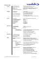
1
Connection
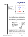
cables to the RS-232 IN (from ControlVIEW Xtreme or control
system) and RS-232 OUT (to the next Vaddio VISCA controlled
camera product in the control chain. A closure pair (voltage
sensing) is also provided to control the opening of the WallVIEW
50i PTZ HideAway independent of the IR remote controller
provided with the system. To take advantage of this feature, an
additional two-conductor cable is a requirement (see Figure 4).
Figure 4:
Cat. 5 connections and
closure pair in camera
module (under camera)
POWER
VIDEO
Note: The closure pair
opens the WallVIEW
camera door when the
camera is off and has
power available ONLY.
The closure pair will not
raise the camera.
Camera
Mounting
Connection
RS-232
IN
RS-232
OUT
Closure Pair
(For limited use
only)
9. Using the four (4) ¼” x 2” supplied toggle screws, insert the
screws through the front of the mounting flange’s mounting
holes and secure the toggles to the screws but only turn two or
three threads. Verify that the toggles open toward the back of
the mounting flange. Carefully insert the camera module
backbox with attached cables into the drywall-mounting hole
aligning the toggle bolts and press firmly and completely into the
wall. Tighten the four mounting screws securely but do not over
tighten.
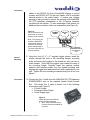
10. Connect the Cat. 5 cable from the WallVIEW 50i PTZ HideAway
POWER/VIDEO Jack to the supplied Vaddio Quick-Connect
Box. This single Cat. 5 cable is broken out to the following
connections (see Figure 5):
• S-Video Output
• Composite Video Output
• Power Supply Input
Figure 5:
Vaddio Quick-Connect Box for
power and video breakout
• Note: Rack mountable QuickConnect bracket is available as
an option.
WallVIEW 50i HideAway – Document 341-141 Rev. C
Page 5 of 14