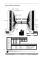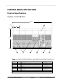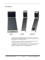
1
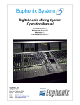
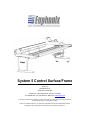
System 5 Control Surface/Frame
Version 1.0
Part# 840-07576-01
Publish date: October 1999
Euphonix Inc. 220 Portage Avenue Palo Alto , CA 94306
Tel: (650)855-0400 Fax: (650) 855-0410 Web Page: www.euphonix.com
In the interest of continued product development, Euphonix reserves the right to make improvements in this manual and the
product it describes at any time, without notice or obligation.
System 5, S-5, PatchNet, eMix, EuCon, R-1, Studio Hub, , Digital Studio Controller, DSC, CleaR, GainBall, SnapShot,
SnapShot Automation, SnapShot Recall and Total Automation are trademarks of Euphonix Inc.
TABLE OF CONTENTS
Box Inventory..............................................................................................................4
Safety and Precautions..............................................................................................4
Power On Sequence ............................................................................................................................5
CE/TUV/UL/CSA ..........................................................................................................5
Component Overview.................................................................................................6
Functional Description ........................................................................................................................6
FRAME SECTION ......................................................................................7
Physical Specifications .......................................................................................................................7
Exploded View ......................................................................................................................................7
Side Panel View ....................................................................................................................................8
Dimensions and Weight ......................................................................................................................9
User Reference - Frame ...........................................................................................10
Assembling the S5 Frame .................................................................................................................10
System 5 Ethernet/Power Cable Configuration ..............................................................................17
System 5 Ethernet Cable Harness....................................................................................................18
CONTROL MODULES SECTION.............................................................20
Physical Specifications............................................................................................20
Top View - Control Modules..............................................................................................................20
Filler Modules .....................................................................................................................................21
Dimensions and Weight ....................................................................................................................22
Technical Specifications..........................................................................................22
Environmental Requirements ...........................................................................................................22
Power Requirements .........................................................................................................................22
Power Consumption ..........................................................................................................................22
Control Module Expansion Port .......................................................................................................23
General Description........................................................................................................................23
Physical Pinout ...............................................................................................................................23
DB25 Electrical Specification: ........................................................................................................25
Typical Usage:................................................................................................................................25
Alternate Usage #1:........................................................................................................................26
Alternate Usage #2:........................................................................................................................27
User Reference – Control Modules .........................................................................28
Control Module Setup........................................................................................................................28
Overview of Ethernet IP Address Allocation...................................................................................28
Self Test Procedure for CM401, CM402 and CM408 .......................................................................29
Initiating Self Test ...........................................................................................................................30
Self Test Operations.......................................................................................................................31
Top Level Test Keys.......................................................................................................................32
LED test..........................................................................................................................................33
All Switch LEDs Toggle ..................................................................................................................34
Color Toggle ...................................................................................................................................34
All Switch and Indicator LEDs Toggle ............................................................................................34
Vegas Mode ...................................................................................................................................34
S5 Control Surface/Frame Manual
Page 2
Version 1.0 ©1999 Euphonix, Inc.
Switch Test .....................................................................................................................................35
Intelligent Display Test ...................................................................................................................36
Knob Test .......................................................................................................................................37
Knob value display .........................................................................................................................38
Halo Test ........................................................................................................................................38
Knob meter display.........................................................................................................................38
Knob switch test .............................................................................................................................38
Expansion port switch test..............................................................................................................38
Fader Test ......................................................................................................................................39
Fader Test (continued) ...................................................................................................................40
All fader up .....................................................................................................................................41
All fader down.................................................................................................................................41
Fader cycle test with speed control ................................................................................................41
Fader echo test...............................................................................................................................41
Touch Sense Test ..........................................................................................................................41
Backstop PFL switch test ...............................................................................................................41
Fader Write value display...............................................................................................................41
Fader Read value display...............................................................................................................41
TFT backlight brightness test .........................................................................................................41
CPU Test .............................................................................................................................................42
RAM Test........................................................................................................................................42
ROM Test .......................................................................................................................................42
PC104 RAM Test............................................................................................................................43
APPENDIX 1.............................................................................................45
Parts Lists .................................................................................................................45
System 5 Leg Set: Part# 946-07220-01 ........................................................................................45
System 5 Frame Set, 6ft: Part# 946-06425-01 .............................................................................47
System 5 Frame Set, 9ft: Part# 946-06840-01 .............................................................................48
System 5 Frame Set, 12ft: Part# 946-07160-01 ...........................................................................49
S5 Control Surface/Frame Manual
Page 3
Version 1.0 ©1999 Euphonix, Inc.
Box Inventory
Description
Part #
946-07220-01
S5 Leg Set
726-06398-01
Leg, Left, Finished
726-06419-01
Leg, Right, Finished
726-06415-01
Keyboard Tray Assembly
726-07216-01
Keyboard Palm Rest
840-07576-01
S5 Control Surface/Frame Manual
One of the following Frame Kits
946-06425-01
Frame, 6ft
946-06840-01
Frame, 9ft
946-07160-01
Frame, 12ft
The specified number of the following modules:
946-05718-01
CM401
946-05719-01
CM402
946-05717-01
CM408
946-07000-01
CM409-HTP
032-07169-00
Serial Mouse Extender
CM409-H
946-06650-01
CM409-F
946-06651-01
Qty
1
1
1
1
1
Safety and Precautions
1) Read Instructions - Read all the safety and operation instructions before operating the
System 5 Control Surface.
2) Heed Warnings – Follow all warnings on the Control Modules and in these operating
instructions.
3) Water and Moisture – Do not use the Control Surface near water.
4) Heat – Locate the Control Surface away from heat sources.
5) Power Sources – Connect the Control Modules only to a power supply of the type
described in these operation instructions or as marked on the Control Modules.
6) Power Cord Protection – Route power cords so that they are not likely to be walked
upon or pinched by items placed on them.
7) Object and Liquid Entry – Do not drop objects or spill liquids on the Control Surface.
8) Damage Requiring Service – The Control Modules should be serviced only by qualified
personnel when:
a) Objects have fallen, or liquid has spilled into the Control Modules; or
b) A Control Module does not appear to operate or exhibits a marked change in
performance; or,
c) A Control Module has been dropped or sustained other physical damage.
S5 Control Surface/Frame Manual
Page 4
Version 1.0 ©1999 Euphonix, Inc.
7)
Servicing – Do not attempt to service the Control Modules beyond those means
described in this operation manual. All other servicing should be referred to the
Euphonix Tech Support department.
8) Fuse replacement – To prevent electric shock and avoid risk of fire, replace fuse only
with the same type and rating.
9) To prevent electric shock, do not use the Control Modules polarized plug with an
extension cord, receptacle or other outlet unless the blades can be fully inserted to
prevent blade exposure.
10) Grounding or Polarization – Do not defeat the grounding or polarization of the Control
Modules.
Power On Sequence
The Control Surface modules are powered up by a switch on the back of the frame. The Control
Surface should be powered up after the Virtual Mixer is running.
CE/TUV/UL/CSA
CE documentation is available.
S5 Control Surface/Frame Manual
Page 5
Version 1.0 ©1999 Euphonix, Inc.
Component Overview
Functional Description
The System 5 Console consists of a frame and leg assemblies which house a configurable
number of Control Modules that comprise the Control Surface. The System 5 Control Surface is
the digital control center for all the System 5 component assemblies. The Control Surface
communicates with the System 5 component assemblies via Ethernet network connections.
Control signals are transmitted to the Euphonix EH224 EuCon Hub and distributed to the various
System 5 component assemblies. No audio passes through the Control Surface.
Available in 6 foot, 9 foot, and 12 foot frame widths, the System 5 Control Surface is modular
in construction. The number and variety of Control Modules are configurable based on the
specific needs of each facility. Control modules are 12 inches wide. Filler modules can be
ordered in full or half width.
S5 Control Surface/Frame Manual
Page 6
Version 1.0 ©1999 Euphonix, Inc.
FRAME SECTION
Physical Specifications
21
15
1
13
2
16
18
7
19
10
3
Exploded View
Item No.
Qty
Description
1
1
Leg, Right, Finished
2
2
Box beam
3
1
Leg, Left, Finished
7
1
Palm beam
10
4
Caster Brackets
13
1
Back beam-9
15
2
Brace 1
16
3
Cover, back, 3ft
18
1
Leg panel
19
1
Keyboard Tray Assy
21
1
CM401 assembly
21
*
CM402 assembly
21
*
CM408 assembly
21
*
CM409F assembly
21
*
CM409H assembly
* Qty depends on specified configuration
S5 Control Surface/Frame Manual
Part No. 6ft
726-06399-01
Part No. 9ft
726-06419-01
726-06437-01
726-06398-01
726-06415-01
Part No. 12ft
726-07164-01
726-06408-01
726-06430-01
726-07163-01
726-06404-01
726-06686-01 (1)
726-06686-01 (2)
726-06686-01 (3)
Left – 726-06394-01
Right – 726-06826-01
726-06415-01
946-05718-01
946-05719-01
946-05717-01
946-06651-01
946-06650-01
Page 7
Version 1.0 ©1999 Euphonix, Inc.
Side Panel View
41”
27
30.5”
13
21
6
7
15
16
2
39.5”
8
19
29.5”
2
18
24.2”
22
Item No.
Qty
Description
2
2
Box Beam
6
1
Plate, compression
7
2
Palm Beam
8
1
Plate, spread
12
4
Caster
13
1
Back beam
15
2
Brace
16
*
Cover, back, 3ft
18
2
Leg Panel
19
1
Keyboard Tray Assy
21
1
CM401 assembly
21
*
CM402 assembly
21
*
CM408 assembly
21
*
CM409F assembly
21
*
CM409H assembly
22
4
Foot, level
27
1
Talk Back Mic
* Qty depends on specified configuration
S5 Control Surface/Frame Manual
12
Part No. 6ft
726-06399-01
726-0403-01
726-06408-01
726-06411-01
726-06686-01 (2)
726-06394-01 (Left)
Page 8
Part No. 9ft
726-06437-01
726-06402-01
726-07168-01
726-06404-01
726-06407-01
726-06430-01
Part No. 12ft
726-07164-01
726-07162-01
726-07163-01
726-06686-01 (3)
726-06686-01 (4)
726-06826-01 (Right)
726-06415-01
946-05718-01
946-05719-01
946-05717-01
946-06651-01
946-06650-01
000-06434-00
302-07044-00
Version 1.0 ©1999 Euphonix, Inc.
Dimensions and Weight
Height: 39.5 inches
Width: Frame size + 10”
Depth: 41 inches
Weight: Frame without modules
6ft Frame:
245lbs (111kg)
9ft Frame:
300lbs (136kg)
12ft Frame:
380lbs (172kg)
Approximately 14 inches of depth should be left behind the System 5 Control Surface for
cable connections.
S5 Control Surface/Frame Manual
Page 9
Version 1.0 ©1999 Euphonix, Inc.
User Reference - Frame
Assembling the S5 Frame
Tools required:
•
•
•
•
•
•
•
Hex drivers, 1/8”, 3/16”, 7/32”, ¼”, 5/32”
Flat-bladed screwdriver, ¼”
Socket wrench, ½”
Silicon grease for bolts (Finish Line bicycle grease works great)
Aux leg (item 20, not shown on some frame drawings)
Bus wire, two 24” pieces
Tap set for 3/8” 24 (3/8” 16 for newer box beams) and 5/16 18 threads
Minimum number of people required: 2. For a 12-foot frame, 3 people are required.
Refer to the System 5 Frame drawings (pages 7-8) and the Parts Lists at the end of this
manual to help with parts identification and visualization of the steps set forth in this procedure.
1) Verify that all screws and bolts have been greased. If they aren’t greased, apply silicon grease to
all of them.
2) Start with inserting the middle box beam (item 2) in the left leg (item 3, Leg Left). You may have to
drop the leg panel (item 18, legpnl) to get it in easily. Two people need to hold up the beam,
while the third person holds up the leg. Guide the beam into the leg (flat side up). Insert a 3/8”
24x1.5 button head bolt (046-06421-00) with a 3/8” flat washer (081-07193-00) through the leg
hole and into the beam, being careful not to strip the threads. Tighten the bolt fully, using a
7/32” hex driver.
S5 Control Surface/Frame Manual
Page 10
Version 1.0 ©1999 Euphonix, Inc.
3) After the beam is attached to the leg, the auxiliary leg (12 ft frame only, item 20) can be put
underneath the beam near the center to hold it up. Secure the auxiliary leg to the beam by
inserting a “T” nut (000-06690-00) into the beam, and thread a 5/16x18x0.50 screw (044-0719200) through the auxiliary leg mounting hole and into the “T” nut.
4) Insert the rear box beam (item 2) into the left leg next, using the same techniques outlined in step
2. The auxiliary leg can help to hold up the beam.
S5 Control Surface/Frame Manual
Page 11
Version 1.0 ©1999 Euphonix, Inc.
5) Prior to inserting the palm beam (item 7) into the left leg, thread the bus wire through one of the
holes of the spread plate (part#726-06404-01, item 8), twist-locking the wire at the spread plate
end. Run the other end of the wire through its matching bolt hole on the left end of the palm
beam. The spread plate should mount inside the end of the palm beam, flat side up. As the
palm beam is inserted into the left leg (rounded side out) guide the bus wire into the matching
bolt hole of the leg. Insert a 3/8” 24x1.5 button head bolt through the leg hole and into the beam,
using the same techniques outlined in step 1. The auxiliary leg can help to hold up the beam.
6) Insert the back beam (item 13) into the left leg, using the same techniques outlined in step 1. The
S5 Control Surface/Frame Manual
Page 12
Version 1.0 ©1999 Euphonix, Inc.
auxiliary leg can help to hold up the beam.
7) Insert as many “T” nuts in the beams as required. For example, you will need 3 “T” nuts for the
middle box beam’s inner channel and 3 “T” nuts for the palm beam’s inner channel in order to
install the keyboard tray. You will need 4 “T” nuts for each back cover brace (item 15, brace 1),
2 for the back beam bottom channel and 2 for the rear box beam outside channel. You will need
2 “T” nuts for each power strip, usually mounted on the rear box beam.
8) With the auxiliary leg holding up one end of the S5 frame, insert the four beams into the right leg
(item 1, Leg Right), using the same techniques outlined in step 1. Also, for the palm beam, use
the same technique with the spread plate and bus wire as outlined in step 4.
9) Install the four box beam braces (item 4) on each end of the box beams. Use four 5/16-18x3.5
bolts (043-06688-00) and four 5/16 lock washers (082-066889-00) for each box beam brace.
Use a ½” socket wrench. Do not tighten down fully until the frame is fully loaded and its width is
S5 Control Surface/Frame Manual
Page 13
Version 1.0 ©1999 Euphonix, Inc.
checked.
10) To secure the spread plates into the palm beam ends, pull down on the bus wire, and line up the
spread plate screw holes with the leg screw holes. With a 3/16” hex driver, insert a 5/1618x1.125 flathead screw (046-06409-00) into spread plate screw hole sans the bus wire. Once
the screw is threaded in and tightened down, remove the bus wire and insert the other countersunk screw in the screw hole that the bus wire previously occupied. You may have to loosen the
other screw a little in order to remove the bus wire.
11) Using the 3/16” hex driver and 5/16-18x2.25 flathead screws (046-06401-00), install the spread
plates (part# 726-06402-01, items 5 & 6) into the back beam ends. (Like spread plate pictured
in Step 5.)
12) Install all the modules into the frame to ensure that their surfaces are flush. Use the
thumbscrews (936-07240-01, S5 thumbscrew kit, 4 per module) to secure the modules to the
box beams. Before installing the 401 module permanently into the frame, attach the talkback
mic bracket (936-07219-01, S5 talkback mic kit) into the middle top screw hole of the SBC panel,
using the screw and insulating washer supplied in the S5 talkback mic kit.
13) After verifying that the control surface is acceptable, tighten all loose screws and bolts in the
frame. Tighten the bolts on the box beam braces only until their lock washers flatten, and no
further. You will have to temporarily remove the modules on each end of the frame to be able to
tighten the box beam braces.
14) Using a ¼” hex driver and 5/16x18x0.375 socket head screws (044-06686-00), install the back
cover braces (item 15, brace 1). Determine the position of the braces by aligning them with the
back cover mounting screw holes. Move the slide nuts in the rear box beam and back beam to
the brace locations, and mount the braces to them.
S5 Control Surface/Frame Manual
Page 14
Version 1.0 ©1999 Euphonix, Inc.
15) Using a 5/32“ hex driver and 1/4x20/3/8 button head screws (044-07236-00), install the back
covers on the braces.
16) Determine where the power strips (part#600-07223-00)) are going to be mounted on the rear
box beam, line up the slide nuts in the box beam to match the mounting holes of the power
strips, and use a ¼” hex driver with 5/16x18x0.375 socket head screws to mount the power
strips into the slide nuts.
17) Determine where the keyboard drawer (item 19, kbd drawer) is going to be located, then line up
the slide nuts in both box beams (the distance between the screw holes on each box beam end
of the keyboard drawer is xx”). Use a ¼” hex driver with 5/16x18x0.375 socket head screws to
mount the drawer into the slide nuts.
S5 Control Surface/Frame Manual
Page 15
Version 1.0 ©1999 Euphonix, Inc.
18) If the network, power, and talkback mic cables are not going to enter the S5 frame from the
bottom of a leg, then the leg panel supporting the cabling will have to have its knockout plate
removed. Remove the leg panel from the leg before punching. The punch direction should be
from the outside to the inside. Support the knockout hole on the inside of the leg panel with a
roll of duct tape, or something similar. This will alleviate any distortion to the leg panel metal
while punching.
S5 Control Surface/Frame Manual
Page 16
Version 1.0 ©1999 Euphonix, Inc.
System 5 Ethernet/Power Cable Configuration
S5 Control Surface/Frame Manual
Page 17
Version 1.0 ©1999 Euphonix, Inc.
System 5 Ethernet Cable Harness
1
A1
(TYP 30 PLACES)
LABEL EACH CABLE AS INDICATED
(TYP BOTH ENDS)
1
2
2
3
3
5
4
(TYP 15 PLACES)
4
5
5
6
6
31.0'
A1-A15
7
7
8
8
9
9
10
10
SEE DETAIL 'A'
6
12
12
13
13
3
14
14
A15
A16-A30
11
11
2
A16
1
POINT B
4
15
A30
15
POINT A
3
2
B1
MACHINE ROOM
CONSOLE
B2
1.0' (x15)
(TYP BOTH ENDS)
LABEL CABLE AS INDICATED
(TYP BOTH ENDS)
CONNECTOR
MATING
A1-A16
A2-A17
A3-A18
A4-A19
A5-A20
A6-A21
A7-A22
A8-A23
A9-A24
A10-A25
A11-A26
A12-A27
A13-A28
A14-A29
A15-A30
B1-B2
5.0'
DETAIL 'A'
A1-A30 WIRE LIST
A1-A15
PIN 1
PIN 2
PIN 3
PIN 4
PIN 5
PIN 6
PIN 7
PIN 8
A16-A30
PIN 1
PIN 2
PIN 3
PIN 4
PIN 5
PIN 6
PIN 7
PIN 8
(TYP BOTH ENDS)
B1-B2 WIRE LIST
WIRE COLOR
WHT/ORG
ORG
WHT/GRN
BLU
WHT/BLU
GRN
WHT/BRN
BRN
B1
1
2
3
B2
1
2
3
WIRE
DRAIN
WHITE
BLACK
SIGNAL
GND
HOT
COLD
CABLE ASSEMBLY PARTS LIST
ITEM
1
2
3
4
5
6
QTY
30
1
1
41'
495'
31'
MFR
PHYCO
NEUTRIK
NEUTRIK
GEPCO
BELDEN
TECHFLEX
MFR P/N
1001-8P8CSR
NC3FX
NC3MX
MP1022 BLACK
MEDIA TWIST 350(1872A)BLUE
CCPT6X
DESCRIPTION
RJ45 PLUG, 8-8, RND SLD
XLR 3PIN FEMALE CABLE CONNECTOR
XLR 3PIN MALE CABLE CONNECTOR
2 LEAD SHIELDED CABLE, 24AWG
4 PAIR UTP CABLE, 24AWG SOLID COPPER
EXPANDABLE SLEEVING
Notes:
1. All dimensions are in feet
2. Make sure that all wire ends are flush with "Point A". Typical 30 places
3. Make sure that the insulation jacket of the cable reaches to "Point B" when crimping terminal. Typical 2 places. Cable ends are to be
terminated according toTIA/EIA 568b standards.
S5 Control Surface/Frame Manual
Page 18
Version 1.0 ©1999 Euphonix, Inc.
CONTROL MODULE SECTION
S5 Control Surface/Frame Manual
Page 19
Version 1.0 ©1999 Euphonix, Inc.
CONTROL MODULES SECTION
Physical Specifications
Top View - Control Modules
6’10”
5”
D
12”
41”
3
A
B
C
A
1
Frames are available in 6ft, 9ft, and 12ft sizes. Actual width of Control Surface is frame size + 10
inches.
Item No.
Qty
Description
A
*
CM408 Control Module
B
*
CM402 Control Module
C
1
CM401 Control Module
D
*
TFT Display
1
1
Leg, right
3
1
Leg, left
* Qty depends on specified configuration
S5 Control Surface/Frame Manual
Page 20
Part No.
946-05717-01
946-05719-01
946-05718-01
Inc. in CM Module
726-06419-01
726-06398-01
Version 1.0 ©1999 Euphonix, Inc.
Filler Modules
CM409F
CM409H
CM409HTP
CM409F- This is the full-wide blank module for S5 Control surfaces. It can be placed
anywhere within the control surface to fill up the frame. It provides a working surface for remote
controls, keyboards, etc. Order part# 946-06651-01.
CM409H- This module is a half-wide blank module for S5 Control surfaces. It module is
similar to a CM409F but only half the width. Order part# 946-06650-01.
CM409HTP- This module is a half-wide Track Panner. It is the same width as the CM409H.
The CM409HTP contains a high quality track ball for panning and two switches for Pan
Select/Punch and Channel Pan Function. Order part# 946-07000-01.
S5 Control Surface/Frame Manual
Page 21
Version 1.0 ©1999 Euphonix, Inc.
Dimensions and Weight
Module
CM401:
CM402:
CM408:
CM409F:
CM409H:
CM409HTP:
Weight
35lbs (16kg)
35lbs (16kg)
35lbs (16kg)
16lbs (7kg)
9lbs (4kg)
10lbs (4.5kg)
Width
12”
12”
12”
12”
6”
6”
Approximately 14 inches of depth should be left behind the System 5 Control Surface for
cable connections.
Technical Specifications
Environmental Requirements
Environmental requirements for the System 5 Control Modules are as follows:
Operating Temperature:
0 to 40 degrees Celsius (ambient)
Storage Temperature:
-10 to 55 degrees Celsius
Humidity:
0 to 90% non-condensing
Power Requirements
90 to 254 Volts AC (rms), 50/60Hz, 150 Watts per module.
Power Consumption
Power consumption of the Control Surface Modules is shown in the table below.
Module
CM401
CM402
CM408
Individual Module Power Consumption
US (117V)
Europe (230V)
1.0A
.5A
1.0A
.5A
1.0A
.5A
• Inrush current :
25 Amps
• Fuse Rating:
5Amp Slo-Blo or Time Delay
S5 Control Surface/Frame Manual
Page 22
Japan (100V)
1.0A
1.0A
1.0A
Version 1.0 ©1999 Euphonix, Inc.
Control Module Expansion Port
General Description
On the back of each System 5 Control Module (CM401, CM402, and CM408,) is a DB25
Euphonix Expansion Port. This port is a hardware interface to external devices, and supports 8
switch inputs and 8 LED/relay drive outputs. This document describes the pinout and typical
usage of this port.
Physical Pinout
The Expansion Port on the module is a DB25 female connector. A DB25 male cable needs
to be built to interface to this port (pictured below). The pinout has been configured for easy
interface to the Euphonix GP132 box, and is as shown on the following page:
S5 Control Surface/Frame Manual
Page 23
Version 1.0 ©1999 Euphonix, Inc.
Looking into the FEMALE connector on the module:
13
1
25
14
Looking into a MALE cable connector:
1
13
14
25
Pin #
1
2
3
4
5
6
7
8
9
10
11
12
13
14
15
16
17
18
19
20
21
22
23
24
25
S5 Control Surface/Frame Manual
Signal
LED 1 output (active low)
Switch 1 input (active high)
+5V
LED 3 output (active low)
Switch 3 input (active high)
+5V
LED 5 output (active low)
Switch 5 input (active high)
+5V
LED 7 output (active low)
Switch 7 input (active high)
+5V
+5V
+5V
LED 2 output (active low)
Switch 2 input (active high)
+5V
LED 4 output (active low)
Switch 4 input (active high)
+5V
LED 6 output (active low)
Switch 6 input (active high)
+5V
LED 8 output (active low)
Switch 8 input (active high)
Page 24
Version 1.0 ©1999 Euphonix, Inc.
DB25 Electrical Specification:
The +5V output on the connector is protected internally by a 200mA self-resetting fuse. If
LED drive outputs are used, it is recommended that several +5V connections be used to drive
the anodes of the LED’s (at least one +5V wire per LED used). The active-low LED drive
outputs are current limited by internal 110 ohm series resistors, and are capable of sinking 20mA
each. The active-high switch inputs are TTL-level inputs with 100K pull-down resistors.
Typical Usage:
Currently, the software supports remote talkback switching and status on Switch inputs 1-4
and LED outputs 1-4 on the CM401 Expansion Port only. Functionality is as follows:
Function
Triggered by
Status shown on
Talkback à Mon A
Switch 1 input
(momentary)
LED 1 output
Talkback à Mon B
Switch 2 input
(momentary)
LED 2 output
Talkback à Mon C
Switch 3 input
(momentary)
LED 3 output
Talkback à Mon D
Switch 4 input
(momentary)
LED 4 output
For example, while Switch 1 is pressed down, the Talkback mic signal will be routed to the
Mon A output, and LED 1 will light during the time that the switch is pressed down. Also, if
Talkback à Mon A is activated from the console itself, LED 1 will also light, to indicate the
status.
Pressing SW1A routes the Talkback signal to Mon A, and the SW1B LED lights to indicate
the TalkbackàMon A status.
PINS 3, 6, 9, 12, 13, 14, 17, 20, 23 (PICK ANY 4)
+5V
4 3
6
SW1A
4 3
SW1B
6
SW2A
4 3
SW2B
LIGHTED SWITCH
6
SW3A
4 3
SW3B
LIGHTED SWITCH
6
SW4A
SW4B
LIGHTED SWITCH
LIGHTED SWITCH
1 2
5
1 2
5
1 2
5
1 2
5
PIN 2
PIN 1
PIN 16
PIN 15
PIN 5
PIN 4
PIN 19
PIN 18
S5 Control Surface/Frame Manual
Page 25
Version 1.0 ©1999 Euphonix, Inc.
Alternate Usage #1:
Another way of using these talkback inputs/outputs would be to have one switch activate
more than one talkback function. For example, a single switch can route the Talkback signal to
all four monitor outputs:
PINS 3, 6, 9, 12, 13, 14, 17, 20, 23 (PICK ANY 4)
+5V
4 3
SW1A
D1
D2
LED
D3
LED
LED
D4
LED
1 2
PINS 2, 16, 5, 19
PIN 1
PIN 15
PIN 4
PIN 18
Pushing SW1A routes the Talkback signal to all four monitor outputs, and LED’s D1-D4
indicate the Talkback à Mon A-D status.
S5 Control Surface/Frame Manual
Page 26
Version 1.0 ©1999 Euphonix, Inc.
Alternate Usage #2:
Another implementation combines the above two approaches – we have individual Talkback
enable buttons like in the Typical Usage, but we’ve added an ‘OMNI’ switch that routes the
Talkback signal to all four monitor outputs:
PINS 3, 6, 9, 12, 13, 14, 17, 20, 23 (PICK ANY 4)
+5V
4 3
4 3
6
SW1A
4 3
SW1B
6
SW2A
4 3
SW2B
6
SW3A
4 3
SW3B
LIGHTED SWITCH
LIGHTED SWITCH
6
SW4A
SW1A
SW4B
LIGHTED SWITCH
LIGHTED SWITCH
1 2
1 2
5
1 2
PIN 1
5
1 2
PIN 15
5
1 2
5
PIN 18
PIN 4
D1
D2
1N4148
D3
1N4148
D4
1N4148
1N4148
PIN 2
S5 Control Surface/Frame Manual
PIN 16
PIN 5
Page 27
PIN 19
Version 1.0 ©1999 Euphonix, Inc.
User Reference – Control Modules
Control Module Setup
Overview of Ethernet IP Address Allocation
Computer
System Computer
Digital Pilot
Interface Pilot
IP Address
192.168.0.1
192.168.0.200
192.168.0.201
192.168.0.202
192.168.0.203
192.168.0.215
Module
CM401
CM402
CM408
S5 Control Surface/Frame Manual
Computers
Pilot ID
N/A
1
2
3
4
15
Frame ID
N/A
N/A
N/A
N/A
N/A
N/A
Control Modules
IP Address
Frame ID
192.168.0.24
IL
192.168.0.25
IL
192.168.0.10
IL
192.168.0.11
IL
192.168.0.12
IL
192.168.0.13
IL
192.168.0.14
IL
192.168.0.15
IL
192.168.0.16
IL
192.168.0.17
IL
192.168.0.18
IL
Page 28
Module ID
0
1
2
3
15
Module ID
15
16
1
2
3
4
5
6
7
8
9
Version 1.0 ©1999 Euphonix, Inc.
Self Test Procedure for CM401, CM402 and CM408
(For CM40x Firmware Rev 1.0S)
The following pages describe the operation of standalone self test software for System-5
control modules.
The self-test code is designed to be invoked in a module right after power-up and before the
SBC downloads code into the control module 386 board.
The self-test works in a fully assembled module as well as with just the upper board or just
the lower board connected to the CPU board. However, the upper board must be present to run
fader test modes.
All the three types of control modules have the same lower board. Because of this, the lower
board can be tested separately without an upper board connected. The self-test can be invoked
from the lower board knobs as well as upper board self test keys.
S5 Control Surface/Frame Manual
Page 29
Version 1.0 ©1999 Euphonix, Inc.
Initiating Self Test
Enter self-test by pressing the self-test enter keys shown below. This must be done before
the SBC code download. If code download from the SBC happens during self-test, then the
module will automatically exit self-test and execute downloaded code.
Enter Self-Test
Press both Knob Switches
Enter Self-Test
Press both keys
GpSL
GpSL
NonB
Gp SL
NonB
GpSL
NonB
GpSL
NonB
Gp SL
NonB
GpSL
NonB
NonB
9
Rec 10
Rec
11
Rec 12
Rec 13
Rec
14
Rec 15
Rec
Rec 17
1
Rec 18
Rec 19
Rec 20
Rec 21
Rec 22
Rec 23
Rec 24
Rec25
Rec 26
Rec 27
Rec 28
Rec 29
Rec 30
Rec 31
Rec 32
Rec 33
Rec 34
Rec 35
Rec 36
Rec 37
Rec 38
Rec 39
Rec 40
Rec 41
Rec 42
Rec 43
Rec 44
Rec 45
Rec 46
Rec 47
Rec 48
Rec
GpSL
NonB
Rec
A
2
3
Rec
B
Rec
C
4
Rec
D
Record Machine
5
Rec
E
F
All
Repro
All
Input
6
Rec
7
Rec
G
Boom
Boom
Boom
Boom
Boom
Boom
2
Boom
4
Rec
H
Record
Safe
6
J
Rec
Ready
R-1
Boom
8
K
Grp
Route
Pan
M
Mix
Route
N
P
Flts
Q
R
S
Pan to:
Pan to:
Grp Buses Mix Buses
Route to
Sections
Ins
16
Gp SL
Btyp
NonB
Brng
Boom
Btrm
Mon D
Source
Mon C
Source
Reverse
Route
Dyn
EQ
Mon B
Source
PanR
PanR
Pa n R
PanR
PanR
Pa n R
PanR
PanR
Su r r
Su r r
Surr
Su r r
Su r r
Surr
Su r r
Su r r
1
3
5
78
F1tp
F1 F
F2 F
F2tp
Pa n R
At y p
Surr
Ar n g
Mon A
Source
Assign Knobs
DivF
DivF
DivF
DivF
DivF
DivF
DivF
DivF
Au x
In
Dyn
In
Clarinet
Slct/Pnch
cfg
xDpt
P1
xHys
Knob Values
cDpt
P2
P3
P4
P5
LoQ
cGMU
flts
In
EQ
In
Slct/Pnch
Store P
L4
L3
L2
L1
T2
T1
cfg
lmQ
hmQ
HiQ
At r m
DivF
FocF
FocF
FocF
FocF
FocF
FocF
FocF
xAtk
xRls
cAtk
cRls
LoF
lmF
hmF
HiF
FocF
Dly
Pa n F
PanF
PanF
Pa n F
Pa n F
PanF
Pa n F
Pa n F
xRat
xThr
cRat
cThr
LoG
lmG
hmG
HiG
PanF
Inpt
CR
Output
LR phase
L
FocF
Solo
Ctrl
Comms
Ctrl
Li
C Ri R
Sl Sr B
CR
Source
Main
Spkrs
Alt 1
Spkrs
Control Room
Dim
cfg
cpy
pst
cfg
cpy
pst
cfg
cpy
pst
cfg
cpy
pst
cfg
cpy
pst
cfg
cpy
pst
cfg
cpy
pst
cfg
cpy
*
*
Insrt In
Input
Input
Dyn In
Aux
Aux
Pan to:
Aux
Pan to:
Pan
Aux
Pan to:
Pan
route
M
I
X
G
R
P
route
swap
G
R
P
route
swap
G
R
P
route
swap
G
R
P
On
solo
route
swap
G
R
P
On
route
swap
G
R
P
Name
On
Name
On
solo
Name
Name
On
solo
On
solo
Name
On
solo
Name
Name
Name
Name
On
solo
Name
On
solo
Name
route
swap
Listen
Name
On
On
On
On
On
On
On
solo
solo
solo
solo
solo
solo
solo
Slate / Osc
ON
Input
Grp
Mstrs
Dyn
Mix
Mstrs
Dyn In
solo
Name
On
Name
Aux
route
swap
Name
On
solo
Pan
G
R
P
Name
On
Pan to:
M
I
X
Comms Talk
Aux
Mstrs
*
Name
solo
Info
EQ In
EQ
Filts
Filts In
Pan
M
I
X
Name
solo
Filts
Pan to:
Pan
M
I
X
cfg
pst
Name
On
solo
Name
EQ
Aux
Pan to:
Pan
M
I
X
Name
On
solo
Filts In
Aux
Pan to:
Pan
M
I
X
Name
On
solo
Dyn
Filts
Filts In
Aux
Pan to:
Pan
M
I
X
Name
On
solo
Name
On
solo
Num
G
R
P
Name
On
solo
EQ In
EQ
Filts
Filts In
Name
On
solo
Insrt In
Dyn In
Dyn
EQ In
EQ
Filts
Filts In
Name
On
solo
Input
Dyn In
Dyn
EQ In
EQ
Filts
Filts In
*
Insrt In
Input
Dyn In
Dyn
EQ In
EQ
Filts
Filts In
Insrt In
Input
Dyn In
Dyn
EQ In
EQ
Filts
Filts In
*
Insrt In
Input
Dyn In
Dyn
EQ In
EQ
Filts
*
Insrt In
Input
Dyn In
Dyn
EQ In
EQ
*
Insrt In
Input
Dyn In
Dyn
EQ In
Filts In
*
Insrt In
cfg
cpy
pst
Name
*
Insrt In
Main
Panel
Alt 2
Spkrs
Cut
On
solo
Strp
Slv
Name
On
solo
Grp
On
Cpy
Name
On
solo
Solo
Name
On
solo
Pst
swap
swap
swap
swap
Aux
Pan to:
solo
Pan
ALL
Strip
s
Scroll
Page
swap
Name
On
solo
Clr
M
I
X
swap
swap
mstrs
swap
swap
G
R
P
route
swap
M
I
X
swap
Center Strip
Mix
On
Pass
View
Input
Dyn
Save
Mix
Time
Display
hr
swap
select
swap
select
swap
select
swap
select
swap
select
swap
select
swap
select
swap
select
swap
select
swap
select
swap
select
swap
select
swap
select
swap
select
swap
select
swap
select
swap
select
main
select
Name
main
select
Name
main
select
Name
main
select
Name
main
select
Name
main
select
Name
main
select
Name
main
select
Name
chan
select
Name
chan
select
Name
chan
select
Name
chan
select
Name
chan
select
Name
chan
select
Name
chan
select
Name
chan
select
Name
main
select
Name
MS
S LL
M
solo
MM S
S LL
solo
MM S
S LL
solo
MS
S LL
M
solo
MS
S LL
M
solo
MM S
S LL
solo
MS
S LL
M
solo
M
MS
S LL
solo
MM S
S LL
solo
M S
M
S LL
solo
MM S
S LL
solo
MS
S LL
M
solo
M S
M
S LL
solo
MS
S LL
M
solo
MM S
S LL
solo
MS
S LL
M
solo
MM S
S LL
solo
I
II
min
bar
sec / ft
beat
fr / ms
tick
Isolate
Route
ON
ON
ON
ON
ON
ON
ON
ON
ON
ON
ON
ON
ON
ON
ON
ON
ON
ON
EQ
Read
-
+
=
Edit
Aux
Write
Abs
7
8
9
Cue
Write
Trim
4
5
6
3
ON
Fader
Grand
Master
x
x
x
x
x
x
x
Strips Only
12
12
12
12
12
12
12
12
12
12
12
12
12
12
12
6
6
6
6
6
6
6
6
6
6
6
6
6
6
6
6
6
0
0
0
0
0
0
0
0
0
0
0
0
0
0
0
0
0
12
6
6
6
6
6
6
6
6
6
6
6
6
6
6
6
6
6
18
12
12
12
12
12
12
12
12
12
12
12
12
12
12
12
12
12
24
0 18
0 18
0 18
0 18
0 18
0 18
0 18
0 18
0 18
0 18
0 18
0 18
0 18
0 18
0 18
0 18
0 18
30
24
24
24
24
24
24
24
24
24
24
24
24
24
24
24
24
24
36
30
30
30
30
30
30
30
30
30
30
30
30
30
30
30
30
30
36
42
48
60
72
36
42
48
60
72
36
42
48
60
72
36
42
48
60
72
36
42
48
60
72
36
42
48
60
72
36
42
48
60
72
36
42
48
60
72
36
42
48
60
72
36
42
48
60
72
36
42
48
60
72
36
42
48
60
72
36
42
48
60
72
36
42
48
60
72
36
42
48
60
72
36
42
48
60
72
36
42
48
60
72
S5 Control Surface/Frame Manual
Trim
+
Locate
Reg’s
Store
Curren
t
Store
Locate
Recall
-
0
12
6
CM402
Trim
Pan
x
12
CM408
locate time
All
Filts
Keys
Preview
Glide
On
1
2
Move
Punch
ATO
On
0
.
Clear
Enter
42
Select
Start
Select
End
Hold
On
48
54
60
72
84
Fill
<--
Fill
-->
Fill to
Punch
Undo
Redo
Pass
Record
Shuttle
Loc
Trim
Reh
Jog
Roll
Back
Return
Auto
Punch
Rec
CM401
Page 30
Version 1.0 ©1999 Euphonix, Inc.
Self Test Operations
The operation of each key on the upper and lower board is described in this document.
GpSL
Gp SL
NonB
GpSL
NonB
Gp SL
NonB
GpSL
NonB
GpSL
NonB
Gp SL
NonB
NonB
9
Rec 10
Rec
11
Rec 12
Rec 13
Rec
14
Rec 15
Rec
Rec 17
Rec 18
Rec 19
Rec 20
Rec 21
Rec 22
Rec 23
Rec 24
Rec25
Rec 26
Rec 27
Rec 28
Rec 29
Rec 30
Rec 31
Rec 32
Rec 33
Rec 34
Rec 35
Rec 36
Rec 37
Rec 38
Rec 39
Rec 40
Rec 41
Rec 42
Rec 43
Rec 44
Rec 45
Rec 46
Rec 47
Rec 48
1
Rec
GpSL
NonB
Rec
A
2
3
Rec
B
Rec
C
4
Rec
D
Record Machine
5
Rec
E
F
All
Repro
All
Input
6
Rec
7
Rec
G
8
Rec
H
Record
Safe
J
Rec
Ready
R-1
K
Grp
Route
M
Mix
Route
N
P
Q
R
S
Pan to:
Pan to:
Grp Buses Mix Buses
Route to
Sections
16
GpSL
Btyp
NonB
Brng
Mon D
Source
Mon C
Source
Reverse
Route
Boom
2
4
6
Pan
Flts
Ins
Dyn
EQ
Boom
Btrm
PanR
PanR
1
3
5
78
F1tp
F1 F
F2 F
F2tp
PanR
At y p
Surr
Surr
Surr
Ar n g
Boom
Boom
Boom
Boom
Boom
Boom
Boom
PanR
PanR
PanR
PanR
PanR
PanR
Surr
Surr
Surr
Surr
Surr
Surr
Mon B
Source
Mon A
Source
Assign Knobs
DivF
DivF
DivF
DivF
DivF
DivF
DivF
xDpt
DivF
Au x
In
Dyn
In
P1
xHys
flts
Clarinet
Slct/Pnch
cfg
Knob Values
P2
P3
P4
P5
In
Slct/Pnch
Store P
cDpt
cGMU
L4
L3
L2
L1
T2
T1
cfg
EQ
LoQ
lmQ
In
hmQ
HiQ
DivF
At r m
LR phase
L
FocF
FocF
FocF
FocF
FocF
FocF
FocF
FocF
xAtk
xRls
cAtk
cRls
LoF
lmF
hmF
HiF
FocF
Dly
PanF
PanF
PanF
PanF
PanF
PanF
PanF
PanF
xRat
xThr
cRat
cThr
LoG
lmG
hmG
HiG
PanF
Inpt
Solo
Ctrl
Comms
Ctrl
Li
C Ri R
CR
Output
Sl Sr B
CR
Source
Main
Spkrs
Alt 1
Spkrs
Control Room
Dim
cfg
cpy
pst
cfg
cpy
pst
cfg
cpy
pst
cfg
cpy
pst
cfg
cpy
pst
cfg
cpy
pst
cfg
cpy
pst
cfg
cpy
Insrt In
*
Insrt In
Input
Insrt In
Input
Dyn In
Aux
Input
Input
route
M
I
X
G
R
P
route
swap
M
I
X
G
R
P
route
swap
M
I
X
G
R
P
Aux
route
swap
M
I
X
G
R
P
route
swap
route
swap
Name
On
On
solo
solo
Name
Name
Name
Name
Filts
Name
Name
Name
Name
Name
route
swap
Listen
Name
Name
On
On
On
On
On
On
On
On
solo
solo
solo
solo
solo
solo
solo
solo
Slate / Osc
Input
Grp
Mstrs
Dyn
Mix
Mstrs
EQ In
EQ
Filts
Filts In
Name
Aux
Pan to:
G
R
P
route
swap
Name
Name
Name
Strp
Slv
Name
On
Solo
Cpy
Name
Pst
Name
swap
swap
swap
Pan
ALL
Strip
s
Scroll
Page
swap
Aux
Pan to:
solo
solo
Clr
M
I
X
swap
Name
On
On
On
solo
solo
solo
solo
solo
Grp
On
On
On
On
On
solo
Pan
M
I
X
Talk
Aux
Mstrs
*
Dyn In
solo
solo
solo
Name
On
On
On
On
solo
solo
solo
solo
Name
On
On
On
On
solo
Name
Comms
Info
ON
Insrt In
Name
cfg
pst
Name
On
solo
Name
EQ
Pan
G
R
P
Name
On
solo
Dyn
Aux
M
I
X
Name
On
solo
Input
Pan to:
Pan
G
R
P
Name
On
solo
Filts In
Aux
Pan to:
M
I
X
Name
On
solo
Num
G
R
P
Name
On
solo
EQ In
Filts
Filts In
Pan
*
Dyn In
Dyn
EQ
Filts
Pan to:
Insrt In
EQ In
EQ
Filts In
Pan
*
Dyn In
Dyn
Filts
Pan to:
Pan
Insrt In
EQ In
EQ
Aux
Pan to:
Pan
*
Dyn In
Dyn
Filts In
Aux
Pan to:
Pan
Input
Filts
Filts In
Aux
Pan to:
Insrt In
EQ In
EQ
Filts
Filts In
*
Dyn In
Dyn
EQ In
EQ
Filts
Filts In
Insrt In
Dyn In
Dyn
EQ In
EQ
Filts
*
Input
Dyn In
Dyn
EQ In
EQ
Filts In
Insrt In
Input
Dyn In
Dyn
EQ In
*
cfg
cpy
pst
Name
*
Main
Panel
Alt 2
Spkrs
Cut
swap
swap
mstrs
swap
swap
G
R
P
route
swap
M
I
X
swap
Center Strip
Mix
On
Pass
View
Save
Mix
Time
Display
hr
swap
select
swap
select
swap
select
swap
select
swap
select
swap
select
swap
select
swap
select
swap
select
swap
select
swap
select
swap
select
swap
select
swap
select
swap
select
swap
select
swap
select
main
select
Name
main
select
Name
main
select
Name
main
select
Name
main
select
Name
main
select
Name
main
select
Name
main
select
Name
chan
select
Name
chan
select
Name
chan
select
Name
chan
select
Name
chan
select
Name
chan
select
Name
chan
select
Name
chan
select
Name
main
select
Name
MM S
S LL
solo
MS
M
S LL
solo
MS
M
S LL
solo
MM S
S LL
solo
MS
M
S LL
solo
MS
M
S LL
solo
MS
M
S LL
solo
M
MS
S LL
solo
MS
M
S LL
solo
M S
M
S LL
solo
MM S
S LL
solo
S LL
MM S
solo
MS
S L
M
L
solo
MM S
S LL
solo
MS
S L
M
L
solo
MM S
S LL
solo
MM S
S LL
solo
I
II
Input
min
bar
Dyn
sec / ft
beat
fr / ms
tick
Isolate
Route
ON
ON
ON
ON
ON
ON
ON
ON
ON
ON
ON
ON
ON
ON
ON
ON
ON
ON
EQ
All
Filts
Keys
Read
-
+
=
Edit
Aux
Write
Abs
7
8
9
Cue
Write
Trim
4
5
6
3
ON
Fader
Grand
Master
x
x
x
x
x
x
x
Strips Only
12
12
12
12
12
12
12
12
12
12
12
12
12
12
12
12
6
6
6
6
6
6
6
6
6
6
6
6
6
6
6
6
6
6
0
0
0
0
0
0
0
0
0
0
0
0
0
0
0
0
0
12
6
6
6
6
6
6
6
6
6
6
6
6
6
6
6
6
6
18
12
12
12
12
12
12
12
12
12
12
12
12
12
12
12
12
12
24
0 18
0 18
0 18
0 18
0 18
0 18
0 18
0 18
0 18
0 18
0 18
0 18
0 18
0 18
0 18
0 18
0 18
30
24
24
24
24
24
24
24
24
24
24
24
24
24
24
24
24
24
36
30
30
30
30
30
30
30
30
30
30
30
30
30
30
30
30
30
36
42
48
60
72
36
42
48
60
72
36
42
48
60
72
36
42
48
60
72
36
42
48
60
72
36
42
48
60
72
36
42
48
60
72
36
42
48
60
72
36
42
48
60
72
36
42
48
60
72
36
42
48
60
72
36
42
48
60
72
36
42
48
60
72
36
42
48
60
72
36
42
48
60
72
36
42
48
60
72
36
42
48
60
72
S5 Control Surface/Frame Manual
Trim
+
Locate
Reg’s
Store
Locate
Recall
-
0
Preview
Glide
On
1
2
Move
Punch
ATO
On
0
.
Clear
Enter
42
Select
Start
Select
End
Hold
On
48
54
60
72
84
Fill
<--
Fill
-->
Fill to
Punch
Undo
Redo
Pass
Record
Shuttle
Loc
Trim
Reh
Jog
Roll
Back
Return
Auto
Punch
Rec
CM401
CM402
Upper Board
Test Keys
Trim
Store
Curren
t
Pan
x
12
CM408
locate time
Lower Board
Test Keys
Page 31
Version 1.0 ©1999 Euphonix, Inc.
Top Level Test Keys
To enter the 6 different tests, use the keys shown below. After entering the test, use the
detailed description of each test on the following pages to navigate through different test modes
within a test.
CPU Board tests
cpy
cfg
CPU
test
pst
LED test
*
Knob
test
Switch
test
LED
test
Display
test
Exit
Test
Fader
test
Switch Test
Insrt In
Input
Display Test
Dyn In
Dyn
On
On
On
On
solo
solo
solo
solo
Num
Grp
Slv
Strp
On
Solo
C
Knob Test
EQ In
EQ
Filts
Filts In
CM402
Fader Test
Aux
Exit Test /Exit to
main
Pan to:
Pan
CM401/CM408
LoF
LoQ
Knob Test
LED Test
LoF
LoQ
All LEDs
Toggle
Halo LEDs
Cycle Test
LoF
LoQ
Press Together
to Exit Test/Exit
to top-level
tests
Lower Board
S5 Control Surface/Frame Manual
Page 32
Version 1.0 ©1999 Euphonix, Inc.
LED test
The LED test has the following modes;
• Toggle upper board LEDs
• Toggle all LEDs
• LED color test
• Vegas mode
All Switch LEDs
toggle
All Upper
LEDS
toggle
*
Color Toggle
Color
toggle
Input
Dyn
EQ
All Switch and Indicator
LEDs toggle
Vegas Mode/Vegas
Mode fader cycle
toggle
Num
Aux
Pan
All Upper
& Lower
LEDs
toggle
swap
Exit Test Key/Exit to
main
Grp
Slv
swap
Exit
Test
Vegas
Mode
Strp
On
Solo
swap
CM402
CM401/CM408
LoF
LoQ
LED Color
Toggle Test
LoF
LoQ
All LEDs
Toggle
Halo LEDs
Cycle Test
LoF
LoQ
Press Together
to Exit Test/Exit
to top-level
tests
Lower Board
S5 Control Surface/Frame Manual
Page 33
Version 1.0 ©1999 Euphonix, Inc.
All Switch LEDs Toggle
This switch toggles all the upper board LEDs on and off. This mode times out after 5 mins if
all LEDs are left ON and goes into Vegas mode.
Color Toggle
This switch cycles between the same color LEDs in the following order
• Green
• Red
• Yellow
• Orange
• Blue
All Switch and Indicator LEDs Toggle
This toggles all the upper and lower board LEDs including the daughter board LEDs.
NOTE: For thermal reasons, the module should not be left with all LEDs On. Use Vegas
mode for burn-in. For protection, the module will time out into Vegas mode if all LEDs are left ON
for more than 5 minutes.
Vegas Mode
Flashes alternate LEDs on and off. The default Vegas mode also puts the fader into cycle
test. Repeated presses of this key toggles the fader cycle on/off. If left running, the fader cycle
will time out after 5 minutes.
S5 Control Surface/Frame Manual
Page 34
Version 1.0 ©1999 Euphonix, Inc.
Switch Test
Switch test has the following modes;
Momentary switch press - This tests lights up the switch LED of a switch while it is pressed.
*
Input
Dyn
EQ
Aux
Exit Test
Key/Exit to main
Pan
CM402/CM408
Exit Test
Num
Grp
swap
Strp
Slv
swap
On
Solo
swap
Cpy
Pst
swap
CM402
S5 Control Surface/Frame Manual
Page 35
Version 1.0 ©1999 Euphonix, Inc.
Intelligent Display Test
Display bit test – This test lights up the whole of the intelligent display. It dims the displays
for the duration of this test to protect them from overheating and burnout.
Display text - This test shows a text on each intelligent display, which happens to be the
hexadecimal display number in the software map.
This test is not accessible from the lower board.
Display bits test
*
Display text test
Input
Dyn
EQ
Aux
Exit Test
Key/Exit to main
Pan
CM402/CM408
Display
Bits Test
Exit Test
Display
Text Test
Num
Grp
swap
Strp
Slv
swap
On
Solo
swap
Cpy
Pst
swap
CM402
S5 Control Surface/Frame Manual
Page 36
Version 1.0 ©1999 Euphonix, Inc.
Knob Test
• Halo Test
• Knob value display
• Knob meter display
• Knob switch test
• Expansion port switch test
*
Input
Knob Halo
Test/Halo Test
Setup
Knob
Knob
Halo
Meters
test Knob Display
Value
Display
Knob Meters
Display
Exit
Test
Knob Test
Dyn
Num
EQ
Aux
Pan
swap
Exit Test Key/Exit to
main
Grp
Slv
swap
Strp
On
Solo
swap
CM402
CM401/CM408
LoF
LoQ
LoF
LoQ
Knob Test
Halo LEDs
Cycle Test/LED
Cycle Step
LoF
LoQ
Press Together
to Exit Test/Exit
to top-level
tests
Lower Board
S5 Control Surface/Frame Manual
Page 37
Version 1.0 ©1999 Euphonix, Inc.
Knob value display
Displays the hex 0 through FF value of the knob being currently moved on an intelligent
display. This mode is useful for testing the CM401 spin knob.
Halo Test
This cycles through all the knob halo and center LEDs by turning one LED on at a time on
each key press.
Knob meter display
Shows the knob value as a bar on the meter board (fader daughter board).
Knob switch test
All the knobs halo orange LEDs light up while the knob center switch is pressed. The
Expansion port switches are also tested in this mode. Pressing one of the eight switches will light
up its LED for as long as the key is pressed.
Expansion port switch test
See the Knob switch test section.
S5 Control Surface/Frame Manual
Page 38
Version 1.0 ©1999 Euphonix, Inc.
Fader Test
• All fader up
• All fader down
• Fader cycle test with speed control
• Fader echo test
• Touch Sense Test
• Backstop PFL switch test
• Fader Write value display
• Fader Read value display
• TFT backlight brightness test
This test is not accessible from the lower board.
All Fader Up
*
All Fader Down
Input
Fader Cycle
Dyn
EQ
Fader Echo
Aux
Pan
Exit Test Key/Exit to
main
CM401/CM408
All
Fader
Up
Fader
Cycle
All
Fader
Down
Num
swap
Grp
Exit
Test
Fader
Echo
Strp
Slv
swap
On
swap
Solo
Cpy
Pst
swap
CM402
S5 Control Surface/Frame Manual
Page 39
Version 1.0 ©1999 Euphonix, Inc.
Fader Test (continued)
Fader Cycle
Speed
GpSL
GpSL
NonB
GpSL
NonB
GpSL
NonB
GpSL
NonB
GpSL
NonB
GpSL
NonB
NonB
9
Rec 10
Rec
11
Rec 12
Rec 13
Rec
14
Rec 15
Rec
Rec 17
1
Rec 18
Rec 19
Rec 20
Rec 21
Rec 22
Rec 23
Rec 24
Rec25
Rec 26
Rec 27
Rec 28
Rec 29
Rec 30
Rec 31
Rec 32
Rec 33
Rec 34
Rec 35
Rec 36
Rec 37
Rec 38
Rec 39
Rec 40
Rec 41
Rec 42
Rec 43
Rec 44
Rec 45
Rec 46
Rec 47
Rec 48
Rec
GpSL
NonB
Rec
A
2
3
Rec
B
Rec
C
4
Rec
D
Record Machine
5
Rec
E
F
All
Repro
All
Input
6
Rec
7
Rec
G
8
Rec
H
Record
Safe
J
Rec
Ready
R-1
K
Grp
Route
M
Mix
Route
N
P
Q
R
S
Pan to:
Pan to:
Grp Buses Mix Buses
Route to
Sections
16
GpSL
Btyp
NonB
Brng
Mon D
Source
Mon C
Source
Reverse
Route
Boom
Boom
Boom
Boom
Boom
Boom
Boom
Boom
2
4
6
Pan
Flts
Ins
Dyn
EQ
Boom
Btrm
PanR
PanR
PanR
PanR
PanR
PanR
PanR
PanR
1
3
5
78
F1tp
F1 F
F2 F
F2tp
PanR
At y p
Mon B
Source
Mon A
Source
Surr
Surr
Surr
Surr
Surr
Surr
Surr
Surr
Assign Knobs
DivF
DivF
DivF
DivF
DivF
DivF
DivF
DivF
Au x
In
Dyn
In
xDpt
P1
xHys
Knob Values
Clarinet
Slct/Pnch
cfg
cDpt
P2
P3
P4
P5
LoQ
cGMU
flts
In
EQ
In
Slct/Pnch
Store P
Surr
Ar n g
DivF
At r m
L4
L3
L2
L1
T2
T1
cfg
lmQ
hmQ
HiQ
FocF
FocF
FocF
FocF
FocF
FocF
FocF
xAtk
xRls
cAtk
cRls
LoF
lmF
hmF
HiF
FocF
Dly
PanF
PanF
PanF
PanF
PanF
PanF
PanF
PanF
xRat
xThr
cRat
cThr
LoG
lmG
hmG
HiG
PanF
Inpt
CR
Output
LR phase
L
FocF
Solo
Ctrl
Comms
Ctrl
Li
C Ri R
Sl Sr B
CR
Source
Main
Spkrs
Alt 1
Spkrs
Control Room
Dim
cfg
cpy
pst
cfg
cpy
pst
cfg
cpy
pst
cfg
cpy
pst
cfg
cpy
pst
cfg
cpy
pst
cfg
cpy
pst
cfg
cpy
Insrt In
Insrt In
Input
*
*
Insrt In
Input
Dyn In
Input
Dyn In
Filts In
Filts In
Aux
Aux
Pan to:
Aux
Pan to:
Pan
route
M
I
X
G
R
P
route
swap
swap
select
M
I
X
G
R
P
route
swap
swap
select
G
R
P
route
swap
swap
select
G
R
P
route
swap
swap
select
G
R
P
route
swap
swap
select
G
R
P
On
solo
On
Name
Name
On
Name
On
solo
Name
On
solo
On
solo
Name
Name
Name
Name
On
solo
Name
Name
Name
On
solo
Name
On
solo
Name
Listen
Name
On
On
On
On
On
On
On
solo
solo
solo
solo
solo
solo
solo
Slate / Osc
ON
Insrt In
Input
Grp
Mstrs
Dyn
Mix
Mstrs
Dyn In
solo
Name
On
solo
Name
Aux
G
R
P
On
route
swap
swap
select
Comms Talk
Aux
Mstrs
*
EQ In
EQ
Filts
Filts In
Name
Name
On
solo
Pan
M
I
X
cfg
pst
Info
Cut
Name
On
solo
solo
Filts
Pan to:
route
swap
swap
select
Name
On
solo
Name
EQ
Pan
M
I
X
Name
On
solo
Dyn
Pan to:
Pan
M
I
X
Name
On
solo
Input
Aux
Pan to:
Pan
M
I
X
Name
On
solo
Filts In
Aux
Pan to:
Pan
M
I
X
Name
On
solo
Name
On
solo
Num
G
R
P
Name
On
solo
EQ In
Filts
Filts In
Aux
Pan to:
Pan
*
Dyn In
Dyn
EQ
Filts In
Aux
Pan to:
Pan
Input
Filts
Filts In
Insrt In
EQ In
EQ
Filts
Filts In
*
Dyn In
Dyn
EQ In
EQ
Filts
Filts In
Input
Dyn
EQ In
EQ
Filts
Insrt In
Dyn In
Dyn
EQ In
EQ
Filts
*
Insrt In
Dyn In
Dyn
EQ In
EQ
Filts
*
Input
Dyn In
Dyn
EQ In
EQ
Insrt In
Input
Dyn In
Dyn
EQ In
Insrt In
*
cfg
cpy
pst
Name
*
Main
Panel
Alt 2
Spkrs
On
solo
Strp
Slv
Name
On
solo
Grp
On
Cpy
Name
On
solo
Solo
Name
swap
swap
select
swap
swap
select
swap
swap
select
swap
solo
Pan
ALL
Strip
s
Scroll
swap
swap
select
Aux
Pan to:
On
solo
Clr
Page
swap
swap
select
Name
On
solo
Pst
M
I
X
swap
select
swap
mstrs
swap
swap
select
swap
G
R
P
route
swap
swap
select
swap
select
M
I
X
swap
Center Strip
Mix
On
Pass
View
Input
Dyn
Save
Mix
Time
Display
hr
swap
select
I
II
min
bar
sec / ft
beat
fr / ms
tick
Isolate
main
select
Name
MS
S LL
M
solo
main
select
Name
S LL
MM S
solo
main
select
Name
S L
MM S
L
solo
main
select
Name
MS
S LL
M
solo
main
select
Name
MS
S LL
M
solo
main
select
Name
S L
MM S
L
solo
main
select
Name
MS
S LL
M
solo
main
select
Name
M
MS
S LL
solo
chan
select
Name
S L
MM S
L
solo
chan
select
Name
M S
S LL
M
solo
chan
select
Name
S L
MM S
L
solo
chan
select
Name
MS
S LL
M
solo
chan
select
Name
M S
S L
M
L
solo
chan
select
Name
MS
S LL
M
solo
chan
select
Name
S L
MM S
L
solo
chan
select
Name
MS
S LL
M
solo
main
select
Name
S L
MM S
L
solo
Route
ON
ON
ON
ON
ON
ON
ON
ON
ON
ON
ON
ON
ON
ON
ON
ON
ON
ON
EQ
All
Keys Filts
Read
-
+
=
Edit
Aux
Write
Abs
7
8
9
Cue
Write
Trim
4
5
6
3
ON
Fader
Grand
Master
x
x
x
x
x
x
x
locate time
Trim
+
Locate
Reg’s
Store
Locate
Recall
-
Pan
x
Strips Only
0
12
12
12
12
12
12
12
12
12
12
12
12
12
12
12
12
12
6
6
6
6
6
6
6
6
6
6
6
6
6
6
6
6
6
6
0
0
0
0
0
0
0
0
0
0
0
0
0
0
0
0
0
12
6
6
6
6
6
6
6
6
6
6
6
6
6
6
6
6
6
18
Preview
Glide
On
1
2
Move
Punch
ATO
On
0
.
Clear
Enter
12
12
12
12
12
12
12
12
12
12
12
12
12
12
12
12
12
24
0 18
0 18
0 18
0 18
0 18
0 18
0 18
0 18
0 18
0 18
0 18
0 18
0 18
0 18
0 18
0 18
0 18
30
24
24
24
24
24
24
24
24
24
24
24
24
24
24
24
24
24
36
30
30
30
30
30
30
30
30
30
30
30
30
30
30
30
30
30
42
Select
Start
Select
End
Hold
On
36
42
48
60
72
36
42
48
60
72
36
42
48
60
72
36
42
48
60
72
36
42
48
60
72
36
42
48
60
72
36
42
48
60
72
36
42
48
60
72
36
42
48
60
72
36
42
48
60
72
36
42
48
60
72
36
42
48
60
72
36
42
48
60
72
36
42
48
60
72
36
42
48
60
72
36
42
48
60
72
36
42
48
60
72
48
54
60
72
84
Fill
<--
Fill
-->
Fill to
Punch
Undo
Redo
Pass
Record
Shuttle
Loc
Trim
Reh
Jog
LED
Auto
Punch
Rec
solo
MS
S LL
M
Touch Sense
Return
Roll
Back
Backstop
PFL switch
LED
Fader Read/Write Value Display
Upper Display = Read Value
Lower Display = Write Value
Trim
Store
Curren
t
ON
12
6
0
6
S5 Control Surface/Frame Manual
Page 40
Version 1.0 ©1999 Euphonix, Inc.
All fader up
All faders all the way up
All fader down
All faders all the way down
Fader cycle test with speed control
All faders cycle up and down at the speed determined by the speed control knob. The speed
control knob also varies the brightness of the TFT backlight when in this test. It should vary from
all the way off to the brightest setting. This fader cycle test times out after 5 minutes to protect
the faders from burn-out.
Fader echo test
All faders follow the one fader touched.
Touch Sense Test
Self-test touch sense LED lights up when a fader is touched. This mode is always active in
fader test mode.
Backstop PFL switch test
Self test backstop PFL LED lights up when a fader is pulled back to enable its backstop PFL
switch. This mode is always active in fader test mode.
Fader Write value display
Any value written to a fader is displayed in its designated fader write intelligent display. This
mode is always active in fader test mode.
Fader Read value display
All faders are continuously read and the read value is displayed in its designated fader read
intelligent display. This mode is always active in fader test mode.
TFT backlight brightness test
See Fader cycle test.
S5 Control Surface/Frame Manual
Page 41
Version 1.0 ©1999 Euphonix, Inc.
CPU Test
RAM Test
This tests the upper unused portion of the CPU board RAM. Watch for the ‘Pass’ display to
show up when the test is done.
ROM Test
This test reads the ROM and computes and checksum and displays it. The user/tester can
match the checksum to a known good checksum to make sure ROM test is successful.
Checksum (version 1.0S):
CM401
996C
CM402
33ae
CM408
C38e
S5 Control Surface/Frame Manual
Page 42
Version 1.0 ©1999 Euphonix, Inc.
PC104 RAM Test
This test writes and reads the whole PC104 RAM and checks for errors. Watch for the ‘Pass’
display to show up when the test is done.
S5 Control Surface/Frame Manual
Page 43
Version 1.0 ©1999 Euphonix, Inc.
RAM Test
*
ROM Test
Input
PC104 RAM Test
Dyn
EQ
Aux
Exit Test Key/Exit
to main
Pan
CM401/CM408
RAM
Test
PC104
RAM Test
Exit
Test
ROM
Test
Num
swap
Grp
Slv
Strp
swap
On
swap
Solo
Cpy
Pst
swap
CM402
S5 Control Surface/Frame Manual
Page 44
Version 1.0 ©1999 Euphonix, Inc.
APPENDIX 1
Parts Lists
System 5 Leg Set: Part# 946-07220-01
Item#
Item Description
Qty
726-06398-01
726-06846-01
726-06394-01
726-06415-01
726-06493-01
041-06290-00
726-06791-01
000-06790-00
420-04065-00
600-06387-00
600-00728-00
110-05551-00
726-06419-01
726-06847-01
726-06826-01
042-05677-00
048-00929-00
046-06073-00
726-06405-01
06406-01
726-06407-01
726-06838-01
044-06686-00
081-06417-00
726-06832-01
000-06434-00
600-06991-00
030-06993-01
030-06994-01
030-06995-01
030-06996-01
030-06997-01
030-06998-01
030-06999-01
006-04969-00
049-00838-00
032-07207-00
030-07199-01
Leg-Left-Finished S5
Leg-Left-Machined S5
Panel-Weldment-Left Leg
Keyboard Tray Assy
Track-Keyboard Top S5
10x32x1/4 Pan/Phil/Cz
Track-Keyboard Base S5
Glide-Keyboard S5
Dpdt-20a Rocker
Iec320/C14 Power Entry
Line Filter/Am
Coupler Rj45 Panel Mount
Leg-Right-Finished S5
Leg-Right-Machined S5
Panel-Weldment-Right
6-32x3/16 Flat/Phil/Clrznc
6-32x3/8 Pan/Phil/Sem-Ext/Clr
4-40x1/4l Pan/Phl/Clr Zinc
Bracket-Rear Caster
Bracket-Front Caster
Caster-36mm
Spacer-Left-S5 Cm
5/16-18x.375 Bolt Socket
#10 Flat Washer-Brass
Ac Cover S5
Leveling Pad-5/16-18
Iec320/C13 Power Outlet
Ca-Ac Line-S5 Frame
Ca-Ac Neutral-S5 Frame
Ca-Ac Gnd-S5 Frame
Ca-Outlet Ac Line-S5 Frame
Ca-Outlet Ac Neutral-S5
Ca-Sw Line-S5 Frame
Ca-Sw Neutral-S5 Frame
Label-Universal Ground
6-32 Kepnut/Ext/Clr Zinc
Ca-Pwr/Iec/N-Usa/8ft/15a
Ca-Door Support-S5
1
1
1
1
1
8
1
2
1
1
1
12
1
1
1
14
4
4
2
2
4
1
8
2
2
4
3
1
1
5
1
1
1
1
1
12
1
4
S5 Control Surface/Frame Manual
Page 45
Version 1.0 ©1999 Euphonix, Inc.
Parts List (cont)
000-07194-00
044-06686-00
041-07074-00
041-00917-00
002-07316-00
726-07216-01
084-00939-00
046-07331-00
S5 Control Surface/Frame Manual
1.5" Grommet
5/16-18x.375 Bolt Socket
10-24x3/8l Pan/Phil/Cz
10-32x.125l Skt/Shldr/Ss
Cable-Strap
Kbd Palmrest-S5
#10 Washer Ext Star/Clr Zinc
10-32x3/8 Button/Skt/Ss
Page 46
1
8
16
8
1.6
1
8
8
Version 1.0 ©1999 Euphonix, Inc.
Parts List (cont)
System 5 Frame Set, 6ft: Part# 946-06425-01
Item#
Item Description
Qty
726-06399-01
726-06400-01
726-06408-01
726-06402-01
726-06403-01
726-06404-01
726-06411-01
726-06686-01
600-07223-00
032-07147-00
032-07148-00
032-07149-00
032-07150-00
081-07193-00
936-07218-01
043-06688-00
082-06689-00
046-06401-00
046-06421-00
081-07193-00
936-07241-01
044-07236-00
936-07239-01
000-06690-00
044-06686-00
936-07240-01
040-06833-00
030-07394-01
Beam-Box 6ft S5
Clamp-Beam
Beam-Back 6ft S5
Plate-Back Beam
Palm Rest-6ft S5
Plate-Palm Beam
Brace-Back
Cover-Back 3ft
Power Strip-Iec320-6pos
Iec320 Jumper Cordset-0.5m
Iec320 Jumper Cordset-1.0m
Iec320 Jumper Cordset-1.5m
Iec320 Jumper Cordset-2.5m
3/8 Flat/Wash/Ss
S5 Frame Bolt Kit
5/16-18x3.5 Bolt Hex-Head-Zi
5/16 Lockwasher
5/16-18x2.25 Bolt Flat/Soc/Ss
3/8-16x1.25l Buttonhd/Skt/Ss
3/8 Flat/Wash/Ss
S5 Rear Panel Bolt Kit
¼-20x3/8 B4cs
S5 Tee Hardware Kit
5/16-18x.375 Tee Nut/Cz
5/16-18x.375 Bolt Socket Hd/Cz
S5 Thumb Screw Kit
10-32x3/8 Thumb\Washer Face
Ca-Internal Ethernet/6ft
2
4
1
2
1
2
1
2
2
5
3
2
1
8
1
16
16
8
8
8
1
20
1
22
22
7
4
1
S5 Control Surface/Frame Manual
Page 47
Version 1.0 ©1999 Euphonix, Inc.
Parts List (cont)
System 5 Frame Set, 9ft: Part# 946-06840-01
Item#
Item Description
Qty
726-06437-01
726-06400-01
726-06439-01
726-06402-01
726-07168-01
726-06404-01
726-06411-01
726-06686-01
600-07223-00
032-07147-00
032-07148-00
032-07149-00
032-07150-00
030-07180-01
936-07218-01
043-06688-00
082-06689-00
046-06401-00
046-06421-00
081-07193-00
936-07241-01
044-07236-00
936-07239-01
000-06690-00
044-06686-00
936-07240-01
040-06833-00
Beam-Box 9ft S5
Clamp-Beam
Beam-Back 9ft S5
Plate-Back Beam
Palm Rest-9ft S5
Plate-Palm Beam
Brace-Back
Cover-Back 3ft
Power Strip-Iec320-Reworked
Iec320 Jumper Cordset-0.5m
Iec320 Jumper Cordset-1.0m
Iec320 Jumper Cordset-1.5m
Iec320 Jumper Cordset-2.5m
Ca-Internal Ethernet/9ft
S5 Frame Bolt Kit
5/16-18x3.5 Bolt Hex-Head-Zi
5/16 Lockwasher
5/16-18x2.25 Bolt Flat/Soc/Ss
3/8-16x1.25l Buttonhd/Skt/Ss
3/8 Flat/Wash/Ss
S5 Rear Panel Bolt Kit
¼-20x3/8 B4cs
S5 Tee Hardware Kit
5/16-18x.375 Tee Nut/Cz
5/16-18x.375 Bolt Socket Hd/Cz
S5 Thumb Screw Kit
10-32x3/8 Thumb\Washer Face
2
4
1
2
1
2
2
3
2
5
3
2
1
1
1
16
16
8
8
8
1
20
1
22
22
10
4
S5 Control Surface/Frame Manual
Page 48
Version 1.0 ©1999 Euphonix, Inc.
Parts List (cont)
System 5 Frame Set, 12ft: Part# 946-07160-01
Item#
Item Description
Qty
726-07164-01
726-06400-01
726-07163-01
726-06402-01
726-07162-01
726-06404-01
726-06411-01
726-06686-01
600-07223-00
032-07147-00
032-07148-00
032-07149-00
032-07150-00
936-07218-00
043-06688-00
082-06689-00
046-06401-00
046-06421-00
081-07193-00
936-07241-01
044-07236-00
936-07239-01
000-06690-00
044-06686-00
936-07240-01
040-06833-00
936-07237-01
726-06416-01
000-06434-00
000-06690-00
044-07192-00
030-07395-01
Beam-Box-12ft S5
Clamp-Beam
Beam-Back-12ft S5
Plate-Back Beam
Palm Rest-12ft S5
Plate-Palm Beam
Brace-Back
Cover-Back 3ft
Power Strip-Iec320-6pos
Iec320 Jumper Cordset-0.5m
Iec320 Jumper Cordset-1.0m
Iec320 Jumper Cordset-1.5m
Iec320 Jumper Cordset-2.5m
S5 Frame Bolt Kit
5/16-18x3.5 Bolt Hex-Head-Zi
5/16 Lockwasher
5/16-18x2.25 Bolt Flat/Soc/Ss
3/8-16x1.25l Buttonhd/Skt/Ss
3/8 Flat/Wash/Ss
S5 Rear Panel Bolt Kit
1/4-20x3/8 B4cs
S5 Tee Hardware Kit
5/16-18x.375 Tee Nut/Cz
5/16-18x.375 Bolt Socket Hd/Cz
S5 Thumb Screw Kit
10-32x3/8 Thumb\Washer Face
S5 Aux Leg Kit
Leg-Auxiliary S5
Leveling Pad-5/16-18
5/16-18x.375 Tee Nut/Cz
5/16-18x.50 Bolt Socket Hd
Ca-Internal Ethernet/12ft
2
4
1
2
1
2
3
4
3
5
3
2
1
1
16
16
8
8
8
1
20
1
22
22
13
4
1
1
2
8
8
1
S5 Control Surface/Frame Manual
Page 49
Version 1.0 ©1999 Euphonix, Inc.