1
CHAPTER 5: Operation
5. Operation
This chapter explains how to operate the ServSwitch Duo/Quadro. Please read this
chapter carefully before starting to use a Duo/Quadro.
5.1 Controls and Indicators
The ServSwitch Duo/Quadro has several external user controls and indicators that
might be useful when you operate it. On the left end of its rear panel, you’ll see a
two-position DIP switch. Position 1 of this switch is reserved for future use, while
Position 2 is used for firmware upgrades (see Section 5.20).
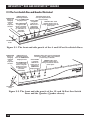
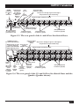
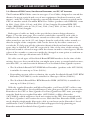
On the front panel, there are two pushbuttons paired with 7-segment LEDs. One
of these button/LED pairs is labeled USER, and the other is labeled COMPUTER:
• The green USER 7-segment LED shows which user’s current computer selection
or connection status is shown in the red COMPUTER 7-segment LED(s). (The
4- and 8-Port Duo models have a single COMPUTER LED; the 12- and 16-port
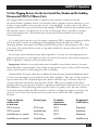
Duo models and the Quadro have dual COMPUTER LEDs.) The functions of
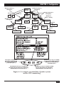
the COMPUTER LED(s) are shown in Figure 5-1 on the next page.
• Press the USER button to switch to the next user in numeric sequence and
display their computer selection.
• Press the COMPUTER button to switch the currently selected user to the next
available computer port in numeric sequence. Which port qualifies as the
“next available computer port” will depend on whether the Duo/Quadro is
cascaded, which computers you have access to (if security is enabled), etc.
There are two special channels that you can select with the COMPUTER
button. These are the on-screen menu channel “o” and the nonexistent
channel “0” (zero). Selecting the on-screen menu channel will cause the onscreen menu or the login window to be displayed on your monitor. Selecting
channel zero will disable the video, keyboard, and mouse at your user station.
These channels are provided as convenient “parking places” for user ports that
are not currently in operation.
The Duo/Quadro also has several regular (single-dot) LEDs on its front panels.
Two are labeled “POWER A” and “POWER B”; they light steadily when the Duo/
Quadro is receiving proper power through the corresponding power inlet (see
Section 3.5 for more information). The others are labeled “ACTIVITY”; the Duo
has two labeled “ACTIVITY 1” and “ACTIVITY 2,” while the Quadro has four
labeled “ACTIVITY 1” through “ACTIVITY 4.” They flash when the Duo/Quadro
receives keyboard or mouse data from the corresponding user port—thus
confirming that the user-station keyboards and mice are working.
51