1
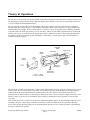
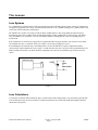
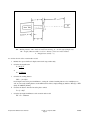
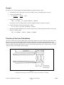
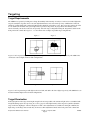
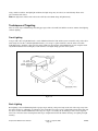
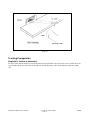
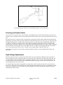
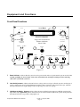
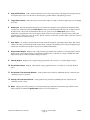
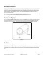
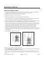
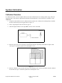
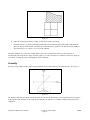
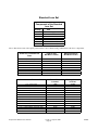
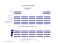
Model 5100 Displacement Follower Non-Contact Single Axis Tracking System Diversified Optronix Corp. 116 Quirk Road Milford, CT 06460 www.divop.com Table of Contents Introduction, 1 Equipment Supplied, 1 Warnings, 1 System Assembly, 2 Theory of Operation, 3 The Lenses, 5 Lens Systems, 5 Lens Calculations, 5 Precision of the Lens Calculations, 7 Targeting, 9 Target Requirements, 9 Target Illumination, 9 Techniques of Targeting, 10 Tracking Prerequisites, 11 Focusing and System Noise, 12 High-Voltage Adjustments, 12 Equipment and Functions, 13 Front Panel Functions, 13 Model 806 Optical Head, 15 Tracking Axis Alignment, 15 Rear Panel, 15 Operating Procedures, 16 General Operating Procedure, 16 Velocity and Acceleration Measurement, 17 Calibration, 20 System Noise, 20 Common Problems, 21 System Calibration, 22 Calibration Procedure, 22 Linearity, 23 Standard Lens Set, 24 Lens Calibration Data Sheet, 25 Appendix, 26 Introduction The 5100 Displacement Follower is a non-contact, real-time motion measurement instrument that solves measurement problems where other instruments fail. It can measure the displacement of remote or inaccessible objects. The camera tracks the motion of the target and provides an analog output proportional to displacement. Custom optics allow a range in the field of view from 0.05” up to several feet. Equipment Supplied One Model 5100 Control Unit One Model 806B Tracking Head One 10’ Interconnecting Cable One Storage/Carrying Case One Standard Lens Set Warnings High Voltage The tracking head and its power supply contain voltages dangerous to human life. These voltages are not accessible during normal operation, but when the cover is removed from either the tracking head or control unit, these voltages are accessible and dangerous. Photomultiplier The tracking tube used in the 5000 Series Displacement Followers is susceptible to damage if subjected to high intensity light. Using the unit outdoors in bright sunshine without stopping down the lens would be an example of use in high intensity light. When changing a lens, avoid direct exposure of the photo tube to intense light sources. If the photo tube should become paralyzed, store the complete tracking head in a dark room for several days. Unless the overexposure has been extreme, the tube will regain its sensitivity. Cable Connections Although the system has been equipped with circuitry to protect it against internal damage, disconnecting the optical head from the control unit while AC power is applied can produce dangerously high voltage on the housing of the optical head. Optical Head Important! Always remove ac power from the system before attempting to disconnect the optical head. Displacement Follower User’s Manual Version 1.4, April 19, 2004 Page 1 IM1008 System Assembly 1 Inspect the equipment for damage that might have occurred during shipment. If you find any damage, notify the shipping company immediately. 2 Attach the interconnecting cable from the control unit to the optical head and secure with the lock ring. 3 Attach the lens systems to the optical head. The lens screws into the extension barrel, and the extension barrel screws into the head. The thread system in the head is a standard Leica, 39mm diameter. Note that the 105mm lens comes attached to the 72mm extension tube. The 72mm extension is factory set and should come set to the correct length. 4 Connect the control unit to a 100-120 VAC, 50/60 Hz power source. Displacement Follower User’s Manual Version 1.4, April 19, 2004 Page 2 IM1008 Theory of Operation The system is a non-contacting electro-optical displacement follower designed to track the motion of a target along any axis. The moving target under study must show a sharp discontinuity in the intensity of its reflected or emitted light. The tracker is, in fact, locking onto that light/dark interface. The lens system focuses the image of the discontinuity onto the photo cathode of an image dissector tube. A simplified drawing of this tube is shown in Figure 1. The backside of the photo cathode emits electrons at a level proportional to the intensity of the projected light. These electrons are then accelerated to refocus on an aperture plate containing a small hole or aperture. This converts the optical image to an electron image, with an electron density proportional to the original light intensity of the target. As electrons enter the small aperture, they are amplified to produce a current output proportional to the number of electrons entering the aperture. Moving the electron image across the aperture plate varies the number of electrons entering the aperture. Figure 1 The system detects change in the photo tube’s output current, and through a servo loop, causes the electron image to refocus on the aperture. The servo loop circuit re-centers the electron image by passing current through coils creating a magnetic field that deflects the electron beam back to its original position. Since the current needed for deflection is directly proportional to the distance that the electron image has moved from center, it acts as a measure of displacement. The actual interface (target) can be moved over the diameter of the aperture by adjusting the reference potential, or lock-on, in the servo loop. If the electron image moves so that fewer electrons are admitted through the aperture, the photo-multiplier output decreases and changes the servo control voltage so that the electron image returns to its original locked-on position. If the image moves in the opposite direction, letting more electrons through the aperture, the servo control is polarized, again returning the image to its locked-on position. Displacement Follower User’s Manual Version 1.4, April 19, 2004 Page 3 IM1008 There are two possible target configurations for measuring target displacement along the vertical axis: light over dark and dark over light. That means it must be possible to alter the phase of the current going through the deflection coils to deflect the electron image back to its original locked-on position and not away from this center position. In the 5000 Series, the target switch on the front panel of the control unit changes the phase. See Figure 2. Failure to set this switch to the target configuration being tracked will cause improper deflection and render the system inoperative. Figure 2 Displacement Follower User’s Manual Version 1.4, April 19, 2004 Page 4 IM1008 The Lenses Lens Systems To accommodate the working distances and measurement ranges that individual applications may require, the standard lens set supplied is appropriate for a variety of situations. Included in the set are a 105mm enlarging lens, a 50mm variable-focus camera lens, and five different extension tubes. The 105mm lens is capable of focusing at fourteen unique working distances and corresponding measurement ranges depending upon how it is assembled on the tracking head with the possible combinations of extension tubes. The 50mm lens, used with the same extensions, can focus at an infinite number of working distances and corresponding ranges of measurement. If the standard lens set cannot meet an application’s requirements, DE can supply alternative lens systems to meet almost any standards. Feel free to consult the factory for assistance in selecting an appropriate system. In determining the measurement range and working distance for the 105 mm lens in varying configurations with the extension tubes and the 105mm lens, refer to Figure 3 and the Standard Lens Sheet on page 24. Keep in mind that the total displacement that the tracker is to follow should be comparable to the full scale measurement range for the chosen lens system. Figure 3 Lens Calculations A few simple calculations will determine the proper extension barrel and working distance associated with a particular fullscale measurement range. Please note that these calculations yield theoretical results which will differ slightly from those obtained in actual practice. Displacement Follower User’s Manual Version 1.4, April 19, 2004 Page 5 IM1008 Figure 4 WD = Working Distance, MR = Full scale Measurement Range, fl = Focal Length of Simple Lens, EX = Length of Extension Tube needed, D = Distance from lens to Photo Cathode, A = Magnification (usually < 1) To calculate the size of the extension tube needed: 1 Estimate the expected full-scale displacement for the target under study 2 Calculate the magnification A = 0.15 in MR in or A = 3.775 mm MR mm 3 Calculate the working distance WD = (1+1/A) fl Focal length is most often given in millimeters, causing the calculated working distance to be in millimeters as well. To convert the working distance from millimeters into inches, simply multiply by 0.03937: WD (in.) = WD (mm) X 0.03937 (in/mm) 4 Calculate the distance from the lens to the photo cathode D = (1 + A) fl 5 Calculate the length in millimeters of the extension tube needed EX = D - 34.6 mm Displacement Follower User’s Manual Version 1.4, April 19, 2004 Page 6 IM1008 Example The lens to be used in this example is the 105mm enlarging lens supplied with the system. 1 Assume that the object under study is expected to exhibit a peak-to-peak displacement of one inch. 2 Calculate the magnification: A = 0.15 in. = MR in 3 0.15 in = 0.15 1 in Calculate the working distance, WD = (1 + 1/A) fl = (1 + 1/0.15) X 105 mm = 805 mm If you prefer to have the working distance in inches, multiply by 0.03937 to obtain 31.69 inches. 4 Calculate the distance from the lens to the photo cathode. D = (1 + A) fl = (1 + 0.15) X 105 mm = 121 mm 5 Calculate the length in millimeters of the extension tube needed by subtracting the internal distance between the photo tube and the faceplate. EX = D - 34.6mm = 121mm - 35.6mm = 86.4mm Precision of the Lens Calculations Often, the calculated values for the working distance and the tube length do not correlate well with experimental results. There are many reasons for this, ranging from the tolerances built into the lens and tubes during manufacture to the limitations of the simple lens formulas used in the calculation. Even the best lens has a finite thickness and is mounted in some way within a lens holder. Most single-focus lenses are made up of more than one piece of glass; the pieces of glass combine to make one lens with the rated focal length. Figure 5 A simplified drawing of the 105mm lens used in the previous numerical example. Displacement Follower User’s Manual Version 1.4, April 19, 2004 Page 7 IM1008 Figure 5 shows that the equivalent 105mm lens cannot be considered to be located exactly at the end of the extension tube. Its equivalent position is, in fact, approximately 13mm further along the optical axis than the position used in the calculations. This positioning of the lens in its diaphragm varies with different manufacturers and no one rule will solve the problem. It is best simply to estimate where the plane of the lens might be located on the lens holder and measure the distance from that point to the point of attachment of the lens holder to any extension barrels used. This distance should now be included in the length calculated for the extension barrel. Applying this to the example above, the actual barrel length to be used would be (86.4mm-13mm) or approximately 73mm. Working distances and full-scale measurement ranges have been calculated for the 105mm and the 50mm variable-focus lenses. For convenience, these values have been put into a table on the Standard Lens Sheet on page 24 . Note Since the values in the table are obtained by experiment, not from theoretical calculations, they are more realistic for actual set-up than calculated values would be. Displacement Follower User’s Manual Version 1.4, April 19, 2004 Page 8 IM1008 Targeting Target Requirements The 5000 Series operates by locking onto a sharp discontinuity in the intensity of an object’s reflected or emitted light. The target is actually the edge that can be seen at the light-dark interface and can be made up of any combination of reflected, absorbed, or emitted light. The contrast in light intensities should be at least three to one. The greater the contrast, the easier it is to obtain lock-on and the less system output noise is produced. In general, any target whose discontinuity can be observed visually can also be tracked electro-optically. Select the target configuration using the Target Phase switch on the front panel of the control unit. Figures 6, 7, 8 and 9 show some examples of possible target configurations. Figure 6 Figure 7 Figures 6 and 7 represent targets with configurations: of light over dark and dark over light, respectively. The 5000 Series can measure vertical displacement for both configurations. Figure 8 Figure 9 Figures 8 and 9 represent targets with light to the left of dark, and dark to the left of light, respectively. The 5000 Series can measure horizontal displacement for both configurations. Target Illumination If the light portion of the target is not bright enough, lock-on is not possible. The amount of light can be read with the builtin light measuring system. See Operating Procedures, page 16. If the light intensity of the target is beyond the adjustable range of the lens diaphragm—either too bright or too dim—other adjustments are available. For low light conditions, the high voltage to the image dissector tube may be increased. This adjustment is made on the back panel of the control unit Displacement Follower User’s Manual Version 1.4, April 19, 2004 Page 9 IM1008 using a small screwdriver. For high light conditions, the high voltage may be reduced, or neutral density filters can be placed in front of the lenses. Note The light source must be DC or the tracker will detect the 60 Hz change in light intensity. Techniques of Targeting There are many ways of illuminating and setting up targets. This section will deal with the two most common: front lighting and back lighting. Front Lighting A target with a discrete light/dark interface can be illuminated from the front and the system can track it easily. If the object under study does not have a built-in light/dark interface, you can tape or paint an interface onto the surface. The white light/dark interface should be a flat, non-gloss surface. Make sure the intensity of the illumination is great enough to mask any 60 Hz modulation from room lights, or turn down the room lights during operation of the system. Figure 10 Back Lighting Back lighting is best for illuminating dark or opaque targets. Placing a low-power lamp on the side of the target away from the tracker produces a collimating or a silhouette effect. It might be necessary to place a light diffuser between the lamp and the object to assure uniform illumination of the target. See Figure 10. Usually, the back-lit target offers a better signal-tonoise ratio, and easier tracker focusing than other target configurations and has the further advantage of requiring less light intensity. Displacement Follower User’s Manual Version 1.4, April 19, 2004 Page 10 IM1008 Figure 11 Tracking Prerequisites Single Axis, Vertical or Horizontal The target and its motion should be located in the plane that is perpendicular to the optical axis. For successful lock-on, the target’s width must be greater than 10% of the full-scale measurement range, and its location must be along the tracking axis. Displacement Follower User’s Manual Version 1.4, April 19, 2004 Page 11 IM1008 Figure 12 The minimum target required for vertical tracking along the vertical tracking axis. Focusing and System Noise Once you have selected a lens system selected and placed an illuminated target in front of the tracking head, open the lens aperture as wide as possible. Focus the target by moving either the head or the target to the proper position along the optical axis. The system locks onto a contrast ratio that is determined by registering the amount of light coming from both the light and dark portions of the target. This referencing of light levels is described in Operating Procedures, page 16. In general, using the brightest DC light source available produces the best signal-to-noise ratio at the output. A high intensity light aids in “washing out,” and thus preventing the tracker from picking up, the 60 Hz modulation from any AC room lights. With intense light, the lens aperture ordinarily can be stopped down until the appropriate light-level reading is achieved. Stopping down the lens increases the signal-to-noise on the output at the rate of 3 dB per f-stop. Stopping down the lens also gives rise to a better depth of field, which can give a sharper focus for targets that move about the optical axis. If changing the lens aperture does not produce appropriate light-level readings, you must adjust the high voltage to the photo tube. High Voltage Adjustments When the system is used for very small or for relatively large ranges of measurement, adjustment of the lens aperture is often not sufficient to produce appropriate light levels. Such cases require adjustment to the high-voltage photo tube. For low light conditions, increase the high voltage; for high light conditions, decrease it or place neutral density filters at the lens system. Since much of the system’s noise results from the high voltage supply needed to operate the photo tube, the lower the high voltage can be set, the better. To adjust the high voltage while reading light levels, simply insert a small screwdriver into the hole located on the back panel of the control unit. It is often advantageous to make this adjustment with the lens aperture set to something other than wide open or completely closed. Then, future deviations in lighting can be handles with aperture adjustments instead of additional high voltage changes. Displacement Follower User’s Manual Version 1.4, April 19, 2004 Page 12 IM1008 Equipment and Functions Front Panel Functions A 13 Level Meter LOCK 3 10 B 1 .3 30 100 .1 300 2 OPERATE .03 Diversified Optronix Single Axis Displacement Follower Controller Model 5100 3 LIGHT LEVEL CALIBRATE Time (msec) Acceleration 3 10 NORMAL LT SERVO 1 .3 30 100 POWER ON 1 12 Velocity .1 300 .03 11 100HZ 50KHZ 10KHZ ORTHO 4 Filter GAIN DISPLACEMENT VELOCITY ACCELERATION INPUT OUTPUT 5 6 7 8 9 10 Figure 13 1 Power Indicator Indicates that the system is on. The power switch on the rear panel turns the system on and off. To avoid the possibility of electric shock, connect the control unit to the tracking head using the interconnecting cable before you turn the system on. 2 Lock-On Adjustment Adjusts an internal reference voltage in the servo loop to allow the system to track targets of varying contrast ratios and of varying illumination intensities. When viewing the dark portion of the target, adjust the lock-on potentiometer for a light reading of –20. See Operating Procedures 16 on page . 3 Light/Operate Switch Operate position: allows the meter and displacement output to exhibit the position of the target under study. Light Level position: allows the meter to read the amount of light on the aperture in the photo tube. The unit will not track a target while reading light levels. Displacement Follower User’s Manual Version 1.4, April 19, 2004 Page 13 IM1008 4 Output Filter Switch A three-position switch that selects a low pass R/C filter at the displacement outputs. For the best signal-to-noise ratio, select the lowest cutoff frequency possible without compromising operation. 5 Target Phase Switch Allows the system to track either a light-over-dark or a dark-over-light target as seen through the viewer. 6 Ortho Input External orthogonal input used to sweep the tracker along the axis perpendicular to both the tracking and optical axes. When operating, the Ortho Input is connected to the horizontal deflection coil. As displacement is measured on the vertical axis, the horizontal deflection coil, “powered” by the Ortho Input, causes a sweep horizontally or perpendicular to the axis of sampled displacement. A sweep current of any desired wave form or DC potential may be connected to sweep the tracker. The DC resistance of the ortho coil is 0.6 ohms; a deflection current of 20ma is required for a full-scale sweep. 7 Gain Adjust A ten-turn precision potentiometer that adjusts the amplitude of the displacement output. This control calibrates the range of measurement and the output voltage setting the relationship between voltage and displacement. Consult System Calibration Data Sheet on page 22 for additional information. 8 Displacement Output Displays a DC-coupled voltage proportional to the position of a vertically displaced target. Displacement over the full-scale range of measurement would produce ±5.00 volts or a change of 10.00 volts on the output when properly calibrated with the output gain control. 9 Velocity Output Displays a DC-coupled voltage proportional to the velocity of a vertically displaced target. 10 Acceleration Output Displays a DC-coupled voltage proportional to the acceleration of a vertically displaced target. 11 Acceleration Time Constant Selector A nine-position rotary switch for establishing the time constant used in calculating vertical acceleration. 12 Velocity Time Constant Selector A nine-position rotary switch for establishing the time constant used in calculating vertical velocity. 13 Meter Displays the relative position of a vertically tracking target within the measurement range. This meter also displays light levels when the Light/Operate switch is selected to Light Level. Displacement Follower User’s Manual Version 1.4, April 19, 2004 Page 14 IM1008 Model 806 Optical Head The Model 806 Optical Head is the camera that senses the position of the target. The head contains an Electron Tubes Type 9670B image dissector tube on which the lens system images the target motion. This tube converts the light motion into electron motion. The head also contains a deflection yoke used to deflect the electron motion. A beam-splitting viewer is provided to focus the optical head on the target during all stages of operation. The lens system attaches to the head. Other than the f-stop aperture control on fixed focus lenses, or the f-stop and focus adjustment on variable focus lenses, no controls are located on the head. The Optical Head is round and rotates easily within its housing to adjust the tracking axis for non-vertical motion.. (The two 1/16” set screws on each side of the head should be loosened to allow rotation. See Figure 14). Tracking Axis Alignment Since the system will track only along the axis that is vertical as seen through the viewer, it is often convenient to rotate that axis to match the application. There are two set screws located on each side of the tracking head that allow for this. By loosening these set screws with a 1/16” Allen wrench, the inside of the head can be rotated within the outer housing. Figure 14 Rear Panel Vertical/Horizontal Selector Determines the direction of tracking. This is a two-position rotary switch on the rear panel of the control unit. Turning the switch counterclockwise to Vertical selects tracking along the vertical tracking axis as seen through the viewer. Turning it clockwise will cause the tracker to follow displacements along the horizontal tracking axis. Displacement Follower User’s Manual Version 1.4, April 19, 2004 Page 15 IM1008 Operating Procedures General Operating Procedure 1 Prepare the target and lighting as specified. Note that the light source should be DC to eliminate the 120 Hz intensity modulation, and that the light intensity should be uniform over the target area to be measured. 2 Connect the optical head to the control unit with the cable supplied. 3 Connect the control unit to a 117 VAC power source. 4 Estimate the maximum displacement you expect from the target during operations. 5 From the Standard Lens Set, and using the Lens Calibration data at the end of this manual, find a lens system that will give a range of measurement comparable to the estimated maximum displacement for the target. 6 Attach the selected lens system onto the tracking head and place the tracking head at the proper working distance from the target. Mount the head in a way that will minimize relative motion between the head and the target. 7 Observe the target through the viewer. If the target is approximately at the specified distance from the lenses, it should be visible in the viewer. Adjust the head position until the target is in sharp focus. The full-scale measurement range of the target is represented in the viewer by the 0.15” square. The system is capable of tracking a 20% target to approximately 120% full scale, although linearity cannot be guaranteed beyond the normal full-scale limits. 8 Set the vertical and horizontal gain to the values specified in the System Calibration on page 22. The gain potentiometer simply adjusts the proportionality between target displacement and output voltage. Note that this applies to the fixed focus 105-mm lenses only. For variable-focus lens systems, the output gain will have to be determined by actual calibration. 9 Set the output filter to OFF (widest bandwidth). Figure 15a Figure 15b 10 Turn on the power. Allow for a 15-minute warm-up time. 11 Set the Light/Operate switch to Light Level. This causes the system to measure the amount of light coming from the target area exactly in the center of the range of measurement. 12 Adjust the target position so that the small circle within the measurement range is totally within the dark area of the target. See Figure 15a. Adjust the left-most lock-on control with a small screwdriver until the front panel meter reads – 20%. Displacement Follower User’s Manual Version 1.4, April 19, 2004 Page 16 IM1008 13 Now, move the target or tracking head so that the circle is totally within the light area of the target. See Figure 15b. Adjust the lens aperture or light source for a reading of +20% on the front panel meter. If this reading cannot be achieved, then the high voltage to the photo tube may need to be adjusted. See Focusing and System Noise on page12). 14 Repeat steps 12 and 13 until the light and dark readings are in range. 15 Set the Light/Operate switch to Operate. 16 Turn the rear panel Vertical/Horizontal switch counterclockwise for vertical axis tracking or clockwise for horizontal axis tracking. Set the Target Phase switch to the type of target to be tracked, light over dark or dark over light. Note This switch must be set properly or the normal negative feedback servo action becomes positive and the system will not work correctly. Refer to Section 4. 17 The meter and output voltage will now indicate the position of the target. (If an equilibrium position is desired with a corresponding zero reference voltage, then the position of the entire tracking head or the target must be adjusted.). 18 Move the target and observe that the meter deflects, showing target position. With a light-over-dark target, an upward movement produces a negative voltage; the negative sense of the output voltage is in the direction of the light portion of the target. 19 If the system does not appear to be locked onto the target, simply waving your hand in front of the lens may fix the problem. See Common Problems on page 21. 20 With lock-on complete, set the filter switch to the lowest cutoff frequency applicable. The filter switch simply places a low pass RC circuit at the displacement output BNC connectors. 21 You can connect an external monitoring device such as a digital oscilloscope, oscillograph or X-Y recorder, among others, to the output BNC connectors. Since the output impedance of the 5100 is just under 50 ohms, loading effects by external instrumentation will be negligible. Velocity and Acceleration Measurement The 5100 Control Unit is equipped with differential amplifiers for obtaining the velocity and acceleration of a target. The position signal has been hard-wired to these amplifiers in series. This causes the vertical displacement signal to be differential twice, yielding vertical velocity and vertical acceleration signals at the respective outputs. Various full-scale velocity and acceleration values are determined by the two 8-position time constant selector switches. The output velocity is equal to the full-scale displacement of the lens divided by the time indicated by the velocity time constant switch. For example, for a one-inch range of measurement with the Velocity selector at 30ms, the full-scale (10V P-P) velocity output would be one inch (1”) divided by 30 ms, or 33 inches per second at the peak. Standard nomenclature of the vibration test industry has been used: displacement is read in inches double amplitude; velocity, in inches peak per second; and acceleration in inches peak per second squared. If the motion to be observed is varying vertically by 1”, and a 1” range of measurement lens is used, this motion has what is called a one inch double amplitude (P-P), and the vertical position output of the 5100 would be a 10V P-P. This voltage, which is proportional to displacement, is fed into the differential amplifier. The differential amplifier has a full-scale output of 10V P-P which therefore equals the input displacement of 1” double amplitude divided by the Velocity Time Constant selector switch setting of 30ms, and is 33 inches peak per second at the velocity output. If differentiated again, a 10V P-P signal at the Vertical Acceleration output would equal the vertical velocity reading of 33 inches peak per second divided by the acceleration time constant selector setting in seconds, and would be in inches peak per second squared. Displacement Follower User’s Manual Version 1.4, April 19, 2004 Page 17 IM1008 Velocity and Acceleration Measurement Operating Procedure Full-scale output for velocity and acceleration are determined as follows: 1 Note the full-scale range of measurement (FOV) of the lens being used. 2 With the system in operation, that is with the target in motion, set the Velocity Time Constant to 0.03ms and work down until you obtain velocity peaks of just under 10V P-P. Full-scale outputs are 10V P-P and the system will clip above that. 3 When the velocity has been set for just under 10V P-P, set the Acceleration control to 0.03ms, and work down until you obtain acceleration peaks of just 10V P-P. 4 The velocity output is calibrated using this formula: 10 volts = 5 Range of Measurement Velocity Time The acceleration output is calibrated using this formula: 10 volts = Range of Measurement Velocity Time / Acceleration Time Use the worksheet on the next page to help in calculating information from the moving target. Displacement Follower User’s Manual Version 1.4, April 19, 2004 Page 18 IM1008 Worksheet For Parameter Measurement 1. System Field of View = FOV = inches 2. Accel. Due to gravity = 386.4 in. / sec 2 or = 9814 mm / sec millimeters 2 3. Set Velocity Time for Velocity output less than 10V P-P 4. Set Accel. time for Accel. output less than 10V P-P 5. Vel Full Scale = FOV = Vel Time (seconds) in / sec = 6. Target Vel 7. Vel Output = Sensitivity = Vel Output (peak) 5 Peak Vel Output Target Vel 8. Accel Full Scale = mm / sec X = Vel Full Scale volts/ in / sec 2 Vel Full Scale = Accel Time (seconds) in / sec , = mm / sec 9. Target Accel = Accel Output (peak) X Accel Full Scale = = in / sec 2 mm / sec 2 2 10. Target “g” = Target Accel (in / sec ) English 2 386.4 in / sec Target “g” = Target Accel (in / sec ) Metric 2 9814 mm / sec 11. Accel Output = Sensitivity 2 2 Peak Accel. Output Target Accel Displacement Follower User’s Manual = volts/ g Version 1.4, April 19, 2004 Page 19 IM1008 Calibration Resistors and capacitors have been selected to make the full-scale values on the time constant selector fall within ±5% of the value indicated. To calibrate the outputs further, it is necessary to move the target or sweep the tracker orthogonal to the plane of view and at a known velocity, making the output voltage proportional to the velocity or acceleration. The chart below shows some key frequencies for checking the velocity and acceleration outputs. Setting Displacement Output Frequency 300ms 1.06 Hz 100ms 3.18 Hz 30ms 10.6 Hz 10ms 31.8 Hz 3ms 106 Hz 1ms 318 Hz 0.3ms 1060 Hz 0.1ms 3180 Hz 0.03ms 10600 Hz Displacement Output Voltage: 4.0V P-P Velocity Output Voltage: 4.0 V P-P Acceleration Output Voltage: 8.0 V P-P System Noise Since the Velocity/Acceleration unit is a differentiator, its output voltage increases with frequency at the rate of 6 dB/octave at the velocity output, and 12dB/octave at the acceleration output. The noise input to the differentiator is random with essentially a flat power spectral density to the filter cut-off frequency. Thus, if the 5100 filter switch is set at OFF, and the time constant selectors are at 300ms, the outputs will be the noisiest. To obtain the best signal-to-noise ratio, set the 5100 output filter to the lowest frequency possible without distorting the displacement waveform. Also, use a lens that is close to the full-scale displacement expected. Always start at the 0.03ms setting and work back until you obtain approximately a 10V P-P signal. This prevents the output signals from becoming clipped or the amplifiers overloaded. Displacement Follower User’s Manual Version 1.4, April 19, 2004 Page 20 IM1008 Common Problems Th most common errors are: 1 Improper target phase (L/D, D/L, etc.). 2 Improper centering of tracker on target. 3 Improper illumination of target: The light source must be DC. The light intensity must be calibrated for (-20 Dark) and (+20 Light). See Operating Procedures, page 16 . 4 Improper focusing of tracker on target. See Operating Procedures, page 16 . Displacement Follower User’s Manual Version 1.4, April 19, 2004 Page 21 IM1008 System Calibration Calibration Procedure To calibrate the tracker, you need a digital voltmeter and a static calibrator that can accurately position a target. Since the output impedance of the system is approximately 50 ohms, the input impedance of any readout device should be at least 10,000 ohms. 1 Set up the tracker with the lens to be calibrated and focus on the static calibrator. The working distance should be the same as that used in practical application. See Figure 16. 2 Observe Operating Procedures described on page 16. 3 Attach the digital voltmeter to the output BNC connector on the control unit. Figure 16 4 Move the target to the center of the range of measurement and fine adjust this position until the output reads 0 volts. Figure 17 shows this position as seen through the viewer. Figure 17 5 Move the calibrator exactly one half of the range of measurement and record the actual distance that the calibrator has been moved. Figure 18 show this position as seen through the viewer. Displacement Follower User’s Manual Version 1.4, April 19, 2004 Page 22 IM1008 Figure 18 6 Adjust the output gain to obtain a reading ±5 volts and record the gain setting. 7 For future reference, record the gain setting and the full-scale measurement range in the blank calibration Data Sheet is at the end of this manual. The full-scale measurement range equals twice the distance that the calibrator moved from Figure 17 to Figure 18 as read on the calibrator. After this calibration, use of the same working distance in practice means that movement over the total range of measurement will correspond to a change in output voltage of ±5 volts. Note that for a variable-focus lens, any change in focus before or during operation would disrupt its earlier calibration. Linearity The ratio of target displacement to output voltage should be linear over the full-scale measurement range. See Figure 19. Figure 19 The linearity of the system is adjusted before the unit leaves the factory, but linearity is not a requirement for the system to work properly. If the linearity over the range of measurement is in question, you can make a simple linearity check after calibration. Displacement Follower User’s Manual Version 1.4, April 19, 2004 Page 23 IM1008 Standard Lens Set Components of the Standard Lens Set Quantity 1 1 1 1 1 1 1 Item 105mm Enlarging Lens 50mm Camera Lens 72mm Extension Tube 10mm Extension Tube 15mm Extension Tube 20mm Extension Tube 30mm Extension Tube These charts shows some of the optical parameters that can be obtained using combinations of the above components. 50mm Lens and Extension Tubes Lens, 50mm only Lens + 10mm extension tube Lens + 15mm extension tube Lens + 20mm extension tube Lens + 25mm extension tube Lens + 35mm extension tube Lens + 50mm extension tube Lens + 75mm extension tube Field of View Min-Max in Inches Working Distance Min-Max in Inches 2.000 to inf. 0.500 to 0.800 0.400 to 0.500 0.325 to 0.400 0.250 to 0.325 0.175 to 0.200 0.150 to 0.165 0.100 to 0.105 23.500 to inf. 7.500 to 11.00 6.00 to 7.750 5.000 to 6.000 4.125 to 5.000 3.000 to 3.500 2.265 to 3.000 2.125 to 2.300 105 mm Lens and Extension Tubes Field of View in Inches Working Distance in Inches Lens, 72mm Only Lens + 72mm+10mm extension tube Lens + 72mm+15mm extension tube Lens + 72mm+20mm extension tube Lens + 72mm+25mm extension tube Lens + 72mm+30mm extension tube Lens + 72mm+35mm extension tube Lens + 72mm+40mm extension tube Lens + 72mm+45mm extension tube Lens + 72mm+50mm extension tube Lens + 72mm+55mm extension tube Lens + 72mm+60mm extension tube Lens + 72mm+65mm extension tube Lens + 72mm+75mm extension tube 1.000 0.625 0.500 0.450 0.400 0.350 0.300 0.275 0.260 0.250 0.225 0.210 0.200 0.175 32.000 26.000 18.000 16.400 14.600 13.600 12.500 11.800 11.250 10.600 10.200 9.600 9.400 8.000 Displacement Follower User’s Manual Version 1.4, April 19, 2004 Page 24 IM1008 Lens Calibration Data Sheet LENS CALIBRATION DATA SHEET CUSTOMER: DATE: PO#: S/N: 1 2 3 4 5 4 5 LENS NUMBER: FOCAL LENGTH: EXTENSIONS: WORKING DISTANCE: RANGE OF MEASUREMENT: GAIN SETTINGS FOR PROPER CALIBRATION 1 2 3 H H V V DIVERSIFIED ENGINEERING 283 INDIAN RIVER ROAD • ORANGE, CT • (203) 799-7875 Displacement Follower User’s Manual Version 1.4, April 19, 2004 IM1008 Page 25 Appendix Limited Warranty Diversified Optronix Corp. (DivOp) warrants that the Model 5100 will be free from defects in material and workmanship for a period of one (1) year from the date of purchase. DivOp will, at its discretion, repair or replace any part(s) found to be defective in the Model 5100 resulting from defective workmanship, material or both. All costs for packaging and transportation to Milford, CT, are the responsibility of the customer. DivOp will pay packaging and transportation costs to the customer for warranty repairs. Please include a copy of the packing slip or invoice identifying all returned material along with details of the problem or symptoms you are experiencing with Product. Before you return any items, please call or email for instructions and authorization. Some problems can be resolved without any need for shipping the equipment. There is no other Warranty express or implied. This warranty does not apply to any defect, failure or damage caused by improper use or storage of Product. DivOp will not be obliged to provide warranty service for units that have been: 1) damaged from improper use or interconnection to external equipment; 2) modified or tampered with or 3) improperly stored or exposed to the elements. Customer Service Technical support and service is available from 9:00 AM to 4:30 PM, M-F, EST. (203) 878-9540 (203) 878-9628 Fax [email protected] www.divop.com Address materials to: Diversified Optronix Corp. 116 Quirk Road Milford, CT 06460 Copyright 1999 2004 Diversified Optronix Corp. All rights reserved. This publication and the information provided are subject to change, errors and omissions. Displacement Follower User’s Manual Version 1.4, April 19, 2004 Page 26 IM1008