1
SightLine Applications Command and Control
SightLine Applications Command
and Control
15. January 2015
Software Version 2.20
Copyright © 2014-2015 SightLine Applications, Inc.
Page 1 of 95
Jan 15, 2015
SightLine Applications Command and Control
Table of Contents
Summary.................................................................5
IMPORTANT NOTIFICATON!.............................5
Sample Code...........................................................5
Protocol Changes....................................................6
Coordinate Systems............................................9
Bit & Byte Order................................................9
Packet Header.....................................................9
Length Example:..........................................10
Checksum Calculation......................................10
Checksum Calculation Example:.................11
Serial Port.........................................................11
Ethernet ...........................................................11
IP Address Assignment................................12
Discover Protocol........................................12
Discover Packet Payload.............................13
SightLine Hardware Types..........................14
Host Name...................................................14
Network Interface Controllers (NIC):.........14
Commands............................................................15
Common Commands...................................15
Get Version (0x00)...........................................16
Reset (0x01).....................................................16
Set Stabilization Parameters (0x02).................16
Re-center (Drift) Rate:.................................17
Reset Stabilization Parameters (0x04).............17
Set Overlay Mode (0x06).................................18
Start Tracking (0x08) (Deprecated)..................19
Modify Tracking (0x05)...................................19
Modify Track By Index (0x17)........................21
Stop Tracking (0x09)........................................21
Nudge Tracking Coordinates (0x0A)...............21
Nudge Mode................................................22
Set Coordinate Reporting Mode (0x0B)..........22
Set Tracking Parameters (0x0C)......................23
Tracking Modes...........................................24
Set Registration Parameters (0x0E).................24
Set Video Parameters (0x10)............................25
Set Stabilization Bias (0x12)............................26
Set Metadata Data Values (0x13).....................26
Set Metadata Static Values (0x14)....................27
Set Metadata Frame Data Values (0x15)..........28
Set Metadata Rate (0x62).................................28
Set KLV Data (0x61)........................................30
Copyright © 2014-2015 SightLine Applications, Inc.
Example:......................................................30
Set Display Parameters (0x16).........................31
Get Display Parameters (0x3A).......................32
Set ADC Parameters (0x18).............................32
Set Ethernet Video Parameters (0x1A)............33
Set Network Parameters (0x1C).......................34
Get Network Parameters (0x1D)......................36
Set SD Card Recording Parameters (0x1E).....36
FILE NAMING:..........................................37
Example 1: Record commands to MicroSD 38
Example 2: Get the Directory Contents of the
MicroSD Card..............................................38
NOTES:.......................................................38
Set Video Mode (0x1F)....................................38
Display Modes.............................................41
Camera Display Order.................................41
Set Video Enhancement Parameters (0x21).....41
Set H.264 Video Parameters (0x23).................42
Save Parameters (0x25)....................................43
Get Parameters Function (0x28)......................44
(*2) Get Configuration (3000 only).................45
Set Ethernet Display Parameters (0x29)..........45
Example:......................................................46
Set Display Adjustments (0x2A).....................46
Set Stitch Parameters (0x2B)..........................47
Set Moving Target Indication Parameters
(0x2D)..............................................................47
Set Advanced Moving Target Indication
Parameters (0x76)............................................49
Set Blend Parameters (0x2F)............................51
Offset Mode Examples................................54
Designate Selected Track Primary (0x32)........54
Shift Selected Track (0x33)..............................54
Set Acquisition Parameters (0x37)...................54
Video Port Types (SLA-2000/2100)............56
Video Port Types (SLA-1500).....................57
Get Acquisition Parameters (0x38)..................58
Draw Object (0x3B).........................................58
Stop Selected Track (0x3C)..............................61
Command Pass-through (0x3D).......................61
Port ID.........................................................61
Example:......................................................61
Configure Communication Port (0x3E)...........62
Page 2 of 95
Jan 15, 2015
SightLine Applications Command and Control
Example:......................................................63 Current Ethernet Display Parameters (0x52)...80
Serial Port Parameters.................................63 Current Port Configuration (0x53)...................81
Protocol Parser.............................................63 Current Moving Target Indication Parameters
Get Port Configuration (0x3F).........................64 (0x54)...............................................................81
Set SnapShot (0x5E)........................................64 Current H.264 Video Parameters (0x56)..........81
Do SnapShot (0x60).........................................65 Current Display Parameters (0x57)..................81
FILE NAMING:..........................................66 Current SD Card Recording Status (0x58).......81
EXAMPLE (Single Snap to MicroSD):......66 Current SD Card Directory Contents (0x59)....81
EXIF HEADER:..........................................67
Examples: ...................................................82
Version Number (0x40)....................................68 Current SnapShot (0x5D).................................83
Application Bits (App Bits).........................68 Set System Type (0x63)...................................83
Current Stabilization Parameters (0x41)..........69 Set Packet Destination (0x64)..........................84
Current Overlay Mode (0x42)..........................69 Current System Type (0x65)............................85
Tracking Position (0x43)..................................70 Set Host Name (0x66)......................................85
Current Tracking Parameters (0x44)................72 Current Network List (0x67)............................85
Current Registration Parameters (0x45)...........73 Parameter Block (0x6A)...................................85
Current Video Parameters (0x46).....................73
Example payload:........................................86
Current ADC Parameters (0x47)......................74 Set Lens Mode (0x6C).....................................86
Current Ethernet Video Parameters (0x48)......74 Current Lens Status (0x6D)..............................88
Current Network Parameters (0x49)................74 Set Lens Params (0x6E)...................................88
Current Video Enhancement Parameters (0x4A)
Current Lens Params (0x6F)............................88
..........................................................................74 Set Digital Camera Parameters (0x70).............89
Current Video Mode Parameters (0x4B)..........75 Current Digital Camera Parameters (0x71)......89
Current Stitch Parameters (0x4C)...................76 Set User Palette (0x72).....................................90
Current Blend Parameters (0x4D)....................76 Current User Palette(0x73)...............................90
Current Image Size (0x4E)...............................77 Set Multiple Alignment (0x74)........................91
Current Acquisition Parameters (0x4F)............78 Current Multiple Alignment (0x75).................91
HardwareID (0x50)..........................................78 Tracking Box Pixel Stats (0x78)......................93
Current Tracking Positions (0x51)...................79Appendix: History.................................................94
Render Track Points.....................................79Contacts.................................................................95
Primary/Not Primary and Selected/Not
Export Controls.....................................................95
Selected........................................................80
Index of Tables
Table 1: Example Bit Order.......................................................................................................................9
Table 2: Example Length Calculation......................................................................................................10
Table 3: Checksum value lookup table....................................................................................................10
Table 4: Psudo code describing how to generate CRC checksum...........................................................10
Table 5: Example Checksum Calculation................................................................................................11
Table 6: Default Serial Port Configuration..............................................................................................11
Table 7: Ethernet Ports Used....................................................................................................................12
Table 8: IP Address Assignment...............................................................................................................12
Table 9: Discover Protocol Packet...........................................................................................................12
Table 10: Discover Protocol Packet Layout.............................................................................................13
Table 11: Discover Protocol Packet Description......................................................................................13
Copyright © 2014-2015 SightLine Applications, Inc.
Page 3 of 95
Jan 15, 2015
SightLine Applications Command and Control
Table 12: Hardware Type ID....................................................................................................................14
Table 13: Application Bits (App Bits)......................................................................................................68
Illustration Index
Illustration 1: Display Modes...................................................................................................................41
Illustration 2: Picture-In-Picture Scale.....................................................................................................41
Illustration 3: Picture-In-Picture Quadrant..............................................................................................41
Copyright © 2014-2015 SightLine Applications, Inc.
Page 4 of 95
Jan 15, 2015
SightLine Applications Command and Control
Summary
This document describes the packet-based messaging command and control protocol used by the
SightLine Applications video embedded stabilization and tracking systems.
IMPORTANT NOTIFICATON!
Individual “Getter” commands have been replaced with a single generic getter command Get
Parameters Function (0x28) which takes as an input the corresponding “Setter” command type id.
For Example:
Becomes...
Get Version Number
GetParameter( GetVersionNumber )
51,AC,02,00,5E
Get Ethernet Video Parameters
51,AC,03,28,00,<KK>
GetParameters( SetEthernetVideoParameters )
51,AC,02,1b,e3
51,AC,03,1a,<KK>
The objective in making this change is to reduce the number of new command types required in the
future. Currently, when a new feature is implemented, three new commands are implemented: a setter,
getter, and a results reply. With 2.17 and future releases, only a new setter and result reply will be
needed. Most of the Getter function did not require any additional parameters, so a single generic
getter has been implemented, which takes the Setter command ID as its parameter.
Sample Code
SightLine provides sample C/C++ code for writing applications that implement our protocol. This is
primarily seen in slfip.h and slfip.cpp. This code can be used as a starting point for writing your own
application and is also useful for conforming to any changes to the protocol that may take place over
time. Sample code can be downloaded from our web site (http://sightlineapplications.com).
Copyright © 2014-2015 SightLine Applications, Inc.
Page 5 of 95
Jan 15, 2015
SightLine Applications Command and Control
Protocol Changes
Summary of changes to protocol from previous release. See complete history below. Please also refer
to the sample slfip.h and slfip.cpp.
ADD
Notes about Disable LIFO mode.
MOD Set Network Parameters (0x1C)
Add NIC index
ADD Set Acquisition Parameters (0x37)
New Video Port Types (SLA-2000/2100)
MOD Version Number (0x40)
Add “Other Version” for hardware dependent version
information. e.g. FPGA version on SLA1500
ADD
Set Host Name (0x66)
Current Network List (0x67)
Ability to name a Network Interface / Device
Add SLA 1500 generic digital, add params for
horizontal and vertical front porch, flags.
MOD Set Acquisition Parameters (0x37)
Add Tracking Box Pixel Stats message for 14 bit digital
camera mean,max,min
2.20 MOD Tracking Box Pixel Stats (0x78)
ADD
Add SLA-3000 specific protocol (NOTE: 3000 is still in
beta release. 3000 specific protocols may change in the
future releases without notice)
Set Blend Parameters (0x2F)
MOD
Current Blend Parameters (0x4D)
Enable SD / HD image blending.
Changed to warp the EO image.
Added bit for alternate zoom control for HD.
Returning EO/IR indicies.
MOD Set Moving Target Indication Parameters (0x2D) New MTI modes for small target detection.
NEW
Set Advanced Moving Target Indication
Parameters (0x76)
Beta advanced MTI control
MOD Set Packet Destination (0x64)
Remove rate and flags parameters (use Set Coordinate
Reporting Mode (0x0B))
ADD Set Lens Mode (0x6C)
General commands sent to a lens mechanism
ADD Current Lens Status (0x6D)
Return focus and zoom positions
2.19 ADD Set Lens Params (0x6E)
Set Autofocus and Lens control params
ADD Current Lens Params (0x6F)
Get Autofocus and Lens control params
ADD Set Digital Camera Parameters (0x70)
Set Autogain and other Digital Camera params
ADD Current Digital Camera Parameters (0x71)
get Autogain and other Digital Camera params
MOD Set Stabilization Bias (0x12)
Auto bias mode also uses manual bias offsets.
2.18 MOD Reset (0x01)
Added non-hardware parameter reset, camera reset.
ADD HardwareID (0x50)
New command to get the HWId.
ADD Current Tracking Positions (0x51)
New bits for drawing
MOD Set ADC Parameters (0x18)
Current ADC Parameters (0x47)
New field for mode
Adding more values to the reply
ADD Set System Type (0x63)
Configure hardware for specific applications
Copyright © 2014-2015 SightLine Applications, Inc.
Page 6 of 95
Jan 15, 2015
SightLine Applications Command and Control
Current System Type (0x65)
ADD Set Packet Destination (0x64)
Location where Telemetry data will be sent over the
network
MOD Version Number (0x40)
Added application bits
ADD
Command Pass-through (0x3D)
Set SD Card Recording Parameters (0x1E)
ADD Configure Communication Port (0x3E)
Add attNav port setting.
Added TCP pass-through and Raw pass-through
modes.
MOD Set Stabilization Parameters (0x02)
Color edge option in stabilization
ADD Parameter Block (0x6A)
Get entire parameter set in human readable form.
MOD Modify Tracking (0x05)
Optionally specify source image coordinates
MOD Set Video Mode (0x1F)
Zoom to track picture-in-picture capability added
MOD Version Number (0x40)
Added hardware type
MOD Reset (0x01)
Added ability to clear parameters
2.17 MOD Do SnapShot (0x60)
2.16
Added ability to write user strings to an SD card log file.
Added frame step and number of frames
MOD Set Registration Parameters (0x0E)
Allow ignore edges to ignore more of the image
ADD Set Coordinate Reporting Mode (0x0B)
Added get of this type
MOD Tracking Position (0x43)
Added frame-to-frame angle, scale and fractional offset
plus frame number
MOD Draw Object (0x3B)
Added optionally drawing a shadow for vertical and
horizontal lines.
MOD Set Ethernet Video Parameters (0x1A)
Down Sample and Frame Step
MOD Set H.264 Video Parameters (0x23)
Down Sample in Set Ethernet Video Parameters
MOD Set Video Mode (0x1F)
Ignore number of network display output channels
ADD
Error: Reference source not foundSet Metadata
Rate (0x62)
Set binary KLV blob to be sent with H.264
MOD Length field is expanded to 2-bytes.
Support for longer packet, such as Set KLV Data
ADD Set SnapShot (0x5E), Do SnapShot (0x60)
SnapShot functionality
ADD Set Acquisition Parameters (0x37)
PAL video input and output support
ADD Draw Object (0x3B)
FilledCircle and FilledRect types
ADD Set Moving Target Indication Parameters (0x2D) New parameters; increases packet length
ADD
Current Moving Target Indication Parameters
(0x54)
MOD Configure Communication Port (0x3E)
2.15 ADD Set H.264 Video Parameters (0x23)
Reply changed; increases packet length
Enum value change for port type
Configure H.264 ethernet video
ADD Current H.264 Video Parameters (0x56)
Returned parameters for H.264 Ethernet video
ADD Set Overlay Mode (0x06)
Ignore edge graphics
ADD Set Ethernet Display Parameters (0x29)
Raw JPEG mode
Copyright © 2014-2015 SightLine Applications, Inc.
Page 7 of 95
Jan 15, 2015
SightLine Applications Command and Control
Copyright © 2014-2015 SightLine Applications, Inc.
Page 8 of 95
Jan 15, 2015
SightLine Applications Command and Control
Coordinate Systems
Image coordinates are referenced as row and column coordinates, with the origin in the upper left
corner of the frame. Increasing column values are to the right, and increasing row values are downward
in the frame. Unless otherwise identified, a video frame is 640 pixels wide and 480 pixels high.
Bit & Byte Order
All bits are “right aligned”.
7
1
6
1
5
0
0xC9
4 3
0 1
2
0
C
1
0
0
1
9
Table 1: Example Bit Order
All multi-byte fields are Least Significant Byte (LSB) followed by MSB unless otherwise noted.
U16
Header
U32
Length Type LSB MSB LSB
0x51 0xAC
MSB
0x80 0x02 0xF3 0xC6 0x96 0x18
640
412534515
Packet Header
Every packet begins with a pair of signature header bytes (0x51, 0xAC) and a length field. The length
field can be 1 byte or 2 bytes long depending on the length of the packet. If the packet length is greater
than 127 bytes, then the length field occupies 2 bytes. The length field is encoded as follows:
LENGTH
Type
len
type
0x51 0xAC
LENGTH >= 128
0x51 0xAC
xx
yy
Type dependent
..
..
Type
type
Checksum
..
cs
Type dependent
..
..
Checksum
..
cs
xx: Lower 7 bits of the length, the MSB (bit7) must be set to 1
yy: Upper bits of the length.
To obtain the length from xx and yy, here is a code snippet in C language: Length = (yy << 7) | (xx & ~0x80);
For example, 128 bytes is encoded as xx: 0x80, yy: 0x01.
NOTE: two bytes length field could be used for packets whose length is less than 128.
Checksum needs to be calculated for data highlighted in light blue.
The value specified in the length field is the number of bytes that follow up to and including the
checksum. To ensure proper packet framing, if checksum fails, the bytes following the faulty signature
Copyright © 2014-2015 SightLine Applications, Inc.
Page 9 of 95
Jan 15, 2015
SightLine Applications Command and Control
header should be scanned for the the signature header bytes.
NOTE: The checksum is also necessary when communicating over Ethernet with SightLine hardware.
Length Example:
Reset (0x01):
LENGTH
Type
Mode Checksum
0x03
0x01
0x02
0x51 0xAC
0xBC
3 bytes specified by length
Table 2: Example Length Calculation
Checksum Calculation
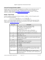
Checksums are calculated over the bytes following the length field, up to but not including the
checksum field using the following table and pseudo code:
const int8 crc8_Table[
{
0, 94, 188, 226,
157, 195, 33, 127,
35, 125, 159, 193,
190, 224,
2, 92,
70, 24, 250, 164,
219, 133, 103, 57,
101, 59, 217, 135,
248, 166, 68, 26,
140, 210, 48, 110,
17, 79, 173, 243,
175, 241, 19, 77,
50, 108, 142, 208,
202, 148, 118, 40,
87,
9, 235, 181,
233, 183, 85, 11,
116, 42, 200, 150,
};
] =
97,
252,
66,
223,
39,
186,
4,
153,
237,
112,
206,
83,
171,
54,
136,
21,
63,
162,
28,
129,
121,
228,
90,
199,
179,
46,
144,
13,
245,
104,
214,
75,
221,
64,
254,
99,
155,
6,
184,
37,
81,
204,
114,
239,
23,
138,
52,
169,
131,
30,
160,
61,
197,
88,
230,
123,
15,
146,
44,
177,
73,
212,
106,
247,
194,
95,
225,
124,
132,
25,
167,
58,
78,
211,
109,
240,
8,
149,
43,
182,
156,
1,
191,
34,
218,
71,
249,
100,
16,
141,
51,
174,
86,
203,
117,
232,
126,
227,
93,
192,
56,
165,
27,
134,
242,
111,
209,
76,
180,
41,
151,
10,
32,
189,
3,
158,
102,
251,
69,
216,
172,
49,
143,
18,
234,
119,
201,
84,
163,
62,
128,
29,
229,
120,
198,
91,
47,
178,
12,
145,
105,
244,
74,
215,
253,
96,
222,
67,
187,
38,
152,
5,
113,
236,
82,
207,
55,
170,
20,
137,
31,
130,
60,
161,
89,
196,
122,
231,
147,
14,
176,
45,
213,
72,
246,
107,
65,
220,
98,
255,
7,
154,
36,
185,
205,
80,
238,
115,
139,
22,
168,
53
Table 3: Checksum value lookup table.
To use the table:
crc = 0x01;
for ( each byte_Value between length and
checksum fields)
{
crc = crc8_Table[ crc ^ byte_Value ] ;
}
Table 4: Psudo code describing how to generate CRC checksum.
Copyright © 2014-2015 SightLine Applications, Inc.
Page 10 of 95
Jan 15, 2015
SightLine Applications Command and Control
Checksum Calculation Example:
Data
Description Action
CRC
0x51
Header 1
Ignored
0x01
0xAC
Header 2
Ignored
0x01
0x02
Length
Ignored
0x01
0x07
Type
Used
Look up result
0x01 ^ 0x07 = 0x06
Table[6] = 221 (0xDD)
Table 5: Example Checksum Calculation
CRC should equal 221.
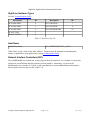
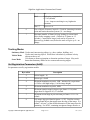
Serial Port
Serial port parameters are configured:
Baud
Data Bits
Stop Bits
Parity
Handshake
57600
8
1
None
None
Table 6: Default Serial Port Configuration
See Serial Port Parameters for additional baud rates supported.
•
You can set the serial port properties of the unit explicitly using the Configure Communication
Port (0x3E) command.
•
Refer the specific hardware ICD to determine if serial port is 3.3VTTL or RS-232C level
signals.
Ethernet
Command and control is also available over Ethernet.
All commands can be sent as a UDP packet to the IP Address of the system on port 14001. All replies
will be sent to the IP address of the sender on port 14002. The ports can be changed using Set Network
Parameters (0x1C).
Copyright © 2014-2015 SightLine Applications, Inc.
Page 11 of 95
Jan 15, 2015
SightLine Applications Command and Control
Transport Layer
Inbound Port
Reply Port
UDP
14001
14002
Table 7: Ethernet Ports Used
IP Address Assignment
•
You can set a STATIC IP address of the SLA-HARDWARE explicitly using Set Network
Parameters (0x1C).
•
If no STATIC IP address has been set, the SLA-HARDWARE will attempt to obtain an IP
address using DHCP.
•
If DHCP fails, the SLA-2000 will use a 192.168.1.ddd, where ddd is internally determined
using its MAC address.
•
SLA-1500 (etc.): If DHCP fails, the system will use a specific Link Local (RFC 3927)
type address 169.254.1.180.
Summary Table
If Static...
IP Address User Defined
Subnet Mask User Defined
Gateway
User Defined
Else try DHCP...
DHCP Defined
DHCP Defined
DHCP Defined
If DHCP Fails try...
SLA-2000
All Other
192.168.1.ddd 169.254.1.180
255.255.255.0 255.255.0.0
192.168.1.1 NOT DEFINED
Table 8: IP Address Assignment
TIP: Use this table as guidance for setting the IP address of your PC.
Discover Protocol
When the SightLine Hardware powers up it will broadcast an SLDISCOVER packet identifying itself.
The system also listens for SLDISCOVER Requests.
Transport Layer
IP Address
Port
UDP
255.255.255.255
51000
Table 9: Discover Protocol Packet
Copyright © 2014-2015 SightLine Applications, Inc.
Page 12 of 95
Jan 15, 2015
SightLine Applications Command and Control
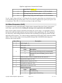
Discover Packet Payload
3
2
1
0
ID
4
Length
0
8
Major Version
Minor Version
12
Software Features
Hardware Type
16
MAC ADDRESS
...
36
IP ADDRESS
(see Set Network Parameters (0x1C))
...
52
Video Address
(See Set Ethernet Video Parameters (0x1A))
...
68
HOST NAME
(see Set Host Name (0x66))
...
100
Video Port
(see Video Address)
C2 Port
Table 10: Discover Protocol Packet Layout
Byte
Length
Name
Description
0
4
ID
Magic identifier number
4
4
Length
Discover message length
8
2
Minor Version
Discover protocol minor version.
10
2
Major Version
Discover protocol major version.
12
2
Software Features
Services provided (internal use only)
14
2
Hardware Type
See below
16
20
MAC
MAC address of sender
36
16
IP Address
IP address of sender
52
16
Video Address
IP Address where images are sent (multicast or unicast)
68
32
Host Name
Human Readable name of hardware
100
2
Video Port
Port number where images are sent
102
2
C2 Port
Port number open to receive commands (default 14001)
Table 11: Discover Protocol Packet Description
Copyright © 2014-2015 SightLine Applications, Inc.
Page 13 of 95
Jan 15, 2015
SightLine Applications Command and Control
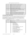
SightLine Hardware Types
See also Version Number (0x40).
Description
ID
Description
ID
SLA-2000-OEM
0
SLA-1500-OEM
7
SLA-2100-OEM
1
SLA-1501-OEM
8
SLA-1000-OEM
4
SLA-UPGRADE-SRV
10
SLA-PC-WIN
5
SLA-PC-LINUX
6
Table 12: Hardware Type ID
Host Name
Default Host Name
SLA<HARDWARE TYPE>_<MAC>
Where MAC is last 3 octets of the MAC address. This host name be changed to something more
unique or applicable to your application by using Set Host Name (0x66).
Network Interface Controllers (NIC):
SLA-HARDWARE may contain one or more physical network interfaces. For example, a system may
include one wired Ethernet interface and one wireless interface. Alternately, a system can be
Multihomed, have a number of VLANs, or other mechanisms to create additional network interfaces.
Most systems will have only one NIC (index = 0).
Copyright © 2014-2015 SightLine Applications, Inc.
Page 14 of 95
Jan 15, 2015
SightLine Applications Command and Control
Commands
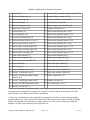
Common Commands
For reference purposes, below are a list of the the most frequently used commands.
Basic Stabilization and Tracking:
Set Registration Parameters (0x0E)
Set Stabilization Parameters (0x02)
Set Tracking Parameters (0x0C)
Set Coordinate Reporting Mode (0x0B)
Modify Tracking (0x05)
Moving Target Detection:
Set Stabilization Parameters (0x02)
Make sure you set Mode = 1 in addition to the
other parameters
Set Overlay Mode (0x06)
Enable Overlays so you can see the detection
boxes
Set Coordinate Reporting Mode (0x0B)
Enable reporting so the SLA-2000 sends back
telemetry Flags = 7
Set Moving Target Indication Parameters (0x2D) Set the Mode = 2 and change the Threshold = 5
(default). You can adjust the threshold down (1 =
most sensitive and more false positives).
Then look for the following replies:
Current Tracking Positions (0x51)
See Set Network Parameters (0x1C) and Set Packet Destination (0x64) to define where responses and
telemetry will be sent. Querying the state of the hardware is now done using the generalized Get
Parameters Function (0x28) which takes the “setter” type ID as an input. In a few cases, some more
complicated messages have been implemented to get other types of results or status.version
Copyright © 2014-2015 SightLine Applications, Inc.
Page 15 of 95
Jan 15, 2015
SightLine Applications Command and Control
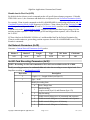
Get Version (0x00)
Get Parameters Function (0x28)
Version (0x00)
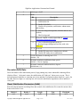
Reset (0x01)
Allow user to reset different aspects of the system.
Byte offset
Description
2
Packet length = 3
3
Packet type = 0x01
Reset Type:
Value
4
Description
0
parameters only reset to factory defaults
1
video decoder
2
board soft reset (reboot board with saved defaults)
3
Stop application (SLA-1500-ONLY)
4
Deletes any saved parameter files and soft resets the
board NEW 2.17
5
Send reset command to any known camera attached
(TAU, Sony, etc) NEW 2.18
6
Soft parameter only reset to factory defaults (does not
reset network, serial port or camera type settings)
NEW 2.18
7 – 255
Reserved
Set Stabilization Parameters (0x02)
Turn on or turn off stabilization and control re-centering rate for output video. Video stabilization
smooths out jumpy sequences caused by camera vibration. Default value is “on” with re-centering rate
= 50. A low number (approaching 0) = a slow drift to center. A high number (approaching 255) = a fast
drift to center (see note below). Maximum stabilization limit is used to set an upper bound on the timeaveraged stabilization solution.
NOTE: Bit 3 of the Mode field in the Current Stabilization Parameters (0x41) packet indicates the state
of the Auto-Bias algorithm. See Set Stabilization Bias (0x12) for more information on enabling AutoBias.
Byte Offset
2
Copyright © 2014-2015 SightLine Applications, Inc.
Description
Packet length = 6
Page 16 of 95
Jan 15, 2015
SightLine Applications Command and Control
3
Packet type = 0x02
4
Mode:
Bit
Description
0
0 – Stabilization OFF (default)
1 – Stabilization ON
1
0 – Enable all (default)
1 – Disable all registration, stabilization, enhancement,
and tracking
2
0 – Previous Images background, with blur and no color
(default)
1 – Black background
3
Reserved - NOTE: Used for Auto-Bias in Current
Stabilization Parameters (0x41).
4
0 – Grey or black background (see bit 2)
1 - Previous Images background, no blur, with color
NEW 2.17
5–6
7
Reserved
0 – Enable PIP image micro stabilization (default)
1 – Disable PIP image micro stabilization
5
Screen translation re-centering rate 0..255
(default = 50)
6
Maximum translation stabilization limit, pixels
(default = 0 for no clipping)
7
Maximum rotational stabilization limit, degrees
(default none = 0)
Re-center (Drift) Rate:
Due to the nature of the stabilization process, large panning may cause undesirable rendering effects
(display offsets). In layman's terms, the stabilization will “fight you” when you try to pan. This is
most pronounced when the re-centering rate is low and there is sustained camera motion (i.e. pan). On
the other hand, too high a re-centering rate will cause the stabilization algorithm to allow undesired
video jitter.
Reset Stabilization Parameters (0x04)
Reset the internal motion smoothing filters that control video stabilization. Re-center the current video
frame in the field of view.
Header 1
Header 2
Length
Type
Checksum
0x51
0xAC
0x02
0x04
0x3F
Copyright © 2014-2015 SightLine Applications, Inc.
Page 17 of 95
Jan 15, 2015
SightLine Applications Command and Control
Set Overlay Mode (0x06)
Byte offset
Description
2
Packet length = 5
3
Packet type = 0x06
4
Bits 0..3 Primary 0 = off
track color mode 1 = white (default)
2 = black
3 = auto (white or black)
4 = rainbow
5 = red
6 = orange
7 = yellow
8 = green
9 = blue
10 = violet
Bits 4..7 Primary 0 = box corners (default)
track reticle type 1 = cross
2 = circle
3 = duplex crosshair
4 = modern range
5 = target dot
6..15 = Reserved
5
6
Copyright © 2014-2015 SightLine Applications, Inc.
Bits 0..3
Secondary track color mode (SLA-2000 only)
Same as primary track color mode, above
Bits 4..7
Secondary track reticle type (SLA-2000 only)
Same as primary track reticle type, above
Bits 0..2
Reserved = 0
Bit 3
Overlay Histogram
0 = don't
1 = do
Bit 4
Overlay track index
0 = don't
1 = do
Bit 5
Show track motion trails
0 = don't
1 = do
Bit 6
Reserved = 0
Bit 7
Show registration ignore edge lines
Page 18 of 95
Jan 15, 2015
SightLine Applications Command and Control
0 = don't
1 = do
Start Tracking (0x08) (Deprecated)
See Modify Tracking (0x05)
Command the system to start a track. Column and Row coordinates correspond to the pixel coordinate
within a 640x480 frame of video in display (stabilized) coordinates. The origin is in the upper left
corner of the image with values increasing down and to the right. Up to 5 tracks may be
simultaneously engaged.
Byte offset
Description
2
Packet length = 7
3
Packet type = 0x08
4
0..639: Column coordinate, LSB
5
Column coordinate, MSB
6
0..479: Row coordinate, LSB
7
Row coordinate, MSB
8
Track Modifier
Bit 0:
0: cursor only
1: initiate tracking
Bit 1:
0 – Default
1 – Rotate and zoom coordinates with
display
Bit 2:
0 – Default
1 – Replace all tracks with one track at
designated coordinates (SLA-2000 only)
Bit 3:
0 – Default
1 – Add New (SLA-2000 only)
Bit 4:
0 – Default
1 – Replace Near (SLA-2000 only)
Bit 5:
0 – Default
1 – Designate Moving Target Near as
Primary (SLA-2000 only)
Bit 6
0 – Default
1 – Kill Near (SLA-2000 only)
Modify Tracking (0x05)
Command the system to modify tracking: start a track, stop a track, designate a track as primary, nudge
Copyright © 2014-2015 SightLine Applications, Inc.
Page 19 of 95
Jan 15, 2015
SightLine Applications Command and Control
a track, etc. Column and Row coordinates correspond to the pixel coordinate within a 640x480* frame
of video in display (stabilized) coordinates. The origin is in the upper left corner of the image with
values increasing down and to the right. Up to 5 tracks may be simultaneously engaged. See the
Target Tracking Guide for more details about multiple target tracking.
* see Current Image Size (0x4E) for more information about capture image size
Byte offset
Description
2
Packet length = 7
3
Packet type = 0x05
4
Column coordinate, LSB
5
Column coordinate, MSB
6
Row coordinate, LSB
7
Row coordinate, MSB
8
Flags
Copyright © 2014-2015 SightLine Applications, Inc.
0x80
Rotate Zoom Modifier. OR this flag (set high
bit to 1) with any any of the flags below to
indicate coordinates are rotated and zoomed
with the display.
0x40
Source Coordinates. OR this flag (set bit 6 to 1)
with any other of the flags below to indicate that
the coordinates specified are in the source
image. By default, don't set this flag (bit 6 = 0)
for coordinates in the display image space.
0x00
Show Cursor only
0x01
Kill any existing targets and then designate a
new primary target at the cursor.
0x02
Designate another target at the cursor.
0x03
If there is a track near the coordinates, move
track to coordinates.
0x04
If there is a track near the coordinates, move
track to coordinates. Otherwise, add a new
track at coordinate location.
0x05
Designate track near coordinates as primary
target.
0x06
Designate track near coordinates as primary
target if there is one. If not, add new track at
coordinates.
0x07
If there is a track near coordinates, move track
Page 20 of 95
Jan 15, 2015
SightLine Applications Command and Control
to location of coordinates and designate as
primary. Otherwise, add a new track at
coordinates and make primary.
0x08
If there is a track near coordinates, move track
to location of coordinates and designate as
primary. Otherwise, kill all existing tracks and
add a new primary track at location of
coordinates.
0x09
Kill track near coordinates.
0x0A
Kill all tracks, but the primary track.
(Coordinates are ignored).
Modify Track By Index (0x17)
Modify a particular track by its index (stop or designate as primary)
Byte offset
Description
2
Packet length = 4
3
Packet type = 0x17
4
Track Index
5
0 = Stop Track
1 = Make Primary
Stop Tracking (0x09)
Turn off all tracks.
Byte offset
Value
Description
2
0x05
Packet length
3
0x09
Packet type
4
0x00
Reserved
5
0x00
Reserved
6
0x00
Reserved
7
0x1C
Checksum
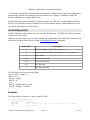
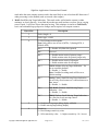
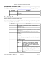
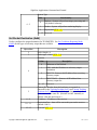
Nudge Tracking Coordinates (0x0A)
Adjust the primary track's coordinates by adding a nudge in pixel coordinate space to the current
tracking coordinates.
Byte offset
Copyright © 2014-2015 SightLine Applications, Inc.
Description
Page 21 of 95
Jan 15, 2015
SightLine Applications Command and Control
2
Packet length = 5
3
Packet type = 0x0A
4
-128..127: Column adjustment
(2's complement signed 8-bit integer)
5
-128..127: Row adjustment
(2's complement signed 8-bit integer)
6
Nudge Mode:
0: Do not rotate command with display
1: Rotate command with display
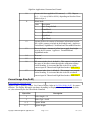
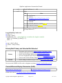
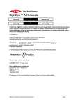
Nudge Mode
Applies the display rotation set using Set Display Parameters (0x16) to the nudge command.
Assume rotation enable to 45°.
Original Image
“Do not rotate command with display”
“Rotate command with display”
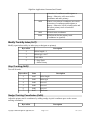
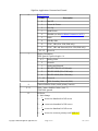
Set Coordinate Reporting Mode (0x0B)
Set the reporting rate of Tracking Position (0x43) and Current Tracking Positions (0x51) packets. The
Tracking Position (0x43) packet contains measured previous frame to current frame offset, angle and
scale, display offset/rotation, and primary track position. The Current Tracking Positions (0x51) packet
contains the positions of all targets currently being tracked. All packets will be from the primary
camera as selected by Set Video Parameters (0x10). Default reporting rate is “no coordinate reporting”.
Byte offset
Description
2
Packet length = 5
3
Packet type = 0x0B
4
Frame period mode:
0 = no coordinate reporting (default)
1 = report coordinates every frame (29.97 Hz)
2 = report coordinates every 2nd frame
3 = report coordinates every 3rd frame
...
Copyright © 2014-2015 SightLine Applications, Inc.
Page 22 of 95
Jan 15, 2015
SightLine Applications Command and Control
Flags: Types of Output
Bit
5
6
Description
0x00
(DEFAULT)
Send Tracking Position and Tracking Positions of
primary track only. Same as 0x03
0x01
Send Tracking Position - sends Tracking Position
(0x43)
0x02
Send Tracking Positions of primary track – sends
Current Tracking Positions (0x51)
0x04
Send Tracking Positions of non-primary tracks –
sends Current Tracking Positions (0x51)
0x20
Prioritize Stab/Track/Telemetry over
Render/Enhance/Compress/Display. If this bit is
on and telemetry is reported every frame, the
system may skip displaying some frames so that it
can maintain 30Hz telemetry output rate. NEW
2.17
0x40
Report Tracking Box Pixel Stats (0x78) over
Track Box Area NEW 2.20
Unused Bits
Reserved
Reserved = 0
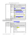
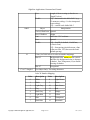
Set Tracking Parameters (0x0C)
Set parameters used by tracking module. See also Tracking Position (0x43).
Byte offset
Description
2
Packet length = 6
3
Packet type = 0x0C
4
Size of object, in pixels, to track. (for user designated tracking)
5
Mode (see below for description).
Bits 0..3
0 = no change FIX 2.17.8
1 = Stationary mode
2 = Vehicle mode
3 = Reserved
4 = Scene mode
5..15 = Reserved
Note that if tracking mode is set to stationary, then
all moving target detection will be turned off if it is
Copyright © 2014-2015 SightLine Applications, Inc.
Page 23 of 95
Jan 15, 2015
SightLine Applications Command and Control
on.
Bit 4
High noise compensation
0 = off (default)
1 = on – improves tracking in very high noise
situations
Bits 5..7
Reserved = 0
6
Size of object of interest, in pixels. (Used for clustering in motion
assist and motion detection systems.) 0 = no change.
7
Maximum number of frames to keep looking for a non-found
object before stopping a track. (Default is 45 frames or 1.5
seconds.) Controls how long a track can be off screen or
obscured (eg. behind a tree) before the track will give up. 0 = no
change
Tracking Modes
Stationary Mode Used to track non-moving object (e.g. door, window, building, etc.).
Used to track moving objects. Works best with relatively constant velocity
Vehicle Mode
objects such as a car.
Uses frame-to-frame registration to determine position of target. May work
Scene Mode
better than Stationary Mode for low-contrast non moving targets.
Set Registration Parameters (0x0E)
Set parameters used by registration module.
Byte offset
Description
2
Packet length = 10
3
Packet type = 0x0E
4
Maximum translation in pixels, LSB – default of 0 is equivalent
to 120 for a 480 high image (¼ of the image height)
5
Maximum translation in pixels, MSB
6
Maximum rotation range in degrees per frame: 0..10 (values
larger than 10 clipped to 10). 5 is default.
7
Maximum zoom range in percent zoom per frame: 0..10. 0 is
default.
8
Left image edge pixel band to ignore. 0..255. Used for overlays
or foreground objects that appear near the edge of the image. 0 is
default. At least ¼ of the smaller dimension of the image must be
remaining. For NTSC, remaining non-ignored image must be at
Copyright © 2014-2015 SightLine Applications, Inc.
Page 24 of 95
Jan 15, 2015
SightLine Applications Command and Control
least 120x120. MOD 2.17
9
Right image edge pixel band to ignore. 0..255 0 is default.
10
Top image edge pixel band to ignore. 0..255 0 is default.
11
Bottom image edge pixel band to ignore. 0..255 0 is default.
Use the “ignore edge pixel band” to indicate that the registration algorithm to not include these pixels
when determining the registration match. This can be used to compensate for effects of the optics such
as vignetting or when there is an obstruction along an edge of the image.
Set Video Parameters (0x10)
Set parameters used by tracking module. Default values: automatic detection of active video region
(auto-chop), apply deinterlacing. Sending this message resets registration and stabilization.
Many cameras produce images with black pixels along one or more edges. It is important to remove
these pixels as the hard edge transition can cause frame-to-frame registration to fail. The edge pixels
are removed by either setting automatic detection mode or manually specifying top, bottom, left and
right edge pixels to remove. For a known camera, manually specifying edge pixels is the most reliable
option. If you see black edges in a moving stabilized image, that is an indication that edge pixel
removal is not set up correctly.
Byte offset
Description
2
Packet length = 9
3
Packet type = 0x10
Auto-chop
Value
4
Description
0
removed specified edge pixels (recommended)
1
automatically detect boundary pixels to remove
(default)
Pixels to remove (Value is rounded down to the nearest 8. )
5
Top pixels to remove (0..255)
6
Bottom pixels to remove (0..255)
7
Left pixels to remove (0..255)
8
Right pixels to remove (0..255)
Deinterlacing mode:
9
Value
Copyright © 2014-2015 SightLine Applications, Inc.
Description
0
no deinterlacing
1
apply digital deinterlacing
Page 25 of 95
Jan 15, 2015
SightLine Applications Command and Control
Automatically reset video decoder when failed frame synchronization
loss is detected
Value
10
Description
0
Never
1
When frame synchronization loss detected
Set Stabilization Bias (0x12)
Adjust the stabilization solution by adding a constant bias in pixel coordinate space to the current
coordinates each frame. This is used to feed forward user controlled camera motion so that
stabilization does not “fight” against camera pan and tilt. Set “auto bias” mode to automatically
prevent the system from stabilizing against constant motion. Some amount of motion lag will still be
experienced in “auto bias” mode.
NEW 2.18 Manual bias offsets can be used in “auto bias” mode. In “auto bias” mode, set column and
row bias to 0 for “auto bias” only. Changes to the column and row bias values will be added to the
“auto bias” solution.
Byte offset
Description
2
Packet length = 5
3
Packet type = 0x12
4
-128..127: Per frame column adjustment (bias) in pixels
(signed 8-bit integer)
5
-128..127: Per frame row adjustment (bias) in pixels
(signed 8-bit integer)
6
1 = Enable auto bias (combined auto + manual bias)
0 = Disable auto bias (manual bias only)
Set Metadata Data Values (0x13)
Sets new KLV metadata data values. Latest values are output with h.264 digital video stream.
Metadata is generated in accordance with MISB standards 0102.10, 0601.7, 0603.2, 0604.3, and
0903.3. Selectable KLV elements may be chosen from a superset of the Motion Imagery Sensor
Minimum Metadata Set defined in ST 0902.3. For conversion of values see Table 1 on page 16 of:
http://www.gwg.nga.mil/misb/docs/standards/ST060107.pdf.
Byte offset
Description
2
Packet length = 44
3
Packet type = 0x13
4–5
Valid data bit mask. Update corresponding data element when bit
value = 1. Unsigned 16 bit integer
6 – 13
UTC time (bit 0) unsigned 64-bit integer
Copyright © 2014-2015 SightLine Applications, Inc.
Page 26 of 95
Jan 15, 2015
SightLine Applications Command and Control
14 – 15
Platform heading angle (bit 1) unsigned 16-bit integer
16 – 17
Platform pitch angle (bit 2) signed 16-bit integer
18 – 19
Platform roll angle (bit 3) signed 16-bit integer
20 – 21
Sensor latitude (bit 4) signed 32-bit integer
24 – 27
Sensor longitude (bit 5) signed 32-bit integer
28 – 29
Sensor altitude (bit 6) unsigned 16-bit integer
30 – 31
Sensor horizontal field of view (bit 7) unsigned 16-bit integer
32 – 32
Sensor vertical field of view (bit 8)
unsigned 16-bit integer
34 – 37
Sensor relative azimuth angle (bit 9) unsigned 32-bit integer
38 – 41
Sensor relative elevation angle (bit 10) signed 32-bit integer
42 – 45
Sensor relative roll angle (bit 11) unsigned 32-bit integer
Set Metadata Static Values (0x14)
Sets new KLV metadata values. Latest values are output with H.264 digital video stream, at the rate for
each element specified by message 0x62. For non-string values, data encoding is big-endian as
defined by MISB 0603. For example, to encode Target Error Estimate CE90 which is specified as a
uint16 value, “Identifier string length” should be set to 2, byte 6 to the most significant byte of the
value, and byte 7 to the least significant byte of value.
Byte offset
Description
2
Packet length = 4+n
3
Packet type = 0x14
4
Static element identifier:
0 = Mission Identifier
1 = Platform Designation
2 = Image Source Sensor
3 = Image Coordinate System
4 = Security: Classification
5 = Security: Classifying country coding method
6 = Security: Classifying country
7 = Security: SCI/SHI information
8 = Security: Caveats
9 = Security: Releasing Instructions
10 = Security: Object Country Coding Method
11 = Security: Object Country
12 = Motion Imagery Core Identifier
13 = Platform Tail Number
14 = Target Error Estimate CE90
Copyright © 2014-2015 SightLine Applications, Inc.
Page 27 of 95
Jan 15, 2015
SightLine Applications Command and Control
15 = Target Error Estimate LE90
16 = Generic Flag Data 01
17 = Platform Call Sign
5
6 – (6+n-1)
Identifier string length (n)
Identifier string
Set Metadata Frame Data Values (0x15)
Sets new KLV metadata frame data values. Latest values are output with H.264 digital video stream.
Byte offset
Description
2
Packet length = 20
3
Packet type = 0x15
4–5
Valid data bit mask. Update corresponding data element when bit
value = 1. Unsigned 16 bit integer
6–9
Frame center latitude (bit 0) signed 32-bit integer
10 – 13
Frame center longitude (bit 1) signed 32-bit integer
14 – 15
Frame center elevation (bit 2) unsigned 16-bit integer
16 – 17
Target width (bit 3) unsigned 16-bit integer
18 – 21
Slant range (bit 4) unsigned 32-bit integer
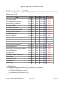
Set Metadata Rate (0x62)
Sets the frame step rates at which KLV metadata is output.
Byte offset
Description
2
Packet length = 11
3
Packet type = 0x62
4 – 11
Set rate bit mask. Update the rate for the corresponding data
element when bit value = 1. The table below describes these bits.
Unsigned 64 bit integer
12
Frame step at which to send the specified data values. 0=disable
sending KLV metadata, 1=send each frame, etc.
Bit field number
Bit
Field
0 UTC time (2)
Copyright © 2014-2015 SightLine Applications, Inc.
Bit
Field
26 Security: Releasing instructions (48/6)
Page 28 of 95
Jan 15, 2015
SightLine Applications Command and Control
1 Mission ID (3)
27 Security: Object country coding method (48/12)
2 Platform heading angle (5)
28 Security: Object country (48/13)
3 Platform pitch angle (6)
29 Security: Metadata version (48/22)
4 Platform roll angle (7)
30 UAS local set version (65)
5 Platform designation (10)
31 Motion imagery core identifier (94)
6 Image source sensor (11)
32 Platform tail number (4)
7 Sensor latitude (13)
33 Offset corner latitude point 1 (26)*
8 Sensor longitude (14)
34 Offset corner longitude point 1 (27)*
9 Sensor true altitude MSL (15)
35 Offset corner latitude point 2 (28)*
10 Sensor horizontal field of view (16)
36 Offset corner longitude point 2 (29)*
11 Sensor vertical field of view (17)
37 Offset corner latitude point 3 (30)*
12 Sensor relative azimuth angle (18)
38 Offset corner longitude point 3 (31)*
13 Sensor relative elevation angle (19)
39 Offset corner latitude point 4 (32)*
14 Sensor relative roll angle (20)
40 Offset corner longitude point 4 (33)*
15 Frame center latitude (23)
41 Target location latitude (40)**
16 Frame center longitude (24)
42 Target location longitude (41)**
17 Frame center elevation MSL (25)
43 Target location elevation (42)**
18 Target width (22)
44 Target track gate width (43)**
19 Slant range (21)
45 Target track gate height (44)**
20 Image coordinate system (12)
46 Target error estimate CE90 (45)
21 Security: Classification (48/1)
47 Target error estimate LE90 (46)
22 Security: Classifying country coding
method (48/2)
48 Generic flag data 01 (47)
23 Security: Classifying country (48/3)
49 Platform call sign (59)
24 Security: SCI/SHI information (48/4)
50 Vmti LDS targets (74)***
25 Security: Caveats (48/5)
*Values are calculated from platform angles, sensor angles, sensor position, frame center position, and
slant range that are supplied by messages 0x13 and 0x15. All four corners are assumed to be at the
same elevation as the frame center for these calculations.
**Values are calculated from values supplied by messages 0x13 and 0x15, and by internal tracking
position and box size. Target elevation is assumed to be the same as frame center elevation, and target
latitude and longitude are calculated in a manner similar to the four corners. Track gate width and
height are in pixels, derived directly from target box size.
Copyright © 2014-2015 SightLine Applications, Inc.
Page 29 of 95
Jan 15, 2015
SightLine Applications Command and Control
***Values are calculated from internal tracking information. Multiple targets (either user-designated or
automatically-generated) are indicated. Pixel coordinates are in “display” coordinates suitable for
directly rendering over streamed digital video.
Sets the frame step rates at which KLV metadata is output. Per STD 0601, version identifier fields for
the UAS Local Data Set, Security Metadata Local Set, and Motion Imagery Track Metadata Local Set
are emitted with elements of each local set.
Set KLV Data (0x61)
Set KLV blob data constructed by user to be sent with H.264 stream. The KLV data will be sent along
with the next H.264 frame.
When you use this feature, you may want to disable the transmission of the built-in KLV metadata. You
can do that by setting Frame step to 0 using Set Metadata Rate (0x62) command.
Byte offset
Description
2
KLV data length + 4 (if > 127, see below)
3
Optional high bits of KLV data length (if > 127, see below)
n
Type = 0x61
n+1
Reserved (must be 0)
n+2
Reserved (must be 0)
n+3
KLV data start
...
KLV data continued
The following is used to set the data length:
u16 len = KLV_Length + 4;
if(len<=127) {
data[2] = length;
data[3] = 0;
} else {
data[2] = (length & 0x7f) | 0x80;
data[3] = (length>>7) & 0xFF;
}
Example:
The following byte sequence is a packet with KLV data.
const unsigned char setKlvDataPacket[] = {
//TotalPacketLen=163, klvLen=155
0x51, 0xac,
// Signature bytes
0x9f, 0x01,
// Length (159 (0x9f) bytes: type(1) + reserved(2) + KLV(155) + checksum(1))
0x45,
// Type (SetKlvData)
Copyright © 2014-2015 SightLine Applications, Inc.
Page 30 of 95
Jan 15, 2015
SightLine Applications Command and Control
0x00, 0x00,
// KLV Data
0x06, 0x0e,
0x81, 0x89,
0x6d, 0x70,
0x20, 0x53,
0x63, 0x61,
0x02, 0x00,
0x02, 0x00,
0x00, 0x13,
0x00, 0x00,
0x00, 0x15,
0x7a
// Reserved
(155 bytes)
0x2b, 0x34, 0x02,
0x02, 0x08, 0x00,
0x6c, 0x65, 0x20,
0x69, 0x67, 0x68,
0x74, 0x69, 0x6f,
0x00, 0x0d, 0x04,
0x00, 0x10, 0x02,
0x04, 0x00, 0x00,
0x00, 0x18, 0x04,
0x04, 0x00, 0x00,
// Checksum
(must be 0)
0x0b,
0x04,
0x4b,
0x74,
0x6e,
0x00,
0x00,
0x00,
0x00,
0x00,
0x01,
0xb2,
0x4c,
0x4c,
0x73,
0x00,
0x00,
0x00,
0x00,
0x00,
0x01,
0xf0,
0x56,
0x69,
0x05,
0x00,
0x11,
0x14,
0x00,
0x01,
0x0e,
0xcc,
0x20,
0x6e,
0x02,
0x00,
0x02,
0x04,
0x00,
0x02,
0x01,
0x84,
0x64,
0x65,
0x00,
0x0e,
0x00,
0x00,
0x19,
0xab,
0x03,
0xe8,
0x61,
0x20,
0x00,
0x04,
0x00,
0x00,
0x02,
0x22,
0x01,
0x00,
0x74,
0x41,
0x06,
0x00,
0x12,
0x00,
0x00,
0x01,
0x03,
0x61,
0x70,
0x02,
0x00,
0x04,
0x00,
0x00,
0x00,
0x29,
0x20,
0x70,
0x00,
0x00,
0x00,
0x17,
0x16,
0x00,
0x53,
0x62,
0x6c,
0x00,
0x00,
0x00,
0x04,
0x02,
0x00,
0x61,
0x79,
0x69,
0x07,
0x0f,
0x00,
0x00,
0x00,
};
Set Display Parameters (0x16)
Sets new display parameter settings. Current rotation is smoothly changed to specified value, digital
zoom, and false color modes may be controlled.
Byte offset
Description
2
Packet length = 14
3
Packet type = 0x16
4–5
Rotation angle in degrees
(0..360) * 128
6–7
Rotation rate limit in degrees
(0..360) * 128 per frame (29.97 Hz)
8
Decay rate 0 to 255
9
Bits 0 - 6: False color mode:
0, 1 = no false color
2, 3 = white hot, black hot
4, 5 = rainbow, rainbow inverted
6, 7 = iron, iron inverted
8, 9 = hot/cold, hot/cold inverted
10, 11 = jet, jet inverted
12, 13 = hot, hot inverted
14, 15 = HSV, HSV inverted
16, 17 = 470CLR_S, 470CLR_S inverted
18, 19 = Color1, Color1 inverted
20, 21 = Color2, Color2 inverted
22, 23 = Color3, Color3 inverted
24, 25 = hot iron, hot iron inverted
26, 27 = ice fire, ice fire inverted
28, 29 = IDDEF, IDDEF inverted
30, 31 = Iron256, Iron256 inverted
32, 33 = Rain256, Rain256 inverted
34, 35 = XVolcano, XVolcano inverted
36, 37 = Red, Red inverted
38, 39 = Green, Green inverted
Copyright © 2014-2015 SightLine Applications, Inc.
Page 31 of 95
Jan 15, 2015
SightLine Applications Command and Control
40, 41 = Blue, Blue inverted
127 = User Palette. See Set User Palette (0x72) command.
Bit 7: Zoom mode
0 = zoom to center of display
1 = zoom to tracking box
10
Zoom – digital image magnification factor times 64.
0 to 31 – No zoom (1X) (subject to change)
32 to 63 – Zoom out by 0.5 to 0.98
64 – No zoom (1X)
65-255 – Zoom in by 1.01 to 3.98
NOTE: Zoom factors may be further limited for some HD
camera and hardware combinations.
11, 12
Display pan column offset in pixels (-32767 to 32768).
13, 14
Display tilt row offset in pixels (-32767 to 32768).
15
Logical Camera Index
Specifies the logical camera to apply the false color field to (byte
9). See Set Video Mode (0x1F) (bytes 8-11) for information about
setting logical camera order.
Note: 0 is assumed if parameter is not supplied.
Get Display Parameters (0x3A)
Query the system for the current display parameters. Results in the transfer of a Current Display
Parameters (0x57) packet.
Byte offset
Description
2
Packet length = 3
3
Packet Type = 0x3A
4
Logical Camera Index. Specifies the logical camera's index to
retrieve enhancement parameters of.
Note: 0 is assumed if parameter is not supplied.
Set ADC Parameters (0x18)
Set parameters of the video analog-to-digital converter. See also Current ADC Parameters (0x47).
Not functional on Digital Camera Inputs.
Byte offset
Description
2
Packet length = 12
3
Packet type = 0x18
4
Brightness
0 = dark
Copyright © 2014-2015 SightLine Applications, Inc.
Page 32 of 95
Jan 15, 2015
SightLine Applications Command and Control
128 = default
255 = bright
5
Contrast
0 = minimum contrast
128 = default
255 = maximum
6
Saturation
0 = no color
128 = default
255 = maximum
7
Hue
8-bit signed integer (-128..127)
0 = default
8
Luma processing control #1 register (0x07)
96 (0x60) = default
9
Luma processing control #2 register (0x08)
0 = default
10
Luma processing control #3 register (0x0E)
0 = default
11
Chroma processing control #1 register (0x1A)
12 (0x0C) = default
12
Chroma processing control #2 register (0x1B)
20 (0x14) = default
13
Reserved NEW 2.18
Set Ethernet Video Parameters (0x1A)
Effects the quality (RTP-MJPEG only), size and frame rate of the individual video frames sent over
Ethernet. See Set H.264 Video Parameters (0x23) for additional H.264 specific parameters.
Byte offset
Description
2
Packet length = 6 (or 8 for 3000)
3
Type = 0x1A
4
Quality – MJPEG video only. 0: lowest image quality to 100:
highest image quality
0 to 100 (default 80)
5
Foveal – MJPEG video only. Reduces image quality for pixels
away from image center. 0: no quality reduction, 100: maximum
quality reduction.
Copyright © 2014-2015 SightLine Applications, Inc.
Page 33 of 95
Jan 15, 2015
SightLine Applications Command and Control
0 to 100 (default 0)
6
Frame Step - 1 shows every frame, 2 shows every other frame,
etc. Applies to both MJPEG and H.264 Ethernet video.
1 to 120 (default 1)
7
Lower nibble: Down Sample – Whole integer value that image
will be down sampled by. Applies to both MJPEG and H.264
Ethernet video.
0, 1 = no downsample
2 = 2x2 downsample
4 = 4x4 downsample
NOTE: Down Sample 4 is not supported for MJPEG on SLA2x00. (default 1)
Down sample is not supported on SLA-3000.
Upper nibble: Output frame size – size of destination video.
Works only when Video Format is set to a compatible format (see
Set Ethernet Display Parameters (0x29))
0 = Default (1500/2000: 640x480 in NTSC mode,
720x576 in PAL mode; 3000:output size==input size)
1 = SD (1500/2000: 640x480 in NTSC mode, 720x576 in
PAL mode; 3000: 640x480)
2 = 720x572 (3000 only)
3 = 720p (1280x720)
4 = 720p cropped (960x720)
5 = 1080p (1920x1080)
6 = 1080p cropped (1440x1080)
SLA-2x00: only size 0 is valid
SLA-1500: size 0 always valid. Sizes 1, 2 are valid when Video
Format is set to H.264 (HD)
NEW 2.20
8–9
3000 only: [Optional] Network Display ID (0x0002=Net0,
0x0040=Net1,0x0042=both, else the command will be ignored),
if not present, then applies to both
Set Network Parameters (0x1C)
Configure the network settings for the device. See also Discover Protocol. Some SightLine products
can support multiple physical/virtual network interface controllers; these can be itemized by their NIC
index. However, for most applications, there will be only 1 NIC (index 0).
IMPORTANT: For parameter changes to take effect, a board soft reset should be performed, by
issuing Save Parameters (0x25) and Reset (0x01) (Reset Type = 2, soft reset) messages.
Copyright © 2014-2015 SightLine Applications, Inc.
Page 34 of 95
Jan 15, 2015
SightLine Applications Command and Control
Byte offset
Description
2
Packet length = 22 NEW 2.20
3
Packet type = 0x1C
Mode
4
0
Use DHCP (bytes 5 -16 ignored)
1
Use Static IP address
5–8
IP ADDRESS (dot form, e.g. 192 168 1 197)
0 = No Change
9 – 12
Subnet Mask (dot form, e.g. 255 255 255 0)
0 = No Change
13 – 16
Gateway (dot form, eg. 192 168 1 1)
0 = No Change
17
18
19 – 20
MSB Command and Control Reply Port
LSB (0 = No Change)
Reserved MOD 2.18
Modes
Bit
0–1
21
2
3–7
22
Description
Reserved
0 – Enable Last In First Out (default)
1 – Disable Last In First Out
(Requires Set Packet Destination (0x64) )
Reserved
Network Interface Controller Index (default 0) NEW 2.20
(see Set Host Name (0x66))
Command and Control Reply Port
Port on remote device that SLA-HARDWARE will send outbound replies to any received commands.
Zero (0) indicates no change. Default port is 14002. Client should create a listening socket on this
port. See Discover Protocol for inbound port that SLA-HARDWARE is listening for commands.
Telemetry Reply Port (deprecated)
Port on remote device that SLA-HARDWARE will send all Telemetry responses (0x43, 0x51, etc.)
Zero (0) indicates no change. Default is 14002. If different from Command and Control Reply Port
telemetry responses will NOT be sent to Command and Control Reply Port. Client should create an
additional listening socket on this port if different from C2 port.
Copyright © 2014-2015 SightLine Applications, Inc.
Page 35 of 95
Jan 15, 2015
SightLine Applications Command and Control
Disable Last In First Out (LIFO)
By default, the last client to send a command packet will get all future telemetry responses. If disable
LIFO field is set to 1, the client must add themselves to response list via Set Packet Destination (0x64).
For example, Client A sends commands to the SLA-HARDWARE for configuring stabilization and Set
Coordinate Reporting Mode (0x0B) frequency to 10 Hertz. Client A then gets all the Tracking Position
(0x43) responses as expected. Client B sends a Get Version (0x00) command to the SLA-Hardware.
Client B receives the Version Number (0x40) response as expected, but then begins getting all of the
tracking position responses. Client A will no get NO tracking position responses, since Client B was
the “Last In”.
If Client A had set the DISABLE LIFO bit to 1 and then added itself to the Packet Destination list,
Client A would continue to get tracking position responses from the SLA-HARDWARE even if Client
B sends it commands.
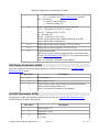
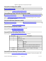
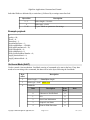
Get Network Parameters (0x1D)
Generates a Current Network Parameters (0x49) packet.
Header 1
Header 2
Length
Type
NIC Index
Checksum
0x51
0xAC
0x03
0x1D
NN
MM
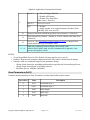
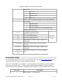
Set SD Card Recording Parameters (0x1E)
NOTE: Recording of video and commands to SD Card is not available on the SLA-2000.
Modify recording parameters for on board video and other data recording to secure digital card. For
SnapShot recording see Set SnapShot (0x5E).
Byte offset
Description
2
Length = 11 + Length of label (see Byte 12)
3
Type = 0x1E
Modify Recording State
4
0
Don't Change State
1
Start Recording
(requires mode (byte 10) and filename (byte 12))
2
Stop Recording
3
Enable network debug trace of commands and responses
4
Disable network debug trace of commands and responses
5
Enable network debug trace of telemetry
6
Disable network debug trace of telemetry
Copyright © 2014-2015 SightLine Applications, Inc.
Page 36 of 95
Jan 15, 2015
SightLine Applications Command and Control
Clear Flash
5
6
0
Don't clear
1
Clear flash. If a recording is in progress, it will be stopped.
2
If a file name is specified, only that file will be deleted.
Reserved
Get Directory
0
Don't get directory
7
1
Get directory information.
(See Current SD Card Directory Contents (0x59))
If a file name is specified (byte 12), it will be interpreted as
a path (SLA-1500 only?)
8&9
Reserved
Record Type – specified as bits, but only commands and telemetry
can be recorded together.
10
0x01
H.264
0x02
JPEG
0x04
Commands (file name will have .log appended)
0x08
Output Telemetry (all platforms)
0x10
Pass-through log file – log data sent by Command Passthrough (0x3D) to an SD card file.
11
Reserved
12
Length of FileName or a path
Set to 0 if no label is necessary.
[OPTIONAL] FileName or path name
13...13+labelLength-1 When recording a video, file extension “.ts” is added to the file name.
This video can then be played back in VLC.
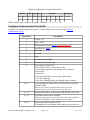
FILE NAMING:
If FileName ends with non-numeric characters, file will save to <FileName>_NNNN.ts where NNNN
is an incrementing count, starting at 0. If FileName ends with a numeric character (0-9), file will save
to <FileName>.ts
If you use
And then Do Snap You should see... Note
FileName...
(0x60)...
Hello
Hello_0000.ts
Count starts at 0
Hello
Hello_0001.ts
Count increments
World
World_0000.ts
Count restarts when FileName changes
Copyright © 2014-2015 SightLine Applications, Inc.
Page 37 of 95
Jan 15, 2015
SightLine Applications Command and Control
Hello42
Hello42.ts
Count is not appended for FileName
ending in a numeric character.
NOTE: The file name count resets to 0 on power up. Files will be overwritten if you use the
same base file name after a power cycle.
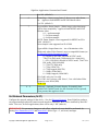
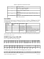
Example 1: Record commands to MicroSD
Start recording Commands to MicroSD
0
1
2
3
4
5
6
7
8
9
10
11
12
13 - 17
0x51 0xAC 0x10 0x1E 0x01 0x00 0x00 0x00 0x00 0x00 0x04 0x00 0x05 hello
18
chksum
Stop Recording Command
0
1
2
3
4
5
6
7
8
9
10
11
12
13
0x51 0xAC 0x0B 0x1E 0x02 0x00 0x00 0x00 0x00 0x00 0x00 0x00 0x00
chksum
At this point the video file hello_0000.ts will found on the MicroSD card.
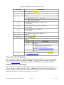
Example 2: Get the Directory Contents of the MicroSD Card
0
1
2
3
4
5
6
7
8
9
10
11
12
13
0x51
0xAC
0x0B
0x1E
0x00
0x00
0x00
0x01
0x00
0x00
0x00
0x00
0x00
0x05
NOTES:
•
System may stall for several seconds while writing video file to MicroSD Card when the STOP
RECORDING command is issued.
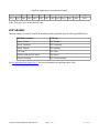
Set Video Mode (0x1F)
Configures capture and display options.
Byte offset
Description
2
Packet length = 16 (or 24 for 3000)
3
Type = 0x1F
4
This parameter is ignored. Number of Input Camera channels (15) – hardware determines the number.
5
This parameter is ignored. Display Destination determines the
value for number of network outputs.
3000: this parameter must be 0.
Copyright © 2014-2015 SightLine Applications, Inc.
Page 38 of 95
Jan 15, 2015
SightLine Applications Command and Control
6
Display Modes
Value
0
One UP
1
Picture In Picture
2
Two Up
3
Quad Screen
4
Blended (see also Set Blend Parameters (0x2F))
5
Stitch
6
Side-By-Side
8
NTSC_VBI (SLA-1500,2000 only)
9
NTSC_VBI and Network (SLA-1500,2000 only)
10– 15
7
9 – 11
12
Copyright © 2014-2015 SightLine Applications, Inc.
Reserved
Display Destination
3000: ignored if packet length > 16
0,1
8
Description
Analog Video
2
Network
3
Analog and Network
4
HD-SDI 720P (SLA-2100 only)
5
HD-SDI 1080P (SLA-2100 only)
6
HD-SDI 1080I (SLA-2100 only)
7 – 15
Reserved
0x80
3000: Secondary Network (Net1)
Camera Stabilize Order (cam0: primary camera)
2000: Camera Stabilize Order (cam1~3)
1500/3000: ignored
PiP Scale
0 = don't change
1
1=
screen size thumbnail of full screen
4
3
2=
screen size thumbnail of full screen
8
1
3=
screen size thumbnail of full screen
2
1
4=
screen size zoom on primary track NEW 2.17
4
Page 39 of 95
Jan 15, 2015
SightLine Applications Command and Control
3
screen size zoom on primary track NEW 2.17
8
1
screen size zoom on primary track NEW 2.17
2
5=
6=
13
PiP Quadrant
Value
Description
0
Top Right
1
Bottom Right
2
Bottom Left
3
Top Left
14-17
Camera Display Order
18-19
3000 only: [Optional] Display Destination for Cam0
20-21
3000 only: [Optional] Display Destination for Cam1
22-23
3000 only: [Optional] Display Destination for Cam2
24-25
3000 only: [Optional] reserved
Copyright © 2014-2015 SightLine Applications, Inc.
Page 40 of 95
Jan 15, 2015
SightLine Applications Command and Control
Display Modes
Illustration 1: Display Modes
Illustration 2: Picture-In-Picture Scale
Illustration 3: Picture-In-Picture Quadrant
Camera Display Order
Defines the order in which cameras will be displayed for display mode. For Example:
0
1
1
0
Display order 0,1,2,3
Display Order 1,0,2,3
When using BLEND mode, the first field for Camera Display Order value should be set to “8”. This
indicates that the primary display index will be used as the final blended result destination image. For
example:
Display
Mode
Display
Dest
0x04
0x01
...
.Camera Order
0x00
0x01
0x02
0x03
...
Camera Display Order
0x08
0x01
0x02
0x03
Set Video Enhancement Parameters (0x21)
Set parameters of the video analog-to-digital converter.
Copyright © 2014-2015 SightLine Applications, Inc.
Page 41 of 95
Jan 15, 2015
SightLine Applications Command and Control
Byte offset
Description
2
Packet length = 6
3
Packet type = 0x21
4
Enhancement Mode
Bits 0..3
Enhancement filter mode:
0 = None (default)
1 = CLAHE
2 = LAP
Bits 4..7
Sharpening:
0 (none)..15 (max)
5
Alpha blending term 0..255 (200 nominal):
0 = use input frame only
128 = 50/50 mix
255 = use filtered frame only)
6
Enhancement Parameter (Kernel)
Bits 0..6
0..127
None: not used
CLAHE: contrast limit (typical 25)
LAP: width of high pass kernel,
clipped to 0..18. (typical 10)
Bit 7
7
Limit Color. Limits the color near edges
where aliasing effects might be scene.
Denoising coefficient (by running average):
0 = No denoising (default)
128 = 50/50 mix
255 = maximum averaging
Set H.264 Video Parameters (0x23)
Modify H.264 output behavior. See also Set Ethernet Display Parameters (0x29) to set the receiver IP
address, Set Metadata Frame Data Values (0x15) to set KLV meta-data and Set Ethernet Video
Parameters (0x1A) to change Down Sample and Frame Step. See also Current H.264 Video
Parameters (0x56).
Byte offset
Description
2
Packet length = 11 (or 13 for 3000)
3
Packet Type = 0x23
4–7
8
Target Bit Rate (bits per second) [ LSB ] (Default 1500000)
Intra Frame (I-frame) Interval (frames) (Default 30)
Copyright © 2014-2015 SightLine Applications, Inc.
Page 42 of 95
Jan 15, 2015
SightLine Applications Command and Control
9
Bits 0..3
0 = Filter All Edges (Default)
1 = Disable All Filtering
2 = Disable Slice Edge Filter
Other values = Reserved
Bits 4..6
Reserved, set to 0
Bit 7
0 = Default
1 = Apply encoder fix to support hardware decoders (SLA1500 only, SLA-2xxx set to 0)
10
Adaptive Intra Refresh AIR Mega-Block Period (frames) * (Default 0)
11
Slice Refresh Row Number – number of rows to coded as each intra-slice*
(Default 0)
12
Reserved – See Set Ethernet Video Parameters (0x1A) to change Down
Sample and Frame Step for Ethernet video.
13 - 14
3000 only: [Optional] Network Display ID (0x0002=Net0,
0x0040=Net1,0x0042=both, else the command will be ignored), if not
present, then applies to both
NOTES:
• To use Mega-Block Period or Slice Refresh, I-Frames must be set to zero (0).
• Problem: Target bit rate parameter changes don't take affect unless I-frame interval changes.
• Solution: when user commands target bit rate parameter change:
◦ Change iframe interval to something random and set target bit rate to desired target bit rate
◦ Change iframe interval back to old iframe interval.
◦ Maximum bit rate: 10MBits (10000000)
Save Parameters (0x25)
Commits current parameters to flash. Parameters are then loaded when system restarts.
Byte offset
Value
0
0x51
fixed header byte 1
1
0xAC
fixed header byte 2
2
0x02
Packet length
3
0x25
Packet Type
4
0x42
Checksum
Copyright © 2014-2015 SightLine Applications, Inc.
Description
Page 43 of 95
Jan 15, 2015
SightLine Applications Command and Control
Get Parameters Function (0x28)
The value of the ID field corresponds to the “Setter” of the same type. Response packets are unique
and have their own ID.
Name
Header
Length Type
ID
Checksum
Get Version Number
0x51 0xAC
0x03
0x28 0x00
0x73
Get Configuration (3000 only *2)
0x51 0xAC
0x03
0x28 0x01
0x2d
Set Stabilization Parameters
0x51 0xAC
0x03
0x28 0x02
0xcf
Set Overlay Mode
0x51 0xAC
0x03
0x28 0x06
0xae
Set Tracking Parameters
0x51 0xAC
0x03
0x28 0x0C
0xd0
Set Coordinate Reporting Mode
0x51 0xAC
0x03
0x28 0x0B
0x53
Set Registration Parameters
0x51 0xAC
0x03
0x28 0x0E
0x6c
Set Video Parameters
0x51 0xAC
0x03
0x28 0x10
0xee
0x51 0xAC
0x03
0x28 0x18
0x2c
0x51 0xAC
0x03
0x28 0x1A
0x90
Set Video Mode
0x51 0xAC
0x03
0x28 0x1F
0xaf
Set Video Enhancement Parameters
0x51 0xAC
0x03
0x28 0x21
0x0e
0x51 0xAC
0x03
0x28 0x23
0xb2
Set Stitch Parameters
0x51 0xAC
0x03
0x28 0x2B
0x70
Set Moving Target Detection Parameters
0x51 0xAC
0x03
0x28 0x2D
0xad
Set Blend Parameters
0x51 0xAC
0x03
0x28 0x2F
0x11
Get Image Size
0x51 0xAC
0x03
0x28 0x31
0x93
Set Ethernet Display Parameters (*1)
0x51 0xAC
0x03
0x28 0x29
0xcc
Set SnapShot
0x51 0xAC
0x03
0x28 0x5E
0xb7
Set Parameter Block
0x51 0xAC
0x03
0x28 0x69
0x8a
Get Hardware ID
0x51 0xAC
0x03
0x28 0x50
0xa8
System Type
0x51 0xAC
0x03
0x28 0x63
0xf4
Set ADC Parameters
Set Ethernet Video Parameters
Set H.264 Video Parameters
(*1)
(*1)
(*1)
SLA-3000 Only
SLA-3000 takes an additional parameter in the following sub commands:
• Set Ethernet Display Parameters (0x29)
• Set H.264 Video Parameters (0x23)
• Set Ethernet Video Parameters (0x1A)
The packet format is shown below:
Copyright © 2014-2015 SightLine Applications, Inc.
Page 44 of 95
Jan 15, 2015
SightLine Applications Command and Control
Byte offset
2
Packet length = 3 (or 5 for 3000)
3
Type = 0x28
4
ID (0x1A, 0x23, or 0x29)
5–6
(*2)
Description
3000 only: [Optional] Network Display ID (0x0002=Net0,
0x0040=Net1), if not present, then Net0 is assumed
Get Configuration (3000 only)
This packet gets sent from SLA-3000 as a response to the Get Parameter / Get Configuration
command.
Byte offset
Description
2
Packet length = 14
3
Type = 0x01
4
Max number of camera inputs (always 3)
5 –7
Reserved
8 – 11
Camera present bit pattern, bit0=Cam0, bit1=Cam1,... (e.g.
0x00000005 indicates Cam0 and Cam2 are connected)
12 – 15
Display present bit pattern (e.g. 0x00000083 indicates Analog,
Net0 and Net1 are available).
See “Display Destination” in Set Ethernet Display Parameters
command for display type values.
Set Ethernet Display Parameters (0x29)
Sets destination IP address and port number. Indicates whether address is Unicast or Multicast.
Configures output format of Ethernet Video.
Byte offset
Description
2
Packet length = 9 (or 11 for 3000)
3
Type = 0x29
4
Bits
0..3
Description
Video Mode
0 RTP MJPEG (default)
1 H.264
2 RTP MJPEG Source
Copyright © 2014-2015 SightLine Applications, Inc.
Page 45 of 95
Jan 15, 2015
SightLine Applications Command and Control
sends compressed source input image
3 H.264 (HD) – SLA-1500 only
3 - 14 Reserved
15 None
4..6
Reserved, set to 0
7
Broadcast Ethernet video
0 Disable Broadcast Video (default)
1 Enable Broadcast (e.g. 255.255.255.255)
Note setting this option may interact strongly with
other network traffic. Use with caution.
Affects H.264 video ONLY.
5–8
IP Address
9 – 10
Base Port Number
11 – 12
3000 only: [Optional] Network Display ID (0x0002=Net0,
0x0040=Net1, else the command will be ignored), if not present,
then applies to both (Net1 uses Base Port Number + 1 in the case)
Example:
Tell the SLA-HARDWARE to send RTP-MJPEG video to IP address 192.168.1.140 on port 5004.
Header
LEN TYPE MODE
0x51 0xAC 0x09 0x29
0x00
IP Address
Port
CHK
0xC0 0xA8 0x01 0x8c 0x8c 0x13 0x5B
192
168
1
140
5004
Set Display Adjustments (0x2A)
Set the parameters for fine-tuned adjustments of the display.
Byte offset
Description
2
Packet length = 8
3
Packet type = 0x2A
4,5
Ratio of secondary to primary imager zoom levels multiplied by
256
6, 7
Display pan column offset in pixels (-32768 to 32767). Signed
16-bit integer
8, 9
Display tilt row offset in pixels (-32768 to 32767). Signed 16-bit
integer
Copyright © 2014-2015 SightLine Applications, Inc.
Page 46 of 95
Jan 15, 2015
SightLine Applications Command and Control
Set Stitch Parameters (0x2B)
Set the parameters for image stitching mode. Requires Set Video Mode (0x1F) be used to set number
of camera inputs to 2, display to Network Mode.
Byte offset
Two raw images
Description
2
Packet length = 10
3
Packet type = 0x2B
4
Reserved = 0
5
Shift camera one up. (0 … 255) number of pixels
6
Shift camera one right. (0 … 255) number of pixels
7
Shift camera one down. (0 … 255) number of pixels
8
Shift camera one left. (0 … 255) number of pixels
9
Reserved = 0
10
Reserved = 0
11
Reset calibration. (1 = = reset, 0 = = don't)
Right Images is shifted The maximum overlap is Final image is displayed
relative to the left
calculated
in a 1280x480 window
Set Moving Target Indication Parameters (0x2D)
Set the parameters for Moving Target Indication (MTI). Results in Current Tracking Positions (0x51)
results being generated. See also Set Coordinate Reporting Mode (0x0B).
Four modes of automatic moving target indication are available, depending on the security bits enabled.
1. Vehicle Medium Moving Target Indication. This mode works best when finding moving
vehicles in a moving scene. It works well from a moving aerial platform for finding vehicles
that are typically 10 to 100 pixels long in the scene. It does not work as well at finding very
small, very large, slow or erratically moving objects.
2. Staring Small Moving Target Indication. This mode works well when the camera is either
stationary or moves then stares for extended times at a scene. It can find objects that are small
and move at slow, fast or varying rates or that temporarily stop.
3. Full Mobile Small Moving Target Indication. This mode works from a moving platform and
can find small and slow or fast or erratically moving objects. It is capable of handling scene
motion that with significant perspective change. It will lose objects that stop moving. This
Copyright © 2014-2015 SightLine Applications, Inc.
Page 47 of 95
Jan 15, 2015
SightLine Applications Command and Control
mode takes the most compute resource and is the most likely to run at less than full frame rate if
other processing is also enabled (such as network video output).
4. Mobile Small Moving Target Indication. This mode works well when the camera is either
stationary or slowly moving. It can find objects that are small and move at slow, fast or varying
rates of speed. It will lose objects that stop moving. This technique is similar to Full Mobile,
but it can not handle large perspective changes and it requires less compute resource.
Byte offset
Description
2
Packet length = 8
3
Packet type = 0x2D
4
0 = Don't change motion modes
Note: Only choose one of bits 4 (MTD), 5 (Staring MTI), 6
(Mobile MTI).
Bit 0
1 = Disable All (Other bits ignored)
Bit 1
Reserved
Bit 2
0 = Disable motion assist of primary target
1 = Enable motion assist for primary target only
Bit 3
0 = Disable motion assist of all targets
1 = Enable motion assist for all targets
Bit 4
Vehicle Medium Moving Target Indication – for
use on a mobile platform
0 = Disable, 1 = Enable
Note: if enabled, tracking mode will be set to
vehicle tracking.
Bit 5
Staring Camera Small Moving Target Indication for use with a fixed camera or a camera that moves
then “stares”.
0 = Disable, 1 = Enable
Bit 6
Full Mobile Platform Small Moving Target
Indication – for a
0 = Disable, 1 = Enable
Bit 7
Mobile Platform Small Moving Target Indication –
for a fixed or slowly moving camera
0 = Disable, 1 = Enable
5
0 = Disable moving target debug display (default)
1 = Enable moving target debug display
6
Sensitivity
0 = Don't change sensitivity value.
1...10 Set sensitivity value. 1 = highest sensitivity 10 = lowest
Copyright © 2014-2015 SightLine Applications, Inc.
Page 48 of 95
Jan 15, 2015
SightLine Applications Command and Control
sensitivity. Default is 5.
The moving target indication sensitivity refers to the algorithm's
“threshold” for deciding whether a particular candidate moving
target is a moving target or a false positive. A lower value
translates into greater sensitivity to moving targets and faster
detection time, but also may introduce more false positives. A
higher value translates into less sensitivity to moving targets,
higher detection time for a given candidate, but less false
positives.
7
Small target MTI Threshold.
(Not used in Vehicle MTI mode)
This is an advanced parameter. It controls the threshold at which
potential moving targets are generated. The sensitivity
parameter controls MTI threshold when this parameter is set to 0.
Otherwise, it overrides the sensitivity parameter (byte 6).
8
Small target MTI Watch Frames.
(Not used in Vehicle MTI mode)
This is an advanced parameter. After a potential moving target is
generated by the moving target indication system, it is watched
by the system for a number of frames. This controls the number
of frames the system watches a moving target before displaying
it. The sensitivity parameter controls MTI watch frames when
this parameter is set to 0. Otherwise, it overrides the sensitivity
parameter (byte 6).
9
Reserved
Set Advanced Moving Target Indication Parameters (0x76)
BETA 2.20 This packet provides beta level control of advanced MTI parameters. It is expected that
this packet will change in subsequent releases.
Byte Name
Offset
Type Description
2
Length
u8
Packet length = 39
3
Type
u8
Packet type = 0x76
MinVel8
s16 Minimum target velocity (256*pixels/frame) (-1 = not set)
MaxVel8
s16 Minimum target velocity (256*pixels/frame) (-1 = not set)
MaxAccel8
s16 Maximum target acceleration (256*pixels/frame2) (-1 = not set)
MinWide
s16 Minimum target width (pixels) (-1 = not set)
Copyright © 2014-2015 SightLine Applications, Inc.
Page 49 of 95
Jan 15, 2015
SightLine Applications Command and Control
MaxWide
s16 Maximum target width (pixels) (-1 = not set)
MinHigh
s16 Minimum target height (pixels) (-1 = not set)
MaxHigh
s16 Maximum target height (pixels) (-1 = not set)
MaxThresh
u8
Maximum automatic threshold (0 to 255 grey levels). A lower level
results in higher sensitivity, but more false detects.
NFramesBack
u8
Number of frames to go back in time to compare frames in MTI
difference mode. (1 to 15). Default 15.
MergeRadius
u8
Maximum distance between targets at which they can be merged
into a single target. (0 to 255 pixels) 0 = automatic, default = 0,
typical is 10 to 25.
MergeDirTol
u8
Maximum angle heading difference between targets at which they
can be merged. (0 to 180 degrees). Default = 45 degrees.
NWatch
u8
Number of frames to watch a “blob” before it moves to “peak” state.
PkNWatch
u8
Number of frames to watch a “peak” before it moves to “track”
state.
SuspScore16
s16 “Blob” with a “suspicious” score above this value are not eligible to
move to “peak” state. Default 6554.
BgTimeConst
u16 Time constant (in frames) at which frames are averaged into the
background model. At the default value of 600, the background will
mostly be replaced after about 20 seconds.
BgEdgePenalty6
u8
Penalty to apply to edges in background model mode. Typical
values are 0 (no edge penalty) to 64 (full edge penalty). Default 64.
BgResetConf
u8
Reset background model if registration confidence falls below this
value for BgResetFrames frames. 0 to 100, default 60
BgResetOff
u8
Reset background model if the registration column or row offset
exceeds this value for BgResetFrames frames. 0 to 255, default 100
BgResetAng
u8
Reset background model if the registration angle in degrees exceeds
this value for BgResetFrames frames. 0 to 180, default 5
BgResetFrames
u8
Reset background model if the above conditions are met for this
number of consecutive frames. 0 to 255, default 3. Allows for
recovery from temporary bad frames or temporary large motion, but
resets when there is a large amount of motion.
BgWarpConf
u8
Warp the background model if registration confidence falls below
this value for BgWarpFrames frames. 0 to 100, default 80
BgWarpOff
u8
Warp the background model if the registration column or row offset
exceeds this value for BgWarpFrames frames. 0 to 255, default 50
BgWarpAng
u8
Warp the background model if the registration angle in degrees
Copyright © 2014-2015 SightLine Applications, Inc.
Page 50 of 95
Jan 15, 2015
SightLine Applications Command and Control
exceeds this value for BgWarpFrames frames. 0 to 180, default 1
BgWarpFrames
u8
Warp the background model if the above conditions are met for this
number of consecutive frames. 0 to 255, default 2. Allows for
ignoring a small number of bad frames or temporary large motion,
but warps when there is a significant amount of motion.
MaxTrackFrames
u16 Number of frames to keep tracking once target has disappeared. 0
to 65535. 0 = automatic.
DisplayIndices
u8
1 = show indicies with targets, 0 = don't. TODO, use
Set Blend Parameters (0x2F)
Requires Set Video Mode (0x1F) be used to set Display Modes to Blend. See also Current Blend
Parameters (0x4D).
NEW 2.20 – Blend an EO (visible) and an IR camera. The EO camera can now be an HD digital
camera. The EO camera will always be the camera that “warps” into the space of the IR camera to
produce the output image.
When both cameras are standard definition with similar fields of view, set Absolute Zoom Mode off to
scale the EO camera to match the IR. When the EO camera is HD, Absolute Zoom Mode can be turned
on to achieve a more significant zoom factors. For example, if a 1280x720 HD camera is to be blended
with a 640x480 camera where the horizontal fields of view match, pass zoom=128 and zoom absolute
= 1 to get a zoom factor of 0.5 which will scale the HD image to 640x360 before blending.
Copyright © 2014-2015 SightLine Applications, Inc.
Page 51 of 95
Jan 15, 2015
SightLine Applications Command and Control
Byte offset
Description
2
Packet length = 17
3
Packet type = 0x2F
Bit 0
Offset Mode (see examples below)
0 Interpret bytes 5&6 as incremental offsets
1 Interpret bytes 5&6 as absolute offsets
Bit 1
Absolute Zoom Mode NEW 2.20
0 Zoom (1 … 255) maps to (0.9 … 1.1). Usually used
when both cameras are SD or have matching pixel
size on target.
4
1 Zoom (1 … 255) maps to (0.004 … 0.996). Usually
used when one camera is HD and the other is SD.
Bits 2-7 Reserved
Shift EO camera position vertically.
5
(-128...127) number of pixels.
Negative number = up
Positive number = down
Shift EO camera position horizontally.
6
7
8
(-128...127) number of pixels.
Negative number = left
Positive number = right
Rotation of EO camera (1 … 255) maps to (-5 … 5) degrees
0 = don't change rotation (default)
Zoom scale factor applied to EO camera (1 … 255). Maps to
(0.9 … 1.1) or to (0.004 to 0.996), depending on Absolute Zoom
Mode in byte 4
0 = don't change zoom (default)
9
Blend mode:
Value
Copyright © 2014-2015 SightLine Applications, Inc.
Description
0
Don't change (default)
1
Frame Blend – basic percentage (controlled by
Amount) blending of the two images, Optionally
applies yellow Hue from bright areas in the EO image
to the output.
2
Thermal Blend – blends hot pixels from the IR camera
Page 52 of 95
Jan 15, 2015
SightLine Applications Command and Control
(shown in red) with the EO image. Typically used to
highlight hot areas in a daytime EO image.
3
Night Blend – blends bright areas from the EO camera
(modify color with Hue) with the IR image. Typically
used to highlight bright lights in a night time IR image.
4
Color Blend - percentage (controlled by Amount)
blending of the two images like Frame Blend, but the
color from the EO image is also passed to the output
(also controlled by Amount).
Amount defines the amount of luminance information from the
EO (visible) camera to include in the blended result.
10
0 = don't change/default.
(1 … 255) maps to (0 … 1).
Applies to: FrameBlend, NightBlend, ColorBlend and
ThermalBlend modes.
Hue scale factor. Amount of yellow hue to apply from bright
areas in the EO camera.
0 = No Change
11
1 = No Hue
...
255 = Full Hue
Applies to: FrameBlend and NightBlend modes.
12
Reserved (set to 0)
13
Calibration reset (0 or 1). Resets the image warp calibration
(zoom, rotate, shift up/down/left/right) back to default.
14
Reserved (set to 0)
15
EO camera index (0 to 4, default 1). This camera is warped into
the space of the other camera through the calibrations settings
before blending. It is assumed that this is the EO or visible
camera input for Thermal and Night blend modes. MOD 2.20.7
16
IR camera index (0 to 4, default 0). This camera is not warped
before blending. It is assumed that this is the IR or infrared
camera input for Thermal and Night blend modes. MOD 2.20.7
17
Image Alignment Parameter Index NEW 2.20
Copyright © 2014-2015 SightLine Applications, Inc.
0
Use the alignment parameters in this packet (default)
1
Use a preset alignment (defined by Set Multiple
Alignment (0x74)) and set index of preset alignment
Page 53 of 95
Jan 15, 2015
SightLine Applications Command and Control
parameters in byte 18 below.
Indicate index of preset alignment parameters. This byte ignored
if byte 17 above is set to zero. NEW 2.20
18
Offset Mode Examples
If byte 4 is 1, then field is interpreted as absolute offset
e.g. new EO horizontal offset (relative to EO image) = byte 5
If byte 4 is 0, then field is interpreted as incremental offset
e.g. new EO vertical offset (relative to EO image) = old IR vertical position + byte 5
Designate Selected Track Primary (0x32)
Command the system to designate the selected track as primary.
Header 1
Header 2
Length
Type
Checksum
0x51
0xAC
0x02
0x32
0x5C
Shift Selected Track (0x33)
Command the system to shift the selected track to the next track. See Designate Selected Track Primary
(0x32) and
Header 1
Header 2
Length
Type
Checksum
0x51
0xAC
0x02
0x33
0x02
Set Acquisition Parameters (0x37)
Configure video input for digital camera interfaces.
NOTE: For changes between NTSC and PAL camera mode to take effect, a board soft reset should be
performed, by issuing Save Parameters (0x25) and Reset (0x01) (Reset Type = 2, soft reset) messages.
NOTE: systems cannot support different analog video formats on different analog ports. For
example, when one analog video port is set to NTSC, all of the analog video ports are set to NTSC.
Byte offset
Description
2
Length = 15
3
Type = 0x37
4
Video Port Index
Board
Copyright © 2014-2015 SightLine Applications, Inc.
Page 54 of 95
Analog Ports
Digital Port
Jan 15, 2015
SightLine Applications Command and Control
5
SLA-2000
0 to 3
4
SLA-2100
0 and 1
2
SLA-1500
0 and 1
2
Video Port Types (SLA-2000/2100)
Video Port Types (SLA-1500)
6–7
High (pass 0 for default)
NOTE: High, Wide and Bit Depth are ignored except in Generic
Digital Mode.
8–9
Wide (pass 0 for default)
10
Bit Depth (pass 0 for default)
11 – 12
Vertical Front Porch in Lines (pass 0 for default) (SLA1500)
13 - 14
Horizontal Front Porch in Pixels (pass 0 for default) (SLA1500)
15 - 16
Flags – configuration parameters (pass 0 for default) (SLA1500)
Bits 0..2
Input Data Mode
0=Greyscale
1= YUV
Others = Reserved
Copyright © 2014-2015 SightLine Applications, Inc.
Bit 3
Interlaced (1=interlaced)
Bit 4
VSync Polarity (1 = inverted) (for Sony 7500)
Bit 5
HSync Polarity (1 = inverted) (for Sony 7500)
Bits 6..9
Init code – calls camera initialization routine.
Called with parameters specified above in this
message
0 = no-op
1= InitSony(High)
2=InitDRS(Bit Depth)
3=InitTau(Bit Depth)
Bits 10
Use Data Valid signal (SLA-3000)
Bits 11..15
Reserved
Page 55 of 95
Jan 15, 2015
SightLine Applications Command and Control
Video Port Types (SLA-2000/2100)
Port ID
0
1
2
3
4
5
6
7
8
9
10
11
12
13
14
15
16 – 255
Description
Disabled
Hardware Support
NOTE: Save parameters and reset to change
between PAL and NTSC.
NOTE: Sets all analog camera ports to NTSC.
SLA-2000 CameraLink
Generic Digital
NOTE: Uses High, Wide, and Bit Depth
Sentech CL33A
SLA-2000 CameraLink
Goodrich SU640HSX
SLA-2000 CameraLink
Nova Eagle MWIR 640 SLA-2000 CameraLink
Sentech STC-HD133DV SLA-2000 Digital
720P
SLA-2100 HD-SDI
1080P
SLA-2100 HD-SDI
1080I
SLA-2100 HD-SDI
FLIR TAU 640 8 Bit
SLA-2000 CameraLink
FLIR TAU 640 14 Bit
SLA-2000 CameraLink
Goodrich SU640HSX
SLA-2000 CameraLink
(no serial control)
NOTE: Save parameters and reset to change
PAL
between PAL and NTSC.
NOTE: Sets all analog camera ports to PAL.
Reserved
HD Hitachi 720 P
Hitachi Block camera NEW 2.20
Reserved
NTSC
Copyright © 2014-2015 SightLine Applications, Inc.
Page 56 of 95
Jan 15, 2015
SightLine Applications Command and Control
Video Port Types (SLA-1500)
Port ID
Description
0
Disabled
1
NTSC (Auto)
2
Generic Digital
3–6
7
8
9
10
11
12
13
14
15
16
17
18
19
20
21
22
23
24
25 – 255
Reserved
720P
1080P
1080I
FLIR TAU 640 8 Bit
FLIR TAU 640 14 Bit
Reserved
PAL
Reserved
HD Hitachi 720 P
DRS Tam 640 8 bit
DRS Tam 640 14 bit
DRS Tam 320 8 bit
DRS Tam 320 814 bit
Alticam Barracuda 600P
HD-SDI 720P 30
NTSC VBI
HD SONY 7500 720P 30
HD SONY 7500 1080P 30
Reserved
Hardware Support
Automatically detect NTSC or PAL. Defaults to NTSC if no
analog camera is connected. Analog video output type is
matched to analog video input type.
NOTE: Save parameters and reset to switch between PAL/NTSC.
NOTE: Sets all analog camera ports to NTSC.
Generic Digital Interface.
NOTE: Uses High, Wide, Bit Depth, Vertical and Horizontal
Front Porch, Flags
SONY 6000 series, 3150
SONY 6000 series
SONY 6000 series
NEW 2.19 Forces analog video input and output to PAL mode.
NOTE: Save parameters and reset to switch between PAL/NTSC.
NOTE: Sets all analog camera ports to PAL.
Hitachi Block camera
DRS Tamarisk 640
DRS Tamarisk 640
DRS Tamarisk 320
DRS Tamarisk 320
Alticam Barracuda
NTSC camera with VBI data
Sony 7000 series*
Sony 7000 series*
* NOTE: Sony 7000 series, camera requires a power cycle when changing between 720 and 1080
mode.
Copyright © 2014-2015 SightLine Applications, Inc.
Page 57 of 95
Jan 15, 2015
SightLine Applications Command and Control
Get Acquisition Parameters (0x38)
Get video port configuration. Causes a Current Acquisition Parameters (0x4F) message to be sent.
Byte offset
Description
2
Length = 3
3
Type = 0x38
4
Video Port Index
Draw Object (0x3B)
Draw user specified overlay graphics on the screen.
All coordinates in this message are specified in with the center of the image at (0, 0) and the upper left
corner at (-image width/2, -image height/2).
Byte offset
Description
2
Packet length = 15 (for non-text objects), variable for text
object types (>15)
3
Packet Type = 0x3B
4
Unique Object ID (1 to 255), refer to this ID to destroy a created
graphic object.
ID=0 is used for destroying all objects when Action=Destroy.
5
Action
0 = Destroy
1 = Create
Note that if destroy action is specified, then fields following this
are ignored.
6
Copyright © 2014-2015 SightLine Applications, Inc.
Coordinate Properties
Value = 0
Reserved
Value = 1
Coordinates are specified in source coordinate
space. In addition, draw object is moved with
camera motion. This mode is useful for overlays
such as laser reticles.
Value = 2
Coordinates are specified in display coordinate
space. In addition, draw object is moved with
scene motion. This mode is equivalent to scene
mode tracking with a custom overlay.
Value = 3
Reserved
Page 58 of 95
Jan 15, 2015
SightLine Applications Command and Control
Value = 4
Reserved
Value = 5
This mode should be used for static overlays such
as text.
Bit 7
If bit 7 = 0, then coordinates are specified with the
center of the image at (0, 0). This means that the
upper-left corner is at (-display width/2, -display
height/2) or (-source width/2, -source height/2)
depending on the coordinate mode.
If bit 7 = 1, then coordinates are specified with the
upper left corner of the image at (0, 0). This
means that the center of the image is at (display
width/2, display height/2) or (source width/2,
source height/2) depending on the coordinate
mode.
7
Object Type
0 = Circle
1 = Rect
2 = Line
3 = Text
4 = FilledCircle
5 = FilledRect
6 = TextEx
8&9
Object
Interpretation
Circle, FilledCircle Center Point X-Coordinate
Rect, FilledRect
Upper Left Corner X-Coordinate
Line
End Point 1 X-Coordinate
Text, TextEx
Upper Left X-Coordinate
10&11
Object
Interpretation
Circle, FilledCircle Center Point Y-Coordinate
Rect, FilledRect
Upper Left Corner Y-Coordinate
Line
End Point 1 Y-Coordinate
Text, TextEx
Upper Left Y-Coordinate
12&13
Object
Interpretation
Circle, FilledCircle Radius
Copyright © 2014-2015 SightLine Applications, Inc.
Rect, FilledRect
Width
Line
End Point 2 X-Coordinate
Page 59 of 95
Jan 15, 2015
SightLine Applications Command and Control
Text
Length of the text string (referred to as
“length” below)
TextEx
[12] = horizontal scale shifted left 5 (e.g.
32 means no scaling. 0 is also interpreted
as no scaling).
[13] = vertical scale shifted left 5
14&15
Object
Interpretation
Circle, FilledCircle Ignored
16
Rect, FilledRect
Height
Line
End Point 2 Y-Coordinate
Text
Ignored
TextEx
[14] = font ID (0=default, 1=bold font,
4=classic font)
[15] = font spacing (pixels between a font
to the next font. If 0, then uses the font's
default spacing)
Color (See Table below for color to number mappings)
17 to 17+length-1
Bits 0-3
Background color. NEW 2.17 for vertical
and lines, the background color is drawn as
a shadow. Pass Transparent (14) to disable
drawing of shadow
Bits 4-7
Foreground
Text Object Only: Text string characters
Color To Number Mapping:
Value
Description
Value
Description
0
White
8
Light Green
1
Black
9
Green
2
Light Gray
10
Dark Green
3
Gray
11
Red
4
Dark Gray
12
Orange
5
Light Blue
13
Yellow
6
Blue
14
Transparent
7
Dark Blue
15
Automatic
Copyright © 2014-2015 SightLine Applications, Inc.
Page 60 of 95
Jan 15, 2015
SightLine Applications Command and Control
Stop Selected Track (0x3C)
Command the system to stop the currently selected track.
Byte offset
Value
Description
2
0x02
Packet length
3
0x3C
Packet type
4
0x43
Checksum
Command Pass-through (0x3D)
Outputs data payload to the port specified. Use Configure Communication Port (0x3E) to setup the
inbound and outbound physical ports.
Byte offset
Description
2
Length = 3 + payload length
3
Type = 0x3D
4
Destination Port ID (see below)
5 – 5 + Payload
Length
Payload
Minimum 1 byte
Maximum 80 bytes
NOTE: actual payload length can be anywhere between 1 and 80 bytes.
NOTE: no assumptions are made on terminating characters such as carriage return (0x0D), line feed
(0x0A), or null (0x00)
Port ID
NOTE: See Hardware specific ICD to see which ports your hardware currently support.
Port ID
0
1
2
3
4
11
Description
Serial Port 0
Serial Port 1
Ethernet Port
Reserved
Serial Port 2
SD Card log file. Start, stop and name this file with Set SD
Card Recording Parameters (0x1E)
Example:
Send a 5 byte payload “HELLO” to serial port 1.
Copyright © 2014-2015 SightLine Applications, Inc.
Page 61 of 95
Jan 15, 2015
SightLine Applications Command and Control
Header
LEN Type Port
Payload
0x51 0xAC 0x08 0x3D 0x01 0x48 0x45 0x4c 0x4c 0x4F
Checksum
0xCB
H
E
L
L
O
Where length = type + dest port + payload + checksum = 1 + 1 + 5 + 1 = 8
Configure Communication Port (0x3E)
Configure one of the communication ports. Current setting can be retrieved using Get Port
Configuration (0x3F).
Byte offset
Description
2
Length = 20
3
Type = 0x3E
4
Destination Port ID (see above, currently must be 1)
5
Baud Rate (see below)
6
Data Bits
7
Stop Bits
8
Parity
9
Maximum packet length
10
Maximum packet delay (ms)
11
Protocol parser: MOD 2.18
0: SLA Protocol (SLA-1500 at Port 0 only)
1: Scan Eagle Aquarius packet parsing & SLA Protocol
2: Reserved 0
3: Reserved 1
4: Port Not Used (allows use by other applications)
5: TCP Pass Through
6: Raw Pass Through (direct pass-through with no change)
12 – 13
Local inbound port number where UDP packets are expected
LSB then MSB
Ethernet port were all payload data will be received.
Hardware opens a new socket to listen on this port.
14 – 17
Destination IP address of host where UDP packets will be sent
18 – 19
Port number where host is listening.
Hardware opens a new socket and sends data to the outbound
destination IP Address at the destination port number.
20-21
AttNav port number (default 65100)
If configured as Pass Through, data on this port is passed on to
Copyright © 2014-2015 SightLine Applications, Inc.
Page 62 of 95
Jan 15, 2015
SightLine Applications Command and Control
the serial port. NEW 2.18
NOTE: Serial ports do not offer hardware or software flow control.
NOTE: For parameter changes to take effect, a board soft reset should be performed, by issuing Save
Parameters (0x25) and Reset (0x01) (Reset Type = 2, soft reset) messages.
KLV Pass-through receives formatted KLV metadata via serial port generated by an external processor.
This KLV metadata is injected into the MPEG2-TS stream along with compressed digital video. When
using this mode, internally-generated KLV metadata should be disabled via Set Metadata Rate (0x62).
Example:
Tell the SLA-HARDWARE to send data received on local port 1000 out on to serial port 2 configured
at 57600 baud, 8 data bits, 1 stop bit, and no parity. Any data received from serial port 2 will be sent to
the IP address of 192.168.1.119 on port 10000. Raw payload data can now be sent directly to the IP
address of the SLA-HARDWARE on port 1234 or data can be sent through the SLA Protocol port
(serial port 0 or Ethernet port 14001) using Command Pass-through (0x3D).
Header
LEN Type Dest Port Baud Data Stop Parity Max Max Parser
0x51 0xAC 0x12 0x3E
0x04
Header
0x03 0x08 0x01 0x00 0x64 0x64
0x02 ...
Serial Port 1 configuration
Inbound Port Outbound/Reply IP Address Outbound Port Checksum
... 0xe8
0x03
1000
0xc0
0xa8
0x01
0xdb
192
168
1
119
0x10
0x27
0xc1
10000
Serial Port Parameters
Baud Rate
Value
Baud Rate
0 4800 (1500 only)
1 9600
2 38400
3 57600 (Default)
4 115200
5 19200
Protocol Parser
Index
0
Name
Description
Ignore
Copyright © 2014-2015 SightLine Applications, Inc.
Page 63 of 95
Jan 15, 2015
SightLine Applications Command and Control
1
Scan Eagle Aquarius
2
FLIR TAU
3
SLA Protocol
(SLA-1500 at Port 0 only)
Get Port Configuration (0x3F)
Results in the generation of either a Current Port Configuration (0x53) or a Current Network
Parameters (0x49).
Byte offset
Description
2
Length = 3
3
Type = 0x3F
4
Destination Port ID (see above)
Set SnapShot (0x5E)
Set up parameters for image snapshot to an FTP server or onboard MicroSD. For viewing a list of
existing files, or recording video see Set SD Card Recording Parameters (0x1E). Image is recorded
from the Camera Order 0 set by Set Video Mode (0x1F). When Image source is set to Capture, image
contents and size will be the same as the raw image from the camera. For example, if using an Analog
Video Source, the image size will be 640x480. If using a digital image from a Sony FCB-EH6300 the
image will be 1280x720. When Image Source is set to Display Image, then the image will be a
640x480 image with all the overlay graphics, digital zoom, and other image processing applied.
•
Instructions to configure an FTP server are available in ApplicationNote_FileZilla.pdf.
•
Instructions for formatting a MicroSD card are in
ApplicationNote_FormattingMicroSDCards.pdf
Byte offset
Description
2
Packet length = 15 + userLen + passLen
3
Packet type = 0x5E
Snapshot Destination
4
0
FTP Server
1
Micro SD Card NEW 2.18
2 – 15
5
Copyright © 2014-2015 SightLine Applications, Inc.
Reserved
Reserved, set to 0
Page 64 of 95
Jan 15, 2015
SightLine Applications Command and Control
Image Source
6
0
Reserved
1
Captured image
2
Display image
3 – 15
7
Reserved
Quality – JPEG compression quality level 0 to 100 (default 80)
Down Sample
8
1
Full Resolution
2
2x2 downsample
4
4x4 downsample (SLA-1500 SD images only)
All other values Reserved
9 – 12
IP ADDRESS of the FTP server.
(dot form, eg. 192 168 1 197)
13
Server Port MSB (default 0)
14
Server Port LSB (default 21)
15
[REQUIRED] Username Length - length of user
name string
FTP ONLY
(Otherwise set
to 0's)
16 - 16+userLen-1 [OPTIONAL] User Name – FTP server login
user name
16+userLen
[REQUIRED] Password Length – length of pass
word string
17+userLen –
[OPTIONAL] Password – FTP server login pass
17+userLen+passLe word
n-1
Do SnapShot (0x60)
Execute an image snapshot to an FTP server or the MicroSD Card. Run Set SnapShot (0x5E) first to
specify the FTP server, login and other SnapShot parameters.
On the SLA-1500-OEM /mnt/mmcblk0p1/ or /mnt/mmcblk0p5/ is automatically prefixed to filename
unless you start filename with “ / ” then no prefix is added and the file may be written to NAND
FLASH. This is not recommended. If directory/path is specified, it will be created if it doesn't exist.
Byte offset
2
Copyright © 2014-2015 SightLine Applications, Inc.
Description
Packet length = 5 + fileNameLen
Page 65 of 95
Jan 15, 2015
SightLine Applications Command and Control
3
Packet type = 0x60
4
Frame Step – step between frames
(e.g. 2 = every other). (default 1)
5
Number of frame snapshots to take.
(default 1)
6
[REQUIRED] File Name Length - length of file name string
(Default 0)
16 - 6+fileNameLen-1
[OPTIONAL - RECOMMENDED] FileName – Base file name of
saved files (see below).
FILE NAMING:
If FileName ends with non-numeric characters, file will save to <FileName>_NNNN.jpg where NNNN
is an incrementing count, starting at 0. If FileName ends with a numeric character (0-9), file will save
to <FileName>.jpg
If you use
And then Do Snap You should see... Note
FileName...
(0x60)...
Hello
Hello_0000.jpg
Count starts at 0
Hello
Hello_0001.jpg
Count increments
World
World_0000.jpg
Count restarts when FileName changes
Hello42
Hello42.jpg
Count is not appended for FileName
ending in a numeric character.
NOTE: The file name count resets to 0 on power up. Files will be overwritten if you use the same base
file name after a power cycle.
EXAMPLE (Single Snap to MicroSD):
Record a single JPEG called “hello_0000.jpg”
HEADER
LEN
TYPE
SRC
Q
SMP
IP ADDRESS
port
0x51 0xAC 0x0F 0x5E 0x01 0x00 0x01 0x50 0x01 0 0 0 0 0x00 0x00
HEADER
LEN
TYPE
Step
numFr
Len
USRLEN PSSLEN
0x00
0x6c
0x00 0xD1
CHK
SUM
Base File Name
0x51 0xAC 0x0a 0x60 0x01 0x01 0x05 0x68 0x65 0x6c
CHK
SUM
0x6f
0x95
File hello_0000.jpg is now on the MicroSD card. Sending the same command...
HEADER
LEN
TYPE
Step
Copyright © 2014-2015 SightLine Applications, Inc.
numFr
Len
Page 66 of 95
Base File Name
CHK
Jan 15, 2015
SightLine Applications Command and Control
SUM
0x51 0xAC 0x0a 0x60 0x01 0x01 0x05 0x68 0x65 0x6c
0x6c
0x6f
0x95
hello_0001.jpg is now on the MicroSD card.
EXIF HEADER:
Snapshot images are created with EXIF metadata headers populated from the following MISB fields:
MISB data element
EXIF tag
Sensor Latitude
GPS Latitude
Sensor Longitude
GPS Longitude
Sensor Altitude
GPS Altitude
UTC Time
GPS Time
Platform Indicated Air Speed
GPS Speed
Platform Heading
GPS Track Direction
See Set Metadata Data Values (0x13) for more information on populating these fields.
Copyright © 2014-2015 SightLine Applications, Inc.
Page 67 of 95
Jan 15, 2015
SightLine Applications Command and Control
Version Number (0x40)
Get Parameters Function (0x28)
Reports software and hardware version numbers.
Get Version Number (0x00)
Byte offset
Description
2
Packet length = 17
3
Packet type = 0x40
4
Software Version Major
5
Software Version Minor
6
Reserved
7
Temperature (degrees F)
8 – 10
Hardware UID
11 – 14
Application Bits (app bits) NEW 2.18 below
15
Hardware Type NEW 2.17 above
16
Software Revision (Release number)
17-18
Other Version (Used for FPGA on SLA1500) NEW 2.20
Application Bits (App Bits)
Bit
Value
Description
0
0x00000001
HD output (1500) NEW 2.20
1
0x00000002
Stabilization
2
0x00000004
H.264 video compression in MPEG2-TS network video output
3
0x00000008
MTI0 – Vehicle, Staring and Mobile moving target indication
4
0x00000010
Tracking of objects
5
0x00000020
MTI1 - Full Mobile moving target indication of small sized objects
6
0x00000040
Telemetry output for gimbal control
7
0x00000080
Enhancement
8
0x00000100
Stitching and blending of multiple images
9
0x00000200
HD input (1500) NEW 2.20
10
0x00000400
Recording of video and snapshot of still images
11
0x00000800
KLV metadata encoding into MPEG2-TS H.264 network video stream
Table 13: Application Bits (App Bits)
Copyright © 2014-2015 SightLine Applications, Inc.
Page 68 of 95
Jan 15, 2015
SightLine Applications Command and Control
Current Stabilization Parameters (0x41)
Get Parameters Function (0x28)
Set Stabilization Parameters (0x02)
Describes the current stabilization mode. See also Set Stabilization Parameters (0x02) and Set
Stabilization Bias (0x12).
Byte offset
Description
2
Packet length = 6
3
Packet type = 0x41
4
Mode (default 9)
Bit
Description
0
0 – Stabilization OFF
1 – Stabilization ON
1
0 – Enable
1 - Disable all registration, stabilization, enhancement
and tracking
2
0 – Previous images background
1 - Black background
3
0 – Auto bias disabled
1 – Auto bias enabled
Bit 4– 6 Reserved
Bit 7 0 – Enable PIP image micro stabilization
1 – Disable PIP image micro stabilization
5
Screen re-centering rate 0..255 (default 50)
6
Limit – maximum stabilization offset in pixels. 0 = no limit.
(default 0)
7
Angle Limit – maximum stabilization rotation angle in degrees.
(default 0)
Current Overlay Mode (0x42)
Get Parameters Function (0x28)
Byte offset
Set Overlay Mode (0x06)
Description
2
Packet length = 5
3
Packet type = 0x42
Copyright © 2014-2015 SightLine Applications, Inc.
Page 69 of 95
Jan 15, 2015
SightLine Applications Command and Control
4
5
6
Bits 0..3
Primary track color mode
Same as primary track color mode, above
Bits 4..7
Primary track reticle type
Same as primary track reticle type, above
Bits 0..3
Secondary track color mode (SLA-2000 only)
Same as primary track color mode, above
Bits 4..7
Secondary track reticle type (SLA-2000 only)
Same as primary track reticle type, above
Bit 0
Overlay cursor. 0 = don't, 1 = do
Bit 1
Overlay track box. 0 = don't, 1 = do
Bit 2
Reserved = 0
Bit 3
Overlay Histogram
0 = don't
1 = do
Bit 4
Overlay track index
0 = don't
1 = do
Bit 5
Show track motion trails
0 = don't
1 = do
Bit 6
Reserved = 0
Bit 7
Show registration ignore edge lines
0 = don't
1 = do
Tracking Position (0x43)
Periodic report of primary track's position, measured scene translation, rotation and scale, and
stabilization display offset and rotation of a camera. For reporting telemetry to multiple destinations
see Set Packet Destination (0x64). Multiple tracks (or MTI Tracks) result in a Current Tracking
Positions (0x51).
Tracking and scene confidence scores indicates the system's confidence between 0 (low) and 100
(high). Tracking position is in camera source (un-stabilized) coordinates. Track column and row is the
center of the track box. See also Set Tracking Parameters (0x0C) and Modify Tracking (0x05).
Scene translation is the frame-to-frame offset, rotation, and scale accumulated over the number of
frames since the last Tracking Position report. This is interval is controlled by Set Coordinate
Reporting Mode (0x0B).
Display offset is the translation applied to the current camera frame to create the current display frame.
Copyright © 2014-2015 SightLine Applications, Inc.
Page 70 of 95
Jan 15, 2015
SightLine Applications Command and Control
Positive values of offset indicate shifts down and to the right. In order to render the tracking point of
interest in display coordinates, with (0;0) being the top left pixel, use the following equation:
x = (xt - xd - xc) * cos(A/128) + (yt - yd - yc) * sin(A/128) + xc
y = (xt - xd - xc) * -sin(A/128) + (yt - yd - yc) * cos(A/128) + yc
where (xt, yt) are reported tracking coordinates, (xc, yc) are the coordinates of the center pixel of the
frame, (xd, yd) are reported display offsets, and A is the reported screen rotation.
Byte offset
Description
2
Packet length = 26 MOD 2.17
3
Packet type = 0x43
4&5
Tracking column in camera source coordinates
(signed 16-bit integer)
6&7
Tracking row in camera source coordinates
(signed 16-bit integer)
8&9
Horizontal scene translation columns in pixels, positive indicates
the scene has moved to the right (equivalent to panning left)
(signed 16-bit integer) Fractional portion is in byte 22. See
below for how to extract scene translation. MOD 2.17
10 & 11
Vertical scene translation rows in pixels, positive indicates the
scene has moved down (equivalent to panning up)
(signed 16-bit integer) Fractional portion is in byte 23. See
below for how to extract scene translation. MOD 2.17
12 & 13
Display column offset
(signed 16-bit integer)
14 & 15
Display row offset
(signed 16-bit integer)
16
Bits 0..6 Tracking confidence (0..100)
Bit 7 Target not visible flag
17
Scene measurement confidence (0..100)
18 & 19
Current display rotation (0..360 degrees) * 128
(unsigned 16-bit integer)
20
Camera Index
21
Frame number (0 to 255), count wraps to 0 when it exceeds 255.
NEW 2.17
22
Horizontal scene translation 8 bit fractional pixel (combine with
bytes 8 & 9). See below for how to extract scene translation.
NEW 2.17
23
Vertical scene translation 8 bit fractional pixel (combine with
Copyright © 2014-2015 SightLine Applications, Inc.
Page 71 of 95
Jan 15, 2015
SightLine Applications Command and Control
bytes 10 & 11). See below for how to extract scene translation.
NEW 2.17
24 & 25
Scene frame to frame rotation (-128 to 127 degrees)*128
(signed 16 bit integer) NEW 2.17
26 & 27
Scene frame to frame scale change factor * 256. 1.0*256
indicates no change. (unsigned 16 bit integer) NEW 2.17
NOTE: To extract fixed or floating point scene translation from the Tracking Position packet:
// Buffer containing the Tracking Position packet
u8 *buf;
// Fixed point, scaled up by 8 bits
s32 sceneCol8 = ((s32)(buf[ 9]<<24) | (buf[ 8]<<16) | (buf[22]<<8))>>8;
s32 sceneRow8 = ((s32)(buf[11]<<24) | (buf[10]<<16) | (buf[23]<<8))>>8;
// Floating point
f32 sceneColF = sceneCol8/256.0f;
f32 sceneRowF = sceneRow8/256.0f;
NOTE: Current display rotation: using command Set Display Parameters (0x16) to rotate the image,
the amount of rotation is reported here.
Current Tracking Parameters (0x44)
Get Parameters Function (0x28)
Set Tracking Parameters (0x0C)
Byte offset
Description
2
Packet length = 6
3
Packet type = 0x44
4
Size of object, in pixels, to track. (default 40)
5
Mode (default 2)
Lower nibble:
0 = no change
1 = Stationary mode
2 = Vehicle mode
3 = Person mode
4..15 = Reserved
Bit 4:
Noise compensation (for LAP mode)
0 = off (default)
1 = on
Bits 5..7 Reserved
6
Reserved – set to 0
Copyright © 2014-2015 SightLine Applications, Inc.
Page 72 of 95
Jan 15, 2015
SightLine Applications Command and Control
7
Reserved – set to 0
Current Registration Parameters (0x45)
Get Parameters Function (0x28)
Set Registration Parameters (0x0E)
Byte offset
Description
2
Packet length = 10
3
Packet type = 0x45
4
Maximum frame to frame translation in pixels, LSB. 0 = the
maximum allowed which is ½ of the frame size. (default 0)
5
Maximum translation in pixels, MSB
6
Maximum rotation range in degrees per frame: 0..10. (default 5)
7
Maximum zoom range in percent zoom per frame: 0..10.
(default 0)
8
Left image edge pixel band to ignore. 0..255. Used for overlays
or foreground objects that appear near the edge of the image.
(default 0)
9
Right image edge pixel band to ignore. (default 0)
10
Top image edge pixel band to ignore. (default 0)
11
Bottom image edge pixel band to ignore. (default 0)
Current Video Parameters (0x46)
Get Parameters Function (0x28)
Set Video Parameters (0x10)
Byte offset
Description
2
Packet length = 9
3
Packet type = 0x46
4
0 = removed specified edge pixels
1 = automatically detect boundary pixels to remove
5
Top pixels to remove (0..255)
6
Bottom pixels to remove (0..255)
7
Left pixels to remove (0..255)
8
Right pixels to remove (0..255)
9
Deinterlacing mode:
Copyright © 2014-2015 SightLine Applications, Inc.
Page 73 of 95
Jan 15, 2015
SightLine Applications Command and Control
0 = no deinterlacing
1 = apply digital deinterlacing
10
Automatically reset video decoder when failed frame
unsynchronization detected
0 = Never
1 = When frame unsynchronization detected
Current ADC Parameters (0x47)
Get Parameters Function (0x28)
Set ADC Parameters (0x18)
NEW: 2.18 This command now returns all the values that can be set using Set ADC Parameters. See
Set ADC Parameters (0x18) for packing order and description of the results.
Current Ethernet Video Parameters (0x48)
Get Parameters Function (0x28)
Set Ethernet Video Parameters (0x1A)
Format is the same as Set Ethernet Video Parameters (0x1A).
Current Network Parameters (0x49)
Sent in response to a Get Network Parameters (0x1D) command. Format is the same as Set Network
Parameters (0x1C).
Current Video Enhancement Parameters (0x4A)
Get Parameters Function (0x28)
Set Video Enhancement Parameters (0x21)
Describes the current video enhancement parameters. Under control of the Denoising parameter, a
running average of frames is optionally calculated. The denoised frame is then passed through one of
several filters to enhance contrast.
Byte offset
Description
2
Packet length = 6
3
Packet type = 0x4A
4
Bits 0..3 Enhancement filter:
0 = None (default)
1 = CLAHE
2 = LAP
Bits 4..7 Sharpen level 0..15
5
Alpha blending term 0..255 (200 nominal):
0 = use input frame only
128 = 50/50 mix
Copyright © 2014-2015 SightLine Applications, Inc.
Page 74 of 95
Jan 15, 2015
SightLine Applications Command and Control
255 = use filtered frame only)
6
Bits 0..6
0..127
None: not used
CLAHE: contrast limit (typical 25)
LAP: width of high pass kernel, clipped
to 0..18. (typical 10)
Bit 7
7
Limit Color
Denoising coefficient (by running average):
0 = No denoising (default)
128 = 50/50 mix
255 = maximum averaging
Current Video Mode Parameters (0x4B)
Get Parameters Function (0x28)
Set Video Mode (0x1F)
Byte offset
Description
2
Packet length = 16
3
Packet type = 0x4B
4
Number of Input Camera channels (1-4)
5
Number of Network Output Display channels (1-4)
6
Display Mode
7
Display Destination
8
Camera Index 0
9
Camera Index 1
10
Camera Index 2
11
Camera Index 3
12
PiP Scale
13
PiP Quadrant
14
Display Index 0
15
Display Index 1
16
Display Index 2
17
Display Index 3
Copyright © 2014-2015 SightLine Applications, Inc.
Page 75 of 95
Jan 15, 2015
SightLine Applications Command and Control
Current Stitch Parameters (0x4C)
Get Parameters Function (0x28)
Set Stitch Parameters (0x2B)
Byte offset
Description
2
Packet length = 13
3
Packet type = 0x4C
4
Reserved
5&6
Camera one up shift. (0...480) number of pixels. (signed 16-bit
integer)
7&8
Camera one right shift. (0...640) number of pixels. (signed 16bit integer)
9&10
Camera one down shift. (0...480) number of pixels. (signed 16bit integer)
11&12
Camera one left shift. (0...640) number of pixels. (signed 16-bit
integer)
13
Reserved
14
Reserved
Current Blend Parameters (0x4D)
Get Parameters Function (0x28)
Set Blend Parameters (0x2F)
Byte offset
Description
2
Packet length = 16
3
Packet type = 0x4D
4
Bit 0
Reserved
Bit 1
Zoom Mode NEW 2.20
Bits 2-7
0
Zoom (1 … 255) maps to (0.9 … 1.1).
1
Zoom (1 … 255) maps to (0.004 … 0.996).
Reserved
5
EO camera up shift. (0 … 255) number of pixels
6
EO camera right shift. (0 … 255) number of pixels
7
EO camera down shift. (0 … 255) number of pixels
8
EO camera left shift. (0 … 255) number of pixels
9
Rotation of EO camera (1 … 255) maps to (-5 … 5) degrees
Copyright © 2014-2015 SightLine Applications, Inc.
Page 76 of 95
Jan 15, 2015
SightLine Applications Command and Control
10
Zoom scale factor applied to EO camera (1 … 255). Maps to
(0.9 … 1.1) or to (0.004 to 0.996), depending on Absolute Zoom
Mode in byte 4
11
Blend Mode
Value
Description
0
don't change/default.
1
FrameBlend
2
ThermalBlend
3
NightBlend
4
Color Blend
12
Amount defines the amount of luminance information from the
EO (visible) camera to include in the blended result. Applies to:
FrameBlend, NightBlend, ColorBlend and ThermalBlend modes.
13
Hue scale factor. Amount of yellow hue to apply from bright
areas in the EO camera. Applies to: FrameBlend and
NightBlend modes.
14
Reserved
15
Reserved
16
EO camera index (0 to 4, default 1). This camera is warped into
the space of the other camera through the calibrations settings
before blending. It is assumed that this is the EO or visible
camera input for Thermal and Night blend modes. NEW 2.20.7
17
IR camera index (0 to 4, default 0). This camera is not warped
before blending. It is assumed that this is the IR or infrared
camera input for Thermal and Night blend modes. NEW 2.20.7
Current Image Size (0x4E)
Get Parameters Function (0x28)
Applies to the 0th (primary) camera. See Camera Display Order in Set Video Mode (0x1F) for camera
selection. The Display Rectangle can change depending on Display Mode (1up, 2Up, Side-by-Side,
etc.) also selected by the Set Video Mode command.
Byte offset
Description
2
Packet length = 18
3
Packet Type = 0x4E
4–5
Capture Width
6–7
Capture Height
Copyright © 2014-2015 SightLine Applications, Inc.
Page 77 of 95
Jan 15, 2015
SightLine Applications Command and Control
8–9
Display Width
10 – 11
Display Height
12 – 13
Display Rectangle Column Offset
14 – 15
Display Rectangle Row Offset
16 – 17
Display Rectangle Width
18 – 19
Display Rectangle Height
Current Acquisition Parameters (0x4F)
Sent in response to a Get Acquisition Parameters (0x38) command.
Same as Set Acquisition Parameters (0x37).
HardwareID (0x50)
Get Parameters Function (0x28)
Get HardwareID (0x50)
Reports the HardwareID.
Byte offset
Description
2
Packet length = 10
3
Packet type = 0x50
4 – 11
Copyright © 2014-2015 SightLine Applications, Inc.
Hardware ID
Page 78 of 95
Jan 15, 2015
SightLine Applications Command and Control
Current Tracking Positions (0x51)
Periodic report of all track's positions. Tracking and scene confidence scores indicates the system's
confidence between 0 (low) and 100 (high). Tracking positions are in camera (un-stabilized)
coordinates. Enabled using the Set Coordinate Reporting Mode (0x0B) command. For reporting
telemetry to multiple destinations see Set Packet Destination (0x64).
Render Track Points
In order to render the tracking point of interest in display coordinates , with (0;0) being the top left
pixel, use the following equation:
x = (xt - xd - xc) * cos(A/128) + (yt - yd - yc) * sin(A/128) + xc
y = (xt - xd - xc) * -sin(A/128) + (yt - yd - yc) * cos(A/128) + yc
where (xt, yt) are reported tracking coordinates, (xc, yc) are the coordinates of the center pixel of the
frame, (xd, yd) are reported display offsets, and A is the reported screen rotation. This information is
contained in the Tracking Position (0x43) packet.
Byte offset
Description
2
Packet length. Given by the following formula:
(15*numTracks)+4 if (15*numTracks)+4 < 127
Lower 7 bits of (15*numTracks)+4 if
(15*numTracks)+4 >= 127
NumTracks is given in byte offset 5 of this packet.
(see pseudo-code below for explanation of length field).
3
Optional high bits of packet length (if > 127, see below)
n
Packet type = 0x51
n+1
Camera Index {0,1,2,3}
n+2
Number of tracks. If high bit is set, packet contains MTI tracks
rather than normal tracks.
n+3
Track Index N
n+4 – n+5
Tracking column in camera coordinates
n+6 – n+7
Tracking row in camera coordinates
n+8 – n+9
Track width
n+10 – n+11
Track height
n+12 – n+13
Track horizontal velocity multiplied by 256. Positive is to the
right. Reported in pixels/frame. For stationary tracks, returns
position rather than velocity.
n+14 – n+15
Track vertical velocity multiplied by 256. Positive is down.
Reported in pixels/frame. For stationary tracks, returns position
rather than velocity.
Copyright © 2014-2015 SightLine Applications, Inc.
Page 79 of 95
Jan 15, 2015
SightLine Applications Command and Control
n+16
Track Confidence (0 … 100)
n+17
Mode
Bit
Value
0
0 = Not Primary
1 = Primary
see Designate Selected Track Primary (0x32)
1
0 = Not Selected
1 = Selected
2 – 3 SL_TRACK_RESULT_STATE NEW 2.18
4 – 7 SL_TRACK_STATE NEW 2.18
Repeat bytes n+3 through n+17 for each track
(see byte offset n+2)
Length Handling Pseudo-code
int offset = 0;
int length = data[2];
if(length&0x80 > 0) { //means high-bit is set and therefore length is extended
length = (0x7F&data[2])+(data[3]<<7);
offset = 1;
}
int type = data[3+offset];
int nTracks = data[4+offset];
etc...
Primary/Not Primary and Selected/Not Selected
Primary
•
•
•
•
•
This target will be affected by Nudge Tracking Coordinates (0x0A)
Telemetry information is reported by Tracking Position (0x43)
Reticle color and shape change using Set Overlay Mode (0x06)
New user designated tracks will become primary Modify Tracking (0x05)
Zoom to track will use Primary Target Set Display Parameters (0x16)
Selected
•
Reticle changes to indicate target is selected Set Overlay Mode (0x06)
You can use the INDEX to kill a track or designate as primary (Modify Track By Index (0x17)).
Current Ethernet Display Parameters (0x52)
Get Parameters Function (0x28)
Set Ethernet Display Parameters (0x29)
Format is the same as Set Ethernet Display Parameters (0x29).
Copyright © 2014-2015 SightLine Applications, Inc.
Page 80 of 95
Jan 15, 2015
SightLine Applications Command and Control
Current Port Configuration (0x53)
Get Port Configuration (0x3F)
Format is the same as Configure Communication Port (0x3E).
Current Moving Target Indication Parameters (0x54)
Get Parameters Function (0x28)
Set Moving Target Indication Parameters (0x2D)
Same as Set Moving Target Indication Parameters (0x2D), except that the length is only 7 with the
final “reserved” parameter removed.
Current H.264 Video Parameters (0x56)
Get Parameters Function (0x28)
Set H.264 Video Parameters (0x23)
Format is the same as Set H.264 Video Parameters (0x23).
Current Display Parameters (0x57)
Sent in response to a Get Display Parameters (0x3A) command.
Format is the same as Set Display Parameters (0x16).
Current SD Card Recording Status (0x58)
Sent in response to Set SD Card Recording Parameters (0x1E) command.
Byte offset
Description
2
Length = 11
3
Packet Type = 0x58
4
Recording State
1
Recording
2
Stopped
0x4
Network trace commands enabled (OR this bit)
0x8
Network trace telemetry enabled (OR this bit)
5 thru 8
Length of recording in seconds. Unsigned 32 bit integer
9 thru 12
Recording size in bytes.
Current SD Card Directory Contents (0x59)
Sent in response to Set SD Card Recording Parameters (0x1E) command. Based on the number of file
Copyright © 2014-2015 SightLine Applications, Inc.
Page 81 of 95
Jan 15, 2015
SightLine Applications Command and Control
names that need to be sent, multiple packets (groups) might be needed.
Byte offset
Description
2
Length = variable
3
Packet Type = 0x58
4&5
Total number of files (16 bit-integer)
6&7
Start index in this packet (0 to nfiles-1)
8&9
End index in this packet (0 to nfiles-1)
10...10+(endIndex-startIndex+1)
Length of filename start
…
Length of filename end
10+(endIndex-startIndex+1)..Variable Ascii Encoded filename start
…
Ascii Encoded filename end
Examples:
Byte
Contents
Description
4&5
4
4 files
6&7
0
File index 0 is the first file in the group
8&9
2
File index 2 is the last file in the group
10
8
Length of file name 0
11
11
Length of file name 1
12
15
Length of file name 2
13 – 21
File.txt
File name 0
22 – 33
Nextfile.ts
File name 1
34 - 46
AnotherFile.ext
File name 2
Byte
Contents
Description
4&5
4
4 files
6&7
3
File index 3 is the first file in the group
8&9
3
File index 3 is the last file in the group
10
8
Length of file name 0
11 – 19
boot.txt
File name 3
Copyright © 2014-2015 SightLine Applications, Inc.
Page 82 of 95
Jan 15, 2015
SightLine Applications Command and Control
Current SnapShot (0x5D)
Get Parameters Function (0x28)
Set SnapShot (0x5E)
2
Packet length = 18 + uLen + pLen + fLen
3
Packet type = 0x5D
4
Reserved, set to 0
5
Reserved, set to 0
6
Source – 1: Captured image, 2: Display image
7
Quality – JPEG compression quality level 0 to 100 (default 80)
8
Down Sample – 1: none, 2: 2x2 downsample, 4: 4x4 downsample
8– 11
IP ADDRESS (dot form, eg. 192 168 1 197) of the FTP server.
12
Command and Control Reply Port MSB (default 0)
13
Command and Control Reply Port LSB (default 21)
14
uLen - length of user name string
15 to 15+uLen-1
15+uLen
16+uLen to
16+uLen+pLen-1
User Name – FTP server login user name
pLen – length of pass word string
Pass Word – FTP server login pass word
16+uLen+pLen
Frame Step - 1 shows every frame, 2 shows every other frame,
etc. 1 to 255 (default 1)
17+uLen+pLen
Num Frames – number of frame snapshots to take. (default 1)
18+uLen+pLen
fLen - length of file name string
18+uLen+pLen to File Name – Base file name to save files to on the FTP server.
18+uLen+pLen+fLe Files will save to FileName_N where N is an incrementing count,
n-1
starting at 0.
Set System Type (0x63)
Get Parameters Function (0x28)
Set System Type (0x63)
Used to configure the primary functionality of a system. See also Current System Type (0x65).
Default System Type is 0x03 (Analyze and Render).
Byte offset
Description
2
Packet length = 4
3
Packet type = 0x63 NEW: 2.18
Copyright © 2014-2015 SightLine Applications, Inc.
Page 83 of 95
Jan 15, 2015
SightLine Applications Command and Control
System Type
Bit
4–5
Functionality
0
Analyze - System will perform image processing and
will produce telemetry
1
Render - System will perform rendering/display
2
Deprecated NEW 2.20
3 – 15 Reserved
Set Packet Destination (0x64)
Used to configure the output destination for TELEMETRY. See Set Coordinate Reporting Mode
(0x0B) for the types of telemetry output that are available.
Byte offset
Description
2
Packet length = 4
3
Packet type = 0x64 NEW: 2.18
Function
Value
4
0
Unknown or Not Defined
1
ADD -Add this IP address as telemetry output
destination
2
DELETE - Remove this IP address from receiving
telemetry output
3
DELETE ALL - Remove all IP address from
telemetry output list
4 – 15
5
6–9
Description
Reserved
Camera ID - Results from this hardware are reported as
cameraID in the Tracking Position (0x43) and Current Tracking
Positions (0x51). Receiver can then apply these results to the
local camera of the same ID. (Defaults to 0xFF internally to
indicate value has not been set.)
IP Address – IP address of the receiver
10 – 11
Destination Port – data will be sent to this port on the receiver
(default: 14001)
12 – 13
Reserved NEW 2.19
Copyright © 2014-2015 SightLine Applications, Inc.
Page 84 of 95
Jan 15, 2015
SightLine Applications Command and Control
Current System Type (0x65)
See Set System Type (0x63).
Set Host Name (0x66)
Get Parameters Function (0x28)
Host Name (0x66)
See also Set Network Parameters (0x1C) and Discover Protocol.
Byte offset
Description
2
Packet length = 33
3
Packet Type = 0x66 NEW 2.20
4
Index Network Interface Controllers (NIC) (default 0)
NIC Name (variable length string)
32-bytes ('\0' for any unused bytes)
5 - 37
Set Name Example:
Length
Type
Index
0x20
0x66
0x00
“SLAWEST”
\0
...
0x53 0x4c 0x41 0x57 0x45 0x53 0x54 0x00
...
\0
chk
0x00 0xNN
Current Network List (0x67)
Sends back the names of all network interfaces controllers in response to:
Get Parameters Function (0x28)
Network List (0x67)
Byte offset
Description
2
Packet length = 3 + Length of Names
3
Packet Type = 0x67 NEW 2.20
4
Number of Network Interface Controllers (NIC)
5-N
NIC Name (variable length string) separated by '\0'
Reply Example:
Length Type # of NICs
0x11
0x67
0x02
“SLAWEST”
\0
“wifi0”
\0
chk
0x53 0x4c 0x41 0x57 0x45 0x53 0x54 0x00 0x77 0x69 0x66 0x69 0x30 0x00 0xNN
Parameter Block (0x6A)
Get Parameters Function (0x28)
Set Parameter Block (0x69)
The entire settings block is sent back in human readable format as a large SLA Protocol packet.
Copyright © 2014-2015 SightLine Applications, Inc.
Page 85 of 95
Jan 15, 2015
SightLine Applications Command and Control
Individual fields are delimited by a semicolon (;) followed by a carriage return line feed.
Byte offset
Description
2–3
Packet length = Variable
4
Packet type = 0x6A
5–N
N bytes which are parameter data strings
Example payload:
...
quality = 80;
foveal = 0;
frameStep = 1;
downSampleFactor = 1;
h264.targetBitRate = 1500000;
h264.intraFrameInterval = 30;
h264.lfDisableIdc = 0;
h264.airMbPeriod = 0;
h264.sliceRefreshRowNumber = 0;
vtep[0].denoiseRate8 = 0;
vtep[0].enhanceMode = 0;
...
Set Lens Mode (0x6C)
Used to control a lens mechanism. LensMode consists of commands to be sent to the lens. If any data
needs to be sent along with a command, this data will be in the bytes following the LensMode.
Byte
offset
Description
2
Packet length = 3 + Data Bytes length
3
Packet type = 0x6C NEW: 2.19
4
LensMode
Value
Description
Data
Bytes
0
Unknown or Not Defined
0
1
N/A
0
2
Reset Lens Mechanism
0
3
Request Lens Status
0
4
Zoom in Wide Direction
0
Copyright © 2014-2015 SightLine Applications, Inc.
Page 86 of 95
Data
Jan 15, 2015
SightLine Applications Command and Control
5 ...
5
Zoom in Narrow Direction
0
6
Stop Zoom Motion
0
7
Focus in Far Direction
0
8
Focus in Near Direction
0
9
Stop Focus Motion
0
10
One Push Auto Focus
0
11
N/A
1
0 = disabled
1 = enabled
12
Lens NUC (IR camera)
1
0 = no shutter
1 = shutter
Optional Data Byte(s)
Copyright © 2014-2015 SightLine Applications, Inc.
Page 87 of 95
Jan 15, 2015
SightLine Applications Command and Control
Current Lens Status (0x6D)
Returns current focus and zoom position. This is sent as a response to a
GetParameters(CurrentLensStatus) request.
Byte
offset
Description
2
Packet length = 6
3
Packet type = 0x6D NEW: 2.19
4,5
Focus Position Unsigned 16 bit
6,7
Zoom Position Unsigned 16 bit
Set Lens Params (0x6E)
Set the current parameters for controlling the lens mechanism
Byte
offset
Description
2
Packet length = 9
3
Packet type = 0x6E NEW: 2.19
4
Lens Type, 0= none, 1 = Tamron SC001
5
AutoFocus Metric Region Size % of screen (0 to 100)
6
Zoom Track Focus (0= disabled, 1= enabled)
7
Autofocus method (0=scan far to near, 1=seek)
8
Autofocus Rate Adjust (0 to 255) 100 = default speed of motion
9
Autofocus Change Percent (0 to 255) in 1/10ths of a percent. 40 (default) =
4%
Current Lens Params (0x6F)
Return the current Lens Parameters persisted in the SLA1500. This is sent as a response to a
GetParameters(CurrentLensParams) request.
Byte
offset
Description
2
Packet length = 9
3
Packet type = 0x6F NEW: 2.19
4
Lens Type, 0= none, 1 = Tamron SC001
Copyright © 2014-2015 SightLine Applications, Inc.
Page 88 of 95
Jan 15, 2015
SightLine Applications Command and Control
5
AutoFocus Metric Region Size % of screen (0 to 100)
6
Zoom Track Focus (0= disabled, 1= enabled)
7
Autofocus method (0=scan far to near, 1=seek)
8
Autofocus Rate Adjust (0 to 255) 100 = default speed of motion
9
Autofocus Change Percent (0 to 255) in 1/10ths of a percent. 40 (default) =
4%
Set Digital Camera Parameters (0x70)
Set parameters that pertain to a specific digital camera. ROI (Region Of Interest) for autogain statistics
is used to indicate a part of image to be used in calculations. This is defined as an offset from the
relevant edge as a percentage of the full width/height of image.
Note: setting both “Autogain Max value” and “Autogain Min Value” to 0 will result in these parameters
being ignored.
Byte
offset
Description
2
Packet length = 12
3
Packet type = 0x70 NEW: 2.19
4
Camera Id of digital camera (SLA1500 = 2)
5
Mode (1 = freeze Autogain at min/max below)
6,7
Autogain Max value (max value maps to 255 in 8 bit output)
8,9
Autogain Min Value (min value maps to 0 in 8 bit output)
10
Row ROI for Autogain stats. Row Offset in % of image height (255=100%)
Full image (default) = 0
11
Col ROI for Autogain stats. Col Offset in % of image width (255=100%)
Full image (default) = 0
12
High ROI for Autogain stats. Height in % of image height (255=100%)
Full image (default) = 255
13
Wide ROI for Autogain stats. Width in % of image width (255=100%)
Full image (default) = 255
Current Digital Camera Parameters (0x71)
Get current parameters that pertain to the currently selected digital camera. This is sent as a response to
a Get Parameters Function (0x28)(CurrentDigCamParams) request.
Byte
Copyright © 2014-2015 SightLine Applications, Inc.
Description
Page 89 of 95
Jan 15, 2015
SightLine Applications Command and Control
offset
2
Packet length = 11
3
Packet type = 0x71 NEW: 2.19
4
Mode (1 = freeze Auto-gain at min/max below)
5,6
Auto-gain Max value (max value maps to 255 in 8 bit output)
7,8
Auto-gain Min Value (min value maps to 0 in 8 bit output)
9
Row ROI for Auto-gain stats. Row Offset in % of image height
(255=100%)
Full image (default) = 0
10
Column ROI for Auto-gain stats. Col Offset in % of image width
(255=100%)
Full image (default) = 0
11
High ROI for Auto-gain stats. Height in % of image height (255=100%)
Full image (default) = 255
12
Wide ROI for Auto-gain stats. Width in % of image width (255=100%)
Full image (default) = 255
Set User Palette (0x72)
Set the Y, U, V values for the user false color palette.
Byte
offset
2, 3
Description
Packet length = 770. Note: extended size packet.
4
Packet type = 0x72 NEW: 2.20
5
Y value for first entry
6
U value for first entry
7
V Value for first entry
...
770
Y value for last entry
771
U value for last entry
772
V Value for last entry
Current User Palette(0x73)
Return the current user palette in YUV values.
Byte
Copyright © 2014-2015 SightLine Applications, Inc.
Description
Page 90 of 95
Jan 15, 2015
SightLine Applications Command and Control
offset
2, 3
Packet length = 770. Note: extended size packet.
4
Packet type = 0x73 NEW: 2.20
5
Y value for first entry
6
U value for first entry
7
V Value for first entry
...
770
Y value for last entry
771
U value for last entry
772
V Value for last entry
Set Multiple Alignment (0x74)
Set the (5) alignment sets for a dual camera setup. See details for bytes 5 through 8 in Set Blend
Parameters (0x2F). The length of the packet is fixed, so sending zero values for sets not used is fine.
Byte
offset
Description
2
Packet length = 23
4
Packet type = 0x74 NEW: 2.20
5
Vertical offset for first set
6
Horizontal offset for first set
7
Rotation for first set.
8
Zoom for first set.
...
21
Vertical offset for last set
22
Horizontal offset for last set
23
Rotation for last set.
24
Zoom for last set.
Current Multiple Alignment (0x75)
Return the current multiple alignment sets. See details for bytes 5 through 8 in Set Blend Parameters
(0x2F).
Byte
offset
Copyright © 2014-2015 SightLine Applications, Inc.
Description
Page 91 of 95
Jan 15, 2015
SightLine Applications Command and Control
2
Packet length = 23
4
Packet type = 0x75 NEW: 2.20
5
Vertical offset for first set
6
Horizontal offset for first set
7
Rotation for first set.
8
Zoom for first set.
...
21
Vertical offset for last set
22
Horizontal offset for last set
23
Rotation for last set.
24
Zoom for last set.
Copyright © 2014-2015 SightLine Applications, Inc.
Page 92 of 95
Jan 15, 2015
SightLine Applications Command and Control
Tracking Box Pixel Stats (0x78)
Periodic report of pixel statistics within track boxes. Only reports for 14 bit digital camera data.
Enabled using the Set Coordinate Reporting Mode (0x0B) command.
Byte offset
Description
2
Packet length. Given by the following formula:
(7*numTracks)+4
3
Packet type = 0x78
4
Camera Index {0,1,2,3}
5
Number of tracks.
6
Track Index N
7-8
mean value over tracking box area. Unsigned 16 bit integer
9-10
Max value over tracking box area. Unsigned 16 bit integer
11-12
Min value over tracking box area. Unsigned 16 bit integer
Repeat bytes 6 through 12 for each track
Copyright © 2014-2015 SightLine Applications, Inc.
Page 93 of 95
Jan 15, 2015
SightLine Applications Command and Control
Appendix: History
Changes for recent releases are summarized above.
2.06 (03)
2.07 (00)
2.08 (00)
2.09 (00)
2.10 (00)
2.12 (00)
2.13 (04)
2.14 (01)
•
•
•
•
•
•
•
•
•
•
•
•
•
•
•
•
•
•
•
•
•
•
•
•
•
•
•
•
•
•
•
•
•
•
Change: Current Tracking Positions
Change: Set ADC Parameters and Current ADC Parameters
Change: Set Acquisition Parameters and Current Acquisition Parameters
Change: Current Tracking Positions
Change: Set Moving Target Detection Parameters and Current Moving Target
Detection Parameters
New: Set Track Order, Get Track Order and Current Track Order
New: Modify Tracking
New: Modify Track by Index
New: Limit Color Enhancement Parameter
Change: Set Blend Parameters.
Change: Set Stabilization Bias
Change: Set Tracking Parameters
Change: Set Blend Mode Description
Change: Set Display Parameters
Change: Current Display Parameters
Change: Set Video Mode
Change: Current Video mode
Add: SD Card Recording Parameters
Add: Current SD Card Recording Status
Add: Current SD Card Directory Contents
Add: Set Display Adjustments
Add: new mode for Set Stabilization
Change: Separate typedef in slfip.h for Commands and Responses
Change: SetMetadataReportingMode → SetMetadataFrameValues
Add: SetRGB565Conversion & DrawObject commands
Change: SLFIPSetAVideoParameters cameraType → autoReset
Add: Set Registration Parameters – zoomRange
Add: Set Registration Parameters – ignore edge left, right, top, bottom
Add: Auto reset video decoder option to Set Video Parameters
Change: Corrected Current ADC Parameters
Change: Set Network Parameters – reply port and reply mode added.
Change: Current Stabilization Parameters - Return auto bias and black background
enabled parameters
Add: Return of PIP stabilization disable in CurrentStabilizationParameters.
Add RTP MJPEG Source option to Set Ethernet Display Parameters
Copyright © 2014-2015 SightLine Applications, Inc.
Page 94 of 95
Jan 15, 2015
SightLine Applications Command and Control
Contacts
SightLine Applications, Inc.
1107 13TH STREET
HOOD RIVER, OR 97031
Sales
General
SightLine Applications, Inc.
524 N Tillamook Street Suite 101
Portland, OR 97227
[email protected]
[email protected]
www.sightlineapplications.com
Export Controls
Exports of SightLine Applications, Inc. products and technical data are governed by the US Export
Administration Regulations (EAR) (15 CFR parts 730-774) administ0x63
ered by the US Department of Commerce. Classification of SightLine products has been defined as
ECCN 4A994 for documentation and hardware/firmware, and ECCN 4D994 for licensed software.
Customers acknowledge re-export responsibility and certify that their sale or distribution of SightLine
products (whether incorporated into another system or otherwise) may constitute a new export and as
such must be in accordance with the requirements of the EAR.
Copyright © 2014-2015 SightLine Applications, Inc.
Page 95 of 95
Jan 15, 2015