1
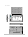
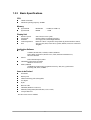
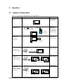
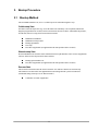
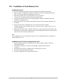
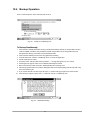
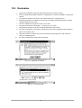
PA-2400W
Software Manual
(Version 1.00)
CASIO Computer Co., Ltd.
Copyright ©1999. All rights reserved.
July 1999
Table of Contents
Chapter 1
1.1
1.2
1.3
1.3.1
1.3.2
1.3.3
1.3.4
Chapter 2
2.1
Chapter 3
3.1
3.2
3.3
Chapter 4
4.1
4.2
4.3
4.4
Chapter
Chapter
Chapter
Chapter
Chapter
Chapter
4.5
4.6
4.7
4.8
5
6
6.1
6.2
7
8
9
9.1
9.2
10
10.1
10.2
10.3
10.4
10.5
10.6
Overview
Features
External View
Specifications
Hardware
System
Basic Specifications
CPU
Memory
Display Unit
Application Software
Items to be Packed
Option
Operation
System Configuration
Bootup Procedure
Bootup Method
Cold-bootup Start
Warm-bootup Start
Resume Start
Startup with Special Key Sequence
Messages at Bootup
Power Control
Power-ON Factors
Power-ON Disable Factors
Power-OFF Factors
Power Saving Process
Auto Power OFF (APO)
Auto Backlight OFF (ABO)
Low Battery Level Monitoring
Low Battery Voltage Alarm Indication
Remaining Battery Voltage Indication
Recharging and Power Supply
List of Software Products Available
Input Method
Startup of SIP
Software Input Panel (SIP)
Fonts
Registry
Application Development Environment
Overview
Software Development Procedure
Card Backup Tool
Overview
Configuration of Files
Installation of Card Backup Tool
Backup Operation
Restoration
Error
2
4
4
6
7
7
7
9
9
9
9
9
9
10
11
11
13
13
13
13
13
15
16
16
16
16
16
17
17
17
18
19
20
20
21
22
22
22
23
24
25
25
25
27
27
27
28
29
34
36
Chapter 11
11.1
11.2
11.3
Chapter 12
12.1
Chapter 13
Automatic Setup Function
Overview
Specifications
Notes
Display Drivers
Installation of the Display Drivers
Restrictions with PA-2400W
3
37
37
37
38
39
39
40
1. Overview
This manual gives specifications and descriptions of software products pre-installed in the H/PC
(CASSIOPEIA PA-2400W series).
The PA-2400W series runs the Windows CE version 2.11 as its operating system. It employs a new PCB
(printed circuit-board) inside to improve a few hardware specifications. However, the rest of hardware
specifications are remained compatible fully with that of PA-2400U series.
A note to application software developers is, the Windows CE ver. 2.11 was developed to enhance the
total functionality and software application compatibility has been maintained. However, Microsoft does not
guarantees the compatibility of any application software between the ver. 2.11 and ver. 2.00. Therefore,
it is strongly recommended that all operations and functions of application software for ver. 2.00 should be
thoroughly checked by having it run the new ver. 2.11 before use. If the software application does not run
properly on the ver. 2.11, you must modify or adjust it.
1.1 Features
This H/PC has the open-platform OS of Windows CE H/PC Professional Edition Version 3.01 (by Microsoft
Corporation) pre-installed.
Table 1.1 Comparison on the software products between PA-2400W and PA-2400U
Item
PA-2400W (H/PC Pro)
PA-2400U
OS environment
Version 2.11
Version 2.00
Driver
NETWORK (pre-installed in ROM)
NETWORK (shall be installed in RAM
upon use.)
Application software Pocket IE Ver. 3.01
Enhanced Pocket Word, Excel, IE, etc.
by Microsoft
HTML3.2 support
Pocket PowerPoint
Pocket OutLook Ver. 3.01
Inbox with file attachment capability
IMAP4 support
Enhanced Pocket Office (Zoom
Pocket Word Ver. 3.01
capability, etc., added)
Pocket Excel Ver. 3.01
Enhanced Pocket Outlook (Ink
Pocket PowerPoint Ver. 3.01
capability, etc., added)
Pocket Access Ver. 3.01
MS Voice Recorder
InkWriter
Command Prompt
Application software Software Keyboard by CASIO
Software Keyboard by ART
by CASIO and
Sound Vega deleted
Software Keyboard by CASIO
third parties
QuickNote deleted
QuickTrainer embedded
smARTCommander deleted
QuickNote embedded
smARTContact deleted
smARTCommander embedded
smARTMemo deleted
smARTContact embedded
smARTMemo embedded
smARTWriter embedded
Application
Visual C++ Ver6.0,
Visual C++ Ver5.0, Visual Basic
development
Visual Basic Ver6.0 and Tool Kit
Ver5.0, or Visual J++ Ver1.1 and
environment
HandheldPC Professional3.0SDK
Tool Kit
4
In addition to the application software embedded as standard above, this PA-2400W supports specific
applications and functions described in the table below for business use.
Table 1.2
Item
MFC, VB runtime
Software
Automatic Setup Function
Data backup and
restoration with compact
flash card
FLCE, FCHKE in ROM
Support libraries
Display drivers
Alarm startup prohibition
Change of startup picture
Operability
Description
Runtime modules for MFC and PVB are in ROM.
This function can install application software in storage card of PA-2400W upon
reset or card insertion.
Data backup and restoration can be performed by this utility software.
Data exchange between PA-2400W and PC can be performed easily.
Various libraries are available.
- Backlight control
- Power off by software control
- Reset by software
- APO prohibition, etc.
Display drivers are supported for Landscape-orientation and portrait-orientation.
Function to start up PA-2400W by alarm can be disabled. (by a library)
Picture at a time of reset is changed.
To avoid turning on the power by merely touching the power switch, the makeon duration of the power key is extended (for 300 msec.)
Note:
Applications and functions in the table above are changed or modified without a prior note to distributors and
end-users.
5
1.2
External View
Fig. 1.1 External View
ADP
LIGHT
CASSIOPEIA
A
CONTRAST
RS-232C
IrDA
NOTI
CHG SYS
CF CARD
ROM
BOARD
BACK UP
BATTERY
LOCK
FREE
MAIN BATTERY
6
POWER
1.3 Specifications
1.3.1 Hardware
Size
Weight
Battery
Operating hours
179 mm (W) x 107 mm (D) x 21 mm (H)
Approx. 370 g
Lithium-ion battery pack (main battery)
Alkaline batteries (LR6 x 2) can also be used as substitution.
CR2032 x 1 + IVR2430 x 1 (sub-battery)
Lithium-ion battery pack
Approx. 10 hours (adequate for 90 Pocket Word strokes/minute) or
Approx. 15 hours in “10:1” mode
Alkaline batteries LR6 x 2
Approx. 10 hours (adequate for 90 Pocket Word strokes/minute) or
Approx. 25 hours in “10:1 “ mode
1.3.2 System
OS
PC Card
CF Card
Connection with PC
Connection with conventional products
Infrared communication
: Windows CE Ver. 2.11
: Conforms to PC Card Standard, Type II slot x 1
: Compact Flash Card Slot x 1
: RS-232C I/F, 16-pin connector, Max. 115.2 Kbps
: 3-pin connector, Max. 38.4 Kbps
: Conforms to IrDA 1.0, Max. 115.2 Kbps
7
Fig. 1.3 System Configuration
#
$ !!&+78
1- %
-9#%
$ !!&+78
$% ./
0/
/
$ # & ) $* !"" &)+ '"
(% ) . 2
/
#,
1
!"" !"" #
3 ,
- /*
45 3 ,6
$ !!&+78
8
1.3.3 Basic Specifications
CPU
Hitachi 32-bit RISC
Maximum operating frequency: 80 MHz
Memory
System ROM
System RAM
: Mask ROM
: DRAM
: 16 MB (OS: 8 MB x 2)
: 8 MB
Display Unit
Number of pixels
Touch panel
Gradation
Contrast adjustment
Font
: 480 x 240 (0.275 mm / pitch)
: Analog resistance membrane (non-glare)
: 4-level grayscale (with backlight function)
: Hardware control + temperature compensation (by built-in hardware control)
: True type font (Arial, Courier New, Symbol, Tahoma, Times new roman and
Wingdin)
Application Software
PIM
Internet
Calculator, World Clock, Calendar, Contacts, InkWriter
Pocket Word, Pocket Excel, Pocket Access, Tasks, Pocket PowerPointViewer,
MS Voice Recorder
Pocket Internet Explorer, Inbox
CD-ROM (by Microsoft Corporation)
Windows CE Servies 2.2
Others (in ROM)
smARTWriter (hand-writing recognition software by ART, Inc.), Quick Trainer
IO Startup, SIP, FLCE, FCHKE
Items to be Packed
PA-2400W
Dummy card
Lithium-ion battery pack (rechargeable)
AC adaptor
Stylus
RS-232C cable
CD-ROM (Windows CE Service)
Manuals (Getting Started, Read this first!, User’s Guide)
Compact flash card
The above items come as standard.
9
1.3.4 Option
Recommended options for PA-2400W can be found on the Microsoft Web pages for locally available options
or by information available from CASIO for PA-2400W’s dedicated options.
The user assumes all responsibility for the use of options recommended neither by CASIO nor by Microsoft.
10
2. Operation
2.1 System Configuration
Table 2.1 Typical system configurations for various applications
Operation Mode
With PA-2400W
only
With PA-2400W
and Modem card
System Configuration
Use of System
Business application,
Input of document,
Data calculation
Cellar phone,
Mail reception
Mail transmission
WEB browse
Data transmission
Program transmission
FAX transmission
public phone
Data storage
Data transmission
Program transmission
With PA-2400W,
SRAM card,
ATA card
and CF card
SRAM card
ATA card
CF card
With PA-2400W and
PC
(connection via
RS-232C interface)
Data transmission
Program transmission
16-PIN
9-PIN
Data transmission
Program transmission
PA-2400Ws and
I/O Boxes
(Satellite I/O boxes in
chained connection)
RS-232C
Max 8 units
Data transmission
Program transmission
With PA-2400Ws
and I/O Boxes
(Master and Satellite
I/O Boxes in chained
connection)
SCSI
11
Operation Mode
With PA-2400Ws
via
IrDA interface
System Configuration
Use of System
Program transmission
Data transmission
Report print
With PA-2400W
and
Handheld printer
With PA-2400W
and
Bar Code reader
Barcode input for
product control
With PA-2400W
and LAN card,
RF-LAN card
Network
Connection
Intranet terminal
Data transmission
Mail client
LAN
12
3. Bootup Procedure
3.1 Bootup Method
The PA-2400W (Windows CE, Ver 2.11) will boot up in one of the following three ways:
Cold-bootup Start
If no data is stored in Object Store (e.g. in case the main or the sub-battery is to be replaced) and after the
diagnosis program has been executed, a Power-ON start from "Power-On factor" will initialize Object Store,
boot the OS, make user setups, and execute Welcome Wizard.
Initialization of hardware
Initialization of Object Store
Booting up Windows
User setup
Execution of application (An application in the start-up folder will be executed.)
Warm-bootup Start
Press the RESET SW to cancel the resume function, then boot up the Windows CE to execute an application
software. In this case the Objective Store data is retained.
Booting up the Windows CE
Execution of application (An application in the start-up folder will be executed.)
Resume Start
This is a Power-ON start because the "Power-On factor" was used once after the OS was booted up.
This continues execution of the same application that was running when the system was turned off.
(The default setting of start-up is set to “Resume mode”.)
Continuous execution of application
13
Battery is installed.
File area is cleared.
Cold-bootup
(Battery is not installed)
Work area is cleared.
Warm-bootup
(Reset SW)
Device is ready for
startup.
Fig. 3.1 Bootup Process
3.2 Bootup with Special Key Sequence
To aid maintenance or application development the following functions can be initiated depending on
simultaneous key and switch operation. In case the bootup is done by this method, the RESET SW should be
pressed last.
Table 3.1 Types of Bootup
Function
Notification SW
Cold bootup
O
Diagnosis program
Memory dump
Warm bootup
O
-
LIGHT
-
RESET SW
O
POWER
-
O
O
-
O
O
O
-
Remark
With confirmation
message
Results from the diagnosis program or memory dump operation described above are outputted via the 3-pin
interface. Therefore, these results can be examined on a PC which is connected via the interface of PA-2400W.
Notes;
1. Diagnostic Program
The diagnostic program will write data and read it in the RAM. If you press the special key above, the
diagnostic procedure starts, and the Indicator LED will turn on in red if a result is OK otherwise it flashes.
2. Monitoring on PC
Output from the PA-2400W can be monitored on PC side. Connect the PA-2400W with a 3-pin RS-232C
cable to PC and set up the parameters of terminal software at PC as follows.
Baud rate
Data length
Parity bit
Stop bit
: 38400 bps
: 8 bits
: none
:1
14
3.3 Messages at Bootup
Messages below will be displayed when a FULL RESET (with NotificationSW + Reset) is performed or if the
status of memory is illegal. One of the messages is displayed to notify the user unstable system condition by
illegal process in application program.
Fig. 3.2 Message at full reset
Fig. 3.3 Message at unstable memory status
Fig. 3.4 Message at detection of unstable condition
15
4. Power Control
4.1 Power-ON Factors
Power-on factors include:
The power is turned on by pressing the POWER SW.
The power is automatically turned on at the specified time by the alarm function.
The power is automatically turned on if the CD signal is detected by the PA-2400W connected
to PC via the RS-232C cable.
The power is automatically turned on when the PA-2400W is mounted on I/O Box.
If the power is supplied from the I/O Box, the detection on which the PA-2400W is being mounted
on I/O Box can turn on the power. The APO and POWER SW functions are operable while the
PA-2400W is supplied with power from the I/O Box.
The power is turned on by pressing the Notification button.
4.2 Power-ON Disable Factors
The following conditions are checked before the power is turned on. If any of the following conditions exist, the
power is not turned on.
If the main battery voltage is too low for the PA-2400W to be booted up.
If the battery lock is not secured.
If the compact flash card cover is off.
4.3 Power-OFF Factors
Power-off factors include:
The power is turned off by pressing the POWER SW if the power is on.
The power is automatically turned off, as specified in program setup, if any operation (key operation,
touch panel operation, disk operation, card access, or communication) is not performed in a given period
of time. This is called the APO function.
The power is automatically turned off if the main battery voltage is below the specified level.
The power is turned off if the battery cover lock is released.
The power is turned off if the compact flash card lock is released.
16
4.4 Power Saving Process
Auto Power OFF (APO)
Automatically turns off the system if any action (key operation, touch panel operation, disk access operation,
card access, or communication) is not performed in a given period of time. The software can set whether the
APO function is enabled or disabled and the APO time. The APO time can be set to between 1 and 5 minutes,
in 1 minute increments.
Fig. 4.1 APO setup screen
Auto Backlight OFF (ABO)
Automatically turns off the backlight if any action (key operation or touch panel operation) is not performed in a
given period of time. The corresponding utility can be used to set whether the ABO function is enabled or
disabled and the ABO time setup. The backlight will also be turned off if a VDET1 event occurs.
Fig. 4.2 ABO setup screen
Note: The backlight will be automatically turned off if a VDET1 event occurs while the backlight is turned on.
17
4.5 Low Battery Level Monitoring
For the PA-2400W there are three low battery levels available which can be used to detect low battery voltage.
Table 4.1 Battery voltage monitoring levels
Level
Contents
VDET1
Low main battery voltage alarm
VDET2
Power off due to low main
battery voltage
Power off immediately due to
low main battery voltage.
Low sub-battery voltage alarm
VDET3
VDETS
Operation
Next boot-up
Indicates low main battery
voltage alarm
Turns off the power.
--Resume
Critical off.
Warm-bootup
Indicates low sub-battery voltage alarm.
Fig. 4.3 Voltage monitoring levels
Voltage
Voltage
Voltage
Condition
Good
Low
VDET1
Danger
VDET2
Dead or
No battery
ACL
Main battery
VDETS
VDET3
Regulated voltage
18
Sub-battery
4.6 Low Battery Voltage Alarm Indication
The following alarm screen appears if the main battery or sub-battery voltage drops.
Fig. 4.4 Low main battery voltage alarm screen
Fig. 4.5 Low sub-battery voltage alarm screen
19
4.7 Remaining Battery Voltage Indication
The remaining battery voltage can be displayed if the Power Management icon or Battery icon is touched on the
Control Panel.
Fig. 4.6 Battery property display screen
Note:
The "LOW" indication also appears if a VDET1 event occurs, even if it occurs when the backlight is on. If the
voltage is "Low" or "Very Low" the backlight can not be restored to ON. If the battery condition is reset by
turning the power on and off, the "LOW" indication will be canceled.
4.8 Recharging and Power Supply
The main battery (lithium-ion battery pack) can be recharged in three ways as follows:
Replace with a fully charged lithium-ion battery pack. Remove the battery pack and charge it using the
battery charger (PA-2040DCHG-E).
Set the battery pack in the PA-2400W, then mount the PA-2400W on the I/O Box to charge the battery
pack..
Retain the battery pack in place of the PA-2400W, then connect the AC adaptor (AD-C50200U-S for
AC input 120V or AD-C50200G-S for AC input 230V) to the PA-2400W.
Data security at battery replacement is described below.
As long as either the main battery or sub-battery is installed, the data in Object Store is retained.
Table 4.2 Data security depending on battery presence
Installed battery
Data in Object Store
Main and sub-batteries
Retained
Only main battery
Retained
Only sub-battery
Retained
No battery
Can not be retained
20
5. List of Software Products Available
Table 5.1
Category
OS
Pre-installed
Application
Program
Software Product
Windows CE
Pocket Word
Pocket Excel
Pocket Explorer
Pocket IE
Pocket PowerPoint
Pocket Access
MS Voice Recorder
InkWriter
PIM
Calculator
World Clock
Calendar
Contacts
Tasks
InternetMail
Terminal
Command
Utility
FLCE
FCHKCE
Automatic setup
SIP
smARTwriter
DLL
IO Box Startup
Library
Support Library
Host
LMWIN
Utility
LMDOS
Windows CE Service
PIM : Personal Information Management
Stored
Location
ROM
ROM
ROM
ROM
ROM
ROM
ROM
ROM
ROM
ROM
ROM
ROM
ROM
ROM
ROM
ROM
ROM
ROM
ROM
ROM
ROM
ROM
ROM
RAM
PC
PC
PC
21
Remark
OS Version 2.11
Pocket word
Pocket excel
Pocket explorer
Pocket Internet Explorer
Pocket power point
Pocket access
MS voice recorder
Ink writer
Calculator
World-time clock
Calendar
Address book
Scheduler
Internet mail
Terminal client software
Command prompt
File transfer (via I/O Box, between PA-2400Ws)
Transferred file checks
Automatic application installer
Software Keyboard
Handwriting recognition
Detection of mounting PA-2400W on I/O Box
Libraries for developing application
Communication program resided in PC (WIN95)
Communication program resided in PC (DOS)
PA-2400W-to-PC link software (NT4.0, WIN95)
6. Input Method
6.1 Startup of SIP
By pressing the SIP key, the software keyboard can appear and disappear. The SIP key toggles ON and OFF
the software keyboard.
Table 6.1
Key
Function Description
SIP
Starts up and displays the software keyboard.
LIGHT
Turns ON and OFF the backlight.
SIP + LIGHT
Starts up the calibration mode.
SIP : Software Input Panel
6.2 Software Input Panel (SIP)
This software input panel can be initiated if the icon in the task bar is touched. It can change its state in three
different modes.
Alphanumeric input pad
Fig. 6.1 Alphanumeric input pad (with Shift key not pressed)
Fig. 6.2 Alphanumeric input pad (with Shift key pressed)
Fig. 6.3 Alphanumeric input pad (with Number key pressed)
22
7. Fonts
Only true type fonts can be used.
It is possible to add more font types to the pre-installed fonts. To do this, use Mobile Devices to download the
font from the Windows Fonts directory on the PC to the PA-2400W. This operation converts the original font
via the font filter to a format that can be used on the PA-2400W. After download, switch to the desired font on
the PA-2400W.
Table 7.1 Fonts
Item
FONT type
Pre-installed true type fonts
Size
Contents
True type font
Arial
Courier New
Symbol
Tahoma
Times New Roman
Wingdings
8 to 36 points
23
Remark
Selectable
8. Registry
The following list shows the registry values that have special meanings on the PA-2400W.
Default Setting of SIP keyboard
[HKEY_LOCAL_MACHINE\Software\Apps\SIPManager]
SIPExeName"="SIPanel.exe"
SIPQuitOpt"="/q"
Table 8.1
“SIPExeName
"SIPNormOpt"
“SIPQuitOpt"
Description
Name of a program that is started up when the SIP button is
depressed.
The user must change this default name to his own program
name for his own SIP keyboard.
If the SIP keyboard is to be disabled, just delete the program
name.
This must be set up if there is any option available for starting
up the program.
This must be set up if there is any option available for closing
the program.
24
9. Application Development Environment
9.1 Overview
User applications may be developed under the following development environment.
Table 9.1 Application development environment
Development platform
Microsoft Windows NT4.0 +SP3 or later (English version)
Development language
Microsoft Visual C++ Ver6.0 + ToolKit for Visual C++ 6.0
Microsoft Visual Basic Ver6.0 + ToolKit for VisualBasic 6.0
HandheldPC Professional 3.0SDK
Note:
For a latest software development environment, always check on published information by Microsoft by
clicking the URLs.
http://www.microsoft.com/windowsce/
http://www.msdn.microsoft.com/cetools/
For Java’s software development environment, there has been no development environment available.
9.2 Software Development Procedure
Application program developers should follow the three steps shown below to develop and debug user
programs.
Emulation on PC
Construct the user codes in the X86emu so that operation of the user program can be checked under the
emulated Windows NT4.0 environment. Within this emulated environment most of the debugging tasks can
be performed.
Remote debugging
Transfer the finished application program into an actual PA-2400W and debug it from the remote terminal.
Operation check on actual PA-2400W
Check the operation of the finished application program by installing it, through the MSDEV integral
environment or Mobile Devices, on actual PA-2400W and execute the program.
25
Flow-chart of Development Procedure
Edit source code
Edit resource.
Compile/link X86 Debug
Debug emulation
Compile/link SH Debug
Transfer debug module
Remote tool/
Remote debug
Execute debug
Compile/link SH Release
Transfer release module
Execute
PC side
PA-2400W side
Fig. 9.1 Software development procedure
For more information refer to the Microsoft ToolKit and other reference manuals published separately for
Windows CE.
26
10. Card Backup Tool
10.1 Overview
This “Card Backup Tool” can back up object store area in RAM memory of the PA-2400W and user’s data to a
compact flash card and can restore them. The following items can be backed up with this tool.
File
Registry
CE data base (Reception tray, task, data of the address notebook)
The methods to back up these data are “Manual Backup” and “Automatic Backup” which can be performed at
a specified time.
Notes:
1. Password once you set up at the control panel cannot be backed up and restored by this tool. When you
restore the backed up data, the protection by password can be no longer valid if you switch on the power.
2. Restoration of the backed up data cannot be possible if the desk-top icon is deleted or the file is deleted by
a FULL RESET.
10.2 Configuration of Files
Depending on installation method you use to install the tool, there are two different configurations of the files.
Installation from PC
PCSetup.exe
CASIOBU.CAB
Readme.txt
Setup.ini
Installer to install the tool to the PA-2400W and a compact flash card installed in
the PA-2400W.
Compressed file
Read-me text
Installation from PC card (or compact flash card)
Setup.exe
CFbkup.exe
CardBackupBoot.lnk
Cardbackup.lnk
CFbkups.htm
Cfbkup.htm
Pwrhdl.dll
Readme.txt
Installer to install the tool to the PA-2400W.
Backup utility
Short cut
Short cut
Help file
Help file
27
10.3 Installation of Card Backup Tool
Installation from PC
1. First, close all application programs run on the PA-2400W before starting the setup program.
2. Install a PC card (or a compact flash card) into the PCMCIA card slot (or the compact flash card slot)
where you wish to download the “Card Backup Tool” from PC.
3. Connect the PA-2400W to PC using cable while the power is switched on.
It may take time to establish session between the PA-2400W and PC.
4. To start the setup, click twice on the icon of “PCSETUP.EXE” of FDD or CD-ROM (see note) that
contains the “Card Backup Tool”.
5. Specify a folder for PC to copy module of the application in the PC before coping the application to the
PA-2400W.
6. All necessary files for the “Card Backup Tool” to run will be copied to the PA-2400W.
If dialogue message “File xxxx already exists. Do you wish to overwrite ?” appears, select on “Yes” or
“To overwrite all files“.
7. Installation files are copied to the “\CASIOBU” folder of PC card (or compact flash card) to install “Card
Backup Tool” to the PA-2400W. If both the cards are being installed at the same time, a storage card will
be the card to be selected as copy destination file.
Note:
The “Card Backup Tool” is also available in the CASIO’s Service CD-ROM which can be obtainable from
CASIO TECHNO Co., Ltd..
Installation from PC card (or compact flash card)
1. Insert the card that contains the “Card Backup Tool” into the PA-2400W’s PCMCIA card slot (or
compact flash card slot).
2. Use Explorer to navigate to the “\Storage card\CASIOBU”, and double tap the setup icon
(“setup.exe”).
3. The setup program copies the “Card Backup Tool” and install it on your system.
4. After setup, reset the PA-2400W before using it.
5. To run the “Card Backup Tool”, select it in the Start menu.
28
10.4 Backup Operation
Select “Card backup Tool” in the start menu and execute it.
Fig. 10.1 Startup of Card Backup Tool
To Backup Data Manually
1. Turn off the PA-2400W and install a memory card into the PCMCIA card slot (or compact flash card slot)
of the PA-2400W. If both the cards, PCMCIA card and compact flash card, are being loaded, the card
that specified as Storage Card will be used for destination folder.
2. Turn on the PA-2400W power and close any applications if running.
3. From the Start menu, select the “Card Backup Tool” to execute the application.
4. Tap the “Backup now” button.
5. In response to the “This procedure backs up all data …” message that appears, tap “Yes” button.
6. An hourglass icon appears on the screen to indicate that backup has started.
7. Data to be backed up will be stored into “\Backup\backup.dat” of Storage Card.
8. The backup operation takes a few minuets. During that time do not input anything from the keyboard or tap
the screen with the stylus.
9. If you wish to abort the execution, tap on the close (“x”) button in the upper right corner of the window.
10. After backup is complete, tap the close (“x”) button to close the “Card Backup Tool”.
Fig. 10.2 Manual data backup
29
Fig. 10.3 While executing
Fig. 10.4 While aborting
Fig. 10.5 End of manual data backup
30
Fig. 10.6 Error message
Fig. 10.7 Error message (when the battery is low)
31
To Schedule Auto Backup
1.
2.
3.
4.
5.
From the Start menu, select “Card Backup Tool” to execute the application.
Input the time when you want Auto backup to be performed.
Check the “Auto backup” checkbox.
Tap the “Change auto backup settings” button.
After you are finished with making the settings you want, click the close button in the upper right corner of
the window to close the “Card Backup Tool”.
6. The backup operation will be performed at the time you specified, regardless of whether the PA-2400W is
on or off. Be sure that you have a memory card loaded in the PA-2400W if it will be turned off before the
backup time arrives. Also, make sure that no other applications are running at the time for which backup is
scheduled. If both the cards, PCMCIA card and compact flash card, are being loaded, the card that specified
as Storage Card will be used for destination folder. The backup operation takes place at specified time and
copies necessary files to the folder in Storage Card, \backup\backup.dat.
7. When the backup operation is complete, the PA-2400W will indicate time that the backup operation has
been complete and turn off the power. A next backup operation will become possible if the user ends the
backup operation. Otherwise, it will not be possible.
8. If one of the followings occurs when the backup operation starts, the backup operation will be automatically
postponed.
While the power is being turned on (during the process of power-on). The backup operation will be
postponed for one day.
The remained battery capacity is low (the backup operation will be postponed until a next operation is
performed.)
A card is not being loaded in one of the slots (the backup operation will be postponed until a next
operation is performed.)
A card loaded is with write-protection set or cannot be accessed.
A card loaded has not enough free memory capacity to store data.
Fig. 10.8 End of automatic data backup
32
Fig. 10.9 Error message (while end-user is operating)
Fig. 10.10 Error message (not enough memory or a PC card is not loaded)
Fig. 10.11 Error message (when the battery is low)
33
10.5 Restoration
1.
2.
3.
4.
5.
6.
7.
8.
9.
10.
Perform a FULL RESET operation to delete all data from the PA-2400W’s memory.
Insert the compact flash card that contains the “Card Backup Tool” into the PA-2400W’s compact flash
card slot.
Use Explorer to navigate to the memory card, and then start up the “Card Backup Tool”.
If the backed up data is on a different card, remove the card with the application and replace it with the
card that contains the back up data.
On the PA-2400W screen, tap on the “Restore now” button.
In response to the “Before restoring data …” message, tap “Yes” button.
An hourglass icon appears on the screen to indicate that data restore has started.
The restore operation takes a few minutes. During that time do not input anything from the keyboard or
tap the screen with the stylus.
After data restoration is complete, tap on the close button in the upper right corner of the window to
close the “Card Backup Tool”.
Reset the PA-2400W before using it after restoring data.
Fig. 10.12 Beginning of restoration
Fig. 10.13 End of restoration
34
Fig. 10.14 Error message (PC card is not loaded or no data to back up)
Fig. 10.15 Error message (when the battery is low)
35
10.6 Error
An error message will appear if the followings occur in each performance of the manual backup, automatic
backup and restoration. After appearance of the error message, solve the error and execute the performance
again.
Battery capacity is low.
PC card (or compact flash card) is not loaded in the slot.
PC card (or compact flash card) has not enough free memory capacity.
No backup data existed (in the restoration performance).
For error messages that appear refer to Chapter 10.4 “Backup Operation”.
36
11. Automatic Setup Function
11.1 Overview
In this chapter, method to install an application program by using the “Automatic Setup Function” is described.
Often an application program is pre-installed by you before shipment to end-user. The application program once
installed in the PA-2400W could be deleted accidentally by operator or because of the excess duration of battery
life. If such the case happens, you need to re-install the same application program into the PA-2400W at
end-user’s business site and right away. The “Automatic Setup Function” can automatically install application
program being resided in compact flash card (or PCMCIA card) into the PA-2400W at time of a reset or power
on.
11.2 Specifications
When the PA-2400W is reset or the power is turned on right after compact flash card (or PCMCIA card) is
installed, “Setup.exe” or “AutoRun.exe” which is resided in the card is automatically executed.
Directory: \Storage Card\CE\SH3
(If both a compact flash card and a PC card are installed, “Storage Card2” is searched, too.)
The card driver searches setup file registered in registry of the card for about 30 seconds after a reset.
When the following file is found with the card driver, the “Automatic Setup Function” is executed.
[HKEY_LOCAL_MACHINE\Drivers\CASIO\UTIL\SETUP]
“1”= “\\Storage Card\\CE\\SH3\\Setup.exe”
“2”= “\\Storage Card2\\CE\\SH3\\Setup.exe”
Or, “AutoRun.exe” is searched for about 30 seconds after a compact flash card (or PCMCIA card) is
installed into the PA-2400W. When the following file is found, the “Automatic Setup Function” is
executed.
[HKEY_LOCAL_MACHINE\Drivers\CASIO\UTIL\AUTORUN]
“1”= “\\Storage Card\\CE\\SH3\\AutoRun.exe”
“2”= “\\Storage Card2\\CE\\SH3\\AutoRun.exe”
This “Automatic Setup Function” can be disable by deleting the keys.
Setup Program/Automatic Execution Program
Since the “Automatic Setup Function” will automatically start up “Setup.exe” every time a reset is
performed, avoid setting up “Setup.exe” twice. Avoid also setting up the “AutoRun.exe” every time when
a card is installed.
If both “Setup.exe” and “AutoRun.exe” are found at same time after a reset is performed, the former has
priority.
If both cards (compact flash and PC cards) are installed in respective slot and the setup program and the
automatic execution program are resided in each card, the priority is as follows.
When reset is performed
When card is installed
: Storage Card
: Storage Card2
37
11.3 Notes
If both compact flash card and PC card are being loaded in the PA-2400W and a reset is performed, a
compact flash card installed in the compact flash card slot will become “\\Storage Card”.
Suppose both “Storage Card” and “\\Storage Card2” are existed in the slots, and pull out the “Storage
Card” and re-install it immediately, the “Storage Card2” can still be accessed.
Setup program and automatic setup program are searched for 30 seconds after Welcome wizard has been
started up by a cold-bootup.
If you install a PC card into one of the slots, a dialogue message appears. Click “YES” button within 30
seconds.
38
12. Display Drivers
Display drivers available from CASIO can consist of two different orientations, either Landscape or Portrait,
versions of 90-degree, 180-degree and 270-degree. These display drivers are used to re-position the LCD screen
of the PA-2400W at a tilted angle for such use as that for example the IrDA port to be located at the opposite
direction (to right side). The drivers are provided in the development kit and can be found as following names.
Table 12.1
File name of drivers
DDI_90.DLL
DDI_180.DLL
DDI_270.DLL
Orientation in degree
90
180
270
12.1 Installation of the Display Drivers
Follow the installation steps bellow when you install one of the display drivers into the PA-2400W.
Installation
1. Rename the desired DDI_*.DLL file to DDI.DLL.
2. Download the "DDI.DLL" file to Windows directory in the PA-2400W by using communication software of
“Windows CE Services” or download it from a PC card.
3. When the installation is complete, press the RESET switch at the back of PA-2400W and start up it again.
4. As soon as the power is turned on and the display is resumed on the LCD display, be sure to perform the
calibration on the LCD touch panel.
The calibration mode can be started up by pressing down the <SIP> and <Backlight> buttons at the same
time. Once you are in the mode, tap “+” marking on each corner on the LCD touch panel with the stylus.
If you install this display driver once, it will stay active in the memory of the PA-2400W until a FULL
RESET will have been performed.
Restrictions
PA-2400W cannot display the software keyboard because the width of the keyboard is physically wider
than the height of the LCD screen of the PA-2400W when the LCD screen is tilted at 90 degrees (when
the 90-degree or 270-degree version is installed).
When you set the task bar to appear always on the LCD screen (when the 90-degree or 270-degree version
is installed), a warning message will appear.
Operations with the PIM software cannot be possible because it is for the Landscape-orientation display. If
you install the 90-degree or 270-degree version, your application software must be also changed for the
Portrait-orientation display.
39
13. Restrictions with PA-2400W
The followings are restriction and limitation that user of the PA-2400W may encounter while operating. The
user must always be aware of them. Countermeasure against each restriction is also described for your
reference.
Compatibility of application software under Windows CE ver. 2.00 and ver. 2.11
Neither Microsoft nor CASIO assure you compatibility of application software. In other words, an
application software which can perfectly run the Windows CE version 2.00 may not necessarily run the
version 2.11, and vice versa.
Abrupt reset
While operating the PA-2400W, an abrupt reset may occur once in a while which can cause data and
program to be erased. All data and program are recommended to back up periodically to compact flash
card or PC card.
Locking during warm-bootup
While the PA-2400W is warm-booted up, the system may lock once in a while. Just push the RESET
switch at the back to unlock the condition if occurred.
Irregular IrDA communication
Because of IrDA specifications of a target device, communication via IrDA interface between the PA2400W and the target device cannot be possible. In such case, it is often caused by deviated specifications
of IrDA interface of the device from that of the PA-2400W. Make sure first all the IrDA specifications
of the PA-2400W and the device.
Life of battery
Temperature and humidity surrounding the PA-2400W can affect the duration of battery life. If
temperature and humidity are high, the life of battery becomes shorter than that of originally specified
duration and consequently it causes the low battery warning message to appear earlier. When such the
message appears, stop operation and recharge the battery immediately. Also, the AC adaptor (model; ADC50200-S) to power the PA-2400W is recommended for any operation with device(s) being connected
that consume heavy amount of current.
PCMCIA card
The limited amount of current that can be consumed by PCMCIA card is 300 mA or less. Any PCMCIA
card with requirement of 300 mA or over as its power to operate must not be used with the PA-2400W.
The low battery warning message appears in early stage or the PA-2400W itself locks abruptly if such a
card is installed. CASIO recommends you to use one of the PCMCIA cards listed on page 7 in the PA2400W Hardware Manual.
40