1
7. BT. Connections
2. Installation Requirements
1.
Remove the centre PCB screw and remove the plastic cover over the telephone
connection terminals.
2.
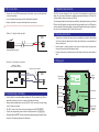
Connect telephone line using one of the methods shown below:
The SD1+ has been designed to be connected to an intruder alarm control panel or
similar. The control panel must have an auxiliary power output of between 11.5V and 14V,
and the ability to provide a minimum of 100mA.
3.
Replace the plastic cover over the telephone line connections.
+
The unit is supplied with a 2 metre telephone lead which will plug directly into any standard
BT socket and it is therefore recommended that the unit is sited as near to a BT telephone
socket as possible. If this it not possible an approved BT extension lead may be required or
the unit can be hard wired to the BT. socket (see section 8).
Failure to refit the plastic cover will contravene mandatory European standards
Method 1 - Using the lead supplied
3. Mounting Instructions
SD1+
White
Red
A
B
Standard BT telephone plug
1.
Separate the cover from the base by using a screwdriver to push two of the retaining
clips (top or bottom) inwards from the base indents. Remove cover assembly and
store in a safe place.
2.
Hold the base in position (keyhole to the top) and mark the three securing holes.
Remove the base then drill and plug the holes.
3.
Pass all cables into the base through the cable entries and then secure the base to
wall.
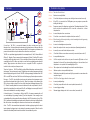
4. PCB Layout
Method 2 - Hard wired connections
BT Master Jack (NTE5)
User accessible connections
Cable type 1/0.5mm CW1308
3
2
1
Blue/White
Trigger Polarity
Jumper-link
A
B
12V Power Input
8. Commissioning and Testing
1.
2.
Hold the blade of a small screwdriver between the “Factory Restart” pins (JP2) and
switch the power back on to the control panel (battery and mains).
Remove the screwdriver blade and clip the SD1+ front cover onto the base taking
care not to trap any cables.
3.
The SD1+ "beeps" every 30 seconds and the display shows: PLEASE RECORD.
4.
To select the programming mode enter the default passcode of [1] [2] [3] [4].
5.
The display will show READY. The unit is now ready for programming and testing. Please
refer to the ”Operating Instructions” for full details.
(SELV)
Output 1
Abort Input
+
Factory Restart
SD1+
TRIG
POLARITY
MENVIER
SD1+
Factory
Restart
Pins
SECURITY
+12v
0v
O/P1
Microphone
ABORT
TRIG A
3 Trigger Inputs
TRIG B
Plastic cover
TRIG C
Box Tamper
TAMP
White/Blue
6
5
4
Tamper switch
A B
TELEPHONE CONNECTIONS
Loudspeaker
Telephone Line
Connection
Terminals
(TNV)