1
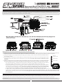
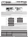
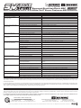
ATX 92803 / 107A41262A
Sensored Brushless Sport ESC
with Integrated RX-472 2.4GHz FH4T Super Response SSL Receiver
The new Super Vortex-Plus Sport takes all the features of a sport-minded ESC and the RX-472 2.4GHz FH4T SSL receiver and integrates them into one
lightweight, compact unit, specifically designed for electric on-road and off-road use. Integrating both the ESC and receiver results in a much lighter
and more efficient setup than using a separate ESC and receiver. It’s the perfect combination for the sport user looking for a competitive edge.
IMPORTANT: This product is not compatible with Airtronics or Sanwa FH2 surface transmitters or aircraft transmitters. SSL function only
available when used with an Airtronics M12, MT-4S or Sanwa EXZES-Z transmitter. Super Response feature only available when used with an
Airtronics or Sanwa FH4T transmitter in SSR Mode with Airtronics or Sanwa Super Response SRG digital servos. Telemetry requires telemetry
capable transmitter (M12, MT-4S, MT-4 or EXZES-Z).
features and specifications
• Frequency: 2.4GHz FH3/FH4T Selectable Via Transmitter
• Supports SSL (Remote Programming via Transmitter)*
• Nominal Input Voltage: 6.0 to 7.4 Volts
• Motor Limit: 8.5T or Greater
• Input Power (Cells): 2S Li-Po (6C Ni-Cd/Ni-MH)
• On Resistance: 0.00090 ohms
• Brushless Sensored Design w/Custom Sanwa Programming
• Rated Current : 370 Amps/Phase @ 25ºC (77ºF)
• Compatible with Normal, SHR and SSR Channel Modes*
• BEC: 6.0V/3.0A
• Adjustable Voltage Cut-Off for Li-Po and Ni-Cd/Ni-MH Batteries
• Dimensions: 1.44 x 1.48 x 1.07” (36.6 x 37.8 x 27.4mm)
• Twelve Programming Modes (Red, Blue & Green ESC Setup LEDs)
• Weight: 66.5g (w/Wires, Switch and Capacitor)
• Thermal Overload Protection Circuit
*When Used With Compatible Airtronics or Sanwa Transmitter.
what’s included
• Super Vortex-Plus Sport ESC w/Integrated Receiver
• User’s Guide
• Motor Sensor Cable
2.4GHz frequency band precautions
• The receiver operates on the 2.4GHz frequency band. The 2.4GHz connection is determined by the transmitter and receiver pair. Unlike
ordinary crystal-based systems, your model can be used without frequency control.
• Due to differences in the implementation of 2.4GHz technology among different manufacturers, the receiver is not compatible with any other
transmitter brands.
• The 2.4GHz frequency band may be used by other devices, or other devices in the immediate area may cause interference on the same
frequency band. Always before use, conduct a bench test to ensure that the servo(s) operate properly. Also, conduct checks with the transmitter
as distant as possible from your model.
• The response speed of the receiver can be affected if used where multiple 2.4GHz transmitters are being used, therefore, carefully check the
area before use. Also, if response seems slow during use, stop your model immediately and discontinue use.
• If the 2.4GHz frequency band is saturated (too many transmitters on at once), as a safety precaution, the transmitter and receiver may not pair.
This ensures that your radio control system does not get hit by interference. Once the frequencies have been cleared, or the saturation level
has dropped, your transmitter and receiver should be able to pair without any problems.
general usage precautions and warnings
• This product is designed for use with Airtronics or Sanwa 2.4GHz FH3 and FH4T radio systems. This product will not function with any other
radio system types or brands. Functionality is limited when used with FH3 radio systems and FH4T radio systems that don’t support SSL.
• If you're using analog servos, DO NOT use SHR or SSR Servo Modes for that channel, otherwise the servos and/or receiver can be damaged.
• The antenna consists of a coaxial cable and a reception wire (the thin tip at the end of the coaxial cable). When you mount the antenna, do
not bend the reception wire. Reception performance decreases if the reception wire is bent. The coaxial cable can be bent into gentle curves,
however, do not bend the coaxial cable acutely, or repeatedly bend it, or the antenna core can be damaged.
• The antenna should be installed into a vertical plastic tube per your model's assembly instructions. The antenna should not come into contact
with any carbon or metal chassis components.
• Do not cut or otherwise alter the length of either the coaxial cable or the antenna reception wire.
• There is a danger of runaway operation if connectors loosen during use. Make sure that all connectors are securely fitted.
• The ESC is designed for use with 8.5T or greater (w/2S Li-Po) sensored brushless motors only.
• If you change the battery connector on the ESC (e.g., to match your battery’s power connector), please observe correct polarity. Plugging your
battery into the ESC with reverse polarity will damage the ESC beyond repair!
• Make sure that the motor wiring matches (A, B and C from the ESC to A, B and C on your motor). Since this is a sensored ESC, these must
match or damage to your motor and/or the ESC can result.
• The power capacitor installed on the ESC is mandatory for proper use. Do not remove the power capacitor.
• Do not use a battery with a nominal voltage greater than 7.4 volts (2S Li-Po or 6C Ni-Cd/Ni-MH).
• If the ESC and/or your battery become hot, disconnect your battery from the ESC immediately and allow the ESC and/or your battery to cool
down before reconnecting.
• Mount the Super Vortex-Plus Sport using double-sided foam tape in a position that allows for adequate airflow. Orientate the ESC so that the
cooling fins are parallel to the airflow. Do not wrap in foam rubber and do not mount inside a receiver box.
• Turn your transmitter ON before turning the ESC ON and turn the ESC OFF before turning your transmitter OFF. Always disconnect your battery
from the ESC when not in use.
• The Super Vortex-Plus Sport is not waterproof. Do not run through water or allow the product to become wet with moisture or it can be damaged.
• Maintain your motor on a regular basis to ensure high performance. Degradation of motor performance can put undue stress on the ESC,
resulting in damage to the ESC.
1
Sensored Brushless Sport ESC
with Integrated RX-472 2.4GHz FH4T Super Response SSL Receiver
overview, connections and mounting
IMPORTANT: A motor cooling fan, lap counter device, LED light set, etc., in addition to a gyro or a servo, can be plugged into the AUX2 channel
port using a standard Y-harness (not included). In the default configuration, the AUX2 channel is controlled by your transmitter’s Auxiliary Lever.
If desired, this can be changed in the transmitter’s KEY ASSIGN menu.
G
Green
R
Red
B
Blue
Making Receiver Connections and Mounting the Super Vortex-Plus Sport ESC:
1) Plug your steering servo into the ST channel port, making sure to observe correct polarity. If you’re using a gyro, such as the Sanwa SGS-01C,
plug the gyro into the AUX2 channel port. Make sure to observe correct polarity - Blue (Signal), Red (Positive) and Black (Negative).
2) Using two suitable sizes of double-sided foam tape (not included), mount the ESC and the ESC On/Off switch to
your model’s chassis.
3) Securely plug one end of the sensor cable into the Sensor Input port on the ESC, then securely plug the other
end of the sensor cable into the Sensor Input port on your motor. The sensor cable must be installed for proper
operation.
4) Slide the antenna wire into an antenna tube (not included) and secure the antenna tube in a vertical position. For
the best reception, the antenna wire should be mounted vertical and extend outside the top of your model.
Antenna
Reception Wire
Coaxial Cable
Antenna Tube
• For maximum efficiency, orientate the ESC so that the cooling fins are parallel to the airflow. Do not wrap the
ESC in foam rubber, mount the ESC in a receiver box, or in any way block airflow to the cooling fins.
• Install the On/Off switch on the chassis of your model in a location that’s convenient to access and that doesn’t
interfere with any moving parts. In addition, it may be necessary to secure the battery and/or motor wires to
your chassis to prevent damage to them. Secure the capacitor to the ESC battery wires or the chassis using
a nylon cable tie (not included) to prevent it from being damaged or from shaking loose during use.
• In some cases, such as when there is limited airflow over the ESC or if your using a higher than normal Timing Advance value, a
cooling fan (not included) can be used help prevent the ESC from going into thermal shutdown. A 25 x 25 x 10mm cooling fan with
M2.6 x 13mm mounting screws can be used. The cooling fan should be orientated so that the direction of airflow blows air onto
the cooling fins.
binding the transmitter and receiver
The binding procedure allows you to bind the transmitter and receiver pair. Once the binding procedure is complete, the setting is remembered
even when the transmitter and receiver are turned OFF. The bind code is unique to each transmitter and receiver pair, so you don't need to worry
about other users' transmitters interfering with your receiver. You are only able to bind one transmitter to the receiver at any one time.
IMPORTANT: Before beginning the binding procedure, make all battery and ESC/receiver connections as described in the previous section.
2
Sensored Brushless Sport ESC
with Integrated RX-472 2.4GHz FH4T Super Response SSL Receiver
binding the transmitter and receiver, continued....
1) Turn the transmitter ON and navigate to the BIND menu, then choose your transmitter's modulation type. If using an M12, MT-4S, EXZES-Z,
MT-4 or other FH4T transmitter, choose FH4T. If using an M11X, MX-3X or other FH3 transmitter, choose FH3.
2) Plug your motor battery into the ESC and verify that the ESC On/Off Switch is turned OFF (no lights on ESC).
3) While holding down the Bind Button on the receiver (use a non-metallic instrument,
such as a toothpick), turn the ESC ON. The Bind LED on the receiver will flash
slowly. Release the Bind Button. The Bind LED on the receiver will continue to
flash slowly.
(2) Turn ON
4) From within the transmitter's BIND menu, scroll to highlight the BIND [ENTER] field, then press the ENTER
key on your transmitter (within ~ 5 seconds of releasing the Bind Button). The [ENTER] command will begin
to flash and the Bind LED on the receiver will flash rapidly, then go out.
5) After the Bind LED on the receiver goes out, press the ENTER key a second time. The Bind LED on the
receiver will illuminate solid blue, indicating that the binding procedure is complete. Press and HOLD the
Back/Cancel key to exit the BIND menu.
B
(1) Press & HOLD
IMPORTANT: The BIND menu may vary depending on your transmitter model. If necessary, refer to your transmitter's User's Guide for more
information about the binding procedure. When the binding procedure is successful, the Bind LED on the receiver will illuminate solid blue. If
the Bind LED on the receiver is flashing rapidly or is not illuminated at all, the transmitter and receiver are not paired. In this case, turn both the
transmitter and the ESC OFF, then repeat the binding procedure again.
Bind LED Condition Indicator:
The Bind LED can be used to determine receiver condition at a glance. The Bind LED will alert you to various receiver conditions, as described below:
Condition
Bind LED
receiver servo mode setting
Receiving RF Signal
Blue
The Servo Mode setting is used to change the
Blue Flash Slow/Blue Flash Fast Binding Operation
response time of the receiver to suit the type of
servos you're using. The combination of using
Receiver Battery Fail Safe Activates
Red & Blue Flashing
digital servos and using the correct Servo Mode
No RF Signal After Receiver Battery Fail Safe Activates
Red
setting results in increased reaction speed and
improved feel, making you feel more connected to your model than ever. For example, using the SHR Servo Mode setting with any brand of digital
servo will increase the servo's response time, even above the manufacturer's specification. For the fastest response time possible, use the SSR
Servo Mode setting with Airtronics or Sanwa Super Response SRG digital servos.
For more information about the Servo Mode setting and how to program it, refer to your transmitter's User's Guide. The following Servo Modes can
be programmed from your transmitter's Modulation Menu:
NOR - Use with any brand of Analog or Digital servos.
SHR - Use with any brand of Digital servos only. Do not use with Analog servos!
SSR - Use with Airtronics or Sanwa SRG Digital servos only. Do not use with Analog servos or any other type or brand of Digital servos!
WARNING: If you're using analog servos, DO NOT use SHR or SSR Servo Modes for that channel. Use the NOR Servo Mode with analog servos.
Using SHR or SSR Servo Modes with analog servos can result in damage to the servos or the receiver!
The Super Vortex-Plus Sport ESC is compatible with all Servo Modes.
The SSR Servo Mode is available only when using FH4T modulation. In addition, Servo Mode options may differ depending on the transmitter
model used. When switching between SHR and SSR Servo Modes, your model's End Point Adjustment (EPA) settings may be altered. In this
case, you should double-check the EPA settings and readjust them if necessary.
receiver fail safe function
The Fail Safe function can automatically move the ESC throttle and servo(s) to a predetermined position in the event that the signal between the
transmitter and the receiver is interrupted, whether due to signal degradation or low transmitter battery. The Fail Safe function can be programmed
independently on all channels and three options are available: FREE, HOLD and PERCENTAGE. For information about programming the Fail Safe
function, refer to your transmitter's User's Guide.
IMPORTANT: The Fail Safe function will NOT OPERATE if the receiver loses power. It will operate only if the transmitter and receiver signal is
interrupted or if the transmitter loses power. A Receiver Battery Voltage Fail Safe function is also featured.
transmitter setup and calibrating throttle end points
After binding your transmitter to the receiver, follow the steps in this section to
setup your transmitter and calibrate the throttle end points.
1) Adjust your transmitter’s throttle channel D/R, EPA, EXP, ARC, Sub-Trim,
Trim Switch and Servo Reversing settings to the values shown in the table
at right. Refer to your transmitter’s User’s Guide for information about
changing these settings. Not all transmitters may support all options.
*Do Not Change After Calibration.
3
Throttle Channel High Side and Brake Side D/R
100%
Throttle Channel High Side and Brake Side EPA 100%
Throttle Channel High Side and Brake Side EXP OFF or 0%
Throttle Channel High Side and Brake Side ARC OFF or 0%
Throttle Channel Sub-Trim
0 or Centered
Throttle Trim Switch
Centered
Throttle Channel Servo Reversing*
NOR or REV
Sensored Brushless Sport ESC
with Integrated RX-472 2.4GHz FH4T Super Response SSL Receiver
transmitter setup and calibrating throttle end points, continued....
WARNING: To prevent any chance of a runaway model, or damage or injury during the calibration process, remove the pinion gear from your
motor before proceeding. After completing the calibration process, reinstall the pinion gear.
1
Verify that the ESC On/Off switch is turned OFF.
With the throttle trigger in the neutral position, turn your transmitter ON, then plug your motor battery into the ESC.
2
Press and hold the Setup Button, then turn the ESC On/Off switch ON. The ESC Setup LED will turn
solid green. Release the Setup Button.
3
With the throttle trigger in the neutral position, press the Setup Button. The
ESC Setup LED will turn solid blue, indicating the throttle neutral position
is stored.
4
While holding the throttle trigger in the full throttle position, press the Setup
Button. The ESC Setup LED will turn solid red, indicating the full throttle
position is stored. Release the throttle trigger.
5
While holding the throttle trigger in the full brake position, press the Setup
Button. The ESC Setup LEDs will turn solid red, blue and green momentarily,
then will go out, indicating the full brake position is stored. Release the
throttle trigger. The calibration process is complete.
ON
G
Push
B
Press
Neutral
R
Press
Full Throttle
G RB
Press
Full Brake
IMPORTANT: The steps above only need to be done once, unless you change transmitters or make changes to the transmitter’s throttle
channel programming values, in which case you should repeat the calibration steps. After calibrating the throttle end points, increasing Throttle
Channel High Side EPA will not increase motor speed, however, decreasing it will decrease motor speed.
led throttle position indicators
Use the table at right to determine the throttle trigger position based on the ESC Setup LED condition. When the throttle trigger is moved, the
ESC Setup LEDs will illuminate solid, flash or flash rapidly,
Throttle Trigger Position
ESC Setup LED
allowing you to visually verify ESC performance relative to
Neutral (with Timing Advance OFF)
Flashing Blue
throttle trigger position to ensure your throttle is working and
calibrated correctly throughout the entire range of deflection
Neutral (with Timing Advance ON)
Solid Blue
in both directions.
Neutral (with CODE AUX Disabled)*
Flashing Green
changing programming mode values
The Super Vortex-Plus Sport ESC supports twelve different
Programming Modes with various Programming Mode
Values that can be changed to suit your specific needs. The
ESC Setup LEDs will flash to indicate the current Programming
Mode and Programming Mode Value:
Blue and Red LED - The number of blue LED flashes
indicates the current Programming Mode you’re in. The
LED will flash red when you enter the Setup Mode to
change Programming Mode Values.
Neutral (with CODE AUX Enabled)*
Solid Green
Any Throttle Setting Other Than Full (SSR Mode)
Flashing Blue Rapidly
Any Throttle Setting Other Than Full (NOR/SHR Mode)
Flashing Red Rapidly
Any Throttle Setting Other Than Full (SSL/CODE AUX)* Flashing Green Rapidly
Full Throttle
Solid Blue
Any Brake or Reverse Setting Other Than Full
Flashing Red Rapidly
Full Brake or Full Reverse
Solid Red
*Only When SSL Function is Enabled.
Green LED - The number of flashes indicates the current Programming Mode Value within the Programming Mode.
ESC Programming Flow Chart:
The Super Vortex-Plus Sport ESC functions in three different modes as described below:
Operating Mode - This mode is used under normal operating conditions (e.g., when you’re driving your vehicle).
Programming Mode - This mode is used to choose one of the twelve available Programming Modes.
Setup Mode - This mode is used to choose one of the various Programming Mode Values within a chosen Programming Mode.
4
Sensored Brushless Sport ESC
with Integrated RX-472 2.4GHz FH4T Super Response SSL Receiver
changing programming mode values, Continued....
Follow the steps below to enter Programming Mode, change Programming Modes, choose Programming Mode Values, then save your selections.
1
Enter Programming Mode
With the transmitter and the ESC both turned ON, press and HOLD the Setup Button for 4 seconds or more.
The ESC Setup LEDs will flash, indicating the ESC is in Programming Mode. Release the Setup Button.
2
Changing Programming
Modes
Press the Setup Button to cycle through the twelve different Programming Modes. The blue LED will flash
a specific number of times, indicating the current Programming Mode and the green LED will flash a specific
number of times, indicating the current Programming Mode Value within that Programming Mode.
3
From within the desired Programming Mode, press and HOLD the Setup Button for 2 seconds or more to enter
the Setup Mode. The red and green LEDs will both flash a specific number of times, indicating the current
Programming Mode Value.
Changing Programming
Mode Values (Setup Mode)
Press the Setup Button to choose the desired Programming Mode Value. The red and green LEDs will flash a
specific number of times, indicating the new current Programming Mode Value you chose.
After choosing the desired Programming Mode Value, press and HOLD the Setup Button for 2 seconds or more
to return to the Programming Mode as described in step 2 above. Repeat steps 2 and 3 to select another
Programming Mode and change its Programming Mode Value.
4
From within the Programming Mode, press the Setup Button to cycle through the twelve Programming Modes
and return to the Operating Mode. The ESC Setup LEDs will turn solid (if Timing Advance is Enabled) or flash
blue (if Timing Advance is Disabled), indicating your Programming Mode Values have been saved.
Saving Programming
Mode Values
If you don’t want to save your Programming Mode Values, turn the ESC OFF and back ON before returning
to the Operating Mode as described.
ESC Programming Modes and Programming Mode Values:
*Default Values are Shown in Gray.
MODE 1 (Cut-Off Voltage) Ensure that the Cut-Off Voltage value you choose matches the battery type you’re using.
#1
#2
#3
#4
#5
#6
#7
#8
#9
#10
#11
OFF
3.0v
3.3v
3.6v
4.0v
4.4v
4.8v
5.2v
5.6v
6.0v
6.4v
MODE 2 (Reverse) Enable or Disable Reverse function. Reverse speed is 50% of forward speed.
#1
#2
Disabled
Enabled
MODE 3 (Thermal Protection) ESC and motor over-heat protection. Requires motor be equipped with temperature sensor.
#1
#2
#3
#4
#5
#6
120ºC/80ºC
120ºC/90ºC
120ºC/100ºC
120ºC/110ºC
120ºC/120ºC
OFF/OFF
MODE 4 (Timing Advance) After Enabling, allows adjustment of Boost, Turbo and Power Mode.
#1
#2
Disabled
Enabled
MODE 5 (Full Brake Rate) Adjust the maximum brake setting without using transmitter Brake Side EPA.
#1
#2
#3
#4
#5
#6
#7
#8
#9
#10
#11
100%
90%
80%
70%
60%
50%
40%
30%
20%
10%
0%
MODE 6 (Drag Brake) Changes the braking effectiveness as the throttle trigger is returned to neutral.
#1
#2
#3
#4
#5
#6
#7
#8
#9
#10
#11
0%
5%
10%
15%
20%
25%
30%
35%
40%
45%
50%
MODE 7 (Drive Feel) Higher values increase the smoothness of the throttle throughout the entire range of deflection.
#1
#2
#3
#4
#5
#6
#7
#8
#9
#10
#11
DF0
DF10
DF20
DF30
DF40
DF50
DF60
DF70
DF80
DF90
DF100
MODE 8 (Drag Brake Feel) Higher values increase the smoothness of the Drag Brake function.
#1
#2
#3
#4
#5
#6
#7
#8
#9
#10
#11
DBF0
DBF10
DBF20
DBF30
DBF40
DBF50
DBF60
DBF70
DBF80
DBF90
DBF100
MODE 9 (Brake Feel) Higher values increase the smoothness of throttle in the brake and return to neutral directions.
#1
#2
#3
#4
#5
#6
#7
#8
#9
#10
#11
BF0
BF10
BF20
BF30
BF40
BF50
BF60
BF70
BF80
BF90
BF100
MODE 10 (Boost) Higher values increase motor performance throughout the entire throttle range.
#1
#2
#3
#4
#5
#6
#7
#8
#9
#10
#11
0%
10%
20%
30%
40%
50%
60%
70%
80%
90%
100%
5
IMPORTANT: With the SSL
function Enabled, Programming
Modes 5 through 12 can be
changed remotely and in higher
resolution increments. For more
information, see the SSL sections on
pages 6 and 7. Modes 1 though
4 must be changed manually
directly through the ESC.
IMPORTANT: The cut-off voltage
you choose should not be set
lower than recommended for
your battery, particularly when
using Li-Po batteries. Refer to
your battery specifications for
the correct cut-off voltage to
use. Setting too low a value can
damage your battery. For Li-Po
batteries, 3.3v per cell is a safe
value.
IMPORTANT: The first Thermal
Protection temperature value
relates to ESC temperature and
the second temperature value
relates to motor temperature.
When the temperature of the
ESC and/or motor reaches
the specified value, the motor
will slow down and the Boost
function will not work. Once the
temperature cools 20ºC below
the specified value, the function
will return to normal. If the motor
does not feature a built-in temperature sensor, motor thermal
protection will not work.
IMPORTANT: Timing Advance
must be Enabled to see changes
made to Boost, Turbo and Power
Mode settings.
Programming Modes Tables
Continued On Next Page
Sensored Brushless Sport ESC
with Integrated RX-472 2.4GHz FH4T Super Response SSL Receiver
changing programming mode values, Continued....
ESC Programming Modes and Programming Mode Values, Continued:
IMPORTANT: Increasing Boost,
Turbo and Power Mode values
can result in damage to your
motor and/or ESC from excessive
heat. Values should be adjusted
in single increments and you
should check the temperature
of the ESC and your motor after
each adjustment.
MODE 11 (Turbo) Increases the Timing Advance value at only the full throttle position by the percentage chosen.
#1
#2
#3
#4
#5
#6
#7
#8
#9
#10
#11
0%
2%
4%
6%
8%
10%
12%
14%
16%
18%
20%
MODE 12 (Power Mode) Adjusts the starting position of the Boost function.
#1
#2
#3
#4
#5
#6
#7
#8
#9
#10
#11
PM0
PM10
PM20
PM30
PM40
PM50
PM60
PM70
PM80
PM90
PM100
IMPORTANT: Using higher Power
Mode values will cause the
Boost function to start working at a
lower throttle position. When using
a modified motor, we don’t suggest
using a value higher than PM40.
When using a stock motor, any
value can be used, but you must
check your ESC and motor
temperatures to ensure they’re
not overheating.
SSL sanwa synchronized link overview
When used with an Airtronics M12, MT-4S or Sanwa EXZES-Z transmitter, the Sanwa Synchronized Link
(SSL) system allows you to change many ESC programming values directly from the transmitter and in
higher resolution increments, using the transmitter's CODE AUX function. This saves you the time and hassle
of not needing to stop and change programming values manually through the ESC and allows you to fine-tune
Programming Mode Values for improved performance on the fly. In addition, telemetry data such as speed
or RPM, ESC temperature, motor temperature (if supported), and battery voltage can be read directly from
the ESC and displayed on the transmitter (MT-4 supports telemetry display, but does not support CODE AUX).
transmitter setup
The SSL and telemetry features will not function if the transmitter is not set up correctly. To be able to change ESC programming values remotely,
both Auxiliary Type 1 and Auxiliary Type 2 functions must be programmed to CODE (CODE AUX on MT-4S). To be able to view telemetry data from the
ESC on the transmitter, the Telemetry function must be turned ON. For more information, refer to your transmitter User's Guide.
*Screens and Descriptions May Differ.
Changing the Auxiliary Channel Operating Mode:
1) From within the SYSTEM menu, scroll UP or DOWN to highlight the AUX TYPE menu. Press the ENTER key to open the AUX TYPE menu.
AUX1 > NOR will be highlighted. Change both the AUX1 and AUX2 programming values to CODE (CODE AUX on MT-4S).
Turning the Telemetry Function ON:
1) From within the BIND menu, scroll down to highlight TELEMETRY > ON. Press the ENTER key, then scroll UP or DOWN to choose the desired
Telemetry value, either ON or OFF. ON must be selected for the Telemetry function to work.
Enabling and disabling the SSl function and viewing telemetry data
The SSL function is turned ON and OFF using the SSL ON/OFF Jumper, and once turned ON, the SSL function can be Enabled or Disabled
using the ESC Setup Button. For example, during a race you may not be allowed to change ESC programming values remotely, so you will need
to Disable the SSL function.
1) To turn the SSL function ON or OFF, move the SSL ON/OFF Jumper to the appropriate position.
2) To Enable or Disable the SSL function, the SSL ON/OFF Jumper must be in the ON position. Next, turn the
ESC ON, then press and hold the ESC’s Setup Button for 4 seconds.
The current status of the SSL function can be determined by looking at the ESC Setup LED as shown in the
table below:
SSL Function Condition
ESC Setup LED
SSL Function ON
Solid Green
SSL Function Disabled
Flashing Slowly Green
Any Throttle Setting Other Than Neutral Flashing Quickly Green
IMPORTANT: When you Disable the SSL function or turn the SSL function OFF, only the ability to change programming values remotely will
be Disabled. Telemetry data from the ESC will still be displayed on the transmitter.
Viewing Telemetry Data:
Speed or RPM, ESC temperature, motor temperature (if supported) and battery voltage telemetry data is read directly from the ESC and displayed
on the transmitter in the following format:
• TEMP1 Current ESC Temperature
• TEMP2 Current Motor Temperature*
• RPM
Current Motor RPM or Vehicle Speed (Calibrate RPM or Speed Using Transmitter Telemetry Data Display Options)
• VOLT
Current Voltage of Motor Battery
*Motor Must Feature Internal Temperature Sensor.
6
Sensored Brushless Sport ESC
with Integrated RX-472 2.4GHz FH4T Super Response SSL Receiver
Using the code auxiliary function to change esc programming values
The M12, MT-4S and EXZES-Z transmitters feature two Code Auxiliary functions (Code Auxiliary 1 and Code Auxiliary 2) that each feature 5 separate
Code functions. An ESC Programming Mode is automatically assigned to each of these Code functions (listed in the next section below), allowing
you to change programming values remotely by selecting the desired Code and adjusting the value using the Push-Button Rotary Dial.
1) To change programming values remotely, navigate to the desired Code Auxiliary menu (either Code AX1 or Code AX2), then highlight and
change the value for the specific Code you want to change ESC programming values for.
*Screens and Descriptions May Differ.
IMPORTANT: All programming values can be changed in 1 step increments, so you are able to fine-tune the settings with much greater resolution
than if you were making the same adjustments directly through the ESC manually using the Setup Button.
IMPORTANT: Although you’re generally not allowed to change programming values while you’re racing, individual Code functions can be
assigned to separate switches, if desired. For more information, see the ASSIGN section of your transmitter User’s Guide.
Programming Modes and Programming Mode Values:
Programming values for MODE 1, MODE 2, MODE 3 and MODE 4 are considered 'base' values and are only able to be changed directly through
the ESC. They are not able to be changed remotely using the CODE AUX function, therefore, they're not shown below.
The tables below show which Programming Modes are controlled by which CODE AUX functions. For information about the Programming Modes
listed, refer to pages 5 and 6.
CODE AUX 1
CODE AUX 2
CODE AUX 1
CODE 1
MODE 5 (Full Brake Rate)
MODE 10 (Boost)
CODE AUX 1
CODE 2
MODE 6 (Drag Brake)
0% to 100% (-100 to 0)
0% to 100% (0 to 100)
MODE 7 (Drive Feel)
CODE AUX 1
CODE 3
CODE AUX 1
CODE 4
CODE AUX 2
CODE 1
0% to 100% (0 to 100)
CODE AUX 2
CODE 2
0% to 20% (0 to 20)
CODE AUX 2
CODE 3
DF0 to DF100 (0 to 100)
MODE 11 (Turbo)
MODE 12 (Power Mode)
PM0 to PM100 (0 to 100)
MODE 8 (Drag Brake Feel)
IMPORTANT: When using CODE AUX, the Drag Brake function
(MODE 6 / CODE AUX 1 CODE 2) can be programmed up to
100%, which provides increased Drag Brake effectiveness versus
programming directly through the ESC.
DBF0 to DBF100 (0 to 100)
MODE 9 (Brake Feel)
CODE AUX 1
CODE 5
BF0 to BF100 (0 to 100)
IMPORTANT: CODE AUX 2 CODE 4 and CODE AUX 2 CODE 5 are not used in this application. These CODE AUX values are reserved for use
with Sanwa SGS-01C and SGS-01D gyros (available separately).
IMPORTANT: It’s possible to save all current CODE AUX values to the ESC’s memory by pressing and holding the ESC Setup Button for greater
than 4 seconds, however, this Disables the SSL function, as indicated by the ESC Setup LED flashing green.
IMPORTANT: If you manually switch from Operating Mode to Programming Mode through the ESC, saved CODE AUX values will be reset to their
nearest whole number value. For example, if you program Boost to 42% using CODE AUX, Boost will reset to 40% if you manually switch from
Operating Mode to Programming Mode through the ESC.
esc setup led operating error descriptions
If the ESC detects an error during use, the ESC Setup LEDs can be used to determine what the error is and what may cause it.
Possible Cause
Error
ESC Setup LED Condition
Flashing Red, Blue & Green
No Signal
Transmitter is turned OFF or the ESC is not plugged into the receiver correctly.
Slowly Flashing Blue & Red
Abnormal Motor Rotation
Damaged motor and/or motor sensors. Also check sensor cable.
Slowly Flashing Red & Green Low Battery
Flashes x 1 Red
Sensor Error
Flashes x 2 Red
Thermal Protection of FET
Battery voltage is below the Voltage Cut-Off limit or battery could be damaged.
Sensor cable is unplugged or damaged, or motor and/or motor sensors damaged.
Flashes x 3 Red
ESC has overheated. Ensure Power Mode, gear ratio and Timing Advance are not too
Thermal Protection of Motor high. Ensure the number of turns of the motor is not too low.
Flashes x 4 Red
Thermal Protection of BEC
BEC has been overloaded. Check cooling fan, servo(s) and other equipment.
7
Sensored Brushless Sport ESC
with Integrated RX-472 2.4GHz FH4T Super Response SSL Receiver
troubleshooting
Cause
Problem
Servo works, but motor
does not work
Both the servo and motor
do not work
Motor runs backward
Solution
Incorrect Connection
Verify all connections are correct, including correct polarity
Thermal protection activated
Allow ESC to cool down sufficiently
Wire or connector is disconnected
Verify that all connections are tight and secure
Motor wires are connected incorrectly
Reconnect motor wires correctly per connections diagram
Motor and/or ESC is damaged
Replace or repair motor and/or ESC
Transmitter and receiver not paired
Bind transmitter and receiver
Incorrect Connection
Verify all connections are correct, including correct polarity
Battery is discharged
Fully charge battery
ESC is not turned ON
Turn ESC ON
ESC is damaged
Contact your regional distributor for repair options
Transmitter is set up incorrectly
Set up transmitter and repeat throttle calibration steps
Servo reversing changed after calibration
Change servo reversing setting or repeat calibration steps
Motor runs slowly or has no Pinion gear is too large for motor
acceleration
Battery is faulty or motor is damaged
Use smaller pinion gear
Replace battery or repair or replace motor
ESC is damaged
Contact your regional distributor for repair options
ESC overheating and going Inadequate cooling
into thermal shutdown
Battery nominal voltage too high
ESC works intermittently
No Reverse function
Use cooling fan. Improve airflow over ESC
Use recommend battery
Incorrect gearing or binding in drive-train
Adjust gearing or repair drive-train
Timing Advance value set too high
Lower Timing Advance value or turn Timing Advance OFF
Damaged motor
Repair or replace motor
ESC going into thermal shutdown
See ESC overheating and going into thermal shutdown above
Loose connection
Check all connections to ensure they’re tight
Excessive moisture infiltrated ESC
Unplug all connections and allow ESC to dry out
ESC is damaged
Contact your regional distributor for repair options
Reverse function Disabled
Enable reverse function
Transmitter Anti-Lock Brake function Enabled Disable transmitter Anti-Lock Brake function
Transmitter will not bind to Modulation Type incorrect
Change Modulation Type to FH4T
receiver
Too much time elapsed after pressing Quickly press ENTER key in BIND menu after releasing receiver Bind
receiver Bind Button
Button
Attempting to bind incompatible transmitter Use only Airtronics or Sanwa 2.4GHz FH4T surface transmitters
Inadequate transmitting Using incorrect Binding procedure
range
Low transmitter battery voltage
Follow Binding procedure carefully
Replace or recharge transmitter batteries
Receiver antenna mounted incorrectly
Mount antenna in a vertical tube as recommended
Receiver and/or ESC damaged
Contact your regional distributor for repair options
No Telemetry displayed
Telemetry function not Enabled
Enable Telemetry function within transmitter
SSL function not working
SSL function Disabled or not turned ON
Enable SSL function using jumper pin on ESC, then turn SSL function ON
Auxiliary Type not set to CODE
Set Auxiliary Type 1 and Auxiliary Type 2 within transmitter to CODE
Battery Voltage Failsafe function activated
Turn Battery Voltage Failsafe function within transmitter OFF
Bind LED solid red
This device complies with Part 15 of the FCC Rules and with RSS-210 of Industry Canada. Operation is subject to the following two conditions: (1)
This device may not cause harmful interference, and (2) This device must accept any interference received, including interference that may cause
undesired operation.
Le présent appareil est conforme aux CNR d’Industrie Canada applicables aux appareils radio exempts de licence. L’exploitation est autorisée aux
deux conditions suivantes: (1) l’appareil ne doit pas produire de brouillage, et (2) l’utilisateur de l’appareil doit accepter tout brouillage radioélectrique
subi, même si le brouillage est susceptible d’en compromettre le fonctionnement.
service and support
The Sanwa Super Vortex-Plus Sport is warranted against manufacturer defects in materials and workmanship, at the original date of purchase.
This warranty does not cover components worn by use or improper voltage, tampering, modification, misuse, abuse, improper wiring, reverse
polarity, moisture damage or using outside its intended scope of use.
For additional warranty and service information, please contact the Sanwa or Airtronics Distributor in your region. For a list of distributors in
your region, please visit www.sanwa-denshi.com/rc/distributors.html.
Distributed In North America By:
Global Hobby Distributors
18480 Bandilier Circle
Fountain Valley, CA 92708
Sanwa Electronic Instrument CO., LTD.
1-2-50 Yoshida-Honmachi
Higashiosaka, Osaka, 578-0982 Japan
Telephone: (714) 963-0329
Fax: (714) 964-6236
Email: [email protected]
Telephone: 81-729-62-1277
Facsimile: 81-729-64-2831
Email: [email protected]
Features and Specifications are Subject to Change Without Notice. All contents © 2015 Sanwa Electronic Instrument CO., LTD. All Rights Reserved. Revision 1 02.09.2015
8
670A02442A