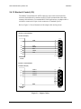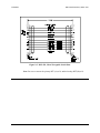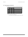
1
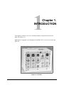
RSU-503
Redundancy Switch Unit
Installation and Operation Manual
Part Number MN/RSU503.IOM
Revision 8
Errata A
Comtech EFData Documentation Update
Subject:
Changes to Chapter 3 (Communications Link Jumper Setting)
Date:
Document:
July 28, 1997
RSU-503 Redundancy Switch Unit Installation and Operation
Manual, Rev. 8, dated April 4, 1997
MN/RSU503.EA8
Attach this page to page 3-1
Part Number:
Collating Instructions:
Comments:
The following changes provide the correct information for jumper placement when choosing
between RS-232 or -485. This information will be incorporated into the next revision.
Change Specifics:
3.4.1 Communications Link
The terminal functions can be remotely controlled and monitored via an RS-485 or RS-232
communications link.
•
The RS-485 interface makes it possible to operate 255 terminals on a common communications
link.
•
The RS-232 interface is used to communicate with a single terminal.
The M&C module must be hardware configured on the M&C board to one of the two interfaces. Refer to
the following table for jumper placement at JP1:
RS-485
Configuration
1-2
3-4
5-6
7-8
Filename: T_ERRATA
RS-232
Configuration
9-10
11-12
13-14
15-16
1
Comtech EFData is an ISO 9001 Registered Company
RSU-503
Redundancy Switch Unit
Installation and Operation Manual
Part Number MN/RSU503.IOM
Revision 8
April 4, 1997
Special Instructions:
This is the ninth edition of the manual.
Change bars were not utilized. For an overview of changes made to Rev. 7, refer to the preface
(“Overview of Changes to Previous Edition”).
This revision supersedes part number MN/SDMRSU503 Rev. 7 dated January 22, 1996.
Copyright © Comtech EFData, 2000
All rights reserved.
Printed in the USA.
Comtech EFData, 2114 West 7th Street, Tempe, Arizona 85281 USA, (480) 333-2200, FAX: (480) 333-2161.
Warranty Policy
This EFData Corporation product is warranted against defects in material and
workmanship for a period of one year from the date of shipment. During the warranty
period, EFData will, at its option, repair or replace products that prove to be defective.
For equipment under warranty, the customer is responsible for freight to EFData and
all related custom, taxes, tariffs, insurance, etc. EFData is responsible for the freight
charges only for return of the equipment from the factory to the customer. EFData will
return the equipment by the same method (i.e., Air, Express, Surface) as the
equipment was sent to EFData.
Limitations of Warranty
The foregoing warranty shall not apply to defects resulting from improper installation
or maintenance, abuse, unauthorized modification, or operation outside of
environmental specifications for the product, or, for damages that occur due to
improper repackaging of equipment for return to EFData.
No other warranty is expressed or implied. EFData Corporation specifically
disclaims the implied warranties of merchantability and fitness for particular
purpose.
Exclusive Remedies
The remedies provided herein are the buyer's sole and exclusive remedies. EFData
Corporation shall not be liable for any direct, indirect, special, incidental, or
consequential damages, whether based on contact, tort, or any other legal theory.
Disclaimer
EFData has reviewed this manual thoroughly in order that it will be an easy-to-use
guide to your equipment. All statements, technical information, and recommendations
in this manual and in any guides or related documents are believed reliable, but the
accuracy and completeness thereof are not guaranteed or warranted, and they are
not intended to be, nor should they be understood to be, representations or warranties
concerning the products described. Further, EFData reserves the right to make
changes in the specifications of the products described in this manual at any time
without notice and without obligation to notify any person of such changes.
If you have any questions regarding your equipment or the information in this manual,
please contact the EFData Customer Support Department. (For more information,
refer to the preface.)
Preface
About this Manual
This manual provides installation and operation information for the EFData RSU-503
redundancy switch unit, referred to in this manual as “the switch.” This is a technical
document intended for earth station engineers, technicians, and operators responsible for
the operation and maintenance of the RSU-503 redundancy switch unit.
Conventions and References Used in this Manual
Cautions and Warnings
CAUTIO N
CAUTION indicates a hazardous situation that, if not avoided, may result in
minor or moderate injury. CAUTION may also be used to indicate other
unsafe practices or risks of property damage.
WARNING indicates a potentially hazardous situation that, if not avoided,
could result in death or serious injury.
WARNIN G
Rev. 8
i
Preface
RSU-503 Redundancy Switch Unit
Trademarks
Product names mentioned in this manual may be trademarks or registered trademarks of
their respective companies and are hereby acknowledged.
Related Documents
The following documents are referenced in this manual:
•
•
EFData Specification SP/3000
EFData KP-10 External Keypad Installation and Operation Manual
Overview of Changes to Previous Edition
A summary of the changes made to Rev. 7 includes:
•
•
•
•
•
•
•
Incorporated various cosmetic (non-technical) changes (e.g., formatting,
spelling)
Addition of RFT-705 and KST-2000 to Section 1.1
Corrected part numbers in Section 1.2
Addition of RSU-503 dimensional drawing in Chapter 2
Corrected installation parts kit in Chapter 2
Addition of an external connection locations photos in Chapter 2 and Appendix
A
Updated firmware information in Appendix B
Reporting Comments or Suggestions Concerning this Manual
Comments and suggestions regarding the content and design of this manual will be
appreciated. To submit comments, please contact the EFData Customer Support
Department according to the following information.
ii
Rev. 8
RSU-503 Redundancy Switch Unit
Preface
Customer Support
Contact the EFData Customer Support Department for:
•
•
•
•
•
Product support
Information on returning a product
Information on upgrading a product
Product training
Reporting comments or suggestions concerning manuals
An EFData Customer Support representative may be reached at:
EFData Corporation
Attention: Customer Support Department
2105 West 5th Place
Tempe, Arizona 85281 USA
(602) 968-0447 (Main EFData Number)
(602) 517-2444 (Customer Support Desk)
(602) 921-9012 FAX
or, E-Mail can be sent to the Customer Support Department at:
[email protected]
To return an EFData product (in-warranty and out-of-warranty) for repair or
replacement:
1. Request a Return Material Authorization (RMA) number from the EFData
Customer Support Department.
Be prepared to supply the Customer Support representative with the model
number, serial number, and a description of the problem.
2. To ensure that the product is not damaged during shipping, pack the product in
its original shipping carton/packaging.
3. Ship the product back to EFData. (Shipping charges should be prepaid.)
For more information regarding the warranty policies, refer to the disclaimer page
located behind the title page.
Rev. 8
iii
Preface
RSU-503 Redundancy Switch Unit
This page is intentionally left blank.
iv
Rev. 8
Table of Contents
CHAPTER 1. INTRODUCTION.................................................................................. 1–1
1.1 Overview....................................................................................................................................................... 1–2
1.2 Assemblies .................................................................................................................................................... 1–4
1.3 Specifications................................................................................................................................................ 1–4
CHAPTER 2. INSTALLATION ................................................................................... 2–1
2.1 Unpacking..................................................................................................................................................... 2–1
2.2 Inspecting the Equipment ........................................................................................................................... 2–2
2.2.1 Included Parts......................................................................................................................................... 2–2
2.3 Switch Installation ....................................................................................................................................... 2–4
2.3.1 Tools Required ....................................................................................................................................... 2–6
2.3.2 Vertical Pole Installation ........................................................................................................................ 2–6
2.3.2.1 Round Pole...................................................................................................................................... 2–6
2.3.2.2 Square Pole ................................................................................................................................... 2–11
2.3.3 Spar Installation.................................................................................................................................... 2–12
2.4 External Connections ................................................................................................................................ 2–14
2.4.1 TX/IF Output (J1, J5) ........................................................................................................................... 2–16
2.4.2 RX/IF Input (J2, J6) ............................................................................................................................. 2–16
2.4.3 TX/RF Input (J3, J7) ............................................................................................................................ 2–16
2.4.4 M&C (J4, J8)........................................................................................................................................ 2–17
2.4.5 TX/RF Output (J9) ............................................................................................................................... 2–18
2.4.6 Waveguide Switch (J10)....................................................................................................................... 2–18
2.4.6.1 Waveguide Switch Pinout (J10).................................................................................................... 2–18
2.4.6.2 LNA Plate to Waveguide Switch .................................................................................................. 2–19
2.4.7 TX/RF Output (J11) ............................................................................................................................. 2–19
2.4.8 TX/IF Input (J12) ................................................................................................................................. 2–19
2.4.9 RX/IF Output (J13) .............................................................................................................................. 2–19
2.4.10 TX/IF Input (J14) ............................................................................................................................... 2–19
2.4.11 RX/IF Output (J15) ............................................................................................................................ 2–19
Rev. 8
v
Table of Contents
RSU-503 Redundancy Switch Unit
2.4.12 Monitor & Control (J16) .................................................................................................................... 2–20
2.4.13 GND (ERDE) ..................................................................................................................................... 2–21
2.5 External Cables.......................................................................................................................................... 2–22
2.6 Addressing.................................................................................................................................................. 2–24
CHAPTER 3. THEORY OF OPERATION .................................................................. 3–1
3.1 Power ............................................................................................................................................................ 3–1
3.2 Waveguide and Coax Switch Drivers......................................................................................................... 3–2
3.3 LNA............................................................................................................................................................... 3–2
3.4 M&C Operational Control ......................................................................................................................... 3–2
3.4.1 Communications Link ............................................................................................................................ 3–2
3.4.2 Switch Indicators.................................................................................................................................... 3–3
3.4.3 Auto/Manual Modes............................................................................................................................... 3–4
CHAPTER 4. MAINTENANCE ................................................................................... 4–1
4.1 Internal Switches ......................................................................................................................................... 4–1
4.2 Internal Indicators....................................................................................................................................... 4–2
4.3 Servicing with Power On ............................................................................................................................ 4–3
4.4 Troubleshooting ........................................................................................................................................... 4–4
4.5 Internal Connections ................................................................................................................................... 4–5
4.5.1 Serial Interfaces (J19, J20, J21) ............................................................................................................. 4–6
4.5.2 M&C Switch CMD and Indicators (J18)................................................................................................ 4–7
4.5.3 M&C Input/Output Signals (J17) ........................................................................................................... 4–8
APPENDIX A. RSU-503L OPTION ........................................................................... A–1
A.1 Description...................................................................................................................................................A–2
A.2 Assemblies....................................................................................................................................................A–2
A.3 External Connections .................................................................................................................................A–3
A.3.1 LNA Waveguide Switch Pinout (J10) ...................................................................................................A–5
A.4 External Cables ...........................................................................................................................................A–6
A.5 Addressing ...................................................................................................................................................A–7
APPENDIX B. REMOTE CONTROL OPERATION................................................... B–1
vi
Rev. 8
RSU-503 Redundancy Switch Unit
Table of Contents
B.1 General.........................................................................................................................................................B–2
B.2 Message Structure.......................................................................................................................................B–2
B.2.1 Start Character .......................................................................................................................................B–3
B.2.2 Device Address......................................................................................................................................B–3
B.2.3 Command/Response ..............................................................................................................................B–4
B.2.4 End Character ........................................................................................................................................B–4
B.3 Switch Redundancy Commands/Responses..............................................................................................B–5
B.3.1 RFT Commands/Responses ...................................................................................................................B–5
B.3.2 Configuration Commands/Responses ....................................................................................................B–5
B.3.3 Status Commands/Responses.................................................................................................................B–7
GLOSSARY ................................................................................................................g–1
INDEX .......................................................................................................................... i–1
Rev. 8
vii
Table of Contents
RSU-503 Redundancy Switch Unit
Figures
Figure 1-1.
Figure 1-2.
Figure 2-1.
Figure 2-2.
Figure 2-3.
Figure 2-4.
Figure 2-5.
Figure 4-1.
Figure 4-2.
Figure 4-3.
Figure A-1.
Figure A-2.
Figure A-3.
Figure A-4.
RSU-503 ....................................................................................................................................... 1–1
RSU-503 Interconnect Block Diagram ......................................................................................... 1–3
RSU-503 Dimensions ................................................................................................................... 2–5
RSU-503 External Connections .................................................................................................. 2–15
Adapter Cables............................................................................................................................ 2–20
RSU-503 M&C, J4 and J8 (to RFT) ........................................................................................... 2–22
RSU-503, J10 to Waveguide Switch Plate.................................................................................. 2–23
LED and Switch Locations ........................................................................................................... 4–2
Access Panel ................................................................................................................................. 4–3
Internal Connections ..................................................................................................................... 4–5
RSU-503L Front Panel.................................................................................................................A–1
RSU-503L Low Loss Block Diagram ..........................................................................................A–2
RSU-503L External Connections.................................................................................................A–4
RSU-503L, J10 to Waveguide Switches ......................................................................................A–6
Tables
Table 1-1. RSU-503 Specifications................................................................................................................. 1–4
Table 2-1. External Connections ................................................................................................................... 2–14
Table A-1. RSU-503L External Connections ..................................................................................................A–3
Table A-2. Waveguide Switch Cable Dimensions...........................................................................................A–7
viii
Rev. 8
1
Chapter 1.
INTRODUCTION
This chapter provides an overview, included assemblies, and specifications for the
RSU-503 (Figure 1-1).
Note: Refer to Appendix A for information on the RSU-503L, a low-loss version of the
RSU-503.
Figure 1-1. RSU-503
Rev. 8
1–1
Introduction
RSU-503 Redundancy Switch Unit
1.1 Overview
The switch is a fully automated 1:1 protection switch designed to work with the
following EFData Radio Frequency Terminals (and their amplifiers):
•
•
•
•
•
•
•
RFT-500
RFT-505
RFT-700
RFT-705
RFT-1200 (for RSU-503L information, refer to Appendix A)
RFT-1225 (for RSU-503L information, refer to Appendix A)
KST-2000 (for RSU-503L information, refer to Appendix A)
Note: All references in this document to “RFT” apply to all the models listed above.
The switch has a weather resistant enclosure which houses the indicators and controls to:
•
•
Switch RFTs and LNAs
Command the waveguide switch to toggle
Specifically, the switch performs the following functions:
•
Controls waveguide/coaxial switch positions
•
Provides independent uplink and downlink paths
•
Routes the IF input to the online RFT
•
Routes the IF output from the online RFT
•
Initiates a switch-over in Auto mode by monitoring RFT faults
•
Supplies test ports for testing the standby channel
•
Receives RS-232/485 serial commands, routing them to the appropriate RFTs,
and returns their responses
•
Receives its own RS-232/485 command set for Auto/Manual mode, A/B online,
and address select
•
Provides FORM-C relay contacts for Summary Fault status
Power is supplied by one or both RFTs.
1–2
Rev. 8
RSU-503 Redundancy Switch Unit
Introduction
Although there are no external indicators or switches (due to the nature of the
weatherproof housing), there is an access panel that can be removed, allowing use of
internal switches and indicators (refer to Chapter 4 for more information).
Note: The internal indicators and switches are only used for factory testing and
troubleshooting.
The system, during setup and while running, is intended to be controlled remotely.
Refer to Figure 1-2 for an interconnection block diagram of the switch.
TX/IF
CA/3005
RX/RF
RFT-xxx
#A
RX/IF
CA/3005
TX/IF
A
70 MHz
TX/IF
INPUT
70 MHz
RX/IF
OUTPUT
RS-232
REMOTE
CONTROL
J1
RX/IF
A
J14 S1 3 1
2
TNC
4
S2
31
4
M&C - RS-232
A
TX/RF
J4
P19
TNC J2
J15
TNC
CA/3004
TX/RF
CA/3003
26
TNC
CA/1530
6
IND
2
IND
6
J16
N
J11
AS/3000
S3
21
M&C
AS/3002
P21
6
TNC TNC
J12 J6
TX/IF
B
STANDBY
TX/IF
TEST
INPUT
6
6
IND
J10
RSU-503
J13 J8
LOW LOSS REDUNDANCY SWITCH UNIT
STANDBY
RF/IF
TEST
OUTPUT
CA/3003
M&C - RS-232
B
N
J7
LNA
#A
6
CA/3004
LNA
TEST
INPUT
WG TO N
ADAPTER
N
LNA
#B
FROM
ANTENNA
LNA
WAVEGUIDE
SWITCH
REDUNDANT SWITCH PLATE
26
TX/RF
RF/IF
J9
N
RF/IF
B
CA/3005
TO
ANTENNA
IND
P20
TNC TNC
J5
N
J3
4
3
RFT-xxx
#B
RX/RF
CA/3004
CA/1530
TX/IF
SHOWN WITH "B" ONLINE
Figure 1-2. RSU-503 Interconnect Block Diagram
Rev. 8
1–3
Introduction
RSU-503 Redundancy Switch Unit
1.2 Assemblies
The switch consists of the following assemblies:
Assembly
Top Assembly
RSU-503 Cable Harness
Chassis Base
Panel Divider
M&C Assembly, RSU-503
M&C Firmware, RSU-503
EFData Part #
PL/3000
PL/3001
FP/3802
FP/3139
PL/3002
FW/3080-1
1.3 Specifications
Table 1-1 lists the operating specifications for the switch.
Note: For more information pertaining to RSU-503 specifications, refer to EFData
Specification SP/3000.
Table 1-1. RSU-503 Specifications
Input power
Power consumption
Physical:
Depth
Height
Width
Weight
Environmental:
Operating Temperature
Storage Temperature
Humidity
Front Panel Controls
External Indicators
1–4
10.8V, 1A (from either RFT)
5W
7.5”
8”
11”
7.4 lbs.
-40 to +55°C
-40 to +100°C
5 to 85%, noncondensing
none
none
Rev. 8
2
Chapter 2.
INSTALLATION
This chapter provides installation instructions and external connector information for the
switch.
2.1 Unpacking
Generally, the switch and manual are shipped as part of a redundant terminal system, and
are packaged in a wooden crate along with the redundant LNA plate and cables.
1. Remove the screws from the lid of the wooden crate, and remove the lid.
2. Remove the unit and manual from the cardboard and foam enclosure.
Note: Save the packing material for reshipment.
If the switch and manual are shipped in a cardboard box:
1. Cut the tape at the top of the carton where it is indicated OPEN THIS END.
Do not use any cutting tool that will extend more than 1” into the
container and cause damage to the switch.
CAU TIO N
2. Lift the switch and manual out of the box, and remove the bubblepack and
plastic bag from the switch.
Note: Save the packing material for reshipment.
Rev. 8
1
Installation
RSU-503 Redundancy Switch Unit
2.2 Inspecting the Equipment
1. Carefully check the equipment for damage incurred during shipment.
2. Carefully check the equipment against the packing list shipped with the
equipment to ensure that the shipment is complete. Refer to the following
paragraphs.
2.2.1 Included Parts
Note: Parts are not drawn to scale.
Qty.
1
Description
RSU-503.
Qty.
1
Description
Installation and operation manual.
Note: The installation hardware listed below is included in the redundant system
installation parts kit KT/3577.
Qty.
1
Description
Spar support bracket.
Description
5/16-18 x 1” bolt.
2
EFData Part # FP/3175.
Used for spar mount only.
Unistrut — 14” long.
10
EFData Part # HW/5/16-18X1BLT.
5/16” split lockwasher.
6
EFData Part # FP/3595.
5/16-18 hex nut.
10
EFData Part # HW/5/16-SPLIT.
5/16” flat washer.
EFData Part # HW/5/16-18HEXNT.
2
Qty.
4
EFData Part # HW/5/16-FLT.
Rev. 8
RSU-503 Redundancy Switch Unit
Installation
4
Pipe block.
6
5/16-18 spring nut.
2
EFData Part # HW/BLK-PIPE2-8.
Used for round pole mount only.
Threaded rod, 5/16-18 x 14”.
4
EFData Part # HW/5/16-18SPNUT.
Flat fitting plate, 5/16”.
3
EFData Part # HW/RD5/16-18X14.
Used for round and square pole mount only.
1/4-20 x 1” bolt.
3
EFData Part # HW/FIT-PLT-5/16.
1/4” flat washer.
3
EFData Part # 03P1079.
1/4” split lockwasher.
EFData Part # O4P1022.
EFData Part # HW/1/4-SPLIT.
Rev. 8
3
Installation
RSU-503 Redundancy Switch Unit
2.3 Switch Installation
At the customer’s discretion, the switch can be installed anywhere on or near the
antenna. The supplied hardware allows the installer a wide range of installation
alternatives, including:
•
Vertical pole (e.g., mast) (either square or round). This is the most typical
installation.
•
Within the hub of a large antenna.
•
Spar (i.e., rectangular bar) on the antenna structure.
The switch is designed to be mounted with the interface connections facing the ground.
Note: For custom installations, refer to Figure 2-1 for dimensions of the RSU-503.
4
Rev. 8
RSU-503 Redundancy Switch Unit
Installation
Figure 2-1. RSU-503 Dimensions
Note: All dimensions in inches.
Rev. 8
5
Installation
6
RSU-503 Redundancy Switch Unit
Rev. 8
RSU-503 Redundancy Switch Unit
Installation
2.3.1 Tools Required
Qty.
1
Description
3/8” drive ratchet.
1
3” x 3/8” drive extension.
1
7/16” x 3/8” drive socket. (Metric equivalent: 11mm, 6 pt.)
1
1/2” x 3/8” drive socket. (Metric equivalent: 12mm, 6 pt.)
1
1/2” combination wrench. (Metric equivalent: 12mm combination
wrench with a 6 pt. box end.)
2.3.2 Vertical Pole Installation
2.3.2.1 Round Pole
The process described is for a typical installation. Custom kits may be ordered and are
beyond the scope of this manual.
Rev. 8
7
Installation
RSU-503 Redundancy Switch Unit
To install the switch to a round vertical pole:
1. Set the switch on its side, with the mounting holes facing up.
2. Install the 14” unistrut as follows:
a. Position a 14” long
unistrut (with the open
side facing up) over
the mounting holes on
the unit.
b. Using three 1/4-20 x
5/8” bolts, 1/4” split
lockwashers, and 1/4”
flat washers, attach the
unistrut to the switch.
c. Tighten the bolts
firmly.
3. Install the pipe blocks as follows:
a. Install two spring nuts in the 14” long unistrut which is mounted on the unit,
and in a second 14” long unistrut.
Be sure to center the spring nuts in the unistruts wide enough apart so that
when the pipe blocks are installed, they will clear the pole when the unit is
lifted into place for installation.
b. Install each spring nut as follows:
(1) Place the spring
nut in the unistrut
channel, spring
side down, with
its wide side
parallel with the
unistrut channel.
8
Rev. 8
RSU-503 Redundancy Switch Unit
Installation
(2) Press down on
the spring nut to
compress the
spring, and rotate
the nut 90°
(perpendicular to
the unistrut).
(3) Release pressure on the spring nut.
(4) Repeat Steps 3.b.(1) through 3.b.(3) for each spring nut.
c. Using four 5/16-18 x
1” bolts, 5/16” split
lockwashers, and
5/16” flat washers,
loosely secure the pipe
blocks to the spring
nuts in each 14”
unistrut.
Ensure the pipe blocks
are installed with the
long angle facing
inward, toward the
pipe, as illustrated.
DO NOT tighten the
pipe block bolts until
after mounting the
switch on the vertical
pole (see Step 5.e.).
4. Install the threaded rods as follows:
a. Install two spring nuts in the 14” long unistruts mounted on the unit.
Note: Ensure the spring nuts are positioned over the outer holes in the long
unistruts.
Rev. 8
9
Installation
RSU-503 Redundancy Switch Unit
b. To install each spring
nut:
(1) Place the spring
nut in the unistrut
channel, spring
side down, with
its wide side
parallel with the
unistrut channel.
(2) Press down on
the spring nut to
compress the
spring, and rotate
the nut 90°
(perpendicular to
the unistrut).
(3) Release pressure on the spring nut.
(4) Repeat Steps 4.b.(1) through 4.b.(3) for each spring nut.
c. Thread a 5/16-18 nut approximately 1-1/2” onto each threaded rod. (This
will ensure that the threaded rods will extend beyond the spring nuts when
installed.)
d. Place a 5/16” split
lockwasher, 5/16” flat
washer, and flat fitting
plate over each
threaded rod.
e. One threaded rod at a
time, hold the washers
and plate in place on
the threaded rod and
screw it into a spring
nut, as illustrated.
10
Rev. 8
RSU-503 Redundancy Switch Unit
Installation
Notes:
1. Be sure to position the flanges of the fitting plates in the grooves of
the unistruts.
2. Before tightening the nuts on the threaded rods, ensure that the end
of each rod is screwed in until it is flush with the backside of the
unistrut. This ensures the rods are threaded completely through the
spring nuts.
Tighten each nut firmly.
f.
Thread a 5/16-18 nut
about 2” onto the end
of each threaded rod.
g. Slip a 5/16” split
lockwasher, 5/16” flat
washer and flat fitting
plate (in that order)
onto each threaded
rod.
5. Mount the unit as follows:
a. Lift the unit into position on the vertical pole.
b
Slip the 14” unistrut
over the threaded rods
(upper and lower).
Note: Install the 14”
unistrut with its open
face toward the pole.
c. Install a 5/16” flat
washer, 5/16” split
lockwasher, and
5/16-18 nut on each
threaded rod.
d.
Position the unit as desired, and tighten the 5/16-18 nuts installed in Step
5.c.
e. Slide the pipe blocks inward until they contact the vertical pole, then firmly
tighten the 5/16-18 bolts.
Rev. 8
11
Installation
RSU-503 Redundancy Switch Unit
2.3.2.2 Square Pole
For square vertical pole installation, follow the steps in Section 2.3.2.1, with the
following exceptions:
•
•
12
Do not perform Step 3.
Do not perform Step 5.e.
Rev. 8
RSU-503 Redundancy Switch Unit
Installation
2.3.3 Spar Installation
Note: The process described is for a typical installation. Custom kits may be ordered and
are beyond the scope of this manual.
To install the switch to a spar:
1. Set the unit on its side, with the mounting holes facing up.
2. Install a 14” unistrut.
a. Position a 14” unistrut (with the open side facing up) over the mounting
holes on the switch.
b. Using three 1/4-20
bolts, 1/4” split
lockwashers, and 1/4”
flat washers, attach the
unistrut to the switch.
c. Tighten the bolts firmly.
3. Mount the switch as follows:
a. Install two spring nuts in the unistrut (centered on the unistrut, the width of
the spar bracket holes).
b. To install each spring nut:
(1) Place the spring
nut in the unistrut
channel, spring
side down, with
its wide side
parallel with the
unistrut channel.
(2) Press down on
the spring nut to
compress the
spring, and rotate
the nut 90° (i.e.,
perpendicular to
the unistrut).
Rev. 8
13
Installation
RSU-503 Redundancy Switch Unit
(3) Release pressure on the spring nut.
(4) Repeat Steps 3.b.(1) through 3.b.(3) for each spring nut.
c. Lift the switch into position.
d. Using two 5/16-18
bolts, 5/16” split
lockwashers, and
5/16” flat washers,
bolt the spar bracket in
place.
d. Tighten the bolts
firmly.
14
Rev. 8
RSU-503 Redundancy Switch Unit
Installation
2.4 External Connections
All connections between the switch and other equipment are made through front panel
connections, as shown in Table 2-1 (refer to Figure 2-2 for connector locations).
Failure to properly connect the units will result in loss of communications
between the switch and the RFTs.
CAU TIO N
Table 2-1. External Connections
Name
TX/IF OUTPUT
RX/IF INPUT
TX/RF INPUT
MONITOR &
CONTROL
TX/IF OUTPUT
RX/IF INPUT
TX/RF INPUT
MONITOR &
CONTROL
TX/RF OUTPUT
WAVEGUIDE
SWITCH
TX/RF OUTPUT
TX/IF INPUT
RX/IF OUTPUT
TX/IF INPUT
RX/IF OUTPUT
MONITOR &
CONTROL
GND ERDE
Desig.
Type
Function
Switch to RFT #A (Primary)
J1
TNC, 50Ω
IF Uplink to Unit A
J2
TNC, 50Ω
IF Downlink from Unit A
J3
N
TX Uplink from Unit A
J4
26-pin Circ.
Monitor and control
See Section 2.4.4 for pinouts
Switch to RFT #B (Backup)
J5
TNC, 50Ω
IF Uplink to Unit B
J6
TNC, 50Ω
IF Downlink from Unit B
J7
N
TX Uplink from Unit B
J8
26-pin Circ.
Monitor and control
See Section 2.4.4 for pinouts
Switch to Antenna
J9
N
TX Uplink from online unit
J10
19-pin Circ.
Waveguide switch control
See Section 2.4.6.1 for pinouts
Standby Unit Test Ports
J11
N
TX output test signal
J12
TNC, 50Ω
IF input test signal
J13
TNC, 50Ω
IF output test signal
Switch to Modem Terminal Interface
J14
TNC, 50Ω
IF Uplink
J15
TNC, 50Ω
IF Downlink
J16
26-pin Circ.
Modem Terminal Interface (MTI)
See Section 2.4.12 for pinouts
Ground
None
#10-32 Stud
Chassis Ground
(See note)
(See note)
Note: Refer to Section 2.6 for addressing information.
Rev. 8
15
Installation
RSU-503 Redundancy Switch Unit
Figure 2-2. RSU-503 External Connections
16
Rev. 8
RSU-503 Redundancy Switch Unit
Installation
2.4.1 TX/IF Output (J1, J5)
The TX/IF Output connectors are TNC connectors, each with an impedance of 50Ω.
These connectors carry the IF uplink signal to the online RFT (Unit A or B).
2.4.2 RX/IF Input (J2, J6)
The RX/IF Input connectors are TNC connectors, each with an impedance of 50Ω. These
connectors carry the IF downlink signal from the online RFT (Unit A or B).
2.4.3 TX/RF Input (J3, J7)
The TX/RF Input connectors are type N connectors, each with an impedance of 50Ω.
These connectors carry the transmit uplink signal from the online RFT (Unit A or B).
Rev. 8
17
Installation
RSU-503 Redundancy Switch Unit
2.4.4 M&C (J4, J8)
The M&C connectors are used to interface with Units A and B, respectively. Included on
these connectors are:
•
•
•
Nine RS-232/485 communication pins (A to J)
Switch power (L)
Fault reporting
The M&C connectors are 26-pin circular female connectors, with the following pinouts:
Pin #
A
B
C
D
E
F
G
H
J
K
L
M
N
P
R
S
T
U
V
W
X
Y
Z
a
b
c
Name
RS-232
GND
CTS
TD/TX
RTS
RD/RX
DSR
LNA POWER
EXT POWER
EXT FLT IN
Reserved
N/C
GND
Chassis Ground
Reserved
UL FLT NC
UL FLT COM
UL FLT NO
DL FLT NC
DL FLT COM
DL FLT NO
LNA RTN
Reserved
Reserved
RS-485
-RX/TX
-RX/TX
+RX/TX
+RX/TX
Function
Clear to Send
Transmit Data
Ready to Send
Receive Data
Data Set Ready
Ground
GND
10V to LNA
Input Voltage, 11V, 1A max.
Fault Input from TWT
Ground
Ground
Fault relay input, closes with Uplink fault
Fault relay input, COMMON
Fault relay input, opens with Uplink fault
Fault relay input, closes with Downlink fault
Fault relay input, COMMON
Fault relay input, opens with Downlink fault
Ground return from LNA
Notes:
1. Clear to Send (CTS) is tied to Ready to Send (RTS) in RS-232 mode.
2. RD/RX and TD/TX are switched in the switch in order to communicate with
the RFTs.
18
Rev. 8
RSU-503 Redundancy Switch Unit
Installation
2.4.5 TX/RF Output (J9)
The TX/RF Output connector is a 50Ω type N connector that carries the transmit uplink
signal from the online RFT (Unit A or B) to the antenna.
2.4.6 Waveguide Switch (J10)
The Waveguide Switch connector connects the switch to the LNA plate using a 1:1
cable.
2.4.6.1 Waveguide Switch Pinout (J10)
The Waveguide Switch connector uses a 19-pin circular female connector with the
following pinouts:
Name
LNA Position 1 Command
LNA Command Common
LNA Position 2 Command
LNA Indicator, Position 1
LNA Indicator, Common
LNA Indicator, Position 2
RF Position 1 Command
RF Command Common
RF Position 2 Command
RF Indicator, Position 1
RF Indicator, Common
RF Indicator, Position 2
LNA PWR #A
LNA RTN #A
LNA PWR #B
LNA RTN #B
Rev. 8
Pin #
C
G
D
H
R
T
E
L
F
J
V
K
A
B
N
P
Function
+28V pulse for 500 milliseconds
Ground
+28V pulse for 500 milliseconds
Connects to Common when in position 1
Ground
Connects to Common when in position 2
+28V pulse for 500 milliseconds
Ground
+28V pulse for 500 milliseconds
Connects to Common when in position 1
Ground
Connects to Common when in position 2
19
Installation
RSU-503 Redundancy Switch Unit
2.4.6.2 LNA Plate to Waveguide Switch
The following table outlines the pinouts of the LNA plate to Waveguide Switch cable.
This cable is internal on the redundant LNA plate.
Note: This pinout table may be helpful if an EFData Waveguide Switch is used.
Name
Command, Position 1
Command Common
Command, Position 2
Indicator, Position 1
Indicator Common
Indicator, Position 2
Pin #
A
B
C
D
E
F
Function
+28V pulse for 500 milliseconds
Ground
+28V pulse for 500 milliseconds
Connects to Common when in position 1
Ground
Connects to Common when in position 2
2.4.7 TX/RF Output (J11)
The TX/RF Output connector is a 50Ω type N connector used to monitor the transmit
output signal from the offline RFT. This connector is used to test the offline unit.
2.4.8 TX/IF Input (J12)
The TX/IF Input connector is a 50Ω TNC connector used to input the IF test signal to the
offline RFT. This connector is used to test the offline unit.
2.4.9 RX/IF Output (J13)
The RX/IF Output connector is a 50Ω TNC connector used to monitor the IF output
signal from the offline RFT. This connector is used to test the offline unit.
2.4.10 TX/IF Input (J14)
The TX/IF Input connector is a 50Ω TNC connector used to receive the IF uplink signal
from the modem. The switch routes the signal to the online RFT for transmission.
2.4.11 RX/IF Output (J15)
The RX/IF Output connector is a 50Ω TNC connector used to provide the IF downlink
signal to the modem (after the signal is picked up by the antenna and routed through the
online LNA and RFT).
20
Rev. 8
RSU-503 Redundancy Switch Unit
Installation
2.4.12 Monitor & Control (J16)
The Modem Terminal Interface (MTI) connector is the remote control interface
connector. Included on this connector are RS-232/485 communication lines and a
summary fault indication. For standard RS-232/485 applications, an adapter cable is
available to connect the 26-pin circular connector to a standard 9-pin D.
Refer to Figure 2-3 for an illustration of the adapter cable and its pinouts.
EFDATA: CN/STPG26M01
PT06E16-26P(SR)
P1
GND
A
CTS
RD/RX
RTS
TD/TX
DSR
D
E
F
G
H
5
9
4
8
3
7
2
6
1
26 PIN
MALE
EFDATA: CN/STPG26M01
PT06E16-26P(SR)
P1
A
B
C
D
J
-RX/TX
-RX/TX
+RX/TX
+RX/TX
GND
26 PIN
5
9
4
8
3
7
2
6
1
MALE
Figure 2-3. Adapter Cables
Rev. 8
21
Installation
RSU-503 Redundancy Switch Unit
The MTI connector is a 26-pin circular female connector with the following pinouts:
Pin #
A
B
C
D
E
F
G
H
J
K
L
M
N
P
R
S
T
U
V
W
X
Y
Z
a
b
c
Name
RS-232
GND
CTS
RD/RX
RTS
TD/TX
DSR
RS-485
-RX/TX
-RX/TX
+RX/TX
+RX/TX
GND
Reserved
EXT_PWR
EXT FLT1 #A
EXT FLT1 #B
N/C
Ground
Reserved
Reserved
Reserved
Reserved
FLT NC
FLT COM
FLT NO
Reserved
Reserved
Reserved
Function
Clear to Send
Receive Data
Ready to Send
Transmit Data
Data Set Ready
Ground
Output, 11V for KP-10
TWT FLT input for primary channel
TWT FLT input for secondary channel
Chassis Ground
Summary fault relay, connects to COM with fault
Summary fault relay, COMMON
Summary fault relay, opens with fault
Note: Clear to Send (CTS) is tied to Ready to Send (RTS) in RS-232 mode.
2.4.13 GND (ERDE)
GND is a #10-32 stud for the purpose of connecting all units to a common chassis
ground.
22
Rev. 8
RSU-503 Redundancy Switch Unit
Installation
2.5 External Cables
Refer to Figures 2-4 and 2-5 for diagrams of the two different external multi-conductor
cables used with the switch in a redundant system.
Figure 2-4. RSU-503 M&C, J4 and J8 (to RFT)
Rev. 8
23
Installation
RSU-503 Redundancy Switch Unit
Figure 2-5. RSU-503, J10 to Waveguide Switch Plate
Note: Be sure to connect the primary RFT (A) to J4, and the backup RFT (B) to J8.
24
Rev. 8
RSU-503 Redundancy Switch Unit
Installation
2.6 Addressing
The following are the factory default addresses:
•
•
•
Switch is set to address 1
RFT A is set to address 2
RFT B is set to address 3
The proper M&C cable hook-up is critical:
•
•
RFT A must be connected to the switch Port A
RFT B must be connected to the switch Port B
Note: If these connections are reversed, no communications will take place.
Rev. 8
25
3
Chapter 3.
THEORY OF OPERATION
This chapter provides the basic theory for the following:
•
•
•
•
Switch power
Waveguide and coax switch drivers
LNA
M&C operational control
3.1 Power
In a redundant system, the switch is powered from either of the two RFT terminals via
the M&C interconnect cable. External DC power (approximately 10.8V) enters the M&C
on pins 1 and 2 of connector J17 (25-pin D), and is “ORed” through diodes CR1 and
CR2.
The switch is monitored by the analog-to-digital (A/D) converter U16, and is made
available as a maintenance status through the serial terminal.
A 3-terminal regulator, U1, converts and regulates the +5V to all the logic, including the
microcontroller U18.
PS1 converts the 10V input voltage to 30V, where it is stored by capacitors C6 through
C10 to supply the 500 millisecond pulses to the transfer switches.
Rev. 8
3–1
Theory of Operation
RSU-503 Redundancy Switch Unit
3.2 Waveguide and Coax Switch Drivers
The microcontroller creates the 500 millisecond pulses to control the positions of all four
transfer switches. Photovoltaic opto-isolated switches U8, U9, U10, and U11 transform
the +5V logic into 30V pulses to drive the latching coils of the switches.
Each microwave transfer switch contributes 0.3 dB of insertion loss, with a minimum of
70 dB of isolation.
3.3 LNA
The LNAs are powered directly from their respective RFTs through the RF coax cable.
The RFT performs a current sense on its LNA, and informs the switch by declaring a
downlink fault, if one is detected.
3.4 M&C Operational Control
3.4.1 Communications Link
The terminal functions can be remotely controlled and monitored via an RS-485 or
RS-232 communications link.
•
The RS-485 interface makes it possible to operate 255 terminals on a common
communications link.
•
The RS-232 interface is used to communicate with a single terminal.
The M&C module must be hardware configured on the M&C board to one of the two
interfaces. Refer to the following table for jumper placement at JP3:
RS-485
Configuration
1-2
3-4
5-6
7-8
3–2
RS-232
Configuration
9-10
11-12
13-14
15-16
Rev. 8
RSU-503 Redundancy Switch Unit
Theory of Operation
Although the switch M&C is considered to be the slave unit on the MTI RS-232 bus, it
becomes the master when communicating to each of the two RFTs.
When not servicing MTI requests, the M&C monitors indicators, faults, and voltages.
When applicable, it generates switch-over pulses.
When polled from the MTI, the switch M&C will perform the following functions:
1. Return a response acknowledging receipt of the command.
2. Decode the address in the message, compare it to the stored addresses, and route
it to its intended destination.
3. Return a block of status information when requested.
3.4.2 Switch Indicators
Address 9000 reads in the eight indicator bits representing the four uplink and four
downlink indicator positions. The following tables show how the four bits are decoded to
indicate whether the unit A or B is currently online.
Rev. 8
B0
IF_A
B1
RF_A
B2
IF_B
B3
RF_B
0
0
0
0
0
0
0
0
1
1
1
1
1
1
1
1
0
0
0
0
1
1
1
1
0
0
0
0
1
1
1
1
0
0
1
1
0
0
1
1
0
0
1
1
0
0
1
1
0
1
0
1
0
1
0
1
0
1
0
1
0
1
0
1
Uplink
WR8000, B0
1 = A ON LINE
0 = B ON LINE
1
1
1
1
0
0
0
0
1
1
1
1
0
0
0
0
WR8000, B4
1 = OKAY
0 = AMBIGUITY FAULT
0
0
0
1 - Valid state, A online
0
0
0
0
0
0
0
0
1 - Valid state, B online
0
0
0
3–3
Theory of Operation
RSU-503 Redundancy Switch Unit
B4
IF_A
B5
RF_A
B6
IF_B
0
0
0
0
0
0
0
0
1
1
1
1
1
1
1
1
0
0
0
0
1
1
1
1
0
0
0
0
1
1
1
1
0
0
1
1
0
0
1
1
0
0
1
1
0
0
1
1
Downlink
B7
WR8000, B2
RF_B
1= A ON LINE
0 = B ON LINE
0
1
1
1
0
1
1
1
0
0
1
0
0
0
1
0
0
1
1
1
0
1
1
1
0
0
1
0
0
0
1
0
WR8000, B5
1 = OKAY
0 = AMBIGUITY FAULT
0
0
0
1 - Valid state, A online
0
0
0
0
0
0
0
0
1 - Valid state, B online
0
0
0
3.4.3 Auto/Manual Modes
In Auto mode, switch-over can only occur as a result of a fault, as listed in the following
table:
RD9001
B0
UL FLT A
0
0
1
1
B1
UL FLT B
0
1
0
1
B2
DL FLT A
0
0
1
1
B3
DL FLT B
0
1
0
1
Fault Description
No faults.
Fault on B uplink, switch to uplink A, WR8001 B0.
Fault on A uplink, switch to uplink B, WR8001 B1.
Fault on both, do nothing. Monitor, and switch to the first
unit to remote the fault.
Fault Description
No faults.
Fault on B downlink, switch to downlink A, WR8001 B2.
Fault on A downlink, switch to downlink B, WR8001 B3.
Fault on both, do nothing. Monitor, and switch to the first
unit to remote the fault.
In Manual mode, the switch initiates the online pulses from only two sources:
•
•
Request from the MTI
Onboard push-button switches
In normal service with the cover secured, switch-over can occur only from an MTI
request.
3–4
Rev. 8
4
Chapter 4.
MAINTENANCE
This chapter provides information on the following:
•
•
•
Internal switches, indicators, and connections
How to service the switch with the power on
Troubleshooting
Note: Under normal conditions, this switch does not require periodic or preventive
maintenance. Most problems, if any, will arise during the initial installation. These
problems will most often be due to improper cabling, waveguide wiring, or indicator
positions.
4.1 Internal Switches
The switch does not have any external switches or controls. The internal switches
(shown in Figure 4-1) are not normally used by the operator. However, if the switch must
be opened, descriptions of the four push-button switches are provided in the following
table.
Switch
UL AUTO/MAN
UL A/B ONLINE
DL AUTO/MAN
DL A/B ONLINE
Rev. 8
Description
Depress to alternate between Uplink Auto and Manual.
Depress to alternate between A and B uplink online.
Depress to alternate between downlink Auto and Manual.
Depress to alternate between A and B downlink online.
4–1
Maintenance
RSU-503 Redundancy Switch Unit
4.2 Internal Indicators
The switch does not have any external indicators. The internal indicators (shown in
Figure 4-1) are not normally used by the operator. However, if the switch must be
opened, descriptions of the indicators are provided in the following table.
Indicator
LED
PWR A
PWR B
32V
SUM FLT
Green
Green
Green
Red
FLT A
FLT B
FLT AMB
B OL
MAN
Red
Red
Red
Yellow
Yellow
FLT A
FLT B
FLT AMB
B OL
MAN
Red
Red
Red
Yellow
Yellow
Cause
System Status
Illuminates if RFT A power is available.
Illuminates if RFT B power is available.
Illuminates when power available to switches.
Illuminates an ambiguity failure, RFT fault, or power supply
fault.
Uplink
Illuminates with failure of unit A uplink.
Illuminates with failure of unit B uplink.
Illuminates if uplink switch indicators do not agree.
Illuminates when unit B uplink is online.
Illuminates when uplink is in manual mode.
Downlink
Illuminates with failure of unit A downlink.
Illuminates with failure of unit B downlink.
Illuminates if downlink switch indicators do not agree.
Illuminates when unit B downlink is online.
Illuminates when downlink is in manual mode.
Figure 4-1. LED and Switch Locations
4–2
Rev. 8
RSU-503 Redundancy Switch Unit
Maintenance
4.3 Servicing with Power On
If maintenance must be performed on the unit while the link remains on the air, proceed
as follows:
1. Loosen the access panel screws on the side of the switch case (refer to
Figure 4-2) to expose the internal M&C Logic Control PCB.
Figure 4-2. Access Panel
2. Observe the LEDs on the M&C board, which will indicate the following:
a.
b.
c.
d.
e.
f.
g.
h.
i.
j.
k.
l.
m.
n.
Receipt of power from RFT A
Receipt of power from RFT B
Transfer switch power (32V) available
Summary fault indicator, if any fault in the system
Uplink RFT, Unit A fault
Uplink RFT, Unit B fault
Uplink Indicator Ambiguity fault
Uplink unit A or B currently online
Uplink mode in Auto or Manual
Downlink RFT, Unit A fault
Downlink RFT, Unit B fault
Downlink Indicator Ambiguity fault
Downlink unit A or B currently online
Downlink mode in Auto or Manual
3. Refer to Section 4.4 for troubleshooting assistance.
Rev. 8
4–3
Maintenance
RSU-503 Redundancy Switch Unit
4.4 Troubleshooting
The following paragraphs may be used to diagnose problems within the system. Locate
the malfunction in the left column that most closely matches the situation. Then, read
across to the possible problem.
All conditions except the first can be observed only when the cover of the switch is
removed.
Refer to Figure 4-1 for LED locations.
Condition
Cannot initiate switch-over from A
to B, or vice versa
PWR A LED not lit
PWR B LED not lit
32V LED not lit
UL or DL Unit A fault LED lit
UL or DL Unit B fault LED lit
UL or DL Ambiguity Fault LED lit
Summary fault LED lit
4–4
Possible Problem
System could be in AUTO mode, where switch-overs
are automatic.
Cable not connected from RFT A.
RFT A not powered up.
Cable not connected from RFT B.
RFT B not powered up.
DC/DC module PS1 bad on M&C board.
Short on output of module PS1.
RFT A has a fault in either the UL or DL. Cable from
RFT A disconnected, or RFT A turned off.
RFT B has a fault in either the UL or DL. Cable from
RFT B disconnected, or RFT B turned off.
IF and RF transfer switches (input/output) are not in
sync. Use remote terminal, or M&C push-buttons to
alternate between A and B online. This will synchronize
the pair.
Request Fault Status from remote terminal to ascertain
the specific fault from fault list.
Rev. 8
RSU-503 Redundancy Switch Unit
Maintenance
4.5 Internal Connections
The internal connections are not normally seen by the user, since the switch is designed
to prevent the weather from damaging the internal circuitry. However, if the switch must
be opened, pinouts of the three internal connectors have been provided.
Refer to Figure 4-3 for location of the internal connections.
Figure 4-3. Internal Connections
Rev. 8
4–5
Maintenance
RSU-503 Redundancy Switch Unit
4.5.1 Serial Interfaces (J19, J20, J21)
The internal Serial Interface connectors are 9-pin D with the following pinouts:
Pin #
1
2
3
4
5
6
7
8
9
Name
RS-232
RS-485
GND
TD/TX
RD/RX
+RX/TX
GND
DSR
RTS
-RX/TX
CTS
-RX/TX
Function
Transmit Data
Receive Data
Data Set Ready (Tied high)
Ready to Send
Clear to Send
(see Note 1)
(see Note 2)
(see Note 2)
Notes:
1. J19 and J20 do not use DSR on pin 6.
2. Clear to Send (CTS) is tied to Ready to Send (RTS) in RS-232 mode.
4–6
Rev. 8
RSU-503 Redundancy Switch Unit
Maintenance
4.5.2 M&C Switch CMD and Indicators (J18)
This connector is a 37-pin female D connector with the following pinouts:
Pin #
1
20
2
21
3
22
4
23
5
24
6
25
7
26
8
27
9
28
10
29
11
30
12
31
13
32
14
33
15
34
16
35
17
36
18
37
19
Rev. 8
Name
Terminal Power
Spare
UL IF IND COM
DL IF IND COM
UL RF IND COM
DL RF IND COM
Spare
UL IF A IND
UL IF B IND
Spare
UL RF A IND
UL RF B IND
Spare
DL IF A IND
DL IF B IND
Spare
DL RF A IND
DL RF B IND
Spare
Spare
Spare
UL IF A CMD
UL RF A CMD
Spare
UL IF B CMD
UL RF B CMD
Spare
DL IF A CMD
DL RF A CMD
Spare
DL IF B CMD
DL RF B CMD
Spare
UL IF CMD COM
UL RF CMD COM
DL IF CMD COM
DL RF CMD COM
Function
Output, 10V power for the KP-10
Tied to signal ground
Tied to signal ground
Tied to signal ground
Tied to signal ground
0V = Indicates uplink IF connected to unit A
0V = Indicates uplink IF connected to unit B
0V = Indicates uplink RF connected to unit A
0V = Indicates uplink RF connected to unit B
0V = Indicates downlink IF connected to unit A
0V = Indicates downlink IF connected to unit B
0V = Indicates downlink RF connected to unit A
0V = Indicates downlink RF connected to unit B
+28V pulse, commands UL IF switch to unit A
+28V pulse, commands UL RF switch to unit A
+28V pulse, commands UL IF switch to unit B
+28V pulse, commands UL RF switch to unit B
+28V pulse, commands DL IF switch to A
+28V pulse, commands DL RF switch to unit A
+28V pulse, commands DL IF switch to unit B
+28V pulse, commands DL RF switch to unit B
Tied to signal ground
Tied to signal ground
Tied to signal ground
Tied to signal ground
4–7
Maintenance
RSU-503 Redundancy Switch Unit
4.5.3 M&C Input/Output Signals (J17)
The M&C I/O connector is a 25-pin male D connector with the following pinouts:
Pin #
13
25
12
24
11
23
10
22
9
21
8
20
7
19
6
18
5
17
4
16
3
15
2
14
1
4–8
Name
DC GND A
DC GND B
UL FLT COM A
UL FLT COM B
DL FLT COM A
DL FLT COM B
Spare
UL FLT NO A
UL FLT NC A
UL FLT NO B
UL FLT NC B
Spare
DL FLT NO A
DL FLT NC A
DL FLT NO B
DL FLT NC B
Spare
Spare
SUM FLT NO
SUM FLT COM
SUM FLT NC
Spare
XVA
Spare
XVB
Function
Tied to signal ground
Tied to signal ground
Tied to signal ground
Tied to signal ground
Tied to signal ground
Tied to signal ground
Input, connected to ground when normal
Input, connected to ground when faulted
Input, connected to ground when normal
Input, connected to ground when faulted
Input, connected to ground when normal
Input, connected to ground when faulted
Input, connected to ground when normal
Input, connected to ground when faulted
Output, connected to COM when normal
Output common
Output, connected to COM with any fault
Input, DC power from unit A (approx. 11V)
Input, DC power from unit B (approx. 11V)
Rev. 8
A
Appendix A.
RSU-503L OPTION
This appendix describes the RSU-503L (Figure A-1), a low-loss version of the RSU-503.
Note: The RSU-503 and RSU-503L are similar units. As a result, only the primary
differences of the RSU-503L are provided in this appendix.
Figure A-1. RSU-503L Front Panel
Rev. 8
A–1
RSU-503L Option
RSU-503 Redundancy Switch Unit
A.1 Description
Refer to Figure A-2 for an interconnection block diagram of the RSU-503L in a typical
earth station application.
Using WR229 (C-band) or WR75 (Ku-band) waveguide, the RSU-503L routes the RF
outputs from both RFTs directly to a waveguide switch on the antenna plate.
In addition to the RSU-503 functions, the RSU-503L provides command pulses for the
external uplink waveguide switch (28V).
A.2 Assemblies
The RSU-503L consists of the following assemblies:
Assembly
Top Assembly
Cable Harness
Chassis Base
Panel Divider
M&C Assembly, RSU-503L
M&C Firmware, RSU-503L
C A /3 0 0 5
T X / IF
R X / IF
TN C
TN C
C A /3 0 0 5
26
T X /IF
A
70 M Hz
T X /IF
IN P U T
J1 4
TN C
S 1 3
1
TN C
J 1
R X / IF
A
TN C
RS232
R E M O TE
C O N TR O L
2
4
J1 5
T X /R F
1
C A /3 0 0 3
M & C- R S 2 3 2
A
J4
A S /3 0 0 0 - 1
S3
3
6 IND
4
M & C
12
WG
J10
LN A
TE S T
IN P U T
TN C
TN C
J12 J6
J1 3 J 8
R S U -5 0 3 L
R F /IF
LOW LOSS REDUNDANCY SWITCH UNIT
S TA N D B Y
B
T X / IF
R F /IF
T X / IF
TN C
TN C
SHO W N
W IT H
6
6
LN A
W A V E G U ID E
S W IT C H
REDUNDANT
T X / RF
S W IT C H
P LA TE
W A V E G U ID E
R X /R F
" B "
FROM ANTENNA
WG T O N
A D A P TE R
N LN A
#B
C A /3 0 0 3
M & C -R S 2 3 2
B
R F T-X X X
#B
A S /2 5 7 8
TO ANTENNA
1
19
IND
TN C
J5
C /A 3 0 0 5
UPLINK
W A V E G U ID E
S W IT C H
N LN A
#A
P20
S TA N D B Y
R F / IF
TE S T
O U TP U T
26
2
CA/3951
A S /3 0 0 2
P 2 1
J16
TE S T
IN P U T
4
3
IND
2
T X / IF
B
W A V E G U ID E
6
TN C
TN C
C A /1 5 3 0
R X /R F
R F T-X X X
#A
A S /2 5 7 8
P19
S 2
70 M Hz
R X / IF
O U TPU T
J2
EFData Part #
PL/3000-1
PL/3001-1
FP/3802
FP/3139
PL/3002
FW/3080-1
C A /1 5 3 0
ONL IN E
Figure A-2. RSU-503L Low Loss Block Diagram
A–2
Rev. 8
RSU-503 Redundancy Switch Unit
RSU-503L Option
A.3 External Connections
Note: The following connections, available on the RSU-503, are not available with the
RSU-503L:
•
•
•
TX/RF Input (J3, J7)
TX/RF Output (J9)
TX/RF Output (J11) (test output only)
Failure to properly connect the units will result in loss of communications
between the switch and the RFTs.
CAUTIO N
All connections between the switch and other equipment are made through front panel
connections, as shown in Table A-1 (refer to Figure A-3 for connector locations).
Table A-1. RSU-503L External Connections
Name
TX/IF OUTPUT
RX/IF INPUT
MONITOR &
CONTROL
TX/IF OUTPUT
RX/IF INPUT
MONITOR &
CONTROL
WAVEGUIDE
SWITCH
TX/IF INPUT
RX/IF OUTPUT
TX/IF INPUT
RX/IF OUTPUT
MONITOR &
CONTROL
GND ERDE
Desig.
Type
Function
Switch to RFT #A (Primary)
J1
TNC, 50Ω
IF Uplink to Unit A
J2
TNC, 50Ω
IF Downlink from Unit A
J4
26-pin Circ.
Monitor and control
See Section 2.4.4 for pinouts
Switch to RFT #B (Backup)
J5
TNC, 50Ω
IF Uplink to Unit B
J6
TNC, 50Ω
IF Downlink from Unit B
J8
26-pin Circ.
Monitor and control
See Section 2.4.4 for pinouts
Switch to Antenna
J10
19-pin Circ.
Waveguide switch control
See Section 2.4.6.1 for pinouts
Standby Unit Test Ports
J12
TNC, 50Ω
IF input test signal
J13
TNC, 50Ω
IF output test signal
Switch to Modem Terminal Interface
J14
TNC, 50Ω
IF Uplink
J15
TNC, 50Ω
IF Downlink
J16
26-pin Circ.
Modem Terminal Interface (MTI)
See Section 2.4.12 for pinouts
Ground
None
#10-32 Stud
Chassis Ground
(See note)
(See note)
Note: Refer to Section A.5 for addressing information.
Rev. 8
A–3
RSU-503L Option
RSU-503 Redundancy Switch Unit
Figure A-3. RSU-503L External Connections
A–4
Rev. 8
RSU-503 Redundancy Switch Unit
RSU-503L Option
A.3.1 LNA Waveguide Switch Pinout (J10)
Name
Command, LNA Position 1
LNA Command Common
Command, LNA Position 2
LNA Indicator, Position 1
LNA Indicator, Common
LNA Indicator, Position 2
Command, RF Position 1
RF Command Common
Command, RF Position 2
RF Indicator, Position 1
RF Indicator, Common
RF Indicator, Position 2
LNA PWR #A
LNA RTN #A
LNA PWR #B
LNA RTN #B
Chassis Ground
Rev. 8
Pin #
C
G
D
H
R
T
E
L
F
J
V
K
A
B
N
P
S
Function
+28V pulse for 500 milliseconds
Ground
+28V pulse for 500 milliseconds
Connects to Common when in position 1
Ground
Connects to Common when in position 2
+28V pulse for 500 milliseconds
Ground
+28V pulse for 500 milliseconds
Connects to Common when in position 1
Ground
Connects to Common when in position 2
10V power for LNA 1
Ground Return for LNA 1
10V power for LNA 2
Ground Return for LNA 2
Ground for Shields
A–5
RSU-503L Option
RSU-503 Redundancy Switch Unit
A.4 External Cables
Refer to Figure A-4 for a diagram of the waveguide switch cable and Table A-2 for cable
dimensions.
DIMENSION "A"
SEE TABLE
28P1040
PTO6E-14-19S (SR)
CABLE: 30P1034
NQ-1922SJ
28P1038
PTO6E-14-19P (SR)
A
M
B
N
U
BLK-WHT
LNA1 PWR
WHT
SPARE1
BRN-WHT
LNA RTN
BRN
LNA2 PWR
BLU
SPARE2
RED
LNA2 RTN
RED-WHT
DLPOS1 CMD
P
C
G
D
H
R
T
GRN-WHT
DLCMD COM
ORN-WHT
DLPOS2 CMD
VIO-WHT
DLPOS1 IND
ORN
DLIND COM
YEL
DLPOS2 IND
A
M
B
N
U
P
C
G
D
H
R
T
GRN
GRN
S
E
L
F
J
V
K
MATES TO
ANTENNA BULKHEAD
CONN. 28P1041
PT00E-14-19P (SR)
S
ULPOS1 CMD
ULCMD COM
ULPOS2 CMD
ULPOS1 IND
ULIND COM
ULPOS2 IND
A
B
C
U/L W G SW
D
E
(CONNECTOR SUPPLIED
W ITH W G SW ITCH)
CN/STPG06F02
F
CABLE:30P1054
BELDON 9260
DIMENSION "B"
SEE TABLE
Figure A-4. RSU-503L, J10 to Waveguide Switches
A–6
Rev. 8
RSU-503 Redundancy Switch Unit
RSU-503L Option
Table A-2. Waveguide Switch Cable Dimensions
Dimension “A”
12 ft.
17 ft.
22 ft.
Dimension “B”
10 ft.
15 ft.
20 ft.
A.5 Addressing
The following are the factory default addresses:
•
•
•
RSU-503 is set to address 1
RFT A is set to address 2
RFT B is set to address 3
The proper M&C cable hook-up is critical:
•
•
RFT A must be connected to the RSU Port A
RFT B must be connected to the RSU Port B
Note: If these connections are reversed, no communications will take place.
Rev. 8
A–7
RSU-503L Option
RSU-503 Redundancy Switch Unit
This page is intentionally left blank.
A–8
Rev. 8
B
Appendix B.
REMOTE CONTROL OPERATION
This appendix describes the remote control operation of the RSU-503 and RSU-503L.
•
•
Firmware number:
Software version:
FW/3080-1P
1.14
Notes:
1. Unless indicated otherwise, any references in this appendix to “the switch” apply
to both the RSU-503 and RSU-503L.
2. Before operating the system, ensure the installation is complete and the cable
connectors are tight, especially the connections from the waveguide switch
indicators. If not, no harm will come to the unit, but the online indicators might
read erroneously if the waveguide switch is not set to the same online position as
the coax switches in the switch.
Ambiguity between any of the RF switches can be corrected by commanding a
switchover from A to B, or B to A. This will then latch all switches on the same channel.
This natural ambiguity only occurs during installation, and would only reoccur if a
switch becomes faulty.
Note: The firmware referenced in this manual may be an earlier version of the actual
firmware supplied with the unit.
Rev. 8
B–1
Remote Control Operation
RSU-503 Redundancy Switch Unit
B.1 General
Remote controls and status information are transferred via an RS-485 (optional RS-232)
serial communications link.
Commands and data are transferred on the remote control communications link as
US ASCII-encoded character strings.
The remote communications link is operated in a half-duplex mode.
Communications on the remote link are initiated by a remote controller or terminal. The
switch never transmits data on the link unless it is commanded to do so.
Serial communications with either RFT through the switch remains the same as
communicating directly with the unit. Each individual RFT is assigned its own unique
address, and will respond when that address is polled. To the RFT, the interconnection is
transparent—it will not know whether the command came through the switch or directly
from the terminal.
The switch receives all commands from the interface, decodes the contained address,
compares it to its stored addresses, and routes the message to the intended destination.
When an RFT communication parameter (address, baud rate, and parity) is changed, the
switch will also store that information in its EEPROM.
Note: All three units must have unique addresses.
B.2 Message Structure
The ASCII character format used requires 11 bits/character:
•
•
•
1 start bit
7 information bits plus 1 parity bit
2 stop bits
•
•
•
1 start bit
8 information bits with no parity bit
2 stop bits
or:
Messages on the remote link fall into the categories of commands and responses.
Commands are messages which are transmitted to the switch, while responses are messages
returned by the switch in response to a command.
B–2
Rev. 8
RSU-503 Redundancy Switch Unit
Remote Control Operation
The general message structure is as follows:
•
•
•
•
Start Character
Device Address
Command/Response
End of Message Character
B.2.1 Start Character
A single character precedes all messages transmitted on the remote link. This character
flags the start of a message. This character is:
•
•
“<” for commands
“>” for responses
B.2.2 Device Address
The device address is the address of the switch which is designated to receive a transmitted
command, or which is responding to a command.
Valid device addresses are 1 to 3 characters long, and in the range of 1 to 255. Address 0 is
reserved as a global address which simultaneously addresses all devices on a given
communications link. Devices do not acknowledge global commands.
Each switch and RFT connected to a common remote communications link, must be
assigned its own unique address. Addresses are software selectable at the unit, and must be
in the range of 1 to 255.
Note: Global address “*” is reserved for KP-10 (the external keypad) commands. Refer
to the KP-10 External Keypad Installation and Operation Manual.
Rev. 8
B–3
Remote Control Operation
RSU-503 Redundancy Switch Unit
B.2.3 Command/Response
The command/response portion of the message contains a variable-length character
sequence which conveys command and response data.
If the switch receives a message addressed to it which does not match the established
protocol or cannot be implemented, a negative acknowledgment message is sent in
response. This message is:
•
>add/?ER1_parity error'cr''lf']
(Error message for received parity errors.)
•
>add/?ER2_invalid parameter'cr''lf']
(Error message for a recognized command which cannot be implemented or has parameters
which are out of range.)
•
>add/?ER3_unrecognizable command'cr''lf']
(Error message for unrecognizable command or bad command syntax.)
•
>add/?ER4_converter in lock mode'cr''lf']
(Controller in Lock mode. Must go to Enable mode first.)
•
>add/?ER5_not supported by hardware'cr''lf']
(Command is valid command, but it is not supported by the current hardware configuration.)
•
>add/?ER6_address in use'cr''lf']
(Address specified in the ASA, ASB, or ASR command is already assigned.)
•
>add/?ER7_RSU-503 in auto mode'cr''lf']
(Switch is in Auto mode. Must go to Manual mode first.)
Note: “add” is used to indicate a valid 1 to 3 character device address in the
range between 1 and 255.
B.2.4 End Character
Each message is ended with a single character which signals the end of the message:
•
•
B–4
“cr”
“]”
Carriage return character for commands
End bracket for responses
Rev. 8
RSU-503 Redundancy Switch Unit
Remote Control Operation
B.3 Switch Redundancy Commands/Responses
B.3.1 RFT Commands/Responses
For information on remote control operation of the two individual RFT units, refer to the
remote control operation specification in the RFT Radio Frequency Terminal Installation
and Operation Manual.
B.3.2 Configuration Commands/Responses
The following commands control the redundancy configuration and its operating modes.
Redundant
System
Address
Selection
The following messages are addressed to the switch (or
corresponding redundant RFT) and, if applicable, will be
reformatted before the transmission to the selected RFT.
These commands assign the addresses to the three units which
make up the redundancy system.
RFT A Address
Command
:
Response:
Status:
Response:
RFT B Address
Command
:
Response:
Status:
Response:
RSU-503
Address
Command
:
Response:
Status:
Response:
<add/ASA_XXX'cr'
>add/ASA_XXX'cr''lf']
<add/ASA_'cr'
>add/ASA_XXX'cr''lf']
Where:
XXX = 1 to 255. Default = 2.
add = Current address of the switch.
XXX = New address for unit A.
This command selects the address of RFT, unit A (RFT_A).
<add/ASB_XXX'cr'
>add/ASB_XXX'cr''lf']
<add/ASB_'cr'
>add/ASB_XXX'cr''lf']
Where:
XXX = 1 to 255. Default = 3.
add = Current address of the switch.
XXX = New address for unit B.
This command selects the address of RFT, unit B (RFT_B).
<add/ASR_XXX'cr'
>add/ASR_XXX'cr''lf']
<add/ASR_'cr'
>add/ASR_XXX'cr''lf']
Where:
XXX = 1 to 255. Default = 1.
add = Current address of the switch.
XXX = New address for the switch.
This command selects the address of the switch.
If the desired address is currently in use, the response will be:
>add/?ER_ADDRESS IN USE'cr''lf']
Rev. 8
B–5
Remote Control Operation
Redundant
System Comm
Poll
Command
:
Response:
Response:
RSU-503 Redundancy Switch Unit
<add/POLL_XXXX'cr'
>add/POLL_A'cr'
Address = XXX'cr'
Baud Rate = YYYYY'cr'
Parity = ZZ'cr''lf']
<add/POLL_B'cr'
Address = XXX'cr'
Baud Rate = YYYY'cr'
Parity = ZZ'cr''lf']
Where:
add = Switch address.
XXXX = A, B, or both.
XXX = 1 to 255.
YYYYY = 19200, 9600, 4800, 2400, 1200, 600, or 300.
ZZ = EV, OD, or NO (none, for 8 bit).
This command is used to retrieve address, baud rate, and parity
information for the three communication links:
•
•
•
Terminal to switch
Switch to RFT Unit A
Switch to RFT Unit B
The user can specify the polling of either Unit A or Unit B, or both,
but must know the address of the switch.
Upon receipt of this command, the switch will commence a polling
sequence of the specified unit(s) at all possible combinations of
address, baud rate, and parity. The polling is completed when
polled unit responds, or all combinations have been exhausted.
The switch then transmits the polled information back to the user
terminal.
If the switch does not receive a response from the polled unit, it
will respond with the following message in place of the address,
baud rate, and parity information:
<add/POLL_X'cr'
Unable To Communicate'cr''lf']
X = A or B
Note: Approximately 24 minutes are required to poll all
combinations of address, baud rate, and parity per unit (A or B).
The only way to abort this operation once it has been started is to
cycle power.
B–6
Rev. 8
RSU-503 Redundancy Switch Unit
Remote Control Operation
B.3.3 Status Commands/Responses
Lock Mode
Uplink Switch
Config
Command
:
Response:
Status:
Response:
Command
:
Response:
Status:
Response:
Uplink
Redundancy
Switch Mode
Command
:
Response:
Status:
Response:
Downlink
Switch Config
Downlink
Redundancy
Switch Mode
Command
:
Response:
Status:
Response:
Command
:
Response:
Status:
Response:
Hardware
Command
:
Response:
Status:
Response:
Switch
Initialization
Config
Command
:
Response:
Status:
Response:
<add/LM_XX'cr'
>add/LM_XX'cr''lf']
Where: XX = LK (lock) or EN (enable). Default = EN.
Lock mode prevents the current settings from being changed.
<add/LM_'cr'
>add/LM_XX'cr''lf']
<add/ULS_X'cr'
>add/ULS_X'cr''lf']
Where: X = A or B.
This command is only applicable for the RSU-503L.
<add/ULS_'cr'
>add/ULS_X'cr''lf']
<add/ULM_X'cr'
>add/ULM_YYYY'cr''lf']
<add/ULM_'cr'
>add/ULM_YYYY'cr''lf']
<add/DLS_X'cr'
>add/DLS_X'cr''lf']
<add/DLS_'cr'
>add/DLS_X'cr''lf']
<add/DLM_X'cr'
>add/DLM_YYYY'cr''lf']
<add/DLM_'cr'
>add/DLM_YYYY'cr''lf']
<add/HWC_X'cr'
>add/HWC_X'cr''lf']
<add/HWC_'cr'
>add/HWC_X'cr''lf']
<add/SWI_X'cr'
>add/SWI_X'cr''lf']
<add/SWI_'cr'
>add/SWI_X'cr''lf']
This command selects the uplink switch configuration, placing the
selected unit online, and the other on standby.
Where:
X = M (Manual) or A (Auto).
YYYY = MAN or AUTO.
This command places the switch uplink in either Manual or Auto
mode. In Auto mode, the switch will activate a switchover upon a
fault of the online unit.
Where: X = A or B.
This command selects the downlink switch configuration, placing
the selected unit online, and the other on standby.
Where:
X = M (Manual) or A (Auto).
YYYY = MAN or AUTO.
This command places the switch downlink in either Manual or Auto
mode.
Where: X = A (both Uplink and Downlink), B (Uplink only),
C (Downlink only), D (both Uplink and Downlink without LNA plate
- mask off DLA_FLT).
This command is used to configure the RSU for either "Uplink and
Downlink", "Uplink Only", or "Downlink Only" operation.
Where: X = A (UL/DL, last state on power-down) (default),
B (UL/DL A/A online), C (UL/DL B/B online), D (UL/DL A/B online),
E (UL/DL B/A online).
Note: Valid for all HWC configurations (see the HWC_ command).
This command is used to configure the switch online initialization
on power-up, and clears any ambiguity faults.
Redundancy
Operating
Status
Command
:
Response:
<add/ROS_'cr'
>add/ROS_'cr'
ULS_X'cr'
ULM_X'cr'
DLS_X'cr'
DLM_X'cr'
ASA_nnn'cr'
ASB_nnn'cr''lf']
Where:
X = A or B, uplink switches.
X = A (auto) or M (manual).
X = A or B, downlink switches.
X = A (auto) or M (manual).
nnn = 1 to 255, Unit A address.
nnn = 1 to 255, Unit B address.
This command returns a block of data from the switch, reflecting
the status of the current redundancy configuration.
Rev. 8
B–7
Remote Control Operation
Redundancy
Fault Status
Command
:
Response:
RSU-503 Redundancy Switch Unit
<add/RFS_'cr'
>add/RFS_'cr'
XVA_XXX'cr'
XVB_XXX'cr'
P05_XXX'cr'
P32_XXX'cr'
ULA_XXX'cr'
ULB_XXX'cr'
ULS_XXX'cr'
DLA_XXX'cr'
DLB_XXX'cr'
DLS_XXX'cr''lf']
Where:
XXX = OK or FLT. Input power from Unit A.
XXX = OK or FLT. Input power from Unit B.
XXX = OK or FLT. Internal +5V power.
XXX = OK or FLT. Internal +32V power.
XXX = OK or FLT. Uplink fault on Unit A.
XXX = OK or FLT. Uplink fault on Unit B.
XXX = OK or FLT. Uplink switch ambiguity.
XXX = OK or FLT. Downlink fault on Unit A.
XXX = OK or FLT. Downlink fault on Unit B.
XXX = OK or FLT. Downlink switch ambiguity.
This command returns a block of data reflecting the current and
logged faults in the switch. Logged faults will be reset when
receiving this command, while current faults can be read on the
second request.
Redundancy
Summary Fault
Redundancy
Maintenance
Status
Command
:
Response:
<add/RSF_'cr'
>add/RSF_'XXX'cr''lf']
Command
:
Response:
<add/RMS_'cr'
>add/RMS_'cr'
XVA_nn.n'cr'
XVB_nn.n'cr'
P05_nn.n'cr'
P32_nn.n'cr''lf']
Where: XXX = OK or FLT.
Returns status of current faults only.
Where:
nn.n = Voltage of input power A.
nn.n = Voltage of input power B.
nn.n = Internal +5V power supply.
nn.n = Internal +32V power supply.
This command returns a block of data from the switch, reflecting
the status of certain internal parameters for the purpose of
troubleshooting.
RS232 Baud
Rate Select
RS232 Parity
Select
Equipment
Type Status
Command
:
Response:
Status:
Response:
Command
:
Response:
Status:
Response:
Command
:
Response:
<add/BR_XXXX'cr'
>add/BR_XXXX'cr''lf']
Where: XXXX = 300 to 19200, in standard settings of 300, 600,
1200, 2400, 4800, 9600, and 19200. Default = 9600.
<add/BR_'cr'
>add/BR_XXXX'cr''lf']
<add/PS_XX'cr'
>add/PS_XX'cr''lf']
Where: XX = OD (odd), EV (even), or NO (none, for 8 bit).
Default = EV.
<add/PS_'cr'
>add/PS_XX'cr''lf']
<add/ET_'cr'
>add/ET_'cr'
R - RSU-503 SW_X.XX'cr'
A - RFT SW_X.XX'cr'
B - RFT SW_X.XX'cr''lf']
Where: X.XX = software version.
This command returns the equipment type polled and software
version of each unit in the redundant system.
If unit A and/or B is not communicating with the switch, the
following response(s) will be displayed:
A - NO COMMUNICATION'cr'
B - NO COMMUNICATION'cr''lf']
B–8
Rev. 8
RSU-503 Redundancy Switch Unit
Remote Control Operation
This page is intentionally left blank.
Rev. 8
B–9
G
Glossary
The following is a list of acronyms and abbreviations that may be found in this manual.
Acronym/
Abbreviation
Ω
A
A/D
C
CMD
COM
CR
CTS
dB
DC
DL
DSR
EEPROM
EXT
FLT
GHz
GND
IF
IND
lbs
LED
LNA
M&C
MAN
Max
MHz
MTI
NC
NO
PCB
PWR
Rev. 8
Definition
Ohms
Ampere
Analog-to-Digital
Celsius
Commands
Common
Carriage Return
Clear to Send
Decibels
Direct Current
Downlink
Data Signal Rate
Electrically-Erasable Programmable Read-Only Memory
External Reference Clock
Fault
Gigahertz (109 Hertz)
Ground
Intermediate Frequency
Indicates
Pounds
Light Emitting Diode
Low Noise Amplifier
Monitor and Control
Manual
Maximum
Megahertz (106 Hertz)
Modem Terminal Interface
No Connection or Normally Closed
Normally Open
Printed Circuit Board
Power
g–1
Glossary
RSU-503 Redundancy Switch Unit
RD
RF
RFT
RMA
RSU
RTN
RTS
RX
SP
SUM
SW
TD
TWT
TX
UL
V
W
WG
g–2
Receive Data
Radio Frequency
Radio Frequency Terminal
Return Material Authorization
Redundancy Switch Unit
Return
Ready to Send
Receive
Specification
Summary
Switch
Transmit Data
Traveling Wave Tube
Transmit
Uplink
Volts
Watts
Waveguide
Rev. 8
RSU-503 Redundancy Switch Unit
Index
I
—A—
Addressing, 2–24, A–7
Auto/Manual Modes, 3–4
—C—
Communications Link, 3–2
—M—
M&C (J4, J8), 2–17
M&C Input/Output Signals (J17), 4–8
M&C Operational Control, 3–2
M&C Switch CMD and Indicators (J18), 4–7
Message Structure, B–2
Monitor & Control (J16), 2–20
—P—
—D—
Power, 1–2, 1–4, 3–1, 4–3, 4–7
Device Address, B–3
—R—
—E—
End Character, B–4
External Cables, 2–22, A–6
—G—
RFT Commands/Responses, B–5
RX/IF Input (J2, J6), 2–16
RX/IF Output (J13), 2–19
RX/IF Output (J15), 2–19
—S—
GND (ERDE), 2–21
—I—
Included Parts, 2–2
Internal Connections, 4–5
Internal Indicators, 4–2
Internal Switches, 4–1
Serial Interfaces (J19, J20, J21), 4–6
Servicing with Power On, 4–3
Start Character, B–3
Status Commands/Responses, B–7
Switch Indicators, 3–3
Switch Redundancy Commands/Responses, B–5
—T—
—L—
LED and Switch Locations, 4–2
LNA Plate to Waveguide Switch, 2–19
LNA Waveguide Switch Pinout (J10), A–5
Rev. 8
Index
Tools Required, 2–6
Troubleshooting, 4–1, 4–4
TX/IF Input (J12), 2–19
TX/IF Input (J14), 2–19
i–1
Index
TX/IF Output (J1, J5), 2–16
TX/RF Input (J3, J7), 2–16, A–3
TX/RF Output (J11), 2–19, A–3
TX/RF Output (J9), 2–18, A–3
i–2
RSU-503 Redundancy Switch Unit
—W—
Waveguide and Coax Switch Drivers, 3–2
Waveguide Switch (J10), 2–18
Waveguide Switch Cable Dimensions, A–7
Waveguide Switch Pinout (J10), 2–18, A–5
Rev. 8