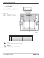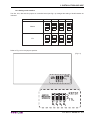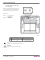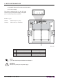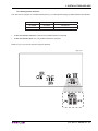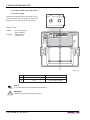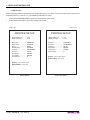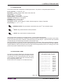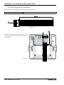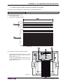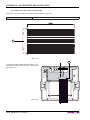
1
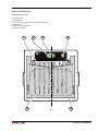
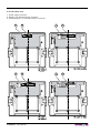
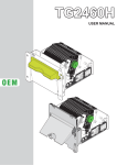
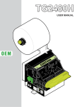
PLUS II
USER MANUAL
OEM
All rights reserved. Total or partial reproduction of this manual in whatever form, whether by printed or electronic means, is forbidden. While guaranteeing that the information contained in it has been carefully checked,
CUSTOM ENGINEERING SPA and other entities utilized in the realization of this manual bear no responsibility
for how the manual is used.
Information regarding any errors found in it or suggestions on how it could be improved are appreciated. Since
products are subject to continuous check and improvement, CUSTOM ENGINEERING SPA reserves the right
to make changes in information contained in this manual without prior notification.
Copyright © 2007 CUSTOM ENGINEERING S.p.a. – Italy
CUSTOM ENGINEERING S.p.A.
Str. Berettine 2 - 43010 Fontevivo (PARMA) - Italy
Tel.: +39 0521-680111 Fax: +39 0521-610701
http: www.custom.it
Customer Service Department:
Tel.: +39 059 88 69 587
Email: [email protected]
PRINTER COMPONENTS
A. PLUS II Front view
1- Paper mouth
2- STATUS Led
3- OPEN key (for paper roll compartment opening)
4- FEED key
5- Paper roll compartment
6- Paper end sensor
1
2
5
3
4
(Fig.1)
6
User Manual
PLUS II
B. PLUS II Rear view
7- Power supply connector
8- RS232 / TTL Serial interface connector
9- CENTRONICS / TTL Parallel interface connector
X
7
X
7
X
8
X
8
PLUSII-S
PLUSII-T
X
7
X
9
X
7
PLUSII-C
PLUSII-P
PLUS II
User Manual
PLUSII-S-0004
X
9
PLUSII-C-0004
TABLE OF CONTENTS
INTRODUCTION
MANUAL CONTENTS ...................................................................................................................................... 1
EXPLANATORY NOTES USED IN THIS MANUAL ......................................................................................... 1
GENERAL SAFETY INFORMATION................................................................................................................ 1
UNPACKING THE PRINTER ........................................................................................................................... 2
GENERAL FEATURES..................................................................................................................................... 3
PRINTER DESCRIPTION ................................................................................................................................ 3
1. INSTALLATION AND USE
1.1 PAPER SPECIFICATIONS ......................................................................................................................1-1
1.1.1 Specifications for LINERLESS paper ..............................................................................................1-1
1.2 CONNECTIONS OF PLUSII-S AND PLUSII-T ........................................................................................1-2
1.2.1 Power supply ...................................................................................................................................1-2
1.2.2 Setting serial interface .....................................................................................................................1-3
1.3 CONNECTIONS OF PLUSII-S-0004 .......................................................................................................1-4
1.3.1 Power supply ...................................................................................................................................1-4
1.3.2 Setting serial interface .....................................................................................................................1-5
1.3.3 Power-On configuration...................................................................................................................1-5
1.4 CONNECTIONS OF PLUSII-C AND PLUSII-P .......................................................................................1-6
1.4.1 Power supply ...................................................................................................................................1-6
1.4.2 Setting parallel interface ..................................................................................................................1-7
1.5 CONNECTIONS OF PLUSII-C-0004.......................................................................................................1-8
1.5.1 Power supply ...................................................................................................................................1-8
1.5.2 Setting parallel interface ..................................................................................................................1-9
1.5.3 Setting JP5 and JP6 jumpers ..........................................................................................................1-9
1.6 SELF-TEST ...........................................................................................................................................1-10
1.7 CONFIGURATION................................................................................................................................. 1-11
1.8 HEXADECIMAL DUMP ......................................................................................................................... 1-11
1.9 MAINTENANCE ....................................................................................................................................1-12
1.9.1 Changing the paper roll .................................................................................................................1-12
1.9.2 Notes about the installation ...........................................................................................................1-13
1.9.3 “EASYLOCK” fixing system ...........................................................................................................1-14
2. INTERFACES
2.1 INTERFACES OF PLUSII-S AND PLUSII-T ............................................................................................2-1
2.1.1 Connection Printer-PC ....................................................................................................................2-2
2.2 INTERFACES OF PLUSII-S-0004 ...........................................................................................................2-4
2.2.1 Connection Printer-PC ....................................................................................................................2-5
2.3 INTERFACES OF PLUSII-C AND PLUSII-P ...........................................................................................2-6
2.3.1 Connection Printer-PC ....................................................................................................................2-7
2.4 INTERFACES OF PLUSII-C-0004...........................................................................................................2-9
2.4.1 Connection Printer-PC ..................................................................................................................2-10
User Manual
PLUS II i
TABLE OF CONTENTS
3. PRINTER FUNCTIONS
3.1 PRINT DIRECTION .................................................................................................................................3-1
3.2 COMMAND DESCRIPTIONS..................................................................................................................3-1
3.2.1 ESC/POS Emulation .......................................................................................................................3-1
4. TECHNICAL SPECIFICATIONS
4.1 TECHNICAL SPECIFICATIONS..............................................................................................................4-1
4.2 DIMENSIONS ..........................................................................................................................................4-3
5. CHARACTER SETS
5.1 CHARACTER SETS ................................................................................................................................5-1
APPENDIX A - ACCESSORIES AND SPARE PARTS
A.1 ACCESSORIES ..................................................................................................................................... A-1
A.1.1 Power supply ................................................................................................................................. A-1
A.1.2 Adaptor frame kit 112X112 ............................................................................................................. A-2
A.1.3 Data and power supply cables kit for PLUSII-S and PLUSII-T ...................................................... A-5
A.1.4 Data serial cable kit for PLUSII-S-0004 ......................................................................................... A-6
A.1.5 Data and power supply cables kit for PLUSII-C and PLUSII-P ...................................................... A-7
A.1.6 Data serial cable kit for PLUSII-C-0004 ......................................................................................... A-8
A.2 SPARE PARTS....................................................................................................................................... A-9
A.2.1 Supplies ......................................................................................................................................... A-9
ii PLUS II
User Manual
INTRODUCTION
MANUAL CONTENTS
In addition to the Introduction which includes a description of the explanatory notes used in the manual, general
safety information, how to unpack the printer and a brief description of the printer including its basic features,
this manual is organized as follows:
Chapter 1:
Chapter 2:
Chapter 3:
Chapter 4:
Chapter 5:
Contains the information required for correct printer installation and its proper use
Contains information on interface specifications
Contains a description of the printer command set
Contains Technical Specifications of the printer
Contains the character sets (fonts) used by the printer
EXPLANATORY NOTES USED IN THIS MANUAL
N.B.
Gives important information or suggestions relative to the use of the printer.
WARNING
Information marked with this symbol must be carefully followed to guard against damaging the
printer.
DANGER
Information marked with this symbol must be carefully followed to guard against operator injury
or damage.
GENERAL SAFETY INFORMATION
•
•
•
•
•
•
•
•
•
•
•
•
•
•
•
Read and keep the instructions which follow.
Follow all warnings and instructions indicated on the printer.
Before cleaning the printer, disconnect the power supply.
Clean the printer with a damp cloth. Do not use liquid or spray products.
Do not operate the printer near water.
Do not use the printer on unstable surfaces that might cause it to fall and be seriously damaged.
During the integration of the printer, we strongly warn to keep an adeguate paper loop outlet underneath
the presenter, in order to allow the receipt being properly printed out.
Only use the printer on hard surfaces and in environments that guarantee proper ventilation.
Make sure the printer is placed in such a way as to avoid damage to its wiring.
Use the type of electrical power supply indicated on the printer label. If in doubt, contact your retailer.
Do not block the ventilation openings.
Do not introduce foreign objects of any kind into the printer as this could cause a short circuit or damage
parts that could jeopardize printer functioning.
Do not spill liquids onto the printer.
Do not carry out technical operations on the printer, with the exception of the scheduled maintenance
procedures specifically indicated in the user manual.
Disconnect the printer from the electricity supply and have it repaired by a specialized technician when:
A.
The feed connector has been damaged.
B.
Liquid has seeped inside the printer.
C.
The printer has been exposed to rain or water.
D.
The printer is not functioning normally despite the fact that all instructions in the users
manual have been followed.
E.
The printer has been dropped and its outer casing damaged.
F.
Printer performance is poor.
G.
The printer is not functioning.
User Manual
PLUS II 1
INTRODUCTION
UNPACKING THE PRINTER
Remove the printer from its carton being careful not to damage the packing material so that it may be re-used
if the printer is to be transported in the future. Make sure that all the components illustrated below are present
and that there are no signs of damage. If there are, contact Customer Service.
1. Box
2. Fixing hooks
3. Paper roll
1
2
3
4
(inside the printer)
4. Printer
(Fig.1)
•
•
•
•
Open the printer packaging
Take out the fixing hooks and remove it from its plastic covering
Take out the printer and remove it from its plastic covering
Keep the box packing materials in the event the printer must be transported/shipped in the future
2 PLUS II
User Manual
INTRODUCTION
GENERAL FEATURES
PLUS II is the new ultra-compact thermal panel printer, paper width 57,5 mm, with “SIXLOAD” easy paper loading
system. PLUS II is performing and versatile, able to satisfy any printing requirements for industrial automation
and garage equipment. In particular, PLUS II is suitable for measurement instrument applications, analysis and
check, weighing systems, gas analyser, anti-theft devices, autoclaves, Pos.
PLUS II is provided with the innovative fixing system “EASYLOCK”: this system allows to fit the printer to any
panel thickness. Moreover PLUS II can be equipped with a plastic surround which makes mechanically compatible with CUSTOM F and P series panel printers.
PLUS II is supplied by 5 Vcc (or 0004 model with extended power supply range 9-48 Vdc) and is available with
serial RS232/TTL interface, parallel Centronics/TTL and paper sensor. It’s equipped with a 203 dpi thermal
printing mechanism, using 57,5 mm-wide paper rolls. It can print 24, 40 or 42 characters per line according to
the selection made at the Setup stage or through a software command. Printer manage LINERLESS paper.
The double hook lock system makes PLUS II safe and reliable.
PRINTER DESCRIPTION
The printer (see Fig.1) has an ABS casing with a front cover (5) which opens to allow access to the paper roll
and print head. The control panel is located on the front and has a FEED key (4) and an OPEN key (3) for
paper roll compartment opening. The OPEN key is made of transparent plastic material so it works also as a
STATUS Led (2).
•
FEED key. When the LINE FEED key is pressed, the printer advances the paper. During power-up, if the
FEED key is held down, the printer enters the SETUP routine and print the SETUP report. The printer will
remain in standby in Hexadecimal dump mode until another key is pressed or characters are received through
the printer communication port; for every 10 characters received it prints hexadecimal values and ASCII
codes (if the characters appear underlined, it means the receive buffer is full); See Hexadecimal Dump.
•
OPEN key. Press the OPEN key to open the paper roll compartment.
•
STATUS Led displays printer hardware status. In case of malfunction, the colour and flash frequency
changing as follows:
(Tab.1)
STATUS
LED
COLOUR
DESCRIPTION
OFF
Printer OFF
ON
Printer ON: no error
RECOVERABLE ERROR
BLINKING
Slow
Paper end
Fast
Heading over temperature
Power supply voltage incorrect
User Manual
PLUS II 3
INTRODUCTION
Blank page
4 PLUS II
User Manual
1. INSTALLATION AND USE
1.1 PAPER SPECIFICATIONS
Printer manage thermal roll (heat-sensitive side on outside of roll) or LINERLESS paper (see paragraph
1.1.1).
1.1.1 Specifications for LINERLESS paper
LINERLESS paper is a thermal paper with a self-adhesive layer without liner (on non heat-ensitive side). For the
better use with the printer the self-adhesive area must comply with the following dimensions (see Fig. 1.1):
HEAT SENSITIVE SIDE
SELF-ADHESIVE
(Fig.1.1)
10
42
5
57±0.5
LINERLESS PAPER SPECIFICATIONS
Self-adhesive
Water based acrylic
Self-adhesive mass
Permanent 16 gr/m2 ±2gr
Total thickness
93 μm ±2 μm
Total weight
96 gr/m2 ±2gr
Recommended temperature
Stick
from +15°C to +40°C
Storage
from +10°C to +40°C
Resistance after stick
from -10°C to +50°C
User Manual
PLUS II 1-1
1. INSTALLATION AND USE
1.2 CONNECTIONS OF PLUSII-S AND PLUSII-T
1.2.1 Power supply
The printer is equipped with a 4 pin JST male
connector (90°) for the power supply. The signals
on the connector pins are as follows::
1
Model no. type:
Header:
Housing:
S4B-PH-K-S 90° (JST)
PHR-4 (JST) or equivalent
(Fig.1.2)
PIN
SIGNAL
DESCRIPTION
1
GND
Ground signal
2
GND
Ground signal
3
+Vin*
Head voltage
4
+Vcc*
Logic supply voltage
NOTE
(*) For the electrical specifications see Chapter 4.
WARNING
Respect the polarity of the power supply.
1-2 PLUS II
User Manual
1. INSTALLATION AND USE
1.2.2 Setting serial interface
The JP4, JP5, JP6 and JP7 jumpers on controller board (see Fig.1.3) manages the setting of serial interface as
indicated:
SERIAL
JP4
JP5
JP6
JP7
RS232
TTL
Refer to Fig.1.3 for the jumpers position.
(Fig.1.3)
RS232
JP5
JP6
JP7
JP4
JUMPERS
SELECTION
INTERFACE
TTL
RS232
JP5
JP6
JP7
JP4
JUMPERS
SELECTION
INTERFACE
TTL
User Manual
PLUS II 1-3
1. INSTALLATION AND USE
1.3 CONNECTIONS OF PLUSII-S-0004
1.3.1 Power supply
The printer is equipped with a 2 pin male connector terminal block (90°) for the power supply. The
signals on the connector pins are as follows:
1
Model no. type:
Header:
Housing:
90° Terminal block
(pitch 5.08mm)
Terminal block
(AWG 20-14)
(Fig.1.4)
PIN
SIGNAL
DESCRIPTION
1
GND
Ground signal
2
+Vin*
Logic supply voltage
NOTE
(*) For the electrical specifications see Chapter 4.
WARNING
Respect the polarity of the power supply.
1-4 PLUS II
User Manual
1. INSTALLATION AND USE
1.3.2 Setting serial interface
See paragraph 1.2.2.
1.3.3 Power-On configuration
The JP8 jumper on controller board (see Fig.1.5) manages the power-on setting function as indicated:
J8
CLOSED
Auto Power-On enabled
OPEN
Auto Power-On disabled
•
If JP8 is closed: The printer switches on when powered up, and it switches off when power is off (default
condition). In this condition the ESC ‘0’ command has not effects.
•
If JP8 is open: When the printer is powered up the low-consumption mode is activated. An impulse of at
least 500 m/sec on pin 6 of the serial RS232 connector must be given to switch on the printer (see par.
2.2.1 and table 2.2). Use ESC “0” command to switch off the printer and bring it back to low-consumption
mode.
Refer to Fig. 1.5 for the JP8 jumper position.
JP8
JUMPER
SELECTION
POWER-ON
CLOSE=AUTO
OPEN=EXTERNAL
(Fig.1.5)
JP8
JUMPER
SELECTION
POWER-ON
CLOSE=AUTO
OPEN=EXTERNAL
RS232
JP5
JP6
JP7
JP4
JUMPERS
SELECTION
INTERFACE
TTL
User Manual
PLUS II 1-5
1. INSTALLATION AND USE
1.4 CONNECTIONS OF PLUSII-C AND PLUSII-P
1.4.1 Power supply
The printer is equipped with a 4 pin JST male
connector (90°) for the power supply. The signals
on the connector pins are as follows:
1
Model no. type:
Header:
Housing:
S4B-PH-K-S 90° (JST)
PHR-4 (JST) or equivalent
(Fig.1.6)
PIN
SIGNAL
DESCRIPTION
1
GND
Ground signal
2
GND
Ground signal
3
+Vin*
Head voltage
4
+Vcc*
Logic supply voltage
NOTE
(*) For the electrical specifications see Chapter 4.
WARNING
Respect the polarity of the power supply.
1-6 PLUS II
User Manual
1. INSTALLATION AND USE
1.4.2 Setting parallel interface
The JP2 and JP1 jumpers on controller board (see Fig.1.7) manages the setting of parallel interface as indicated:
JP1
JP2
PARALLEL INTERFACE SELECTION
CLOSED
CLOSED
Centronics
OPEN
OPEN
TTL
•
If JP1 and JP2 are closed: the Centronics parallel interface is selected.
•
If JP1 and JP2 are open: the TTL parallel interface is selected.
Refer to Fig.1.7 for the JP1 and JP2 jumpers position.
(Fig.1.7)
JUMPERS
SELECTION
+VIN ON
PIN 3-4 J3
JP3
JP4
TTL
CENTRONICS
JP5 JP6
FEED
12
ACK
GND
JUMPERS
SELECTION
INTERFACE
14
LED
JUMPERS
SELECTION
SIGNAL ON
PIN 12-14
JP1
JP2
JUMPERS
SELECTION
INTERFACE
JP1
JP2
User Manual
PLUS II 1-7
1. INSTALLATION AND USE
1.5 CONNECTIONS OF PLUSII-C-0004
1.5.1 Power supply
The printer is equipped with a 2 pin male connector terminal block (90°) for the power supply. The
signals on the connector pins are as follows:
1
Model no. type:
Header:
Housing:
90° Terminal block
(pitch 5.08mm)
Terminal block
(AWG 20-14)
(Fig.1.8)
PIN
SIGNAL
DESCRIPTION
1
GND
Ground signal
2
+Vin*
Logic supply voltage
NOTE
(*) For the electrical specifications see Chapter 4.
WARNING
Respect the polarity of the power supply.
1-8 PLUS II
User Manual
1. INSTALLATION AND USE
1.5.2 Setting parallel interface
See paragraph 1.4.2.
1.5.3 Setting JP5 and JP6 jumpers
The JP5 and JP6 jumpers on controller board (see Fig.1.9) manages the setting for the signals of pin 12 and 14
of parallel interface connector as indicated:
SIGNAL OF PIN 12
JP5
SIGNAL OF PIN 14
FEED
GND
ACK
LED
JP6
Refer to Fig.1.9 for the JP5 and JP6 jumpers position.
JP5 JP6
FEED
GND
12
(Fig.1.9)
14
ACK
LED
JUMPERS
SELECTION
SIGNAL ON
PIN 12-14
JUMPERS
SELECTION
+VIN ON
PIN 3-4 J3
JP3
JP4
TTL
CENTRONICS
JP5 JP6
FEED
12
ACK
GND
JUMPERS
SELECTION
INTERFACE
14
LED
JUMPERS
SELECTION
SIGNAL ON
PIN 12-14
JP1
JP2
User Manual
PLUS II 1-9
1. INSTALLATION AND USE
1.6 SELF-TEST
Printer operating status is indicated in the configuration print-out in which, next to the name of the components
displayed (see Fig.1.10 and 1.11), the following information is given:
•
•
under HEAD TEMPERATURE is given the temperature of the head.
under HEAD VOLTAGE is given the voltage of the head.
(Fig.1.10)
(Fig.1.11)
PRINTER SETUP
HEAD TEMP. [°C]
HEAD VOLT [V]
= 32.5
= 5,00
Baud Rate ................. :
Data Length ............... :
Parity ......................... :
Handshaking ............. :
Autofeed .................... :
Columns .................... :
Print Mode ................. :
Char Mode................. :
Print Density.............. :
38400 bps
8 bits/chr
None
Xon/Xoff
CR Enabled
24 col.
Normal
Normal
0
PRINTER SETUP
HEAD TEMP. [°C]
HEAD VOLT [V]
= 32.5
= 5,00
Interface .................... :
Autofeed .................... :
Columns .................... :
Print Mode ................. :
Char Mode................. :
Print Density.............. :
Centronics
CR Enabled
24 col.
Normal
Normal
0
[PUSH] key to enter setup
[FAST PUSH] key to exit
[PUSH] key to enter setup
[FAST PUSH] key to exit
RS232 Model
1-10 PLUS II
User Manual
Centronics Model
1. INSTALLATION AND USE
1.7 CONFIGURATION
This printer permits the configuration of default parameters. The printer’s configurable parameters are:
Printer Interface (1): Centronics, TTL.
Baud Rate (2): 38400, 19200D, 9600, 4800, 2400,1200, 600.
Data Length (2): 7, 8D bits/chr.
Parity (2): NoneD, Even or Odd.
Handschaking (2): XON/XOFFD o Hardware.
Autofeed: CR disabledD o CR enabled.
Columns: 24 col.D, 40 col. e 42 col.
Print Mode: NormalD o Reverse.
Char Mode: NormalD, Double width (2 x Width), Double height (2 x Height), Expanded.
Print Density: -2, -1, 0D, +1, +2.
GENERAL NOTES: The parameters marked with the symbol D are the default values.
(1)
NOTE: Only parallel interface model parameter.
(2)
NOTE: Only serial interface model parameter.
The settings made are stored in nonvolatile memory and are loaded automatically.
During power-up, if the FEED key is held down, the printer enters the autotest routine and prints out the setup
report. The printer will remain in standby in Hexadecimal dump mode (see par. 1.8) until another key is pressed
or characters are received through the printer communication port.
When the FEED key is pressed, the printer enters parameter configuration. Each time the FEED key is pressed,
the parameter will change and the current value will be printed out. Once the desired value has been attained,
hold the FEED key down for at least a second to pass to the next parameter, and so on. Printing out of a new
printer set up report indicates that set up is complete.
1.8 HEXADECIMAL DUMP
This function is used to display the characters received
from the communications port; after the reception of each
8 characters from the communications port, the printer
prints out both the hexadecimal code received as well as
the corresponding ASCII code.
Shown below is an example of a Hexadecimal Dump:
HEXADECIMAL DUMP
31
39
37
68
73
66
65
6F
6F
77
72
6B
64
73
66
6A
32
30
38
6B
64
73
69
72
75
65
69
6C
66
64
6B
6B
33
31
39
6A
66
64
6F
69
77
72
6F
73
6B
66
F2
6C
34
32
75
73
6B
66
79
75
65
69
75
64
73
6B
6A
68
35
33
69
64
6A
6B
75
77
72
6F
77
66
64
6A
73
36
34
73
68
68
68
77
65
69
75
65
68
66
F2
68
37
35
64
66
73
6A
71
72
6F
77
72
6B
68
73
64
38
36
66
68
64
77
65
69
75
65
68
73
6A
64
66
12345678
90123456
789uisdf
hkjsdhfh
sdfkjhsd
fsdfkhjw
eioyuwqe
oriuweri
ouweriou
weriouwe
riouwerh
klsdfhks
dfksdfhj
sdfkj≥sd
fk≥jshdf
jklh
(Fig.1.12)
User Manual
PLUS II 1-11
1. INSTALLATION AND USE
1.9 MAINTENANCE
1.9.1 Changing the paper roll
To change paper roll, proceed as follows:
1.
2.
3.
4.
5.
Press the OPEN key to open the printer cover as shown (see Fig.1.13).
Place the paper roll making sure it unrolls in the proper direction as shown (see Fig.1.14).
Take out the paper and re-close the cover as shown (see Fig.1.15). The printer cover is locked.
Tear off the exceeding paper using the jagged edge (see Fig.1.16).
The printer is ready.
2
1
(Fig.1.13)
4
3
(Fig.1.15)
1-12 PLUS II
(Fig.1.14)
User Manual
(Fig.1.16)
1. INSTALLATION AND USE
1.9.2 Notes about the installation
Fixing to the panel
Fixing back
Fix the printer in the 3 holes as shown in the
scheme (A) (see Fig.1.17), using M3 tapping
screws (n.3).
Fix the printer in the 3 holes as shown in the
scheme (B) (see Fig.1.18), using 3 screws for
plastic d=3 (6 mm usable length).
(Fig.1.17)
(Fig.1.18)
A
B
NOTE:
The informations provided in this paragraph are corrects for all models.
User Manual
PLUS II 1-13
1. INSTALLATION AND USE
1.9.3 “EASYLOCK” fixing system
This system allows to adapt the printer to every panel thickness and it is not necessary to use other fixing tools.
A FIXING (see Fig.1.19)
• Use only the 2 hooks, provided in the package.
• Place the printer on the panel.
• Insert the 2 fixing hooks in their seat.
• Push the 2 fixing hooks against the panel to lock the printer.
B REMOVING (see Fig.1.20)
• Lift the flap by using a flat screwdriver.
• Take away the hook.
A
B
(Fig.1.19)
(Fig.1.20)
1-14 PLUS II
User Manual
2. INTERFACES
2.1 INTERFACES OF PLUSII-S AND PLUSII-T
The printer with a serial RS232/TTL interface
has a molex 6-pin male connector 53261 series
(90°). Refer to the table below for the connector
pin signals:
1
Model no. type:
Header:
Housing:
Molex 53261 series 6 pin
Molex 51021 series 6 pin (no. 51021-0600))
(Fig.2.1)
(Tab.2.1)
PIN
SIGNAL
IN / OUT
DESCRIPTION
1
DTR
OUT
Data terminal ready
2
TX
OUT
Data transmission
3
RX
IN
Data reception
4
GND
5
FEED
IN
FEED signal
(active at low level)
6
LED
OUT
LED signal (external)
Ground signal
User Manual
PLUS II 2-1
2. INTERFACES
2.1.1 Connection Printer-PC
The diagrams below show a sample connection between printer and Personal Computer using a 6 pin female
Molex 51021 connector by printer side and a 9 pin female connector by a PC side.
DTR
DTR
TX
RX
RX
TX
GND
FEED
GND
LED
1
2
Printer
PC
In the serial protocol, the signals which distinguish the communication are TD, RD, and RTS if the RTS/CTS
protocol has been selected while, if the XON/XOFF protocol has been selected, the signals are TD and RD.
Transmission format
START
BIT
BIT 0
BIT 1
BIT 2
BIT 3
BIT 4
BIT 5
BIT 6
BIT 7(1) PARITY
BIT(2)
STOP
BIT
NOTE:
(1)
Bit 7 is present if only in the printer set-up is enabled 8 bit/char as data length.
(2)
Parity Bit is preset if only in the printer set-up the parity is enabled.
RTS/CTS Protocol
STOP
RD
DATA
START
RTS
2-2 PLUS II
User Manual
STOP
DATA
START
STOP
DATA
START
WAIT
NEXT
START
BIT
2. INTERFACES
XON/XOFF Protocol
STOP
RD
STOP
DATA
WAIT
DATA
START BIT
START BIT
STOP
STOP
TD
$13XOFF
START BIT
$11XON
START BIT
User Manual
PLUS II 2-3
2. INTERFACES
2.2 INTERFACES OF PLUSII-S-0004
The printer with RS232 interface has a 6-pin male
connector AMP-MODU II (90°). Refer to the table
below for the connector pin signals:
1
Model no. type:
Header:
Housing:
AMP-MODU II (no. 280379-2)
AMP-MODU II (no. 280360)
(Fig.2.2)
(Tab.2.2)
PIN
SIGNAL
IN / OUT
DESCRIPTION
1
DTR
OUT
Data terminal ready
2
TX
OUT
Data transmission
3
RX
IN
Data reception
4
GND
5
RESET
IN
Reset signal (active at a low level)
6
POWER-ON
IN
Power-On signal (an impulse of at least
500 m/sec. active at a high level)
2-4 PLUS II
User Manual
Ground signal
2. INTERFACES
2.2.1 Connection Printer-PC
The diagrams below show a sample connection between printer and Personal Computer using a 6 pin female AMP MOUD II connector by printer side and a 9 pin female connector by a PC side.
DTR
RX
TX
TX
RX
GND
GND
DTR
Printer
PC
User Manual
PLUS II 2-5
2. INTERFACES
2.3 INTERFACES OF PLUSII-C AND PLUSII-P
The printer with parallel Centronics/TTL interface has a molex 15-pin male connector 53261
series (90°). Refer to the table below for the
connector pin signals:
1
Model no. type:
Header:
Housing:
Molex 53261 series 15 pin
Molex 51021 series 15 pin
(no. 51021-1500)
(Fig.2.3)
(Tab.2.3)
PIN
SIGNAL
IN /OUT
DESCRIPTION
1
AD0
IN
Data 0
2
AD1
IN
Data 1
3
AD2
IN
Data 2
4
AD3
IN
Data 3
5
AD4
IN
Data 4
6
AD5
IN
Data 5
7
AD6
IN
Data 6
8
AD7
IN
Data 7
9
BUSY
OUT
Peripheral not ready to receive data
10
ERROR
OUT
Error
11
PAPER END
OUT
Paper end
ACK
OUT
Acknowledge
Setting
IN
FEED signal (active at low level)
with JP5 (2)
IN
Strobe
12
13
14
15
FEED
(1)
STROBE
GND
LED
OUT
GND
2-6 PLUS II
Ground signal
Setting
LED signal (external)
with JP6 (2)
Ground signal
User Manual
2. INTERFACES
2.3.1 Connection Printer-PC
The following scheme, represent the connection cable configuration between Molex connector 51021 series
15-pin (female) and a 25-pin connector (female). This cable can be use as wiring between the printer board
and a 25-pin connector (male).
STROBE
JP5
(2)
JP6
(2)
1
2
3
4
5
6
7
8
9
10
11
12
13
14
15
AD0
AD0
AD1
AD1
AD2
AD2
AD3
AD3
AD4
AD4
AD5
AD5
AD6
AD6
AD7
AD7
BUSY
ACK
ERROR
BUSY
PAPER END
PAPER END
(1)
ACK or FEED
STROBE
1
GND or LED
2
ERROR
GND
GND
GND
GND
GND
GND
GND
GND
GND
GND
Printer
1
2
3
4
5
6
7
8
9
10
11
12
13
14
15
16
17
18
19
20
21
21
23
24
25
PC
NOTE
(1)
Signal not available with Centronics interface.
(2)
For JP5 and JP6 settings see paragraph 1.5.3.
User Manual
PLUS II 2-7
2. INTERFACES
For parallel TTL interface printer the communication signals are: 8 bit DATA BUS, STROBE (indicate the data
validity) and BUSY (indicate that the printer is ready to receive data).
Transmission format
VALID DATA
VALID DATA
D0...D7
STROBE
BUSY
Flow diagram
START
ERROR
SI
TIMEOUT
> 1 sec.
NO
BUSY=1
NO
SI
OUT DATA
OUT STROBE=0
SI
TIMEOUT
> 4 sec.
NO
BUSY=0
OUT STROBE=1
RETURN
2-8 PLUS II
User Manual
NO
2. INTERFACES
2.4 INTERFACES OF PLUSII-C-0004
The printer with a parallel Centronics interface,
0004 option, has a molex 15-pin male connector 53261 series (90°). Refer to the table below
for the connector pin signals:
1
Model no. type
Header :
Housing :
Molex 53261 series 15 pin
Molex 51021 series 15 pin
(no. 51021-1500)
(Fig.2.4)
(Tab.2.4)
PIN
SIGNAL
IN /OUT
DESCRIPTION
1
AD0
IN
Data 0
2
AD1
IN
Data 1
3
AD2
IN
Data 2
4
AD3
IN
Data 3
5
AD4
IN
Data 4
6
AD5
IN
Data 5
7
AD6
IN
Data 6
8
AD7
IN
Data 7
9
BUSY
OUT
Peripheral not ready to receive data
10
ERROR
OUT
Error
11
PAPER END
OUT
Paper end
ACK
OUT
Acknowledge
Setting
IN
FEED signal (active at low level)
with JP5 (2)
IN
Strobe
12
13
14
15
FEED
(1)
STROBE
GND
LED
GND
OUT
Ground signal
Setting
LED signal (external)
with JP6 (2)
Ground signal
User Manual
PLUS II 2-9
2. INTERFACES
2.4.1 Connection Printer-PC
The following scheme, represent the connection cable configuration between Molex connector 51021 series
15-pin (female) and a 25-pin connector (female). This cable can be use as wiring between the printer board
and a 25-pin connector (male).
STROBE
JP5
(2)
JP6
(2)
1
2
3
4
5
6
7
8
9
10
11
12
13
14
15
AD0
AD0
AD1
AD1
AD2
AD2
AD3
AD3
AD4
AD4
AD5
AD5
AD6
AD6
AD7
AD7
BUSY
ACK
ERROR
BUSY
PAPER END
PAPER END
(1)
ACK or FEED
STROBE
1
GND or LED
2
ERROR
GND
GND
GND
GND
GND
GND
GND
GND
GND
GND
Printer
PC
NOTE
(1)
Signal not available with Centronics interface.
(2)
For JP5 and JP6 settings see paragraph 1.5.3.
2-10 PLUS II
1
2
3
4
5
6
7
8
9
10
11
12
13
14
15
16
17
18
19
20
21
21
23
24
25
User Manual
3. PRINTER FUNCTIONS
3.1 PRINT DIRECTION
The printer has two printing directions which can be selected by means of the control characters: normal and reverse.
NORMAL MODE
REVERSE MODE
(Fig.3.1)
PAPER
OUTFEED
DIRECTION
3.2 COMMAND DESCRIPTIONS
The table 3.1 shows the commands list, ordered by their hexadecimal value.
LEGEND :
Symbol
$
{}
n, m, t, x, y
Function
indicates the representation of the command hexadecimal value (for example $40 means HEX 40).
indicates an ASCII character not performable.
are optional parameters that can have different values.
3.2.1 ESC/POS Emulation
The following table lists all the commands for function management in ESC/POS Emulation of the printer. The
commands can be transmitted to the printer at any moment, but they will only be carried out when the commands
ahead of them have been executed. The commands are carried out when the circular buffer is free to do so.
COMMAND DESCRIPTION TABLE
(Tab.3.1)
Com. HEX
Com. ASCII
Description
$00
Prints in small characters
$01
Prints in double width
$02
Prints in double height
$03
Expanded printing
$04
Restore small character printing
$0A
Forward feeds on line
(n) $0B
Forward feeds (n) lines
$0D
Print line buffer
$0F
Set CRLF mode
$11
Graphic mode
$1B $23 n
ESC # n
Transmit printer ID
User Manual
PLUS II 3-1
3. PRINTER FUNCTIONS
$1B $30
ESC 0
Switch off the printer
$1B $40
ESC @
Resets the printer
$1B $41 nH nL
ESC A nH nL
Executes (n) dots line feed
$1B $49
ESC I
Selects 24 columns
(dd) $1B $4D
(dd) ESC M
Writes value (dd) in print mode
$1B $4E
ESC N
Set normal mode printing
$1B $51
ESC Q
Enable underlining
$1B $52
ESC R
Set reverse mode printing
$1B $57
ESC W
Print graphic line of 200 dpi
(dd) $1B $61
(dd) ESC a
Selects number of dot spaces
$1B $63
ESC c
Management of bar code printing
$1B $68
ESC h
Selects 42 columns
$1B $69
ESC i
Selects 40 columns
$1B $6D
ESC m
Transmit print mode in serial
$1B $71
ESC q
Disable underlining
$1B $73
ESC s
Transmits next character in serial
$1B $76
ESC v
Transmits printer ID
$1B $FA n1 n2
ESC { } n1 n2
Prints graphic
$1D $24 n
GS $ n
Set absolutes shift into a graphic line
$1D $49 n
GS I n
Transmits the printer ID
$1D $55
GS U
Resets printer parameters to default value
$1D $57 n d1...dn
GS W n d1...dn
Print n byte of a 200 dpi graphic line
ONLY FOR PLUSII-S-0004
NOTE: Commands without specifications are valid for all the models. All that commands which
provide an answer from the printer are not active for the parallel interface models (PLUSII-C,
PLUSII-P and PLUSII-C-0004).
3-2 PLUS II
User Manual
3. PRINTER FUNCTIONS
The following pages provide a more detailed description of each command.
$00
[Name]
[Format]
[Description]
[Notes]
[Default]
[Reference]
[Example]
Small character printing.
ASCII
Hex
00
Decimal
0
The printer prints in small characters (normal)
• The commands from $00 to $09 do not cancel the print buffer
• The commands which modify the direction of the characters are only active at the beginning of the line
Setting in option register by means of front keys
$01, $02, $03, $04, $1B $4D
$01
[Name]
[Format]
[Description]
[Notes]
[Default]
[Reference]
[Example]
Double width printing.
ASCII
Hex
01
Decimal
1
The printer prints in double width format
• The commands from $00 to $09 do not cancel the print buffer.
• The commands which modify the direction of the characters are only active at the beginning of the line.
Setting in option register by means of front keys
$00, $02, $03, $04, $1B $4D
$02
[Name]
[Format]
[Description]
[Notes]
[Default]
[Reference]
[Example]
Double height printing.
ASCII
Hex
02
Decimal
2
The printer prints in double height format
• The commands from $00 to $09 do not cancel the print buffer.
• The commands which modify the direction of the characters are only active at the beginning of the line.
Setting in option register by means of front keys.
$00, $01, $03, $04, $1B $4D
$03
[Name]
[Format]
[Description]
[Notes]
[Default]
[Reference]
[Example]
Expanded printing.
ASCII
Hex
03
Decimal
3
The printer prints in expanded character mode.
• Commands from $00 to $09 do not cancel the print buffer.
• The commands which modify the dimensions of the characters are only active at the
beginning of the line.
Setting in the option register by means of the front keys.
$00, $01, $02, $04, $1B $4D
User Manual
PLUS II 3-3
3. PRINTER FUNCTIONS
$04
[Name]
[Format]
[Description]
[Notes]
[Default]
[Reference]
[Example]
Restore small character printing.
ASCII
Hex
04
Decimal
4
The printer resumes printing with small characters.
• The commands from $00 to $09 do not cancel the print buffer.
• the commands which modify the dimensions of the characters are only active at the
beginning of the line.
Setting in the option register by means of the front keys
$00, $01, $02, $03, $1B $4D
$0A
[Name]
[Format]
[Description]
[Notes]
[Default]
[Reference]
[Example]
Forward feeds one line.
ASCII
Hex
0A
Decimal
10
Forward feeds one line equivalent to a line of print.
• This command brings about the printing of the contents of the line buffer.
• If the line buffer is empty this command executes a line feed of 24 dots (= 3 mm). If the line
buffer contains text the line feed is = (character height + spacing) dots ( default = 4 mm).
$0B
(n) $0B
[Name]
[Format]
[Description]
[Notes]
[Default]
[Reference]
[Example]
Forward feeds (n) lines.
ASCII
Hex
0B
Decimal
11
Carries out the number of line feeds specified in (n).
•The number must be ASCII and between 0 and 9 (when n=0 the command is ignored)
• This command clears the line buffer.
$0A
To forward feed fast, 5 lines at a time:
$35 $0B (or 5 and the command $0B)
$0D
[Name]
[Format]
[Description]
[Notes]
[Default]
[Reference]
[Example]
3-4 PLUS II
Print the line buffer.
ASCII
{}
Hex
0D
Decimal
13
This command prints the line buffer.
• If the line buffer is empty, the command is ignored.
• If the CRLF option is set, this command is ignored and printing can only be ordered
through the command $0A.
$0F
User Manual
3. PRINTER FUNCTIONS
$0F
[Name]
[Format]
[Description]
[Notes]
[Default]
[Reference]
[Example]
Set CRLF mode.
ASCII
Hex
0F
Decimal
15
Inhibits the command $0D maintaining enabled only the command $0A for printing.
• To disable this option, reset the printer.
• This command clears the line buffer.
• On switching on the default value is in the Option Register.
Setting in the option register by means of the front keys.
$0D
$11
[Name]
[Format]
[Description]
[Notes]
Graphic mode.
ASCII
Hex
11
Decimal
17
Enables graphic mode:
a line in 24 column mode corresponds to 144 horizontal dots divided into 24 blocks of 6
dots each; a line in 40 column mode corresponds to 240 horizontal dots divided into 40
blocks of 6 dots each.
To obtain graphic printing, enter the command $11 at the beginning of each line. The
format of the byte in graphic configuration is:
X
R
P6
P5
P4
P3
P2
P1
D7
D6
D5
D4
D3
D2
D1
D0
where:
X
R
P1,..P6
is not used (0 is recommended);
must be fixed at level 1;
are the graphic dot data (1 prints, 0 does not print).
The P6 bit of the string of dots transmitted is printed on the left and the
others follow from left to right (P5, P4, P3, P2, P1) as shown:
1st byte è ►
P6 P5 P4 P3 P2 P1
[Default]
[Reference]
[Example]
2nd byte è ►
P6 P5 P4 P3 P2 P1
3rd byte è ►
P6 P5 P4 P3 P2 P1
To print a line of dots, transmit:
$11, n x $7F (where n is the number of characters per line), $0D.
To print an empty line, transmit:
$11, $40, $0D.
User Manual
PLUS II 3-5
3. PRINTER FUNCTIONS
$1B $23 n
Name]
[Format]
[Range]
[Description]
Transmit printer ID.
ASCII
ESC #
n
Hex
1B
23
n
Decimal
27
73
n
1 ≤ n ≤ 3, 49 ≤ n ≤ 51
Transmits the printer ID specified by n follows:
n
[Notes]
PRINTER ID
SPECIFICATION
1, 49
Printer model ID
$1B
2, 50
Not used
Fixed on $00
3, 51
ROM version ID
Dipends on ROM (4 car)
• This command is executed when the data is processed in the data buffer. Therefore,
there could be a time lag between command reception and data transmission, depending
on data buffer status.
[Default]
[Reference]
[Example]
$1B $30 (only for PLUSII-S-0004)
[Name]
[Format]
[Description]
[Notes]
[Default]
[Reference]
[Example]
Switch-off the printer.
ASCII
ESC 0
Hex
1B
30
Decimal
27
48
Switch off the printer and bring it back to low-consumption mode if was disabled the Auto
POWER-ON function (see paragraph 1.3.3).
• This command is executed only when the JP8 jumper is open.
$1B $40
[Name]
[Format]
[Description]
[Notes]
Resets the printer.
ASCII
ESC @
Hex
1B
40
Decimal
27
64
Cancels all the data in the print buffer and resets the printer mode, restoring the mode
which was enabled at the moment of switching on.
• Same as hardware reset.
• After the command has been transmitted, 1.5 seconds elapse before the printer is enabled.
[Default]
[Reference]
[Example]
3-6 PLUS II
User Manual
3. PRINTER FUNCTIONS
$1B $41 nH nL
[Name]
[Format]
[Range]
[Description]
[Notes]
[Default]
[Reference]
[Example]
Executes (n) dots line feed.
ASCII
ESC A
nH
nL
Hex
1B
41
nH
nL
Decimal
27
65
nH
nL
0 ≤ nH, nL ≤ 255
Executes (N) dots line feed where N = 256 x nH + nL.
• 1 mm = 8 dot line.
• The maximum paper line feed value is about 1 m.
To forward feed 40mm send this sequence:
$1B $41 $01 $40 (the ESC A command with 40mm x 8dot)
$1B $49
[Name]
[Format]
[Description]
[Notes]
[Default]
[Reference]
[Example]
Selects 24 columns.
ASCII
ESC I
Hex
1B
49
Decimal
27
73
On receiving this command, the printer enters 24-column per line printing mode.
$1B $69, $1B $68
(dd) $1B $4D
[Name]
[Format]
[Range]
[Description]
Writes the value (dd) in the print mode.
ASCII
dH
dL
ESC M
Hex
dH
dL
1B
4D
Decimal
dH
dL
27
77
dH = 48
48 ≤ dL ≤ 51
Sets the print mode default parameters. ASCII characters (dd) identify an hexadecimal
byte as follow:
$00
$01
$02
$03
[Notes]
[Default]
[Reference]
[Example]
small character printing
double width printing
double height printing
expanded printing
Setting in option register by means of front keys.
$00, $02, $03, $04, $1B $6D
For double height printing, transmit:
$30 $32 $1B $4D
$1B $4E
[Name]
[Format]
[Description]
Set normal mode printing.
ASCII
ESC N
Hex
1B
4E
Decimal
27
78
Select normal mode printing:the receipt feeds out of the printer with the printing upside
down running from right to left.
User Manual
PLUS II 3-7
3. PRINTER FUNCTIONS
[Notes]
[Default]
[Reference]
[Example]
Setting in option register by means of front keys
$1B $52
$1B $51
[Name]
[Format]
[Description]
[Note]
[Default]
[Reference]
[Example]
Enable underlined printing.
ASCII
ESC Q
Hex
1B
51
Decimal
27
81
After this command has been received, the characters are printed underlined.
$1B $71
$1B $52
[Name]
[Format]
[Description]
[Notes]
[Default]
[Reference]
[Example]
Set reverse mode printing.
ASCII
ESC R
Hex
1B
52
Decimal
27
82
Selects printing in reverse mode: the receipt feeds out of the printer with the printing in
normal mode running from left to right.
Setting in option register by means of front keys.
$1B $4E
$1B $57
[Name]
[Format]
[Description]
Prints a graphic line at 203 dpi.
ASCII
ESC W
Hex
1B
57
Decimal
27
87
After receiving this command, the printer waits for 48 bytes which correspond to an entire
graphic line. In fact, 48 bytes of 8 bits each correspond to 384 dots per line.
[Notes]
[Defaul]
[Reference]
[Example]
(dd) $1B $61
[Name]
[Format]
[Description]
[Notes]
[Default]
[Reference]
[Example]
3-8 PLUS II
Selects the number of dot spaces.
ASCII
(dd)
ESC a
Hex
(dd)
1B
61
Decimal
(dd)
27
97
By using (dd) parameters it’s possible to select the dot line number between one print
line and another.
• (dd) are two ASCII characters (selected between ‘0’, ‘1’ ... ‘9’, ‘A’, ‘B’ ... ‘F’) which identifies number from 0 to 127 in hexadecimal form and corresponds to the number of dot
lines between one print line and another. The acceptable range is from $00 to $7FH.
0
User Manual
3. PRINTER FUNCTIONS
$1B $63
[Name]
[Format]
[Description]
Management of bar code printing.
ASCII
ESC c
[code] [height] [position] [options] [length] [data]
Hex
1B
63
Decimal
27
99
This command executes a barcode printing with the following settings:
[ASCII code] Type of bar code:
I
Interleaved 2/5
C
Code 39
B
CodaBar
e
EAN8
E
EAN13
[height]
Number of dot lines in 1/8 mm. units.
[position]
Left hand margin, expressed in 1/8 mm. units
[options]
Specify the bar code options trough a byte. In the following tables are listed
all the possible values of single bit inside of byte:
BIT 0
FUNCTION
0
Check digit is not printed
1
Check digit is printed
BIT 1
FUNCTION
-
Check digit
DESCRIPTION
Not used
-
BIT 3
BIT 2
0
0
None
0
1
Above
1
0
Below
1
1
Above & below
BIT 5
BIT 4
FUNCTION
0
0
Normal
1
Double
1
0
Triple
1
1
Not used
BIT 6
-
DESCRIPTION
HRI Position
FUNCTION
0
DESCRIPTION
Barcode
width
FUNCTION
DESCRIPTION
Not used
BIT 7
-
DESCRIPTION
FUNCTION
DESCRIPTION
Not used
-
[length]
Specify the characters number to print trough a byte; in following are listed
the maximum lenghts allowed:
Interleaved 2/5
= 12 characters
Code 39
= 10 characters
CodaBar
= 10 characters
EAN8
= 7 characters
EAN13
= 12 characters
[data]
Specify the characters to print expressed in ASCII.
User Manual
PLUS II 3-9
3. PRINTER FUNCTIONS
[Notes]
[Default]
[Reference]
[Example]
• For EAN8 and EAN13 barcodes the check digit is automatic.
• When CODE 39 barcode is used with triple width function, if 6 characters + check digit
are sent the print limits are exceeded, so the barcode can’t be printed.
In the following example is indicated the command sequence to print a barcode:
$1B, ‘N’, $1B, ‘c’, ‘C’, $50, $3C, $14, $04, ‘PLUS’
where:
$1B, ‘N’
$1B, ‘c’,
‘C’,
$50,
$3C,
$14,
$04,
‘PLUS’
(sets the printing in normal mode)
(bar code printing command)
(barcode type = Code 39)
(barcode heigth = 10 mm)
(starting position = 7,5 mm)
(HRI printing below, barcode width double)
(characters number to print)
(characters to print)
$1B $68
[Name]
[Format]
[Description]
[Notes]
[Default]
[Reference]
[Example]
Selects 42 columns.
ASCII
ESC h
Hex
1B
68
Decimal
27
104
On receiving this command, the printer enters 42-column per line printing mode.
$1B $49, $1B $69
$1B $69
[Name]
[Format]
[Description]
[Notes]
[Default]
[Reference]
[Example]
3-10 PLUS II
Selects 40 columns.
ASCII
ESC i
Hex
1B
69
Decimal
27
105
On receiving this command, the printer enters 40-column per line printing mode.
$1B $49, $1B $68
User Manual
3. PRINTER FUNCTIONS
$1B $6D
[Name]
[Format]
[Description]
[Notes]
[Default]
[Reference]
[Example]
Transmits the print mode in serial.
ASCII
ESC m
Hex
1B
6D
Decimal
27
109
Transmits the print mode configuration on the serial port.
• If the printer is using the parallel protocol, nothing will be transmitted.
• If the print mode setting is $04 the printer answer $30 $30 (normal character).
Setting in the option register by means of the front keys.
The response is on two bytes. For example if you receive:
$30, $32
it means that printing is in double height mode
$1B $71
[Name]
[Format]
[Description]
[Notes]
[Default]
[Reference]
[Example]
Disable underlined printing.
ASCII
ESC q
Hex
1B
71
Decimal
27
113
Disable underlined printing
$1B $51
$1B $73
[Name]
[Format]
[Description]
[Notes]
[Default]
[Reference]
[Example]
Transmits the next character in serial.
ASCII
ESC s
Hex
1B
73
Decimal
27
115
Transmits the next character it receives on the serial port.
If you transmit:
$1B $73 $41
the last character, A ($41), will not be printed but immediately transmitted on the serial
line.
User Manual
PLUS II 3-11
3. PRINTER FUNCTIONS
$1B $76
[Name]
[Format]
[Description]
[Notes]
Transmit paper sensor status.
ASCII
ESC v
Hex
1B
76
Decimal
27
118
When this command is received, transmit the current status of the paper sensor.
• This command is executed immediately, even when the data buffer is full (Busy).
The status to be transmitted is shown in the table below:
Bit
0,1
2,3
4
5
6
7
Off/On
Hex
Decimal
Off
00
0
Cover close, paper present.
Function
On
03
3
Cover open or paper sensor not working.
Off
00
0
Paper-end sensor: paper present.
On
0C
12
Paper-end sensor: paper not present.
Off
00
0
Not used. Fixed to Off.
Off
00
0
Head temperature correct.
On
20
32
Head temperature error.
Off
00
0
Supply voltage correct.
On
40
64
Supply voltage error.
Off
00
0
Not used. Fixed to Off.
[Default]
[Reference]
[Example]
$1B $FA n1 n2
[Name]
[Format]
[Range]
[Description]
[Notes]
[Default]
[Reference]
[Example]
Print graphic bank ( 384 x 85 dots).
ASCII
ESC {}
n1
n2
Hex
1B
FA
n1
n2
Decimal
27
250
n1
n2
0 ≤ n1, n2 ≤ 255
Prints the graphics bank from flash.
n1 specifies the starting dot line (1 ÷ 85).
n2 specifies the number of lines to print.
• If n1 + n2 > 85 the printer only prints 85 - n1 + 1 dotlines.
To print the graphic bank from dotline 10 to dotline 40, send:
$1B $FA $0A $1E
$1D $24 n
[Name]
[Format]
[Range]
[Description]
[Notes]
[Default]
[Reference]
[Example]
3-12 PLUS II
Set absolute shift into a graphic line.
ASCII
GS
$
n
Hex
1D
24
n
Decimal
29
36
n
0 ≤ n ≤ 47
Set the print beginning position into a graphic line based on the current value of n that
indicate the byte number of shift from left margin.
• Settings outside the specified printable area are ignored.
User Manual
3. PRINTER FUNCTIONS
$1D $49 n
[Name]
[Format]
[Range]
[Description]
Transmit printer ID.
ASCII
GS
I
n
Hex
1D
49
n
Decimal
29
73
n
1 ≤ n ≤ 3, 49 ≤ n ≤ 51
Transmits the printer ID specified by n follows:
n
[Notes]
PRINTER ID
SPECIFICATION
1, 49
Printer model ID
$1B
2, 50
Not used
Fixed on $00
3, 51
ROM version ID
Dipends on ROM (4 car)
• This command is executed when the data is processed in the data buffer. Therefore,
there could be a time lag between command reception and data transmission, depending
on data buffer status.
[Default]
[Reference]
[Example]
$1D $55
[Name]
[Format]
[Description]
[Notes]
[Default]
[Reference]
[Example]
Resets the printer parameters to default.
ASCII
GS
U
Hex
1D
55
Decimal
29
85
Resets the printer parameters to the default configuration.
• After executing this command the printer is initialized.
$1D $57 n d1...dn
[Name]
[Format]
[Range]
[Description]
[Notes]
[Default]
[Reference]
[Example]
Prints n byte of a 200 dpi graphic line.
ASCII
GS
W
n
d1...dn
Hex
1D
57
n
d1...dn
Decimal
29
87
n
d1...dn
1 ≤ n ≤ 48
0 ≤ d1…dn ≤ 255
Print n byte of a 200 dpi graphic line where:
•n
specifies the number of byte to print;
• d1...dn specify the bytes to print.
• If the bit image data input exceeds the number of dots to be printed on a line, the excess
data are processed as printable characters.
• d indicates the bit image data. Set a corresponding bit to 1 to print a dot, or to 0 to not
print the dot.
• This command is not affected by the emphasized, double-strike, underline (etc.) print
modes and the upside-down mode.
For printing 12 bytes the command sequence is:
$1D $57 $0C $FF $00 $FF $00 $FF $00 $FF $00 $FF $00 $FF $00
User Manual
PLUS II 3-13
3. PRINTER FUNCTIONS
Blank page
3-14 PLUS II
User Manual
4. TECHNICAL SPECIFICATIONS
4.1 TECHNICAL SPECIFICATIONS
Table 4.1 gives the main technical specifications for the printer.
Available interfaces
Baud rate
(Tab.4.1)
Serial RS232 / TTL
Parallel Centronics / TTL
From 600 to 38400 bps
-
Head temperature, paper end
OPTIONAL: Cover open sensor
Sensors
Printing driver
WindowTM 2K, XP
Receive buffer
128 Kbytes
Flash memory
32 Mbytes
Emulation
CUSTOM
PRINTER SPECIFICATIONS
Print method
Thermal, fixed head
Resolution
203 DPI (8 dot/mm)
Printing mode
Straight, 180°
Printing format
Normal, width from 1 to 2, bold, reverse, underlined
Character fonts
ASCII standard, International
Graphics memory
1 Logo (384 x 85 dots)
Number of columns
24
40
16 x 24
8 x 24
Lines / sec.
13
13
Chars / sec.
307
512
Characters (L x H mm)
2x3
1x3
Character matrix
Printing speed
PAPER SPECIFICATIONS
Thermal rolls (heat-sensitive side on outside of roll)
LINERLESS paper (see paragraph 1.1.1)
Type of paper
Paper width
57 mm ±0.5 mm
from 55 g/m2 to 70 g/m2
Recommended types of paper
Internal roll core diameter
13 mm
External roll diameter
max. Ø50 mm
Core type
Cardboard or plastic
ELECTRICAL SPECIFICATIONS
Power Supply
Vcc
Vin
3.5 ÷ 8 V (Range max.)
3.5 ÷ 8 V (Range max.)
-
9 ÷ 48 V (Range max.)
PLUS II-C (2), PLUS II-P (2)
5 ± 5%
3.5 ÷ 8 V (Range max.)
PLUS II-C (2), PLUS II-P (2)
-
9 ÷ 48 V (Range max.)
(2)
PLUS II-S , PLUS II-T
PLUS II-S-0004
(2)
(2)
Absorptions (5V)
Medium
(50% Dot ON)
Stand by
0.2 A (Vcc)
3.3 A (Vin)
0.1 A
User Manual
PLUS II 4-1
4. TECHNICAL SPECIFICATIONS
Absorptions (9 ÷ 48 V)
3 A (9V)
0.7 A (48V)
Medium
(50% Dot ON)
Stand by
0.1 A
Absorptions (3.5 ÷ 8 V)
3.3 A (3.5V)
2.5 A (8V)
Medium
(50% Dot ON)
Stand by
0.1 A
ENVIRONMENTAL CONDITIONS
Operating temperature
Relative humidity
Storage temperature /
Humidity
0-50°C
10-85% Rh
-20 °C – 70 °C / 10% - 90% Rh
Length [mm] = 90 max.
Dimensions
Width [mm] = 57 max.
Height [mm] = 85.5 max.
141 (1)
Weight [gr]
NOTE
(1)
Referred without paper roll.
(2)
Codes description:
PLUS II-S
Serial RS232
PLUS II-T
Serial TTL
PLUS II-S-0004
RS232 Extended range
PLUS II-C
Parallel Centronics
PLUS II-P
Parallel TTL
PLUS II-C-0004
Parallel Centronics Extended range
4-2 PLUS II
User Manual
4. TECHNICAL SPECIFICATIONS
4.2 DIMENSIONS
Versions:
PLUS II-S
PLUS II-T
Versions:
PLUS II-C
PLUS II-P
PLUS II-C-0004
PLUS II-S-0004
N°3 SCREWS ø3
FOR PLASTIC
14.6
24.1
13.1
50
10.4
18.4
10.1
N°
3
35
70.5
TH
RE
AD
S
(M
3)
(Fig.4.1)
3 Max (Panel thickness)
11
81
81.5
85
89
85.5
MOUNTING SEAT IN THE PANNEL
82±0,5
43,2
45
57
1,8
111
90°
82±0,5
User Manual
PLUS II 4-3
4. TECHNICAL SPECIFICATIONS
Blank page
4-4 PLUS II
User Manual
5. CHARACTERS SET
5.1 CHARACTER SETS
The printer has 2 fonts each width 224 characters (Font 1 and Font 2). Shown below in figure 5.1 is an example
of font1.
Font 1
(Fig.5.1)
User Manual
PLUS II 5-1
5. CHARACTERS SET
Blank page
5-2 PLUS II
User Manual
APPENDIX A - ACCESSORIES AND SPARE PARTS
A.1 ACCESSORIES
A.1.1 Power supply
The figure below illustrates the power supply provided by Custom to be used for printer operation of PLUSII-S
, PLUSII-T, PLUSII-C and PLUSII-P models.
14.5
2-M3
3
65
60-460-175-1.2
60-465-175-1.2
11
93
28±1
11
55
13
25.4
16.4
4-M3
(BOTTOM)
-V
18
50.8±1
+V
25.4
PE
16.4
N
L
38.5
40.5
79±1
(Fig.A.1)
1. TERMINAL BLOCK: 5P, PITCH 7.62 mm WITH PC COVER
2. UNIT: mm
PPSPS-025-05
Switching power supply 5V 25W
Input specifications
Input voltage
AC: 85V ÷ 264V
Current
DC: 120V ÷ 375V
0.8A max at 100V AC input
Input frequency
47Hz ÷ 63Hz
Output specifications
Output voltage
5V
Output current
5.0A
Efficiency
72%
Environmental conditions
Operating temperature
-25°C ÷ 70°C
Humidity
Storage temperature / Humidity
20% ÷ 85%
-25°C ÷ 75°C / 10% ÷ 95% (w/o condensation)
Protection devices: Shortcircuit, overload and overvoltage.
User Manual
PLUS II A-1
APPENDIX A - ACCESSORIES AND SPARE PARTS
A.1.2 Adaptor frame kit 112X112
The printer has an adaptor frame which makes it mechanically compatible with CUSTOM F and P series panel
printers (see Fig. A.2).
PCXSP-PLUS-2
Grey adaptor frame with hooks
PCXSP-PLUS-3
Black adaptor frame with hooks
The kit is composed of:
1. N°2 Fixing hooks
2. Adaptor frame (1)
1
2
(Fig.A.2)
NOTE:
(1)
Pay attention that the external frame, the cover and the printer frame are made from polypropylene,
so it’s better to keep away from: Ammonia, Methanol, Acetone, Washing-up liquid, Benzol, Dishwasher
liquid, Hydrocarbon, Dichloromethane, Perchloretylene, Ethylene, Trichlorethylene, Toluene.
A-2 PLUS II
User Manual
APPENDIX A - ACCESSORIES AND SPARE PARTS
Assembling instructions
•
•
•
•
Fit the printer (A) into the adaptor frame (B), making sure that the side of the printer with carter gears (C)
is aligned with the hooking slide of the frame with the smoothed corner (D), not the side with two hooks
(see Fig. A.3).
Fix the printer to the frame using the 2 hooks (E) included with the printer (see Fig. A.3)
The printer/frame unit is assembled.
Fit the printer/frame unit (F) into the panel (G) and fix it using the 2 hooks (H), included in the assembling kit (see Fig. A.4).
1
(Fig.A.3)
E
E
D
B
C
A
2
H
H
G
F
(Fig.A.4)
User Manual
PLUS II A-3
APPENDIX A - ACCESSORIES AND SPARE PARTS
Printer dimensions assembled with the frame
N°3 SCREWS ø3
FOR PLASTIC
3
N°
113±0.5
50
113±0.5
MOUNTING SEAT IN THE PANNEL
S
AD
RE
TH
35
3)
(M
10J Max (Panel thickness)
39.5
46.5 MAX
17,4
111
90°
26.3
112
CLIPS FOR
PANEL FIXING
112
119
123.2
(Fig.A.5)
119
A-4 PLUS II
User Manual
APPENDIX A - ACCESSORIES AND SPARE PARTS
A.1.3 Data and power supply cables kit for PLUSII-S and PLUSII-T
The printer can be supplied with a data and power supply cables STARTER KIT.
PCSKMINIPLUS-S
Starter Kit cables for serial MINIPLUS
The kit includes (see Fig. A.6):
1. Power supply cable.
2. Data cable for serial interface.
500mm
1
2
(Fig.A.6)
1
2
To the cable connections proceed as follow:
•
•
Connect the power supply cable (1) to the
power supply connector in the rear of the
printer (see Fig. A.7).
Connect the data serial interface cable (2)
to the interface connector in the rear of the
printer (see Fig. A.7)
(Fig.A.7)
User Manual
PLUS II A-5
APPENDIX A - ACCESSORIES AND SPARE PARTS
A.1.4 Data serial cable kit for PLUSII-S-0004
The printer can be supplied with a data serial cable (see Fig. A.8).
PCSKPLUS-0004
Starter Kit for PCPLUS-S-0004
500mm
X
1
(Fig.A.8)
1
Connect the data serial interface cable (1) to
the interface connector in the rear of the printer
(see Fig. A.9).
(Fig.A.9)
A-6 PLUS II
User Manual
APPENDIX A - ACCESSORIES AND SPARE PARTS
A.1.5 Data and power supply cables kit for PLUSII-C and PLUSII-P
The printer can be supplied with a data and power supply cable starter kit.
PCSKPLUS-C
Starter Kit cables for PCPLUS-C and PCPLUS-P
The kit includes (see Fig. A.10):
1. Power supply cable.
2. Data cable for parallel interface.
500mm
1
2
(Fig.A.10)
1
2
To the cable connections proceed as follow:
•
•
Connect the power supply cable (1) to the
power supply connector in the rear of the
printer (see Fig. A.11).
Connect the data parallel interface cable (2)
to the interface connector in the rear of the
printer (see Fig. A.11)
(Fig.A.11)
User Manual
PLUS II A-7
APPENDIX A - ACCESSORIES AND SPARE PARTS
A.1.6 Data serial cable kit for PLUSII-C-0004
The printer can be supplied with a data parallel cable (see Fig. A.12).
PCSKPLUS-C-0004
Starter Kit for PCPLUS-C-0004
500mm
1
(Fig.A.12)
1
Connect the data parallel interface cable (1) to
the interface connector in the rear of the printer
(see Fig. A.13).
(Fig.A.13)
A-8 PLUS II
User Manual
APPENDIX A - ACCESSORIES AND SPARE PARTS
A.2 SPARE PARTS
A.2.1 Supplies
RCT57X50
Thermal paper roll 57mm d=50
Quantity recommended per n° machines purchased
N° machines
<10
<50
<100
>100
5
30
60
90
<10
<50
<100
>100
5
30
60
90
Quantities recommended
RCT57X50-18MM-LL
Linerless paper roll L=57 Di=18 De=50
Quantity recommended per n° machines purchased
N° machines
Quantities recommended
User Manual
PLUS II A-9
Rev. 1.00
Part Number : DOME-PLUSII
CUSTOM ENGINEERING SPA
World Headquarters
Via Berettine, 2 - 43100 Fontevivo
Tel. +39 0521 680111 - Fax +39 0521 610701
[email protected] - www.custom.biz
All rigths reserved
www.custom.biz