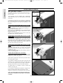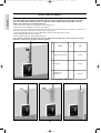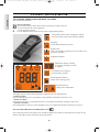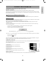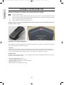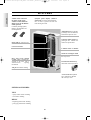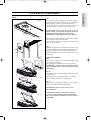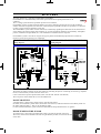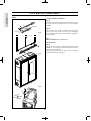
1
sk foglio intestazione.qxp 16/09/2011 15.55 Pagina 1 I Installazione, uso e manutenzione - 3 versioni A/B/C p. 2 / 2 / 2 UK Installation, use and maintenance - 3 versions A/B/C p. 28 / 28 / 30 F Installation, usage et maintenance - 3 versions A/B/C p. 54 / 54 / 58 E Instalación, uso y mantenimiento - 3 versiones A/B/C p. 80 / 80 / 86 D Installations-, Betriebs- und Wartungsanleitung A/B/C p. 106 / 106 / 112 NL Installatie, gebruik en onderhoud - 3 versies A/B/C p. 132 / 132 / 140 3 versionen TINY KELLY A I Valida per i seguenti numeri di garanzia: UK Valid for the following certificate numbers: F Valide pour les numéros de garantie suivants: E Válida para los siguientes números de garantía: D Gültig für folgende Garantienummern: NL Geldig voor de volgende garantie nummers: 384651 - 3884900 / 3888301 - 3888450 / 3890201 - 3890400 / 3890701 - 3890800 / da 3891151 - 3891200 sk tecnica Multilingua TINY_KELLY cod 665980 _definitiva x stampa.qxp 24/06/2011 9.56 Pagina 29 ENGLISH Dear Sir/Madam Congratulations and thank you for choosing our product. Please read this document carefully before you use this product in order to obtain the best performance in complete safety. For further details or assistance, please contact the DEALER where you purchased the product or visit the TECHNICAL ASSISTANCE CENTRES page on our website www.edilkamin.com. NOTE - After you remove the packaging, please inspect the unit for any damage or missing parts (cladding, remote control only Tiny, connecting sleeves, warranty booklet, glove, technical data sheet, spatula, desiccant). In case of anomalies please contact the dealer where you purchased the product immediately. You will need to present a copy of the warranty booklet and valid proof of purchase. - Commissioning/ testing Commissioning and testing must be performed by an authorized Edilkamin Technical Assistance Centre. Failure to do so will void the warranty. Commissioning, as specified in standard UNI 10683 Rev. 2005 (section "3.2") consists in a series inspections to be performed with the insert installed in order to ascertain the correct operation of the system and its compliance to applicable regulations. To locate the Technical Assistance Centre closest to you, please ask your local dealer, call our toll-free number, or visit our website www.edilkamin.com. - Incorrect installation, incorrect maintenance, or improper use of the product, shall relieve the manufacturer from any damage resulting from the use of this product. - the proof of purchase tag, necessary for identifying the insert, is located: - on the top of the package - in the warranty booklet found inside the firebox - on the ID plate affixed to the back side of the unit; This documentation must be saved for identification together with the valid proof of purchase receipt. The data contained therein must be reported when requesting information and made available should servicing be required; - All images are for illustration purposes only; actual products may vary. DECLARATION OF CONFORMITY The undersigned EDILKAMIN S.p.a. with head office headquarters at Via Vincenzo Monti 47 - 20123 Milan - Italy - VAT IT00192220192 Declares under its own responsability as follows: The wood pellet stoves specified below is in accordance with the 89/106/EEC (Construction Products) WOOD PELLET STOVES, trademark EDILKAMIN, called TINY - KELLY Year of manufacture: Serial number: Ref. Data nameplate Ref. Data nameplate The compliance with the 89/106/EEC directive is besides determined by the compliance with the European standard: UNI EN 14785:2006 the wood pellet stove TINY - KELLY is in compliance with the requirements of the European directives: 2006/95/EEC - Low voltage directive 2004/108/EEC - Electromagnetic compatibility directive EDILKAMIN S.p.a. will decline all responsability of malfunctioning or damage to the equipment in case of unauthorized substitution, assembly or modifications of any sort on the said equipment on the part of non-EDILKAMIN personnel. 28 24/06/2011 9.56 Pagina 30 PRINCIPLE OF OPERATION SAFETY INFORMATION TINY - KELLY stoves heat the air using wood pellets as fuel, with electronically controlled combustion. Hereunder is the explanation of its functions (the letters refer to figure 1). The fuel (pellets) is provided by the storage hopper (A) and, to the combustion chamber (D) by means of a feed screw (B), which is driven by a gear motor (C). The pellets are ignited by the air that is heated by an electrical resistance (E) and drawn into the combustion chamber by a smoke extractor (F). The fumes produced during the combustion process are extracted from the hearth by the same centrifugal fan (F), and expelled through the outlet (G) located on the lower part of the stove. The stoves are designed to allow warm air to be channelled, to heat an adjacent room. Three outlets are set up to channel warm air (on the rear, side and top). Use the most suitable one (hence the caps will have to be used to close off the other outlets) connecting it with the specifically-designed optional KIT 8. The hearth is lined with cast iron, closed in the front by two overlapping doors. - a ceramic glass external door with a "button-action" opening mechanism (use the special thermal glove to open the stove). - an inner door made from ceramic glass which is in direct contact with the fire. The amount of fuel, smoke extraction, and air - fuel supply are all controlled by the softwareequipped circuit board, with the aim of obtaining highly efficient fuel consumption and low emissions. All phases of operation can be managed via radio remote control (provided with the Tiny model). Whereas the Kelly model has a synoptic panel (M) installed on the lefthand side, which allows you to control and view all phases of operation. An optional remote control to manage the main functions is available for the Kelly model. The stove is equipped with a serial port to connect an optional cable (TINY cod. 621240 - KELLY cod. 620550) to be connected to devices that allow remote ignition (e.g. remote telephone, local thermostat). The TINY - KELLY stoves are designed to provide heating, by automatically burning pellets in the hearth, in the room where they are installed, as well as radiate heat and circulate air coming out of the front grille, and in the adjacent room by circulating channelled air from the rear, right side or top outlet. fig. 1 • The only risks that may derive from using the stove pertain to non-compliance with installation instructions, direct contact with live electrical parts (internal), contact with the fire or hot parts (glass, pipes, hot air output), or foreign substances being put in the stove. • Only use wood pellets with 6 mm diameter as fuel. • Should components fail, the stoves are equipped with safety devices that guarantee automatic shutdown. These are activated without any intervention required. • In order to function correctly, the stove must be installed in accordance with the instructions given herein and the door must not be opened during operation: combustion is fully automatic and requires no intervention. • Under no circumstances should any foreign substances be entered into the hearth or hopper. • Do not use flammable products to clean the smoke channel (the flue section connecting the stove smoke outlet to the chimney flue). • Hearth and hopper components must only be cleaned with a vacuum cleaner. • The glass can be cleaned when COLD with a suitable product (e.g. GlassKamin Edilkamin) and a cloth. • Do not clean when hot. • Ensure that the stoves are installed and ignited by a qualified Edilkamin DEALER, in accordance with the instructions given herein. • When the stove is in operation, the exhaust pipes and door become very hot (do not touch without wearing the thermal glove). • Do not place anything, which is not heat resistant near the stove. • NEVER use liquid fuel to ignite the stove or rekindle the embers. M • Do not obstruct the ventilation apertures in the room where the stove is installed, nor the air inlets of the stove itself. A • Do not wet the stove and do not go near electrical parts with wet hands. D B E C • Do not use reducers on the smoke exhaust pipes. • The stove must be installed in a room that is suitable for fire prevention and equipped with all that is required (power and air supply and outlets) for the stove to function correctly and safely. F • Should ignition fail, DO NOT re-ignite until you have emptied the combustion chamber. G •ATTENTION: THE PELLET EMPTIED FROM THE COMBUSTION CHAMBER MUST NOT BE DEPOSITED INSIDE THE HOPPER. 29 ENGLISH sk tecnica Multilingua TINY_KELLY cod 665980 _definitiva x stampa.qxp sk tecnica Multilingua TINY_KELLY cod 665980 _definitiva x stampa.qxp 24/06/2011 9.56 Pagina 31 ENGLISH FEATURES • Radio remote control for the TINY model (series) • Remote control without no display screen for the KELLY model (optional) to remotely manage ignition, turning it off, automatic and manual operation. Synoptic panel display (KELLY model only) to set the desired temperature as well as ignition and turn off times during the week. Adjustment lever, to manually manage warm air diffusion, and heat the adjacent room. Capacious pellet hopper for prolonged use without the need for frequent refills. Front grille for warm air to be emitted into the room. Cast iron structure 1 Ø10cm outlet to channel warm air Warm air exchangers which are easy to clean thanks to the easy access Door with screen printed ceramic glass, automatically cleaned at all times, with a "button-action" opening mechanism. Powerful and silent fan for maximum comfort (400 m3/h) Ash pan to facilitate cleaning the hearth. "AUTO-CLEAN" system for a combustion chamber that is always clean. EXTERNAL FINISHES: TINY - opaque white ceramic cladding - red ceramic cladding KELLY - burgundy-painted steel cladding - pearl grey-painted steel cladding 30 sk tecnica Multilingua TINY_KELLY cod 665980 _definitiva x stampa.qxp 24/06/2011 9.56 Pagina 32 The TINY pellet stove is equipped with SISTEMA LEONARDO®. LEONARDO® is a combustion safety and control system which allows optimal performance in all conditions. This is a safety system that allows optimum operation in all conditions. LEONARDO® ensures excellent operation thanks to two sensors measuring the pressure level in the combustion chamber and smoke temperature. The detection of and subsequent optimisation of these two parameters is continuous in order to correct operation anomalies in real time. The LEONARDO® system offers constant combustion, automatically regulating the draft based on the characteristics of the chimney flue (bends, length, shape, diameter, etc.) and environmental conditions (wind, humidity, atmospheric pressure, installations at high altitude, etc.). The standards for installation must be respected. LEONARDO® system is also able to recognise the type of pellets and automatically adjust the flow moment by moment to ensure the required level of combustion. ELECTRONIC CIRCUIT BOARD KELLY wiring diagram wiring diagram G RS232/AUX M N SOS AUX FLOW SENSOR THERMOCOUPLE ELECTRONIC CIRCUIT BOARD TINY H L SENSOR AIR AMBIENT SMOKE THERMOCOUPLE SMOKE RPM IN T° J F R IN T° J SENSOR AIR AMBIENT (optional) RS232/485 SERVICE SMOKE RPM Vacuum gauge SENSOR AMBIENT P2 RS232 P1 BACKUP BATTERY LITHIUM CR2032 FUSE 2AT FUSE 2AT P B C FLOW SENSOR Smoke expulsion motor CONSOLLE BACKUP BATTERY LITHIUM CR2032 Reading points A D I/O CONSOLLE 230 Vac power supply M SCREW 50 Hz +/-10% INGNITION ELEMENT Smoke expulsion motor VENTILAZIONE INGNITION ELEMENT TM 230 Vac POWER SUPPLY 50-60 Hz +/-10% F TM 150 °C VENTILATION M SCREW SERIAL PORT The Dealer can install an optional on the AUX outlet for controlling the process of switching on and off (e.g. telephone remote, local thermostat), located at the rear oh the stove. Can be connected via special optional trestle (TINY code 621240 - KELLY code 620550). The serial port is located inside the stove on the lefthand side. BACKUP BATTERY A backup battery is found on the control board (3-Volt CR 2032 battery). Its failure (not considered a product defect, but normal wear and tear) is indicated with the words "Battery check" for the TINY model and "Batt. 1 - Batt. 2" for the KELLY model. For more detailed information, please contact the DEALER who has performed the first 1st ignition. ROOM TEMPERATURE SENSOR An outlet for the 1 metre-long room temperature cable is provided on the back of the stove. The sensor, which will be attached to the wall using the bracket provided, is wired onto the end of the cable. 31 ENGLISH FEATURES TINY - opaque white ceramic cladding - red ceramic cladding - black ceramic cladding Hot air channel Ø 100 mm Hot air channel Ø 100 mm 94 14 92,5 121 121 25,5 Smoke outlet 13 Ø 80 mm 90 14,5 26 13 11 10,5 Hot air channel Ø 100 mm Smoke outlet Ø 80 mm 88 10,5 Smoke outlet Ø 80 mm 90 KELLY - burgundy-painted steel cladding - pearl grey-painted steel cladding Hot air channel Ø 100 mm 94 Hot air channel Ø 100 mm 14 92,5 119 24 Smoke outlet 13 Ø 80 mm 11 8,5 26 13 84 14,5 119 ENGLISH DIMENSIONS AND FINISHINGS 8 Hot air channel Ø 100 mm Smoke outlet Ø 80 mm 32 Smoke outlet Ø 80 mm ENGLISH FEATURES THERMOTECHNICAL CHARACTERISTICS Nominal power 9 kW Efficiency nominal power 94,1 % Emissions CO (13% O2) nominal power 149 ppm Smoke mass nominal power 5,8 g/s Reduced power 2,8 kW Efficiency reduced power 96,2 % Emissions CO (13% O2) reduced power 206 ppm Smoke mass reduced power 2,1 g/s Maximum overheated smoke 111 °C Minimum draught 12 Pa Autonomy (min/max) 10/33 hours Fuel consumption (min/max) 0,6/2 kg/h Hopper capacity 20 kg Heatable volume * 235 m3 217/189 kg Smoke outlet pipe diameter (male) 80 mm Air intake pipe diameter (male) 40 mm Weight including packaging (Tiny/Kelly) * The heatable room dimensions are calculated on the basis of pellets with an lhv of at least 4300 kcal/kg and home insulation in compliance with Italian law 10/91, and subsequent changes together with an expected heat output of 33 Kcal/m³ per hour. * It is also important to consider the position of the stove in the room to be heated. The data shown above is purely indicative. EDILKAMIN s.p.a. reserves the right to make changes to these products to improve their performance with no prior warning. ELECTRICAL CHARACTERISTICS Power supply 230Vac +/- 10% 50 Hz Average power consumption 100 W Power consumption during ignition 400 W Remote control frequency (optional) Infrared Remote control frequency (as standard) Radio waves 2.4 GHz Protection on electronic circuit board 2AT, 250 Vac, 5x20 Fuse SAFETY DEVICES THERMOCOUPLE: placed at the smoke outlet to detect the temperature. Turns the stove on and off and controls its operation based on defined parameters. AIR FLOW SENSOR: placed in the air inlet channel. This intervenes if an anomaly is detected in the combustion air flow and causes insufficient circulation in the smoke ducts. SAFETY THERMOSTAT: trips when the temperature inside the stove is too high. It stops pellet loading, causing the stove to go out. 34 sk tecnica Multilingua TINY_KELLY cod 665980 _definitiva x stampa.qxp 24/06/2011 9.56 Pagina 34 TINY (the KELLY model comes pre-assembled) Smallware included: Fig. 1 nr. 4 nr. 4 nr. 2 nr. 30 nr. 16 Threaded rods M8x45 Ceramic cap fixing studs M6 x 12 screws with nuts Self-tapping screws 4.2 x 9.5 Screws 4.2 x 12 Fig. 1 In this phase the stove has just been unpacked and placed in the room Fig. 2 / 3 - Mounting the side cladding Mount the two central sheet metal panels (A) and the perforated ceramic tiles (C) onto the sheet metal sides (B) using the screws provided (M6x12). Fig. 2 C Attach the sheet metal sides (B), complete with their cladding (A and C) to the stove using the self-tapping screws provided (4,2x9, 5) ; the holes to attach them are accessible from inside the hole on the ceramic tiles. B A Screw the threaded rods (D) into the studs, place the ceramic lids (E) in the holes on the sides and secure them with the studs (F). H C G Fig. 2/3 - Mounting the lower inserts N G Fasten the two ceramic inserts (G) to the support plate (H) using the supplied M6x12 screws and spacers (N). Attach the sheet metal support complete with ceramic inserts on the base of the stove using the self-tapping screws (4,2x9,5) provided, the holes are accessible by opening the two glass doors. M I M L P D F E Fig. 3 33 ENGLISH CLADDING ASSEMBLY sk tecnica Multilingua TINY_KELLY cod 665980 _definitiva x stampa.qxp 24/06/2011 9.56 Pagina 35 ENGLISH CLADDING ASSEMBLY TINY Fig. 3 - Mounting the top right ceramic piece Finished detail top ceramic plates Attach the sheet metal cover (I) to the ceramic support plate (L) using the self-tapping screws provided (4,2x9,5). M Attach the ceramic top (M) to the sheet metal plate using the M6x12 screws provided. I M Thus assembled, put the plate in place by inserting one end under the ceramic on the right side and attach it using the self-tapping screws provided (see detail X). L P S Fig. 3 - Mounting the top left ceramic piece D F Hinge the pre-assembled plate (P) onto the bracket (S) located on the top, using the two M5 screws and the two nuts provided. Caution: make sure the ceramic support plate (P) thus mounted is free to rotate to allow access to the pellets lid. E By holding the plate up vertically, attach the ceramic top (M) using the M6x12 screws included. Fig. 4 Fig. 3 The stove is now ready for use. Detail X POSITIONING Fasten the stove to the wall using the supplied brackets (A and B) or, if necessary, an alternative system that will ensure the stove's stability. The stove must be level for it to function correctly. Verify the bearing capacity of the floor. A B Fig. 4 34 sk tecnica Multilingua TINY_KELLY cod 665980 _definitiva x stampa.qxp 24/06/2011 9.56 Pagina 36 Refer to local regulations in the country of use for anything that is not specifically covered in this manual. In Italy, refer to standard UNI 10683/2005 in addition to any Regional or Local Health Authority regulations. If the stove is to be installed in a block of apartments, consult the block administration before installing. VERIFY COMPATIBILITY WITH OTHER DEVICES The stove must NOT be installed in the same room as extractors, type B heating appliances and other appliances that may affect its operation. See regulation UNI 10683/2005. VERIFY THE POWER SUPPLY CONNECTION (the plug must be accessible) The stove is supplied with a power cable that is to be connected to a 230V 50 Hz socket, preferably fitted with a magnetothermic switch. In the event that the power outlet is not easily accessible, provide a device to cut off the power supply (a switch) upstream of the stove (must be provided by the customer). Voltage variations exceeding 10% can damage the stove (unless already installed, an appropriate differential switch must be fitted). The electrical system must comply with the law; particularly verify the efficiency of the earthing system. The power line must have a suitable cross-section for the stove’s power. An inadequate earthing system can cause anomalies for which Edilkamin cannot be held liable. SMOKE OUTLET The stove must have its own smoke outlet (the smoke cannot be discharged into a smoke flue used by other devices). The smoke exhaust is expelled through the 8 cm-diameter outlet located on the back, right side or top. The smoke outlet must be connected to outside by means of suitable steel pipes and must be free from obstructions. The stove smoke discharge must be connected with outside by means of steel or black pipes EN 1856 certified. The pipe line must be hermetically sealed. The pipes must be sealed and insulated using materials that are resistant to high temperatures(high temperature silicone or mastic). The only horizontal section allowed may be up to 2 m long. It is possible to use up to two curves with a maximum angle of 90 ° (with respect to the vertical axis). If the outlet is not fitted into a chimney flue, a vertical section and a wind guard are required (reference UNI 10683/2005). The vertical duct can be internal or external. If the smoke channel is outside, it must be appropriately insulated. If the smoke channel is fitted inside a chimney flue, the latter must be suitable for solid fuel. If it is wider than 150 mm in diameter it must be improved by entering a pipe that has a suitable cross-section and is made of suitable material (e.g. 80 mm diameter steel). All sections of the smoke duct must be accessible for inspection. The chimney pots and smoke ducts connected to the solid fuel appliances must be cleaned once a year (verify whether a specific legislation exists in your country). Failure to regularly inspect and clean the stove increases the probability of a fire occurring in the chimney pot. In that case, proceed as follows: Do not use water to extinguish the fire; Empty the pellet hopper; Contact specialist personnel before reigniting the stove. FIRE PREVENTION SAFETY DISTANCES The stove can be attached directly to brick and/or plasterTYPICAL EXAMPLES board walls. In the case of combustible walls (wood, for Fig. 1 example), you must install adequate insulation in a non combustible material. You are required to adequately insulate the smoke exhaust pipe and the warm air channelling pipe, as they reach high temperatures. All elements made from combustible and/or heat-sensitive material located adjacent to the stove must be arranged at a distance of no less than 40 cm or otherwise be adequately insulated with non combustible insulating material, and in any case materials can not be placed at less than 80 cm in front of the stove as they are directly exposed to the heat radiating from the hearth. Leave a suitable amount of space between the element directly adjacent and the stove in order to comfortably use the synoptic panel located on the left side A: insulated steel flue of the Kelly stove. AIR INTAKE There must be an air inlet behind the stove with a minimum diameter of 80 cm². This must be connected to the outside in order to guarantee sufficient air supply to the stove for combustion. Fig. 2 B: minimum height of 1.5 m and in any case above the height of the roof gutter C-E: air intake from inside room (minimum internal section: 80 cm²) D: steel flue, inside existing brick-built chimney. CHIMNEY POT The main characteristics are: - an internal cross-section at the base, which is the same as that of the chimney flue - an outlet cross-section which is no smaller than twice that of the chimney flue - its position must be high enough to catch the wind and avoid downdraft areas in turbulent wind, it must be high enough to catch the wind and avoid downdraft areas in turbulent wind. 35 ENGLISH INSTALLATION sk tecnica Multilingua TINY_KELLY cod 665980 _definitiva x stampa.qxp 24/06/2011 9.56 Pagina 37 INSTALLATION ENGLISH HOT AIR CIRCULATION C The supply of warm air in the room where the stove is installed is provided by a grille installed on the top right of the stove front. C2 C1 Tiny and Kelly are also supplied with a channelling system that allows warm air to be channelled to heat adjacent rooms. D It is possible to set the stove up so that the air channelling pipe comes out from the top, the back or the right side (the B - H connecting sleeves are provided separately in the package). B CONNECTING THE WARM AIR OUTLET ON THE TOP In order to connect the outlet you must use the pre-cut lid provided separately (C) by removing the diaphragm C1, instead of the uncut lid (D - fig.1). Remove the pre-cut diaphragm (A - fig. 2) from the metal plate of the right ceramic support and attach the connecting sleeve (B - fig. 1). Slide and fit the channelling pipe onto the sleeve (B) through the hole obtained on the lid C. Fig. 1 Fig. 2 A E CONNECTING THE WARM AIR OUTLET ON THE RIGHT SIDE To connect the channelling pipe all you need to do is remove the pre-cut diaphragm (E - fig. 2) from the metal plate of the right ceramic support and attach the connecting sleeve (B - fig. 2). Fit the tube over the connecting sleeve (B) by sliding it through the hole in the ceramic (in this case, the ceramic cap is not used). B G Fig. 3 CONNECTING THE WARM AIR OUTLET ON THE BACK It is also possible to set the stove up with the channelling pipe outlet on the back (fig. 3). In this case you must remove the lid from the rear outlet (G-fig.2) and attach it in position G - fig. 3. Install the required connecting sleeve (H-fig.3) and fit it onto the channelling pipe. G WARM AIR DISTRIBUTION CONTROL The distribution of warm air can be adjusted manually using lever L which is accessible by lifting the top left ceramic lid (steel for Kelly) (fig. 4). H N.B. inorder to operate the control lever you must remove the security plate (I-fig.4). Fig. 4 It is possible to channel all of the warm air into the room where the stove is installed (lever fully to the right), all of the air into the adjacent room (lever fully to the left) or partially to both rooms (lever in the central position). An optional KIT 8 is available in order to channel the warm air (see page 38). I L It is essential to remember the importance of proper insulation on the pipe where the hot air passes to avoid dispersion. Avoid curves in the pipe as much as possible. N.B.: IT IS ADVISABLE TO USE CHANNELLING PIPES OF A MAXIMUM LENGTH OF 3 M WITH 2 CURVES. 36 sk tecnica Multilingua TINY_KELLY cod 665980 _definitiva x stampa.qxp 24/06/2011 9.56 Pagina 38 SMOKE EXHAUST Tiny and Kelly are designed to have the smoke exhaust pipe connected to the top, the back or the right side. The stove is supplied already set up for a top-connecting smoke exhaust pipe. CONNECTING THE SMOKE EXHAUST PIPE ON THE TOP In order to connect the pipe (not supplied) simply fit it onto the elbow joint (G-fig.5) which is already mounted on the stove and accessible by opening the righthand glass door (fig. 5). An inspection lid for cleaning (H) is located on the elbow joint (G). When using the top outlet you must use the pre-cut lid (C - fig. 1 on page 10) by removing the diaphragm C2, in place of the uncut lid (D - fig. 1 on page 10). CONNECTING THE SMOKE EXHAUST PIPE ON THE BACK To set up the stove with the smoke exhaust on the back simply loosen the locking clamp (F-fig.5/6) of the elbow joint and rotate it by 90 degrees. By doing so you can connect the pipe to the back by passing it through the hole located at the bottom of the sheet metal back. CONNECTING THE SMOKE EXHAUST PIPE ON THE SIDE By removing the elbow (G-fig.6) you can connect the smoke exhaust pipe to the side (fig. 7) through the hole located on the ceramic side. To do this, simply remove the pre-cut diaphragm from the righthand sheet metal side of the side ceramic support to allow the pipe to pass through (in this case, the ceramic cap is not used). The elbow (G) can be used externally to collect condensation. G H G F Fig. 6 Fig. 5 Fig. 7 AIR INTAKE There must be an air inlet behind the stove with a minimum diameter of 80 cm². This must be connected to the outside in order to guarantee sufficient air supply to the stove for combustion. There is a hole (U - fig. 8) on the back of the stove designed to set up an air inlet connected directly to the outside. By opening the front left-hand side door (fig. 7) it is possible to detach the flexible pipe (T) from its support (S) and push it through the hole (U) on the back of the stove. This pipe (T) will then have to be connected to the outside. In this case, there may be condensation problems and it is necessary to protect the air intake with a grille, which must have a free section of at least 12 cm². In the case of wall-mounted stoves, an air intake connected with the outside is required. The pipe must be less than 1 metre long and have no bends. It must end with a section at 90° facing downwards or be fitted with a wind guard. U S T T Fig. 7 Fig. 8 37 ENGLISH INSTALLATION sk tecnica Multilingua TINY_KELLY cod 665980 _definitiva x stampa.qxp 24/06/2011 9.56 Pagina 39 INSTALLATION ENGLISH KIT 8 (code 297360) Note: THE FIRST PART OF THE FLEXIBLE PIPE MUST BE COMPLETELY "RELAXED" IN SUCH A WAY TO ELIMINATE CORRUGATION. IN THIS WAY, THE INTERNAL DIAMETER WILL BE SLIGHTLY ENLARGED TO FAVOUR ENTRANCE. - Define the position of the stove with respect to the walling (fig. a). - Enable the hot air channelling control lever (see page 10). - Place the stove in its final position and fasten it to the wall using the supplied brackets (A and B) or, if necessary, an alternative system that will ensure the stove's stability (see page 36). - Extend the aluminium pipe (2) for hot air channelling, without connecting the stove outlet. - Fit the aluminium pipe to the hot air outlet (A). - Install the terminal outlet (3) and its aluminium pipe (2). It is essential to remember the importance of proper insulation on the pipe where the hot air passes to avoid dispersion. Avoid curves in the pipe as much as possible. KIT 8 n° code Pipe blocking clamp 2 46160 1 162520 1 293430 2 - 1 A 1 Ø 10 pipe 2 Smoke outle tend-piece fig. a EXAMPLES OF WARM AIR CHANNELLING AND SMOKE EXHAUSTS from the top from the back from the side 38 sk tecnica Multilingua TINY_KELLY cod 665980 _definitiva x stampa.qxp 24/06/2011 9.56 Pagina 40 INSTRUCTIONS FOR USE ENGLISH Before igniting. You must consult the Edilkamin DEALER in your area when igniting the stove for the first time, in order for the stove to be calibrated according to the type of pellets and installation conditions, thereby validating the warranty. Button for opening the door on the right hand side There may be a slight smell of paint the first few times it is ignited, however, this will disappear quickly. Before igniting you must check: ==> that installation is correct ==> the power supply ==> that the door closes properly to a perfect seal (inner righthand door). ==> that the combustion chamber is clean ==> that the display is on standby (the date, power or temperature flashes). Fig. 1 Opening mechanism for the external door on the right hand side * In order to open the external door on the right, press the tab protruding from the upper grille (fig. 1). In order to close the external door on the right, accompany it until it reaches its fully closed position. Fig. 2 Filling the pellet hopper To access the hopper open the left ceramic/steel top * (fig. 2-3). THE CERAMIC TOP IS VERY FRAGILE. HANDLE IT WITH CARE WHEN OPENING AND CLOSING IT. ATTENTION: use the glove supplied when filling the stove whilst it is running and therefore is hot. Fig. 3 NOTE regarding the fuel. TINY - KELLY is designed and programmed to burn wood pellets with 6 mm diameter. Pellets are a type of fuel in the form of little cylinders, made from compacted sawdust, compressed under high pressure with no adhesives or foreign materials. They are sold in bags of 15 kg. For the stove to function properly, you MUST NOT burn anything else in it. Using other materials (including wood) will render the warranty null and void. Such use is detected by laboratory analyses. Edilkamin has designed, tested and programmed their stoves to guarantee the best performance when pellets with the following characteristics are used: diameter: 6 millimetres - maximum length: 40 mm - maximum moisture content: 8% - calorific value: at least 4300 kcal/kg. If pellets with different characteristics are used, the stoves must be recalibrated – a similar procedure to that carried out by the DEALER when the stove is ignited the first time. Using unsuitable pellets may: decrease efficiency; cause malfunctions; stop the stove from functioning due to clogging, dirt on the glass, unburnt fuel, etc. A simple, visual analysis of the pellets may be carried out: Good quality: smooth, uniform length, not very dusty. Poor quality: with longitudinal and transverse cracks, very dusty, various lengths and mixed with foreign matter. 39 sk tecnica Multilingua TINY_KELLY cod 665980 _definitiva x stampa.qxp 24/06/2011 9.56 Pagina 41 ENGLISH INSTRUCTIONS FOR USE TINY MODEL SERIES RADIO REMOTE CONTROL This controls all the functions. Key to buttons and display: : to turn off and on (to go from remote control on stand-by to remote control on) +/- : to increase/decrease the various regulations A : to select Automatic function M : to select Manual function and access the control and programming menus - icon flashing: remote control searching for network - icon fixed: remote control with connection enabled flat battery (3 mini alkaline batteries type AAA) keypad locked (press "A" and "M" in parallel for a few seconds to lock or unlock the keypad) programming enabled alphanumeric display consisting of 16 figures arranged in two lines of 8 figures - icon flashing: Stove turning on - icon fixed: Stove working manual adjustment function (display shows working power) automatic function (display shows temperature) The display also shows other useful information in addition to the icons described above. - Stand-by position: shows room temperature (20°C), kg of pellets (15 kg) remaining in tank and current time (15.33) - Manual work phase: shows power set (Power 1), room temperature (20°C), kg of pellets and autonomy remaining (15 kg 21 hrs) - Automatic work phase: shows temperature set (Set 22°C), room temperature (20°C), kg of pellets and autonomy remaining (15 kg 21 hrs). DO NOT PRESS THE BUTTON MORE THAN ONCE . Note: If the radio control is not used for a few seconds, the display will go dark as it has moved into the power saving function. The display can be reactivated by pressing any button. 40 sk tecnica Multilingua TINY_KELLY cod 665980 _definitiva x stampa.qxp 24/06/2011 9.56 Pagina 42 CONTINUED: TINY model series radio remote control Filling the cochlea. The first time you use the product, or should the tank be completely emptied of pellets, to fill the coclea press both keys “+” and “–” on the remote control at the same time, holding for a few seconds. As you release the keys, the display should show the wording “LOAD”. This should be carried out before ignition if the stove has stopped due to having run out of pellets, at the end of operation to empty the combustion pot before turning. It is quite normal for some pellets to remain, that the cochlea cannot suction. Automatic igniting. With the insert on stand-by, press and hold the key , on the remote control for 2 seconds. This will start-up the ignition procedure, showing the wording “START”. At the same time, a countdown in seconds begins (from 1020 to 0). Ignition is not at a preset time, however: its duration is automatically shortened if the board reports that certain tests have been passed. The flame appears after about 5 minutes. Manual igniting. Temperatures of below 3°C will not allow the electrical resistance to heat sufficiently. In this case, or should the resistance be temporarily out of action, Diavolina® type fire-starters can be used. Insert a piece of lit Diavolina® into the combustion chamber, close the door and press the remote control. POWER REGULATION • Remote control manual operation With the stove working, press the key "M" on the remote control once. The display will show the word “POWER P”. (specifying the power at which the insert is working). Press the keys “+” or “–” to increase or decrease the insert’s working power (from “POWER P1” to “POWER P5”). • Remote control automatic operation Press key "A" to switch to automatic operation, adjusting the temperature desired for the room (use the “+” and “–” keys to set the temperature from 5°C to 35°C, and the insert will regulate working power required to reach the temperature set. If a temperature below that of the room is set, the insert will stay on “POWER P1”. Turning off With the stove running, press and hold the key from the remote control for 2 seconds. The turn-off procedure will begin, showing a countdown on the display from 9 to 0 (for a total of 10 minutes). The turn-off phase involves: • Interruption of pellet supply • Maximum ventilation. • Smoke expulsion motor. Never pull the plug out whilst the device is still in the process of turning off. 41 ENGLISH INSTRUCTIONS FOR USE sk tecnica Multilingua TINY_KELLY cod 665980 _definitiva x stampa.qxp 24/06/2011 9.56 Pagina 43 ENGLISH INSTRUCTIONS FOR USE CONTINUED: TINY model series radio remote control OPERATIONS THAT CAN ONLY BE CARRIED OUT BY REMOTE CONTROL Clock regulation Press and hold the key "M" for 2 seconds to access the “CLOCK” menu. This allows you to set the internal electronic board clock. By then pressing the key "M", the following data appears in sequence and can be regulated: day, month, year, hour, minutes, day of the week. The wording “SAVE??” will appear for confirmation with "M". This will allow you to check that the operations performed are correct, prior to completion (the wording “SAVE” will then be shown on the display). Weekly timer Press and hold the "M" key on the remote control for 2 seconds. This turns on the clock regulation and by pressing the '+' key, the weekly timer function is accessed, with the display showing the description “PROGRAMM ON/OFF”. This function allows you to set a number of times the insert turns on and off per day (up to a maximum of three), each day of the week. As you confirm the display with the key "M", one of the following options will appear: NO PROG. (no programme set) DAILY PROGRAM (single programme for every day of the week) WEEKLY PROGRAM. (specific programme for each day individually) Use the “+” and “–” keys to switch between programmes. Use key "M" to confirm the option “DAILY PROGRAM” to choose the number of programmes (turn on/off) to be carried out per day. Use the “DAILY PROGRAM” to set identical programme/s for every day of the week. By then pressing the “+” key, the following can be seen: - Prog. no. - 1st prog. (one turn on and one turn off per day), 2nd prog. (identical), 3rd prog. (identical) Use the “–” key to show in reverse order. If the 1st programme is selected, the turn on time is shown. The display shows: 1 “ON” at 10 Use the “+” and “–” key to change the hour. Confirm with the "M" key. The display shows: 1 “ON” at 30 Use the “+” and “–” key to change the minutes. Confirm with the "M" key. The same applies for the turn-off time to be set and for subsequent turning on and off. Confirm by pressing "M" and the wording “SAVE??” will appear on the display.y. When confirming ”WEEKLY PROGRAM”, you will need to choose the day to which the programming is to apply: 1 Mon ; 2 Tues; 3 Wed; 4 Thurs; 5 Fri; 6 Sa; 7 Sat Once you have chosen the day, use the “+” and “–” key and confirm with the "M" key, to programme in the same way as for the “DAILY PROGRAM”, choosing whether or not to enable a programme for each day of the week, and if so choosing number of interventions and at what times. Should you make an error during programming, you can leave the programme without saving. As you press a key, the display will show the word “NO SAVE”. Changing pellet loading Press the "M" button for two seconds from the radio control and scroll the display instructions with the "+" and "-" buttons. You will come across the message "User menu" and when you confirm, the message "ADJ-PELLET and ADJDRAUGHT" will appear. If we set "Auto-adjust. ON", the system will automatically adjust pellet dropping. Alternatively, if we set "Auto-adjust. OFF," we can manually correct pellet dropping, varying the range in terms of percentages (+/- 30 %). By confirming this function with the menu key, you can access the function to adjust pellet loading. By decreasing the value set, pellet loading is decreased. By increasing the value set, pellet loading increases. This function is useful if changing the pellet type for which the insert has been calibrated and loading therefore needs correcting. Should this correction not suffice, contact the Edilkamin-authorised Dealer, to establish the new operating axis. Notes on flame variability Flame status may vary depending on the type of pellet used, in addition to normal solid fuel flame variability and regular combustion chamber cleaning carried out automatically by the boiler. (N.B.: which does NOT replace necessary cold suction by the user prior to ignition). 42 sk tecnica Multilingua TINY_KELLY cod 665980 _definitiva x stampa.qxp 24/06/2011 9.56 Pagina 44 CONTINUED: TINY model series radio remote control RESERVE WARNING The stove is fitted with an electronic function that detects the residual quantity of pellets in the tank. The detection system is integrated into the electronic board, allowing you to see how many hours and kg are left until pellet exhaustion, at all times. For correct system function, it is important that the following procedure is followed during the first ignition (by the Dealer). 1st ignition/test by the Edilkamin authorised Dealer Start-up must be carried out as prescribed by point 3.21 of standard UNI 10683. This standard indicates the control operations to be carried out in situ, aimed at ascertaining correct system function. Pellet reserve system Before enabling the system, you need to load a sack of pellets into the tank and use the INPELLET 54 until the loaded fuel has run out. This allows for a short system road test. After this, the tank can be filled completely and the INPELLET 54 started up. When running, at the time at which a whole 15 kg sack of pellets can be loaded, the display will show the word “RESERVE” flashing. At this point, after having poured in a sack of pellets, you need to 'inform' the memory that you have loaded 15 kg. To do so, proceed as follows: 1. press the "M" key (for approximately 3-4 seconds) until the word “CLOCK” appears. 2. press the “+” key until the word “RESERVE” appears. 3. press the "M" key until the following screen appears, Kg remaining in tank Kg loaded then use the “+” key to take the figure (*) to the value equal to the Kg of pellets loaded (15 kg in the above example). 4. press the "M" key to confirm 5. press the key to exit. After having completed the above procedure, after having consumed the 15 kg, the wording “RESERVE” will appear flashing at intervals. After which the operation must be repeated, from point 1 to point 5. EMERGENCY BUTTON If the radio remote control fails you can access the basic functions using a red emergency button located under the outer door, to the right (see fig 7). Press the button once or several times to enable the desired function: 1. A STOVE OFF by pressing the red button for 2 seconds this turns on. 2. A STOVE 54 ON by pressing the red button for 2 seconds this turns off. 3. A STOVE 54 ON manual mode, by pressing the red button, you go from P1 to P5. 4. A STOVE 54 ON automatic mode, by pressing the red button, you go from 5°C to 30°C. emergency button fig. 7 RADIO ANTENNA The radio signal is received from the radio remote control via a small antenna built into the circuit board. 43 ENGLISH INSTRUCTIONS FOR USE sk tecnica Multilingua TINY_KELLY cod 665980 _definitiva x stampa.qxp 24/06/2011 9.56 Pagina 45 ENGLISH INSTRUCTIONS FOR USE OPTIONAL REMOTE CONTROL code 633280 FOR KELLY MODEL + A M : ignition / shutdown button : button to increase the power/operating temperature (when inside a menu, it increases the displayed variable) : button to increase the power/operating temperature (when inside a menu, it decreases the displayed variable) : button to toggle from manual and automatic mode : button to toggle from automatic to manual mode An infrared remote control is easily identified through radio transmission as it has its transmission LED at the tip. Refer to photo “A” below. Photo “A” TECHNICAL CHARACTERISTICS When a button is pressed, the backlight goes on, which indicates that the remote control is transmitting the signal. The "beep" emitted by the stove confirms its reception. CAPACITY - the remote control transmits by means of an infrared signal within a range of 4-5 metres. The LED transmission signal must be in line with the receiving LED of the stove for the signal to be transmitted correctly. This must also be in a free-field environment, therefore, free of obstacles, is possible to cover a distance of 4-5 meters. BATTERY LIFE the remote control works with 3 alkaline 1.5V AAA batteries. Their duration depends upon usage, however, the average duration is that of an entire season. - The operating temperature is: 0-40°C - The correct storage temperature is :-10/+50°C - Operating humidity is: 20-90% R.H with no condensation - Degree of protection is: IP 40 - Weight of remote control with batteries: 160gr 44 sk tecnica Multilingua TINY_KELLY cod 665980 _definitiva x stampa.qxp 24/06/2011 9.56 Pagina 46 Synoptic panel for the Kelly model Panel 0/1 button To turn the stove on or off and quit time programming (prog). Panel MENU key This switches the stove from Manual to Automatic mode and vice versa and allows you to programme the timer (prog) and switch from adjusting the power to adjusting the temperature "+" and "-" panel keys These allow you to move within the programming mode of the timer (prog) and adjust the set temperature or power. Remote control receiver Display unit messages Ac: ignition stage (flame appearance) Ar: second ignition stage (flame stabilizing) before the operating stage Of: shutdown stage (10 minutes) P1 or P2 or P3: power level set 8-29: temperature set for automatic operation H1..H7: stoppage problem identification number (see p. 51) Pu: automatic combustion chamber cleaning under way KK: motor stopping; wait a few tens of seconds before entering other commands. When the stove is on standby, this flashes to show the mode it will restart in and when. SCREW FEEDER LOADING If the pellet hopper empties completely, press the + and - keys together to fill the screw feeder. This must be done before igniting the stove again if it has shut down due to running out of pellets. It is normal for a few pellets to be left in the hopper, which the screw feeder is not able to pick up. Automatic ignition Hold the 0/1 key down for two seconds with the stove on standby to start the ignition procedure. Ac appears on the display for a few minutes (the ignition procedure does not actually take a preset time: it is automatically shortened if the electronics detect that certain tests are passed). The flame appears after about five minutes. It is normal for a little smoke to be seen in the combustion chamber before the flame appears. "Ar" appears on the display until the flame stabilizes. Manual ignition At temperatures of less than 3°C (too low for the heating element to glow) or if the heating element is temporarily out of order, a firelighter may be used for ignition. Put a piece of well lit firelighter in the combustion chamber, close the door and press 0/1. ADJUSTING THE POWER (when the stove is working, press the MENU key to switch between modes) • Manual mode adjust the working power (from P1 to P3) and the ventilation. 45 ENGLISH INSTRUCTIONS FOR USE sk tecnica Multilingua TINY_KELLY cod 665980 _definitiva x stampa.qxp 24/06/2011 9.56 Pagina 47 ENGLISH INSTRUCTIONS FOR USE CONTINUED: Synoptic panel for the Kelly model • Automatic mode Set the temperature which the room is to reach; the stove automatically adjusts the working power to reach it (P3) or maintain it (P1). If you set a lower temperature than current room temperature, the stove operates at P1 and consumes the corresponding quantity of pellets. Note on flame variability Any variations in the state of the flame depend on the type of pellet used, the normal variability associated with solid fuels and the periodic automatic combustion chamber cleaning (which does NOT replace the essential cold vacuumcleaning by the user before ignition). Switching off Hold the 0/1 key down for two seconds while the stove is operating. The shutdown procedure starts and the word "Off" appears on the display (for a total of 10 minutes). During shutdown: • Pellet loading ceases. • Ventilation turns up to maximum. • The smoke expulsion motor turns up to maximum. Never unplug the stove while it is shutting down. WEEKLY TIME PROGRAMMER BUILT INTO PANEL The concept of the weekly time programmer built into the central panel It is possible to set 3 ignition programmes: Pr 01 with settable on and off times; Pr 02 with settable on and off times; Pr 03 with settable on and off times. It is possible to enable one or more of the three settings on each day of the week (day1 = Monday, day2 = Tuesday…day7 = Sunday). When on standby, the display alternates between showing the ignition mode (P1, P2, P3 or a temperature) and the clock. Setting the clock Hold the MENU key down for about two seconds until tS appears. Press the MENU key three times until Prog appears. Press the "-" key until SEt appears. Press the MENU key until the clock appears. It may be changed with the "-" key, which decreases the time by one minute each time it is pressed, and with the "+" key, which increases it by 15 minutes each time it is pressed. Once the time is set, confirm with the MENU key. The day number appears (day1=Monday, day2=Tuesday… day7=Sunday), which can be changed with the "-" and "+" keys. Confirm with the MENU key. Prog appears. Press the 0/1 key to quit clock setting. Enabling programmes Hold the MENU key down for about two seconds until tS appears. Press the MENU key three times until Prog appears. Press the "+" key until Pr OF appears. Press the MENU key until OFF appears. Press the "+ " or "-" key until ON appears. Confirm with the MENU key. Prog appears. Press the O/1 key to return to standby. When the stove is in Pr mode, it responds to programmed on and off times. Setting a programme (e.g. Pr01) Hold the MENU key down for about two seconds until tS appears. Press the MENU key three times until Prog appears. Press the "+" key twice until Pr1 appears. Press the MENU key until On P1 appears together with the "on time". It may be changed with the "+" and "-" keys in ten-minute intervals. Press the MENU key to confirm. OfP1 appears together with the off time. This may be changed with the "+" and "-" keys in ten-minute intervals. Press MENU to confirm. "Of d1" appears (which means program 1 is not enabled on day 1, Monday). This may be changed into Ond1 (which means program 1 is enabled on day 1, Monday) using the "+" and "-" keys. Press MENU to move on to the second day, and so on until day 7. Press the MENU key again and Prog appears. To quit programming press the 0/1 key. On and off times may be set for Pr 2 and Pr 3 in a similar way, and it can be decided which days they are enabled on. 46 sk tecnica Multilingua TINY_KELLY cod 665980 _definitiva x stampa.qxp 24/06/2011 9.56 Pagina 48 Before performing any maintenance, disconnect the appliance from the mains. Regular maintenance is required for the stove to function correctly. FAILURE TO KEEP UP REGULAR MAINTENANCE DOES NOT allow the stove to function properly. Any problems resulting from lack of maintenance will immediately void the warranty. TO ACCESS ALL ELECTRICAL AND MECHANICAL PARTS EASILY SIMPLY OPEN THE LEFTHAND DOOR OF THE STOVE. THE DOOR IS HELD FIRMLY SHUT WITH A SCREW, WHICH MUST ONLY BE REMOVED FOR INSPECTION PERFORMED BY THE TECHNICAL ASSITANCE CENTRE. DAILY MAINTENANCE Operations must be performed when the stove is off, cold and unplugged from the power supply • Must be performed using a vacuum cleaner (see optional extras page 53). • The whole procedure takes up a few minutes every day. • Open the righthand door, remove the combustion chamber (1 - fig. A) and empty the residue out into the ash pan (3 - fig. C). • DO NOT EMPTY THE RESIDUE OUT INTO THE PELLET HOPPER. • Take out the ceiling (2 - fig. B) and empty the residue out into the ash pan (3 - fig. C). • Take out and empty the ash pan (3 - fig. C) into a fireproof container (the ash may still contain hot parts and/or embers). • Remove the combustion chamber or use the spatula to scrape it and clean out any blocked holes on all sides • Remove the combustion chamber (1 - fig. A) and scrape with a spatula. Clean any obstructions in the apertures. • Vacuum the combustion chamber holder, clean the edges where the combustion chamber is lodged into its seat. • Clean the glass, if necessary (when cold). Never vacuum hot ash, it can make the vacuum cleaner breakdown and puts the household rooms at risk of fire 2 1 3 fig. A fig. C fig. B MANUTENZIONE SETTIMANALE • Involves cleaning the hearth (with a swab) once the ash pan has been removed (3 - fig. C). • empty the pellet hopper and clean the base with the vacuum cleaner. • Clean with the swabs (4 - fig. D), vacuum out the 3 pipes below (5 - fig. E) • Clean out the combustion chamber and smoke extractor (6 - fig. E). 4 6 fig. D fig. E 47 5 ENGLISH MAINTENANCE sk tecnica Multilingua TINY_KELLY cod 665980 _definitiva x stampa.qxp 24/06/2011 9.56 Pagina 49 ENGLISH MAINTENANCE SEASONAL MAINTENANCE (implemented by the DEALER) Consists in: • Clean the stove internally and externally • Carefully clean the heat exchange tubes • Carefully clean and remove dirt from the combustion chamber and the relative compartment • Clean fans, verify mechanical and clamp loosening • Clean smoke channel (replace seals on smoke exhaust pipe) • Clean smoke duct (see weekly cleaning) • Clean smoke extraction fan compartment, flow sensor and check thermocouple. • Clean, inspect and scrape any residue from the ignition resistance compartment and if necessary, replace it • Clean/check the Synoptic Panel • Visually inspect the electrical wires, connections and power cable • Clean the pellet hopper and check loosening of the feed screw - gear motor assembly • Replace the door seal • Functionality test: load the feed screw, ignite, let it run for 10 minutes and shutdown If the stove is used very often, it is recommended to clean the smoke channel every 3 months. ATTENTION !!! After implementing a normal cleaning procedure, INCORRECT coupling of the upper (A) (figura 1) and lower (B) (figura 1) combustion chambers can compromise the stove’s performance. Therefore, before igniting the stove, ensure that the combustion chambers are correctly coupled as shown in (figura 2). A A B C C fig. 1 fig. 2 48 sk tecnica Multilingua TINY_KELLY cod 665980 _definitiva x stampa.qxp 24/06/2011 9.56 Pagina 50 In the event of problems the stove stops automatically and runs the shutdown process and the display shows text regarding the motivation of the shutdown (see the various alarms below). Never pull the plug during shutdown on account of malfunction. Should it block, to restart the stove you will need to allow the turn-off procedure to take place (600 seconds with audible signal), and then press the button . Do not turn the stove on again before checking the cause of the malfunction and CLEANING/ EMPTYING the crucible. INDICATION OF POSSIBLE CAUSES OF MALFUNCTION AND INDICATIONS AND REMEDIES: 1) Verific./air flow: (intervenes if the flow sensor detects insufficient combustion air flow). Turns off for lack of depression Air flow may be insufficient because the door is open, the door does not close properly (e.g. bad seal), there is an air intake or smoke extraction problem, or the combustion chamber is clogged. Check: - door closure; - combustion air intake duct (clean, paying attention to the flow sensor components); - clean the flow sensor with dry air (like that used for PC keyboards); - stove location: it must not be installed against a wall; - combustion chamber position and cleanliness (clean regularly according to the type of pellet); - smoke duct (clean); - installation (if it does not comply with regulations or the smoke outlet has more than 2-3 bends); If you suspect the sensor is malfunctioning, carry out cold tests. If the conditions are changed (for example by opening the door) and the value does not change, there is a sensor problem. The no depression alarm may also occur during ignition, since the flow sensor starts monitoring 90 seconds after the ignition cycle begins. 2) Verific./extract.: (intervenes if the smoke extractor revolutions sensor detects an anomaly) Turns off due to smoke expulsion motor - Check smoke extractor function (devolution sensor connection) and board. - Check smoke channel for dirt - Verify the electrical system and earthing system. - Check eletronic circuit board 3) Stop/Flame: (intervenes if the thermo coupling reports a smoke temperature below a value set, thereby interpreting it as a lack of flame). Turns off due to drop in smoke temperature Flame may fail for any of the following reasons: - lack of pellets - too many pellets have suffocated the flame - the maximum thermostat has intervened (rare, this only intervenes in the event of excessive smoke temperature) 4) Block_FI/NO Start: (intervenes if a flame fails to appear within a maximum of 15 minutes, or if ignition temperature is not reached). Turns off due to incorrect smoke temperature during ignition Distinguish either of the following cases: The flame has NOT appeared The flame has appeared but after the wording Ignition, the wording Block_FI/NO Start has appeared. Check: - correct positioning and cleanliness of combustion chamber Check : - resistance function - thermo coupling function - room temperature (if less than 3°C) and moisture content. - ignition temperature set in the parameters - Try to ignite with Diavolina® 49 ENGLISH TROUBLESHOOTING TIPS FOR TINY sk tecnica Multilingua TINY_KELLY cod 665980 _definitiva x stampa.qxp 24/06/2011 9.56 Pagina 51 ENGLISH TROUBLESHOOTING TIPS FOR TINY 5) Black Out: (not a defect of the stove). Turns off due to lack of electricity Check electricity connection and drops in voltage. 6) Fault/RC: (intervenes if the thermo coupling has failed or is disconnected). Turns off due to thermo coupling failed or disconnected Check connection of thermo coupling to board: check function in cold test. 7) smoke °C/high: turns off due to exceeding maximum smoke temperature. Excessive smoke temperature may depend on: pellet type, anomaly in smoke extraction, smoke channel blocked, incorrect installation, gear motor ‘drift’ Remote control inefficient: • closer to the receiver of the stove • check the battery and if necessary, replace it Output air not hot: • clean the hearth exchanger. During ignition, the differential switch trips (DEALER): • check moisture content of ignition resistance Does not ignite: • clean combustion chamber. “Battery check”: • The stove does not stop but the error appears on the display. • The buffer battery of the control board needs changing. NOTA 1 All signals/warnings remain shown until you intervene on the remote control, by pressing the button Do not use the insert before having eliminated the problem. NOTA 2 After 1000 kg of pellets consumed, the display flashes the wording ‘Mainten.’. The stove works, but you must call the Dealer out to perform extraordinary maintenance. 50 . sk tecnica Multilingua TINY_KELLY cod 665980 _definitiva x stampa.qxp 24/06/2011 9.56 Pagina 52 In the event of problems the stove stops automatically and runs the shutdown process and the display shows text regarding the motivation of the shutdown (see the various alarms below). Never pull the plug during shutdown on account of malfunction. To start the stove up again after a shutdown, let the shutdown procedure end (10 minutes marked by a beep) then press the 0/1 key. Do not turn the stove on again before checking the cause of the malfunction and CLEANING/ EMPTYING the crucible. INDICATION OF POSSIBLE CAUSES OF MALFUNCTION AND INDICATIONS AND REMEDIES: 1) H1 No Depression (this trips if the flow sensor detects insufficient combustion air flow) Turns off for lack of depression Air flow may be insufficient because the door is open, the door does not close properly (e.g. bad seal), there is an air intake or smoke extraction problem, or the combustion chamber is clogged. Check: - door closure; - combustion air intake duct (clean, paying attention to the flow sensor components); - clean the flow sensor with dry air (like that used for PC keyboards); - stove location: it must not be installed against a wall; - combustion chamber position and cleanliness (clean regularly according to the type of pellet); - smoke duct (clean); - installation (if it does not comply with regulations or the smoke outlet has more than 2-3 bends); If you suspect the sensor is malfunctioning, carry out cold tests. If the conditions are changed (for example by opening the door) and the value does not change, there is a sensor problem. The no depression alarm may also occur during ignition, since the flow sensor starts monitoring 90 seconds after the ignition cycle begins. 2) H2 Smoke expulsion motor failure (this trips if the smoke extraction speed sensor detects a fault) Turns off due to smoke expulsion motor - Check smoke extractor function (devolution sensor connection) and board. - Check smoke channel for dirt - Verify the electrical system and earthing system. - Check eletronic circuit board 3) SF (H3) Flame stop (this trips if the thermocouple detects a smoke temperature lower than the value set, which it interprets as the absence of flames) Turns off due to drop in smoke temperature Flame may fail for any of the following reasons: - lack of pellets - too many pellets have suffocated the flame - the maximum thermostat has intervened (rare, this only intervenes in the event of excessive smoke temperature) 4) AF (H4) No start (intervenes if a flame fails to appear within a maximum of 15 minutes, or if ignition temperature is not reached). Turns off due to incorrect smoke temperature during ignition Distinguish either of the following cases: the flame does NOT appear Check: - combustion chamber position and cleanliness; - arrival of combustion air in the combustion chamber; - if the heating element is working; - room temperature (if lower than 3°C use a firelighter) and damp. Try to light with a firelighter. Flames appear, but AF appears on the display after Ar Check: (only by the Dealer) - if the thermocouple is working; - start-up temperature setting in the parameters. 51 ENGLISH TROUBLESHOOTING TIPS FOR KELLY sk tecnica Multilingua TINY_KELLY cod 665980 _definitiva x stampa.qxp 24/06/2011 9.56 Pagina 53 ENGLISH TROUBLESHOOTING TIPS FOR KELLY 5) H5 Power failure stoppage (not a defect of the stove). Turns off due to lack of electricity Check electricity connection and drops in voltage. 6) H6 Thermocouple failure (intervenes if the thermo coupling has failed or is disconnected). Turns off due to thermo coupling failed or disconnected Check connection of thermo coupling to board: check function in cold test. 7) H7 Excessive smoke temperature turns off due to exceeding maximum smoke temperature. Excessive smoke temperature may depend on: pellet type, anomaly in smoke extraction, smoke channel blocked, incorrect installation, gear motor ‘drift’ 8) Batt. 1 - Batt. 2 The heating stove will not stop, but this message appears on the display. The buffer battery on the pcb must be replaced. Display-control panel off: • make sure the power cord is connected check the fuse (on the power socket) Remote control (optional) not working: • closer to the receiver of the stove • check the battery and if necessary, replace it Outlet air not hot: • clean heat exchanger from inside the firebox. During ignition, the differential switch trips (DEALER): • check moisture content of ignition resistance Does not ignite: • clean combustion chamber. The message is displayed until the 0/1 key on the panel is pressed. Do not restart the stove until the problem has been looked into and the cause removed. It is important to tell the Dealer exactly what the panel signals. 52 sk tecnica Multilingua TINY_KELLY cod 665980 _definitiva x stampa.qxp 24/06/2011 9.56 Pagina 54 To be integrated with a complete reading of the technical specifications Positioning and installing • Commissioned by a qualified DEALER who has issued the warranty and maintenance manual • Room ventilation • Only the stove outlet passes through the smoke channel/chimney flue • The smoke channel has: a maximum of 2 curves, a maximum 2 horizontal metres • Chimney pot that is high enough to avoid downdraft areas • The discharge pipes are made of a suitable material (stainless steel is recommended) • When using any flammable materials (e.g. wood), all precautions have been taken to prevent a fire hazard Use • • • • Good quality, dry pellets are used The chimney pot and ash compartment are clean and well positioned The door is closed properly The combustion chamber is inserted properly into the relevant compartment REMEMBER TO VACUUM THE COMBUSTION CHAMBER BEFORE EACH IGNITION Should ignition fail, DO NOT re-ignite until you have emptied the combustion chamber. OPTIONAL TELEPHONE COMBINER FOR REMOTE IGNITION (code 281900) The stove can be ignited remotely by asking the DEALER to connect the telephone combiner to the serial port behind the stove via the optional cable (TINY code 621240 - KELLY code 620550) Remote control (KELLY code 633280) ACCESSORI PER LA PULIZIA Ash vacuum cleaner without motor (code 275400) GlassKamin (code 155240) Used for cleaning the ceramic glass User for cleaning the hearth INFORMATION FOR USERS In accordance with Art. 13 of the Legislative Decree No. 151, dated 25 July 2005, "Implementation of Directives: 2002/95/EC, 2002/96/EC and 2003/108/EC, pertaining to the reduction of hazardous substances used in electrical and electronic equipment, as well as disposal of waste". The crossed-out wheeled bin symbol shown on the equipment or on the packaging indicates that the product must be disposed of separately at the end of its useful life. Therefore, at the end of the equipment's useful life, the user must hand in the equipment to suitable collection facilities for electrical and electronic waste, or return it to the retailer when a new, equivalent appliance is purchased in a ratio of one to one. 53 ENGLISH CHECK LIST sk foglio intestazione.qxp 16/09/2011 15.56 Pagina 2 TINY KELLY B I Valida per i seguenti numeri di garanzia: UK Valid for the following certificate numbers: F Valide pour les numéros de garantie suivants: E Válida para los siguientes números de garantía: D Gültig für folgende Garantienummern: NL Geldig voor de volgende garantie nummers: 3888451 - 3888600 / 3890801 - 3890900 / 3891201 - 3891250 / 3892701 - 3892800 / da 3892901 - 3893000 sk tecnica Multilingua TINY_KELLY cod 665980 _definitiva x stampa.qxp 24/06/2011 9.56 Pagina 29 ENGLISH Dear Sir/Madam Congratulations and thank you for choosing our product. Please read this document carefully before you use this product in order to obtain the best performance in complete safety. For further details or assistance, please contact the DEALER where you purchased the product or visit the TECHNICAL ASSISTANCE CENTRES page on our website www.edilkamin.com. NOTE - After you remove the packaging, please inspect the unit for any damage or missing parts (cladding, remote control only Tiny, connecting sleeves, warranty booklet, glove, technical data sheet, spatula, desiccant). In case of anomalies please contact the dealer where you purchased the product immediately. You will need to present a copy of the warranty booklet and valid proof of purchase. - Commissioning/ testing Commissioning and testing must be performed by an authorized Edilkamin Technical Assistance Centre. Failure to do so will void the warranty. Commissioning, as specified in standard UNI 10683 Rev. 2005 (section "3.2") consists in a series inspections to be performed with the insert installed in order to ascertain the correct operation of the system and its compliance to applicable regulations. To locate the Technical Assistance Centre closest to you, please ask your local dealer, call our toll-free number, or visit our website www.edilkamin.com. - Incorrect installation, incorrect maintenance, or improper use of the product, shall relieve the manufacturer from any damage resulting from the use of this product. - the proof of purchase tag, necessary for identifying the insert, is located: - on the top of the package - in the warranty booklet found inside the firebox - on the ID plate affixed to the back side of the unit; This documentation must be saved for identification together with the valid proof of purchase receipt. The data contained therein must be reported when requesting information and made available should servicing be required; - All images are for illustration purposes only; actual products may vary. DECLARATION OF CONFORMITY The undersigned EDILKAMIN S.p.a. with head office headquarters at Via Vincenzo Monti 47 - 20123 Milan - Italy - VAT IT00192220192 Declares under its own responsability as follows: The wood pellet stoves specified below is in accordance with the 89/106/EEC (Construction Products) WOOD PELLET STOVES, trademark EDILKAMIN, called TINY - KELLY Year of manufacture: Serial number: Ref. Data nameplate Ref. Data nameplate The compliance with the 89/106/EEC directive is besides determined by the compliance with the European standard: UNI EN 14785:2006 the wood pellet stove TINY - KELLY is in compliance with the requirements of the European directives: 2006/95/EEC - Low voltage directive 2004/108/EEC - Electromagnetic compatibility directive EDILKAMIN S.p.a. will decline all responsability of malfunctioning or damage to the equipment in case of unauthorized substitution, assembly or modifications of any sort on the said equipment on the part of non-EDILKAMIN personnel. 28 24/06/2011 9.56 Pagina 30 PRINCIPLE OF OPERATION SAFETY INFORMATION TINY - KELLY stoves heat the air using wood pellets as fuel, with electronically controlled combustion. Hereunder is the explanation of its functions (the letters refer to figure 1). The fuel (pellets) is provided by the storage hopper (A) and, to the combustion chamber (D) by means of a feed screw (B), which is driven by a gear motor (C). The pellets are ignited by the air that is heated by an electrical resistance (E) and drawn into the combustion chamber by a smoke extractor (F). The fumes produced during the combustion process are extracted from the hearth by the same centrifugal fan (F), and expelled through the outlet (G) located on the lower part of the stove. The stoves are designed to allow warm air to be channelled, to heat an adjacent room. Three outlets are set up to channel warm air (on the rear, side and top). Use the most suitable one (hence the caps will have to be used to close off the other outlets) connecting it with the specifically-designed optional KIT 8. The hearth is lined with cast iron, closed in the front by two overlapping doors. - a ceramic glass external door with a "button-action" opening mechanism (use the special thermal glove to open the stove). - an inner door made from ceramic glass which is in direct contact with the fire. The amount of fuel, smoke extraction, and air - fuel supply are all controlled by the softwareequipped circuit board, with the aim of obtaining highly efficient fuel consumption and low emissions. All phases of operation can be managed via radio remote control (provided with the Tiny model). Whereas the Kelly model has a synoptic panel (M) installed on the lefthand side, which allows you to control and view all phases of operation. An optional remote control to manage the main functions is available for the Kelly model. The stove is equipped with a serial port to connect an optional cable (TINY cod. 621240 - KELLY cod. 620550) to be connected to devices that allow remote ignition (e.g. remote telephone, local thermostat). The TINY - KELLY stoves are designed to provide heating, by automatically burning pellets in the hearth, in the room where they are installed, as well as radiate heat and circulate air coming out of the front grille, and in the adjacent room by circulating channelled air from the rear, right side or top outlet. fig. 1 • The only risks that may derive from using the stove pertain to non-compliance with installation instructions, direct contact with live electrical parts (internal), contact with the fire or hot parts (glass, pipes, hot air output), or foreign substances being put in the stove. • Only use wood pellets with 6 mm diameter as fuel. • Should components fail, the stoves are equipped with safety devices that guarantee automatic shutdown. These are activated without any intervention required. • In order to function correctly, the stove must be installed in accordance with the instructions given herein and the door must not be opened during operation: combustion is fully automatic and requires no intervention. • Under no circumstances should any foreign substances be entered into the hearth or hopper. • Do not use flammable products to clean the smoke channel (the flue section connecting the stove smoke outlet to the chimney flue). • Hearth and hopper components must only be cleaned with a vacuum cleaner. • The glass can be cleaned when COLD with a suitable product (e.g. GlassKamin Edilkamin) and a cloth. • Do not clean when hot. • Ensure that the stoves are installed and ignited by a qualified Edilkamin DEALER, in accordance with the instructions given herein. • When the stove is in operation, the exhaust pipes and door become very hot (do not touch without wearing the thermal glove). • Do not place anything, which is not heat resistant near the stove. • NEVER use liquid fuel to ignite the stove or rekindle the embers. M • Do not obstruct the ventilation apertures in the room where the stove is installed, nor the air inlets of the stove itself. A • Do not wet the stove and do not go near electrical parts with wet hands. D B E C • Do not use reducers on the smoke exhaust pipes. • The stove must be installed in a room that is suitable for fire prevention and equipped with all that is required (power and air supply and outlets) for the stove to function correctly and safely. F • Should ignition fail, DO NOT re-ignite until you have emptied the combustion chamber. G •ATTENTION: THE PELLET EMPTIED FROM THE COMBUSTION CHAMBER MUST NOT BE DEPOSITED INSIDE THE HOPPER. 29 ENGLISH sk tecnica Multilingua TINY_KELLY cod 665980 _definitiva x stampa.qxp sk tecnica Multilingua TINY_KELLY cod 665980 _definitiva x stampa.qxp 24/06/2011 9.56 Pagina 31 ENGLISH FEATURES • Radio remote control for the TINY model (series) • Remote control without no display screen for the KELLY model (optional) to remotely manage ignition, turning it off, automatic and manual operation. Synoptic panel display (KELLY model only) to set the desired temperature as well as ignition and turn off times during the week. Adjustment lever, to manually manage warm air diffusion, and heat the adjacent room. Capacious pellet hopper for prolonged use without the need for frequent refills. Front grille for warm air to be emitted into the room. Cast iron structure 1 Ø10cm outlet to channel warm air Warm air exchangers which are easy to clean thanks to the easy access Door with screen printed ceramic glass, automatically cleaned at all times, with a "button-action" opening mechanism. Powerful and silent fan for maximum comfort (400 m3/h) Ash pan to facilitate cleaning the hearth. "AUTO-CLEAN" system for a combustion chamber that is always clean. EXTERNAL FINISHES: TINY - opaque white ceramic cladding - red ceramic cladding KELLY - burgundy-painted steel cladding - pearl grey-painted steel cladding 30 sk tecnica Multilingua TINY_KELLY cod 665980 _definitiva x stampa.qxp 24/06/2011 9.56 Pagina 32 The TINY pellet stove is equipped with SISTEMA LEONARDO®. LEONARDO® is a combustion safety and control system which allows optimal performance in all conditions. This is a safety system that allows optimum operation in all conditions. LEONARDO® ensures excellent operation thanks to two sensors measuring the pressure level in the combustion chamber and smoke temperature. The detection of and subsequent optimisation of these two parameters is continuous in order to correct operation anomalies in real time. The LEONARDO® system offers constant combustion, automatically regulating the draft based on the characteristics of the chimney flue (bends, length, shape, diameter, etc.) and environmental conditions (wind, humidity, atmospheric pressure, installations at high altitude, etc.). The standards for installation must be respected. LEONARDO® system is also able to recognise the type of pellets and automatically adjust the flow moment by moment to ensure the required level of combustion. ELECTRONIC CIRCUIT BOARD KELLY wiring diagram wiring diagram G RS232/AUX M N SOS AUX FLOW SENSOR THERMOCOUPLE ELECTRONIC CIRCUIT BOARD TINY H L SENSOR AIR AMBIENT SMOKE THERMOCOUPLE SMOKE RPM IN T° J F R IN T° J SENSOR AIR AMBIENT (optional) RS232/485 SERVICE SMOKE RPM Vacuum gauge SENSOR AMBIENT P2 RS232 P1 BACKUP BATTERY LITHIUM CR2032 FUSE 2AT FUSE 2AT P B C FLOW SENSOR Smoke expulsion motor CONSOLLE BACKUP BATTERY LITHIUM CR2032 Reading points A D I/O CONSOLLE 230 Vac power supply M SCREW 50 Hz +/-10% INGNITION ELEMENT Smoke expulsion motor VENTILAZIONE INGNITION ELEMENT TM 230 Vac POWER SUPPLY 50-60 Hz +/-10% F TM 150 °C VENTILATION M SCREW SERIAL PORT The Dealer can install an optional on the AUX outlet for controlling the process of switching on and off (e.g. telephone remote, local thermostat), located at the rear oh the stove. Can be connected via special optional trestle (TINY code 621240 - KELLY code 620550). The serial port is located inside the stove on the lefthand side. BACKUP BATTERY A backup battery is found on the control board (3-Volt CR 2032 battery). Its failure (not considered a product defect, but normal wear and tear) is indicated with the words "Battery check" for the TINY model and "Batt. 1 - Batt. 2" for the KELLY model. For more detailed information, please contact the DEALER who has performed the first 1st ignition. ROOM TEMPERATURE SENSOR An outlet for the 1 metre-long room temperature cable is provided on the back of the stove. The sensor, which will be attached to the wall using the bracket provided, is wired onto the end of the cable. 31 ENGLISH FEATURES TINY - opaque white ceramic cladding - red ceramic cladding - black ceramic cladding Hot air channel Ø 100 mm Hot air channel Ø 100 mm 94 14 92,5 121 121 25,5 Smoke outlet 13 Ø 80 mm 90 14,5 26 13 11 10,5 Hot air channel Ø 100 mm Smoke outlet Ø 80 mm 88 10,5 Smoke outlet Ø 80 mm 90 KELLY - burgundy-painted steel cladding - pearl grey-painted steel cladding Hot air channel Ø 100 mm 94 Hot air channel Ø 100 mm 14 92,5 119 24 Smoke outlet 13 Ø 80 mm 11 8,5 26 13 84 14,5 119 ENGLISH DIMENSIONS AND FINISHINGS 8 Hot air channel Ø 100 mm Smoke outlet Ø 80 mm 32 Smoke outlet Ø 80 mm ENGLISH FEATURES THERMOTECHNICAL CHARACTERISTICS Nominal power 9 kW Efficiency nominal power 94,1 % Emissions CO (13% O2) nominal power 149 ppm Smoke mass nominal power 5,8 g/s Reduced power 2,8 kW Efficiency reduced power 96,2 % Emissions CO (13% O2) reduced power 206 ppm Smoke mass reduced power 2,1 g/s Maximum overheated smoke 111 °C Minimum draught 12 Pa Autonomy (min/max) 10/33 hours Fuel consumption (min/max) 0,6/2 kg/h Hopper capacity 20 kg Heatable volume * 235 m3 217/189 kg Smoke outlet pipe diameter (male) 80 mm Air intake pipe diameter (male) 40 mm Weight including packaging (Tiny/Kelly) * The heatable room dimensions are calculated on the basis of pellets with an lhv of at least 4300 kcal/kg and home insulation in compliance with Italian law 10/91, and subsequent changes together with an expected heat output of 33 Kcal/m³ per hour. * It is also important to consider the position of the stove in the room to be heated. The data shown above is purely indicative. EDILKAMIN s.p.a. reserves the right to make changes to these products to improve their performance with no prior warning. ELECTRICAL CHARACTERISTICS Power supply 230Vac +/- 10% 50 Hz Average power consumption 100 W Power consumption during ignition 400 W Remote control frequency (optional) Infrared Remote control frequency (as standard) Radio waves 2.4 GHz Protection on electronic circuit board 2AT, 250 Vac, 5x20 Fuse SAFETY DEVICES THERMOCOUPLE: placed at the smoke outlet to detect the temperature. Turns the stove on and off and controls its operation based on defined parameters. AIR FLOW SENSOR: placed in the air inlet channel. This intervenes if an anomaly is detected in the combustion air flow and causes insufficient circulation in the smoke ducts. SAFETY THERMOSTAT: trips when the temperature inside the stove is too high. It stops pellet loading, causing the stove to go out. 34 sk foglio aggiuntivo rivestimento Multilingua TINY-modificata x viti_cod 672590.qxp 16/09/2011 8.54 Pagina 7 ENGLISH COVERING ASSEMBLY TINY (the KELLY model comes pre-assembled) Smallware included: 4 Threaded rod M8x45 2 Rubber spacers for ceramic drain 4 Ceramic cap fixing stud 4 Allen screw M6 x 12 2 Self-tapping screws 4.2 x 9.5 12 Hexag.head screw 6 x 12 12 Washer hole M6 4 Washer diam 24 hole M8 14 Pad (12 for use and 2 spare) 4 Thickness 4 mm 6 Screw with washer head M6x8 8 Grub screw 2 Brackets for wall fastening with plugs and screws Fig. 1 Fig. 1 This figure represents the stove after being unpacked and placed in the room. Fig. 3 Fig. 2 Fig. 2/3 Note: The stove is supplied with the sheet metal parts of the covering already assembled (fig. 2). The two ceramic corner components (fig. 3) must instead be assembled as per the instructions below. To this end, for best results it is essential to make some adjustments to best align the ceramic components (fig. 3) with the metal parts (fig. 2). SIDE COVERING ASSEMBLY: CORNER CERAMIC ELEMENTS: Fig. 4 Fig. 4/5 Apply 3 pads (a,b,c) on the threaded inserts drowned in the ceramic, as in figure 4. Rest each of the corner components on a sufficiently large surface, interposing one cloth and another to prevent abrasion. Place the metal side on top (fig. 5) after having removed it from the stove. Fig. 5 (b) (a) (c) (e) Fig. 6 Screw in the 3 Hexagonal head screws. 6x12 with washer (d,e,f) in the relative bushes inserted in the ceramic side. Screwing in the 3 screws (d,e,f), the ceramic will move closer to the metal side. Stop operations when the ceramic piece is right up against the metal side. Place the spacers (g e h) between the ceramic and the metal to create a precise drain, as in figure 6. Fig. 6 (d) (g) (f) ATTENTION!!! Do not screw in with force, but working with extreme care, as it is possible to push the threaded inserts out from the ceramic piece. spacers (h) 33 sk foglio aggiuntivo rivestimento Multilingua TINY-modificata x viti_cod 672590.qxp 16/09/2011 8.54 Pagina 8 TINY Fig. 7 It is possible, as shown in the figure, that at the joining point between the ceramic and metal, the two components will not be fully coplanar. To remedy this situation, use the grub screws (g), screwing in the one on the side where the ceramic is too close to the metal support. Fig. 7 (g) (g) ATTENTION!!! Do not screw the grub screw in too tightly as doing so could break the ceramic. If there is further need to adjust, but the grub screw turns with difficulty, try loosening the grub screw opposite. Fig. 8 In the same way, fasten the other ceramic corner component on the other side of the same side. Once the side is full, start assembly of the second side using the same procedure. Fig. 8 Fasten the steel metal sides complete with ceramic corner components (H) to the stove using the self-tapping screws that were previously removed. The fastening holes are accessible through the hole present on the ceramic corner components. (H) Fig. 9 * screws nuts screws (P) (S) (Q) (S) Fig. 10 (I) (a) (b) * LEFT TOP ASSEMBLY Fig. 9 The left top is composed of a painted metal support (P) and a ceramic component. The support (P) is assembled to the stove bracket (S). ATTENTION!!! make sure the ceramic support plate (P) thus mounted is free to rotate to allow access to the pellets lid (Q). Fig. 10 The painted lid (I) is pre-assembled with pads (a, b, c, d) to the plate (P). Turning the screws securing the lid (I), it is possible to adjust its height with respect to the plate (P). Fig. 11 Then properly assemble the ceramic lid (L) using the M6x8 screws with washer head (a1, b1, c1). (d) (c) (P) ATTENTION!!! Do not use the pads to secure the ceramic piece. (L) (a1) (b1) Fig. 11 ATTENTION!!! Make sure that the ceramic lid (L) does not rub against the top when rotating and that, once opened to load pellets, it does not close by itself, falling. (c1) 33A ENGLISH COVERING ASSEMBLY sk foglio aggiuntivo rivestimento Multilingua TINY-modificata x viti_cod 672590.qxp 16/09/2011 8.54 Pagina 9 ENGLISH COVERING ASSEMBLY TINY RIGHT TOP ASSEMBLY Fig. 13 The right top is composed of a painted metal support (N), a ceramic component (O) and a painted closed lid (R) (if the smoke outlet or hot air channelling pipe are used with output from above, replace the closed lid (R) with the open lid provided in the accessories bag). On a large area, protected by a cloth or other similar to prevent scratches, position the ceramic component (O). Then, fasten the painted metal support (N) with the lid (R), removed from the stove, with 3 M6x8 screws with washer head. Fig. 13 (N) (R) (O) Fig. 14 Fig. 14 Turn the entire ceramic and supports (components N, R,O) upside down, like in the figure. Fig. 15 Fig. 15 Position the whole piece (N, R, O), inserting it in the end under the ceramic on the right side. Fig. 16 Reassemble the stove component with the two previously removed self-tapping screws, interposing 2 pads on the top, in order to align the right and left tops. To improve co-planarity, use pints on the right with the pad (M), unscrewing them to lift the top right, screwing them in to lower them. (M) (M) Fig. 16 Fig. 17 Use the same pins (M) under the left top to align the two ceramic pieces, the right semi-top (U) and the left semi-top (T). Permanently adjust the position in height of the sides if they are not the same level as the top level. (M) Fig. 17 (T) Fig. 18 Screw the threaded rod (V) in the stud (Y); insert the ceramic lid (X) in the threaded rod, insert the washer with hold d.8 in the threaded rod and screw this all into the side (U) Fig. 18 (V) (Y) (X) 34 sk foglio aggiuntivo rivestimento Multilingua TINY-modificata x viti_cod 672590.qxp 16/09/2011 8.54 Pagina 10 TINY Fig. 19 (W) (Z) (W) Fig. 20 LOWER INSERT ASSEMBLY Fig. 19 Fasten the two ceramic inserts (W) on the opposite steel metal support (Z) using the M6x12 Allen screws and the 4 mm spacers provided. Fig. 20 Fasten the steel metal support complete with ceramic inserts on the stove base using the self-tapping screws supplied. The holes can be accessed by opening the two glass doors. Fig. 21 Stove in the full version ready for use. Fig. 21 POSITIONING Fig. 22 Fasten the stove to the wall using the supplied frames (a) and brackets (b) or, if necessary, an alternative system that will ensure the stove's stability. The stove must be level for proper operation. Check the bearing capacity of the floor. Fig. 22 (a) (b) 34A ENGLISH COVERING ASSEMBLY sk tecnica Multilingua TINY_KELLY cod 665980 _definitiva x stampa.qxp 24/06/2011 9.56 Pagina 36 Refer to local regulations in the country of use for anything that is not specifically covered in this manual. In Italy, refer to standard UNI 10683/2005 in addition to any Regional or Local Health Authority regulations. If the stove is to be installed in a block of apartments, consult the block administration before installing. VERIFY COMPATIBILITY WITH OTHER DEVICES The stove must NOT be installed in the same room as extractors, type B heating appliances and other appliances that may affect its operation. See regulation UNI 10683/2005. VERIFY THE POWER SUPPLY CONNECTION (the plug must be accessible) The stove is supplied with a power cable that is to be connected to a 230V 50 Hz socket, preferably fitted with a magnetothermic switch. In the event that the power outlet is not easily accessible, provide a device to cut off the power supply (a switch) upstream of the stove (must be provided by the customer). Voltage variations exceeding 10% can damage the stove (unless already installed, an appropriate differential switch must be fitted). The electrical system must comply with the law; particularly verify the efficiency of the earthing system. The power line must have a suitable cross-section for the stove’s power. An inadequate earthing system can cause anomalies for which Edilkamin cannot be held liable. SMOKE OUTLET The stove must have its own smoke outlet (the smoke cannot be discharged into a smoke flue used by other devices). The smoke exhaust is expelled through the 8 cm-diameter outlet located on the back, right side or top. The smoke outlet must be connected to outside by means of suitable steel pipes and must be free from obstructions. The stove smoke discharge must be connected with outside by means of steel or black pipes EN 1856 certified. The pipe line must be hermetically sealed. The pipes must be sealed and insulated using materials that are resistant to high temperatures(high temperature silicone or mastic). The only horizontal section allowed may be up to 2 m long. It is possible to use up to two curves with a maximum angle of 90 ° (with respect to the vertical axis). If the outlet is not fitted into a chimney flue, a vertical section and a wind guard are required (reference UNI 10683/2005). The vertical duct can be internal or external. If the smoke channel is outside, it must be appropriately insulated. If the smoke channel is fitted inside a chimney flue, the latter must be suitable for solid fuel. If it is wider than 150 mm in diameter it must be improved by entering a pipe that has a suitable cross-section and is made of suitable material (e.g. 80 mm diameter steel). All sections of the smoke duct must be accessible for inspection. The chimney pots and smoke ducts connected to the solid fuel appliances must be cleaned once a year (verify whether a specific legislation exists in your country). Failure to regularly inspect and clean the stove increases the probability of a fire occurring in the chimney pot. In that case, proceed as follows: Do not use water to extinguish the fire; Empty the pellet hopper; Contact specialist personnel before reigniting the stove. FIRE PREVENTION SAFETY DISTANCES The stove can be attached directly to brick and/or plasterTYPICAL EXAMPLES board walls. In the case of combustible walls (wood, for Fig. 1 example), you must install adequate insulation in a non combustible material. You are required to adequately insulate the smoke exhaust pipe and the warm air channelling pipe, as they reach high temperatures. All elements made from combustible and/or heat-sensitive material located adjacent to the stove must be arranged at a distance of no less than 40 cm or otherwise be adequately insulated with non combustible insulating material, and in any case materials can not be placed at less than 80 cm in front of the stove as they are directly exposed to the heat radiating from the hearth. Leave a suitable amount of space between the element directly adjacent and the stove in order to comfortably use the synoptic panel located on the left side A: insulated steel flue of the Kelly stove. AIR INTAKE There must be an air inlet behind the stove with a minimum diameter of 80 cm². This must be connected to the outside in order to guarantee sufficient air supply to the stove for combustion. Fig. 2 B: minimum height of 1.5 m and in any case above the height of the roof gutter C-E: air intake from inside room (minimum internal section: 80 cm²) D: steel flue, inside existing brick-built chimney. CHIMNEY POT The main characteristics are: - an internal cross-section at the base, which is the same as that of the chimney flue - an outlet cross-section which is no smaller than twice that of the chimney flue - its position must be high enough to catch the wind and avoid downdraft areas in turbulent wind, it must be high enough to catch the wind and avoid downdraft areas in turbulent wind. 35 ENGLISH INSTALLATION sk tecnica Multilingua TINY_KELLY cod 665980 _definitiva x stampa.qxp 24/06/2011 9.56 Pagina 37 INSTALLATION ENGLISH HOT AIR CIRCULATION C The supply of warm air in the room where the stove is installed is provided by a grille installed on the top right of the stove front. C2 C1 Tiny and Kelly are also supplied with a channelling system that allows warm air to be channelled to heat adjacent rooms. D It is possible to set the stove up so that the air channelling pipe comes out from the top, the back or the right side (the B - H connecting sleeves are provided separately in the package). B CONNECTING THE WARM AIR OUTLET ON THE TOP In order to connect the outlet you must use the pre-cut lid provided separately (C) by removing the diaphragm C1, instead of the uncut lid (D - fig.1). Remove the pre-cut diaphragm (A - fig. 2) from the metal plate of the right ceramic support and attach the connecting sleeve (B - fig. 1). Slide and fit the channelling pipe onto the sleeve (B) through the hole obtained on the lid C. Fig. 1 Fig. 2 A E CONNECTING THE WARM AIR OUTLET ON THE RIGHT SIDE To connect the channelling pipe all you need to do is remove the pre-cut diaphragm (E - fig. 2) from the metal plate of the right ceramic support and attach the connecting sleeve (B - fig. 2). Fit the tube over the connecting sleeve (B) by sliding it through the hole in the ceramic (in this case, the ceramic cap is not used). B G Fig. 3 CONNECTING THE WARM AIR OUTLET ON THE BACK It is also possible to set the stove up with the channelling pipe outlet on the back (fig. 3). In this case you must remove the lid from the rear outlet (G-fig.2) and attach it in position G - fig. 3. Install the required connecting sleeve (H-fig.3) and fit it onto the channelling pipe. G WARM AIR DISTRIBUTION CONTROL The distribution of warm air can be adjusted manually using lever L which is accessible by lifting the top left ceramic lid (steel for Kelly) (fig. 4). H N.B. inorder to operate the control lever you must remove the security plate (I-fig.4). Fig. 4 It is possible to channel all of the warm air into the room where the stove is installed (lever fully to the right), all of the air into the adjacent room (lever fully to the left) or partially to both rooms (lever in the central position). An optional KIT 8 is available in order to channel the warm air (see page 38). I L It is essential to remember the importance of proper insulation on the pipe where the hot air passes to avoid dispersion. Avoid curves in the pipe as much as possible. N.B.: IT IS ADVISABLE TO USE CHANNELLING PIPES OF A MAXIMUM LENGTH OF 3 M WITH 2 CURVES. 36 sk tecnica Multilingua TINY_KELLY cod 665980 _definitiva x stampa.qxp 24/06/2011 9.56 Pagina 38 SMOKE EXHAUST Tiny and Kelly are designed to have the smoke exhaust pipe connected to the top, the back or the right side. The stove is supplied already set up for a top-connecting smoke exhaust pipe. CONNECTING THE SMOKE EXHAUST PIPE ON THE TOP In order to connect the pipe (not supplied) simply fit it onto the elbow joint (G-fig.5) which is already mounted on the stove and accessible by opening the righthand glass door (fig. 5). An inspection lid for cleaning (H) is located on the elbow joint (G). When using the top outlet you must use the pre-cut lid (C - fig. 1 on page 10) by removing the diaphragm C2, in place of the uncut lid (D - fig. 1 on page 10). CONNECTING THE SMOKE EXHAUST PIPE ON THE BACK To set up the stove with the smoke exhaust on the back simply loosen the locking clamp (F-fig.5/6) of the elbow joint and rotate it by 90 degrees. By doing so you can connect the pipe to the back by passing it through the hole located at the bottom of the sheet metal back. CONNECTING THE SMOKE EXHAUST PIPE ON THE SIDE By removing the elbow (G-fig.6) you can connect the smoke exhaust pipe to the side (fig. 7) through the hole located on the ceramic side. To do this, simply remove the pre-cut diaphragm from the righthand sheet metal side of the side ceramic support to allow the pipe to pass through (in this case, the ceramic cap is not used). The elbow (G) can be used externally to collect condensation. G H G F Fig. 6 Fig. 5 Fig. 7 AIR INTAKE There must be an air inlet behind the stove with a minimum diameter of 80 cm². This must be connected to the outside in order to guarantee sufficient air supply to the stove for combustion. There is a hole (U - fig. 8) on the back of the stove designed to set up an air inlet connected directly to the outside. By opening the front left-hand side door (fig. 7) it is possible to detach the flexible pipe (T) from its support (S) and push it through the hole (U) on the back of the stove. This pipe (T) will then have to be connected to the outside. In this case, there may be condensation problems and it is necessary to protect the air intake with a grille, which must have a free section of at least 12 cm². In the case of wall-mounted stoves, an air intake connected with the outside is required. The pipe must be less than 1 metre long and have no bends. It must end with a section at 90° facing downwards or be fitted with a wind guard. U S T T Fig. 7 Fig. 8 37 ENGLISH INSTALLATION sk tecnica Multilingua TINY_KELLY cod 665980 _definitiva x stampa.qxp 24/06/2011 9.56 Pagina 39 INSTALLATION ENGLISH KIT 8 (code 297360) Note: THE FIRST PART OF THE FLEXIBLE PIPE MUST BE COMPLETELY "RELAXED" IN SUCH A WAY TO ELIMINATE CORRUGATION. IN THIS WAY, THE INTERNAL DIAMETER WILL BE SLIGHTLY ENLARGED TO FAVOUR ENTRANCE. - Define the position of the stove with respect to the walling (fig. a). - Enable the hot air channelling control lever (see page 10). - Place the stove in its final position and fasten it to the wall using the supplied brackets (A and B) or, if necessary, an alternative system that will ensure the stove's stability (see page 36). - Extend the aluminium pipe (2) for hot air channelling, without connecting the stove outlet. - Fit the aluminium pipe to the hot air outlet (A). - Install the terminal outlet (3) and its aluminium pipe (2). It is essential to remember the importance of proper insulation on the pipe where the hot air passes to avoid dispersion. Avoid curves in the pipe as much as possible. KIT 8 n° code Pipe blocking clamp 2 46160 1 162520 1 293430 2 - 1 A 1 Ø 10 pipe 2 Smoke outle tend-piece fig. a EXAMPLES OF WARM AIR CHANNELLING AND SMOKE EXHAUSTS from the top from the back from the side 38 sk tecnica Multilingua TINY_KELLY cod 665980 _definitiva x stampa.qxp 24/06/2011 9.56 Pagina 40 INSTRUCTIONS FOR USE ENGLISH Before igniting. You must consult the Edilkamin DEALER in your area when igniting the stove for the first time, in order for the stove to be calibrated according to the type of pellets and installation conditions, thereby validating the warranty. Button for opening the door on the right hand side There may be a slight smell of paint the first few times it is ignited, however, this will disappear quickly. Before igniting you must check: ==> that installation is correct ==> the power supply ==> that the door closes properly to a perfect seal (inner righthand door). ==> that the combustion chamber is clean ==> that the display is on standby (the date, power or temperature flashes). Fig. 1 Opening mechanism for the external door on the right hand side * In order to open the external door on the right, press the tab protruding from the upper grille (fig. 1). In order to close the external door on the right, accompany it until it reaches its fully closed position. Fig. 2 Filling the pellet hopper To access the hopper open the left ceramic/steel top * (fig. 2-3). THE CERAMIC TOP IS VERY FRAGILE. HANDLE IT WITH CARE WHEN OPENING AND CLOSING IT. ATTENTION: use the glove supplied when filling the stove whilst it is running and therefore is hot. Fig. 3 NOTE regarding the fuel. TINY - KELLY is designed and programmed to burn wood pellets with 6 mm diameter. Pellets are a type of fuel in the form of little cylinders, made from compacted sawdust, compressed under high pressure with no adhesives or foreign materials. They are sold in bags of 15 kg. For the stove to function properly, you MUST NOT burn anything else in it. Using other materials (including wood) will render the warranty null and void. Such use is detected by laboratory analyses. Edilkamin has designed, tested and programmed their stoves to guarantee the best performance when pellets with the following characteristics are used: diameter: 6 millimetres - maximum length: 40 mm - maximum moisture content: 8% - calorific value: at least 4300 kcal/kg. If pellets with different characteristics are used, the stoves must be recalibrated – a similar procedure to that carried out by the DEALER when the stove is ignited the first time. Using unsuitable pellets may: decrease efficiency; cause malfunctions; stop the stove from functioning due to clogging, dirt on the glass, unburnt fuel, etc. A simple, visual analysis of the pellets may be carried out: Good quality: smooth, uniform length, not very dusty. Poor quality: with longitudinal and transverse cracks, very dusty, various lengths and mixed with foreign matter. 39 sk tecnica Multilingua TINY_KELLY cod 665980 _definitiva x stampa.qxp 24/06/2011 9.56 Pagina 41 ENGLISH INSTRUCTIONS FOR USE TINY MODEL SERIES RADIO REMOTE CONTROL This controls all the functions. Key to buttons and display: : to turn off and on (to go from remote control on stand-by to remote control on) +/- : to increase/decrease the various regulations A : to select Automatic function M : to select Manual function and access the control and programming menus - icon flashing: remote control searching for network - icon fixed: remote control with connection enabled flat battery (3 mini alkaline batteries type AAA) keypad locked (press "A" and "M" in parallel for a few seconds to lock or unlock the keypad) programming enabled alphanumeric display consisting of 16 figures arranged in two lines of 8 figures - icon flashing: Stove turning on - icon fixed: Stove working manual adjustment function (display shows working power) automatic function (display shows temperature) The display also shows other useful information in addition to the icons described above. - Stand-by position: shows room temperature (20°C), kg of pellets (15 kg) remaining in tank and current time (15.33) - Manual work phase: shows power set (Power 1), room temperature (20°C), kg of pellets and autonomy remaining (15 kg 21 hrs) - Automatic work phase: shows temperature set (Set 22°C), room temperature (20°C), kg of pellets and autonomy remaining (15 kg 21 hrs). DO NOT PRESS THE BUTTON MORE THAN ONCE . Note: If the radio control is not used for a few seconds, the display will go dark as it has moved into the power saving function. The display can be reactivated by pressing any button. 40 sk tecnica Multilingua TINY_KELLY cod 665980 _definitiva x stampa.qxp 24/06/2011 9.56 Pagina 42 CONTINUED: TINY model series radio remote control Filling the cochlea. The first time you use the product, or should the tank be completely emptied of pellets, to fill the coclea press both keys “+” and “–” on the remote control at the same time, holding for a few seconds. As you release the keys, the display should show the wording “LOAD”. This should be carried out before ignition if the stove has stopped due to having run out of pellets, at the end of operation to empty the combustion pot before turning. It is quite normal for some pellets to remain, that the cochlea cannot suction. Automatic igniting. With the insert on stand-by, press and hold the key , on the remote control for 2 seconds. This will start-up the ignition procedure, showing the wording “START”. At the same time, a countdown in seconds begins (from 1020 to 0). Ignition is not at a preset time, however: its duration is automatically shortened if the board reports that certain tests have been passed. The flame appears after about 5 minutes. Manual igniting. Temperatures of below 3°C will not allow the electrical resistance to heat sufficiently. In this case, or should the resistance be temporarily out of action, Diavolina® type fire-starters can be used. Insert a piece of lit Diavolina® into the combustion chamber, close the door and press the remote control. POWER REGULATION • Remote control manual operation With the stove working, press the key "M" on the remote control once. The display will show the word “POWER P”. (specifying the power at which the insert is working). Press the keys “+” or “–” to increase or decrease the insert’s working power (from “POWER P1” to “POWER P5”). • Remote control automatic operation Press key "A" to switch to automatic operation, adjusting the temperature desired for the room (use the “+” and “–” keys to set the temperature from 5°C to 35°C, and the insert will regulate working power required to reach the temperature set. If a temperature below that of the room is set, the insert will stay on “POWER P1”. Turning off With the stove running, press and hold the key from the remote control for 2 seconds. The turn-off procedure will begin, showing a countdown on the display from 9 to 0 (for a total of 10 minutes). The turn-off phase involves: • Interruption of pellet supply • Maximum ventilation. • Smoke expulsion motor. Never pull the plug out whilst the device is still in the process of turning off. 41 ENGLISH INSTRUCTIONS FOR USE sk tecnica Multilingua TINY_KELLY cod 665980 _definitiva x stampa.qxp 24/06/2011 9.56 Pagina 43 ENGLISH INSTRUCTIONS FOR USE CONTINUED: TINY model series radio remote control OPERATIONS THAT CAN ONLY BE CARRIED OUT BY REMOTE CONTROL Clock regulation Press and hold the key "M" for 2 seconds to access the “CLOCK” menu. This allows you to set the internal electronic board clock. By then pressing the key "M", the following data appears in sequence and can be regulated: day, month, year, hour, minutes, day of the week. The wording “SAVE??” will appear for confirmation with "M". This will allow you to check that the operations performed are correct, prior to completion (the wording “SAVE” will then be shown on the display). Weekly timer Press and hold the "M" key on the remote control for 2 seconds. This turns on the clock regulation and by pressing the '+' key, the weekly timer function is accessed, with the display showing the description “PROGRAMM ON/OFF”. This function allows you to set a number of times the insert turns on and off per day (up to a maximum of three), each day of the week. As you confirm the display with the key "M", one of the following options will appear: NO PROG. (no programme set) DAILY PROGRAM (single programme for every day of the week) WEEKLY PROGRAM. (specific programme for each day individually) Use the “+” and “–” keys to switch between programmes. Use key "M" to confirm the option “DAILY PROGRAM” to choose the number of programmes (turn on/off) to be carried out per day. Use the “DAILY PROGRAM” to set identical programme/s for every day of the week. By then pressing the “+” key, the following can be seen: - Prog. no. - 1st prog. (one turn on and one turn off per day), 2nd prog. (identical), 3rd prog. (identical) Use the “–” key to show in reverse order. If the 1st programme is selected, the turn on time is shown. The display shows: 1 “ON” at 10 Use the “+” and “–” key to change the hour. Confirm with the "M" key. The display shows: 1 “ON” at 30 Use the “+” and “–” key to change the minutes. Confirm with the "M" key. The same applies for the turn-off time to be set and for subsequent turning on and off. Confirm by pressing "M" and the wording “SAVE??” will appear on the display.y. When confirming ”WEEKLY PROGRAM”, you will need to choose the day to which the programming is to apply: 1 Mon ; 2 Tues; 3 Wed; 4 Thurs; 5 Fri; 6 Sa; 7 Sat Once you have chosen the day, use the “+” and “–” key and confirm with the "M" key, to programme in the same way as for the “DAILY PROGRAM”, choosing whether or not to enable a programme for each day of the week, and if so choosing number of interventions and at what times. Should you make an error during programming, you can leave the programme without saving. As you press a key, the display will show the word “NO SAVE”. Changing pellet loading Press the "M" button for two seconds from the radio control and scroll the display instructions with the "+" and "-" buttons. You will come across the message "User menu" and when you confirm, the message "ADJ-PELLET and ADJDRAUGHT" will appear. If we set "Auto-adjust. ON", the system will automatically adjust pellet dropping. Alternatively, if we set "Auto-adjust. OFF," we can manually correct pellet dropping, varying the range in terms of percentages (+/- 30 %). By confirming this function with the menu key, you can access the function to adjust pellet loading. By decreasing the value set, pellet loading is decreased. By increasing the value set, pellet loading increases. This function is useful if changing the pellet type for which the insert has been calibrated and loading therefore needs correcting. Should this correction not suffice, contact the Edilkamin-authorised Dealer, to establish the new operating axis. Notes on flame variability Flame status may vary depending on the type of pellet used, in addition to normal solid fuel flame variability and regular combustion chamber cleaning carried out automatically by the boiler. (N.B.: which does NOT replace necessary cold suction by the user prior to ignition). 42 sk tecnica Multilingua TINY_KELLY cod 665980 _definitiva x stampa.qxp 24/06/2011 9.56 Pagina 44 CONTINUED: TINY model series radio remote control RESERVE WARNING The stove is fitted with an electronic function that detects the residual quantity of pellets in the tank. The detection system is integrated into the electronic board, allowing you to see how many hours and kg are left until pellet exhaustion, at all times. For correct system function, it is important that the following procedure is followed during the first ignition (by the Dealer). 1st ignition/test by the Edilkamin authorised Dealer Start-up must be carried out as prescribed by point 3.21 of standard UNI 10683. This standard indicates the control operations to be carried out in situ, aimed at ascertaining correct system function. Pellet reserve system Before enabling the system, you need to load a sack of pellets into the tank and use the INPELLET 54 until the loaded fuel has run out. This allows for a short system road test. After this, the tank can be filled completely and the INPELLET 54 started up. When running, at the time at which a whole 15 kg sack of pellets can be loaded, the display will show the word “RESERVE” flashing. At this point, after having poured in a sack of pellets, you need to 'inform' the memory that you have loaded 15 kg. To do so, proceed as follows: 1. press the "M" key (for approximately 3-4 seconds) until the word “CLOCK” appears. 2. press the “+” key until the word “RESERVE” appears. 3. press the "M" key until the following screen appears, Kg remaining in tank Kg loaded then use the “+” key to take the figure (*) to the value equal to the Kg of pellets loaded (15 kg in the above example). 4. press the "M" key to confirm 5. press the key to exit. After having completed the above procedure, after having consumed the 15 kg, the wording “RESERVE” will appear flashing at intervals. After which the operation must be repeated, from point 1 to point 5. EMERGENCY BUTTON If the radio remote control fails you can access the basic functions using a red emergency button located under the outer door, to the right (see fig 7). Press the button once or several times to enable the desired function: 1. A STOVE OFF by pressing the red button for 2 seconds this turns on. 2. A STOVE 54 ON by pressing the red button for 2 seconds this turns off. 3. A STOVE 54 ON manual mode, by pressing the red button, you go from P1 to P5. 4. A STOVE 54 ON automatic mode, by pressing the red button, you go from 5°C to 30°C. emergency button fig. 7 RADIO ANTENNA The radio signal is received from the radio remote control via a small antenna built into the circuit board. 43 ENGLISH INSTRUCTIONS FOR USE sk tecnica Multilingua TINY_KELLY cod 665980 _definitiva x stampa.qxp 24/06/2011 9.56 Pagina 45 ENGLISH INSTRUCTIONS FOR USE OPTIONAL REMOTE CONTROL code 633280 FOR KELLY MODEL + A M : ignition / shutdown button : button to increase the power/operating temperature (when inside a menu, it increases the displayed variable) : button to increase the power/operating temperature (when inside a menu, it decreases the displayed variable) : button to toggle from manual and automatic mode : button to toggle from automatic to manual mode An infrared remote control is easily identified through radio transmission as it has its transmission LED at the tip. Refer to photo “A” below. Photo “A” TECHNICAL CHARACTERISTICS When a button is pressed, the backlight goes on, which indicates that the remote control is transmitting the signal. The "beep" emitted by the stove confirms its reception. CAPACITY - the remote control transmits by means of an infrared signal within a range of 4-5 metres. The LED transmission signal must be in line with the receiving LED of the stove for the signal to be transmitted correctly. This must also be in a free-field environment, therefore, free of obstacles, is possible to cover a distance of 4-5 meters. BATTERY LIFE the remote control works with 3 alkaline 1.5V AAA batteries. Their duration depends upon usage, however, the average duration is that of an entire season. - The operating temperature is: 0-40°C - The correct storage temperature is :-10/+50°C - Operating humidity is: 20-90% R.H with no condensation - Degree of protection is: IP 40 - Weight of remote control with batteries: 160gr 44 sk tecnica Multilingua TINY_KELLY cod 665980 _definitiva x stampa.qxp 24/06/2011 9.56 Pagina 46 Synoptic panel for the Kelly model Panel 0/1 button To turn the stove on or off and quit time programming (prog). Panel MENU key This switches the stove from Manual to Automatic mode and vice versa and allows you to programme the timer (prog) and switch from adjusting the power to adjusting the temperature "+" and "-" panel keys These allow you to move within the programming mode of the timer (prog) and adjust the set temperature or power. Remote control receiver Display unit messages Ac: ignition stage (flame appearance) Ar: second ignition stage (flame stabilizing) before the operating stage Of: shutdown stage (10 minutes) P1 or P2 or P3: power level set 8-29: temperature set for automatic operation H1..H7: stoppage problem identification number (see p. 51) Pu: automatic combustion chamber cleaning under way KK: motor stopping; wait a few tens of seconds before entering other commands. When the stove is on standby, this flashes to show the mode it will restart in and when. SCREW FEEDER LOADING If the pellet hopper empties completely, press the + and - keys together to fill the screw feeder. This must be done before igniting the stove again if it has shut down due to running out of pellets. It is normal for a few pellets to be left in the hopper, which the screw feeder is not able to pick up. Automatic ignition Hold the 0/1 key down for two seconds with the stove on standby to start the ignition procedure. Ac appears on the display for a few minutes (the ignition procedure does not actually take a preset time: it is automatically shortened if the electronics detect that certain tests are passed). The flame appears after about five minutes. It is normal for a little smoke to be seen in the combustion chamber before the flame appears. "Ar" appears on the display until the flame stabilizes. Manual ignition At temperatures of less than 3°C (too low for the heating element to glow) or if the heating element is temporarily out of order, a firelighter may be used for ignition. Put a piece of well lit firelighter in the combustion chamber, close the door and press 0/1. ADJUSTING THE POWER (when the stove is working, press the MENU key to switch between modes) • Manual mode adjust the working power (from P1 to P3) and the ventilation. 45 ENGLISH INSTRUCTIONS FOR USE sk tecnica Multilingua TINY_KELLY cod 665980 _definitiva x stampa.qxp 24/06/2011 9.56 Pagina 47 ENGLISH INSTRUCTIONS FOR USE CONTINUED: Synoptic panel for the Kelly model • Automatic mode Set the temperature which the room is to reach; the stove automatically adjusts the working power to reach it (P3) or maintain it (P1). If you set a lower temperature than current room temperature, the stove operates at P1 and consumes the corresponding quantity of pellets. Note on flame variability Any variations in the state of the flame depend on the type of pellet used, the normal variability associated with solid fuels and the periodic automatic combustion chamber cleaning (which does NOT replace the essential cold vacuumcleaning by the user before ignition). Switching off Hold the 0/1 key down for two seconds while the stove is operating. The shutdown procedure starts and the word "Off" appears on the display (for a total of 10 minutes). During shutdown: • Pellet loading ceases. • Ventilation turns up to maximum. • The smoke expulsion motor turns up to maximum. Never unplug the stove while it is shutting down. WEEKLY TIME PROGRAMMER BUILT INTO PANEL The concept of the weekly time programmer built into the central panel It is possible to set 3 ignition programmes: Pr 01 with settable on and off times; Pr 02 with settable on and off times; Pr 03 with settable on and off times. It is possible to enable one or more of the three settings on each day of the week (day1 = Monday, day2 = Tuesday…day7 = Sunday). When on standby, the display alternates between showing the ignition mode (P1, P2, P3 or a temperature) and the clock. Setting the clock Hold the MENU key down for about two seconds until tS appears. Press the MENU key three times until Prog appears. Press the "-" key until SEt appears. Press the MENU key until the clock appears. It may be changed with the "-" key, which decreases the time by one minute each time it is pressed, and with the "+" key, which increases it by 15 minutes each time it is pressed. Once the time is set, confirm with the MENU key. The day number appears (day1=Monday, day2=Tuesday… day7=Sunday), which can be changed with the "-" and "+" keys. Confirm with the MENU key. Prog appears. Press the 0/1 key to quit clock setting. Enabling programmes Hold the MENU key down for about two seconds until tS appears. Press the MENU key three times until Prog appears. Press the "+" key until Pr OF appears. Press the MENU key until OFF appears. Press the "+ " or "-" key until ON appears. Confirm with the MENU key. Prog appears. Press the O/1 key to return to standby. When the stove is in Pr mode, it responds to programmed on and off times. Setting a programme (e.g. Pr01) Hold the MENU key down for about two seconds until tS appears. Press the MENU key three times until Prog appears. Press the "+" key twice until Pr1 appears. Press the MENU key until On P1 appears together with the "on time". It may be changed with the "+" and "-" keys in ten-minute intervals. Press the MENU key to confirm. OfP1 appears together with the off time. This may be changed with the "+" and "-" keys in ten-minute intervals. Press MENU to confirm. "Of d1" appears (which means program 1 is not enabled on day 1, Monday). This may be changed into Ond1 (which means program 1 is enabled on day 1, Monday) using the "+" and "-" keys. Press MENU to move on to the second day, and so on until day 7. Press the MENU key again and Prog appears. To quit programming press the 0/1 key. On and off times may be set for Pr 2 and Pr 3 in a similar way, and it can be decided which days they are enabled on. 46 sk tecnica Multilingua TINY_KELLY cod 665980 _definitiva x stampa.qxp 24/06/2011 9.56 Pagina 48 Before performing any maintenance, disconnect the appliance from the mains. Regular maintenance is required for the stove to function correctly. FAILURE TO KEEP UP REGULAR MAINTENANCE DOES NOT allow the stove to function properly. Any problems resulting from lack of maintenance will immediately void the warranty. TO ACCESS ALL ELECTRICAL AND MECHANICAL PARTS EASILY SIMPLY OPEN THE LEFTHAND DOOR OF THE STOVE. THE DOOR IS HELD FIRMLY SHUT WITH A SCREW, WHICH MUST ONLY BE REMOVED FOR INSPECTION PERFORMED BY THE TECHNICAL ASSITANCE CENTRE. DAILY MAINTENANCE Operations must be performed when the stove is off, cold and unplugged from the power supply • Must be performed using a vacuum cleaner (see optional extras page 53). • The whole procedure takes up a few minutes every day. • Open the righthand door, remove the combustion chamber (1 - fig. A) and empty the residue out into the ash pan (3 - fig. C). • DO NOT EMPTY THE RESIDUE OUT INTO THE PELLET HOPPER. • Take out the ceiling (2 - fig. B) and empty the residue out into the ash pan (3 - fig. C). • Take out and empty the ash pan (3 - fig. C) into a fireproof container (the ash may still contain hot parts and/or embers). • Remove the combustion chamber or use the spatula to scrape it and clean out any blocked holes on all sides • Remove the combustion chamber (1 - fig. A) and scrape with a spatula. Clean any obstructions in the apertures. • Vacuum the combustion chamber holder, clean the edges where the combustion chamber is lodged into its seat. • Clean the glass, if necessary (when cold). Never vacuum hot ash, it can make the vacuum cleaner breakdown and puts the household rooms at risk of fire 2 1 3 fig. A fig. C fig. B MANUTENZIONE SETTIMANALE • Involves cleaning the hearth (with a swab) once the ash pan has been removed (3 - fig. C). • empty the pellet hopper and clean the base with the vacuum cleaner. • Clean with the swabs (4 - fig. D), vacuum out the 3 pipes below (5 - fig. E) • Clean out the combustion chamber and smoke extractor (6 - fig. E). 4 6 fig. D fig. E 47 5 ENGLISH MAINTENANCE sk tecnica Multilingua TINY_KELLY cod 665980 _definitiva x stampa.qxp 24/06/2011 9.56 Pagina 49 ENGLISH MAINTENANCE SEASONAL MAINTENANCE (implemented by the DEALER) Consists in: • Clean the stove internally and externally • Carefully clean the heat exchange tubes • Carefully clean and remove dirt from the combustion chamber and the relative compartment • Clean fans, verify mechanical and clamp loosening • Clean smoke channel (replace seals on smoke exhaust pipe) • Clean smoke duct (see weekly cleaning) • Clean smoke extraction fan compartment, flow sensor and check thermocouple. • Clean, inspect and scrape any residue from the ignition resistance compartment and if necessary, replace it • Clean/check the Synoptic Panel • Visually inspect the electrical wires, connections and power cable • Clean the pellet hopper and check loosening of the feed screw - gear motor assembly • Replace the door seal • Functionality test: load the feed screw, ignite, let it run for 10 minutes and shutdown If the stove is used very often, it is recommended to clean the smoke channel every 3 months. ATTENTION !!! After implementing a normal cleaning procedure, INCORRECT coupling of the upper (A) (figura 1) and lower (B) (figura 1) combustion chambers can compromise the stove’s performance. Therefore, before igniting the stove, ensure that the combustion chambers are correctly coupled as shown in (figura 2). A A B C C fig. 1 fig. 2 48 sk tecnica Multilingua TINY_KELLY cod 665980 _definitiva x stampa.qxp 24/06/2011 9.56 Pagina 50 In the event of problems the stove stops automatically and runs the shutdown process and the display shows text regarding the motivation of the shutdown (see the various alarms below). Never pull the plug during shutdown on account of malfunction. Should it block, to restart the stove you will need to allow the turn-off procedure to take place (600 seconds with audible signal), and then press the button . Do not turn the stove on again before checking the cause of the malfunction and CLEANING/ EMPTYING the crucible. INDICATION OF POSSIBLE CAUSES OF MALFUNCTION AND INDICATIONS AND REMEDIES: 1) Verific./air flow: (intervenes if the flow sensor detects insufficient combustion air flow). Turns off for lack of depression Air flow may be insufficient because the door is open, the door does not close properly (e.g. bad seal), there is an air intake or smoke extraction problem, or the combustion chamber is clogged. Check: - door closure; - combustion air intake duct (clean, paying attention to the flow sensor components); - clean the flow sensor with dry air (like that used for PC keyboards); - stove location: it must not be installed against a wall; - combustion chamber position and cleanliness (clean regularly according to the type of pellet); - smoke duct (clean); - installation (if it does not comply with regulations or the smoke outlet has more than 2-3 bends); If you suspect the sensor is malfunctioning, carry out cold tests. If the conditions are changed (for example by opening the door) and the value does not change, there is a sensor problem. The no depression alarm may also occur during ignition, since the flow sensor starts monitoring 90 seconds after the ignition cycle begins. 2) Verific./extract.: (intervenes if the smoke extractor revolutions sensor detects an anomaly) Turns off due to smoke expulsion motor - Check smoke extractor function (devolution sensor connection) and board. - Check smoke channel for dirt - Verify the electrical system and earthing system. - Check eletronic circuit board 3) Stop/Flame: (intervenes if the thermo coupling reports a smoke temperature below a value set, thereby interpreting it as a lack of flame). Turns off due to drop in smoke temperature Flame may fail for any of the following reasons: - lack of pellets - too many pellets have suffocated the flame - the maximum thermostat has intervened (rare, this only intervenes in the event of excessive smoke temperature) 4) Block_FI/NO Start: (intervenes if a flame fails to appear within a maximum of 15 minutes, or if ignition temperature is not reached). Turns off due to incorrect smoke temperature during ignition Distinguish either of the following cases: The flame has NOT appeared The flame has appeared but after the wording Ignition, the wording Block_FI/NO Start has appeared. Check: - correct positioning and cleanliness of combustion chamber Check : - resistance function - thermo coupling function - room temperature (if less than 3°C) and moisture content. - ignition temperature set in the parameters - Try to ignite with Diavolina® 49 ENGLISH TROUBLESHOOTING TIPS FOR TINY sk tecnica Multilingua TINY_KELLY cod 665980 _definitiva x stampa.qxp 24/06/2011 9.56 Pagina 51 ENGLISH TROUBLESHOOTING TIPS FOR TINY 5) Black Out: (not a defect of the stove). Turns off due to lack of electricity Check electricity connection and drops in voltage. 6) Fault/RC: (intervenes if the thermo coupling has failed or is disconnected). Turns off due to thermo coupling failed or disconnected Check connection of thermo coupling to board: check function in cold test. 7) smoke °C/high: turns off due to exceeding maximum smoke temperature. Excessive smoke temperature may depend on: pellet type, anomaly in smoke extraction, smoke channel blocked, incorrect installation, gear motor ‘drift’ Remote control inefficient: • closer to the receiver of the stove • check the battery and if necessary, replace it Output air not hot: • clean the hearth exchanger. During ignition, the differential switch trips (DEALER): • check moisture content of ignition resistance Does not ignite: • clean combustion chamber. “Battery check”: • The stove does not stop but the error appears on the display. • The buffer battery of the control board needs changing. NOTA 1 All signals/warnings remain shown until you intervene on the remote control, by pressing the button Do not use the insert before having eliminated the problem. NOTA 2 After 1000 kg of pellets consumed, the display flashes the wording ‘Mainten.’. The stove works, but you must call the Dealer out to perform extraordinary maintenance. 50 . sk tecnica Multilingua TINY_KELLY cod 665980 _definitiva x stampa.qxp 24/06/2011 9.56 Pagina 52 In the event of problems the stove stops automatically and runs the shutdown process and the display shows text regarding the motivation of the shutdown (see the various alarms below). Never pull the plug during shutdown on account of malfunction. To start the stove up again after a shutdown, let the shutdown procedure end (10 minutes marked by a beep) then press the 0/1 key. Do not turn the stove on again before checking the cause of the malfunction and CLEANING/ EMPTYING the crucible. INDICATION OF POSSIBLE CAUSES OF MALFUNCTION AND INDICATIONS AND REMEDIES: 1) H1 No Depression (this trips if the flow sensor detects insufficient combustion air flow) Turns off for lack of depression Air flow may be insufficient because the door is open, the door does not close properly (e.g. bad seal), there is an air intake or smoke extraction problem, or the combustion chamber is clogged. Check: - door closure; - combustion air intake duct (clean, paying attention to the flow sensor components); - clean the flow sensor with dry air (like that used for PC keyboards); - stove location: it must not be installed against a wall; - combustion chamber position and cleanliness (clean regularly according to the type of pellet); - smoke duct (clean); - installation (if it does not comply with regulations or the smoke outlet has more than 2-3 bends); If you suspect the sensor is malfunctioning, carry out cold tests. If the conditions are changed (for example by opening the door) and the value does not change, there is a sensor problem. The no depression alarm may also occur during ignition, since the flow sensor starts monitoring 90 seconds after the ignition cycle begins. 2) H2 Smoke expulsion motor failure (this trips if the smoke extraction speed sensor detects a fault) Turns off due to smoke expulsion motor - Check smoke extractor function (devolution sensor connection) and board. - Check smoke channel for dirt - Verify the electrical system and earthing system. - Check eletronic circuit board 3) SF (H3) Flame stop (this trips if the thermocouple detects a smoke temperature lower than the value set, which it interprets as the absence of flames) Turns off due to drop in smoke temperature Flame may fail for any of the following reasons: - lack of pellets - too many pellets have suffocated the flame - the maximum thermostat has intervened (rare, this only intervenes in the event of excessive smoke temperature) 4) AF (H4) No start (intervenes if a flame fails to appear within a maximum of 15 minutes, or if ignition temperature is not reached). Turns off due to incorrect smoke temperature during ignition Distinguish either of the following cases: the flame does NOT appear Check: - combustion chamber position and cleanliness; - arrival of combustion air in the combustion chamber; - if the heating element is working; - room temperature (if lower than 3°C use a firelighter) and damp. Try to light with a firelighter. Flames appear, but AF appears on the display after Ar Check: (only by the Dealer) - if the thermocouple is working; - start-up temperature setting in the parameters. 51 ENGLISH TROUBLESHOOTING TIPS FOR KELLY sk tecnica Multilingua TINY_KELLY cod 665980 _definitiva x stampa.qxp 24/06/2011 9.56 Pagina 53 ENGLISH TROUBLESHOOTING TIPS FOR KELLY 5) H5 Power failure stoppage (not a defect of the stove). Turns off due to lack of electricity Check electricity connection and drops in voltage. 6) H6 Thermocouple failure (intervenes if the thermo coupling has failed or is disconnected). Turns off due to thermo coupling failed or disconnected Check connection of thermo coupling to board: check function in cold test. 7) H7 Excessive smoke temperature turns off due to exceeding maximum smoke temperature. Excessive smoke temperature may depend on: pellet type, anomaly in smoke extraction, smoke channel blocked, incorrect installation, gear motor ‘drift’ 8) Batt. 1 - Batt. 2 The heating stove will not stop, but this message appears on the display. The buffer battery on the pcb must be replaced. Display-control panel off: • make sure the power cord is connected check the fuse (on the power socket) Remote control (optional) not working: • closer to the receiver of the stove • check the battery and if necessary, replace it Outlet air not hot: • clean heat exchanger from inside the firebox. During ignition, the differential switch trips (DEALER): • check moisture content of ignition resistance Does not ignite: • clean combustion chamber. The message is displayed until the 0/1 key on the panel is pressed. Do not restart the stove until the problem has been looked into and the cause removed. It is important to tell the Dealer exactly what the panel signals. 52 sk tecnica Multilingua TINY_KELLY cod 665980 _definitiva x stampa.qxp 24/06/2011 9.56 Pagina 54 To be integrated with a complete reading of the technical specifications Positioning and installing • Commissioned by a qualified DEALER who has issued the warranty and maintenance manual • Room ventilation • Only the stove outlet passes through the smoke channel/chimney flue • The smoke channel has: a maximum of 2 curves, a maximum 2 horizontal metres • Chimney pot that is high enough to avoid downdraft areas • The discharge pipes are made of a suitable material (stainless steel is recommended) • When using any flammable materials (e.g. wood), all precautions have been taken to prevent a fire hazard Use • • • • Good quality, dry pellets are used The chimney pot and ash compartment are clean and well positioned The door is closed properly The combustion chamber is inserted properly into the relevant compartment REMEMBER TO VACUUM THE COMBUSTION CHAMBER BEFORE EACH IGNITION Should ignition fail, DO NOT re-ignite until you have emptied the combustion chamber. OPTIONAL TELEPHONE COMBINER FOR REMOTE IGNITION (code 281900) The stove can be ignited remotely by asking the DEALER to connect the telephone combiner to the serial port behind the stove via the optional cable (TINY code 621240 - KELLY code 620550) Remote control (KELLY code 633280) ACCESSORI PER LA PULIZIA Ash vacuum cleaner without motor (code 275400) GlassKamin (code 155240) Used for cleaning the ceramic glass User for cleaning the hearth INFORMATION FOR USERS In accordance with Art. 13 of the Legislative Decree No. 151, dated 25 July 2005, "Implementation of Directives: 2002/95/EC, 2002/96/EC and 2003/108/EC, pertaining to the reduction of hazardous substances used in electrical and electronic equipment, as well as disposal of waste". The crossed-out wheeled bin symbol shown on the equipment or on the packaging indicates that the product must be disposed of separately at the end of its useful life. Therefore, at the end of the equipment's useful life, the user must hand in the equipment to suitable collection facilities for electrical and electronic waste, or return it to the retailer when a new, equivalent appliance is purchased in a ratio of one to one. 53 ENGLISH CHECK LIST 84 158 83 57 60 63 7 58 8 62 7 8 6 61 56 9 43 67 126 42 87 68 2 40 3 118 2 83 49 48 1 116 54 69 51 47 42 88 55 11 5 46 34 37 51 72 12 45 39 38 44 52 126 50 41 84 84 84 52 53 35 10 36 123 120 122 KELLY 8 7 70 26 4 19 8 20 24 25 14 44 43 121 18 16 17 15 30 131 71 7 13 85 85 23 136 22 22 29 28 32 33 84 84 134 31 130 21 27 66 123 124 122 132 135 125 95 96 96 99 98 95 99 107 91 98 104 110 80 79 81 105 75 90 100 119 111 111 115 100 101 102 115 97 115 115 109 76 74 76 102 92 114 108 73 113 89 94 103 106 119 119 93 77 78 117 98 91 98 112 114 114 95 99 99 96 95 96 9.59 59 64 68 83 85 85 82 83 84 24/06/2011 65 67 84 86 TINY sk tecnica Multilingua TINY_KELLY cod 665980 _definitiva x stampa.qxp Pagina 159 1 2 3 4 5 6 7 7 8 9 9 10 10 11 12 13 14 15 16 17 18 19 20 21 22 23 24 25 26 27 28 29 30 31 32 33 34 35 36 37 38 39 40 41 42 43 44 45 46 47 48 49 50 51 52 53 54 55 56 57 ITALIANO ENGLISH Struttura Structure Piedino Ø40 Anti-vibration leg unit Ø40 Traversa superiore anteriore sx Upper left frontal cross-piece Prima parete isolamento termico First thermal insulation wall Traversa superiore anteriore destra Upper right frontal cross-piece Seconda parete isolamento termico Second thermal insulation wall TINY - cerniera regolabile TINY - adjustable hinge KELLY - cerniera regolabile KELLY - adjustable hinge Perno per cerniera antine Pin for door hinge TINY - Left door TINY - antina sinistra KELLY - antina sinistra KELLY - Left Door TINY - antina destra TINY - Right door KELLY - antina destra KELLY - Right door Aggancio maniglia Handle locking Antina focolare Hearth door Parete interna destra focolare Right internal hearth wall Parete interna sinistra focolare Left internal hearth wall Cappello crogiolo Combustion chamber cap Crogiolo completo Combustion chamber Griglia crogiolo Stainless steel grille for combustion chambe Guarnizione treccia Ø6 L=430 Braid Gasket Ø 6 L=430 Cielino Ceiling support Ash pan Cassetto cenere Portacrogiolo Hearth support Guarnizione portacrogiolo Combustion chamber support gasket Tubo aspirazione/accensione Ignition and exhaust pipe Boccola fissaggio cartuccia Cartridge fixing bush Tubo flessibile aria primaria Primary flexible air pipe Innesto tubo aria primaria Primary air pipe connection Chiocciola per estrattore fum Smoke outlet spira Guarnizione motore estrazione fumi Smoke extraction motor gasket Estrattore fumi Smoke extractor Carter di isolamento estrattore fumi Smoke extractor insulation casing Sensor holder pad Gommino porta sonda fumi Convogliatore verticale Vertical conveyor Profilo tenuta condotto aria calda Hot air channel seal profile Scatola canalizzazione Channelling box Tubo canalizzazione sup/lat Upp./Lat. channelling pipe Lamierino di compensazione prima parete isolante First insulating wall compensation plate Coperchio chiusura canalizzazione Channelling closure cover Tubo canalizzazione posteriore Rear channelling pipe Griglia dx Right grille Griglia sx Left grille Pre-assembled cover with top Top con coperchio pellet Kit fissaggio a parete Wall mounting kit Squadretta chiusura parete isolamento Insulating wall closure bracket MagnetD.22 Magnete Ø22 TINY - squadretta fissaggio interruttore emergenza TINY – emergency switch fastening bracket Convogliatore inferiore Lower conveyor Extraction Ventilatore centrifugo Staffa fissaggio ventilatore Fan fastening bracket Piastra supporto ventilatore Fan support plate Tubo uscita fumi Smoke outlet pipe Fascetta tubo fumi Ø80 Smoke pipe clamp Ø 80 Compenso per tubo uscita fumi Smoke outlet pipe compensator Gomito uscita fumi con ispezione Smoke outlet elbow with inspection TINY - Vacuum gauge plate TINY - piastrina vacuometro Fermo per leva comando canalizzazione Stopper for channelling control lever Guarnizione caricatore Feeder gasket Motoriduttore Gearmotor FRANÇAIS ESPAÑOL DEUTSCH Structure Estructura Vibrationshemmende Füßchen Ø40 Pied anti-vibration Ø40 Pie antivibrante Ø40 barre transversale supérieure antérieure gauche Travesaño superior anterior izqdo. Querträger oben vorne links première paroi d'isolation thermique Primera pared aislamiento térmico Erste Wand thermische Isolierung barre transversale supérieure antérieure droite Travesaño superior anterior derecho Querträger oben vorne rechts deuxième paroi d'isolation thermique Segunda pared asilamiento térmico Zweite Wand thermische Isolierung TINY - charnière réglable TINY - bisagra regulable TINY - einstellbares Scharnier KELLY - charnière réglable KELLY - bisagra regulable KELLY - einstellbares Scharnier pivot pour charnière petits volets Perno para bisagra de las puertas pequeñas Scharnierstift Türflügel TINYͲRechte Ofentür TINY - Porte droite TINY - Puerta derecha KELLYͲRechte Ofentür KELLY - Porte gauche KELLY - Puerta derecha TINYͲLinke Ofentür TINY - Porte droite TINY - Puerta izquierda KELLYͲLinke Ofentür KELLY - Porte gauche KELLY - Puerta izquierda KupplungGriff Accrochage poignée Enganche manija petit volet foyer Puerta pequeña hogar Ofentür Feuerraum paroi interne droite foyer Pared interna derecha hogar Rechte Innenwand Feuerraum paroi interne gauche foyer Pared interna izquierda hogar Linke Innenwand Feuerraum chapeau du creuset Tapa crisol Ablage Brenntiegel Brennkammereinsatz Creuset Crisol Edelstahlgitter fürBrenntiegel Grille inox pour creuset Rejilla inoxidable para criso garniture tressée Ø6 L=430 junta trenza 6Ø L=430 Dichtung Geflecht Ø6 L=430 plafond Parte superior Decke AschenladenͲEinheit Tiroir cendres Cajón cenizas Brenntiegelhalter Porte-creuset Portacrisol garniture porte-creuset junta portacrisol Dichtung Brenntiegelhalter Verbrennungsluftzufuhrrohr Tuyau allumage et aspiration Tubo encendido y aspiración Befestigungsbuchse Heizwiderstand Douille fixation cartouche Casquillo fijación cartucho tuyau flexible air primaire Tubo flexible aire primario Schlauch Primärluft branchement tuyau air primaire Acoplamiento tubo aire primario Schlauchanschluss Primärluft Rauchgasspirale Tornillo hembra humos Limaçon fumées garniture moteur extraction de fumées Junta motor extracción de humos Dichtung Motor Rauchabzug Extracteur de fumées Extractor de humos Rauchabzugsgebläse carter d'isolation extracteur de fumées Cárter de aislamiento extractor de humos Isolationsgehäuse Rauchabzugsgebläse SondenhalterungsͲGummi Petit bouchon en caoutchouc porte sonde Tapón de goma porta sonda convoyeur vertical Transportador vertical Vertikales Leitblech profil d'étanchéité du conduit d'air chaud Perfil hermeticidad conducto aire caliente Dichtprofil Warmluftleitung boitier de canalisation Caja de canalización Kasten Kanalisierung tuyau de canalisation supérieur/latéral Tubo canalización sup/lat Kanalisierungsrohr oben/seitl. tole nervurée de compensation première paroi isolaChapa de compensación primera pared aislante Kompensationsblech erste Isolierwand couvercle de fermeture canalisation Tapa de cierre canalización Verschlussdeckel Kanalisierung tuyau de canalisation postérieur Tubo canalización posteior Kanalisierungsrohr hinten Grille droite Rejilla derecho Rechte Gitterrost Grille gauche Rejilla izquiredo Linke Gitterrost VormontierteAbdeckung mitDeckel Top avec couvercle pré-assemblé Encimera con tapa pre ensamblada kit de fixation murale Kit fijación en pared Kit für die Wandbefestigung équerre de fermeture de la paroi d'isolation Escuadra cierre pared de aislamiento Winkel Verschluss Isolierwand MagnetD.22 AimantD.22 ImánD.22 TINY - équerre de fixation de l'interrupteur d'arret TINY - escuadra fijación interruptor de emergenTINY - Befestigungswinkel Notaus-Schalter convoyeur inférieur Transportador inferior Unteres Leitblech Ventilator Ventilateur Ventilador BefestigungsbügelVentilator Étrier fixation ventilateu Estribo de fijación del ventilador plaque de support du ventilateur Placa soporte ventilador Ventilator Halter-Platte Rauchauslassrohr Tuyau sortie fumées Tubo salida humos collier tuyau fumées Ø80 Abrazadera tubo de humos 80 diámetro Rohrschelle Rauchabzug Ø80 compensation pour tuyau de sortie des fumées Compensación para tubo de salida de humos Ausgleich für Rauchabzugsrohr coude de sortie des fumées avec inspection Codo salida de humos con inspección Krümmer Rauchabzug mit Inspektion TINYͲUnterdruckmesserͲPlättchen TINY - Plaque vacuomètre TINY - Placa vacuómetro arret pour levier de commande canalisation Tope para palanca de mando de canalización Sicherung für Bedienungshebel Kanalisierung garniture chargeur Junta cargador Dichtung Ladevorrichtung Getriebemotor Motoréducteur Motorreductor NEDERLANDS Structuur Trillingswerend pootje Ø40 Dwarsbalk boven L voor Eerste wand thermische isolatie Dwarsbalk boven R voor Tweede wand thermische isolatie TINY - verstelbare scharnier KELLY - verstelbare scharnier Scharnierpen deurtjes TINY - Rechts deur KELLY - Rechts deur TINY - Links deur KELLY - Links deur Vergrendeling klink Deurtje vuurhaard Binnenkant rechts vuurhaard Binnenkant links vuurhaard Kap haard Haardonderstel Inox rooster vuurhaard Gevlochten pakking Ø6 L=430 Bovenkant Asrooster Steun vuurhaard Pakking steun haard onstekings- en aanzuigbuis Bus patroonbevestiging Tubo flessibile aria primaria Innesto tubo aria primaria Rookspiraal Pakking motor rookverwijderaar Rookverwijderaar Bekleding isolatie rookverwijderaar Ringetje bevestiging sonde Verticale buis Profiel afdichting kanaal warme lucht Doos kanalisatie Leiding kanalisatie boven/zij Compensatieplaatje eerste isolatiewand Sluitklep kanalisatie Leiding kanalisatie achter Rechts rooster Links rooster Top met voorgemonteerde dekse Kit muurbevestiging Hoekbeugels afsluiting isolatiewand MagneetD.22 TINY - hoekbeugel bevestiging noodschakelaar Buis onder Ventilator Bevestigingsbeugel ventilator Steunplaat ventilator Rookafvoerbuis Klemring rookleiding Ø80 Compensatie rook afvoerleiding Ringetje rookafvoer met inspectieluik TINY - Plaatje vacuümmeter Fermo per leva comando canalizzazione Guarnizione caricatore Reductiemotor Cod 649490 663050 664280 663100 664290 663130 666130 297850 662320 663590 663550 663580 642760 659850 659280 659290 659310 663110 662319 254040 666910 662410 659760 659810 659790 247350 666870 666039 659350 201010 215130 666730 255100 655460 666000 662540 665450 664309 665579 665480 663200 662340 662360 667670 666020 249310 666049 662500 663490 664320 664310 655840 EFAS80 664379 654420 668410 665580 648590 268120 pz. 1 4 1 1 1 1 4 4 6 1 1 1 1 1 1 1 1 1 1 1 1 1 1 1 2 1 1 1 1 1 1 1 1 1 1 1 1 1 2 1 1 1 1 1 1 2 2 1 1 1 1 1 1 2 2 1 1 1 1 1 sk tecnica Multilingua TINY_KELLY cod 665980 _definitiva x stampa.qxp 159 24/06/2011 9.59 Pagina 160 58 59 60 61 62 63 64 65 65 66 66 67 68 68 68 69 70 71 72 73 74 75 76 77 78 79 80 81 82 83 84 85 86 87 88 89 89 90 90 91 91 92 92 93 93 94 94 95 96 97 98 98 99 99 100 100 ITALIANO Bussola per bloccaggio motoriduttore Semiguscio superiore Staffa chiusura caricatore Caricatore con coclea Griglia per serbatoio pellet Guarn. adesiva 10x10 l=820 Serbatoio pellet TINY - fianco sinistro KELLY - fianco sinistro TINY - fianco destro KELLY - fianco destro Traversa superiore posteriore Schienale TINY - Scheda elettronica KELLY - Scheda elettronica TINY - vacuometro Cartuccia 300 W Flussostato TINY - interruttore emergenza Telaio portello Vetro antina focolare 535x258,5x4 Fermavetro Fermavetro superiore inferiore Guarnizione portello focolare l=1550 Guarnizione fibra Ø13 L=1960 Maniglia chiusura anta focolare Perno aggancio antina Rondella piana TINY - telaio antina sinistra TINY - profilo fissaggio vetro Guarnizione 8x1 adesiva Squadretta chiusura anta sinistra TINY - vetro antina sinistra 1010x387,5x4 TINY - telaio anta destra TINY - vetro antina destra 1010x387,5x4 TINY bianca - pannello destro porta ceramiche TINY rossa - pannello destro porta ceramiche TINY bianca - pannello sinistro porta ceramiche TINY rossa - pannello sinistro porta ceramiche TINY bianca - pannello laterale centrale TINY rossa - pannello laterale centrale TINY bianca - supporto ceramica superiore apribile TINY rossa - supporto ceramica superiore apribile TINY bianca - supporto ceramica superiore fissa TINY rossa - supporto ceramica superiore fissa TINY bianca - assieme coperchio serbatoio TINY rossa - assieme coperchio serbatoio TINY - barra filettata TINY - borchia fissaggio tappi ceramica TINY - appoggio ceramiche superiori TINY bianca - piastrella laterale angolo TINY rossa - piastrella laterale angolo TINY bianca - coperchio canalizzazione TINY rossa - coperchio canalizzazione TINY bianca - piastrella superiore TINY rossa - piastrella superiore ENGLISH Gear motor blocking bush Upper half-shell Feeder closure bracket Pellet feeder with feed screw Pellet reserve guard grid 10 x 10 adhesive gasket l=820 Pellet tank TINY - Left side KELLY - Left side TINY - Right side KELLY - Right side Rear upper cross-piece Back TINY - Electronic board KELLY - Electronic board TINY - Vacuum gauge 300 w ignition heating elemen Flow switch TINY - emergency switch Door frame Hearth door glass 535x258.5x4 Glass holder Holder glass holders Hearth door gasket l=1550 Gasket Ø 13 L=1960 Hearth door closure handle Door locking pin Flat washer TINY - Left door frame TINY - glass fastening profile 8x1Adhesive gasket Left door closure bracket TINY - left door glass 1010x387.5x4 TINY - Right door frame TINY - right door glass 1010x387.5x4 TINY white - right ceramic support panel TINY red - right ceramic support panel TINY white - left ceramic support panel TINY red - left ceramic support panel TINY white - central side panel TINY red - central side panel TINY white - hinged upper ceramic support TINY red - hinged upper ceramic support TINY white - fixed upper ceramic support TINY red - fixed upper ceramic support TINY white - tank cover assembly TINY red - tank cover assembly TINY - threaded bar TINY - ceramic cap fastening stud TINY - upper ceramic support TINY white - lateral corner tile TINY red - lateral corner tile TINY white - channelling cover TINY red - channelling cover TINY white - upper tile TINY red - upper tile FRANÇAIS ESPAÑOL DEUTSCH NEDERLANDS BefestigungsbuchseGetriebemotor Douille blocage motoréducteur Casquillo bloqueo motorreductor Bus blokkering drijfwerk demi-coquille supérieure Semirevestimiento superior Obere Halbschale Halve behuizing boven étrier de fermeture chargeur Abrazadera cierre cargador Bügel Verschluss Ladevorrichtung Beugel afsluiten lader PelletͲLadevorrichtung mit schnecke Chargeur pellet avec vis sans fin Cargador pellet con cóclea Pelletlader met vulschroef SchutzgitterPelletͲReservoir Grille protection réservoir pellets Rejilla de protección depósito de pellet Beschermingsrooster pelletreservoir Dichtung 10 x 10, selbstklebend l=820 Garniture 10 x 10 adhésive l=820 Junta adhesiva l=820 Pakking 10x10 zelfklevend l=820 réservoir pellet Depósito pellet Pelletbehälter Serbatoio pellet TINYͲLinkeSeite TINY - Coté gauche TINY - Lado izquierdo TINY - Zijelement links KELLYͲLinkeSeite KELLY - Coté gauche KELLY - Lado izquierdo KELLY -Zijelement links TINYͲRechteSeite TINY - Coté droite TINY - Lado derecho TINY - Zijelement rechts KELLYͲRechteSeite KELLY - Coté droite KELLY - Lado derecho KELLY - Zijelement rechts barre transversale supérieure postérieure Travesaño superior posterior Querträger oben hinten Dwarsbalk boven achter panneau arrière Respaldo Rückwand Rugstuk TINYͲElektronischeLeiterplatte TINY - Carte électronique TINY - Ficha electrónica TINY - Elektronisch kaart KELLYͲElektronischeLeiterplatte KELLY - Carte électronique KELLY - Ficha electrónica KELLY - Elektronisch kaart TINYͲUnterdruckmesser TINY - Vacuomètre TINY - Vacuómetro TINY - Vacuümmeter ElektrischerWiderstand 300W Résistance électrique allumage 300w Resistencia eléctrica encendido 300w elektrische ontstekingsweerstand 300 w Flussmesser Fluxostat Flujostato Debietregelaar TINY - interrupteur d'arret d'urgence TINY - interruptor de emergencia TINY - Notaus-Schalter TINY - noodschakelaar Türrahmen Chassis petit volet Armazón puerta Frame deurtje vitre petit volet foyer 535x258,5x4 Vidrio puerta pequeña hogar 535x258,5x4 Scheibe Ofentür Feuerraum535x258,5x4 Glas deurtje vuurhaard 535x258,5x4 Scheibenhalterung Dispositif de fermeture de la vitre Sujeta vidrio Glashouder ObereGlashalteleisten Pare-closes supèrieur Sujeta vidrios superior Glashouder onderste garniture porte foyer l=1550 Junta portillo hogar l=1550 Dichtung Klappe Feuerraum l=1550 Pakking deur vuurhaard l=1550 Dichtun Ø 13 L=1960 Garniture Ø 13 L=1960 Junta Ø 13 L=1960 Afsluiting Ø 13 L=1960 poignée de fermeture volet foyer Manija cierre puerta hogar Verschlussgriff Flügeltür Feuerraum Handgreep afsluiting deurtje vuurhaard pivot d'accrochage du petit volet Perno enganche puerta pequeña Stift für Türaufhängung Haakpen deurtje rondelle plate Arandela plana Flache Unterlegscheibe Platte ring TINYͲLinke Türrahmen TINY - Chassis petit volet ghauce TINY - Armazón puerta izquierdo TINY - Frame deurtje links TINY - profil de fixation de la vitre TINY - perfil fijación vidrio TINY - Befestigungsprofil Scheibe TINY - profiel bevestiging glas Dichtung 8x1 selbstklebend Garniture adhésive 8x1 Junta 8x1 adhesiva Afsluiting 8x1 équerre de fermeture volet gauche Escuadra cierre puerta izquierda Winkel Verschluss Flügeltür links Hoekbeugel afsluiting deurtje links TINY - vitre petit volet gauche 1010x387,5x4 TINY - vidrio puerta pequeña 1010x387,5x4 TINY - Scheibe Ofentür links 1010x387,5x4 TINY - glas deurtje links 1010x387,5x4 TINYͲRechte Türrahmen TINY - Chassis petit volet droite TINY - Armazón puerta derecho TINY - Frame deurtje rechts TINY - vitre petit volet droit 1010x387,5x4 TINY – vidrio puerta pequeña derecha 1010x387TINY - Scheibe Ofentür rechts1010x387,5x4 TINY - glas deurtje rechts 1010x387,5x4 TINY blanc - panneau droit porte céramiques TINY blanca – panel derecho puerta cerámicas TINY weiss - Keramikhalterungsplatte rechts TINY wit - paneel rechts ondersteuning keramie TINY rouge - panneau droit porte céramiques TINY roja – panel derecho puerta cerámicas TINY rot - Keramikhalterungsplatte rechts TINY rood - paneel rechts ondersteuning keram TINY blanc - panneau gauche porte céramiques TINY blanca – panel izquierdo puerta cerámicas TINY weiss - Keramikhalterungsplatte links TINY wit - paneel links ondersteuning keramiekt TINY rouge - panneau gauche porte céramiques TINY roja – panel izquierdo puerta cerámicas TINY rot - Keramikhalterungsplatte links TINY rood - paneel links ondersteuning keramie TINY blanc - panneau latéral central TINY blanca – panel lateral central TINY weiss - mittlere Seitenplatte TINY wit - zijpaneel midden TINY rouge - panneau latéral central TINY roja – panel lateral central TINY rot - mittlere Seitenplatte TINY rood - zijpaneel midden TINY blanc - support céramique supérieur ouvrable TINY blanca – soporte cerámica superior que se TINY weiss - obere Keramikhalterungsplatte klaTINY wit - openbare ondersteuning keramiekteg TINY rouge - support céramique supérieur ouvrableTINY roja – soporte cerámica superior que se puTINY rot - obere Keramikhalterungsplatte klappTINY rood - openbare ondersteuning keramiekte TINY blanc - support céramique supérieur fixe TINY blanca – soporte cerámica superior fija TINY weiss - obere Keramikhalterungsplatte fesTINY wit - vaste ondersteuning keramiektegel b TINY rouge - support céramique supérieur fixe TINY roja – soporte cerámica superior fija TINY rot - obere Keramikhalterungsplatte fest TINY rood - vaste ondersteuning keramiektegel TINY blanc - ensemble couvercle réservoir TINY blanca – grupo tapa depósito TINY weiss - Behälterabdeckung TINY wit - deksel tank TINY rouge - ensemble couvercle réservoir TINY roja – grupo tapa depósito TINY rot - Behälterabdeckung TINY rood - deksel tank TINY - barre filetée TINY - barra roscada TINY - Gewindestange TINY - schroefdraadbalk TINY - clou de fixation des bouchons en céramique TINY - remache de fijación tapones de cerámica TINY - Befestigungsstöpsel KeramikabdeckungeTINY - holnietje bevestiging doppen keramiekte TINY - appui des céramiques supérieures TINY – apoyo de cerámicas superiores TINY - Auflage obere Keramiken TINY - steun keramiektegels boven TINY blanc - petite plaque latérale angle TINY blanca – placa lateral ángulo TINY weiss - seitliche Eckkachel TINY wit - hoektegel zijkant TINY rouge - petite plaque latérale angle TINY roja – placa lateral ángulo TINY rot - seitliche Eckkachel TINY rood - hoektegel zijkant TINY blanc - couvercle canalisation TINY blanca – tapa canalización TINY weiss - Deckel Kanalisierung TINY wit - deksel kanalisatie TINY rouge - couvercle canalisation TINY roja – tapa canalización TINY rot - Deckel Kanalisierung TINY rood - deksel kanalisatie TINY blanc - petite plaque supérieure TINY blanca – placa superior TINY weiss - obere Kachel TINY wit - tegel boven TINY rouge - petite plaque supérieure TINY roja – placa superior TINY rot - obere Kachel TINY rood - tegel boven Cod 232580 247330 247480 667600 664810 299520 659910 662700 667610 662710 667620 663090 662950 667710 667720 640690 264050 633250 627940 659860 659820 392470 666720 188140 242420 655450 642240 162260 662350 659840 188140 664340 654380 663120 654390 662980 665990 663000 663010 663150 663160 668390 668890 662960 662970 662480 662490 663210 659920 662330 656810 656820 656870 656880 656830 656840 pz. 1 1 1 1 1 1 1 1 1 1 1 1 1 1 1 1 1 1 1 1 1 6 2 1 1 1 1 1 1 4 4 2 1 1 1 1 1 1 1 1 1 1 1 1 1 1 1 1 4 1 4 4 4 4 2 2 sk tecnica Multilingua TINY_KELLY cod 665980 _definitiva x stampa.qxp 160 24/06/2011 9.59 Pagina 161 101 101 102 103 103 104 104 105 105 106 106 107 108 109 110 111 112 112 113 114 115 116 117 118 119 120 121 122 123 124 125 126 130 130 131 132 133 134 135 136 - ITALIANO TINY bianca - inserto ceramica inferiore TINY rossa - inserto ceramica inferiore Supporto inserti inferiori KELLY bordeaux - pannello destro KELLY grigio perla - pannello destro KELLY bordeaux - pannello sinistro KELLY grigio perla - pannello sinistro KELLY bordeaux - top sinistro KELLY grigio perla - top sinistro KELLY bordeaux - top destro KELLY grigio perla - top destro KELLY - perno cerniera top sinistro KELLY - cavallotto ferma cerniera KELLY - appoggio pannelli superiori KELLY - cerniera per top sinistro KELLY - supporto sinottico KELLY bordeaux - zoccolino KELLY grigio perla - zoccolino KELLY - coperchietto uscite superiori Piolino in gomma siliconica KELLY - pannello sinottico Assieme coperchio pellet TINY - coperchietto uscite superiori TINY - cerniera ceramica sinistra TINY - spessore per zoccolino ceramica KELLY - vetro antina sinistra 635x387,5x4 KELLY - telaio antina sinistra KELLY - pannello superiore antine KELLY - pannello inferiore antine KELLY - vetro antina destra 635x387,5x4 KELLY - telaio antina destra Staffa fissaggio a parete TINY - radiocomando con display KELLY - telecomando Sonda temperatura ambiente Sonda temperatura fum Condensatore con connettore Sacchetto essicante Spatola Guanto TINY bianca - serie ceramiche TINY rossa - serie ceramiche TINY bianca - accessori montaggio ceramiche TINY rossa - accessori montaggio ceramiche KELLY bordeaux - serie rivestimento KELLY grigio perla - serie rivestimento ENGLISH TINY white - lower ceramic insert TINY red - lower ceramic insert Lower insert support KELLY wine-red - Right air closing panel KELLY pearl grey - Right air closing panel KELLY wine-red - Left air closing panel KELLY pearl grey - Left air closing panel KELLY wine-red - Left top KELLY pearl grey - Left top KELLY wine-red - Right top KELLY pearl grey - Right top KELLY - left top hinge pin KELLY - hinge stopper clevis TINY - upper panel support KELLY - left top hinge KELLY - synoptic support KELLY wine-red - base KELLY pearl grey - base KELLY - upper outlet cover Silicone rubber pin KELLY - Mimic pane Pellet cover assembly TINY - upper outlet cover TINY - left ceramic hinge TINY - spacer for ceramic base KELLY - left door glass 635x387.5x4 KELLY - left door frame KELLY - upper door panel KELLY - lower door panel KELLY - right door glass 635x387.5x4 KELLY - Right door frame Wall mounting bracket TINY - Remote control with display KELLY - Remote control Room temperature sensor Smoke sensor Capacitor with connector Desiccant crystals Spatula Glove TINY - White ceramic series TINY - Red ceramic series TINY white - ceramic mounting accessories TINY red - ceramic mounting accessories KELLY wine-red - casing series KELLY pearl grey - casing series FRANÇAIS TINY blanc - insert céramique inférieur TINY rouge - insert céramique inférieur support inserts inférieurs KELLY bordeaux - Panneau droite fermeture air KELLY gris perlé - Panneau droite fermeture air KELLY bordeaux - Panneau gauche fermeture air KELLY gris perlé - Panneau gauche fermeture air KELLY bordeaux - Haut gauche KELLY gris perlé - Haut gauche KELLY bordeaux - Haut droite KELLY gris perlé - Haut droite KELLY - pivot charnière top gauche KELLY - étrier fileté arret charnière KELLY - appui panneaux supérieurs KELLY - charnière pour top gauche KELLY - support synoptique KELLY bordeaux - plinthe KELLY gris perlé - plinthe KELLY - petit couvercle sorties supérieures petit pivot en caoutchouc de silicone KELLY - Tableau synoptique ensemble couvercle pellet TINY - petit couvercle sorties supérieures TINY - charnière céramique gauche TINY - épaisseur pour plinthe céramique KELLY - vitre petit volet gauche 635x387,5x4 KELLY - chassis petit volet gauche KELLY - panneau supérieur petits volets KELLY - panneau inférieur petits volets KELLY - vitre petit volet droit 635x387,5x4 KELLY - Chassis petit volet droite étrier de fixation murale TINY - Radiocommande avec écran KELLY - Télécommande Capteur température ambiante Sonde fumées condensateur avec connecteur Sels hygroscopiques Spatule Gant TINY - Série céramiques blanc TINY - Série céramiques Rouge TINY blanc - accessoires de montage céramiques TINY rouge - accessoires de montage céramiques KELLY bordeaux - série revetement KELLY gris perlé -série revetement ESPAÑOL DEUTSCH TINY blanca – insertable de cerámica inferior TINY weiss - Keramikeinsatz unten TINY roja – insertable de cerámica inferior TINY rot - Keramikeinsatz unten Soportes insertables inferiores Halterung untere Einsätze KELLY granate - Panel derecho cierre aire KELLY Weinrot - RechteLuftverschlusstafel KELLY gris perla - Panel derecho cierre aire KELLY perlgrau - RechteLuftverschlusstafel KELLY granate - Panel izquierdo cierre aire KELLY Weinrot - LinkeLuftverschlusstafel KELLY gris perla - Panel izquierdo cierre aire KELLY perlgrau - LinkeLuftverschlusstafel KELLY granate - Parte superior izquierdo KELLY Weinrot - LinkeOberteil KELLY gris perla - Parte superior izquierdo KELLY perlgrau - LinkeOberteil KELLY granate - Parte superior derecho KELLY Weinrot - RechteOberteil KELLY gris perla - Parte superior derecho KELLY perlgrau - RechteOberteil KELLY - perno bisagra tapa izquierda KELLY - Scharnierstift Oberteil links KELLY – abrazadera tope bisagra KELLY - Bügelbolzen Scharnierfeststeller KELLY – apoyo paneles superiores KELLY - Auflage obere Platten KELLY – bisagra para tapa izquierda KELLY - Scharnier für Oberteil links KELLY – soporte sinóptico KELLY - Bedienfeld KELLY bordeaux - zócalo KELLY Weinrot- Sockel KELLY gris perla - zócalo KELLY perlgrau - Sockel KELLY – tapa salidas superiores KELLY - Deckel obere Ausgänge Gancho de goma de silicona Silikongummi-Stift KELLYͲBedienfeld KELLY – panel sinóptico Grupo tapa pellet Pellet-Abdeckung TINY – tapa salidas superiores TINY - Deckel obere Ausgänge TINY – bisagra cerámica izquierda TINY - Scharnier Keramik links TINY – espesor para zócalo cerámica TINY - Distanzstück für Keramiksockel KELLY – vidrio puerta pequeña izquierda 635x38KELLY - Scheibe Ofentür links 635x387,5x4 KELLY – armazón pueta pequeña izquierda KELLY - Rahmen Ofentür links KELLY – panel superior puertas pequeñas KELLY - Obere Platte Türflügel KELLY – panel inferior puertas pequeñas KELLY - untere Platte Türflügel KELLY – vidrio puerta pequeña derecha 635x387KELLY - Scheibe Ofentür rechts 635x387,5x4 KELLYͲRechte Türrahmen KELLY - Armazón puerta derecho Abrazadera de fijación en la pared Bügel für Wandbefestigung TINYͲFunksteuerung mitDisplay TINY - Mando a distancia con pantalla KELLYͲFernbedienung KELLY - Mando a distancia Raumtemperatursonde Sensor temperatura ambiente Unterdruckmesser Sonda humos Condensador con conector Kondensator mit Anschluss Salz zumSchutz vorFeuchtigkeit Sales antihumedad Spachtel Espátula Schutzhandschuh Guante TINYͲKeramikteileͲSerie, Weiß TINY - Serie cerámicas de color blanco TINYͲKeramikteileͲSerie, rot TINY - Serie cerámicas de color rojo TINY blanca - acesorios de montaje cerámicas TINY weiss - Zubehör Montage der Keramiken TINY roja - accesorios montaje cerámicas TINY rot - Zubehör Montage der Keramiken KELLY bordeaux - serie revestimiento KELLY - Verkleidung-Serie bordeaux KELLY - Verkleidung-Serie perlgrau KELLY gris perla - serie rievestimiento NEDERLANDS TINY wit - keramische siertegel onder TINY rood - keramische siertegel onder Steun siertegels onder KELLY bordeauxrood - Lucht sluitpaneel rechts KELLY parelgrijs - Lucht sluitpaneel rechts KELLY bordeauxrood - Lucht sluitpaneel links KELLY parelgrijs - Lucht sluitpaneel links KELLY bordeauxrood - Bovenstuk links KELLY parelgrijs - Bovenstuk links KELLY bordeauxrood - Bovenstuk rechts KELLY parelgrijs - Bovenstuk rechts KELLY - scharnierpen top links KELLY - haakbout pal scharnier KELLY - steun panelen boven KELLY - scharnier top links KELLY - steun synoptisch paneel KELLY bordeaux - voetstuk KELLY parelgrijs - voetstuk KELLY - dekseltje uitgangen boven Stift siliconenrubber KELLY - Synoptisch paneel Deksel pellet TINY - dekseltje uitgangen boven TINY - scharnier keramiektegel links TINY - afstandsblokje voetstuk keramiektegel KELLY - glas deurtje links 635x387,5x4 KELLY - frame deurtje links KELLY - paneel boven deurtjes KELLY - paneel onder deurtjes KELLY - glas deurtje rechts 635x387,5x4 KELLY - Frame deurtje rechts Beugel muurbevestiging TINY - Afstandsbediening met display KELLY - Afstandsbediening sensor omgevingstemperatuur Rookmeter Condensator met connector Vochtabsorberende korrels Spatel Handschoen TINY - Reeks keramische tegels witte TINY - Reeks keramische tegels rood TINY wit - accessoires montage keramiektegels TINY rood - accessoires montage keramiektegel KELLY bordeaux - reeks bekleding KELLY parelgrijs - reeks bekleding Cod 656850 656860 663060 666470 666480 667630 667640 666070 666080 666410 666420 663190 666550 666580 666530 666510 666050 666060 666093 216510 667660 663140 664400 668400 669059 659940 666120 666160 666170 659930 666150 668900 633290 633280 665470 255370 644230 261320 196500 6630 657210 657220 663170 663180 663600 663610 pz. 2 2 1 1 1 1 1 1 1 1 1 1 1 1 1 2 1 1 1 6 1 1 1 1 4 1 1 2 2 1 1 2 1 1 1 1 1 1 1 1 1 1 1 1 1 1 sk tecnica Multilingua TINY_KELLY cod 665980 _definitiva x stampa.qxp 161 24/06/2011 9.59 Pagina 162 sk foglio intestazione.qxp 16/09/2011 15.56 Pagina 3 TINY KELLY C I Valida per i seguenti numeri di garanzia: UK Valid for the following certificate numbers: F Valide pour les numéros de garantie suivants: E Válida para los siguientes números de garantía: D Gültig für folgende Garantienummern: NL Geldig voor de volgende garantie nummers: 3895051 - 3895300 ENGLISH Dear Sir/Madam Congratulations and thank you for choosing our product. Please read this document carefully before you use this product in order to obtain the best performance in complete safety. For further details or assistance, please contact the DEALER where you purchased the product or visit the TECHNICAL ASSISTANCE CENTRES page on our website www.edilkamin.com. NOTE - After you remove the packaging, please inspect the unit for any damage or missing parts (cladding, remote control only Tiny, connecting sleeves, warranty booklet, glove, technical data sheet, spatula, desiccant). In case of anomalies please contact the dealer where you purchased the product immediately. You will need to present a copy of the warranty booklet and valid proof of purchase. - Commissioning/ testing Commissioning and testing must be performed by an authorized Edilkamin Technical Assistance Centre. Failure to do so will void the warranty. Commissioning, as specified in standard UNI 10683 Rev. 2005 (section "3.2") consists in a series inspections to be performed with the insert installed in order to ascertain the correct operation of the system and its compliance to applicable regulations. To locate the Technical Assistance Centre closest to you, please ask your local dealer, call our toll-free number, or visit our website www.edilkamin.com. - Incorrect installation, incorrect maintenance, or improper use of the product, shall relieve the manufacturer from any damage resulting from the use of this product. - the proof of purchase tag, necessary for identifying the insert, is located: - on the top of the package - in the warranty booklet found inside the firebox - on the ID plate affixed to the back side of the unit; This documentation must be saved for identification together with the valid proof of purchase receipt. The data contained therein must be reported when requesting information and made available should servicing be required; - All images are for illustration purposes only; actual products may vary. DECLARATION OF CONFORMITY The undersigned EDILKAMIN S.p.a. with head office headquarters at Via Vincenzo Monti 47 - 20123 Milan - Italy - VAT IT00192220192 Declares under its own responsability as follows: The wood pellet stoves specified below is in accordance with the 89/106/EEC (Construction Products) WOOD PELLET STOVES, trademark EDILKAMIN, called TINY - KELLY Year of manufacture: Serial number: Ref. Data nameplate Ref. Data nameplate The compliance with the 89/106/EEC directive is besides determined by the compliance with the European standard: UNI EN 14785:2006 the wood pellet stove TINY - KELLY is in compliance with the requirements of the European directives: 2006/95/EEC - Low voltage directive 2004/108/EEC - Electromagnetic compatibility directive EDILKAMIN S.p.a. will decline all responsability of malfunctioning or damage to the equipment in case of unauthorized substitution, assembly or modifications of any sort on the said equipment on the part of non-EDILKAMIN personnel. 30 SAFETY INFORMATION TINY - KELLY stoves heat the air using wood pellets as fuel, with electronically controlled combustion. Hereunder is the explanation of its functions (the letters refer to figure 1). The fuel (pellets) is provided by the storage hopper (A) and, to the combustion chamber (D) by means of a feed screw (B), which is driven by a gear motor (C). The pellets are ignited by the air that is heated by an electrical resistance (E) and drawn into the combustion chamber by a smoke extractor (F). The fumes produced during the combustion process are extracted from the hearth by the same centrifugal fan (F), and expelled through the outlet (G) located on the lower part of the stove. The stoves are designed to allow warm air to be channelled, to heat an adjacent room. Three outlets are set up to channel warm air (on the rear, side and top). Use the most suitable one (hence the caps will have to be used to close off the other outlets) connecting it with the specifically-designed optional KIT 8. The hearth is lined with cast iron, closed in the front by two overlapping doors. - a ceramic glass external door (use the special thermal glove to open the stove). - an inner door made from ceramic glass which is in direct contact with the fire. The amount of fuel, smoke extraction, and air - fuel supply are all controlled by the softwareequipped circuit board, with the aim of obtaining highly efficient fuel consumption and low emissions. All phases of operation can be managed via radio remote control (provided with the Tiny model). Whereas the Kelly model has a synoptic panel (M) installed on the lefthand side, which allows you to control and view all phases of operation. An optional remote control to manage the main functions is available for the Kelly model. The stove is equipped with a serial port to connect an optional cable (TINY cod. 621240 - KELLY cod. 620550) to be connected to devices that allow remote ignition (e.g. remote telephone, local thermostat). The TINY - KELLY stoves are designed to provide heating, by automatically burning pellets in the hearth, in the room where they are installed, as well as radiate heat and circulate air coming out of the front grille, and in the adjacent room by circulating channelled air from the rear, right side or top outlet. • The only risks that may derive from using the stove pertain to non-compliance with installation instructions, direct contact with live electrical parts (internal), contact with the fire or hot parts (glass, pipes, hot air output), or foreign substances being put in the stove. • Only use wood pellets with 6 mm diameter as fuel. • Should components fail, the stoves are equipped with safety devices that guarantee automatic shutdown. These are activated without any intervention required. • In order to function correctly, the stove must be installed in accordance with the instructions given herein and the door must not be opened during operation: combustion is fully automatic and requires no intervention. • Under no circumstances should any foreign substances be entered into the hearth or hopper. • Do not use flammable products to clean the smoke channel (the flue section connecting the stove smoke outlet to the chimney flue). • Hearth and hopper components must only be cleaned with a vacuum cleaner. • The glass can be cleaned when COLD with a suitable product (e.g. GlassKamin Edilkamin) and a cloth. • Do not clean when hot. • Ensure that the stoves are installed and ignited by a qualified Edilkamin DEALER, in accordance with the instructions given herein. • When the stove is in operation, the exhaust pipes and door become very hot (do not touch without wearing the thermal glove). • Do not place anything, which is not heat resistant near the stove. fig. 1 • NEVER use liquid fuel to ignite the stove or rekindle the embers. M • Do not obstruct the ventilation apertures in the room where the stove is installed, nor the air inlets of the stove itself. A • Do not wet the stove and do not go near electrical parts with wet hands. D B E C • Do not use reducers on the smoke exhaust pipes. • The stove must be installed in a room that is suitable for fire prevention and equipped with all that is required (power and air supply and outlets) for the stove to function correctly and safely. F • Should ignition fail, DO NOT re-ignite until you have emptied the combustion chamber. G •ATTENTION: THE PELLET EMPTIED FROM THE COMBUSTION CHAMBER MUST NOT BE DEPOSITED INSIDE THE HOPPER. 31 ENGLISH PRINCIPLE OF OPERATION TINY - opaque white ceramic cladding - red ceramic cladding - black ceramic cladding Hot air channel Ø 100 mm Hot air channel Ø 100 mm 94 14 92,5 121 121 25,5 Smoke outlet 13 Ø 80 mm 90 14,5 26 13 11 10,5 Hot air channel Ø 100 mm Smoke outlet Ø 80 mm 88 10,5 Smoke outlet Ø 80 mm 90 KELLY - burgundy-painted steel cladding - pearl grey-painted steel cladding Hot air channel Ø 100 mm 94 Hot air channel Ø 100 mm 14 92,5 119 24 Smoke outlet 13 Ø 80 mm 11 8,5 26 13 84 14,5 119 ENGLISH DIMENSIONS AND FINISHINGS 8 Hot air channel Ø 100 mm Smoke outlet Ø 80 mm 32 Smoke outlet Ø 80 mm The TINY pellet stove is equipped with SISTEMA LEONARDO®. LEONARDO® is a combustion safety and control system which allows optimal performance in all conditions. This is a safety system that allows optimum operation in all conditions. LEONARDO® ensures excellent operation thanks to two sensors measuring the pressure level in the combustion chamber and smoke temperature. The detection of and subsequent optimisation of these two parameters is continuous in order to correct operation anomalies in real time. The LEONARDO® system offers constant combustion, automatically regulating the draft based on the characteristics of the chimney flue (bends, length, shape, diameter, etc.) and environmental conditions (wind, humidity, atmospheric pressure, installations at high altitude, etc.). The standards for installation must be respected. LEONARDO® system is also able to recognise the type of pellets and automatically adjust the flow moment by moment to ensure the required level of combustion. ELECTRONIC CIRCUIT BOARD KELLY wiring diagram wiring diagram G RS232/AUX M N SOS AUX FLOW SENSOR THERMOCOUPLE ELECTRONIC CIRCUIT BOARD TINY H L SENSOR AIR AMBIENT SMOKE THERMOCOUPLE SMOKE RPM IN T° J F R IN T° J SENSOR AIR AMBIENT (optional) RS232/485 SERVICE SMOKE RPM Vacuum gauge SENSOR AMBIENT P2 RS232 P1 BACKUP BATTERY LITHIUM CR2032 FUSE 2AT FUSE 2AT P B C FLOW SENSOR Smoke expulsion motor CONSOLLE BACKUP BATTERY LITHIUM CR2032 Reading points A D I/O CONSOLLE 230 Vac power supply M SCREW 50 Hz +/-10% INGNITION ELEMENT Smoke expulsion motor VENTILAZIONE INGNITION ELEMENT TM 230 Vac POWER SUPPLY 50-60 Hz +/-10% F TM 150 °C VENTILATION M SCREW SERIAL PORT The Dealer can install an optional on the AUX outlet for controlling the process of switching on and off (e.g. telephone remote, local thermostat), located at the rear oh the stove. Can be connected via special optional trestle (TINY code 621240 - KELLY code 620550). The serial port is located inside the stove on the lefthand side. BACKUP BATTERY A backup battery is found on the control board (3-Volt CR 2032 battery). Its failure (not considered a product defect, but normal wear and tear) is indicated with the words "Battery check" for the TINY model and "Batt. 1 - Batt. 2" for the KELLY model. For more detailed information, please contact the DEALER who has performed the first 1st ignition. ROOM TEMPERATURE SENSOR An outlet for the 1 metre-long room temperature cable is provided on the back of the stove. The sensor, which will be attached to the wall using the bracket provided, is wired onto the end of the cable. 33 ENGLISH FEATURES ENGLISH FEATURES THERMOTECHNICAL CHARACTERISTICS Nominal power 9 kW Efficiency nominal power 94,1 % Emissions CO (13% O2) nominal power 149 ppm Smoke mass nominal power 5,8 g/s Reduced power 2,8 kW Efficiency reduced power 96,2 % Emissions CO (13% O2) reduced power 206 ppm Smoke mass reduced power 2,1 g/s Maximum overheated smoke 111 °C Minimum draught 12 Pa Autonomy (min/max) 10/33 hours Fuel consumption (min/max) 0,6/2 kg/h Hopper capacity 20 kg Heatable volume * 235 m3 217/189 kg Smoke outlet pipe diameter (male) 80 mm Air intake pipe diameter (male) 40 mm Weight including packaging (Tiny/Kelly) * The heatable room dimensions are calculated on the basis of pellets with an lhv of at least 4300 kcal/kg and home insulation in compliance with Italian law 10/91, and subsequent changes together with an expected heat output of 33 Kcal/m³ per hour. * It is also important to consider the position of the stove in the room to be heated. The data shown above is purely indicative. EDILKAMIN s.p.a. reserves the right to make changes to these products to improve their performance with no prior warning. ELECTRICAL CHARACTERISTICS Power supply 230Vac +/- 10% 50 Hz Average power consumption 100 W Power consumption during ignition 400 W Remote control frequency (optional) Infrared Remote control frequency (as standard) Radio waves 2.4 GHz Protection on electronic circuit board 2AT, 250 Vac, 5x20 Fuse SAFETY DEVICES THERMOCOUPLE: placed at the smoke outlet to detect the temperature. Turns the stove on and off and controls its operation based on defined parameters. AIR FLOW SENSOR: placed in the air inlet channel. This intervenes if an anomaly is detected in the combustion air flow and causes insufficient circulation in the smoke ducts. SAFETY THERMOSTAT: trips when the temperature inside the stove is too high. It stops pellet loading, causing the stove to go out. 34 TINY (the KELLY model comes pre-assembled) Hardware included: no. 4 Threaded rod M8x45 no. 4 Ceramic cap fixing stud nr. 6 M6 x 8 Screws with false washer no. 2 Self-tapping screws 4.2 x 9.5 no. 16 M6 x 12 Screws with false washer nr. 4 Washers Ø 24 hole Ø 8 nr. 14 Thicknesses (12 for use and 2 spare) no: 4 Adjustment pin nr. 2 Rubber thicknesses for ceramic grout no: 8 Grub screw nr. 2 Brackets for attachment to wall with pins and screws Fig. 1 Fig. 1 This figure represents the stove after it has been unpacked. Fig. 3 Fig. 2 Fig. 2/3 Note: The stove is delivered with the metal part of the side plate coverings already assembled (fig. 2). The two corner ceramic components (fig. 3) must be assembled as follows: To achieve an optimal result some adjustments must be made in order to align the ceramic components (fig. 3) to the metal parts (fig. 2) as best as possible. SIDE COVERING ASSEMBLY: CORNER CERAMIC ELEMENTS: Fig. 4/5 Apply 3 pads (a,b,c) on the threaded inserts encased in the ceramic component as shown in figure 4. Fig. 4 Place each corner element on large enough surface and place a cloth or similar item under them to prevent scratching. Fig. 5 (b) (a) Overlay the metallic side (fig. 5) after having disassembled it. (c) Fig. 6 Tighten the 3 Allen screws (d, e, f) on the metal side into the relative bushings inserted in the ceramic side. (e) Tightening the 3 M6 x 12 screws (d,e,f), the ceramic side will move closer to the metal side: stop tightening when the ceramic side is flush against the metal side. Place the spacers (g e h) between the ceramic and metal sides in order to achieve a precise interspace, as shown in figure 6. Fig. 6 (d) (g) (f) spessori ATTENTION!!! Do not screw using force; work in an extremely delicate manner otherwise the threaded inserts may come out of the ceramic side. (h) 35 ENGLISH COVERING ASSEMBLY ENGLISH COVERING ASSEMBLY TINY Fig. 7 It is possible, as shown in the figure, that at the connection point between the ceramic and metal sides, the two elements may not be aligned. To remedy this situation, tighten the grub screws (g) screwing down the one on the side where the ceramic component is too close to its metal support. Fig. 7 (g) (g) (h3) ATTENTION!!! Do not use force when tightening the grub screw as it could break the ceramic plate. If there's need for further adjustment but the grub screw does not turn easily, try unscrewing the opposite grub screw. Fig. 8 (h4) (h4) (h5) (h3) (h3) On the other end of the same side, fix the other corner ceramic element in the same way. Once the side plate is complete, assemble the second side plate following the same procedure. (h5) Fig. 8 Apply the metallic sheet sides (H) (complete the corner elements in ceramic) using the self-tapping screws previously removed, proceeding as follows: - fit the metallic brackets (h1) (present at the base of the internal side) in the pins (h2) that stick out from the stove's structure; - make the side adhere to the structure in such a way that the brackets (h3) adhere to the top; - block the side to the top by means of screws (h4) and washers (h5) through the holes for the brackets (h3). NB: the sides allow some adjusting in a vertical sense, so as to permit alignment with the top; initially, adjust the sides in the higher position. (H) (h1) (h2) Fig. 9 * vite dadi vite (P) (S) (Q) LEFT TOP ASSEMBLY Fig. 9 The left top consists of a painted metal support (P) and a ceramic component. The support (P) is assembled to the bracket (S) of the stove. Attention!!! make sure the support plate (P) thus mounted is able to rotate freely in order to allow access to the pellet hopper's lid (Q). (S) Fig. 10 (I) (a) (b) * (d) (c) (P) Fig. 10 The painted lid (I) is already assembled to the plate (P) with the pads (a, b, c, d). Use the screws that secure the lid (I) to adjust the height of the lid with respect to the plate (P). (L) (a1) (b1) Fig. 11 Then assemble the ceramic lid cover (L) using the M6 X 8 screws (a1, b1, c1). ATTENTION!!! Do not use the pads to secure the ceramic plate. Fig. 11 (c1) ATTENTION!!! Make sure that the ceramic lid (L) does not rub up against the top during turning and that, when opened to load pellets that it does not close by itself, falling. 36 TINY RIGHT TOP ASSEMBLY Fig. 13 The right top consists of a painted metal support (N), a ceramic component (O) and a closed, painted lid (R) (if the smoke outlet or the hot air duct are used with a top outlet, the closed lid (R) should be replaced with the open lid included in the accessories bag). Position the ceramic element (O) on a table, protecting it with a cloth or other device so as to avoid that the paint gets scratched; successively attach the glazed metallic support (N) with the lid (R), with n. 3 M6 x 8 screws and regulate the height. Fig. 13 (N) (R) (O) Fig. 14 Fig. 14 Turn over the ceramic and support assembly (components N, R, O) as shown in the figure. Fig. 15 Fig. 15 Screw the other 2 pins (M) in the right part of the top into their relative housings (s3 and s4). Position the assembly (N, R ,O) inserting one end under the ceramic component on the right side. (M) Fig. 16 The other end must be fixed, using two self-tapping screws supplied, on the top, interposing 2 pads in order to align the right top with the left top. To improve alignment, use the pins with the pad (M) for the right side, loosening them to raise the right side and tightening them to lower it. (M) Fig. 16 Fig. 17 Use the same pins (M) under the left top to align the two ceramic components, right semitop (U) and left semitop (T). (M) Fig. 17 (T) If the sides are not at the same level as the top, adjust their height to the final, correct position. (U) Fig. 18 Screw the metallic boss (Y) to the threaded bracket (V). Insert all of it in the ceramic cover (X); complete the procedure by inserting the washer (K) Ø 24 with hole Ø 8. Screw the unit to the side of the stove. Fig. 18 (K) (V) (Y) (X) 37 ENGLISH COVERING ASSEMBLY ENGLISH COVERING ASSEMBLY TINY LOWER INSERT ASSEMBLY Fig. 19 Fasten the two ceramic inserts (W) to the sheet metal support plate (Z) using the M6x12 screws and the spacers supplied. Fig. 19 (W) (Z) spessore Fig. 20 Fix the sheet metal support complete with the ceramic inserts on the base of the stove using the self-tapping screws supplied; the holes are accessible by opening the two glass doors. (W) spessore Fig. 20 Fig. 21 Fully assembled stove, ready for use. POSITIONING Fig. 22 Secure the stove to the wall using the supplied brackets (A and B) or, if necessary, an alternative system that will ensure the stove's stability. For proper operation, the stove must be level. Check the load bearing capacity of the floor. Fig. 21 Fig. 22 (a) (b) 38 Refer to local regulations in the country of use for anything that is not specifically covered in this manual. In Italy, refer to standard UNI 10683/2005 in addition to any Regional or Local Health Authority regulations. If the stove is to be installed in a block of apartments, consult the block administration before installing. VERIFY COMPATIBILITY WITH OTHER DEVICES The stove must NOT be installed in the same room as extractors, type B heating appliances and other appliances that may affect its operation. See regulation UNI 10683/2005. VERIFY THE POWER SUPPLY CONNECTION (the plug must be accessible) The stove is supplied with a power cable that is to be connected to a 230V 50 Hz socket, preferably fitted with a magnetothermic switch. In the event that the power outlet is not easily accessible, provide a device to cut off the power supply (a switch) upstream of the stove (must be provided by the customer). Voltage variations exceeding 10% can damage the stove (unless already installed, an appropriate differential switch must be fitted). The electrical system must comply with the law; particularly verify the efficiency of the earthing system. The power line must have a suitable cross-section for the stove’s power. An inadequate earthing system can cause anomalies for which Edilkamin cannot be held liable. SMOKE OUTLET The stove must have its own smoke outlet (the smoke cannot be discharged into a smoke flue used by other devices). The smoke exhaust is expelled through the 8 cm-diameter outlet located on the back, right side or top. The smoke outlet must be connected to outside by means of suitable steel pipes and must be free from obstructions. The stove smoke discharge must be connected with outside by means of steel or black pipes EN 1856 certified. The pipe line must be hermetically sealed. The pipes must be sealed and insulated using materials that are resistant to high temperatures(high temperature silicone or mastic). The only horizontal section allowed may be up to 2 m long. It is possible to use up to two curves with a maximum angle of 90 ° (with respect to the vertical axis). If the outlet is not fitted into a chimney flue, a vertical section and a wind guard are required (reference UNI 10683/2005). The vertical duct can be internal or external. If the smoke channel is outside, it must be appropriately insulated. If the smoke channel is fitted inside a chimney flue, the latter must be suitable for solid fuel. If it is wider than 150 mm in diameter it must be improved by entering a pipe that has a suitable cross-section and is made of suitable material (e.g. 80 mm diameter steel). All sections of the smoke duct must be accessible for inspection. The chimney pots and smoke ducts connected to the solid fuel appliances must be cleaned once a year (verify whether a specific legislation exists in your country). Failure to regularly inspect and clean the stove increases the probability of a fire occurring in the chimney pot. In that case, proceed as follows: Do not use water to extinguish the fire; Empty the pellet hopper; Contact specialist personnel before reigniting the stove. FIRE PREVENTION SAFETY DISTANCES The stove can be attached directly to brick and/or plasterTYPICAL EXAMPLES board walls. In the case of combustible walls (wood, for Fig. 1 example), you must install adequate insulation in a non combustible material. You are required to adequately insulate the smoke exhaust pipe and the warm air channelling pipe, as they reach high temperatures. All elements made from combustible and/or heat-sensitive material located adjacent to the stove must be arranged at a distance of no less than 40 cm or otherwise be adequately insulated with non combustible insulating material, and in any case materials can not be placed at less than 80 cm in front of the stove as they are directly exposed to the heat radiating from the hearth. Leave a suitable amount of space between the element directly adjacent and the stove in order to comfortably use the synoptic panel located on the left side A: insulated steel flue of the Kelly stove. AIR INTAKE There must be an air inlet behind the stove with a minimum diameter of 80 cm². This must be connected to the outside in order to guarantee sufficient air supply to the stove for combustion. Fig. 2 B: minimum height of 1.5 m and in any case above the height of the roof gutter C-E: air intake from inside room (minimum internal section: 80 cm²) D: steel flue, inside existing brick-built chimney. CHIMNEY POT The main characteristics are: - an internal cross-section at the base, which is the same as that of the chimney flue - an outlet cross-section which is no smaller than twice that of the chimney flue - its position must be high enough to catch the wind and avoid downdraft areas in turbulent wind, it must be high enough to catch the wind and avoid downdraft areas in turbulent wind. 39 ENGLISH INSTALLATION INSTALLATION ENGLISH HOT AIR CIRCULATION C The supply of warm air in the room where the stove is installed is provided by a grille installed on the top right of the stove front. C2 C1 Tiny and Kelly are also supplied with a channelling system that allows warm air to be channelled to heat adjacent rooms. D It is possible to set the stove up so that the air channelling pipe comes out from the top, the back or the right side (the B - H connecting sleeves are provided separately in the package). B CONNECTING THE WARM AIR OUTLET ON THE TOP In order to connect the outlet you must use the pre-cut lid provided separately (C) by removing the diaphragm C1, instead of the uncut lid (D - fig.1). Remove the pre-cut diaphragm (A - fig. 2) from the metal plate of the right ceramic support and attach the connecting sleeve (B - fig. 1). Slide and fit the channelling pipe onto the sleeve (B) through the hole obtained on the lid C. Fig. 1 Fig. 2 A E CONNECTING THE WARM AIR OUTLET ON THE RIGHT SIDE To connect the channelling pipe all you need to do is remove the pre-cut diaphragm (E - fig. 2) from the metal plate of the right ceramic support and attach the connecting sleeve (B - fig. 2). Fit the tube over the connecting sleeve (B) by sliding it through the hole in the ceramic (in this case, the ceramic cap is not used). B G Fig. 3 CONNECTING THE WARM AIR OUTLET ON THE BACK It is also possible to set the stove up with the channelling pipe outlet on the back (fig. 3). In this case you must remove the lid from the rear outlet (G-fig.2) and attach it in position G - fig. 3. Install the required connecting sleeve (H-fig.3) and fit it onto the channelling pipe. G WARM AIR DISTRIBUTION CONTROL The distribution of warm air can be adjusted manually using lever L which is accessible by lifting the top left ceramic lid (steel for Kelly) (fig. 4). H N.B. inorder to operate the control lever you must remove the security plate (I-fig.4). Fig. 4 It is possible to channel all of the warm air into the room where the stove is installed (lever fully to the right), all of the air into the adjacent room (lever fully to the left) or partially to both rooms (lever in the central position). An optional KIT 8 is available in order to channel the warm air (see page 42). I L It is essential to remember the importance of proper insulation on the pipe where the hot air passes to avoid dispersion. Avoid curves in the pipe as much as possible. N.B.: IT IS ADVISABLE TO USE CHANNELLING PIPES OF A MAXIMUM LENGTH OF 3 M WITH 2 CURVES. 40 SMOKE EXHAUST Tiny and Kelly are designed to have the smoke exhaust pipe connected to the top, the back or the right side. The stove is supplied already set up for a top-connecting smoke exhaust pipe. CONNECTING THE SMOKE EXHAUST PIPE ON THE TOP In order to connect the pipe (not supplied) simply fit it onto the elbow joint (G-fig.5) which is already mounted on the stove and accessible by opening the righthand glass door (fig. 5). An inspection lid for cleaning (H) is located on the elbow joint (G). When using the top outlet you must use the pre-cut lid (C - fig. 1 on page 39) by removing the diaphragm C2, in place of the uncut lid (D - fig. 1 on page 39). CONNECTING THE SMOKE EXHAUST PIPE ON THE BACK To set up the stove with the smoke exhaust on the back simply loosen the locking clamp (F-fig.5/6) of the elbow joint and rotate it by 90 degrees. By doing so you can connect the pipe to the back by passing it through the hole located at the bottom of the sheet metal back. CONNECTING THE SMOKE EXHAUST PIPE ON THE SIDE By removing the elbow (G-fig.6) you can connect the smoke exhaust pipe to the side (fig. 7) through the hole located on the ceramic side. To do this, simply remove the pre-cut diaphragm from the righthand sheet metal side of the side ceramic support to allow the pipe to pass through (in this case, the ceramic cap is not used). The elbow (G) can be used externally to collect condensation. G H G F Fig. 6 Fig. 5 Fig. 7 AIR INTAKE There must be an air inlet behind the stove with a minimum diameter of 80 cm². This must be connected to the outside in order to guarantee sufficient air supply to the stove for combustion. There is a hole (U - fig. 8) on the back of the stove designed to set up an air inlet connected directly to the outside. By opening the front left-hand side door (fig. 7) it is possible to detach the flexible pipe (T) from its support (S) and push it through the hole (U) on the back of the stove. This pipe (T) will then have to be connected to the outside. In this case, there may be condensation problems and it is necessary to protect the air intake with a grille, which must have a free section of at least 12 cm². In the case of wall-mounted stoves, an air intake connected with the outside is required. The pipe must be less than 1 metre long and have no bends. It must end with a section at 90° facing downwards or be fitted with a wind guard. U S T T Fig. 7 Fig. 8 41 ENGLISH INSTALLATION INSTALLATION ENGLISH KIT 8 (code 297360) Note: THE FIRST PART OF THE FLEXIBLE PIPE MUST BE COMPLETELY "RELAXED" IN SUCH A WAY TO ELIMINATE CORRUGATION. IN THIS WAY, THE INTERNAL DIAMETER WILL BE SLIGHTLY ENLARGED TO FAVOUR ENTRANCE. - Define the position of the stove with respect to the walling (fig. a). - Enable the hot air channelling control lever (see page 39). - Place the stove in its final position and fasten it to the wall using the supplied brackets (A and B) or, if necessary, an alternative system that will ensure the stove's stability (see page 40). - Extend the aluminium pipe (2) for hot air channelling, without connecting the stove outlet. - Fit the aluminium pipe to the hot air outlet (A). - Install the terminal outlet (3) and its aluminium pipe (2). It is essential to remember the importance of proper insulation on the pipe where the hot air passes to avoid dispersion. Avoid curves in the pipe as much as possible. KIT 8 n° code Pipe blocking clamp 2 46160 1 162520 1 293430 2 - 1 A 1 Ø 10 pipe 2 Smoke outle tend-piece fig. a EXAMPLES OF WARM AIR CHANNELLING AND SMOKE EXHAUSTS from the top from the back from the side 42 INSTRUCTIONS FOR USE ENGLISH Before igniting. You must consult the Edilkamin DEALER in your area when igniting the stove for the first time, in order for the stove to be calibrated according to the type of pellets and installation conditions, thereby validating the warranty. There may be a slight smell of paint the first few times it is ignited, however, this will disappear quickly. * Before igniting you must check: ==> that installation is correct ==> the power supply ==> that the door closes properly to a perfect seal (inner righthand door). ==> that the combustion chamber is clean ==> that the display is on standby (the date, power or temperature flashes). fig. 1 Filling the pellet hopper To access the hopper open the left ceramic/steel top * (fig. 1-2). THE CERAMIC TOP IS VERY FRAGILE. HANDLE IT WITH CARE WHEN OPENING AND CLOSING IT. fig. 2 ATTENTION: use the glove supplied when filling the stove whilst it is running and therefore is hot. NOTE regarding the fuel. TINY - KELLY is designed and programmed to burn wood pellets with 6 mm diameter. Pellets are a type of fuel in the form of little cylinders, made from compacted sawdust, compressed under high pressure with no adhesives or foreign materials. They are sold in bags of 15 kg. For the stove to function properly, you MUST NOT burn anything else in it. Using other materials (including wood) will render the warranty null and void. Such use is detected by laboratory analyses. Edilkamin has designed, tested and programmed their stoves to guarantee the best performance when pellets with the following characteristics are used: diameter: 6 millimetres - maximum length: 40 mm - maximum moisture content: 8% - calorific value: at least 4300 kcal/kg. If pellets with different characteristics are used, the stoves must be recalibrated – a similar procedure to that carried out by the DEALER when the stove is ignited the first time. Using unsuitable pellets may: decrease efficiency; cause malfunctions; stop the stove from functioning due to clogging, dirt on the glass, unburnt fuel, etc. A simple, visual analysis of the pellets may be carried out: Good quality: smooth, uniform length, not very dusty. Poor quality: with longitudinal and transverse cracks, very dusty, various lengths and mixed with foreign matter. 43 ENGLISH INSTRUCTIONS FOR USE TINY MODEL SERIES RADIO REMOTE CONTROL This controls all the functions. Key to buttons and display: : to turn off and on (to go from remote control on stand-by to remote control on) +/- : to increase/decrease the various regulations A : to select Automatic function M : to select Manual function and access the control and programming menus - icon flashing: remote control searching for network - icon fixed: remote control with connection enabled flat battery (3 mini alkaline batteries type AAA) keypad locked (press "A" and "M" in parallel for a few seconds to lock or unlock the keypad) programming enabled alphanumeric display consisting of 16 figures arranged in two lines of 8 figures - icon flashing: Stove turning on - icon fixed: Stove working manual adjustment function (display shows working power) automatic function (display shows temperature) The display also shows other useful information in addition to the icons described above. - Stand-by position: shows room temperature (20°C), kg of pellets (15 kg) remaining in tank and current time (15.33) - Manual work phase: shows power set (Power 1), room temperature (20°C), kg of pellets and autonomy remaining (15 kg 21 hrs) - Automatic work phase: shows temperature set (Set 22°C), room temperature (20°C), kg of pellets and autonomy remaining (15 kg 21 hrs). DO NOT PRESS THE BUTTON MORE THAN ONCE . Note: If the radio control is not used for a few seconds, the display will go dark as it has moved into the power saving function. The display can be reactivated by pressing any button. 44 CONTINUED: TINY model series radio remote control Filling the cochlea. The first time you use the product, or should the tank be completely emptied of pellets, to fill the coclea press both keys “+” and “–” on the remote control at the same time, holding for a few seconds. As you release the keys, the display should show the wording “LOAD”. This should be carried out before ignition if the stove has stopped due to having run out of pellets, at the end of operation to empty the combustion pot before turning. It is quite normal for some pellets to remain, that the cochlea cannot suction. Automatic igniting. With the insert on stand-by, press and hold the key , on the remote control for 2 seconds. This will start-up the ignition procedure, showing the wording “START”. At the same time, a countdown in seconds begins (from 1020 to 0). Ignition is not at a preset time, however: its duration is automatically shortened if the board reports that certain tests have been passed. The flame appears after about 5 minutes. Manual igniting. Temperatures of below 3°C will not allow the electrical resistance to heat sufficiently. In this case, or should the resistance be temporarily out of action, Diavolina® type fire-starters can be used. Insert a piece of lit Diavolina® into the combustion chamber, close the door and press the remote control. POWER REGULATION • Remote control manual operation With the stove working, press the key "M" on the remote control once. The display will show the word “POWER P”. (specifying the power at which the insert is working). Press the keys “+” or “–” to increase or decrease the insert’s working power (from “POWER P1” to “POWER P5”). • Remote control automatic operation Press key "A" to switch to automatic operation, adjusting the temperature desired for the room (use the “+” and “–” keys to set the temperature from 5°C to 35°C, and the insert will regulate working power required to reach the temperature set. If a temperature below that of the room is set, the insert will stay on “POWER P1”. Turning off With the stove running, press and hold the key from the remote control for 2 seconds. The turn-off procedure will begin, showing a countdown on the display from 9 to 0 (for a total of 10 minutes). The turn-off phase involves: • Interruption of pellet supply • Maximum ventilation. • Smoke expulsion motor. Never pull the plug out whilst the device is still in the process of turning off. 45 ENGLISH INSTRUCTIONS FOR USE ENGLISH INSTRUCTIONS FOR USE CONTINUED: TINY model series radio remote control OPERATIONS THAT CAN ONLY BE CARRIED OUT BY REMOTE CONTROL Clock regulation Press and hold the key "M" for 2 seconds to access the “CLOCK” menu. This allows you to set the internal electronic board clock. By then pressing the key "M", the following data appears in sequence and can be regulated: day, month, year, hour, minutes, day of the week. The wording “SAVE??” will appear for confirmation with "M". This will allow you to check that the operations performed are correct, prior to completion (the wording “SAVE” will then be shown on the display). Weekly timer Press and hold the "M" key on the remote control for 2 seconds. This turns on the clock regulation and by pressing the '+' key, the weekly timer function is accessed, with the display showing the description “PROGRAMM ON/OFF”. This function allows you to set a number of times the insert turns on and off per day (up to a maximum of three), each day of the week. As you confirm the display with the key "M", one of the following options will appear: NO PROG. (no programme set) DAILY PROGRAM (single programme for every day of the week) WEEKLY PROGRAM. (specific programme for each day individually) Use the “+” and “–” keys to switch between programmes. Use key "M" to confirm the option “DAILY PROGRAM” to choose the number of programmes (turn on/off) to be carried out per day. Use the “DAILY PROGRAM” to set identical programme/s for every day of the week. By then pressing the “+” key, the following can be seen: - Prog. no. - 1st prog. (one turn on and one turn off per day), 2nd prog. (identical), 3rd prog. (identical) Use the “–” key to show in reverse order. If the 1st programme is selected, the turn on time is shown. The display shows: 1 “ON” at 10 Use the “+” and “–” key to change the hour. Confirm with the "M" key. The display shows: 1 “ON” at 30 Use the “+” and “–” key to change the minutes. Confirm with the "M" key. The same applies for the turn-off time to be set and for subsequent turning on and off. Confirm by pressing "M" and the wording “SAVE??” will appear on the display.y. When confirming ”WEEKLY PROGRAM”, you will need to choose the day to which the programming is to apply: 1 Mon ; 2 Tues; 3 Wed; 4 Thurs; 5 Fri; 6 Sa; 7 Sat Once you have chosen the day, use the “+” and “–” key and confirm with the "M" key, to programme in the same way as for the “DAILY PROGRAM”, choosing whether or not to enable a programme for each day of the week, and if so choosing number of interventions and at what times. Should you make an error during programming, you can leave the programme without saving. As you press a key, the display will show the word “NO SAVE”. Changing pellet loading Press the "M" button for two seconds from the radio control and scroll the display instructions with the "+" and "-" buttons. You will come across the message "User menu" and when you confirm, the message "ADJ-PELLET and ADJDRAUGHT" will appear. If we set "Auto-adjust. ON", the system will automatically adjust pellet dropping. Alternatively, if we set "Auto-adjust. OFF," we can manually correct pellet dropping, varying the range in terms of percentages (+/- 30 %). By confirming this function with the menu key, you can access the function to adjust pellet loading. By decreasing the value set, pellet loading is decreased. By increasing the value set, pellet loading increases. This function is useful if changing the pellet type for which the insert has been calibrated and loading therefore needs correcting. Should this correction not suffice, contact the Edilkamin-authorised Dealer, to establish the new operating axis. Notes on flame variability Flame status may vary depending on the type of pellet used, in addition to normal solid fuel flame variability and regular combustion chamber cleaning carried out automatically by the boiler. (N.B.: which does NOT replace necessary cold suction by the user prior to ignition). 46 CONTINUED: TINY model series radio remote control RESERVE WARNING The stove is fitted with an electronic function that detects the residual quantity of pellets in the tank. The detection system is integrated into the electronic board, allowing you to see how many hours and kg are left until pellet exhaustion, at all times. For correct system function, it is important that the following procedure is followed during the first ignition (by the Dealer). 1st ignition/test by the Edilkamin authorised Dealer Start-up must be carried out as prescribed by point 3.21 of standard UNI 10683. This standard indicates the control operations to be carried out in situ, aimed at ascertaining correct system function. Pellet reserve system Before enabling the system, you need to load a sack of pellets into the tank and use the INPELLET 54 until the loaded fuel has run out. This allows for a short system road test. After this, the tank can be filled completely and the INPELLET 54 started up. When running, at the time at which a whole 15 kg sack of pellets can be loaded, the display will show the word “RESERVE” flashing. At this point, after having poured in a sack of pellets, you need to 'inform' the memory that you have loaded 15 kg. To do so, proceed as follows: 1. press the "M" key (for approximately 3-4 seconds) until the word “CLOCK” appears. 2. press the “+” key until the word “RESERVE” appears. 3. press the "M" key until the following screen appears, Kg remaining in tank Kg loaded then use the “+” key to take the figure (*) to the value equal to the Kg of pellets loaded (15 kg in the above example). 4. press the "M" key to confirm 5. press the key to exit. After having completed the above procedure, after having consumed the 15 kg, the wording “RESERVE” will appear flashing at intervals. After which the operation must be repeated, from point 1 to point 5. EMERGENCY BUTTON If the radio remote control fails you can access the basic functions using a red emergency button located under the outer door, to the right (see fig 7). Press the button once or several times to enable the desired function: 1. A STOVE OFF by pressing the red button for 2 seconds this turns on. 2. A STOVE 54 ON by pressing the red button for 2 seconds this turns off. 3. A STOVE 54 ON manual mode, by pressing the red button, you go from P1 to P5. 4. A STOVE 54 ON automatic mode, by pressing the red button, you go from 5°C to 30°C. emergency button fig. 7 RADIO ANTENNA The radio signal is received from the radio remote control via a small antenna built into the circuit board. 47 ENGLISH INSTRUCTIONS FOR USE ENGLISH INSTRUCTIONS FOR USE OPTIONAL REMOTE CONTROL code 633280 FOR KELLY MODEL + A M : ignition / shutdown button : button to increase the power/operating temperature (when inside a menu, it increases the displayed variable) : button to increase the power/operating temperature (when inside a menu, it decreases the displayed variable) : button to toggle from manual and automatic mode : button to toggle from automatic to manual mode An infrared remote control is easily identified through radio transmission as it has its transmission LED at the tip. Refer to photo “A” below. Photo “A” TECHNICAL CHARACTERISTICS When a button is pressed, the backlight goes on, which indicates that the remote control is transmitting the signal. The "beep" emitted by the stove confirms its reception. CAPACITY - the remote control transmits by means of an infrared signal within a range of 4-5 metres. The LED transmission signal must be in line with the receiving LED of the stove for the signal to be transmitted correctly. This must also be in a free-field environment, therefore, free of obstacles, is possible to cover a distance of 4-5 meters. BATTERY LIFE the remote control works with 3 alkaline 1.5V AAA batteries. Their duration depends upon usage, however, the average duration is that of an entire season. - The operating temperature is: 0-40°C - The correct storage temperature is :-10/+50°C - Operating humidity is: 20-90% R.H with no condensation - Degree of protection is: IP 40 - Weight of remote control with batteries: 160gr 48 Synoptic panel for the Kelly model Panel 0/1 button To turn the stove on or off and quit time programming (prog). Panel MENU key This switches the stove from Manual to Automatic mode and vice versa and allows you to programme the timer (prog) and switch from adjusting the power to adjusting the temperature "+" and "-" panel keys These allow you to move within the programming mode of the timer (prog) and adjust the set temperature or power. Remote control receiver Display unit messages Ac: ignition stage (flame appearance) Ar: second ignition stage (flame stabilizing) before the operating stage Of: shutdown stage (10 minutes) P1 or P2 or P3: power level set 8-29: temperature set for automatic operation H1..H7: stoppage problem identification number (see p. 55) Pu: automatic combustion chamber cleaning under way : motor stopping; wait a few tens of seconds before entering other commands. When the stove is on standby, this flashes to show the mode it will restart in and when. SCREW FEEDER LOADING If the pellet hopper empties completely, press the + and - keys together to fill the screw feeder. This must be done before igniting the stove again if it has shut down due to running out of pellets. It is normal for a few pellets to be left in the hopper, which the screw feeder is not able to pick up. Automatic ignition Hold the 0/1 key down for two seconds with the stove on standby to start the ignition procedure. Ac appears on the display for a few minutes (the ignition procedure does not actually take a preset time: it is automatically shortened if the electronics detect that certain tests are passed). The flame appears after about five minutes. It is normal for a little smoke to be seen in the combustion chamber before the flame appears. "Ar" appears on the display until the flame stabilizes. Manual ignition At temperatures of less than 3°C (too low for the heating element to glow) or if the heating element is temporarily out of order, a firelighter may be used for ignition. Put a piece of well lit firelighter in the combustion chamber, close the door and press 0/1. ADJUSTING THE POWER (when the stove is working, press the MENU key to switch between modes) • Manual mode adjust the working power (from P1 to P3) and the ventilation. 49 ENGLISH INSTRUCTIONS FOR USE ENGLISH INSTRUCTIONS FOR USE CONTINUED: Synoptic panel for the Kelly model • Automatic mode Set the temperature which the room is to reach; the stove automatically adjusts the working power to reach it (P3) or maintain it (P1). If you set a lower temperature than current room temperature, the stove operates at P1 and consumes the corresponding quantity of pellets. Note on flame variability Any variations in the state of the flame depend on the type of pellet used, the normal variability associated with solid fuels and the periodic automatic combustion chamber cleaning (which does NOT replace the essential cold vacuumcleaning by the user before ignition). Switching off Hold the 0/1 key down for two seconds while the stove is operating. The shutdown procedure starts and the word "Off" appears on the display (for a total of 10 minutes). During shutdown: • Pellet loading ceases. • Ventilation turns up to maximum. • The smoke expulsion motor turns up to maximum. Never unplug the stove while it is shutting down. WEEKLY TIME PROGRAMMER BUILT INTO PANEL The concept of the weekly time programmer built into the central panel It is possible to set 3 ignition programmes: Pr 01 with settable on and off times; Pr 02 with settable on and off times; Pr 03 with settable on and off times. It is possible to enable one or more of the three settings on each day of the week (day1 = Monday, day2 = Tuesday…day7 = Sunday). When on standby, the display alternates between showing the ignition mode (P1, P2, P3 or a temperature) and the clock. Setting the clock Hold the MENU key down for about two seconds until tS appears. Press the MENU key three times until Prog appears. Press the "-" key until SEt appears. Press the MENU key until the clock appears. It may be changed with the "-" key, which decreases the time by one minute each time it is pressed, and with the "+" key, which increases it by 15 minutes each time it is pressed. Once the time is set, confirm with the MENU key. The day number appears (day1=Monday, day2=Tuesday… day7=Sunday), which can be changed with the "-" and "+" keys. Confirm with the MENU key. Prog appears. Press the 0/1 key to quit clock setting. Enabling programmes Hold the MENU key down for about two seconds until tS appears. Press the MENU key three times until Prog appears. Press the "+" key until Pr OF appears. Press the MENU key until OFF appears. Press the "+ " or "-" key until ON appears. Confirm with the MENU key. Prog appears. Press the O/1 key to return to standby. When the stove is in Pr mode, it responds to programmed on and off times. Setting a programme (e.g. Pr01) Hold the MENU key down for about two seconds until tS appears. Press the MENU key three times until Prog appears. Press the "+" key twice until Pr1 appears. Press the MENU key until On P1 appears together with the "on time". It may be changed with the "+" and "-" keys in ten-minute intervals. Press the MENU key to confirm. OfP1 appears together with the off time. This may be changed with the "+" and "-" keys in ten-minute intervals. Press MENU to confirm. "Of d1" appears (which means program 1 is not enabled on day 1, Monday). This may be changed into Ond1 (which means program 1 is enabled on day 1, Monday) using the "+" and "-" keys. Press MENU to move on to the second day, and so on until day 7. Press the MENU key again and Prog appears. To quit programming press the 0/1 key. On and off times may be set for Pr 2 and Pr 3 in a similar way, and it can be decided which days they are enabled on. 50 Before performing any maintenance, disconnect the appliance from the mains. Regular maintenance is required for the stove to function correctly. FAILURE TO KEEP UP REGULAR MAINTENANCE DOES NOT allow the stove to function properly. Any problems resulting from lack of maintenance will immediately void the warranty. TO ACCESS ALL ELECTRICAL AND MECHANICAL PARTS EASILY SIMPLY OPEN THE LEFTHAND DOOR OF THE STOVE. THE DOOR IS HELD FIRMLY SHUT WITH A SCREW, WHICH MUST ONLY BE REMOVED FOR INSPECTION PERFORMED BY THE TECHNICAL ASSITANCE CENTRE. DAILY MAINTENANCE Operations must be performed when the stove is off, cold and unplugged from the power supply • Must be performed using a vacuum cleaner (see optional extras page 57). • The whole procedure takes up a few minutes every day. • Open the righthand door, remove the combustion chamber (1 - fig. A) and empty the residue out into the ash pan (3 - fig. C). • DO NOT EMPTY THE RESIDUE OUT INTO THE PELLET HOPPER. • Take out the ceiling (2 - fig. B) and empty the residue out into the ash pan (3 - fig. C). • Take out and empty the ash pan (3 - fig. C) into a fireproof container (the ash may still contain hot parts and/or embers). • Remove the combustion chamber or use the spatula to scrape it and clean out any blocked holes on all sides • Remove the combustion chamber (1 - fig. A) and scrape with a spatula. Clean any obstructions in the apertures. • Vacuum the combustion chamber holder, clean the edges where the combustion chamber is lodged into its seat. • Clean the glass, if necessary (when cold). Never vacuum hot ash, it can make the vacuum cleaner breakdown and puts the household rooms at risk of fire 2 1 3 fig. A fig. C fig. B MANUTENZIONE SETTIMANALE • Involves cleaning the hearth (with a swab) once the ash pan has been removed (3 - fig. C). • empty the pellet hopper and clean the base with the vacuum cleaner. • Clean with the swabs (4 - fig. D), vacuum out the 3 pipes below (5 - fig. E) • Clean out the combustion chamber and smoke extractor (6 - fig. E). 4 6 fig. D fig. E 51 5 ENGLISH MAINTENANCE ENGLISH MAINTENANCE SEASONAL MAINTENANCE (implemented by the DEALER) Consists in: • Clean the stove internally and externally • Carefully clean the heat exchange tubes • Carefully clean and remove dirt from the combustion chamber and the relative compartment • Clean fans, verify mechanical and clamp loosening • Clean smoke channel (replace seals on smoke exhaust pipe) • Clean smoke duct (see weekly cleaning) • Clean smoke extraction fan compartment, flow sensor and check thermocouple. • Clean, inspect and scrape any residue from the ignition resistance compartment and if necessary, replace it • Clean/check the Synoptic Panel • Visually inspect the electrical wires, connections and power cable • Clean the pellet hopper and check loosening of the feed screw - gear motor assembly • Replace the door seal • Functionality test: load the feed screw, ignite, let it run for 10 minutes and shutdown If the stove is used very often, it is recommended to clean the smoke channel every 3 months. ATTENTION !!! After implementing a normal cleaning procedure, INCORRECT coupling of the upper (A) (figura 1) and lower (B) (figura 1) combustion chambers can compromise the stove’s performance. Therefore, before igniting the stove, ensure that the combustion chambers are correctly coupled as shown in (figura 2). A A B C C fig. 1 fig. 2 52 In the event of problems the stove stops automatically and runs the shutdown process and the display shows text regarding the motivation of the shutdown (see the various alarms below). Never pull the plug during shutdown on account of malfunction. Should it block, to restart the stove you will need to allow the turn-off procedure to take place (600 seconds with audible signal), and then press the button . Do not turn the stove on again before checking the cause of the malfunction and CLEANING/ EMPTYING the crucible. INDICATION OF POSSIBLE CAUSES OF MALFUNCTION AND INDICATIONS AND REMEDIES: 1) Verific./air flow: (intervenes if the flow sensor detects insufficient combustion air flow). Turns off for lack of depression Air flow may be insufficient because the door is open, the door does not close properly (e.g. bad seal), there is an air intake or smoke extraction problem, or the combustion chamber is clogged. Check: - door closure; - combustion air intake duct (clean, paying attention to the flow sensor components); - clean the flow sensor with dry air (like that used for PC keyboards); - stove location: it must not be installed against a wall; - combustion chamber position and cleanliness (clean regularly according to the type of pellet); - smoke duct (clean); - installation (if it does not comply with regulations or the smoke outlet has more than 2-3 bends); If you suspect the sensor is malfunctioning, carry out cold tests. If the conditions are changed (for example by opening the door) and the value does not change, there is a sensor problem. The no depression alarm may also occur during ignition, since the flow sensor starts monitoring 90 seconds after the ignition cycle begins. 2) Verific./extract.: (intervenes if the smoke extractor revolutions sensor detects an anomaly) Turns off due to smoke expulsion motor - Check smoke extractor function (devolution sensor connection) and board. - Check smoke channel for dirt - Verify the electrical system and earthing system. - Check eletronic circuit board 3) Stop/Flame: (intervenes if the thermo coupling reports a smoke temperature below a value set, thereby interpreting it as a lack of flame). Turns off due to drop in smoke temperature Flame may fail for any of the following reasons: - lack of pellets - too many pellets have suffocated the flame - the maximum thermostat has intervened (rare, this only intervenes in the event of excessive smoke temperature) 4) Block_FI/NO Start: (intervenes if a flame fails to appear within a maximum of 15 minutes, or if ignition temperature is not reached). Turns off due to incorrect smoke temperature during ignition Distinguish either of the following cases: The flame has NOT appeared The flame has appeared but after the wording Ignition, the wording Block_FI/NO Start has appeared. Check: - correct positioning and cleanliness of combustion chamber Check : - resistance function - thermo coupling function - room temperature (if less than 3°C) and moisture content. - ignition temperature set in the parameters - Try to ignite with Diavolina® 53 ENGLISH TROUBLESHOOTING TIPS FOR TINY ENGLISH TROUBLESHOOTING TIPS FOR TINY 5) Black Out: (not a defect of the stove). Turns off due to lack of electricity Check electricity connection and drops in voltage. 6) Fault/RC: (intervenes if the thermo coupling has failed or is disconnected). Turns off due to thermo coupling failed or disconnected Check connection of thermo coupling to board: check function in cold test. 7) smoke °C/high: turns off due to exceeding maximum smoke temperature. Excessive smoke temperature may depend on: pellet type, anomaly in smoke extraction, smoke channel blocked, incorrect installation, gear motor ‘drift’ Remote control inefficient: • closer to the receiver of the stove • check the battery and if necessary, replace it Output air not hot: • clean the hearth exchanger. During ignition, the differential switch trips (DEALER): • check moisture content of ignition resistance Does not ignite: • clean combustion chamber. “Battery check”: • The stove does not stop but the error appears on the display. • The buffer battery of the control board needs changing. NOTA 1 All signals/warnings remain shown until you intervene on the remote control, by pressing the button Do not use the insert before having eliminated the problem. NOTA 2 After 1000 kg of pellets consumed, the display flashes the wording ‘Mainten.’. The stove works, but you must call the Dealer out to perform extraordinary maintenance. 54 . In the event of problems the stove stops automatically and runs the shutdown process and the display shows text regarding the motivation of the shutdown (see the various alarms below). Never pull the plug during shutdown on account of malfunction. To start the stove up again after a shutdown, let the shutdown procedure end (10 minutes marked by a beep) then press the 0/1 key. Do not turn the stove on again before checking the cause of the malfunction and CLEANING/ EMPTYING the crucible. INDICATION OF POSSIBLE CAUSES OF MALFUNCTION AND INDICATIONS AND REMEDIES: 1) H1 No Depression (this trips if the flow sensor detects insufficient combustion air flow) Turns off for lack of depression Air flow may be insufficient because the door is open, the door does not close properly (e.g. bad seal), there is an air intake or smoke extraction problem, or the combustion chamber is clogged. Check: - door closure; - combustion air intake duct (clean, paying attention to the flow sensor components); - clean the flow sensor with dry air (like that used for PC keyboards); - stove location: it must not be installed against a wall; - combustion chamber position and cleanliness (clean regularly according to the type of pellet); - smoke duct (clean); - installation (if it does not comply with regulations or the smoke outlet has more than 2-3 bends); If you suspect the sensor is malfunctioning, carry out cold tests. If the conditions are changed (for example by opening the door) and the value does not change, there is a sensor problem. The no depression alarm may also occur during ignition, since the flow sensor starts monitoring 90 seconds after the ignition cycle begins. 2) H2 Smoke expulsion motor failure (this trips if the smoke extraction speed sensor detects a fault) Turns off due to smoke expulsion motor - Check smoke extractor function (devolution sensor connection) and board. - Check smoke channel for dirt - Verify the electrical system and earthing system. - Check eletronic circuit board 3) SF (H3) Flame stop (this trips if the thermocouple detects a smoke temperature lower than the value set, which it interprets as the absence of flames) Turns off due to drop in smoke temperature Flame may fail for any of the following reasons: - lack of pellets - too many pellets have suffocated the flame - the maximum thermostat has intervened (rare, this only intervenes in the event of excessive smoke temperature) 4) AF (H4) No start (intervenes if a flame fails to appear within a maximum of 15 minutes, or if ignition temperature is not reached). Turns off due to incorrect smoke temperature during ignition Distinguish either of the following cases: the flame does NOT appear Check: - combustion chamber position and cleanliness; - arrival of combustion air in the combustion chamber; - if the heating element is working; - room temperature (if lower than 3°C use a firelighter) and damp. Try to light with a firelighter. Flames appear, but AF appears on the display after Ar Check: (only by the Dealer) - if the thermocouple is working; - start-up temperature setting in the parameters. 55 ENGLISH TROUBLESHOOTING TIPS FOR KELLY ENGLISH TROUBLESHOOTING TIPS FOR KELLY 5) H5 Power failure stoppage (not a defect of the stove). Turns off due to lack of electricity Check electricity connection and drops in voltage. 6) H6 Thermocouple failure (intervenes if the thermo coupling has failed or is disconnected). Turns off due to thermo coupling failed or disconnected Check connection of thermo coupling to board: check function in cold test. 7) H7 Excessive smoke temperature turns off due to exceeding maximum smoke temperature. Excessive smoke temperature may depend on: pellet type, anomaly in smoke extraction, smoke channel blocked, incorrect installation, gear motor ‘drift’ 8) Batt. 1 - Batt. 2 The heating stove will not stop, but this message appears on the display. The buffer battery on the pcb must be replaced. Display-control panel off: • make sure the power cord is connected check the fuse (on the power socket) Remote control (optional) not working: • closer to the receiver of the stove • check the battery and if necessary, replace it Outlet air not hot: • clean heat exchanger from inside the firebox. During ignition, the differential switch trips (DEALER): • check moisture content of ignition resistance Does not ignite: • clean combustion chamber. The message is displayed until the 0/1 key on the panel is pressed. Do not restart the stove until the problem has been looked into and the cause removed. It is important to tell the Dealer exactly what the panel signals. 56 To be integrated with a complete reading of the technical specifications Positioning and installing • Commissioned by a qualified DEALER who has issued the warranty and maintenance manual • Room ventilation • Only the stove outlet passes through the smoke channel/chimney flue • The smoke channel has: a maximum of 2 curves, a maximum 2 horizontal metres • Chimney pot that is high enough to avoid downdraft areas • The discharge pipes are made of a suitable material (stainless steel is recommended) • When using any flammable materials (e.g. wood), all precautions have been taken to prevent a fire hazard Use • • • • Good quality, dry pellets are used The chimney pot and ash compartment are clean and well positioned The door is closed properly The combustion chamber is inserted properly into the relevant compartment REMEMBER TO VACUUM THE COMBUSTION CHAMBER BEFORE EACH IGNITION Should ignition fail, DO NOT re-ignite until you have emptied the combustion chamber. OPTIONAL TELEPHONE COMBINER FOR REMOTE IGNITION (code 281900) The stove can be ignited remotely by asking the DEALER to connect the telephone combiner to the serial port behind the stove via the optional cable (TINY code 621240 - KELLY code 620550) Remote control (KELLY code 633280) ACCESSORI PER LA PULIZIA Ash vacuum cleaner without motor (code 275400) GlassKamin (code 155240) Used for cleaning the ceramic glass User for cleaning the hearth INFORMATION FOR USERS In accordance with Art. 13 of the Legislative Decree No. 151, dated 25 July 2005, "Implementation of Directives: 2002/95/EC, 2002/96/EC and 2003/108/EC, pertaining to the reduction of hazardous substances used in electrical and electronic equipment, as well as disposal of waste". The crossed-out wheeled bin symbol shown on the equipment or on the packaging indicates that the product must be disposed of separately at the end of its useful life. Therefore, at the end of the equipment's useful life, the user must hand in the equipment to suitable collection facilities for electrical and electronic waste, or return it to the retailer when a new, equivalent appliance is purchased in a ratio of one to one. 57 ENGLISH CHECK LIST 168 84 65 67 84 86 TINY 83 59 64 68 57 60 63 83 7 8 6 58 8 62 7 85 85 82 61 56 9 43 87 67 126 42 83 68 2 40 3 118 2 83 49 48 1 116 54 69 51 47 42 88 84 55 11 5 46 34 37 51 72 12 45 39 38 44 52 126 50 41 84 84 84 52 53 35 10 36 123 120 122 KELLY 8 7 70 26 4 19 8 20 24 25 14 44 43 121 18 16 17 15 30 131 71 7 13 85 85 23 136 22 22 29 28 32 33 84 84 134 31 130 21 27 66 123 124 122 132 135 125 95 96 96 99 98 95 99 107 91 98 104 110 80 79 81 105 75 90 100 119 111 111 115 100 101 102 115 97 115 115 109 76 74 76 102 92 114 108 73 113 89 94 103 106 119 119 93 77 78 117 98 91 98 112 114 114 95 99 99 96 95 96 169 1 2 3 4 5 6 7 7 8 9 9 10 10 11 12 13 14 15 16 17 18 19 20 21 22 23 24 25 26 27 28 29 30 31 32 33 34 35 36 37 38 39 40 41 42 43 44 45 46 47 48 49 50 51 52 53 54 55 56 57 ITALIANO Struttura Piedino Ø40 Traversa superiore anteriore sx Prima parete isolamento termico Traversa superiore anteriore destra Seconda parete isolamento termico TINY - cerniera regolabile KELLY - cerniera regolabile Perno per cerniera antine TINY - antina sinistra KELLY - antina sinistra TINY - antina destra KELLY - antina destra Aggancio maniglia Antina focolare Parete interna destra focolare Parete interna sinistra focolare Cappello crogiolo Crogiolo completo Griglia crogiolo Guarnizione treccia Ø6 L=430 Cielino Cassetto cenere Portacrogiolo Guarnizione portacrogiolo Tubo aspirazione/accensione Boccola fissaggio cartuccia Tubo flessibile aria primaria Innesto tubo aria primaria Chiocciola per estrattore fumi Guarnizione motore estrazione fumi Estrattore fumi Carter di isolamento estrattore fumi Gommino porta sonda fumi Convogliatore verticale Profilo tenuta condotto aria calda Scatola canalizzazione Tubo canalizzazione sup/lat Lamierino di compensazione prima parete isolante Coperchio chiusura canalizzazione Tubo canalizzazione posteriore Griglia dx Griglia sx Top con coperchio pellet Kit fissaggio a parete Squadretta chiusura parete isolamento Magnete Ø22 TINY - squadretta fissaggio interruttore emergenza Convogliatore inferiore Ventilatore centrifugo Staffa fissaggio ventilatore Piastra supporto ventilatore Tubo uscita fumi Fascetta tubo fumi Ø80 Compenso per tubo uscita fumi Gomito uscita fumi con ispezione TINY - piastrina vacuometro Fermo per leva comando canalizzazione Guarnizione caricatore Motoriduttore ENGLISH Structure Anti-vibration leg unit Ø40 Upper left frontal cross-piece First thermal insulation wall Upper right frontal cross-piece Second thermal insulation wall TINY - adjustable hinge KELLY - adjustable hinge Pin for door hinge TINY - Left door KELLY - Left Door TINY - Right door KELLY - Right door Handle locking Hearth door Right internal hearth wall Left internal hearth wall Combustion chamber cap Combustion chamber Stainless steel grille for combustion chamber Braid Gasket Ø 6 L=430 Ceiling support Ash pan Hearth support Combustion chamber support gasket Ignition and exhaust pipe Cartridge fixing bush Primary flexible air pipe Primary air pipe connection Smoke outlet spiral Smoke extraction motor gasket Smoke extractor Smoke extractor insulation casing Sensor holder pad Vertical conveyor Hot air channel seal profile Channelling box Upp./Lat. channelling pipe First insulating wall compensation plate Channelling closure cover Rear channelling pipe Right grille Left grille Pre-assembled cover with top Wall mounting kit Insulating wall closure bracket MagnetD.22 TINY – emergency switch fastening bracket Lower conveyor Extraction Fan fastening bracket Fan support plate Smoke outlet pipe Smoke pipe clamp Ø 80 Smoke outlet pipe compensator Smoke outlet elbow with inspection TINY - Vacuum gauge plate Stopper for channelling control lever Feeder gasket Gearmotor FRANÇAIS Structure Pied anti-vibration Ø40 barre transversale supérieure antérieure gauche première paroi d'isolation thermique barre transversale supérieure antérieure droite deuxième paroi d'isolation thermique TINY - charnière réglable KELLY - charnière réglable pivot pour charnière petits volets TINY - Porte droite KELLY - Porte gauche TINY - Porte droite KELLY - Porte gauche Accrochage poignée petit volet foyer paroi interne droite foyer paroi interne gauche foyer chapeau du creuset Creuset Grille inox pour creuset garniture tressée Ø6 L=430 plafond Tiroir cendres Porte-creuset garniture porte-creuset Tuyau allumage et aspiration Douille fixation cartouche tuyau flexible air primaire branchement tuyau air primaire Limaçon fumées garniture moteur extraction de fumées Extracteur de fumées carter d'isolation extracteur de fumées Petit bouchon en caoutchouc porte sonde convoyeur vertical profil d'étanchéité du conduit d'air chaud boitier de canalisation tuyau de canalisation supérieur/latéral tole nervurée de compensation première paroi isolante couvercle de fermeture canalisation tuyau de canalisation postérieur Grille droite Grille gauche Top avec couvercle pré-assemblé kit de fixation murale équerre de fermeture de la paroi d'isolation AimantD.22 TINY - équerre de fixation de l'interrupteur d'arret d'urgence convoyeur inférieur Ventilateur Étrier fixation ventilateur plaque de support du ventilateur Tuyau sortie fumées collier tuyau fumées Ø80 compensation pour tuyau de sortie des fumées coude de sortie des fumées avec inspection TINY - Plaque vacuomètre arret pour levier de commande canalisation garniture chargeur Motoréducteur ESPAÑOL Estructura Pie antivibrante Ø40 Travesaño superior anterior izqdo. Primera pared aislamiento térmico Travesaño superior anterior derecho Segunda pared asilamiento térmico TINY - bisagra regulable KELLY - bisagra regulable Perno para bisagra de las puertas pequeñas TINY - Puerta derecha KELLY - Puerta derecha TINY - Puerta izquierda KELLY - Puerta izquierda Enganche manija Puerta pequeña hogar Pared interna derecha hogar Pared interna izquierda hogar Tapa crisol Crisol Rejilla inoxidable para crisol junta trenza 6Ø L=430 Parte superior Cajón cenizas Portacrisol junta portacrisol Tubo encendido y aspiración Casquillo fijación cartucho Tubo flexible aire primario Acoplamiento tubo aire primario Tornillo hembra humos Junta motor extracción de humos Extractor de humos Cárter de aislamiento extractor de humos Tapón de goma porta sonda Transportador vertical Perfil hermeticidad conducto aire caliente Caja de canalización Tubo canalización sup/lat Chapa de compensación primera pared aislante Tapa de cierre canalización Tubo canalización posteior Rejilla derecho Rejilla izquiredo Encimera con tapa pre ensamblada Kit fijación en pared Escuadra cierre pared de aislamiento ImánD.22 TINY - escuadra fijación interruptor de emergencia Transportador inferior Ventilador Estribo de fijación del ventilador Placa soporte ventilador Tubo salida humos Abrazadera tubo de humos 80 diámetro Compensación para tubo de salida de humos Codo salida de humos con inspección TINY - Placa vacuómetro Tope para palanca de mando de canalización Junta cargador Motorreductor DEUTSCH Strukturgesamtheit Vibrationshemmende Füßchen Ø40 Querträger oben vorne links Erste Wand thermische Isolierung Querträger oben vorne rechts Zweite Wand thermische Isolierung TINY - einstellbares Scharnier KELLY - einstellbares Scharnier Scharnierstift Türflügel TINY - Rechte Ofentür KELLY - Rechte Ofentür TINY -Linke Ofentür KELLY - Linke Ofentür KupplungGriff Ofentür Feuerraum Rechte Innenwand Feuerraum Linke Innenwand Feuerraum Ablage Brenntiegel Brennkammereinsatz Edelstahlgitter fürBrenntiegel Dichtung Geflecht Ø6 L=430 Decke Aschenladen-Einheit Brenntiegelhalter Dichtung Brenntiegelhalter Verbrennungsluftzufuhrrohr Befestigungsbuchse Heizwiderstand Schlauch Primärluft Schlauchanschluss Primärluft Rauchgasspirale Dichtung Motor Rauchabzug Rauchabzugsgebläse Isolationsgehäuse Rauchabzugsgebläse Sondenhalterungs-Gummi Vertikales Leitblech Dichtprofil Warmluftleitung Kasten Kanalisierung Kanalisierungsrohr oben/seitl. Kompensationsblech erste Isolierwand Verschlussdeckel Kanalisierung Kanalisierungsrohr hinten Rechte Gitterrost Linke Gitterrost VormontierteAbdeckung mitDeckel Kit für die Wandbefestigung Winkel Verschluss Isolierwand MagnetD.22 TINY - Befestigungswinkel Notaus-Schalter Unteres Leitblech Ventilator BefestigungsbügelVentilator Ventilator Halter-Platte Rauchauslassrohr Rohrschelle Rauchabzug Ø80 Ausgleich für Rauchabzugsrohr Krümmer Rauchabzug mit Inspektion TINY - Unterdruckmesser-Plättchen Sicherung für Bedienungshebel Kanalisierung Dichtung Ladevorrichtung Getriebemotor NEDERLANDS Structuur Trillingswerend pootje Ø40 Dwarsbalk boven L voor Eerste wand thermische isolatie Dwarsbalk boven R voor Tweede wand thermische isolatie TINY - verstelbare scharnier KELLY - verstelbare scharnier Scharnierpen deurtjes TINY - Rechts deur KELLY - Rechts deur TINY - Links deur KELLY - Links deur Vergrendeling klink Deurtje vuurhaard Binnenkant rechts vuurhaard Binnenkant links vuurhaard Kap haard Haardonderstel Inox rooster vuurhaard Gevlochten pakking Ø6 L=430 Bovenkant Asrooster Steun vuurhaard Pakking steun haard onstekings- en aanzuigbuis Bus patroonbevestiging Tubo flessibile aria primaria Innesto tubo aria primaria Rookspiraal Pakking motor rookverwijderaar Rookverwijderaar Bekleding isolatie rookverwijderaar Ringetje bevestiging sonde Verticale buis Profiel afdichting kanaal warme lucht Doos kanalisatie Leiding kanalisatie boven/zij Compensatieplaatje eerste isolatiewand Sluitklep kanalisatie Leiding kanalisatie achter Rechts rooster Links rooster Top met voorgemonteerde deksel Kit muurbevestiging Hoekbeugels afsluiting isolatiewand MagneetD.22 TINY - hoekbeugel bevestiging noodschakelaar Buis onder Ventilator Bevestigingsbeugel ventilator Steunplaat ventilator Rookafvoerbuis Klemring rookleiding Ø80 Compensatie rook afvoerleiding Ringetje rookafvoer met inspectieluik TINY - Plaatje vacuümmeter Fermo per leva comando canalizzazione Guarnizione caricatore Reductiemotor Cod 649490 663050 664280 663100 664290 663130 666130 297850 662320 663590 663550 663580 642760 673220 659280 659290 659310 663110 662319 254040 666910 662410 659760 659810 659790 247350 666870 666039 659350 201010 215130 666730 255100 655460 666000 662540 665450 664309 665579 665480 663200 662340 662360 667670 666020 249310 666049 662500 663490 664320 664310 655840 EFAS80 664379 654420 668410 665580 648590 268120 pz. 1 4 1 1 1 1 4 4 6 1 1 1 1 1 1 1 1 1 1 1 1 1 1 1 2 1 1 1 1 1 1 1 1 1 1 1 1 1 2 1 1 1 1 1 1 2 2 1 1 1 1 1 1 2 2 1 1 1 1 1 170 58 59 60 61 62 63 64 65 65 66 66 67 68 68 68 69 70 71 72 73 74 75 76 77 78 79 80 81 82 83 84 85 86 87 88 89 89 89 90 90 90 91 91 91 92 92 92 93 93 93 94 94 94 95 96 97 ITALIANO Bussola per bloccaggio motoriduttore Semiguscio superiore Staffa chiusura caricatore Caricatore con coclea Griglia per serbatoio pellet Guarn. adesiva 10x10 l=820 Serbatoio pellet TINY - fianco sinistro KELLY - fianco sinistro TINY - fianco destro KELLY - fianco destro Traversa superiore posteriore Schienale TINY - Scheda elettronica KELLY - Scheda elettronica TINY - vacuometro Cartuccia 300 W Flussostato TINY - interruttore emergenza Telaio portello Vetro antina focolare 535x258,5x4 Fermavetro Fermavetro superiore inferiore Guarnizione portello focolare l=1550 Guarnizione fibra Ø13 L=1960 Maniglia chiusura anta focolare Perno aggancio antina Rondella piana TINY - telaio antina sinistra TINY - profilo fissaggio vetro Guarnizione 8x1 adesiva Squadretta chiusura anta sinistra TINY - vetro antina sinistra 1010x387,5x4 TINY - telaio anta destra TINY - vetro antina destra 1010x387,5x4 TINY bianca - pannello destro porta ceramiche TINY rossa - pannello destro porta ceramiche TINY nera - pannello destro porta ceramiche TINY bianca - pannello sinistro porta ceramiche TINY rossa - pannello sinistro porta ceramiche TINY nera - pannello sinistro porta ceramiche TINY bianca - pannello laterale centrale TINY rossa - pannello laterale centrale TINY nera - pannello laterale centrale TINY bianca - supporto ceramica superiore apribile TINY rossa - supporto ceramica superiore apribile TINY nera - supporto ceramica superiore apribile TINY bianca - supporto ceramica superiore fissa TINY rossa - supporto ceramica superiore fissa TINY nera - supporto ceramica superiore fissa TINY bianca - assieme coperchio serbatoio TINY rossa - assieme coperchio serbatoio TINY nera - assieme coperchio serbatoio TINY - barra filettata TINY - borchia fissaggio tappi ceramica TINY - appoggio ceramiche superiori ENGLISH Gear motor blocking bush Upper half-shell Feeder closure bracket Pellet feeder with feed screw Pellet reserve guard grid 10 x 10 adhesive gasket l=820 Pellet tank TINY - Left side KELLY - Left side TINY - Right side KELLY - Right side Rear upper cross-piece Back TINY - Electronic board KELLY - Electronic board TINY - Vacuum gauge 300 w ignition heating element Flow switch TINY - emergency switch Door frame Hearth door glass 535x258.5x4 Glass holder Holder glass holders Hearth door gasket l=1550 Gasket Ø 13 L=1960 Hearth door closure handle Door locking pin Flat washer TINY - Left door frame TINY - glass fastening profile 8x1Adhesive gasket Left door closure bracket TINY - left door glass 1010x387.5x4 TINY - Right door frame TINY - right door glass 1010x387.5x4 TINY white - right ceramic support panel TINY red - right ceramic support panel TINY black - right ceramic support panel TINY white - left ceramic support panel TINY red - left ceramic support panel TINY black - left ceramic support panel TINY white - central side panel TINY red - central side panel TINY black - central side panel TINY white - hinged upper ceramic support TINY red - hinged upper ceramic support TINY black - hinged upper ceramic support TINY white - fixed upper ceramic support TINY red - fixed upper ceramic support TINY black - fixed upper ceramic support TINY white - tank cover assembly TINY red - tank cover assembly TINY black - tank cover assembly TINY - threaded bar TINY - ceramic cap fastening stud TINY - upper ceramic support FRANÇAIS Douille blocage motoréducteur demi-coquille supérieure étrier de fermeture chargeur Chargeur pellet avec vis sans fin Grille protection réservoir pellets Garniture 10 x 10 adhésive l=820 réservoir pellet TINY - Coté gauche KELLY - Coté gauche TINY - Coté droite KELLY - Coté droite barre transversale supérieure postérieure panneau arrière TINY - Carte électronique KELLY - Carte électronique TINY - Vacuomètre Résistance électrique allumage 300w Fluxostat TINY - interrupteur d'arret d'urgence Chassis petit volet vitre petit volet foyer 535x258,5x4 Dispositif de fermeture de la vitre Pare-closes supèrieur garniture porte foyer l=1550 Garniture Ø 13 L=1960 poignée de fermeture volet foyer pivot d'accrochage du petit volet rondelle plate TINY - Chassis petit volet ghauce TINY - profil de fixation de la vitre Garniture adhésive 8x1 équerre de fermeture volet gauche TINY - vitre petit volet gauche 1010x387,5x4 TINY - Chassis petit volet droite TINY - vitre petit volet droit 1010x387,5x4 TINY blanc - panneau droit porte céramiques TINY rouge - panneau droit porte céramiques TINY noire - panneau droit porte céramiques TINY blanc - panneau gauche porte céramiques TINY rouge - panneau gauche porte céramiques TINY noire - panneau gauche porte céramiques TINY blanc - panneau latéral central TINY rouge - panneau latéral central TINY noire - panneau latéral central TINY blanc - support céramique supérieur ouvrable TINY rouge - support céramique supérieur ouvrable TINY noire - support céramique supérieur ouvrable TINY blanc - support céramique supérieur fixe TINY rouge - support céramique supérieur fixe TINY noire - support céramique supérieur fixe TINY blanc - ensemble couvercle réservoir TINY rouge - ensemble couvercle réservoir TINY noire - ensemble couvercle réservoir TINY - barre filetée TINY - clou de fixation des bouchons en céramique TINY - appui des céramiques supérieures ESPAÑOL Casquillo bloqueo motorreductor Semirevestimiento superior Abrazadera cierre cargador Cargador pellet con cóclea Rejilla de protección depósito de pellet Junta adhesiva l=820 Depósito pellet TINY - Lado izquierdo KELLY - Lado izquierdo TINY - Lado derecho KELLY - Lado derecho Travesaño superior posterior Respaldo TINY - Ficha electrónica KELLY - Ficha electrónica TINY - Vacuómetro Resistencia eléctrica encendido 300w Flujostato TINY - interruptor de emergencia Armazón puerta Vidrio puerta pequeña hogar 535x258,5x4 Sujeta vidrio Sujeta vidrios superior Junta portillo hogar l=1550 Junta Ø 13 L=1960 Manija cierre puerta hogar Perno enganche puerta pequeña Arandela plana TINY - Armazón puerta izquierdo TINY - perfil fijación vidrio Junta 8x1 adhesiva Escuadra cierre puerta izquierda TINY - vidrio puerta pequeña 1010x387,5x4 TINY - Armazón puerta derecho TINY – vidrio puerta pequeña derecha 1010x387,5x4 TINY blanca – panel derecho puerta cerámicas TINY roja – panel derecho puerta cerámicas TINY negro – panel derecho puerta cerámicas TINY blanca – panel izquierdo puerta cerámicas TINY roja – panel izquierdo puerta cerámicas TINY negro – panel izquierdo puerta cerámicas TINY blanca – panel lateral central TINY roja – panel lateral central TINY negro – panel lateral central TINY blanca – soporte cerámica superior que se puede abrir TINY roja – soporte cerámica superior que se puede abrir TINY negro – soporte cerámica superior que se puede abrir TINY blanca – soporte cerámica superior fija TINY roja – soporte cerámica superior fija TINY negro – soporte cerámica superior fija TINY blanca – grupo tapa depósito TINY roja – grupo tapa depósito TINY negro – grupo tapa depósito TINY - barra roscada TINY - remache de fijación tapones de cerámica TINY – apoyo de cerámicas superiores DEUTSCH BefestigungsbuchseGetriebemotor Obere Halbschale Bügel Verschluss Ladevorrichtung Pellet-Ladevorrichtung mit schnecke SchutzgitterPellet-Reservoir Dichtung 10 x 10, selbstklebend l=820 Pelletbehälter TINY - LinkeSeite KELLY - LinkeSeite TINY - RechteSeite KELLY - RechteSeite Querträger oben hinten Rückwand TINY - ElektronischeLeiterplatte KELLY - ElektronischeLeiterplatte TINY - Unterdruckmesser ElektrischerWiderstand 300W Flussmesser TINY - Notaus-Schalter Türrahmen Scheibe Ofentür Feuerraum535x258,5x4 Scheibenhalterung ObereGlashalteleisten Dichtung Klappe Feuerraum l=1550 Dichtun Ø 13 L=1960 Verschlussgriff Flügeltür Feuerraum Stift für Türaufhängung Flache Unterlegscheibe TINY - Linke Türrahmen TINY - Befestigungsprofil Scheibe Dichtung 8x1 selbstklebend Winkel Verschluss Flügeltür links TINY - Scheibe Ofentür links 1010x387,5x4 TINY - Rechte Türrahmen TINY - Scheibe Ofentür rechts1010x387,5x4 TINY weiss - Keramikhalterungsplatte rechts TINY rot - Keramikhalterungsplatte rechts TINY schwarz - Keramikhalterungsplatte rechts TINY weiss - Keramikhalterungsplatte links TINY rot - Keramikhalterungsplatte links TINY schwarz - Keramikhalterungsplatte links TINY weiss - mittlere Seitenplatte TINY rot - mittlere Seitenplatte TINY schwarz - mittlere Seitenplatte TINY weiss - obere Keramikhalterungsplatte klappbar TINY rot - obere Keramikhalterungsplatte klappbar TINY schwarz - obere Keramikhalterungsplatte klappbar TINY weiss - obere Keramikhalterungsplatte fest TINY rot - obere Keramikhalterungsplatte fest TINY schwarz - obere Keramikhalterungsplatte fest TINY weiss - Behälterabdeckung TINY rot - Behälterabdeckung TINY schwarz - Behälterabdeckung TINY - Gewindestange TINY - Befestigungsstöpsel Keramikabdeckungen TINY - Auflage obere Keramiken NEDERLANDS Bus blokkering drijfwerk Halve behuizing boven Beugel afsluiten lader Pelletlader met vulschroef Beschermingsrooster pelletreservoir Pakking 10x10 zelfklevend l=820 Serbatoio pellet TINY - Zijelement links KELLY -Zijelement links TINY - Zijelement rechts KELLY - Zijelement rechts Dwarsbalk boven achter Rugstuk TINY - Elektronisch kaart KELLY - Elektronisch kaart TINY - Vacuümmeter elektrische ontstekingsweerstand 300 w Debietregelaar TINY - noodschakelaar Frame deurtje Glas deurtje vuurhaard 535x258,5x4 Glashouder Glashouder onderste Pakking deur vuurhaard l=1550 Afsluiting Ø 13 L=1960 Handgreep afsluiting deurtje vuurhaard Haakpen deurtje Platte ring TINY - Frame deurtje links TINY - profiel bevestiging glas Afsluiting 8x1 Hoekbeugel afsluiting deurtje links TINY - glas deurtje links 1010x387,5x4 TINY - Frame deurtje rechts TINY - glas deurtje rechts 1010x387,5x4 TINY wit - paneel rechts ondersteuning keramiektegels TINY rood - paneel rechts ondersteuning keramiektegels TINY zwart - paneel rechts ondersteuning keramiektegels TINY wit - paneel links ondersteuning keramiektegels TINY rood - paneel links ondersteuning keramiektegels TINY zwart - paneel links ondersteuning keramiektegels TINY wit - zijpaneel midden TINY rood - zijpaneel midden TINY zwart - zijpaneel midden TINY wit - openbare ondersteuning keramiektegel boven TINY rood - openbare ondersteuning keramiektegel boven TINY zwart - openbare ondersteuning keramiektegel boven TINY wit - vaste ondersteuning keramiektegel boven TINY rood - vaste ondersteuning keramiektegel boven TINY zwart - vaste ondersteuning keramiektegel boven TINY wit - deksel tank TINY rood - deksel tank TINY zwart - deksel tank TINY - schroefdraadbalk TINY - holnietje bevestiging doppen keramiektegels TINY - steun keramiektegels boven Cod 232580 247330 247480 667600 664810 299520 659910 662700 667610 662710 667620 663090 662950 667710 667720 640690 264050 633250 627940 673210 659820 392470 666720 188140 242420 655450 642240 162260 662350 659840 188140 664340 654380 663120 654390 662980 665990 669840 663000 663010 669850 663150 663160 669860 668390 668890 669870 662960 662970 669830 662480 662490 669820 663210 659920 662330 pz. 1 1 1 1 1 1 1 1 1 1 1 1 1 1 1 1 1 1 1 1 1 6 2 1 1 1 1 1 1 4 4 2 1 1 1 1 1 1 1 1 1 1 1 1 1 1 1 1 1 1 1 1 1 1 4 1 171 98 98 98 99 99 99 100 100 100 101 101 101 102 103 103 104 104 105 105 106 106 107 108 109 110 111 112 112 113 114 115 116 117 118 119 120 121 122 123 124 125 126 130 130 131 132 133 134 135 136 - ITALIANO TINY bianca - piastrella laterale angolo TINY rossa - piastrella laterale angolo TINY nera - piastrella laterale angolo TINY bianca - coperchio canalizzazione TINY rossa - coperchio canalizzazione TINY nera - coperchio canalizzazione TINY bianca - piastrella superiore TINY rossa - piastrella superiore TINY nera - piastrella superiore TINY bianca - inserto ceramica inferiore TINY rossa - inserto ceramica inferiore TINY nera - inserto ceramica inferiore Supporto inserti inferiori KELLY bordeaux - pannello destro KELLY grigio perla - pannello destro KELLY bordeaux - pannello sinistro KELLY grigio perla - pannello sinistro KELLY bordeaux - top sinistro KELLY grigio perla - top sinistro KELLY bordeaux - top destro KELLY grigio perla - top destro KELLY - perno cerniera top sinistro KELLY - cavallotto ferma cerniera KELLY - appoggio pannelli superiori KELLY - cerniera per top sinistro KELLY - supporto sinottico KELLY bordeaux - zoccolino KELLY grigio perla - zoccolino KELLY - coperchietto uscite superiori Piolino in gomma siliconica KELLY - pannello sinottico Assieme coperchio pellet TINY - coperchietto uscite superiori TINY - cerniera ceramica sinistra TINY - spessore per zoccolino ceramica KELLY - vetro antina sinistra 635x387,5x4 KELLY - telaio antina sinistra KELLY - pannello superiore antine KELLY - pannello inferiore antine KELLY - vetro antina destra 635x387,5x4 KELLY - telaio antina destra Staffa fissaggio a parete TINY - radiocomando con display KELLY - telecomando Sonda temperatura ambiente Sonda temperatura fumi Condensatore con connettore Sacchetto essicante Spatola Guanto TINY bianca - serie ceramiche TINY rossa - serie ceramiche TINY nera - serie ceramiche TINY bianca - accessori montaggio ceramiche TINY rossa - accessori montaggio ceramiche TINY nera - accessori montaggio ceramiche KELLY bordeaux - serie rivestimento KELLY grigio perla - serie rivestimento ENGLISH TINY white - lateral corner tile TINY red - lateral corner tile TINY black - lateral corner tile TINY white - channelling cover TINY red - channelling cover TINY black - channelling cover TINY white - upper tile TINY red - upper tile TINY black - upper tile TINY white - lower ceramic insert TINY red - lower ceramic insert TINY black - lower ceramic insert Lower insert support KELLY wine-red - Right air closing panel KELLY pearl grey - Right air closing panel KELLY wine-red - Left air closing panel KELLY pearl grey - Left air closing panel KELLY wine-red - Left top KELLY pearl grey - Left top KELLY wine-red - Right top KELLY pearl grey - Right top KELLY - left top hinge pin KELLY - hinge stopper clevis TINY - upper panel support KELLY - left top hinge KELLY - synoptic support KELLY wine-red - base KELLY pearl grey - base KELLY - upper outlet cover Silicone rubber pin KELLY - Mimic panel Pellet cover assembly TINY - upper outlet cover TINY - left ceramic hinge TINY - spacer for ceramic base KELLY - left door glass 635x387.5x4 KELLY - left door frame KELLY - upper door panel KELLY - lower door panel KELLY - right door glass 635x387.5x4 KELLY - Right door frame Wall mounting bracket TINY - Remote control with display KELLY - Remote control Room temperature sensor Smoke sensor Capacitor with connector Desiccant crystals Spatula Glove TINY - White ceramic series TINY - Red ceramic series TINY black - ceramic series TINY white - ceramic mounting accessories TINY red - ceramic mounting accessories TINY black - ceramic mounting accessories KELLY wine-red - casing series KELLY pearl grey - casing series FRANÇAIS TINY blanc - petite plaque latérale angle TINY rouge - petite plaque latérale angle TINY noire - petite plaque latérale angle TINY blanc - couvercle canalisation TINY rouge - couvercle canalisation TINY noire - couvercle canalisation TINY blanc - petite plaque supérieure TINY rouge - petite plaque supérieure TINY noire - petite plaque supérieure TINY blanc - insert céramique inférieur TINY rouge - insert céramique inférieur TINY noire - insert céramique inférieur support inserts inférieurs KELLY bordeaux - Panneau droite fermeture air KELLY gris perlé - Panneau droite fermeture air KELLY bordeaux - Panneau gauche fermeture air KELLY gris perlé - Panneau gauche fermeture air KELLY bordeaux - Haut gauche KELLY gris perlé - Haut gauche KELLY bordeaux - Haut droite KELLY gris perlé - Haut droite KELLY - pivot charnière top gauche KELLY - étrier fileté arret charnière KELLY - appui panneaux supérieurs KELLY - charnière pour top gauche KELLY - support synoptique KELLY bordeaux - plinthe KELLY gris perlé - plinthe KELLY - petit couvercle sorties supérieures petit pivot en caoutchouc de silicone KELLY - Tableau synoptique ensemble couvercle pellet TINY - petit couvercle sorties supérieures TINY - charnière céramique gauche TINY - épaisseur pour plinthe céramique KELLY - vitre petit volet gauche 635x387,5x4 KELLY - chassis petit volet gauche KELLY - panneau supérieur petits volets KELLY - panneau inférieur petits volets KELLY - vitre petit volet droit 635x387,5x4 KELLY - Chassis petit volet droite étrier de fixation murale TINY - Radiocommande avec écran KELLY - Télécommande Capteur température ambiante Sonde fumées condensateur avec connecteur Sels hygroscopiques Spatule Gant TINY blanc - Série céramiques blanc TINY rouge - Série céramiques Rouge TINY noire - Série céramiques Rouge TINY blanc - accessoires de montage céramiques TINY rouge - accessoires de montage céramiques TINY noire - accessoires de montage céramiques KELLY bordeaux - série revetement KELLY gris perlé -série revetement ESPAÑOL TINY blanca – placa lateral ángulo TINY roja – placa lateral ángulo TINY negro – placa lateral ángulo TINY blanca – tapa canalización TINY roja – tapa canalización TINY negro – tapa canalización TINY blanca – placa superior TINY roja – placa superior TINY negro – placa superior TINY blanca – insertable de cerámica inferior TINY roja – insertable de cerámica inferior TINY negro – insertable de cerámica inferior Soportes insertables inferiores KELLY granate - Panel derecho cierre aire KELLY gris perla - Panel derecho cierre aire KELLY granate - Panel izquierdo cierre aire KELLY gris perla - Panel izquierdo cierre aire KELLY granate - Parte superior izquierdo KELLY gris perla - Parte superior izquierdo KELLY granate - Parte superior derecho KELLY gris perla - Parte superior derecho KELLY - perno bisagra tapa izquierda KELLY – abrazadera tope bisagra KELLY – apoyo paneles superiores KELLY – bisagra para tapa izquierda KELLY – soporte sinóptico KELLY bordeaux - zócalo KELLY gris perla - zócalo KELLY – tapa salidas superiores Gancho de goma de silicona KELLY – panel sinóptico Grupo tapa pellet TINY – tapa salidas superiores TINY – bisagra cerámica izquierda TINY – espesor para zócalo cerámica KELLY – vidrio puerta pequeña izquierda 635x387,5x4 KELLY – armazón pueta pequeña izquierda KELLY – panel superior puertas pequeñas KELLY – panel inferior puertas pequeñas KELLY – vidrio puerta pequeña derecha 635x387,5x4 KELLY - Armazón puerta derecho Abrazadera de fijación en la pared TINY - Mando a distancia con pantalla KELLY - Mando a distancia Sensor temperatura ambiente Sonda humos Condensador con conector Sales antihumedad Espátula Guante TINY - Serie cerámicas de color blanco TINY - Serie cerámicas de color rojo TINY negro - Serie cerámicas de color negro TINY blanca - acesorios de montaje cerámicas TINY roja - accesorios montaje cerámicas TINY negro - accesorios montaje cerámicas KELLY bordeaux - serie revestimiento KELLY gris perla - serie rievestimiento DEUTSCH TINY weiss - seitliche Eckkachel TINY rot - seitliche Eckkachel TINY schwarz - seitliche Eckkachel TINY weiss - Deckel Kanalisierung TINY rot - Deckel Kanalisierung TINY schwarz - Deckel Kanalisierung TINY weiss - obere Kachel TINY rot - obere Kachel TINY schwarz - obere Kachel TINY weiss - Keramikeinsatz unten TINY rot - Keramikeinsatz unten TINY schwarz - Keramikeinsatz unten Halterung untere Einsätze KELLY Weinrot - RechteLuftverschlusstafel KELLY perlgrau - RechteLuftverschlusstafel KELLY Weinrot - LinkeLuftverschlusstafel KELLY perlgrau - LinkeLuftverschlusstafel KELLY Weinrot - LinkeOberteil KELLY perlgrau - LinkeOberteil KELLY Weinrot - RechteOberteil KELLY perlgrau - RechteOberteil KELLY - Scharnierstift Oberteil links KELLY - Bügelbolzen Scharnierfeststeller KELLY - Auflage obere Platten KELLY - Scharnier für Oberteil links KELLY - Bedienfeld KELLY Weinrot- Sockel KELLY perlgrau - Sockel KELLY - Deckel obere Ausgänge Silikongummi-Stift KELLY - Bedienfeld Pellet-Abdeckung TINY - Deckel obere Ausgänge TINY - Scharnier Keramik links TINY - Distanzstück für Keramiksockel KELLY - Scheibe Ofentür links 635x387,5x4 KELLY - Rahmen Ofentür links KELLY - Obere Platte Türflügel KELLY - untere Platte Türflügel KELLY - Scheibe Ofentür rechts 635x387,5x4 KELLY - Rechte Türrahmen Bügel für Wandbefestigung TINY - Funksteuerung mitDisplay KELLY - Fernbedienung Raumtemperatursonde Unterdruckmesser Kondensator mit Anschluss Salz zumSchutz vorFeuchtigkeit Spachtel Schutzhandschuh TINY - Keramikteile-Serie, Weiß TINY - Keramikteile-Serie, rot TINY schwarz - Keramikteile-Serie, schwarz TINY weiss - Zubehör Montage der Keramiken TINY rot - Zubehör Montage der Keramiken TINY schwarz - Zubehör Montage der Keramiken KELLY - Verkleidung-Serie bordeaux KELLY - Verkleidung-Serie perlgrau NEDERLANDS TINY wit - hoektegel zijkant TINY rood - hoektegel zijkant TINY zwart - hoektegel zijkant TINY wit - deksel kanalisatie TINY rood - deksel kanalisatie TINY zwart - deksel kanalisatie TINY wit - tegel boven TINY rood - tegel boven TINY zwart - tegel boven TINY wit - keramische siertegel onder TINY rood - keramische siertegel onder TINY zwart - keramische siertegel onder Steun siertegels onder KELLY bordeauxrood - Lucht sluitpaneel rechts KELLY parelgrijs - Lucht sluitpaneel rechts KELLY bordeauxrood - Lucht sluitpaneel links KELLY parelgrijs - Lucht sluitpaneel links KELLY bordeauxrood - Bovenstuk links KELLY parelgrijs - Bovenstuk links KELLY bordeauxrood - Bovenstuk rechts KELLY parelgrijs - Bovenstuk rechts KELLY - scharnierpen top links KELLY - haakbout pal scharnier KELLY - steun panelen boven KELLY - scharnier top links KELLY - steun synoptisch paneel KELLY bordeaux - voetstuk KELLY parelgrijs - voetstuk KELLY - dekseltje uitgangen boven Stift siliconenrubber KELLY - Synoptisch paneel Deksel pellet TINY - dekseltje uitgangen boven TINY - scharnier keramiektegel links TINY - afstandsblokje voetstuk keramiektegel KELLY - glas deurtje links 635x387,5x4 KELLY - frame deurtje links KELLY - paneel boven deurtjes KELLY - paneel onder deurtjes KELLY - glas deurtje rechts 635x387,5x4 KELLY - Frame deurtje rechts Beugel muurbevestiging TINY - Afstandsbediening met display KELLY - Afstandsbediening sensor omgevingstemperatuur Rookmeter Condensator met connector Vochtabsorberende korrels Spatel Handschoen TINY - Reeks keramische tegels witte TINY - Reeks keramische tegels rood TINY zwart - Reeks keramische tegels zwart TINY wit - accessoires montage keramiektegels TINY rood - accessoires montage keramiektegels TINY zwart - accessoires montage keramiektegels KELLY bordeaux - reeks bekleding KELLY parelgrijs - reeks bekleding Cod 656810 656820 669890 656870 656880 670020 656830 656840 670000 656850 656860 670010 663060 666470 666480 667630 667640 666070 666080 666410 666420 663190 666550 666580 666530 666510 666050 666060 666093 216510 667660 663140 664400 668400 669059 659940 666120 666160 666170 659930 666150 668900 633290 633280 665470 255370 644230 261320 196500 6630 657210 657220 669880 663170 663180 669790 663600 663610 pz. 4 4 4 4 4 4 2 2 2 2 2 2 1 1 1 1 1 1 1 1 1 1 1 1 1 2 1 1 1 6 1 1 1 1 4 1 1 2 2 1 1 2 1 1 1 1 1 1 1 1 1 1 1 1 1 1 1 1 w w w. e d i l k a m i n . c o m 665980 11.11/C