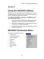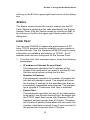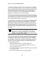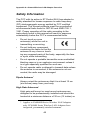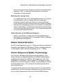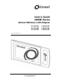
1
User’s Guide
4800B Series
Aironet Wireless LAN Adapter
PC4800B
PC4810B
PC4820B
LM4800B
LM4810B
LM4820B
DOC-710-005314-A0
Aironet Wireless Communications, Inc. • 3875 Embassy Parkway
Akron, Ohio 44333-8357
www.aironet.com
Aironet Wireless Communications, Inc.
No part of this document may be reproduced or transmitted in any means, electronic or mechanical, for any purpose, without the written permission of Aironet.
Information in this document is subject to change without notice. Aironet makes
no representation or warranties with respect to the contents of this manual and
specifically disclaims any express or implied warranties of merchantability or
fitness for any particular purpose.
© 1999 Aironet Wireless Communications, Inc.
All rights reserved.
AP4800TM, PC4800TM, PC4800BTM, PC4810BTM, PC4820BTM, LM4800TM,
LM4800BTM, LM4810BTM, LM4820BTM, and AironetTM are trademarks of Aironet
Wireless Communications, Inc.
Other trademarks used are properties of their respective owners.
Printed in USA
DOC-710-005314-A0
Table of Contents
About the User’s Guide ................................................. iii
Typographical Conventions.................................... iv
Section 1: Installing the Wireless LAN Adapter
Before You Start......................................................2
Installing the Wireless LAN Adapter........................3
Aironet Driver Installation Steps ..............................4
Section 2: Using the WinDGS Utilities
WinDGS Commands Menu ..........................................13
Select Card ...........................................................14
Load New Firmware ..............................................14
Edit Properties.......................................................14
Statistics ................................................................14
Status ....................................................................15
Link Test................................................................15
Site Survey ............................................................17
Radio Off/On .........................................................19
Exit ........................................................................19
Options Menu ...............................................................19
Preferences ...........................................................19
Core Dump ............................................................20
NDIS Driver Core Dump........................................20
Using Edit Properties....................................................20
System Parameters...............................................21
RF Network Parameters........................................23
Advanced (Infrastructure)......................................25
Advanced (Ad Hoc/IBSS) ......................................27
Using the Site Survey Active Mode Feature.................28
Destination MAC Address .....................................28
Continuous Link Test ............................................28
Destination is Another Aironet Device...................29
Number of Packets................................................29
Packet Size ...........................................................29
Data Retries ..........................................................29
Data Rates ............................................................29
Delay Between Packets ........................................29
Packet Tx Type .....................................................30
Percent Success Threshold ..................................30
Using the Linkscope Utility ...........................................31
Commands ............................................................31
Options ..................................................................32
Using the WEPKey Utility .............................................34
WEP Overview ......................................................34
i
Table of Contents
Using WEPKey......................................................34
Section 3: Error Messages and Troubleshooting
Error Messages and Troubleshooting ..........................41
Indicator LEDs.......................................................41
If Your Radio Fails to Establish Contact................43
Appendix A: Aironet Wireless LAN Adapter Overview
Aironet Wireless LAN Adapter Overview......................45
Safety Information .................................................46
Radio Characteristics ............................................47
Direct Sequence Radio Technology......................47
Data Transparency and Protocols.........................48
Protocols Supported..............................................48
Radio Ranges .......................................................48
Radio Antenna ......................................................50
Security Features ..................................................50
Terminology ..........................................................50
System Configurations ..........................................52
Coverage Options .................................................56
Appendix B: PC Card Specifications
PC Card Specifications ................................................59
LAN Drivers Supported .........................................59
Radio Specifications..............................................60
Power Requirements.............................................61
Physical Specifications..........................................61
Appendix C: Channels
Channels ......................................................................63
Appendix D: Declarations of Conformity
Declarations of Conformity ...........................................65
Appendix E: Technical Support
Technical Support ........................................................71
ii
About the User’s Guide
About the User’s Guide
This guide covers the installation, configuration, control,
and maintenance of your Aironet 4800B Series PC Card
Wireless LAN Adapter. The Guide is arranged as follows:
Section 1 – Installation – describes installation of the PC
Card.
Section 2 – Utilities – provides detailed procedures for
using the utilities to load new firmware versions, as well as
how to perform link tests and site surveys.
Section 3 – Error Messages and Troubleshooting –
provides detailed descriptions of the LED messages and
error codes, as well as general procedures for correcting
common problems.
Appendix A – Aironet Wireless LAN Adapter Overview –
provides a general introduction to the 4800B Series PC
Card, direct sequence radio technology, and the various
configurations you can use when operating the 4800B
Series PC Card in your infrastructure.
Appendix B – Specifications – provides radio and physical
specifications.
Appendix C – Channels – provides channel identifiers and
channel center frequencies for various area regulatory
agencies.
Appendix D – Declarations of Conformity – provides
conformity information about the 4800B Series Wireless
LAN Adapter.
Appendix E – Technical Support – provides contact
information for Aironet.
iii
About the User’s Guide
Typographical Conventions
When reading the User’s Guide and Technical Reference
Manual, it is important to understand the symbol and
formatting conventions used in the documentation. The
following symbols are used in the guide.
Convention
Type of Information
Indicates a note which contains important
information.
Indicates procedures which, if not observed,
could result in loss of data or damage to the
equipment.
Bold type
An action you must perform, such as typing a
character or making a selection with your
mouse.
iv
Section 1: Installing the Wireless LAN Adapter
Section 1
Installing the Wireless LAN
Adapter
This section describes the procedures for installing the
Wireless LAN Adapter.
Here’s what you’ll find in this section:
•
Before You Start
•
Installing the Wireless LAN Adapter
1
Section 1: Installing the Wireless LAN Adapter
Before You Start
For the PC Card to be used with a computing device (desktop personal computer, notebook, laptop computer, portable or hand-held device), the device must be equipped with
an internal or external PC Card Type II or Type III slot. All
drivers and supporting software (card and socket services)
for the PC Card slot must be loaded and configured.
Ask your system administrator for the following information,
which you may need to provide during driver installation:
•
Your Wireless Client Name
•
Your Wireless SSID
•
For Windows 98 networking, your computer name and
workgroup name
•
For your network account, your user name and password
•
Your IP address (unless using a DHCP server)
After unpacking the PC Card, make sure the following items
are present and in good condition:
•
PC4800B Wireless LAN Adapter
•
Aironet 4800 Series for Windows 95 & NT CD
•
Aironet 4800 Series for Windows 98 CD
If any item is damaged or missing, contact your Aironet supplier. Save all shipping and packing material to repack the
unit should service be required.
NOTE: Any remote antenna and its associated wiring for
an LM4800B Series Wireless LAN Adapter is ordered
and packed separately. (The integrated antenna on the
PC4800B Series Wireless LAN Adapter is permanently
attached.)
2
Section 1: Installing the Wireless LAN Adapter
Installing the Wireless LAN Adapter
This section provides instructions for installing an Aironet
client card on a computer using Windows 98, Windows 95,
and Windows NT.
Before you begin, examine the PC Card. One end is a dualrow, 68-pin PC Card connector. This side will be inserted
into the PC Card slot with the Aironet logo on the PC Card
facing up. The card is keyed so it can be inserted only one
way into the PC Card slot.
CAUTION: The following procedures and physical
connections apply generally to normal and conventional
PC Card slots. In the cases of custom or nonconventional equipment, be alert to possible differences
in PC Card slot configurations.
The PC Card can be connected to a PC Card Type II slot.
This includes slots that support both Type II and Type III
cards.
CAUTION: Do not force the PC Card into the PC Card
slot. Forcing it will damage both the PC Card and the slot.
If the PC Card does not go in easily, remove the card and
re-insert it.
3
Section 1: Installing the Wireless LAN Adapter
Aironet Driver Installation Steps
Installing the Driver for Windows 98
If the operating system on your computer is Windows 98,
follow these steps (if 95, see page 7; if NT, see page 9):
1. Remove all PC Cards from your computer and turn
it on.
2. Hold the Aironet 4800B Series Wireless LAN
Adapter with the label facing up, and insert the card
into the slot, applying just enough pressure to make
sure it is fully seated.
NOTE: The PC Card slot will be on the left or right side of
the computer, depending on the model.
CAUTION: Do not force the PC Card into the PC Card
slot. Forcing it will damage both the PC Card and the slot.
If the PC Card does not go in easily, remove the card and
re-insert it.
Windows 98 automatically detects the Aironet
4800B Series PC Card Wireless LAN Adapter,
briefly opens a New Hardware Found window, and
starts collecting information for a driver information
database.
When Windows 98 is ready to configure the new
hardware, it opens the Add New Hardware Wizard
dialog box. The dialog box states that Windows will
search for new drivers for the Aironet PC4800.
3. Click "Next." A dialog box appears asking what you
want Windows to do.
4. Select "Search for the best driver for your device
(Recommended)" and click "Next."
5. Select "CD-ROM drive," unselect all the other
options, insert the Aironet 4800B Series for Windows 98 CD, and click "Next."
4
Section 1: Installing the Wireless LAN Adapter
NOTE: If your computer doesn’t have a CD-ROM drive,
go to the Aironet website (www.aironet.com) and
download the drivers for your computer’s operating
system. Copy the drivers to a 3.5” floppy disk, and use
the floppy disk in place of the CD.
After the hardware wizard finds the installation files
on the CD, it displays the search results: "Windows
driver file search for the device: PC4800 DS Wireless PCMCIA LAN Adapter."
6. Click "Next" to copy the required files.
During the installation, you may be prompted with
dialog boxes asking you to enter a path to the
required Aironet or Windows 98 files.
If the Windows 98 files are installed on your computer, the Windows 98 files will usually be located
in the folder C:\Windows\Options\Cabs. Click "OK"
to copy the required files.
If Windows 98 prompts for the Windows CD, insert
the Windows 98 CD into your CD-ROM drive. If
your CD-ROM drive is drive D, the path in the dialog box should be D:\WIN98. Click "OK" to copy the
required files.
7. The Add New Hardware Wizard window appears
stating that Windows has finished installing the software that your new hardware device requires.
8. Click "Finish."
9. The Systems Settings Change window states: "To
finish setting up your new hardware, you must
restart your computer. Do you want to restart your
computer now?" Remove the CD and click "Yes" to
reboot the computer.
10. When the computer restarts, double-click the My
Computer icon on your desktop.
5
Section 1: Installing the Wireless LAN Adapter
11. In the My Computer window, double-click the Control Panel icon.
12. In the Control Panel window, double-click the Network icon.
13. Select the PC4800 DS Wireless PCMCIA LAN
Adapter. Click the Properties button.
14. On the PC4800 DS Wireless PCMCIA LAN Adapter
Properties window, click the Advanced tab.
15. In the Advanced window, select Client Name. Type
your computer's unique client name in the Value
dialog box.
16. Select SSID. Type your Access Point's SSID in the
Value dialog box. Click OK.
17. In the Network window, click OK.
18. The Systems Settings Change window states: "To
finish setting up your new hardware, you must
restart your computer. Do you want to restart your
computer now?" Click "Yes" to reboot the computer.
The driver installation is complete.
Contact your IS department if you have a problem
connecting to the network. Proxy server, network
protocols, and further authentication information
might be needed to connect to the network.
6
Section 1: Installing the Wireless LAN Adapter
Installing the Driver for Windows 95
If the operating system on your computer is Windows 95,
follow these steps (if 98, see page 4; if NT, see page 9):
1. Remove all PC Cards from your computer and turn
it on.
2. Hold the Aironet 4800B Series PC Card Wireless
LAN Adapter with the label facing up. Insert the
card into the PC card slot and apply just enough
pressure to make sure it is fully seated.
NOTE: The PC Card slot will be on the left or right side of
the computer, depending on the model.
CAUTION: Do not force the PC Card into the PC Card
slot. Forcing it will damage both the PC Card and the slot.
If the PC Card does not go in easily, remove the card and
re-insert it.
Windows 95 automatically detects the Aironet
4800B Series PC Card Wireless LAN Adapter,
briefly opens a New Hardware Found window, and
starts collecting information for a driver information
database.
When Windows 95 is ready to configure the new
hardware, it opens the Update Device Driver Wizard dialog box. The dialog box states that Windows
will complete the installation of the Aironet-PC4800.
3. Insert the Aironet 4800 Series for Windows 95 and
Windows NT CD and click Next.
7
Section 1: Installing the Wireless LAN Adapter
NOTE: If your computer doesn’t have a CD-ROM drive,
go to the Aironet website (www.aironet.com) and
download the drivers for your computer’s operating
system. Copy the drivers to a 3.5” floppy disk, and use
the floppy disk in place of the CD.
4. The Update Device Driver Wizard displays the following message: "Windows was unable to locate a
driver for this device." Click the Other Locations
button.
5. The Select Other Location window appears. Click
the Browse button.
6. Select your CD-ROM drive and click OK. At the
Select Other Location window, click OK.
7. The Update Device Driver Wizard window tells you
that it found the driver. Click Finish.
8. When prompted with "Please insert the disk labeled
'Windows 95 CD-ROM', and then click OK", just
click OK and do one of the following:
• If the Windows 95 files are installed on your computer, the Windows 95 files will usually be located
in the folder C:\Windows\Options\Cabs. Type
C:\Windows\Options\Cabs in the "Copy files
from:" dialog box. Click "OK" to copy the required
files.
• If Windows 95 prompts for the Windows CD,
insert the Windows 95 CD into your CD-ROM
drive. If your CD-ROM drive is drive D, the path in
the dialog box should be D:\WIN95. Click "OK" to
copy the required files.
9. The Systems Settings Change window states: "To
finish setting up your new hardware, you must
restart your computer. Do you want to restart your
computer now?" Remove the CD and click "Yes" to
reboot the computer.
10. When the computer restarts, double-click the My
Computer icon on your desktop.
8
Section 1: Installing the Wireless LAN Adapter
11. In the My Computer window, double-click the Control Panel icon.
12. In the Control Panel window, double-click the Network icon.
13. Select the PC4800 DS Wireless PCMCIA LAN
Adapter. Click the Properties button.
14. On the PC4800 DS Wireless PCMCIA LAN Adapter
Properties window, click the Advanced tab.
15. In the Advanced window, select Client Name. Type
your computer's unique client name in the Value
dialog box.
16. Select SSID. Type your Access Point's SSID in the
Value dialog box. Click OK.
17. In the Network window, click OK.
18. The Systems Settings Change window states: "To
finish setting up your new hardware, you must
restart your computer. Do you want to restart your
computer now?" Click "Yes" to reboot the computer.
The driver installation is complete.
Contact your IS department if you have a problem
connecting to the network. Proxy server, network
protocols, and further authentication information
might be needed to connect to the network.
Installing the Driver for Windows NT 4.0
If the operating system on your computer is Windows NT
4.0, follow these steps (if 98, see page 4; if 95, see page 7):
1. Turn your computer off.
2. Hold the Aironet 4800B Series PC Card Wireless
LAN Adapter with the label facing up. Insert the
card into the PC card slot and apply just enough
pressure to make sure it is fully seated.
9
Section 1: Installing the Wireless LAN Adapter
NOTE: The PC Card slot will be on the left or right side of
the computer, depending on the model.
CAUTION: Do not force the PC Card into the PC Card
slot. Forcing it will damage both the PC Card and the slot.
If the PC Card does not go in easily, remove the card and
re-insert it.
3. Turn your computer on, and wait for Windows NT to
fully start.
4. Insert the Aironet 4800 Series for Windows 95 & NT
4.0 CD into your CD-ROM drive.
NOTE: If your computer doesn’t have a CD-ROM drive,
go to the Aironet website (www.aironet.com) and
download the drivers for your computer’s operating
system. Copy the drivers to a 3.5” floppy disk, and use
the floppy disk in place of the CD.
5. Right-click on the Network Neighborhood icon on
your desktop and select Properties. (If your desktop
doesn't have a Network Neighborhood icon, open
the Control Panel, right-click the Network icon
there, and select Properties.)
6. Click the Adapters tab.
7. Click "Have Disk" at the Select Network Adapter
window.
8. Enter D:\ in the Copy files from box. (D:\ is the
drive letter of your CD-ROM drive. Your drive letter
may be different from this example.) Click OK.
9. In the Select OEM Option box, select the "Aironet
PC4800 PC Wireless LAN Adapter" option. Click
OK.
10. The Aironet Wireless Communications, Inc.
Adapter Setup window appears. In the Advanced
10
Section 1: Installing the Wireless LAN Adapter
window, select Client Name. Type your computer's
unique client name in the Value dialog box.
11. Select SSID. Type your Access Point's SSID in the
Value dialog box. Click OK.
12. Click Close.
13. When asked to shutdown and restart your computer, remove the CD-ROM disk and click Yes.
The driver installation is complete.
Contact your IS department if you have problems
connecting to the network. Proxy server, network
protocols, and further authentication information
might be needed to connect to the network.
Installing the Aironet 4800B Series PC Card Wireless
LAN Adapter Utilities
To install the WinDGS, LinkScope, and WEPKey utilities,
follow these steps:
1. Insert the Aironet 4800B Series CD for your operating system into your computer's CD-ROM drive.
2. Click Start > Run and type D:\utils\setup.exe where
"D" is your CD-ROM's drive letter.
3. Follow the setup instructions on the screen to complete the installation.
Refer to Section 2 of this User Guide for details on using
each utility.
11
Section 1: Installing the Wireless LAN Adapter
12
Section 2: Using the WinDGS Utilities
Section 2
Using the WinDGS Utilities
WinDGS is used to perform user-level diagnostics on your
Aironet Wireless LAN Adapter Card in the Windows 95, 98,
and NT operating system environments.
To install the WinDGS, LinkScope, and WEPKey utilities, follow these steps:
1. Insert the Aironet 4800B Series CD for your operating system into your computer's CD-ROM drive.
2. Click Start > Run and type D:\utils\setup.exe where
"D" is your CD-ROM's drive letter.
3. Follow the setup instructions on the screen to complete the installation.
WinDGS Commands Menu
The Commands Menu includes:
•
Select Card
•
Load New Firmware
•
Edit Properties
•
Statistics
•
Status
•
Link Test
•
Site Survey
•
Radio Off/On
•
Exit
13
Section 2: Using the WinDGS Utilities
Select Card
This allows another installed Aironet Wireless LAN Adapter
Card to be chosen. The property screens will change to
reflect the parameters specific to each card type.
Load New Firmware
The firmware is contained in the card’s flash memory. Flash
memory allows for easy updating of the firmware as necessary.
Upgrading Firmware for Windows 95, 98, and NT
The WinDGS program is used to load new firmware.
To load new firmware:
1. Make sure the PC Card is up and running.
2. Select Commands.
3. Select Load New Firmware.
4. Select Look In....Use the drop down button to select
the appropriate path and image file.
5. Select Open. This will flash the card with the selected
image.
Edit Properties
WinDGS allows you to change the configuration parameters of your currently installed Aironet 4800B Series Wireless LAN Adapter. See “Using Edit Properties” on page 20
for details on this command.
Statistics
The Statistics screen shows the current statistics from the
PC Card. Statistics are updated at the rate specified by the
Screen Update Timer. Clear the current statistics by clicking
on Reset. Exit the Statistics screen by clicking on OK, or by
14
Section 2: Using the WinDGS Utilities
clicking on the X in the upper right hand corner of the dialog
box.
Status
The Status screen shows the current status from the PC
Card. Status is updated at the rate specified by the Screen
Update Timer. Exit the Status screen by clicking on OK, or
by clicking on the X in the upper right hand corner of the
dialog box.
Link Test
You can use WinDGS to assess the performance of RF
links. TCP/IP protocol must be installed on your system to
run this link test. See the Windows 95/98/NT Help for more
information on installing and setting up TCP/IP. An IP
address must also be configured for the Access Point.
1. From the Link Test command menu, enter the following
parameters:
•
IP address of Aironet Access Point:
This parameter specifies the IP address of the
Access Point with which you want to test the RF link.
Set this value before running the link test.
•
Number of Packets:
This parameter specifies the number of packets the
link test will attempt to send. The display will show
the number of packets of the specified size that are
successfully transmitted and received. This parameter is ignored if Continuous Link Test is selected.
•
Packet Size:
This parameter specifies the size of the data packet
to be sent to the Aironet Access Point. Be aware that
the TCP/IP stack that comes with Windows 95 will
fragment packets greater than 512 bytes. Therefore,
the number of packets transmitted will not match the
number of packets received (even if none are lost) if
the packet size is greater than 512 bytes.
15
Section 2: Using the WinDGS Utilities
•
Continuous Link Test:
Selecting this item causes the link test to run continuously until Stop, OK, or Cancel is selected. The
Number of Packets parameter is ignored if Continuous Link Test is selected.
2. Once the parameters have been entered, click on the
Start button at the bottom of the dialog box to start the
link test. When the link test is running, necessary statistics will be displayed and updated periodically.
3. To stop the link test, click on Stop, OK, or Cancel at the
bottom of the dialog box. Once the link test has sent the
number of packets specified, the Stop button will toggle
back to a Start button.
Using Windows 95 or Windows 98 to Perform a Link
Test Through Telnet
You can perform a link test outside the WinDGS Utility
through a telnet session. Follow these steps:
1. Install the drivers.
2. Configure the drivers for network operation.
3. Ensure unique IP assignments of mobile/portable
PC Card devices and Aironet Access Point.
4. Set up an Aironet Access Point for the intended
operation (set fragmentation thresholds, RTS
thresholds, etc.)
5. Start the operating system on the mobile station.
6. Configure the adapter.
7. Make sure the mobile station is associated to the
Aironet Access Point.
8. Start a telnet session on the mobile station to the
Aironet Access Point. Depending on the system in
use, the telnet application may have logging and
note taking capability. If so, enable these modes.
9. Navigate through the Aironet Access Point menu to
the link test option. See the appropriate Access
16
Section 2: Using the WinDGS Utilities
Point Technical Reference Manual for more information.
10. Set up the test options to accurately model the
system.
11. Set the test for continuous operation with a
1-second delay.
12. Begin traversing the area around the Aironet
Access Point to determine its coverage. If logging
and notes are not possible with the telnet application, maintain a manual log.
The telnet session packets are interspersed with test
packets which may increase the round-trip time for some
frames. The link test will show progress changes as the test
is being conducted.
The first-time delivery success rate for the packet may not
be important for transaction-based systems, and can result
in a slightly larger range. Using longer packets can provide
some degree of safety margin in the range estimate.
NOTE: Roundtrip time will be affected by the telnet
session maintenance.
Site Survey
To perform a meaningful site survey, you need to conduct a
test that will accurately model the intended use of the system. It is important to perform a site survey using equipment
which is similar to the equipment that will be implemented.
Common survey items include:
•
Transmit power
•
Antenna type(s)
•
Antenna location(s)
•
Packet (fragment) size
•
Interference
17
Section 2: Using the WinDGS Utilities
You should always conduct a site survey with all variables
set to the operational values. You should also try to perform
the survey during the time the RF link will generally be functioning with all other systems and noise sources operational. For efficiency, you should execute the site survey
application entirely from the mobile station.
The link test tool helps determine the RF network coverage.
The results of the link test will help eliminate low RF signal
level areas that can result in loss of connection between the
PC Card and the Aironet Access Point.
It is important to remember the information being displayed
is from the Aironet Access Point’s viewpoint. Therefore,
packets sent are from the Aironet Access Point to the PC
Card client. Packets received are from the PC Card to the
Aironet Access Point. Signal quality is an estimate of the
signal strength recorded at the time of packet reception by
the radio.
NOTE: If your Wireless LAN Adapter contains new
firmware, you can use WinDGS’s Active Mode
Survey. See “Using the Site Survey Active Mode
Feature” on page 28 for details.
The Overall Link Quality rating on the Site Survey window
indicates the ability of the Aironet Wireless LAN Adapter to
successfully communicate with an Access Point. Ratings
are Excellent, Good, Fair, and Poor. The rating is derived
from the Current Signal Strength (PC4500/PC4800) and
Current Signal Quality.
•
Excellent: Both values are greater than 75%
•
Good: Both values are greater than 40%, but one or
both are less than 75%
•
Fair: Both values are greater than 20% but one or both
are less than 40%
•
Poor: One or both values are less than 20%
18
Section 2: Using the WinDGS Utilities
Radio Off/On
Radio Off/On allows you to selectively turn off or on the
power to the radio. Turning the radio off prevents all RF
energy from being transmitted by the PC Card.
Exit
Closes all windows and exits WinDGS.
Options Menu
The Options Menu includes:
•
Preferences
•
Core Dump
•
NDIS Driver Core Dump
Preferences
The WinDGS Preferences allow you to customize various
parameters that control the operation of WinDGS. For
example, you can set the rate at which the values are
updated in the status and statistics screens via the Screen
Update Timer. You can also set the Save Properties
Options, which controls what is done with changes to the
current settings.
Screen Update Timer
The Screen Update Timer controls how often the statistics
and status screens are updated. The screen can be
updated in one second increments, from once a second to
once every 60 seconds. The default is once every five seconds. You can use either the edit box or the slider to
change this value.
19
Section 2: Using the WinDGS Utilities
Status Bar Options
Use the Status Bar Options to include seconds on the clock
display on the WinDGS main screen.
Core Dump
Core Dump allows you to perform a core dump of the Wireless LAN Adapter’s firmware. Enter file names for core
dumps 1 and 2, or accept the defaults (C:\Aironet\WinDGS\Core4800.1 and Core4800.2). Click the Do Core
Dump button to perform the dump.
NDIS Driver Core Dump
NDIS Driver Core Dump allows you to perform a core dump
of the Wireless LAN Adapter’s drivers. Enter a file name for
the core dump, or accept the default (C:\Aironet\WinDGS\Core4800.cor). Click the Do Core Dump button to perform the dump.
Using Edit Properties
The Edit Properties screen, which
you access from
the Commands
menu, includes
four “pages,”
which you select
by clicking the
tabs at the top of
the window:
•
System
Parameters
•
Network
Parameters
20
Section 2: Using the WinDGS Utilities
•
RF Network Parameters
•
Advanced (Infrastructure or Ad Hoc)
Each sub-screen is described below.
System Parameters
System parameters include:
•
Name
•
SSID
•
Network Type (Infrastructure or Ad Hoc)
•
Constant Awake Mode (CAM)
•
Power Save Mode
•
Fast Power Save Mode
•
Maximum Power Save Mode
Name
The station name is displayed in the table of connected
devices on the Access Point. It provides a logical name
to determine which machines are connected without
having to memorize every MAC address. The name
can be up to 16 characters.
SSID
The Service Set Identifier (SSID) controls access to a
given wireless network. This value MUST match the
SSID of any/all Access Points that you want to communicate with. If the value does not match, access to the
system is not granted. The SSID can be up to 32 characters (case sensitive).
Network type (Infrastructure Mode)
This mode is used to set up a connection to a wired
network, such as Ethernet or Token Ring. This mode
requires an Access Point to gain access to the wired
network.
21
Section 2: Using the WinDGS Utilities
Network type (Ad Hoc Mode)
This mode is used to set up a small, temporary network
between two or more computers. For example, you
might set up an ad hoc network between computers in
a conference room so users can share information in a
meeting.
Constant Awake Mode (CAM)
Constant Awake Mode is the normal mode for desktop
machines or other machines where power consumption
is not an issue. It keeps the radio powered up continuously so there is little latency for responding to
messages. This mode is recommended for devices
where high availability is desired.
Power Save Mode
Power Save Mode is recommended for devices where
power consumption is a major concern, such as small
battery powered devices. If the client node is powered
from an AC line, PSP should not be used. Power Save
Mode causes the Access Point to buffer incoming messages. The Aironet 4800B Series Wireless LAN
Adapter must wake up periodically and poll the Access
Point to see if there are any buffered messages waiting.
The PC Card can request each message and then go
back to sleep.
Fast Power Save Mode
Fast Power Save Mode (Fast PSP Mode) switches
between PSP and CAM based on network traffic. When
retrieving a high number of packets, Fast PSP Mode
will switch to CAM to retrieve the packets. Once the
packets are retrieved, it switches back to PSP.
Maximum Power Save Mode
Maximum Power Save Mode (Max PSP Mode) can only
be used in conjunction with PSP or Fast PSP
Modes.This mode allows the Aironet 4800B Series
22
Section 2: Using the WinDGS Utilities
Wireless LAN Adapter to conserve the most power
while still maintaining an infrastructure connection.
Using Max PSP Mode conserves power but will reduce
throughput.
RF Network Parameters
RF Network Parameters include:
•
Fragment Threshold: This parameter defines a
threshold above which the RF packet will be split up or
fragmented. If a packet is fragmented or transmission
of part of it is interfered with, only the portion that was
unsuccessful would need to be re-sent. The throughput
will generally be lower for fragmented packets since the
fixed packet overhead consumes a higher portion of the
RF bandwidth.
•
Data Retries: This parameter defines the number of
times a packet will be re-sent if the initial transmission
is unsuccessful. If the network protocol automatically
re-tries itself, set this to a small value. A “bad” packet
status will be sent up the protocol stack more quickly so
the application can re-transmit the packet.
•
Data Rate: This parameter determines the data rate
used to transfer all management frames by the client
device when associated within a given Basic Service
Set (BSS). When operating in Infrastructure Mode, this
parameter should be set to correspond to the Access
Point setting. When operating in Ad Hoc Mode, all stations should have the same setting.
Model
4800B Series
•
Allowable Selections
Auto Rate Selection, 1 Mbps Only, 2 Mbps
Only, 5.5 Mbps Only, or 11 Mbps Only
Authentication type: This parameter controls the validation of the WEP Key. Shared Key Authentication validates that the client is using the same WEP Key as the
Access Point. The Access Point sends a known, un23
Section 2: Using the WinDGS Utilities
encrypted “challenge packet” to the client. The client
then encrypts the challenge packet and sends it back to
the Access Point. The Access Point then attempts to
decrypt the encrypted challenge packet, and sends an
Authentication response packet indicating the success
or failure of the decryption back to the client. Open
Authentication does not check for a matching WEP
Key. The Shared Key selection is not available if the client’s WEP Key is not set.
•
Modulation: This parameter determines the type of
radio modulation that the Wireles LAN Adapter uses at
the 5.5 Mbps and 11 Mbps data rates. Older versions of
firmware use MOK modulation, while newer firmware
versions use the IEEE 802.11 Standard CCK modulation. The modulation that the PC4800 uses must match
the modulation of the Access Point (in an Infrastructure
Mode configuration) or other Wireless LAN Adapters (in
an Ad Hoc Mode configuration). Otherwise, the radio
will not communicate with the other devices.
•
Use Short Radio Headers: Select this checkbox to use
short radio headers when transmitting. Short radio
headers improve throughput performance. Long radio
headers ensure compatibility with all models of Aironet
Wireless LAN adapters. The PC4800B Series Wireless
LAN Adapter supports short radio headers, but earlier
models of Aironet's Wireless LAN Adapter (PC4800
and PC4800A) require long headers.
•
Channel: Use this parameter to select the radio channel the PC card will use. Channel 6 (2437 MHz) is the
default setting.
•
Transmit Power: Use this parameter to set the transmit power of the card to 1 mW, 5 mW, 20 mW, 50 mW,
or 100 mW.
•
Allow Association To Mixed Cells: Select this checkbox to allow the PCI/ISA Wireless LAN Adapter to communicate with mixed cells. A mixed cell is a radio
network in which some devices use WEP and some do
not.
24
Section 2: Using the WinDGS Utilities
•
Enable WEP: Select this checkbox to enable WEP
(Wired Equivalency Protocol). The checkbox will be
inaccessible (grayed-out) until you set a WEP key using
the WEPKey utility (see page 34).
Advanced (Infrastructure)
The following parameters are contained in both the Infrastructure and Ad Hoc Modes:
•
Antenna Mode
•
Specified Access Point
•
RTS Threshold
•
RTS Retry Limit
Antenna Mode
The PC4800B Series Wireless LAN Adapter has an
integrated, permanently attached antenna, and is
always set to Diversity mode.
For the LM4800B Series Wireless LAN Adapter, three
options are available for the type of antenna you have
connected to the LM4800B Series card:
•
Antenna Diversity: This allows the LM Card to use
the stronger signal from the two antenna ports.
Diversity can help the radio maintain the RF
connection in areas of interference. Due to the
nature of how RF signals are affected by the
surroundings, one antenna may be in an RF “null”
where the signal is very weak, but the other
antenna (even though it is only a small distance
away) may have a stronger signal strength. The PC
Card would automatically select the antenna that
has the highest signal strength. Antenna Diversity
is the recommended setting for the standard
antenna.
•
Right Antenna Only (J1): Choose this option if the
antenna you are using is connected to the right
antenna port. The LM Card will not attempt to com25
Section 2: Using the WinDGS Utilities
municate using the left antenna port since no
antenna is connected to it.
•
Left Antenna Only (J2): Choose this option if the
antenna you are using is connected to the left
antenna port. This tells the LM Card not to attempt
to communicate using the right antenna port since
no antenna is connected to it.
Specified Access Point
This parameter is the MAC address of the preferred
Access Point you want to associate with. It is important
to note that if you specify the Access Point, you MAY
associate to another Access Point if the Specified
Access Point is not found. If you roam out of range, you
will probably associate with another Access Point.
Setting a Specified Access Point will slow down the
roaming process. Thus, for normal operation for the
majority of users, leave this field blank.
RTS Threshold
This parameter controls what size data packet the low
level RF protocol issues to an RTS packet. There are
several trade-offs to consider when setting this
parameter. Setting this parameter to a small value
causes RTS packets to be sent more often, consuming
more of the available bandwidth, therefore reducing the
apparent throughput of other network packets. However, the more often RTS packets are sent, the quicker
the system can recover from interference or collisions.
Refer to the IEEE 802.11 Standard for more information
on the RTS/CTS mechanism.
RTS Retry Limit
This parameter controls the number of times the PC
Card will re-send the RTS packet if it does not receive a
CTS from the previously sent RTS packet. Setting this
to a large value will decrease the available bandwidth
whenever interference is encountered, but will make
26
Section 2: Using the WinDGS Utilities
the system more immune to interference and collisions.
Refer to the IEEE 802.11 Standard for more information
on the RTS/CTS mechanism.
Advanced (Ad Hoc/IBSS)
In Ad Hoc Mode, you can also modify the following
parameters:
•
Channel
•
Beacon Period
•
Wake Duration
Channel
This parameter specifies the channel identifier the unit
will use if it must start its own network. For all other situations, the radio will scan for the proper frequency. See
Appendix C for channel identifier parameters.
Beacon Period
This parameter specifies the duration between beacon
packets that are used by IEEE 802.11 systems to
synchronize the “hops” (change to another frequency).
The beacon packet contains timing information and hop
pattern information that is broadcast over the airwaves.
Any station that can hear the beacon packet can then
synchronize their internal timer so that it can hop at the
correct time. The default beacon period is one-half of
the dwell period so two beacons are transmitted per
hop dwell period (default is 100 Kµsec). Refer to the
IEEE 802.11 Standard for more information on the
timing and scanning mechanism.
Wake Duration
This parameter specifies the amount of time per Hop
Dwell Period that the adapter stays awake listening for
data packets. This is only used in Power Save Mode.
27
Section 2: Using the WinDGS Utilities
Using the Site Survey Active
Mode Feature
If your PC4800B Series Wireless LAN Adapter contains the
latest firmware, and if you have the latest drivers on your
system, you can use the Site Survey Active Mode feature to
set up a customized link test.
When you select
Site Survey from
the Commands
menu and click
the Setup button at the bottom of the
window, the
Setup window
appears. Each
setting is
described
below.
Destination MAC Address
This parameter specifies the Access Point that will be
involved in the test. The default is the MAC address of the
AP the Aironet Wireless LAN Adapter is currently associated with.
Continuous Link Test
If you click this check box, the Active Mode test will run
repeatedly until you press the OK or Stop buttons on the
Site Survey page. (The test will loop repeatedly for the num28
Section 2: Using the WinDGS Utilities
ber of packets you specify on the Number of Packets setting.)
Destination is Another Aironet Device
Click this check box if the Access Point you named in the
Destination MAC Address field is an Aironet Access Point.
Number of Packets
This parameter sets the quantity of packets that will be sent
during the test.
Packet Size
This parameter sets the size of the packets that will be sent
during the test. You should use a packet size that will be
typical during normal use of the system.
Data Retries
This parameter sets the number of times a transmission will
be retried if an ACK is not returned by the destination
device. Click None for no retries, or Default Retries for the
firmware’s default value for retries.
Data Rates
This parameter sets the bit rate at which packets will be
transmitted. No rate shifting will occur during the test.
Delay Between Packets
This parameter sets the delay (in milliseconds) between
successive transmissions.
29
Section 2: Using the WinDGS Utilities
Packet Tx Type
This parameter sets the packet type that will be used during
the test. If you select Unicast, the system will expect an
ACK back from the destination, and retries can occur. If you
select Multicast, no packet retries will occur during the test.
Percent Success Threshold
This parameter controls the red line on the “Percent Successful” histogram. Percentages greater than or equal to
this value will show up as green bars, while percentages
below this value will show up as yellow bars on the Percent
Successful histogram.
When the Site Survey Active Mode is running, this window
appears:
30
Section 2: Using the WinDGS Utilities
Using the Linkscope Utility
The Linkscope utility provides a graphical display of:
•
Signal Quality
•
Signal Strength
Linkscope determines the
performance of the RF link
between a PC Card and an
Aironet Access Point. Any
Windows 95, Windows 98,
or Windows NT unit associated to an Aironet Access
Point can run the linkscope test.
Signal strength is displayed
along the vertical axis of
the graphical display. Signal quality is displayed
along the horizontal axis. The combined result is represented by a diagonal line. The Aironet Access Point associating with the PC Card is indicated along the bottom of the
display as well as its MAC address.
Commands
The Commands pull-down menu includes the following
commands:
Select Card
Use Select Card if you have more than one Wireless
LAN Adapter installed on your computer. A window
appears that allows you to choose the card you want to
examine with Linkscope.
Exit
Use Exit to close the Linkscope utility.
31
Section 2: Using the WinDGS Utilities
Options
The Options pull-down menu includes the following options:
Preferences
When you select Preferences, this window appears:
Four parameters are available on the Preferences window:
•
Screen Updates Per Minute: This parameter sets
the screen update frequency on the Linkscope
32
Section 2: Using the WinDGS Utilities
main window. Type a value in the entry field or use
the slider bar to adjust the setting.
•
Display Icon in Systray when Minimized: Select
this checkbox to display a Linkscope icon at the
bottom of your screen when Linkscope is minimized. The Icon type options allow you to choose
the information that appears when you hold your
mouse pointer on the icon.
•
Display Tx and Rx Retry Rates: Select this checkbox to display Tx and Rx rates on the Linkscope
main screen.
•
Display History: Select this checkbox to display
the signal history on the Linkscope main screen. At
each screen update, a black dot appears for that
status.
33
Section 2: Using the WinDGS Utilities
Using the WEPKey Utility
This section briefly explains how to use the Aironet WEPKey Utility to configure a WEP key on the Aironet client
card.
WEP Overview
WEP-40 and WEP-128 are optional IEEE 802.11 features
that provide data confidentiality equivalent to the confidentiality of a wired LAN that does not use cryptographic techniques to enhance privacy. WEP (Wired Equivalent
Privacy) makes the wireless LAN link in a system only as
secure as the wired link.
As specified in the standard, WEP uses the RC4 algorithm
with a 40-bit key for WEP-40 and a 128-bit key for WEP128. When WEP is enabled, each station (client and
Access Point) has a key. The key scrambles the data
before it is transmitted over the airwaves. If a station
receives a packet that is not scrambled with the appropriate
key, the station discards the packet and never delivers it to
the host.
Using WEPKey
1. Install the Aironet WEPKey Utility (along with
WinDGS and LinkScope) from the Aironet Wireless
LAN Adapter Utility disk.
2. Start the application with one of these steps:
• Double-click the WEPKey icon on the Desktop,
or
•
From the Windows Start Menu, select Programs | Aironet | WEPKey, or
•
From a DOS Window, change to the C:\Aironet\WinDGS directory (or to the directory you
selected when installing WinDGS) and type
wepkey.
34
Section 2: Using the WinDGS Utilities
The following login screen appears:
Passwords are case sensitive, and can contain up
to 256 characters. The default password is Aironet
(upper-case A followed by lower-case ironet).
3. Enter the correct password and click OK. The main
screen appears:
The Commands pull-down menu provides options
that allow you to select a wireless adapter card,
change the password, and enter a WEP key.
35
Section 2: Using the WinDGS Utilities
To enable or disable WEP, set the WEP key with
the WEPKey utility, and then open WinDGS. At the
WinDGS main screen, select Edit Properties from
the Commands pull-down menu. Click the RF Network tab. The Enable WEP checkbox is in the bottom left corner of the window.
4. If you have more than one adapter card installed on
your computer, you can use the WEPKey utility to
select the card you want to use. To select an
adapter card, choose Select Card from the Commands pull-down menu. This screen appears:
Highlight the card you want to use, and click OK to
select it.
5. To change the default password, select Change
Password from the Commands pull-down menu.
This screen appears:
36
Section 2: Using the WinDGS Utilities
Passwords are case sensitive, and can contain up
to 256 characters. The default password is Aironet
(upper-case A followed by lower-case ironet).
6. To enter a WEP Key, choose Enter WEP Key from
the Commands pull-down menu on the main
screen. This screen appears:
You can create up to four WEP Keys. Ten characters are required for WEP-40 keys. Twenty-six
characters are required for WEP-128 keys.
Select the size of each key by clicking the 40 or
128 button beside each key entry field.
37
Section 2: Using the WinDGS Utilities
Click the Transmit Key button next to the key you
want to use.
A check appears in the Already Set box next to
existing keys. To protect key security, existing key
codes do not appear in the key entry fields. You
can write over existing keys, but you cannot edit
them or delete them.
There are two types of WEP Keys: Temporary and
Persistent. You should choose Persistent if you
want the card to retain the WEP Key when you
reboot the machine.
NOTE: Entering a WEP key does not enable WEP. To
enable or disable WEP, set the WEP key with the
WEPKey utility, and then open WinDGS. At the WinDGS
main screen, select Edit Properties from the Commands
pull-down menu. Click the RF Network tab. The Enable
WEP checkbox is in the bottom left corner of the window.
7. If you purchase WEP as an upgrade for your Wireless LAN Adapter, you need to enter the WEP
Option Code. Aironet or your Aironet reseller will
give you the Option Code when you purchase the
feature.
Select Option Code from the Commands pull-down
menu. This screen appears:
38
Section 2: Using the WinDGS Utilities
Type the Option Code and click OK. You can then
set up WEP keys and use the WinDGS utility to
enable WEP.
8. You can exit the WEPKey utility by selecting Exit
from the Commands menu.
39
Section 2: Using the WinDGS Utilities
40
Section 3: Error Messages and Troubleshooting
Section 3
Error Messages and Troubleshooting
The Wireless LAN Adapter provides LED messages and
error codes. This section provides the general procedures
for correcting common problems encountered when
installing the PC Card system.
Indicator LEDs
The PC Card has two indicator LEDs (green and amber) on
the face of the card.
The green indicator is the Link Integrity/Power LED. It lights
when the card is receiving power and flashes slowly when
the PC Card is linked with the network.
The amber indicator is the Link Activity LED. It flashes when
the PC Card is receiving or transmitting data or in a pattern
to indicate an error condition.
See Tables 3.1 and 3.2 for an explanation of the LED
Messages.
41
Section 3: Error Messages and Troubleshooting
Table 3.1 – Green LED Operating Messages
Green LED
Condition
Off
No power or error
Flashing Quickly
Power on, self-test OK, scanning for network
Flashing Slowly
Associated with an infrastructure network
Table 3.2 – Amber LED Operating Messages
Amber LED
Green LED
Condition
Flashing
Continuously on or
flashing slowly
PC Card is transmitting or
receiving data while
associated with an Access
Point
Flashing in a Pattern
Continuously on
Indicates an error
condition
42
Section 3: Error Messages and Troubleshooting
If Your Radio Fails to Establish Contact
•
Change your location or the location of the antenna by
a few feet and try again.
•
Make sure the antenna is securely attached.
•
Make sure the PC Card is securely inserted in the PC
Card slot.
•
Make sure the receiving equipment is turned on and
operating.
•
Make sure the receiving equipment is properly connected to the host computer.
•
Check that all parameters are set properly for both the
PC Card and the Aironet Access Point.
If the radio fails to establish contact, contact Aironet Technical Support for additional assistance:
Phone
Fax
e-mail
- (330) 664-7903
- (330) 664-7990
- [email protected]
http://www. aironet.com
43
Section 3: Error Messages and Troubleshooting
44
Appendix A: Aironet Wireless LAN Adapter Overview
Appendix A
Aironet Wireless LAN Adapter
Overview
The Aironet 4800B Series Wireless LAN Adapter is a PC
Card radio module that provides transparent wireless data
communications between fixed, portable, or mobile devices
and other wireless devices or a wired network infrastructure. Host devices can be any device equipped with a PC
Card Type II or Type III slot. These devices include:
•
Desktop systems
•
Portable laptops
•
Notebook computers
•
Personal digital assistants
•
Pen based computers
•
Other data collection devices
The PC Card is fully compatible when used in a device supporting Plug-and-Play (PnP) technology.
The PC Card can also be built into peripheral devices such
as printers to provide a transparent wireless connection to a
wired network.
45
Appendix A: Aironet Wireless LAN Adapter Overview
Safety Information
The FCC with its action in ET Docket 96-8 has adopted a
safety standard for human exposure to radio frequency
(RF) electromagnetic energy emitted by FCC certified
equipment. The Aironet products meet the uncontrolled
environmental limits found in OET-65 and ANSI C95.1,
1991. Proper operation of this radio according to the
instructions found in this manual will result in exposure
substantially below the FCC’s recommended limits.
•
Do not touch or move
antenna(s) while the unit is
transmitting or receiving.
•
Do not hold any component
containing the radio so that the
antenna is very close or touching any exposed parts of the body, especially the face
or eyes, while transmitting.
•
Do not operate a portable transmitter near unshielded
blasting caps or in an explosive environment unless it
is a type especially qualified for such use.
•
Do not operate radio or attempt to transmit data unless
the antenna is connected; if the antenna is not connected, the radio may be damaged.
Dipole Antenna*
Always orient the antenna so that it is at least 15 cm
(six inches) away from your body.
High Gain Antennas*
High gain wall mount or mast mount antennas are
designed to be professionally installed and should be
located at a minimum distance of 30 cm (12 inches) or
* Applies to LM4800B Series Wireless LAN Adapters
only. PC4800B Series Wireless LAN Adapters have
integrated, permanently attached antennas.
46
Appendix A: Aironet Wireless LAN Adapter Overview
more from your body. Please contact your professional
installer, VAR, or antenna manufacturer for proper
installation requirements.
Warning for Laptop User
To comply with the FCC RF exposure limits, it is recommended when using a laptop with the integrated
antenna, that the antenna should not be positioned
closer than 5 cm (two inches) from your body or nearby
persons for extended periods of time while it is transmitting (or operating). If the antenna is positioned less than
5 cm (two inches) from the user, it is recommended that
the user limit exposure time.
Other Devices in the Wireless Network
Refer to the User’s Guide and Technical Reference
manual for the Access Point, Universal Client, or Bridge
for additional information.
Radio Characteristics
The PC Card operates in the 2.4 GHz license-free Industrial
Scientific and Medical (ISM) band. Data is transmitted over
a half-duplex radio channel operating up to 11 Mbps.
Direct Sequence Radio Technology
The Aironet 4800B Series Wireless LAN Adapter uses
Direct Sequence Spread Spectrum (DSSS) transmission
originally developed for military “anti-jamming” and “low
probability of intercept” radio systems. The signal is transmitted over a wide frequency range, using multiple frequencies simultaneously. This protects the data transmission
from interference.
If a particular frequency encounters a level of noise and/or
interference, there is enough redundancy built into the signal on other frequencies that the Aironet 4800B Series
47
Appendix A: Aironet Wireless LAN Adapter Overview
Wireless LAN Adapter will usually still be successful in its
transmission.
Data Transparency and Protocols
The Aironet 4800B Series Wireless LAN Adapter transports
data packets transparently as they move through the wireless infrastructure. The PC Card operates similarly to a
standard network product except the wire is replaced with a
radio connection. No special wireless networking functions
are required. All existing applications, which operate over a
network, will operate using the Aironet 4800B Series Wireless LAN Adapter.
Protocols Supported
The Aironet 4800B Series Wireless LAN Adapter can be
used in a variety of infrastructure configurations. Aironet
Access Points provide connections to wired network. When
using the Aironet standard device drivers, the PC Card is
fully compliant with the following operating systems:
Drivers
Operating System
NDIS3
Windows 95
NDIS4
Windows NT
NDIS5
Windows 98, Windows 2000
Radio Ranges
This section provides general guidelines on factors that
influence network performance (see Section 2 - Site
Survey and Link Test).
Site Survey
Because of differences in component configuration,
placement and physical environment, every network
48
Appendix A: Aironet Wireless LAN Adapter Overview
application is a unique installation. Before installing the
system, users should perform a site survey to determine the optimum utilization of networking components
and to maximize range, coverage and network performance.
Here are some operating and environmental conditions you
should consider:
•
Data Rates. Sensitivity and range are inversely proportional to data bit rates. The maximum radio range is
achieved at the lowest workable data rate. There will be
a decrease in receiver threshold sensitivity as the radio
data rate increases.
•
Antenna Type and Placement. Proper antenna configuration is a critical factor in maximizing radio range.
As a general guide, range increases in proportion to
antenna height.
For a detailed explanation of antenna types and configurations along with guidelines on selecting antennas for
specific environments, see the Aironet Antenna Guide.
•
Physical Environments. Clear or open areas provide
better radio range than closed or filled areas. Also, the
less cluttered the work environment, the greater the
range.
•
Obstructions. A physical obstruction such as metal
shelving or a steel pillar can hinder the performance of
the PC Card, particularly when using the small integrated antenna. Avoid locating the computing device
and antenna in a location where there is a metal barrier
between the sending and receiving antennas.
•
Building Materials. Radio penetration is greatly influenced by the building material used in construction. For
example, drywall construction allows greater range
than concrete blocks. Metal or steel construction is a
barrier to radio signals.
49
Appendix A: Aironet Wireless LAN Adapter Overview
Link Test
The link test tool is used to determine RF coverage.
The test results help the installer eliminate low RF signal level area that can result in loss of connection.
Radio Antenna
The integrated diversity antenna comes standard with the
PC Card and provides omni-directional coverage.
A benefit of the diversity antenna system is improved coverage. At the edges of the RF coverage or fringe areas, there
are often multiple signals reaching the receiver, all from the
same transmitter. These signals travel in different paths
(multipath) and are caused by reflection and shadows of the
RF signals. When the signals combine, the receiver may
have trouble decoding the data. The Aironet radio’s ability
to switch and sample between these antennas allows it to
select the optimum antenna for receiving the packet.
Security Features
The Aironet 4800B Series Wireless LAN Adapter employs
Direct Sequence Spread Spectrum Technology, previously
developed for military “anti-jamming” and “low probability of
intercept” radio systems.
The Aironet Access Point must be set to the same Service
Set Identifier (SSID) as all other Aironet devices on the
wireless infrastructure. Units with a different SSID will not
be able to directly communicate with each other.
Terminology
When configuring your system, and when reading this manual, keep in mind the following terminology:
Association – Each root unit or repeater in the infrastructure contains an association table that controls the routing
of packets between the Access Point and the wireless infra50
Appendix A: Aironet Wireless LAN Adapter Overview
structure. The association table maintains entries for all the
nodes situated below the Access Point on the infrastructure
including repeaters and client nodes.
End Node – A client node that is located at the end of the
Network Tree.
Infrastructure – The wireless infrastructure is the communications system that combines Access Points, mobile
nodes and fixed nodes. Access Points within the infrastructure can be either root units, which are physically wired to
the LAN backbone, or can act as wireless repeaters. Other
RF enabled devices serve as fixed nodes or mobile client
nodes.
Parent/Child Node – Refers to the relationships between
nodes in the wireless infrastructure. The complete set of
relationships is sometimes described as a Network Tree.
For example, the Access Point (at the top of the tree) would
be the parent of the end nodes. Conversely, the end nodes
would be the children of the Access Point.
Power Saving Protocol (PSP) and Non-Power Saving
Protocol – The Power Saving Protocol allows computers
(usually portable computers) to power up only part of the
time to conserve energy. If a client node is using the Power
Saving Protocol to communicate with the network, the Aironet Access Point must be aware of this mode and implement additional features such as message store and
forward. If the client node is powered from an AC line, PSP
should not be used.
Repeater – A repeater is an Access Point that extends the
radio range of the infrastructure. A repeater is not physically
attached to the wired LAN, but communicates via radio to
another Access Point, which is either a root unit or another
repeater.
Root Unit – The root unit is an Access Point that is located
at the top, or starting point, of a wireless infrastructure. A
root unit provides the physical connection to the wired LAN
(such as Ethernet or Token Ring) and contains configura51
Appendix A: Aironet Wireless LAN Adapter Overview
tion information in its association table that covers all nodes
that access the wired network (backbone). All Access
Points directly attached to the wired LAN backbone are root
units.
System Configurations
The Aironet 4800B Series Wireless LAN Adapter can be
used in a variety of network system configurations. Aironet
Access Points provide connections to your wired networks
or act as repeaters, increasing wireless communication
range. The maximum communication range is based on
how you configure your wireless infrastructure.
Examples of some common system configurations are
shown on the pages that follow, along with a description of
each.
Figure A.1 - Ad Hoc Wireless LAN
An ad hoc wireless LAN is the simplest wireless LAN configuration. In a wireless LAN, all devices equipped with the
PC Card can be linked together and communicate directly
with each other.
52
Appendix A: Aironet Wireless LAN Adapter Overview
Figure A.2 - Wireless Infrastructure
In a wireless infrastructure, an Aironet Access Point is used
as a stand-alone root unit. The root unit is not attached to
any wired LAN, but functions as a hub linking all stations
together. This configuration is similar to the ad hoc network,
except the Aironet Access Point serves as the focal point
for communications. This increases the effective communication range over the ad hoc LAN since both stations are
not required to be in direct communication range of each
other.
53
Appendix A: Aironet Wireless LAN Adapter Overview
Figure A.3 - Wireless Infrastructure with Workstations
Accessing a Wired LAN
A Micro-Cellular Network can be created by placing two or
more Aironet Access Points on a LAN.
The Aironet roaming protocols allow remote workstations to
move from one microcell domain to another. The process is
seamless and transparent. The connection to the file server
or host is maintained without disruption. This configuration
is useful with portable or mobile stations allowing them to
be directly connected to the wired network, even while moving about (roaming). When an infrastructure is configured
using multiple Aironet Access Points and/or repeaters, a
mobile station is automatically associated and re-associated to the Aironet Access Point which provides the best
performance. This is referred to as seamless roaming.
54
Appendix A: Aironet Wireless LAN Adapter Overview
Figure A.4 - Extended Infrastructure Using Repeaters
An Aironet Access Point can be configured as a standalone repeater to extend the range of your infrastructure, or
to overcome an RF blocking obstacle. The repeater forwards traffic between the Aironet 4800B Series Wireless
LAN Adapter equipped workstations and devices and the
wired LAN by sending packets to either another repeater or
to another Aironet Access Point attached to the wired LAN.
The data is sent through whichever route provides the
greatest performance for the client. Multiple repeater hops
can be supported in the path to the wired LAN.
55
Appendix A: Aironet Wireless LAN Adapter Overview
Coverage Options
The system architecture options of the wireless station and
Access Points provide for a variety of coverage alternatives
and flexibility. The system can be designed to provide a
wide coverage area with minimal overlap (Figure 1.5) or
coverage with heavy overlap (Figure 1.6). The latter
improves system performance and protection against
downtime in the event of a component failure.
Figure A.5 - Minimal Overlap Coverage Option
By arranging the Access Points so the overlap in coverage
area is minimized, a large area can be covered with minimal
system cost. The total bandwidth available to each mobile
station will depend on the amount of data each mobile station desires to transfer and the number of stations located in
each cell. Seamless roaming is supported as a mobile station moves in and out of range of each Access Point,
thereby maintaining a constant connection to the wired
LAN. Each device in the radio network must be configured
with the same Service Set Identifier (SSID) to provide the
roaming capability.
56
Appendix A: Aironet Wireless LAN Adapter Overview
Figure A.6 - Heavy Overlap Coverage Option
By arranging the Access Points so the overlap in coverage
area is nearly maximized, a large number of mobile stations
can be supported in the same wireless infrastructure. However, units in overlapping coverage areas on the same frequency will detect adjacent cell traffic and delay
transmissions that would cause collisions. This reduces the
aggregate radio system throughput. Heavy cell overlap is
not recommended for maximum system throughput. Due to
the redundancy in coverage overlap, system access is not
lost in the event of an Access Point failure. Upon failure of
the Access Point, the station will automatically roam to an
operational Access Point. With this architecture, each
device in the radio network must be configured with the
same Service Set Identifier (SSID).
57
Appendix A: Aironet Wireless LAN Adapter Overview
Figure A.7 - Multiple Overlapping Systems Coverage
Option
Multiple systems can operate in the same vicinity. The
architecture provides multiple channels, which can exist in
the same area with virtually no interference to each other. In
this mode, each system must be configured with different
Service Set Identifiers (SSID) and different channels, which
prevent clients from roaming to Access Points of a different
wireless system.
58
Appendix B: PC Card Specifications
Appendix B
PC Card Specifications
LAN Drivers Supported
Table B.1 – Supported Drivers:
Drivers
Operating System
NDIS3
Windows 95
NDIS4
Windows NT
NDIS5
Windows 98, Windows 2000
59
Appendix B: PC Card Specifications
Radio Specifications
Table B.2 – Radio Specifications
Item
Specification
Description
Radio Type
Direct Sequence
2.4 GHz ISM Band
Operating
Frequency
2400-2497 MHz
North American, ETSI, and
Japan channel coverage,
factory configurable
FCC ID
PC4800B Series:
LOZ102038
LM4800B Series:
LOZ102035
FCC approval
Channeling
1 MHz increments
Programmable for IEEE 802.11
Type of Modulation
BPSK 1 Mbit/s
QPSK 2 Mbit/s
CCK 5.5 and 11 Mbits/s
Nominal 10 MHz BW (-6 db)
Power Output
(North American
Configuration)
30 mW
Meets FCC Part 15.247
requirements
Antenna Type
Diversity
Integrated antenna (not
included on LM4800B Series
Wireless LAN Adapters)
PCMCIA Connector
Card Connector Per PC Card
(Nov 95) Physical
Specification 4.1
60
Appendix B: PC Card Specifications
Power Requirements
Table B.3 – Power Requirements
Specification
Value
Operational Voltage
5.0V ±0.25 Volts
Receive Mode Current
280 mA (250 mA typically)
High Power Transmit Mode
Current (30 mW)
400 mA (350 mA typically)
Sleep Mode Current
10 mA
Physical Specifications
Table B.4 – Physical Characteristics
Item
Description
Size
3.37" L x 2.13" W x .20" H
(8.56 cm L x 5.41 cm W x .51 cm H)
Enclosure
PC Card Type II
Weight
1.3 oz.
Operating Temperature
0° C to 70° C minimum (32° F to 158° F)
Storage Temperature
-40° C to +85° C (-40° F to 185° F)
Humidity, Shock, Drop,
Vibration, Thermal Shock
per PC Card version 2.01, section 13.6.2
specifications
ESD
15kV (human body model)
Connectors
68-pin PC Card
Status Indicators
Green and Amber LEDs – link association/activity
61
Appendix B: PC Card Specifications
62
Appendix C: Channels
Appendix C
Channels
The channel identifiers and the channel center frequencies
of each 22 MHz wide channel are shown in the table below,
as appropriate for the various areas or regulatory agencies.
Regulatory Domains
Channel
Identifier
Center
Frequency
North
America
ETSI
Spain
France
Japan
1
2412 MHz
X
X
-
-
X
2
2417 Mhz
X
X
-
-
X
3
2422 MHz
X
X
-
-
X
4
2427 Mhz
X
X
-
-
X
5
2432 Mhz
X
X
-
-
X
6
2437 Mhz
X
X
-
-
X
7
2442 MHz
X
X
-
-
X
8
2447 MHz
X
X
-
-
X
9
2452 MHz
X
X
-
-
X
10
2457 MHz
X
X
X
X
X
11
2462 MHz
X
X
X
X
X
12
2467 MHz
-
X
-
X
X
13
2472 MHz
-
X
-
X
X
14
2484 MHz
-
-
-
-
X
63
Appendix C: Channels
64
Appendix D: Declarations of Conformity
Appendix D
Declarations of Conformity
Manufacturers Federal Communication Commission
Declaration of Conformity Statement
Models: PC4800B, PC4810B,
PC4820B, LM4800B, LM4810B,
LM4820B
FCC Certification number: LOZ 102038 (PC4800B
Series); LOZ 102035 (LM4800B Series)
Manufacturer:
Aironet Wireless Communications, Inc.
3875 Embassy Parkway
Akron, OH 44333-8357
330-664-7900
This device complies with Part 15 rules. Operation is subject to the following two conditions:
1) This device may not cause harmful interference, and 2)
this device must accept any interference received, including
interference that may cause undesired operation.
This equipment has been tested and found to comply with
the limits of a Class B digital device, pursuant to Part 15 of
the FCC Rules. These limits are designed to provide reasonable protection against harmful interference when the
equipment is operated in a residential environment. This
equipment generates, uses, and radiates radio frequency
energy, and if not installed and used in accordance with the
instructions, may cause harmful interference. However,
there is no guarantee that interference will not occur. If this
equipment does cause interference to radio or television
reception, which can be determined by turning the equipment off and on, the user is encouraged to correct the interference by one of the following measures:
65
Appendix D: Declarations of Conformity
•
Reorient or relocate the receiving antenna.
•
Increase separation between the equipment and
receiver.
•
Connect the equipment into an outlet on a circuit different from which the receiver is connected.
•
Consult the dealer or an experienced radio/TV technician.
User Warning
The Part 15 radio device operates on a non-interference
basis with other devices operating at this frequency.
66
Appendix D: Declarations of Conformity
Department of Communications—Canada
Canadian Compliance Statement
This Class B Digital apparatus meets all the requirements
of the Canadian Interference - Causing Equipment Regulations.
Cet appareil numerique de la classe B respecte les exigences du Reglement sur le material broilleur du Canada.
This device complies with RSS-210 of Industry of Canada.
Operation is subject to the following two conditions: 1) this
device may not cause harmful interference, and 2) this
device must accept any interference received, including
interference that may cause undesired operation.
The device is certified to the requirements of RSS-139-1 for
2.4 GHz spread spectrum devices. The use of this device in
a system operating either partially or completely outdoors
may require the user to obtain a license for the system
according to the Canadian regulations. For further information, contact your local Industry Canada office.
67
Appendix D: Declarations of Conformity
European Telecommunication Standards Institute
Statement of Compliance
Information to User
This equipment has been tested and found to comply with
the European Telecommunications Standard ETS 300.328.
This standard covers Wideband Data Transmission Systems referred in CEPT recommendation T/R 10.01.
This type accepted equipment is designed to provide reasonable protection against harmful interference when the
equipment is operated in a commercial environment. This
equipment generates, uses, and can radiate radio frequency energy, and if not installed and used in accordance
with the instruction manual, may cause harmful interference
to radio communications.
68
Appendix D: Declarations of Conformity
69
Appendix D: Declarations of Conformity
70
Appendix E: Technical Support
Appendix E
Technical Support
Communications
Use the following information to contact the Aironet
Technical Support group:
Telephone: (330) 664-7903
Fax: (330) 664-7990
e-mail: [email protected]
Web Site
For additional product information and technical support, including the capability to download new firmware
and drivers, use the Aironet web site at:
http://www.aironet.com
71
Appendix E: Technical Support
72