1
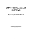
Expandable Smart Switch Model 232XSSD4 Document No. 232XSSD43800 This product designed and manufactured in Ottawa, Illinois USA of domestic and imported parts by International Headquarters B&B Electronics Mfg. Co. Inc. USA 707 Dayton Road - P.O. Box 1040 -- Ottawa, IL 61350 Phone (815) 433-5100 General Fax (815) 433-5105 -- Sales Fax (815) 433-5109 Technical Support Fax (815) 433-5104 Internet: www.bb-elec.com [email protected] [email protected] European Headquarters B&B Electronics Ltd. Westlink Commercial Park, Oranmore, Co. Galway, Ireland Phone: +353 91-92444 -- Fax: +353 91-92445 Internet: www.bb-europe.com 1997 B&B Electronics -- Revised October 2000 232XSSD43800 Manual Cover Page B&B Electronics -- PO Box 1040 -- Ottawa, IL 61350 PH (815) 433-5100 -- FAX (815) 433-5104 TABLE OF CONTENTS CHAPTER 1: HARDWARE ............................................................... 1 INTRODUCTION ....................................................................................... 1 SPECIFICATIONS ...................................................................................... 2 CHECKLIST.............................................................................................. 3 SERIAL DATA CONFIGURATION ............................................................... 3 PORT CONFIGURATION ............................................................................ 4 Master Port ....................................................................................... 4 RS-232 Configuration ............................................................................ 9 RS-422/485 Slave Port Option ........................................................... 10 RS-422/ RS-485 Mode ............................................................................ 11 PORT EXPANSION BUS .......................................................................... 13 SMART SWITCH OPERATION.................................................................. 13 Smart Switch Mode ....................................................................... 13 Three Character Command String ..................................................... 13 Four Character Command String ....................................................... 15 Programming the User Defined Character ....................................... 16 Smart Switch/Port Combiner Mode............................................. 17 BINARY FILE TRANSFER ....................................................................... 18 PORT SELECT TEST ............................................................................... 18 CHAPTER 2: SOFTWARE ............................................................. 19 INTRODUCTION ..................................................................................... 19 WINDOWS SELECTOR PROGRAM INSTALLATION/INSTRUCTIONS ........... 19 SMART SWITCH SETUP .......................................................................... 20 DEFAULT VALUES ................................................................................. 20 SELECTING PORTS ................................................................................. 21 PARAMETERS ........................................................................................ 21 UNINSTALLING WINDOWS SMART SWITCH SELECTOR PROGRAM ......... 21 DOS TSR INSTALLATION AND INSTRUCTIONS ...................................... 21 Parameters ..................................................................................... 24 Default Values................................................................................ 26 Help Screen.................................................................................... 26 Selecting Ports............................................................................... 26 Hot Key Method ............................................................................. 27 Command Line Method ................................................................ 27 Uninstalling the TSR ..................................................................... 28 232XSSD43800 Manual Table of Contents B&B Electronics -- PO Box 1040 -- Ottawa, IL 61350 PH (815) 433-5100 -- FAX (815) 433-5104 i APPENDIX A: ACSII CHARACTER CODES............................A-1 APPENDIX B: CABLE CHARTS................................................. B-1 CHART 1. IBM PC DB25 CONNECTOR TO MASTER PORT ................. B-1 CHART 2. IBM PC DB9 CONNECTOR TO MASTER PORT ................... B-1 CHART 3. MODEM DB25 CONNECTOR TO MASTER PORT ................. B-2 CHART 4. DCE DEVICE W/DB25 CONNECTOR TO PORTS A - H (DTE) ...................................................................................... B-2 CHART 5. IBM PC DB25 CONNECTOR TO PORTS A - H (DTE) ........ B-3 CHART 6. IBM PC DB9 CONNECTOR TO PORTS A - H (DTE) .......... B-3 CHART 7. IBM PC DB25 CONNECTOR TO PORTS A - H (DTE)......... B-4 CHART 8. IBM PC DB9 CONNECTOR TO PORTS A - H (DTE) .......... B-4 CHART 9. RS-422/485 4-WIRE DEVICE TO PORT (A - H) CONFIGURED AS AN RS-422 /485 PORT................................... B-5 CHART 10. RS-485 2-WIRE DEVICE TO PORT (A - H) CONFIGURED AS AN RS-485 PORT............................................................... B-5 ii Table of Contents 232XSSD43800 Manual B&B Electronics -- PO Box 1040 -- Ottawa, IL 61350 PH (815) 433-5100 -- FAX (815) 433-5104 Chapter 1: HARDWARE Introduction The RS-232 Eight Port Expandable Smart Switch (232XSSD4) allows one RS-232 host device to connect to eight asynchronous serial devices. Refer to Figure 1. Four RS-232 ports and four RS232 or RS-485 (two or four wire, send data contol) are standard on the 232XSSD4, depending on the pins you use. Other options and additional RS-422/485 ports are available by contacting B&B technical support. The 232XSSD4 can be easily expanded to add up to sixty additional ports for a total of sixty-eight ports by using the Model 232PE Port Expander. Ports configured as RS-232 support signals TD, RD, RTS, CTS, DTR, and DSR or CD. Refer to Figure 5. Ports configured as RS-422/485 support signals TD and RD only. Refer to Figure 6. The Master port is DTE or DCE configurable. RS-232 ports "A" through "H" are configured as DTE ports. The 232XSSD4 will switch with baud rates from 300 to 38,400 bps, 7 or 8 data bits, even, odd or no parity, and 1 or 2 stop bits. After the switch is made the 232XSSD4 is transparent to data flow. There are nine red indicator LED's on the front of the 232XSSD4. Eight LED's represent ports "A" through "H" and indicate the selected port. The ninth LED is the power on indicator. Ten connectors are located on the back of the 232XSSD4, a twenty pin expansion bus connector, a DB-25S female Master port connector, and eight DB-25P male connectors for ports "A" through "H". Refer to “Front View” diagram. Port selection is accomplished by sending a programmable control string to the "Master" port of the Expandable Smart Switch. This control string consists of a user-defined character, address character, and port character. When the 232XSSD4 receive the control string the "Master" port will be connected to the designated port. There is no delay through the 232XSSD4 and the data is not buffered. When the 232XSSD4 is set to Smart Switch Mode Port "A" will be selected at power up. The eight ports on the 232XSSD4 can also be used as a smart switch/port combiner. In addition to using the Master Port for port selection, any of the eight ports can select the Master Port by asserting their CTS line. This function is enabled by setting a switch inside the 232XSSD4. 232XSSD43800 Manual B&B Electronics -- PO Box 1040 -- Ottawa, IL 61350 PH (815) 433-5100 -- FAX (815) 433-5104 1 Specifications Model: 232XSSD4 Size: 10.1"w x 7.5"d x 3.3"h Power: 120VAC 60hz 16w Connectors: Master - DB-25 female (RS-232 or RS-422) Slave - DB-25 male (RS-232 or RS-422/485) Switching Baud Rate: from 300 to 38.4 Kbps Baud Rate: Any baud rate up to 115.2 Kbps Front View Rear View 2 232XSSD43800 Manual B&B Electronics -- PO Box 1040 -- Ottawa, IL 61350 PH (815) 433-5100 -- FAX (815) 433-5104 Switch Control Master Port TD UART Microcontroller Expansion Bus Port Combiner Control Lines Ports "A-H" T D Port A T D Port B T D Port C T D Port D T D Port E T D Port F T D Port G T D Port H C T S Port A C T S Port H Figure 1. Simplified Functional Diagram NOTE: This diagram illustrates only the transmit data (TD) signal. Checklist The following equipment should be in the shipping carton: 1. Expandable Smart Switch 2. Instruction Manual 3. (2) 3 1/2" disks If any of the items above are damaged or missing contact the shipper immediately. Serial Data Configuration In order for the host device, which is connected to the Master Port of the Smart Switch, to select a port, the Smart Switch must be set to match the host's communication format. This is accomplished by setting an eight position DIP switch labeled "SW1" located inside the Smart Switch. Refer to Figure 2. Switch positions 1 through 4 select the baud rate. Switch position 5 selects 7 or 8 data bits. Refer to Table 1. The remaining switch positions will be discussed later. Always power down the Smart Switch before changing switch settings. 232XSSD43800 Manual B&B Electronics -- PO Box 1040 -- Ottawa, IL 61350 PH (815) 433-5100 -- FAX (815) 433-5104 3 Table 1. Communication & Configuration Switch 1 0 1 0 1 0 1 0 1 X X X X X X X X DIP Switch 1 2 3 4 5 6 7 8 0 0 0 X X X 0 0 0 X X X 1 0 0 X X X 1 0 0 X X X 0 1 0 X X X 0 1 0 X X X 1 1 0 X X X 1 1 0 X X X X X X 0 X X X X X 1 X X X X X X 0 X X X X X 1 X X X X X X X X X X X X X X X X X X X X X 0 1 X X X X X X X X X X X X X X X X 0 1 Setting 300 Baud 600 Baud 1200 Baud 2400 Baud 4800 Baud 9600 Baud * 19.2K Baud 38.4K Baud 8 Data Bits * 7 Data Bits Smart Switch Mode * Smart Switch and Port Combiner Mode 3 Char. Command * 4 Char. Command Port Select Test Off * Port Select Test On 0 = OFF 1 = ON X = DON'T CARE * = FACTORY DEFAULT Port Configuration The 232XSSD4 has a Master port and eight selectable ports labeled "A" through "H". Refer to “Rear View”. The Master port should be connected to the RS-232 device that will be selecting the ports. Ports "A - H” connect to the RS-232 or RS-422/485 devices that will communicate with the Master port device. Master Port The Master port can be configured by the user as a DCE or a DTE port. In order to determine the proper Master port configuration of the 232XSSD4 it is necessary to have a basic understanding of the terms DCE and DTE. RS-232 was designed, using DB-25 connectors, for connecting a DTE (Data Terminal Equipment) device to a DCE (Data Communication Equipment) device. Each device will have inputs on pins that correspond to outputs on the same pins of the other device. For example, a DTE device transmits data out on pin 2 and a DCE device receives data in on pin 2. IBM PC's are DTE devices, modems are DCE devices. The Master port is shipped configured as a DCE port. 4 232XSSD43800 Manual B&B Electronics -- PO Box 1040 -- Ottawa, IL 61350 PH (815) 433-5100 -- FAX (815) 433-5104 Figure 2. Printed Circuit Board Outline 232XSSD43800 Manual B&B Electronics -- PO Box 1040 -- Ottawa, IL 61350 PH (815) 433-5100 -- FAX (815) 433-5104 5 Figure 3. Master Port DCE/DTE Jumpers Figure 4. PC Board Options for RS-485 If an IBM PC (DTE device) is connected to the 232XSSD4 Master port, the Master port should be configured as a DCE port. If a modem (DCE device) is connected to the Master port, it should be configured as a DTE port. Refer to cable charts in Appendix B. The Master port is configured as either a DCE port or a DTE port by moving jumpers JP1: 1 through JP1: 7. JP1 is located inside the Smart Switch. Refer to Figures 2 & 3. To configure the Master port as a DCE port, jumpers JP1: 1 through JP1: 7 must be moved to the DCE position. Refer to Table 2. To configure the Master port as a DTE port, jumpers JP1: 1 through JP1: 7 must be moved to the DTE position. Refer to Table 3. 6 232XSSD43800 Manual B&B Electronics -- PO Box 1040 -- Ottawa, IL 61350 PH (815) 433-5100 -- FAX (815) 433-5104 Table 2. DCE MASTER PORT CHART Signal Direction of DCE Master Port Pin # Signal Description 2 TD Transmit Data Input 3 RD Receive Data Output 4 RTS Request to Send Input 5 CTS Clear to Send Output 6* DSR Data Set Ready Output 7 SG Signal Ground <------> 8* CD Carrier Detect Output 20 DTR Data Term Ready Input 14** TD (B) Transmit + Output 15** TD (A) Transmit Output 16** RD (B) Receive + Input 17** RD (A) Receive Input * Pins 6 & 8 are tied together inside the 232XSSD4 and share the same output. Refer to Figure 5. ** 422 master port option. Important: All jumpers must be in the same position, either DCE or DTE positions. Do not mix positions! Refer to Figure 3 which shows the Master port configured as a DCE port. CAUTION: Always power down the Smart Switch before removing its cover. 232XSSD43800 Manual B&B Electronics -- PO Box 1040 -- Ottawa, IL 61350 PH (815) 433-5100 -- FAX (815) 433-5104 7 Table 3. DTE MASTER PORT CHART Pin # 2 3 4 5 Signal TD RD RTS CTS Description Transmit Data Receive Data Request to Send Clear to Send Signal Direction of DTE Master Port Output Input Output Input 6* DSR Data Set Ready Input 7 SG Signal Ground <------> 8* CD Carrier Detect Input 20 DTR Data Term Ready Output 14** TD (B) Transmit + Output 15** TD (A) Transmit Output 16** RD (B) Receive + Input 17** RD (A) Receive Input * Pins 6 & 8 are tied together inside the 232XSSD4 and share the same input. Refer to Figure 5. ** 422 master port option only 8 232XSSD43800 Manual B&B Electronics -- PO Box 1040 -- Ottawa, IL 61350 PH (815) 433-5100 -- FAX (815) 433-5104 Table 4. DTE PORTS A - H RS-232 Signal Direction of DTE Ports A Pin # Signal Description through H 2 TD Transmit Data Output 3 RD Receive Data Input 4 RTS Request to Send Output 5 CTS Clear to Send Input 6* DSR Data Set Ready Input 7 SG Signal Ground <------> 8* CD Carrier Detect Input 20 DTR Data Term Ready Output 14** TD(B) Transmit (+) Output 15** TD(A) Transmit (-) Output 16** RD(B) Receive (+) Input 17** RD(A) Receive (-) Input *Pins 6 & 8 are tied together inside the 232XSSD4 and share the same input. Refer to Figure 5. ** RS-422/485 option if installed The 232XSSD4 has eight ports labeled "A - H". Refer to “Rear View”. Any of these ports can be manufactured to meet either RS232 or RS-422/485 electrical characteristics. The 232XSSD4 comes standard with four RS-232 ports and four ports that are RS-232 or RS-485 depending on the pins that you use. RS-232 Configuration All eight RS-232 slave ports will be wired as DTE ports. Refer to Table 4 for pin out, signal name, and signal direction information. Also, refer to Figure 5 for a simplified schematic showing the relationship between the Master port and any RS-232 port "A-H". Refer to Appendix B for cable charts. 232XSSD43800 Manual B&B Electronics -- PO Box 1040 -- Ottawa, IL 61350 PH (815) 433-5100 -- FAX (815) 433-5104 9 Figure 5. Simplified RS-232 Schematic RS-422/485 Slave Port Option The RS-232 transmit and receive data signals on the Master port will be converted to balanced, full-duplex RS-422 or half-duplex RS-485 signals with this option. The 232XSSD4 comes standard with four RS-485 (2 or 4-wire) slave ports. Refer to Appendix B for cable charts. Table 5. RS-422/485 PORTS A - H 10 Pin # Signal Description 15 14 7 17 16 TD(A) TD(B) SG RD(A) RD(B) Transmit Data (-) Transmit Data (+) Signal Ground Receive Data (-) Receive Data (+) RS-422/485 Signal Direction of Ports A - H Output Output <------> Input Input 232XSSD43800 Manual B&B Electronics -- PO Box 1040 -- Ottawa, IL 61350 PH (815) 433-5100 -- FAX (815) 433-5104 Figure 6. Simplified RS-422/485 Schematic When a port has this option, additional circuitry will be mounted to the main board. The standard 232XSSD4 comes with the RS-485 option on four ports (Port A-D). Use Figure 2 to locate its position. Refer to Table 5 for pin-out, signal name, and signal direction information. Also, refer to Figure 6 for a simplified schematic showing the relationship between the Master port and a port configured with the RS-422/485 option. NOTE: This option only supports transmit and receive data signals (TD & RD) from the Master port. RS-422/ RS-485 Mode The model 232XSSD4 comes standard with an automatic send data (SD) control of the RS-485 driver. SD control automatically enables the RS-485 driver by sensing the leading edge of the first character transmitted from the device connected to the Master port. After the last character transmits, the send data timer circuit waits one character time (about 1 millisecond at 9600 baud) before disabling the RS-485 driver. 232XSSD43800 Manual B&B Electronics -- PO Box 1040 -- Ottawa, IL 61350 PH (815) 433-5100 -- FAX (815) 433-5104 11 There are two components located in the port B circuit area on the main printed circuit board, a resistor (R75) and a capacitor (C4), that are part of the send data control circuit. These components are factory selected for 9600 baud, which allows the send data control to operate at 9600 baud or higher. With these two components the RS-485 driver will be disabled approximately 1 millisecond after the last character has been sent. To change to a baud rate lower than 9600 baud, or to configure the send data control to match a specific baud rate, change R75 and C4 to the value specified in Table 6. Use Figure 3 to locate R75 and C4. Note that these timing components are not used when the handshake control method is selected. Table 6. Component Values For Send Data Timing Baud Rate 300 600 1200 2400 4800 9600 19200 38400 56700 115200 Time (ms) 33.3 16.6 8.33 4.16 2.08 1.04 0.520 0.260 0.176 0.0868 Resistor Value R75 (ohms) 330K 160K 820K 430K 200K 100K 56K 27K 16K 8.2K Capacitor Value C4(microfarads) .1 .1 0.01 0.01 0.01 0.01 0.01 0.01 0.01 0.01 To configure a port for RS-485 two-wire mode, both jumpers must be placed in the two-wire "2" position for the corresponding port Refer to Figure 4 for these jumper locations. The TD (A) and RD (A) lines need to be connected together; also the TD (B) and RD (B) lines need to be connected to each other. Giving you a Data (A) line and a Data (B) line. “A” being “+” and “B” being “-“. Handshake control (RTS) requires that the software use a handshake signal to enable/disable the RS-485 driver. The handshake signal RTS (pin 4) is used when the Master port is configured as a DCE port and CTS (pin 5) is used when the Master port is configured as a DTE port. If the RTS option is needed, contact B&B Technical Support for details. 12 232XSSD43800 Manual B&B Electronics -- PO Box 1040 -- Ottawa, IL 61350 PH (815) 433-5100 -- FAX (815) 433-5104 Another option available on the 232XSSD4 is the slave ports set up as RS-422 ports. This means that the driver and receiver will be enabled all the time. RS-422 allows point-to-point operation or up to 10 receive only units up to 4000 feet on two pair of lines. Port Expansion Bus The number of serial ports on the 232XSSD4 can easily be expanded to a maximum of sixty-eight ports. Fifteen Port Expander units (232PE) can be added to the 232XSSD4 by simply connecting the 232PE units to the Port Expansion Bus. Each Port Expander unit (232PE) adds four additional serial ports. The Port Expansion Bus connects each port to the electronic switch control circuit in the 232XSSD4. In order for the 232XSSD4 to select a port on a Port Expander unit, each unit must be assigned its own unique address from "1" to "15". These addresses are switch selectable by the user. Refer to the 232PE manual for more information. Smart Switch Operation The 232XSSD4 has two modes in which it can select ports, smart switch, and smart switch/port combiner. Smart Switch Mode Position 6 of SW1 must be in the off position to enable this mode. Refer to Figure 2 and Table 1. The Smart Switch is a listen only device. It constantly monitors the serial data received on the Master port for a command control string. A command can switch on or switch off any desired port. The command control string can be configured as a three-character command or a four-character command. In this mode Port "A" will be selected at power up. Three Character Command String The first character is user defined by setting SW2, an eightposition DIP switch. SW2 is programmed at the factory to the ASCII character STX (decimal 2). The second character represents the hexadecimal address of the Smart Switch where the desired port is located. The address for the 232XSSD4 is always zero (0). The address of the port expanders (232PE) can be from 1 through 15 (ASCII-HEX "1" through "F"). The third character is the ASCII upper case letter that represents the desired port. Letters "A", "B", "C", "D", "E", "F", "G" or "H" (decimal 65, 66, 67, 68, 69, 70, 71, or 72 respectively) are used to select ports on the 232XSSD4. Letters "A", "B", "C", or "D" (decimal 65, 66, 67, or 68 respectively) are used to select ports on the 232PE. 232XSSD43800 Manual B&B Electronics -- PO Box 1040 -- Ottawa, IL 61350 PH (815) 433-5100 -- FAX (815) 433-5104 13 Example 1: To turn on port E of the 232XSSD4 (address zero) with ASCII STX (2 decimal) character set as the user defined character. Send to the Master Port: STX 0 E (2 48 69 decimal) Example 2: To turn on port B located at port expander (232PE) address ten with ASCII STX (2 decimal) character set as the user defined character. Send to the Master Port: STX A B (2 65 66 decimal) When you are done with a port you can either select a new one directly or turn off the selected port and then turn on the next one. It is recommended that the selected port be turned off before selecting the next port. For this reason, if port A is currently selected and a command is sent to select port E, the command characters (STX 0 E) will pass through to the port A device and because characters "0" and "E" are printable they may appear on that device. To turn any selected port off, the first and second character of the command control string must be the user-defined character. The third character must be the ASCII EOT character (decimal 4). Example 3: To turn off all ports, with ASCII STX (decimal 2) set as the user defined character. Send to the Master Port: STX STX EOT (2 2 4 decimal) It is recommended that the user-defined character be a nonprintable character. The turn off command will then consist of three characters that will not show up on the current port device. If you were writing a program in GWBASIC to select port E of the 232XSSD4 (address zero) you would form a string like this: SW0E$ = CHR$(2) + "0" + "E" You could then send SW0E$ to select port E. Similar strings could be used for turning on the other ports. To turn off the ports the string might look like this: TOFF$ = CHR$(2) + CHR$(2) + CHR$(4) NOTE: There is no delay through Smart Switch; data is not buffered. 14 232XSSD43800 Manual B&B Electronics -- PO Box 1040 -- Ottawa, IL 61350 PH (815) 433-5100 -- FAX (815) 433-5104 Four Character Command String The four-character command adds additional security to port selection. The only difference between the four-character command and the three-character command is the addition of the ASCII ESCape character in front of the three-character command. The first character is the ASCII ESC character (decimal 27). The second character is user-defined character. The third character is the desired port address. The fourth character is the ASCII upper case letter of the desired port. Refer to the "Three Character Command String" section for more information regarding the last three characters. Example 1: To turn on port E of the 232XSSD4 (address zero) with ASCII STX set as the user defined character. Send to Master port: ESC STX 0 E (27 2 48 69 decimal) Example 2: To turn on port B located at port expander (232PE) address ten with ASCII STX set as the user defined character. Send to Master Port: ESC STX A B (27 2 65 66 decimal) The turn off string also adds the ASCII ESC character to the front of the three-character turn off string. The first character is the ASCII ESC character. The second and third character of the command control string is the user-defined character. The fourth character is the ASCII EOT character (decimal 4). Example 3: To turn off all ports and the user defined character is ASCII STX (decimal 2). Send to Master Port: ESC STX STX EOT (27 2 2 4 decimal) It is recommended that the user-defined character be a nonprintable character. The turn off command will then consist of four characters that will not show up on the current port device. 232XSSD43800 Manual B&B Electronics -- PO Box 1040 -- Ottawa, IL 61350 PH (815) 433-5100 -- FAX (815) 433-5104 15 If you were writing a program in GWBASIC to select port E of the 232XSSD4 (address zero) you would form a string like this: SW0E$ = CHR$(27) + CHR$(2) + "0" + "E" You could then send SW0E$ to select port E. Similar strings could be used for turning on the other ports. To turn off the ports the string might look like this: TOFF$ = CHR$(27) + CHR$(2) + CHR$(2) + CHR$(4) NOTE: There is no delay through the Smart Switch and the data is not buffered. Programming the User Defined Character The user-defined character comes programmed as the ASCII STX character (decimal 2). You can change this to any 8-bit character you wish by reprogramming DIP switch 2 (SW2). SW2 is located on the printed circuit board inside the 232XSSD4. Refer to Figure 2. SW2 is an eight-position switch with each position equal to a certain weight. Refer to Table 4. It is recommended that a nonprintable character be defined. Table 4. SW2 WEIGHT CHART DIP Switch 2 WEIGHT 1 1 2 2 3 4 4 8 5 16 6 32 7 64 8 128 For example, if you wish to use the ASCII NAK character as the user defined character, which has a decimal value of 21, you would turn on switches 1, 3, and 5 (1 + 4 + 16 = 21). Caution should be used when selecting the user defined character, so that by itself, or with the ESC character in front of it (4-character command), or with the character following it, it is not a valid command to any of the devices connected to the ports. For instance, on some printers ESC @ is the reset command. If you tried to use the @ symbol (decimal 64) for the user defined character you could reset your printer every 16 232XSSD43800 Manual B&B Electronics -- PO Box 1040 -- Ottawa, IL 61350 PH (815) 433-5100 -- FAX (815) 433-5104 time the command control string is sent. Note also, that if your communication configuration is set for 7 data bits you cannot use the eighth position of SW2. For a list of the ASCII character codes and their decimal values refer to Appendix A. Smart Switch/Port Combiner Mode This mode allows the CTS lines of ports A - H of the 232XSSD4 to select the Master port. It also allows selection from the Master port via the command control string described in the Smart Switch Mode section. Position 6 of DIP switch 1 (SW1) must be in the ON position to enable this mode. Refer to Figure 2. When all ports are off and the CTS line (pin 5) goes high on any of the eight ports, a connection is established from that port to the Master port. This works on a first-come-first-serve basis and only for RS-232 configured ports. At power up in this mode there is no port selected. For example, if port A of the 232XSSD4 wanted to established a connection to the Master port, port A would raise its CTS line (pin 5) high. The 232XSSD4 would recognize this as a prompt for connection to the Master port. The connection would be dropped as soon as the CTS line on port A was lowered. At that time any of the other RS-232 ports on the 232XSSD4 can raise their CTS line to establish connection. If port A is connected to the Master port and any of the other RS-232 ports on the 232XSSD4 raises their CTS line, the data sent to the 232XSSD4 from those ports would be lost. The 232XSSD4 does not have buffering. Note that when a port is selected via the Master port, the CTS lines will be ignored until the Smart Switch receives the turn off command from the Master port. When a CTS line selects the Master port, all commands will be ignored until CTS goes low. A typical application would be to tie CTS & RTS together on the Master port. So when CTS on a port is raised, RTS on that port also goes high establishing a connection for your hardware. Note that RTS will be low until connection to the Master port has been completed. The other ports will be held off because TD, RTS, and DTR will be low. After CTS goes low, the 232XSSD4 will scan the CTS lines starting with the next port. When there are no ports selected Port A will have first priority, port B second and so on. NOTE: The port combiner function is not available on the Port Expander units. 232XSSD43800 Manual B&B Electronics -- PO Box 1040 -- Ottawa, IL 61350 PH (815) 433-5100 -- FAX (815) 433-5104 17 Binary File Transfer A simple method of using the Smart Switch to transfer binary files without the concern of it accidentally disconnecting, is to set the file transfer at a baud rate different from the baud rate of the Smart Switch. When transferring files at a different baud rate, the Smart Switch will stay connected from the last command control string. Port Select Test The 232XSSD4 has a built-in port select test. Placing DIP switch 1 (SW1) position 8 in the on position and powering up the 232XSSD4 starts this test. Refer to Figure 2. It will test the port selection, port expansion, and address circuits for all sixty-eight ports. When the test is started each port will be individually turned on for one second, starting with port A on the 232XSSD4 and ending with port D at address fifteen for a total test time of sixty-eight seconds. Once the last port has been turned off the test will start over and continue looping until SW1 position 8 is placed in the off position, at which time the Smart Switch will begin normal operation. This test is can be used to verify address settings of the port expander modules. 18 232XSSD43800 Manual B&B Electronics -- PO Box 1040 -- Ottawa, IL 61350 PH (815) 433-5100 -- FAX (815) 433-5104 Chapter 2: SOFTWARE Introduction The Expandable Smart Switch Selector program for Windows allows the user to select ports in the windows environment. The SS program requires 2M of memory. The Expandable Smart Switch, Terminate and Stay Resident (XSSTSR) Program (IBM PC or Compatible), allows the user to change Smart Switch ports either through the command line or by hitting a sequence of keys at the same time, referred to as hot keys. The XSSTSR requires 1K of memory. Windows Selector Program Installation/Instructions Method One • Place the “Windows” disk in drive A. • Select Settings from the Start Button and click on Control Panel. • In the Control Panel Window, double click on the Add/Remove Programs. • Click on the “Install” button. • Follow the instructions of the setup program. Method Two • Place the “Windows” disk in drive A. • Select Programs from the Start Button and click on Windows Explorer. • Click on the drive containing the SS Setup Disk. • Double click on the file “Setup.exe”. • Follow the instructions of the setup program. 232XSSD43800 Manual B&B Electronics -- PO Box 1040 -- Ottawa, IL 61350 PH (815) 433-5100 -- FAX (815) 433-5104 19 Description Port Address Baud Rate Data Bits Second Character Default Value COM 1 9600 8 Data Bits 2 = STX (CTRL B) The following files will be located on your hard drive: • SS.EXE - The executable file for the Smart Switch. • FILES.LST Contains a list and description of files installed on your hard drive. • READ.ME Contains corrections and additions to the printed users manual. • HISTORY.LST Contains a historic description of the product. • BBWSC16.DLL, BC500RTC.DLL, BDS501.DLL, OWL501.DLL Dynamic link libraries required for proper operation of program. Smart Switch Setup The Smart Switch program will prompt the user for the Module that is in use the first time that the software is run. After the proper Module (i.e. PortMUX, 232XS5,etc.) is selected then a window specific to that Module will appear and the user may personalize communication parameters as per their specific needs. Comport, Baud Rate, and Data Bits (Character Mode, and User Defined Character may also be set for 232XSS and 232XS5 Modules). Should the user wish to change the Module choice to another there is a Module menu choice with the three support Module types (PortMUX, 232XSS, and 232XS5). After changing the Module the user will be prompted to restart the Smart Switch software to reset the connection. Default Values When you start Smart Switch software, the default values will be used. The default values are: 20 232XSSD43800 Manual B&B Electronics -- PO Box 1040 -- Ottawa, IL 61350 PH (815) 433-5100 -- FAX (815) 433-5104 Selecting Ports To select a port the user need only pick from the Menu-> Comport the comport to which the device is attached. The Smart Switch program supports comports 1 through 6. If the port exists but does not have a smart switch device attached, SS will not detect it. The SS software will only detect invalid/undefined comports. Parameters The Port Address is the address where the serial communications port is located. If this is unknown you can use the program PORTFIND.EXE which is located on the disk. To use PORTFIND.EXE: If you installed the software on your hard drive (see the Installation section): • Type C: and press the ENTER key. • Type CD\SS\UTIL and press the ENTER key. • Type PORTFIND and press the ENTER key. Uninstalling Windows Smart Switch Selector Program • Go to “Control Panel” and click on “Add/Remove Programs” • Click on “Smart Switch” and the click “Remove” • Windows will then “Automatically” remove the program from your system DOS TSR Installation and Instructions The software for the XSSTSR can be run from a floppy drive or from the hard drive. There are two methods to begin the XSSTSR program. The first and preferred way is to use the SETUP.EXE program and the second is through the XSSTSR.COM file. 232XSSD43800 Manual B&B Electronics -- PO Box 1040 -- Ottawa, IL 61350 PH (815) 433-5100 -- FAX (815) 433-5104 21 1) SETUP.EXE Method (preferred) If the software was installed on your hard drive follow these steps: • Type C: and press the ENTER key. • Type CD\XSS and press the ENTER key. Or if you are going to execute SETUP.EXE from the floppy drive follow these steps: • Place the “DOS” disk in drive A. • Type A: and press the ENTER key. To begin the XSSTSR program follow these steps: • Type SETUP and press the ENTER key. You will be prompted for parameters (for descriptions refer to the Parameters section) that are necessary for the XSSTSR to communicate with the Smart Switch. The values in [ ] are the default values. If this value is desired, just press the ENTER key. Enter Port Address [02F8]: Enter Baud Rate ( 1 = 150 2 = 300 3 = 600 4 = 1200 5 = 2400 6 = 4800 7 = 9600 8 = 19200 9 = 38400) [7]: Enter Parity (0 = No 1 = Odd 2 = Even) [0]: Enter Number of Data Bits 7 = Seven Data Bits 8 = Eight Data Bits) [8]: Enter Smart Switch User Defined Char (Decimal Value) [2]: Enter Three Character or Four Character Command String (0 = 3 Char. 1 = 4 Char.) [0]: 22 232XSSD43800 Manual B&B Electronics -- PO Box 1040 -- Ottawa, IL 61350 PH (815) 433-5100 -- FAX (815) 433-5104 Enter Hot Key Sequence ( 1 = <Lft Shift><Alt><A|B|C|D|E|F|G|H|N> 2 = <Rht Shift><Alt><A|B|C|D|E|F|G|H|N> 3 = <Lft Shift><Alt><1|2|3|4|5|6|7|8|N> 4 = <Rht Shift><Alt><1|2|3|4|5|6|7|8|N> 5 = <CTRL><ALT><A|B|C|D|E|F|G|H|N> 6 =<CTRL><ALT><1|2|3|4|5|6|7|8|N>)[1]: At this point, a file called GO.BAT will be created. • Type GO and press the ENTER key. Once the GO.BAT file is created, every time you wish to begin the XSSTSR all that you need to do is type GO and press the ENTER key. If you need to change any of the settings of the XSSTSR simply run the SETUP.EXE program again to create a new GO.BAT file. 2) XSSTSR.COM Method The XSSTSR.COM method requires the same parameters (for descriptions refer to the Parameters section) as the SETUP.EXE method, except that they are all specified through the command line. Each of these parameters begins with a command symbol followed by an option as defined in the following table. Command Description A or a Port Address Options Hexadecimal Address (0 - FFFFh) B or b Baud Rate 1 = 150 2 = 300 3 = 600 4 = 1200 5 = 2400 6 = 4800 7 = 9600 8 = 19200 9 = 38400 D or d Number of Data Bits 7 = 7 Data Bits 8 = 8 Data Bits P or p Parity 0 = No U or u User Defined Char. Decimal (0 - 255) C or c Command String 0 = 3 Character H or h Hot Key 1 = <Left Shift><ALT><A|B|C|D|E|F|G|H|N> 2 = <Right Shift><ALT><A|B|C|D|E|F|G|H|N> 3 = <Left Shift><ALT><1|2|3|4|5|6|7|8|N> 4 = <Right Shift><ALT><1|2|3|4|5|6|7|8|N> 5 = <CTRL><ALT><A|B|C|D|E|F|G|H|N> 6 = <CTRL><ALT><1|2|3|4|5|6|7|8|N> 1 = Odd 2 = Even 1 = 4 Character 232XSSD43800 Manual B&B Electronics -- PO Box 1040 -- Ottawa, IL 61350 PH (815) 433-5100 -- FAX (815) 433-5104 23 If the software was installed on your hard drive follow these steps: • Type C: and press the ENTER key. • Type CD\XSS and press the ENTER key. Or if you are going to execute XSSTSR.COM from the floppy drive follow these steps: • Place the “DOS” disk in drive A. • Type A: and press the ENTER key. To begin the XSSTSR program (the following will be used as an example): Port Address = 03F8 Parity = Odd Baud = 9600 User Defined Char. = 8 Data Bits = 8 Command String = 0 Hot Key Sequence = 4 • Type XSSTSR A03F8 B7 D8 P1 U8 C0 H4 and press the ENTER key. Using this method, every time you want to install the XSSTSR with different parameter settings than the default (refer to the Default Values section), the missing parameter must be specified. Parameters The Port Address is the address where the serial communications port is located. If this is unknown you can use the program PORTFIND.EXE which is located on the disk. To use PORTFIND.EXE: If you installed the software on your hard drive (see the Installation section): • Type C: and press the ENTER key. • Type CD\XSS and press the ENTER key. • Type PORTFIND and press the ENTER key. 24 232XSSD43800 Manual B&B Electronics -- PO Box 1040 -- Ottawa, IL 61350 PH (815) 433-5100 -- FAX (815) 433-5104 If you are running from the floppy drive: • Place the “DOS” disk in drive A. • Type A: and press the ENTER key. • Type PORTFIND and press the ENTER key. The result will be similar to the following: PortFind V1.03 - © 1991 B&B Electronics - All Rights Reserved. Slave 8259 present can't use shared IRQ2 COM1 at address 03F8h is set for IRQ4 and is a 8250A or 16450 type UART COM2 at address 02F8h is set for IRQ3 and is a 8250A or 16450 type UART LPT1 at address 0378h found Some of the typical port addresses are as follows: Port COM 1 COM 2 COM 3 COM 4 Address 03F8h 02F8h 03E8h 02E8h The Baud Rate is the speed at which communication takes place between the XSSTSR and the Smart Switch. It must be specified so that it is equal to SW1 on the Smart Switch. The Number of Data Bits is the length of each character that gets sent from the XSSTSR to the Smart Switch. This value must be specified so that it is equal to SW1 on the Smart Switch. The Parity is a method of error detection that takes place during the transmission of data between the XSSTSR and the Smart Switch. This value must be specified so that it is equal to SW1 on the Smart Switch. The User Defined Character must be set so that it is equal to SW2 on the Smart Switch. The Command String of the 232XSSD4 can be set to respond to a three character or four character command. For more information on this feature refer to the Smart Switch Operation section of this manual. 232XSSD43800 Manual B&B Electronics -- PO Box 1040 -- Ottawa, IL 61350 PH (815) 433-5100 -- FAX (815) 433-5104 25 The Hot Key is a sequence of three keys that must be pressed simultaneously to switch from one Smart Switch Port to another. For example, the hot key sequence, <Left Shift> <ALT> <A|B|C|D|E|F|G|H|N> states that the left shift, Alt, and either A, B, C, D, E, F, G, H, or N must be pressed at the same time to select the corresponding Smart Switch Port. N turns off all Smart Switch ports. Then press the Address Character where the desired port is located. This character is represented by a hexadecimal number from "0 to 9" and "A to F". The address for the 232XSSD4 is always zero (0) and the 232PEs can be set from 1 through 15 (1 to 9 and A to F). The Address Character is not required when turning off ports. Default Values If you type XSSTSR on the command line with no parameters, or omit any parameters, the default value of the missing parameter will be used. The default values are: Description Port Address Baud Rate Parity Data Bits User Defined Char. Command String Hot Key Sequence Default Value 02F8h (COM 2) 7 = 9600 0 = No Parity 8 = 8 Data Bits 2 = STX (CTRL B) 0 = 3 Character 1 = <Left Shift><ALT><A|B|C|D|E|F|G|H|N> Help Screen If you are installing the XSSTSR using the XSSTSR.COM method, you can type XSSTSR? and press the ENTER key to obtain a list of the commands and their options. Selecting Ports There are two different ways in which a Smart Switch port is selected: either through the command line or by pressing the predefined hot key sequence after the XSSTSR was installed. When a request to change ports is made, using either method, first the current port is turned off, and then the port selected is turned on. The two methods are described as follows: 26 232XSSD43800 Manual B&B Electronics -- PO Box 1040 -- Ottawa, IL 61350 PH (815) 433-5100 -- FAX (815) 433-5104 Hot Key Method This method enables the user to select any Smart Switch port by pressing a pre-defined sequence of keys at the same time after the XSSTSR is installed (refer to Program Installation section). Example: If Hot Key sequence <Lft Shift><Alt><A|B|C|D|E|F|G|H|N> was selected, to change ports you would press at the same time: Left Shift - Alt - A...… to select port A Left Shift - Alt - B ..... to select port B Left Shift - Alt - C ..... to select port C Left Shift - Alt - D ..... to select port D Left Shift - Alt - E ..... to select port E Left Shift - Alt - F ..... to select port F Left Shift - Alt - G ..... to select port G Left Shift - Alt - H ..... to select port H Left Shift - Alt - N ..... to turn off all ports Then press the address character to indicate the location of the desired port. This character is not required when turning ports off. Command Line Method This method enables the user to select any Smart Switch port through the command line. To specify a Smart Switch port through the command line, you would type XSSTSR followed by the X command symbol and the letter of the port. 232XSSD43800 Manual B&B Electronics -- PO Box 1040 -- Ottawa, IL 61350 PH (815) 433-5100 -- FAX (815) 433-5104 27 Example 1: To turn on port "C" of the 232XSSD4 you would type XSSTSR XC0 at the command line and press the ENTER key. Example 2: To turn on port "A" of a 232PE set to address 9 you would type XSSTSR XA9 at the command line and press the ENTER key. Before a smart switch port is selected, a check is made to determine if the communication port of the computer is busy transmitting. If the communication port is busy a tone will be generated to notify you that the port is busy and that a port selection cannot be made. CAUTION: If the software package you are using for transmission is running at a fast baud rate (115200), the XSSTSR may not detect the Smart Switch port as busy and the transmission could be interrupted. The XSSTSR does not detect when the 232XSSD4 port is receiving data. Therefore, if data is being received, the Smart Switch port may still be changed. Uninstalling the TSR The XSSTSR may be un-installed easily by typing XSSTSR and pressing the ENTER key. In some cases the XSSTSR will not un-install. This may be caused by another terminate and stay resident (TSR) being installed after it. To un-install the XSSTSR when this occurs, the other TSR must first be un-installed, and then the XSSTSR can be un-installed normally. 28 232XSSD43800 Manual B&B Electronics -- PO Box 1040 -- Ottawa, IL 61350 PH (815) 433-5100 -- FAX (815) 433-5104 APPENDIX A: ACSII Character Codes DECIMAL to HEX to ASCII CONVERSION TABLE DEC HEX ASCII KEY DEC HEX ASCII DEC HEX ASCII DEC HEX ASCII 0 NUL ctrl @ 32 20 SP 64 40 @ 96 60 ` 1 1 SOH ctrl A 33 21 ! 65 41 A 97 61 a 2 2 STX ctrl B 34 22 ] 66 42 B 98 62 b 3 3 ETX ctrl C 35 23 # 67 43 C 99 63 c 4 4 EOT ctrl D 36 24 $ 68 44 D 100 64 d 5 5 ENQ ctrl E 37 25 % 69 45 E 101 65 e 6 6 ACK ctrl F 38 26 & 70 46 F 102 66 f 7 7 BEL ctrl G 39 27 ' 71 47 G 103 67 g 8 8 BS ctrl H 40 28 ( 72 48 H 104 68 h 9 9 HT ctrl I 41 29 ) 73 49 I 105 69 i 10 A LF ctrl J 42 2A * 74 4A J 106 6A j 11 B VT ctrl K 43 2B + 75 4B K 107 6B k 12 C FF ctrl L 44 2C , 76 4C L 108 6C l 13 D CR ctrl M 45 2D - 77 4D M 109 6D m 14 E SO ctrl N 46 2E . 78 4E N 110 6E n 15 F SI ctrl O 47 2F / 79 4F O 111 6F o 16 10 DLE ctrl P 48 30 0 80 50 P 112 70 p 17 11 DC1 ctrl Q 49 31 1 81 51 Q 113 71 q 18 12 DC2 ctrl R 50 32 2 82 52 R 114 72 r 19 13 DC3 ctrl S 51 33 3 83 53 S 115 73 s 20 14 DC4 ctrl T 52 34 4 84 54 T 116 74 t 21 15 NAK ctrl U 53 35 5 85 55 U 117 75 u 22 16 SYN ctrl V 54 36 6 86 56 V 118 76 v 23 17 ETB ctrl W 55 37 7 87 57 W 119 77 w 24 18 CAN ctrl X 56 38 8 88 58 X 120 78 x 25 19 EM ctrl Y 57 39 9 89 59 Y 121 79 y 26 1A SUB ctrl Z 58 3A : 90 5A Z 122 7A z 27 1B ESC ctrl [ 59 3B ; 91 5B [ 123 7B { 28 1C FS ctrl \ 60 3C < 92 5C \ 124 7C | 29 1D GS ctrl ] 61 3D = 93 5D ] 125 7D } 30 1E RS ctrl ^ 62 3E > 94 5E ^ 126 7E ~ 31 1F US ctrl _ 63 3F ? 95 5F _ 127 7F DEL 232XSSD43800 Manual Appendix A B&B Electronics -- PO Box 1040 -- Ottawa, IL 61350 PH (815) 433-5100 -- FAX (815) 433-5104 A-1 APPENDIX B: Cable Charts These charts indicate some common cable wiring based on the DCE/DTE configuration of the Master Port. Refer to the Port Configuration section of this manual for information on Master Port configurations. Chart 1. IBM PC DB25 Connector to Master Port Master port configured as a DCE port. IBM PC 232XSSD4 Serial Port Signal Master Port (DCE) DB25 Connector Direction DB25 Connector 2 -----------> 2 3 <----------3 4 -----------> 4 5 <----------5 6 <----------6* 7 <---------> 7 8 <----------8* 20 -----------> 20 * Pins 6 & 8 are tied together inside the 232XSSD4 and share the same output. Chart 2. IBM PC DB9 Connector to Master Port Master port configured as a DCE port. IBM PC 232XSSD4 Serial Port Signal Master Port (DCE) DB9 Connector Direction DB25 Connector 1 <----------8* 2 <----------3 3 -----------> 2 4 -----------> 20 5 <---------> 7 6 <----------6* 7 -----------> 4 8 <----------5 * Pins 6 & 8 are tied together inside the 232XSSD4 and share the same output. 232XSSD43800 Manual B&B Electronics -- PO Box 1040 -- Ottawa, IL 61350 PH (815) 433-5100 -- FAX (815) 433-5104 B-1 Chart 3. Modem DB25 Connector to Master Port Master port configured as a DTE port. Async Modem 232XSSD4 Serial Port Signal Master Port (DTE) DB25 Connector Direction DB25 Connector 2 <----------2 3 -----------> 3 4 <----------4 5 -----------> 5 7 <---------> 7 8 -----------> 8* 20 <----------20 * Pins 6 & 8 are tied together inside the 232XSSD4 and share the same input. NOTE: When using chart 3 above and connecting a DTE device to ports A - H of the smart switch, refer to Charts 7 and 8. Chart 4. DCE Device w/DB25 Connector to Ports A - H (DTE) Master port configured as a DCE port. DCE Device 232XSSD4 Serial Port Signal Ports A - H (DTE) DB25 Connector Direction DB25 Connector 2 <----------2 3 -----------> 3 4 <----------4 5 ----------> 5 6 ----------> 6* 7 <---------> 7 8 -----------> 8* 20 <----------20 * Pins 6 & 8 are tied together inside the 232XSSD4 and share the same input. B-2 232XSSD43800 Manual B&B Electronics -- PO Box 1040 -- Ottawa, IL 61350 PH (815) 433-5100 -- FAX (815) 433-5104 Chart 5. IBM PC DB25 Connector to Ports A - H (DTE) Master port configured as a DCE port. IBM PC 232XSSD4 Serial Port Signal Ports A - H (DTE) DB25 Connector Direction DB25 Connector 2 -----------> 3 3 <----------2 4 -----------> 5 5 <---------4 6 <---------6* 7 <---------> 7 8 <----------8* 20 -----------> 20 * Pins are tied together inside the 232XSSD4 and share the same input. Chart 6. IBM PC DB9 Connector to Ports A - H (DTE) Master port configured as a DCE port. IBM PC 232XSSD4 Serial Port Signal Ports A - H (DTE) DB9 Connector Direction DB25 Connector 2 <----------2 3 -----------> 3 4 -----------> 6* 5 <---------> 7 6 <----------20 7 -----------> 5 8 <----------4 * Pins 6 & 8 are tied together inside the 232XSSD4 and share the same input. 232XSSD43800 Manual B&B Electronics -- PO Box 1040 -- Ottawa, IL 61350 PH (815) 433-5100 -- FAX (815) 433-5104 B-3 Chart 7. IBM PC DB25 Connector to Ports A - H (DTE) Master port configured as a DTE port with a modem connected (see Chart 3). IBM PC 232XSSD4 Serial Port Signal Ports A - H (DTE) DB25 Connector Direction DB25 Connector 2 -----------> 3 3 <----------2 4 -----------> 5 5 <----------4 6 <---- ----> 6* 7 <---------> 7 8 <----------20 20 -----------> 6* * Pins 6 & 8 are tied together inside the 232XSSD4 and share the same input. Chart 8. IBM PC DB9 Connector to Ports A - H (DTE) Master port configured as a DTE port with a modem connected (see Chart 3). IBM PC 232XSSD4 Serial Port Signal Ports A - H (DTE) DB9 Connector Direction DB25 Connector 3 -----------> 3 2 <----------2 7 -----------> 5 8 <----------4 6 <---- ----> 6* 5 <---------> 7 1 <----------20 4 -----------> 6* * Pins 6 & 8 are tied together inside the 232XSSD4 and share the same input. B-4 232XSSD43800 Manual B&B Electronics -- PO Box 1040 -- Ottawa, IL 61350 PH (815) 433-5100 -- FAX (815) 433-5104 Chart 9. RS-422/485 4-Wire Device to Port (A - H) Configured as an RS-422 /485 Port. RS-422/485 232XSSD4 4-Wire Signal Ports A - H Device Direction DB25 Connector TD (A)* -----------> 17 - RD (A) TD (B)* -----------> 16 - RD (B) Signal Ground <----------> 7 - SG RD (A)* <----------15 - TD (A) RD (B)* <----------14 - TD (B) * If the device being connected uses "+" and "-" in place of "B" and "A", the "+" replaces the "B" and the "-" replaces the "A". NOTE: Make sure the port's set-up jumpers are in the proper position for four-wire communications. Chart 10. RS-485 2-Wire Device to Port (A - H) Configured as an RS-485 Port. • • RS-485 232XSSD4 2-Wire Signal Ports A - H Device Direction DB25 Connector Data (A)* <----------> 15 - TD (A) Data (B)* <----------> 14 -TD (B) Signal Ground <----------> 7 - SG If the device being connected uses "+" and "-" in place of "B" and "A", the "+" replaces the "B" and the "-" replaces the "A". Place a jumper between the TD (A) and the RD (A) to make the Data (A) line. Also place a jumper between TD (B) and RD (B) to make the Data (B) line. NOTE: Make sure the port's set-up jumpers are in the proper position for two-wire communications. 232XSSD43800 Manual B&B Electronics -- PO Box 1040 -- Ottawa, IL 61350 PH (815) 433-5100 -- FAX (815) 433-5104 B-5 FEDERAL COMMUNICATIONS COMMISSION RADIO FREQUENCY INTERFACE STATEMENT Class A Equipment This equipment has been tested and found to comply with the limits for Class A digital device, pursuant to Part 15 of the FCC Rules. These limits are designed to provide reasonable protection against harmful interference when the equipment is operated in a commercial environment. This equipment generates, uses, and can radiate radio frequency energy and, if not installed and used in accordance with the instructions, may cause harmful interference to radio communications. Operation of this equipment in a residential area is likely to cause harmful interference, in which case the user will be required to correct the interference at personal expense. FCC Class A Equipment Statement