1
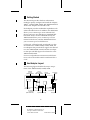
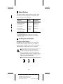
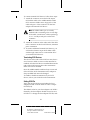
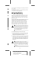
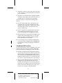
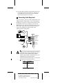
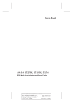
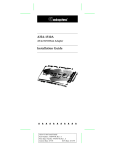
Installation Guide
AMM-1525M/1510M/525M
SCSI Audio Host Adapters and Sound Cards
R
AA
AAAA
AA
AAAAAAAA
AAAAAAAA
AAAAAAAA
AAAAAAAA
AAAAAAAA
AAAAAAAA
AAAAAAAA
AAAAAAAA
AAAAAAAA
AAAAAAAA
AAAAAAAA
AAAAAAAA
AAAAAA
AA
AA
AA
AMM-1525M/1510M/525M Installation Guide
AA
AA
AA
AA
AA
AA
Part
Number:
510659-00,
Rev.
A
AA
AA
AA
AA
AA
AA
Print
Spec
Number:
492931-00
AA
AA
AA
AA
AA
AA
Current
Date:
9/19/94
ECN
Date:
9/27/94
AA
AA
AAAAAAAAAAAAAAAAAAAAAAAAAAAAAAAAAAAAAAAAAAAAAAAAAAAAAAA
AA
1 Getting Started
This document provides the basic information
needed to quickly configure and install the Adaptec
AMM™-1525M, AMM-1510M, and AMM-525M SCSI
Audio Host Adapters and Sound Cards.
Each adapter provides multimedia capabilities with
advanced audio features. In addition, the AMM-1525
allows you to connect up to seven internal SCSI
devices, and up to two IDE devices (standard IDE
hard disks and/or ATAPI CD-ROM drives); the
AMM-1510M allows you to connect up to seven
internal SCSI devices; and the AMM-525M allows
you to connect up to two IDE devices.
Collectively, all three boards are referred to in this
document as the AMM-1525M/1510M/525M; the
two adapters that provide SCSI support are referred
to as the AMM-1525M/1510M; and the two adapters that provide IDE support are referred to as the
AMM-1525M/525M.
For more comprehensive instructions and illustrations, refer to the AMM-1525M/1510M/525M User’s
Guide.
2 Host Adapter Layout
The following figure identifies the major components of the AMM-1525M/1510M/525M.
IDE/ATAPI
Connector
(AMM-1525M/525M)
Internal
SCSI Connector
(AMM-1525M/1510M)
CD Audio
Input Connector
Headphones/
Speakers
J3
J4
Line Out
Line In
J9
Wavetable ROM
AIC-6360 SCSI
Protocol Chip
(AMM-1525M/1510M)
Bus Interface Chip
Sound Chip
J10 (AMM-1525M/1510M)
Game/MIDI Port
Microphone
1
A
AAAA
AAAA
AAAA
A
AAAAAAAA
AAAAAAAA
AAAAAAAA
AAAAAAAA
AAAAAAAA
AAAAAAAA
AAAAAAAA
AAAAAAAA
AAAAAAAA
AAAAAAAA
AAAAAAAA
AAAAAA
AA
A
AA
AMM-1525M/1510M/525M Installation Guide
A
AA
A
AA
A
AA
Part
Number:
510659-00,
Rev.
A
A
AA
A
AA
A
AA
Print
Spec
Number:
492931-00
A
AA
A
AA
A
AA
Current
Date:
9/19/94
ECN
Date:
9/27/94
A
AA
A
AAAAAAAAAAAAAAAAAAAAAAAAAAAAAAAAAAAAAAAAAAAAAAAAAAAAAA
AA
3 Default Settings
The AMM-1525M/1510M/525M is already configured for use with the majority of computers. The
default settings are listed below:
Description
Default
Setting
Sound Chip Base Address
220h
Jumper Block J9
Interrupt Channel (IRQ)1
11
Jumper Block J10
I/O Port Address1
340h
Jumper Block J10
IDE Port Address2
Secondary
(170h - 177h)
Jumper Block J4
IDE Port Enable2
Enabled
Jumper Block J4
Host Adapter Termination1
Enabled3
Host Adapter SCSI ID1
7
Configured By
—
aspi2dos.sys4
1
For AMM-1525M/1510M only.
2 For AMM-1525M/525M only.
3
Host adapter termination is always enabled and cannot be changed.
4
Configured through the aspi2dos.sys command line; see your Adaptec
EZ-SCSI User’s Guide.
4 Installing the Host Adapter
Changing Jumper Settings
In most cases, you will never have to change the
default jumper settings; however, if you need to
change jumper settings, do it before you install the
AMM-1525M/1510M/525M in your computer.
Note: Installing a jumper (On) means to
install a small plastic jumper connector so
that it covers both pins of the jumper pin
pair. Removing the jumper connector or having it cover only one pin is the same as having no jumper installed (Off).
On
Off
Off
2
A
AAAA
AAAA
AAAA
A
AAAAAAAA
AAAAAAAA
AAAAAAAA
AAAAAAAA
AAAAAAAA
AAAAAAAA
AAAAAAAA
AAAAAAAA
AAAAAAAA
AAAAAAAA
AAAAAAAA
AAAAAA
AA
A
AA
AMM-1525M/1510M/525M Installation Guide
A
AA
A
AA
A
AA
Part
Number:
510659-00,
Rev.
A
A
AA
A
AA
A
AA
Print
Spec
Number:
492931-00
A
AA
A
AA
A
AA
Current
Date:
9/19/94
ECN
Date:
9/27/94
A
AA
A
AAAAAAAAAAAAAAAAAAAAAAAAAAAAAAAAAAAAAAAAAAAAAAAAAAAAAA
AA
IRQ Channel and I/O Port Address (AMM-1525M/1510M Only)
Jumper block J10 configures the IRQ channel and I/O
port address for SCSI. The default configuration is
Extra Jumper
I2 I1 I0 I9 PRI
Pin Pair
Description
I2, I1, I0, I9
Determines the host adapter IRQ channel.
IRQ 12 = jumper I2
IRQ 11* = jumper I1
IRQ 10 = jumper I0
IRQ 9 = jumper I9 (not recommended with Windows 3.x)
PRI
Determines I/O port address range.
340h-35Eh* = no jumper
140h-15Eh = jumper
* Default configuration
Sound Chip Base Address
Jumper block J9 configures the sound chip base
address. The available settings are
220h (Default)
240h
Invalid
IDE Port Address (AMM-1525M/525M Only)
Pins 3 and 4 of jumper block J4 configures the IDE
port address. The available settings are
1
3
2
4
Primary 1F0h-1F7h
1
3
2
4
Secondary 170h-177h (Default)
A primary and secondary IDE port address is available
for your AMM-1525M/525M. If you are using an
existing IDE controller (the IDE controller may be on
a separate I/O card or on the computer motherboard; see the computer documentation), and wish
to also use the IDE controller on your AMM-1525M/
525M, select the secondary IDE Port Address. If you
are using only the IDE controller on your
AMM-1525M/525M, select the primary IDE Port
Address.
3
A
AAAA
AAAA
AAAA
A
AAAAAAAA
AAAAAAAA
AAAAAAAA
AAAAAAAA
AAAAAAAA
AAAAAAAA
AAAAAAAA
AAAAAAAA
AAAAAAAA
AAAAAAAA
AAAAAAAA
AAAAAA
AA
A
AA
AMM-1525M/1510M/525M Installation Guide
A
AA
A
AA
A
AA
Part
Number:
510659-00,
Rev.
A
A
AA
A
AA
A
AA
Print
Spec
Number:
492931-00
A
AA
A
AA
A
AA
Current
Date:
9/19/94
ECN
Date:
9/27/94
A
AA
A
AAAAAAAAAAAAAAAAAAAAAAAAAAAAAAAAAAAAAAAAAAAAAAAAAAAAAA
AA
IDE Port Enable (AMM-1525M/525M Only)
Pins 1 and 2 of jumper block J4 enables or disables
the IDE port address. The available settings are
1
3
1
2
4
2
Enabled (Default)
3
4
Disabled
If you are using the IDE controller on the host
adapter, leave this setting enabled. If you are not
using the IDE controller on the host adapter, disable
this setting.
Inserting the Host Adapter in an Expansion Slot
WARNING: Turn OFF and disconnect power
to the computer and external equipment
before removing the chassis cover.
1 Remove the computer’s chassis cover to expose
the expansion slots and external access covers.
2 Locate an available 16-bit expansion slot and
remove the corresponding expansion slot screw
and cover.
3 Align the bus connector on the bottom of the host
adapter with the expansion slot and carefully
press it down into the slot.
4 Secure the host adapter bracket to the computer
chassis with the screw from the removed expansion slot cover.
5 Connecting SCSI Devices
(AMM-1525M/1510M Only)
SCSI devices are connected to the host adapter by a
50-pin SCSI ribbon cable with a 50-pin header connector. They are cabled together in a single, connected series called the SCSI bus. Connecting SCSI
devices also involves terminating the SCSI bus and
setting SCSI IDs.
4
A
AAAA
AAAA
AAAA
A
AAAAAAAA
AAAAAAAA
AAAAAAAA
AAAAAAAA
AAAAAAAA
AAAAAAAA
AAAAAAAA
AAAAAAAA
AAAAAAAA
AAAAAAAA
AAAAAAAA
AAAAAA
AA
A
AA
AMM-1525M/1510M/525M Installation Guide
A
AA
A
AA
A
AA
Part
Number:
510659-00,
Rev.
A
A
AA
A
AA
A
AA
Print
Spec
Number:
492931-00
A
AA
A
AA
A
AA
Current
Date:
9/19/94
ECN
Date:
9/27/94
A
AA
A
AAAAAAAAAAAAAAAAAAAAAAAAAAAAAAAAAAAAAAAAAAAAAAAAAAAAAA
AA
To connect internal SCSI devices, follow these steps:
1 Attach the connector at one end of the 50-pin
SCSI ribbon cable to the AMM-1525M/1510M
SCSI connector. Make sure to align pin 1 of the
cable with pin 1 of the connectors on the host
adapter and internal SCSI device.
Note: On ribbon cables, pin 1 is usually
marked with a contrasting color on one edge
of the cable; a small arrow, a delta symbol (▲),
or a “1” usually marks pin 1 on the SCSI
connector.
2 Attach the connector at the other end of the cable
to the connector on the first SCSI device; maintain
pin-1 orientation.
3 To connect additional internal SCSI devices, you
will need to obtain a 50-pin SCSI ribbon cable
with enough connectors to accommodate all of
your internal SCSI devices.
Terminating SCSI Devices
The devices at the ends of the SCSI bus must have a
set of resistors called terminators either installed or
enabled. All other SCSI devices installed between the
ends of the SCSI bus must have their terminators
either removed or disabled.
Since the AMM-1525M/1510M is always at one end
of the SCSI bus, SCSI termination on the adapter is
always enabled and cannot be changed.
To enable or disable termination on your SCSI
device, refer to your SCSI device documentation.
Setting SCSI IDs
Verify that each SCSI device (including the host
adapter) located on the SCSI bus is set to a unique
SCSI ID (0-7).
The default value for your host adapter is SCSI ID 7.
Normally, the host adapter should always be set to
SCSI ID 7. To change the host adapter SCSI ID, refer
5
A
AAAA
AAAA
AAAA
A
AAAAAAAA
AAAAAAAA
AAAAAAAA
AAAAAAAA
AAAAAAAA
AAAAAAAA
AAAAAAAA
AAAAAAAA
AAAAAAAA
AAAAAAAA
AAAAAAAA
AAAAAA
AA
A
AA
AMM-1525M/1510M/525M Installation Guide
A
AA
A
AA
A
AA
Part
Number:
510659-00,
Rev.
A
A
AA
A
AA
A
AA
Print
Spec
Number:
492931-00
A
AA
A
AA
A
AA
Current
Date:
9/19/94
ECN
Date:
9/27/94
A
AA
A
AAAAAAAAAAAAAAAAAAAAAAAAAAAAAAAAAAAAAAAAAAAAAAAAAAAAAA
AA
to The aspi2dos ASPI Manager of the Adaptec EZ-SCSI
User’s Guide.
To change the SCSI ID on your SCSI device, refer to
your SCSI device documentation.
6 Connecting IDE Devices
(AMM-1525M/525M Only)
IDE devices (standard IDE hard disk drives and/or
ATAPI CD-ROM drives) are connected to the host
adapter by a 40-pin IDE ribbon cable with a 40-pin
header connector.
The 40-pin IDE ribbon cable included in your kit has
connectors at each end. One end of the cable is
attached to the 40-pin IDE connector on the host
adapter, and the other end is attached to an IDE
device. To connect a second IDE device, obtain a
40-pin IDE ribbon cable with a middle connector.
Note: If you are using the IDE controller on
the AMM-1525M/525M as the only IDE controller in your computer, you must disable
any existing IDE controller; see your computer ’s documentation.
To connect IDE devices, follow these steps:
1 Set the first IDE device as the master device and
the second (if any) as the slave device. See your
IDE device documentation for details.
2 Attach the connector at one end of the 40-pin IDE
ribbon cable to the AMM-1525M/525M IDE connector. Make sure to align pin 1 of the cable with
pin 1 of the connectors on the host adapter and
IDE device.
Note: On ribbon cables, pin 1 is usually
marked with a contrasting color on one edge
of the cable; a small arrow, a delta symbol
(▲), or a “1” usually marks pin 1 on the IDE
connector.
6
A
AAAA
AAAA
AAAA
A
AAAAAAAA
AAAAAAAA
AAAAAAAA
AAAAAAAA
AAAAAAAA
AAAAAAAA
AAAAAAAA
AAAAAAAA
AAAAAAAA
AAAAAAAA
AAAAAAAA
AAAAAA
AA
A
AA
AMM-1525M/1510M/525M Installation Guide
A
AA
A
AA
A
AA
Part
Number:
510659-00,
Rev.
A
A
AA
A
AA
A
AA
Print
Spec
Number:
492931-00
A
AA
A
AA
A
AA
Current
Date:
9/19/94
ECN
Date:
9/27/94
A
AA
A
AAAAAAAAAAAAAAAAAAAAAAAAAAAAAAAAAAAAAAAAAAAAAAAAAAAAAA
AA
3 Attach the connector at the other end of the cable
to the connector on the first IDE device; maintain
pin-1 orientation.
4 To connect a second IDE device, plug the middle
connector of the cable to the connector on the second IDE device; maintain pin-1 orientation.
Keep these points in mind when installing IDE
devices:
■
For each IDE hard disk drive installed in your
computer, drive type and parameters must be
specified in the computer ’s CMOS setup. ATAPI
CD-ROM drives are not specified in the computer ’s CMOS setup.
■
If your computer has only IDE hard disk drives,
or both IDE drives and SCSI drives, it always
boots from the IDE drive designated as drive C.
■
IDE hard disk drives larger than 528 MBytes may
require a disk partitioning utility for use under
DOS. The utility is usually available from the
drive manufacturer or the dealer.
■
If your computer has an ATAPI CD-ROM drive,
be sure the ATAPI CD-ROM driver (adatapi.sys)
is installed by running the Adaptec Installation
Manager.
Using Multiple IDE Controllers
Up to four IDE devices can be installed in your computer by utilizing two IDE controllers. Keep these
points in mind when installing two IDE controllers:
■
One IDE controller must be designated as the primary and the other as the secondary. Typically, most
IDE controllers can be designated as the primary
only; however, the AMM-1525M/525M can be designated as either the primary or secondary. See IDE
Port Address (AMM-1525M/525M Only) on page 3.
■
Typically, the CMOS setup of most computers can
configure only two IDE hard disk drives connected to the primary; however, some of the newer
computers can configure up to four IDE hard disk
drives connected to both the primary and secondary. See your computer’s documentation.
7
A
AAAA
AAAA
AAAA
A
AAAAAAAA
AAAAAAAA
AAAAAAAA
AAAAAAAA
AAAAAAAA
AAAAAAAA
AAAAAAAA
AAAAAAAA
AAAAAAAA
AAAAAAAA
AAAAAAAA
AAAAAA
AA
A
AA
AMM-1525M/1510M/525M Installation Guide
A
AA
A
AA
A
AA
Part
Number:
510659-00,
Rev.
A
A
AA
A
AA
A
AA
Print
Spec
Number:
492931-00
A
AA
A
AA
A
AA
Current
Date:
9/19/94
ECN
Date:
9/27/94
A
AA
A
AAAAAAAAAAAAAAAAAAAAAAAAAAAAAAAAAAAAAAAAAAAAAAAAAAAAAA
AA
■
For each IDE controller, the first IDE device must
be configured as the master device, and the second (if any) as the slave device. See your IDE
device documentation for details.
7 Connecting Audio Equipment
SPKR
Headphones/
Speakers
OUT
Line Out
IN
Line In
MIC
You can connect a variety of audio equipment to the
AMM-1525M/1510M/525M, such as a microphone,
headphone, powered or nonpowered internal/external speakers, tape deck, CD player, joystick, and
MIDI devices, etc. The following figure shows some
of the audio equipment you can use and where to
connect the equipment on the bracket of the
AMM-1525M/1510M/525M.
Microphone
Game/
MIDI Port
Note: To connect audio input from an internal
CD-ROM drive to the CD Audio Input connector (J3) on the AMM-1525M/1510M/
525M, a special cable is needed (refer to your
CD-ROM documentation and the
AMM-1525M/1510M/525M User’s Guide). The
pinouts for J3 are listed as follows:
Pin
Signal Name
1
Ground
2
Right
3
Ground
4
Left
8
A
AAAA
AAAA
AAAA
A
AAAAAAAA
AAAAAAAA
AAAAAAAA
AAAAAAAA
AAAAAAAA
AAAAAAAA
AAAAAAAA
AAAAAAAA
AAAAAAAA
AAAAAAAA
AAAAAAAA
AAAAAA
AA
A
AA
AMM-1525M/1510M/525M Installation Guide
A
AA
A
AA
A
AA
Part
Number:
510659-00,
Rev.
A
A
AA
A
AA
A
AA
Print
Spec
Number:
492931-00
A
AA
A
AA
A
AA
Current
Date:
9/19/94
ECN
Date:
9/27/94
A
AA
A
AAAAAAAAAAAAAAAAAAAAAAAAAAAAAAAAAAAAAAAAAAAAAAAAAAAAAA
AA
8 Installing Software
Adaptec Installation Manager
Adaptec Installation Manager is a software utility
that runs and installs the following Adaptec software
needed to operate your host adapter (for more information, refer to the Adaptec Installation Manager
User’s Guide):
■
■
■
■
■
DeMucker™–avoids conflicts by disabling references to sound boards currently and previously
installed in your computer. (Windows only.)
EZ-SCSI™–provides SCSI capabilities by installing SCSI device drivers and other programs.
(AMM-1525M/1510M only.)
Install ATAPI CD-ROM Driver–provides ATAPI
CD-ROM support by installing either an Adaptec
or third party ATAPI CD-ROM device driver.
(AMM-1525M/525M only.)
EZ-Audio™–provides advanced audio capabilities by installing audio device drivers.
If Windows is installed in your computer, the
Installation Manager also allows you to install
Microsoft’s Windows Sound System™.
Adaptec Installation Manager is available in a
Windows or MS-DOS® version. To run the Windows
version of Installation Manager, follow these steps:
1 Insert the Adaptec Installation Manager diskette
in your floppy disk drive, and select Run from
the File menu in the Windows Program Manager.
2 In the Run dialog box, enter a:\setup if you are
using the A drive or b:\setup if you are using the
B drive. Click OK. A series of screens guide you
through installation and configuration.
To run the DOS version of Installation Manager,
insert the Adaptec Installation Manager installation
diskette in your floppy disk drive, and type Install at
the appropriate DOS prompt. A series of screens
guide you through installation and configuration.
9
A
AAAA
AAAA
AAAA
A
AAAAAAAA
AAAAAAAA
AAAAAAAA
AAAAAAAA
AAAAAAAA
AAAAAAAA
AAAAAAAA
AAAAAAAA
AAAAAAAA
AAAAAAAA
AAAAAAAA
AAAAAA
AA
A
AA
AMM-1525M/1510M/525M Installation Guide
A
AA
A
AA
A
AA
Part
Number:
510659-00,
Rev.
A
A
AA
A
AA
A
AA
Print
Spec
Number:
492931-00
A
AA
A
AA
A
AA
Current
Date:
9/19/94
ECN
Date:
9/27/94
A
AA
A
AAAAAAAAAAAAAAAAAAAAAAAAAAAAAAAAAAAAAAAAAAAAAAAAAAAAAA
AA
9 Troubleshooting
If you are having problems with your adapter or
configuration, make sure the AMM-1525M/1510M/
525M is firmly seated and secured in the expansion
slot, then check the following:
Audio
■
To play audio CDs while in Windows, the [MCI]
CD Audio driver must be installed. Use the Drivers option in Control Panel to install the driver.
SCSI (AMM-1525M/1510M only)
■
Are all SCSI devices powered with the SCSI bus
cables and power cables properly connected?
■
Since the AMM-1525M/1510M does not support
booting from a SCSI drive, is either a bootable
IDE drive installed in your computer or a bootable SCSI subsystem present?
■
Does the host adapter and all devices on the SCSI
bus have unique SCSI IDs?
■
Is the SCSI bus properly terminated with only the
last SCSI device at the end of the bus terminated?
■
If your computer has multiple expansion boards
installed, did you assign each board a unique I/O
port address and IRQ channel?
IDE/ATAPI (AMM-1525M/525M only)
■
If you cannot access your IDE drives, try changing
the master IDE drive to the slave, and the slave
IDE drive to the master. Be sure to correctly configure the drives in your computer’s CMOS setup.
■
If the previous step did not work, disconnect one
drive at a time from the IDE ribbon cable. When
either drive works correctly by itself, this probably indicates that the two drives are incompatible.
10 Adaptec Customer Support
■
For information on software upgrades, new releases, technical
advice, and other topics, call Adaptec’s Electronic Bulletin
Board Service (BBS) 23 hours a day at 408-945-7727; 1200/
2400/9600/14400 baud, 8 data bits, 1 stop bit, no parity. The
BBS is out of service 1 hour each day. If you cannot reach the
BBS, wait an hour and try again.
10
A
AAAA
AAAA
AAAA
A
AAAAAAAA
AAAAAAAA
AAAAAAAA
AAAAAAAA
AAAAAAAA
AAAAAAAA
AAAAAAAA
AAAAAAAA
AAAAAAAA
AAAAAAAA
AAAAAAAA
AAAAAA
AA
A
AA
AMM-1525M/1510M/525M Installation Guide
A
AA
A
AA
A
AA
Part
Number:
510659-00,
Rev.
A
A
AA
A
AA
A
AA
Print
Spec
Number:
492931-00
A
AA
A
AA
A
AA
Current
Date:
9/19/94
ECN
Date:
9/27/94
A
AA
A
AAAAAAAAAAAAAAAAAAAAAAAAAAAAAAAAAAAAAAAAAAAAAAAAAAAAAA
AA
■
For the latest online information about Adaptec products and
services, call the Interactive Fax Service 23 hours a day, 7 days a
week, at 408-957-7150. The Fax line is out of service 1 hour each
day.
■
For technical assistance, call Adaptec’s Technical Support Hot
Line at 800-959-SCSI (7274), or 408-945-2550. M–F: 6:00 a.m.–
5:00 p.m., Pacific Time.
■
To order Adaptec software and SCSI cables, call 800-442-SCSI
(7274), M–F: 6:00 a.m. to 5:00 p.m., Pacific Time. If you are calling from outside the U.S. and Canada, the number is
408-957-SCSI (7274).
■
To request additional documentation for Adaptec products,
call 800-934-2766, M–F: 6:00 a.m. to 5:00 p.m., Pacific Time.
FCC Compliance Statement
NOTE: This equipment has been tested and found to comply with the limits
for a Class B digital device, pursuant to Part 15 of the FCC rules. These limits are designed to provide reasonable protection against harmful interference in residential installations. This equipment generates, uses, and can
radiate radio frequency energy, and if not installed and used in accordance
with the instructions, may cause harmful interference to radio communications. However, there is no guarantee that interference will not occur in a
particular installation.
If this equipment does cause interference to radio or television equipment
reception, which can be determined by turning the equipment off and on,
the user is encouraged to try to correct the interference by one or more of the
following measures:
•
•
•
Reorient or relocate the receiving antenna
Move the equipment away from the receiver
Plug the equipment into an outlet on a circuit different from that to
which the receiver is powered
• If necessary, the user should consult the dealer or an experienced radio/
television technician for additional suggestions
CAUTION: Only equipment certified to comply with Class B (computer
input/output devices, terminals, printers, etc.) should be attached to this
equipment, and must have shielded interface cables.
Finally, any changes or modifications to the equipment by the user not
expressly approved by the grantee or manufacturer could void the user's
authority to operate such equipment.
Each host adapter is equipped with an FCC compliance label which shows
only the FCC Identification number. The full text of the associated label
follows:
This device complies with part 15 of the FCC rules. Operation is subject to the following two conditions: (1) this device may not cause
harmful interference and (2) this device must accept any interference
received, including interference that may cause undesired operation.
Adaptec, Inc.
691 South Milpitas Blvd.
Milpitas, CA 95035
Copyright © 1994 Adaptec, Inc. All rights reserved. Adaptec, the
Adaptec logo, AMM, EZ-Audio, EZ-SCSI, and DeMucker are
trademarks of Adaptec, Inc. which may be registered in some
jurisdictions. All other trademarks are owned by their respective
owners.
Printed in Singapore
Stock No.: 510659-00, Rev. A RQ 9/94
Information subject to change without notice.
11
A
AAAA
AAAA
AAAA
A
AAAAAAAA
AAAAAAAA
AAAAAAAA
AAAAAAAA
AAAAAAAA
AAAAAAAA
AAAAAAAA
AAAAAAAA
AAAAAAAA
AAAAAAAA
AAAAAAAA
AAAAAA
AA
A
AA
AMM-1525M/1510M/525M Installation Guide
A
AA
A
AA
A
AA
Part
Number:
510659-00,
Rev.
A
A
AA
A
AA
A
AA
Print
Spec
Number:
492931-00
A
AA
A
AA
A
AA
Current
Date:
9/19/94
ECN
Date:
9/27/94
A
AA
A
AAAAAAAAAAAAAAAAAAAAAAAAAAAAAAAAAAAAAAAAAAAAAAAAAAAAAA
AA