1
Troubleshooting and Block Diagrams
Category 4 Failures: Peripheral Device Problems
8712ET/ES and 8714ET/ES
RF Network Analyzers
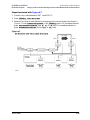
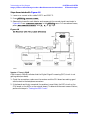
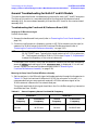
Testing between Two Analyzers
The ability of the analyzer's LAN to function can be easily tested by connecting two
analyzers together using a short length of cable with two RJ-45 connectors on each end.
However, a “crossover” cable must be used in order for this to work. Some network hubs
have the capability to make a crossover connection using two normal, or straight-through,
cables. If this is available, use it; otherwise a crossover cable can be made by following the
directions in the next section
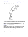
Constructing a Crossover Cable.
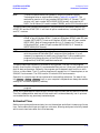
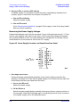
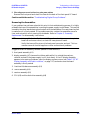
A crossover cable can be made from a normal LAN cable by connecting pin 1 from each
connector to pin 3 of the other connector. Likewise pin 2 should be connected to pin 6.
1. Strip away a few inches of the outside jacket insulation from the middle of a standard
LAN cable that has an RJ-45 connector on each end
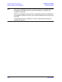
NOTE
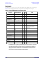
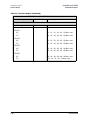
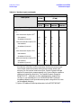
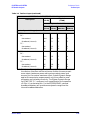
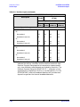
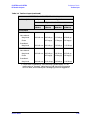
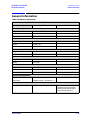
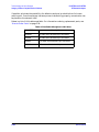
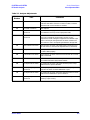
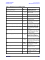
Most, but not all, LAN cables use the color coding listed in Table 4-4.
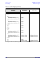
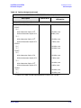
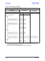
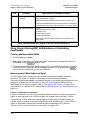
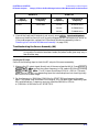
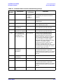
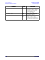
Table 4-4 List of Pin and Color Code Designations of a LAN cable
Pin Number
1 (transmit +)
2 (transmit −)
3 (receive +)
Color1
White/orange
Orange
White/green
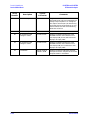
4
Blue
5
White/blue
6 (receive −)
Green
7
White/brown
8
Brown
1.
If your cable does not use this scheme, you will have
to determine each conductor with a continuity tester.
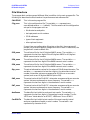
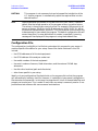
2. Cut the wires going to pins 1, 2, 3, and 6. Strip away a small amount of insulation from
each of the eight cut ends.
a. Connect the wire from pin 1 on one side of the cable to the wire from pin 3 on the
other side of the cable.
b. Connect the wire from pin 3 on one side of the cable to the wire from pin 1 on the
other side of the cable.
c. Connect the wire from pin 2 on one side of the cable to the wire from pin 6 on the
other side of the cable.
d. Connect the wire from pin 6 on one side of the cable to the wire from pin 2 on the
other side of the cable.
4-42
Service Guide