1
Section 2 Installation
DAX-1/DAX-3
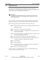
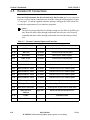
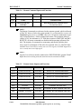
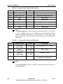
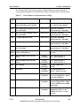
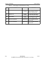
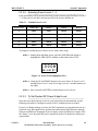
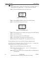
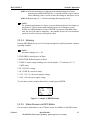
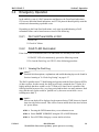
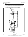
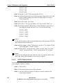
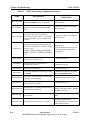
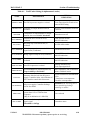
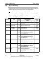
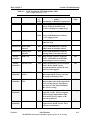
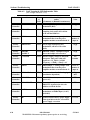
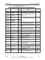
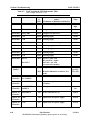
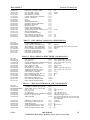
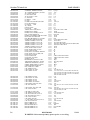
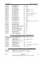
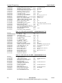
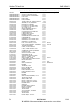
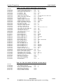
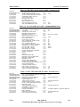
The following table lists pertinent jumpers and potentiometers, and provides their
corresponding designator value and function within each board in the DAXtransmitter.
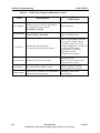
Table 2-7
DAX Jumpers and Potentiometers Listing
JP/R
(n)
NAME
Location
FUNCTION
JP1
Select either green or red Front
Panel LED during remote disable
External I/O
1-2 = Green @ remote disable
2-3 = Red @ remote disable
JP2
Ref. 10MHz input impedance select:
50 or 10k Ohms
External I/O
Short (in) = 50 Ohms
Open (removed) = 10k Ohms
JP3
RF Carrier input impedance select:
50 or 10k Ohms
External I/O
Short (in) = 50 Ohms
Open (removed) = 10k Ohms
JP4
(+) Input impedance select
External I/O
Short (in) = 600 Ohms
Open (removed) = 20k Ohms
JP5
(-) Input impedance select
External I/O
Short (in) = 600 Ohms
Open (removed) = 20k Ohms
JP6
IBOC Phase input impedance select:
50 or 10k Ohms
External I/O
Short (in) = 50 Ohms
Open (removed) = 10k Ohms
AC Low Trip Adjust
(early revision boards)
External I/O
AC Low Trip Adjust - Factory
use only
R118
(R107)
JP1
Back-up 10MHz clock reference
select
Exciter
Controller
1-2 = Clock reference 1
2-3 = Clock reference 2
JP2
Back-up 10MHz clock reference
select
Exciter
Controller
1-2 = Clock reference 1
2-3 = Clock reference 2
R25
RF SAMPLE
Exciter
Controller
Sets RF Sample level
(TP10)
R32
PDM ADJ
Exciter
Controller
Sets PDM Sample level
(TP13) - Factory use only
R37
IBOC MAG GAIN ADJUST
Exciter
Controller
Sets IBOC Mag level for A/D
converter input (TP22) - Adjust
for proper sidebands.
R39
AUDIO GAIN ADJUST
Exciter
Controller
Sets analog audio level for A/D
converter input (TP22) - Adjust
for 95% modulation at 10 dBm
audio input.
R43
+VS_DTG
Exciter
Controller
Dead Time Generator voltage
adjustment (TP29 - 1V per
100kHz of Carrier) - Factory
use only
5/2/13
888-2500-001
WARNING: Disconnect primary power prior to servicing.
2-29