1
Section 5 Maintenance and Alignments
5.3
DAX-1/DAX-3
Configuration
5.3.1
Change Remote Disable LED Color
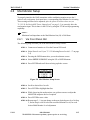
Depending on the installation requirements, the color of the Remote Disable LED can
be altered from the default.
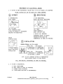
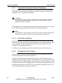
STEP 1
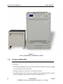
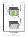
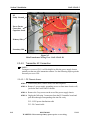
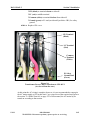
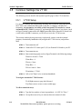
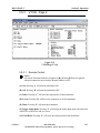
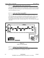
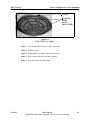
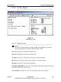
Locate the External I/O board by removing the front panel below the
control panel
STEP 2
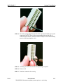
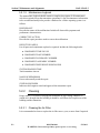
Locate JP1 and set accordingly
• Green at disabled remote: 1-2
• Red at disabled remote: 2-3
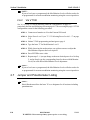
STEP 3
5.3.2
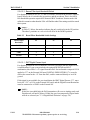
Replace front panel
Bessel Filter Input Bandwidth Select
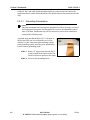
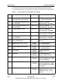
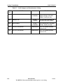
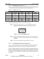
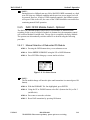
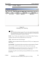
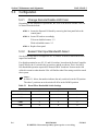
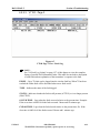
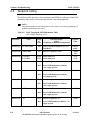
See the following table to configure the S2, S3, and S4 switches to match the desired
input filter bandwidth.
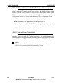
For digital operation be sure S2, S3, and S4 switches, located on the Exciter/Controller
board, all have the #1 switch in the up position, and the rest down. This is for full 50
kHz bandwidth operation required for domestic IBOC broadcast. Narrow-mode AM
utilized in countries other than the USA will find the other filter settings useful to match
their system.
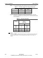
NOTE:
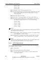
In Table 5-1 below, the number indicates the only switch to be in the UP position.
The other 3 positions on each switch will all be in the DOWN position.
Table 5-1
Bessel Filter Bandwidth Switch Settings
Desired Bandwidth
S2
S3
S4
50 kHz
1
1
1
10 kHz
2
2
2
9 kHz
3
3
3
5 kHz
4
4
4
5-4
888-2500-001
WARNING: Disconnect primary power prior to servicing.
5/2/2013