1
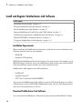
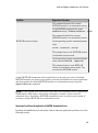
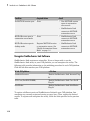
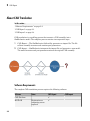
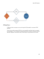
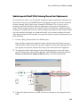
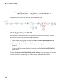
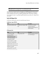
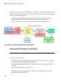
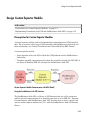
2
CAD Export
Guidelines for CAD Translation
In this section...
“How CAD Assemblies Are Translated into SimMechanics Models” on page 2-10
“Prepare CAD Assembly for Import into SimMechanics Model” on page 2-12
How CAD Assemblies Are Translated into SimMechanics Models
During CAD export, SimMechanics Link generates an XML file that maps CAD entities
onto equivalent SimMechanics entities. The following table indicates the correspondence
between the two types of entities.
CAD Entity
SimMechanics First Generation Equivalent
Part
Body
Constraints (Mates)
Joint
Reference coordinate system
Unconnected coordinate system ports
Assembly Reference
Fundamental Root: Root Ground — Weld – Root
Part
Subassembly
Subsystem
Subassembly Reference
Root Part
Fixed Part
Root Body – Weld – Body
Origins, References, Roots, and Root Bodies
Every CAD assembly has a single assembly origin and one or more assembly references
that do not move with respect to the origin. The positions and orientations of all parts
refer directly or indirectly to this origin.
A root body is a zero-mass, zero-inertia body used in the generated SimMechanics model
to represent one or more assembly references. A root body is always welded to ground,
so that its zero mass and zero inertia do not affect the model's dynamics. A root body is
necessary to represent a fixed anchor for part constraints in the original assembly. This
body can carry multiple coordinate systems for this purpose, while the single Ground
block in the generated model can carry only one.
Assembly Origin Mapped to SimMechanics World Origin
CAD translation maps the CAD assembly origin to the World coordinate system origin.
2-10