1
SIGNAL FLOW
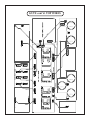
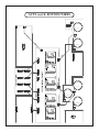
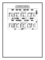
The signal-flow through the console is simple enough to describe and mostly follows the front panel
left-to-right layout. Three pairs of XLRs on the back panel are balanced line inputs associated with the
client‘s source format. These could typically be a superb DAC (or two) and an analog tape machine.
INPUT SELECTION
Next come a pair of XLRs that are direct outputs of the chosen input. Typically these outputs would
feed a pair of monitor control box inputs and are used for comparing the raw tracks that were brought
in versus the effect of the mastering process. Mastering engineers may use this as a “confidence check”
and as an immediate way to show the client the “before and after pictures”. There are other outputs
that can be used to check the final output after processors, and for a mid-point in the processor chain if
desired.
The chosen input then can be Left-Right swapped just for those occasional sessions when either the
mixing studio accidentally swapped cables or the mix seems to sound better in the opposite perspective.
The mix can also be polarity flipped. This reverses the “phase” (polarity is the correct term) of both the
left and right channels. Probably one wants the kick drum pushing the speaker out rather than sucking
the speaker inward. Most of the time, “Polarity Reverse” is a subtle effect and with some mixes the effect is inaudible. Strangely, the effect is often most pronounced on reed instruments and some types of
vocal character. It is usually worth a quick check to verify which way seems to sound best and/or seems
to have the kick pushing the woofer outward. If in doubt, leave the polarity alone.
The Input Selection, Left-Right Swap and Polarity Reverse are accomplished purely passively, and
are highly unlikely to damage the signals at all. This is achieved with simple sealed gold-contact relay closures. In fact, the Left channel and Right channel signal paths are generally on separate circuit
boards and/or widely separated physically to maintain ideal channel separation and cross-talk. Where a
signal meets a connector, two gold contact pins and two wires are used for extreme reliability. That feature is called “redundancy” so that if one expects one failure in one thousand without, one might expect
one failure in a million, given redundancy (1,000 X 1,000).
INPUT LEVEL SWITCHES
Next up are the two INPUT LEVEL rotary switches that provide 24 precise ½ dB gain steps. The
range is from 6 dB of boost to -5.5 dB of attenuation. Ultra-low distortion thin film 0.1% tolerance
resistors are combined with sealed gold contact Greyhill switches. As described earlier, the gain stage is
that new-topology fully balanced circuit followed by a pair of unity gain high current buffers.
There is a BYPASS switch that removes all active electronics for both the INPUT LEVEL and
OUTPUT LEVEL control circuits. This is one more form of confidence check that allows you to compare whether two sets of gain stages have any hint of possible signal degradation. It also allows one to
run the console in a 100% passive mode.