1
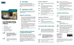
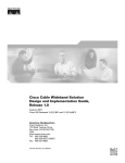
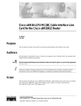
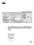
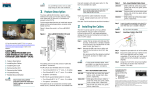
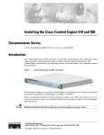
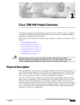
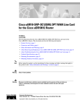
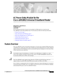
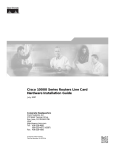
Cisco uBR10012 Universal Broadband Router
Fan Assembly Module
Document Part Number: OL-5093-01
October 2003
Product Numbers: UBR10-FAN-ASSY=, UBR10-FAN-CAB=
Revision History
Date
Revision
Reason
08/31/2001
78-11491-01
Original publication. This document is obsolete.
10/21/03
OL-5093-01
Moved document to online only, updated information and format.
Purpose
The purpose of this document is to provide installation, removal, and troubleshooting information for
the fan assembly module installed in the Cisco uBR10012 universal broadband router.
Audience
This document is intended for use by a field service engineer who is familiar with Cisco products and
headend cable installation procedures.
Warning
Only trained and qualified personnel should be allowed to install, replace, or service this equipment.
Statement 1030.
Corporate Headquarters:
Cisco Systems, Inc., 170 West Tasman Drive, San Jose, CA 95134-1706 USA
Copyright © 2003 Cisco Systems, Inc. All rights reserved.
Scope
This document includes procedures for installing and removing the fan assembly module that comes with
the Cisco uBR10012 universal broadband router. This document also includes technical specifications
and troubleshooting information.
Contents
•
Feature Overview, page 2
•
Part Numbers and Technical Specifications, page 4
•
Safety Warnings, page 5
•
Removing and Replacing the Fan Assembly Module, page 9
•
Replacing the Fan Assembly Cable, page 11
•
Troubleshooting the Fan Assembly, page 13
•
Related Documentation, page 14
•
Obtaining Documentation, page 14
•
Obtaining Technical Assistance, page 16
•
Obtaining Additional Publications and Information, page 17
Feature Overview
The Cisco uBR10012 universal broadband router uses a fan assembly module (Figure 1 on page 3)
containing four fans to supply cooling air to the chassis.
The fan assembly is located at the top of the chassis and is connected to the chassis with a blind mate
connector that plugs into a cable assembly and then into the chassis backplane.
Four internal fans draw cooling air into the front of the chassis and direct it across the internal
components to maintain an acceptable operating temperature. The air is exhausted through openings in
the rear of the chassis.
The fan assembly module works at variable speeds:
•
Low speed (with a clean air filter): approximately 280 cubic feet per minute (cmf)
•
High speed (with a clean air filter): approximately 450 cmf
The operating speed is determined by the fan assembly module. If the temperature at the fan’s outlet gets
to 40°C, then the blower starts to increase the speed of the fans. It does not reach high speed, however,
until the temperature at the outlet reaches 50°C.
Three LEDs (System OK, Single Fan Failure, and Multi-Fan Failure) located on the front of the fan
assembly indicate the status of the fans (see Table 1 on page 3).
Figure 1 on page 3 shows the fan assembly module.
Cisco uBR10012 Universal Broadband Router Fan Assembly Module
2
OL-5093-01
Figure 1
Fan Assembly Module
CISCO
10000
56413
Fan
assembly
CISCO
10000
AU
X
AU
X
A
C
E
TI
V
IT
TH
E
LI
N
K
R
Y
N
E
A
C
T
E
Table 1
TI
V
IT
TH
LI
E
N
K
R
Y
N
E
T
Fan Assembly LEDs and Their Function
LED
Status
Description
System OK
Green
System is functioning normally; all fans are operating.
Single Fan Failure
Yellow
A single fan has failed; system triggers alarms, but the fan assembly
is still able to properly cool the chassis. Repair or replace the fan
assembly immediately.
Multi-Fan Failure
Yellow
Two or more fans have failed, and if the operating temperature
inside the chassis rises too high, the system automatically shuts
down. Repair or replace the fan assembly immediately.
Cisco uBR10012 Universal Broadband Router Fan Assembly Module
OL-5093-01
3
Part Numbers and Technical Specifications
Table 2 lists the specifications for the Cisco uBR10012 universal broadband router fan assembly
module.
Table 2
Cisco uBR10012 Fan Assembly Module Specifications
Description
Specifications
Product number (fan assembly) UBR10-FAN-ASSY=
Product number (cable)
Dimensions
Weight
UBR10-FAN-CAB=
•
Height: 5.60 in. (14.22 cm)
•
Width: 19 in. (482.26 cm)
•
Depth: 16.15 in. (41.02 cm)
30 lb (13.61 kg)
AC-input voltage and frequency 110 to 240 VAC, 50 to 60 Hz
Power consumption
250 Watts (4 amps, not to exceed 6 amps at startup)
Airflow
Low speed (with clean air filter): 280 cfm1
High speed (with clean air filter): 450 cfm
MTBF
Temperature range
Relative humidity
Operating altitude
•
Fans, 248,509 hours
•
Fan Control, 596,65 hours
•
Operating: 41 to 104°F (5 to 40°C)
•
Storage: –40 to 158°F (–40 to 70°C)
•
Operating: 5 to 85%
•
Storage: 5 to 95%
–197 to 13,123 ft (–60 to 4000 m)
1. Cubic feet per minute
Cisco uBR10012 Universal Broadband Router Fan Assembly Module
4
OL-5093-01
Safety Warnings
Warning Definition
Warning
IMPORTANT SAFETY INSTRUCTIONS
This warning symbol means danger. You are in a situation that could cause bodily injury. Before you
work on any equipment, be aware of the hazards involved with electrical circuitry and be familiar
with standard practices for preventing accidents. Use the statement number provided at the end of
each warning to locate its translation in the translated safety warnings that accompanied this
device. Statement 1071
SAVE THESE INSTRUCTIONS
Waarschuwing
BELANGRIJKE VEILIGHEIDSINSTRUCTIES
Dit waarschuwingssymbool betekent gevaar. U verkeert in een situatie die lichamelijk letsel kan
veroorzaken. Voordat u aan enige apparatuur gaat werken, dient u zich bewust te zijn van de bij
elektrische schakelingen betrokken risico's en dient u op de hoogte te zijn van de standaard
praktijken om ongelukken te voorkomen. Gebruik het nummer van de verklaring onderaan de
waarschuwing als u een vertaling van de waarschuwing die bij het apparaat wordt geleverd, wilt
raadplegen.
BEWAAR DEZE INSTRUCTIES
Varoitus
TÄRKEITÄ TURVALLISUUSOHJEITA
Tämä varoitusmerkki merkitsee vaaraa. Tilanne voi aiheuttaa ruumiillisia vammoja. Ennen kuin
käsittelet laitteistoa, huomioi sähköpiirien käsittelemiseen liittyvät riskit ja tutustu
onnettomuuksien yleisiin ehkäisytapoihin. Turvallisuusvaroitusten käännökset löytyvät laitteen
mukana toimitettujen käännettyjen turvallisuusvaroitusten joukosta varoitusten lopussa näkyvien
lausuntonumeroiden avulla.
SÄILYTÄ NÄMÄ OHJEET
Attention
IMPORTANTES INFORMATIONS DE SÉCURITÉ
Ce symbole d'avertissement indique un danger. Vous vous trouvez dans une situation pouvant
entraîner des blessures ou des dommages corporels. Avant de travailler sur un équipement, soyez
conscient des dangers liés aux circuits électriques et familiarisez-vous avec les procédures
couramment utilisées pour éviter les accidents. Pour prendre connaissance des traductions des
avertissements figurant dans les consignes de sécurité traduites qui accompagnent cet appareil,
référez-vous au numéro de l'instruction situé à la fin de chaque avertissement.
CONSERVEZ CES INFORMATIONS
Cisco uBR10012 Universal Broadband Router Fan Assembly Module
OL-5093-01
5
Warnung
WICHTIGE SICHERHEITSHINWEISE
Dieses Warnsymbol bedeutet Gefahr. Sie befinden sich in einer Situation, die zu Verletzungen führen
kann. Machen Sie sich vor der Arbeit mit Geräten mit den Gefahren elektrischer Schaltungen und
den üblichen Verfahren zur Vorbeugung vor Unfällen vertraut. Suchen Sie mit der am Ende jeder
Warnung angegebenen Anweisungsnummer nach der jeweiligen Übersetzung in den übersetzten
Sicherheitshinweisen, die zusammen mit diesem Gerät ausgeliefert wurden.
BEWAHREN SIE DIESE HINWEISE GUT AUF.
Avvertenza
IMPORTANTI ISTRUZIONI SULLA SICUREZZA
Questo simbolo di avvertenza indica un pericolo. La situazione potrebbe causare infortuni alle
persone. Prima di intervenire su qualsiasi apparecchiatura, occorre essere al corrente dei pericoli
relativi ai circuiti elettrici e conoscere le procedure standard per la prevenzione di incidenti.
Utilizzare il numero di istruzione presente alla fine di ciascuna avvertenza per individuare le
traduzioni delle avvertenze riportate in questo documento.
CONSERVARE QUESTE ISTRUZIONI
Advarsel
VIKTIGE SIKKERHETSINSTRUKSJONER
Dette advarselssymbolet betyr fare. Du er i en situasjon som kan føre til skade på person. Før du
begynner å arbeide med noe av utstyret, må du være oppmerksom på farene forbundet med
elektriske kretser, og kjenne til standardprosedyrer for å forhindre ulykker. Bruk nummeret i slutten
av hver advarsel for å finne oversettelsen i de oversatte sikkerhetsadvarslene som fulgte med denne
enheten.
TA VARE PÅ DISSE INSTRUKSJONENE
Aviso
INSTRUÇÕES IMPORTANTES DE SEGURANÇA
Este símbolo de aviso significa perigo. Você está em uma situação que poderá ser causadora de
lesões corporais. Antes de iniciar a utilização de qualquer equipamento, tenha conhecimento dos
perigos envolvidos no manuseio de circuitos elétricos e familiarize-se com as práticas habituais de
prevenção de acidentes. Utilize o número da instrução fornecido ao final de cada aviso para
localizar sua tradução nos avisos de segurança traduzidos que acompanham este dispositivo.
GUARDE ESTAS INSTRUÇÕES
¡Advertencia!
INSTRUCCIONES IMPORTANTES DE SEGURIDAD
Este símbolo de aviso indica peligro. Existe riesgo para su integridad física. Antes de manipular
cualquier equipo, considere los riesgos de la corriente eléctrica y familiarícese con los
procedimientos estándar de prevención de accidentes. Al final de cada advertencia encontrará el
número que le ayudará a encontrar el texto traducido en el apartado de traducciones que acompaña
a este dispositivo.
GUARDE ESTAS INSTRUCCIONES
Cisco uBR10012 Universal Broadband Router Fan Assembly Module
6
OL-5093-01
Varning!
VIKTIGA SÄKERHETSANVISNINGAR
Denna varningssignal signalerar fara. Du befinner dig i en situation som kan leda till personskada.
Innan du utför arbete på någon utrustning måste du vara medveten om farorna med elkretsar och
känna till vanliga förfaranden för att förebygga olyckor. Använd det nummer som finns i slutet av
varje varning för att hitta dess översättning i de översatta säkerhetsvarningar som medföljer denna
anordning.
SPARA DESSA ANVISNINGAR
Cisco uBR10012 Universal Broadband Router Fan Assembly Module
OL-5093-01
7
Electrical Equipment Guidelines
Follow these basic guidelines when working with any electrical equipment:
•
Before beginning any procedures requiring access to the chassis interior, locate the emergency
power-off switch for the room in which you are working.
•
Disconnect all power and external cables before moving a chassis.
•
Do not work alone when potentially hazardous conditions exist.
•
Never assume that power has been disconnected from a circuit; always check.
•
Do not perform any action that creates a potential hazard to people or makes the equipment unsafe.
•
Carefully examine your work area for possible hazards such as moist floors, ungrounded power
extension cables, and missing safety grounds.
Preventing Electrostatic Discharge Damage
Electrostatic discharge (ESD) damage, which occurs when electronic cards or components are
improperly handled, can result in complete or intermittent failures. The AC-input power shelf and its AC
power modules contain a printed circuit card that is fixed in a metal carrier. Electromagnetic interference
(EMI) shielding and connectors are integral components of the carrier. Although the metal carrier helps
to protect the cards from ESD, use an anti-static strap each time you handle the modules.
Following are guidelines for preventing ESD damage:
Caution
•
Always use an ESD-preventive wrist or ankle strap and ensure that it makes good skin contact.
Before removing a card from the chassis, connect the equipment end of the strap to a bare metal,
unpainted surface on the chassis or rack-mount.
•
Handle components by the carrier edges only; avoid touching the card components or any connector
pins.
•
When removing a module, place it on an anti-static surface or in a static-shielding bag. If the module
will be returned to the factory, immediately place it in a static-shielding bag.
•
Avoid contact between the modules and clothing. The wrist strap protects the card from ESD
voltages on the body only; ESD voltages on clothing can still cause damage.
For safety, periodically check the resistance value of the anti-static strap. The measurement should
be between 1 and 10 megohms.
Cisco uBR10012 Universal Broadband Router Fan Assembly Module
8
OL-5093-01
Removing and Replacing the Fan Assembly Module
The fan assembly module does not need to be replaced when it is operating normally. If a failure LED
comes on, use the following procedure to remove and reinsert the fan assembly module to test the
connection. If the failure LED is still on after removing and reinserting the module, use the following
procedure to replace the fan assembly module.
•
Single Fan Failure—This yellow LED indicates that one of the four fans in the module has failed.
The module can still provide enough cooling to safely operate the Cisco uBR10012 universal
broadband router chassis, but it might begin operating the fans in its high-speed mode to do so. If
this LED comes on, replace the fan assembly module as soon as is conveniently possible.
•
Multiple Fan Failure—This yellow LED indicates that two or more fans in the module have failed,
and that the module is no longer able to consistently cool the Cisco uBR10012 universal broadband
router chassis. To prevent overheating the chassis and possible damage to the line cards and other
modules, replace the fan assembly module immediately.
The fan assembly module supports hot-swapping and can be replaced without interrupting system
operation.
Caution
Do not run the Cisco uBR10012 universal broadband router chassis without a working fan assembly
module for more than three minutes. To prevent the possibility of the system overheating, be sure that
the replacement fan assembly module is out of its box and packaging, so it is ready to install as soon
as the defective module is removed.
Unpack the Fan Assembly Module
To unpack the fan assembly module, complete the following steps:
Step 1
Open the shipping carton by cutting the packing tape along the flaps on the top of the box.
Step 2
Lift off the top layer of packaging to expose the module.
Step 3
Remove the fan assembly module from the box.
Step 4
Keep the packaging and the carton to return the defective unit to the factory. See the “Obtaining
Technical Assistance” section on page 16 for more information.
Cisco uBR10012 Universal Broadband Router Fan Assembly Module
OL-5093-01
9
Remove the Fan Assembly Module
Step 1
Remove the front cover by lifting it up slightly and then pulling it toward you (see Figure 2).
Step 2
Loosen the captive screws on each side of the fan assembly module.
Step 3
Pull the module out of the chassis (see Figure 3 on page 11).
Step 4
If you are replacing the cable and the fan assembly module, or if you are replacing just the cable, see the
“Replace the Fan Assembly Cable” section on page 12.
Figure 2
Removing the Front Cover
C
AU
N
S
O
C
LE
O
AU
TIV
TH
N
E
K
IT
R
S
O
E
LE
POWER
MISWIR
E
FAULT
POWER
MISWIRE
FAULT
X
A
C
Y
N
E
T
TIV
TH
LI
1
OT
0
OT
SL
SL
1
OT
0
OT
SL
SL
LI
N
X
A
C
E
POWER
MISWIR
E
FAULT
CISCO
10000
O
IPSU SA TUS
POWER
MISWIRE
FAULT
IPSUM SANCT
IPSUM
CISCO
10000
N
E
K
IT
R
Y
N
E
T
ALARMS
A
C
ALARMS
O
C
R
A
C
O
IT
M
A
IC
A
R
IC
A
S
L
JO
R
M
IN
O
R
56422
TA
TU
FA S
IL
PERFORMANCE ROUTING ENGINE
TA
TU
FA S
IL
IT
M
A
PERFORMANCE ROUTING ENGINE
S
C
R
L
JO
R
M
IN
O
Cisco uBR10012 Universal Broadband Router Fan Assembly Module
10
OL-5093-01
Locations of Screws
CISCO
10000
CISCO
56293
Figure 3
Install the Fan Assembly Module
Step 1
Using two hands, align the new fan assembly module in the slot in the chassis, and push it back firmly.
Make sure that the connectors on the can assembly securely connect to the backplane.
Step 2
Verify that the FANS OK LED is on (green). If the FANS OK LED is not on or if the FAN FAILURE
LED comes on (yellow), try reseating the fan assembly module.
Step 3
Tighten the captive screws on each side of the fan assembly module.
Step 4
Replace the front cover.
a.
Slide the cover onto the four corner posts of the chassis.
b.
Push down so that the posts are seated in the grooves above the cover holes.
Replacing the Fan Assembly Cable
The fan assembly cable connects the fan assembly to the backplane. The cable is located inside the
chassis, underneath the fan assembly. Ordinarily the cable is not removed when a fan assembly module
is removed from the chassis.
Replacing a fan cable requires removing the cooling facilities of the chassis. It is not necessary to remove
power from the chassis for this procedure. However, because you are shutting down the fans that cool
the chassis and boards, it is important to have the new cable ready for immediate installation.
Cisco uBR10012 Universal Broadband Router Fan Assembly Module
OL-5093-01
11
Remove the Cable
To replace the fan assembly cable, perform the following steps:
Step 1
Remove the front cover.
Step 2
Remove the fan assembly. See the “Remove the Fan Assembly Module” section on page 10.
Step 3
See Figure 4. Note that the cable has two “U” shaped bends that allow the cable to curve back into the
brackets and fit snugly on the bottom of the fan module enclosure.
Figure 4
CISCO
10000
Location of Fan Cable Inside the Chassis
62337
CISCO
10000
AU
X
AU
X
A
C
TIV
IT
E
TH Y
E
LIN RN
E
T
K
A
C
TIV
IT
Y
E
TH
E
LIN RN
K ET
Step 4
Reach into the chassis and disconnect the cable from the rear bracket. Push the tabs on the bracket open.
Step 5
Disconnect the cable from the front connector and remove the cable from the chassis.
Replace the Fan Assembly Cable
Note
The cable has different connectors on each end.
Fan Cable
62338
Figure 5
Male connector
Female connector
Cisco uBR10012 Universal Broadband Router Fan Assembly Module
12
OL-5093-01
Step 1
Verify which connector goes in the bracket in the back of the chassis and which connector goes into the
front connector.
Step 2
Bend the cable in a “U” shape at both ends, to facilitate getting the cable into the rear bracket. See
Figure 4 on page 12.
Tip
Use the existing cable as a template.
Step 3
Install the cable in the rear bracket.
Step 4
Make sure that the cable lays flat on the enclosure bottom so as not to restrict the movement of the cable
assembly as it is pushed back into the chassis.
Step 5
Connect the cable with the front connector.
Step 6
Slide the fan assembly module back into the chassis. The module should slide smoothly back into the
chassis without interference with the cable.
Tip
If the fan assembly module does not slide easily into the chassis, remove the module and check
the location of the cable. The cable should lay flat along the bottom of the fan assembly
enclosure.
Troubleshooting the Fan Assembly
Check the following to help isolate a problem with the cooling system:
•
When you start up the system, do the fans start operating?
When the fans are operating, you should be able to hear them. You should also be able to feel air
being drawn in at the bottom front and expelled at the top rear of the chassis.
– If no, there is a problem with the fan or power. See the Cisco uBR10012 Series Hardware
Installation Guide, Troubleshooting the Power Subsystem, at the following URL:
http://www.cisco.com/univercd/cc/td/doc/product/cable/ubr10k/ubr10012/hig/u10ktrb.htm
– If yes, continue with the next step.
•
Is the System OK LED on the fan assembly module on (green) and are the other two LEDs (Single
Fan Failure and Multiple Fan Failure) off?
– If yes, the system is operating normally.
– If no, remove the fan assembly module and reinsert it. If this does not help, examine the LED
that is on. The Single Fan Failure LED indicates that one fan of the four has failed, but that the
system is still able to adequately cool the chassis; repair or replace the fan assembly module as
soon as possible. The Multiple Fan Failure LED indicates that more than one fan has failed, and
that the fan assembly module is no longer able to adequately cool the Cisco uBR10012 series
chassis. Replace the fan assembly module as soon as possible.
Cisco uBR10012 Universal Broadband Router Fan Assembly Module
OL-5093-01
13
•
The following messages, if displayed, indicate that the system has detected a critical
overtemperature condition or out-of-tolerance power inside the chassis:
Queued messages:
00:01:19:%ENVM-4-ENVWARN:+2.5 V measured at +2.59
00:01:19:%ENVM-4-ENVWARN:+5.15 V measured at +5.31
00:00:19:%ENVM-2-ENVCRIT:chassis
00:00:19:%ENVM-2-ENVCRIT:chassis
00:00:19:%ENVM-2-ENVCRIT:chassis
00:00:19:%ENVM-2-ENVCRIT:chassis
core measured at 31C/87F
inlet measured at 27C/80F
outlet 1 measured at 30C/86F
outlet 2 measured at 30C/86F
Although an overtemperature condition is unlikely at initial startup, ensure that heated exhaust air from
other equipment is not entering the router’s inlet vent and that there is sufficient clearance around the
sides of the chassis to allow cooling air to flow.
Note
The above message could also indicate a faulty component or temperature sensor. Use the show
environment or show environment table command to display the internal chassis environment.
If you experience trouble with the startup that is not resolved with these procedures, manually power off
the router and contact a service representative for assistance and further instructions.
Perform the following if the FAN FAILURE LED is on:
•
Reseat the fan assembly module.
•
Remove the rear safety cover and be sure that the fan assembly module cable is connected securely.
Related Documentation
Cisco uBR10012 Universal Broadband Router Hardware Installation Guide at the following URL:
http://www.cisco.com/univercd/cc/td/doc/product/cable/ubr10k/ubr10012/hig/index.htm
Cisco uBR10012 Universal Broadband Router Software Configuration Guide at the following URL:
http://www.cisco.com/univercd/cc/td/doc/product/cable/ubr10k/ubr10012/scg/index.htm
Cisco CMTS Feature Guide at the following URL:
http://www.cisco.com/univercd/cc/td/doc/product/cable/cab_rout/cmtsfg/index.htm
Obtaining Documentation
Cisco provides several ways to obtain documentation, technical assistance, and other technical
resources. These sections explain how to obtain technical information from Cisco Systems.
Cisco.com
You can access the most current Cisco documentation on the World Wide Web at this URL:
http://www.cisco.com/univercd/home/home.htm
Cisco uBR10012 Universal Broadband Router Fan Assembly Module
14
OL-5093-01
You can access the Cisco website at this URL:
http://www.cisco.com
International Cisco websites can be accessed from this URL:
http://www.cisco.com/public/countries_languages.shtml
Documentation CD-ROM
Cisco documentation and additional literature are available in a Cisco Documentation CD-ROM
package, which may have shipped with your product. The Documentation CD-ROM is updated regularly
and may be more current than printed documentation. The CD-ROM package is available as a single unit
or through an annual or quarterly subscription.
Registered Cisco.com users can order a single Documentation CD-ROM (product number
DOC-CONDOCCD=) through the Cisco Ordering tool:
http://www.cisco.com/en/US/partner/ordering/ordering_place_order_ordering_tool_launch.html
All users can order annual or quarterly subscriptions through the online Subscription Store:
http://www.cisco.com/go/subscription
Click Subscriptions & Promotional Materials in the left navigation bar.
Ordering Documentation
You can find instructions for ordering documentation at this URL:
http://www.cisco.com/univercd/cc/td/doc/es_inpck/pdi.htm
You can order Cisco documentation in these ways:
•
Registered Cisco.com users (Cisco direct customers) can order Cisco product documentation from
the Networking Products MarketPlace:
http://www.cisco.com/en/US/partner/ordering/index.shtml
•
Nonregistered Cisco.com users can order documentation through a local account representative by
calling Cisco Systems Corporate Headquarters (California, USA) at 408 526-7208 or, elsewhere in
North America, by calling 800 553-NETS (6387).
Documentation Feedback
You can submit e-mail comments about technical documentation to [email protected].
You can submit comments by using the response card (if present) behind the front cover of your
document or by writing to the following address:
Cisco Systems
Attn: Customer Document Ordering
170 West Tasman Drive
San Jose, CA 95134-9883
We appreciate your comments.
Cisco uBR10012 Universal Broadband Router Fan Assembly Module
OL-5093-01
15
Obtaining Technical Assistance
For all customers, partners, resellers, and distributors who hold valid Cisco service contracts, the Cisco
Technical Assistance Center (TAC) provides 24-hour-a-day, award-winning technical support services,
online and over the phone. Cisco.com features the Cisco TAC website as an online starting point for
technical assistance. If you do not hold a valid Cisco service contract, please contact your reseller.
Cisco TAC Website
The Cisco TAC website (http://www.cisco.com/tac) provides online documents and tools for
troubleshooting and resolving technical issues with Cisco products and technologies. The Cisco TAC
website is available 24 hours a day, 365 days a year.
Accessing all the tools on the Cisco TAC website requires a Cisco.com user ID and password. If you
have a valid service contract but do not have a login ID or password, register at this URL:
http://tools.cisco.com/RPF/register/register.do
Opening a TAC Case
Using the online TAC Case Open Tool (http://www.cisco.com/tac/caseopen) is the fastest way to open
P3 and P4 cases. (P3 and P4 cases are those in which your network is minimally impaired or for which
you require product information.) After you describe your situation, the TAC Case Open Tool
automatically recommends resources for an immediate solution. If your issue is not resolved using the
recommended resources, your case will be assigned to a Cisco TAC engineer.
For P1 or P2 cases (P1 and P2 cases are those in which your production network is down or severely
degraded) or if you do not have Internet access, contact Cisco TAC by telephone. Cisco TAC engineers
are assigned immediately to P1 and P2 cases to help keep your business operations running smoothly.
To open a case by telephone, use one of the following numbers:
Asia-Pacific: +61 2 8446 7411 (Australia: 1 800 805 227)
EMEA: +32 2 704 55 55
USA: 1 800 553-2447
For a complete listing of Cisco TAC contacts, go to this URL:
http://www.cisco.com/warp/public/687/Directory/DirTAC.shtml
TAC Case Priority Definitions
To ensure that all cases are reported in a standard format, Cisco has established case priority definitions.
Priority 1 (P1)—Your network is “down” or there is a critical impact to your business operations. You
and Cisco will commit all necessary resources around the clock to resolve the situation.
Priority 2 (P2)—Operation of an existing network is severely degraded, or significant aspects of your
business operation are negatively affected by inadequate performance of Cisco products. You and Cisco
will commit full-time resources during normal business hours to resolve the situation.
Priority 3 (P3)—Operational performance of your network is impaired, but most business operations
remain functional. You and Cisco will commit resources during normal business hours to restore service
to satisfactory levels.
Cisco uBR10012 Universal Broadband Router Fan Assembly Module
16
OL-5093-01
Priority 4 (P4)—You require information or assistance with Cisco product capabilities, installation, or
configuration. There is little or no effect on your business operations.
Obtaining Additional Publications and Information
Information about Cisco products, technologies, and network solutions is available from various online
and printed sources.
•
The Cisco Product Catalog describes the networking products offered by Cisco Systems, as well as
ordering and customer support services. Access the Cisco Product Catalog at this URL:
http://www.cisco.com/en/US/products/products_catalog_links_launch.html
•
Cisco Press publishes a wide range of general networking, training and certification titles. Both new
and experienced user will benefit from these publications. For current Cisco Press titles and other
information, go to Cisco Press online at this URL:
http://www.ciscopress.com
•
Packet magazine is the Cisco quarterly publication that provides the latest networking trends,
technology breakthroughs, and Cisco products and solutions to help industry professionals get the
most from their networking investment. Included are networking deployment and troubleshooting
tips, configuration examples, customer case studies, tutorials and training, certification information,
and links to numerous in-depth online resources. You can access Packet magazine at this URL:
http://www.cisco.com/packet
•
iQ Magazine is the Cisco bimonthly publication that delivers the latest information about Internet
business strategies for executives. You can access iQ Magazine at this URL:
http://www.cisco.com/go/iqmagazine
•
Internet Protocol Journal is a quarterly journal published by Cisco Systems for engineering
professionals involved in designing, developing, and operating public and private internets and
intranets. You can access the Internet Protocol Journal at this URL:
http://www.cisco.com/en/US/about/ac123/ac147/about_cisco_the_internet_protocol_journal.html
•
Training—Cisco offers world-class networking training. Current offerings in network training are
listed at this URL:
http://www.cisco.com/en/US/learning/index.html
Cisco uBR10012 Universal Broadband Router Fan Assembly Module
OL-5093-01
17
This document is to be used in conjunction with the documents listed in the “Related Documentation” section.
CCVP, the Cisco logo, and Welcome to the Human Network are trademarks of Cisco Systems, Inc.; Changing the Way We Work, Live, Play, and Learn is
a service mark of Cisco Systems, Inc.; and Access Registrar, Aironet, Catalyst, CCDA, CCDP, CCIE, CCIP, CCNA, CCNP, CCSP, Cisco, the Cisco
Certified Internetwork Expert logo, Cisco IOS, Cisco Press, Cisco Systems, Cisco Systems Capital, the Cisco Systems logo, Cisco Unity,
Enterprise/Solver, EtherChannel, EtherFast, EtherSwitch, Fast Step, Follow Me Browsing, FormShare, GigaDrive, HomeLink, Internet Quotient, IOS,
iPhone, IP/TV, iQ Expertise, the iQ logo, iQ Net Readiness Scorecard, iQuick Study, LightStream, Linksys, MeetingPlace, MGX, Networkers,
Networking Academy, Network Registrar, PIX, ProConnect, ScriptShare, SMARTnet, StackWise, The Fastest Way to Increase Your Internet Quotient,
and TransPath are registered trademarks of Cisco Systems, Inc. and/or its affiliates in the United States and certain other countries.
All other trademarks mentioned in this document or Website are the property of their respective owners. The use of the word partner does not imply a
partnership relationship between Cisco and any other company. (0711R)
Copyright © 2003 Cisco Systems, Inc. All rights reserved.
Printed in the USA on recycled paper containing 10% postconsumer waste.
Cisco uBR10012 Universal Broadband Router Fan Assembly Module
18
OL-5093-01