1
Version 8.0
Part No. 308679-A Rev. 00
December 1999
4401 Great America Parkway
Santa Clara, CA 95054
Nortel Networks
5399 Access Switch Hardware
Installation Guide
Copyright © 1999 Nortel Networks
All rights reserved. Printed in the USA. December 1999.
The information in this document is subject to change without notice. The statements, configurations, technical data,
and recommendations in this document are believed to be accurate and reliable, but are presented without express or
implied warranty. Users must take full responsibility for their applications of any products specified in this document.
The information in this document is proprietary to Nortel Networks NA Inc.
Trademarks
NORTEL NETWORKS is a trademark of Nortel Networks.
Annex, Remote Annex, Annex Manager, Remote Annex 2000, Remote Annex 4000, Remote Annex 6100, Remote
Annex 6300, Remote Annex 5390/Async, Remote Annex 5391/CT1, Remote Annex 5393/PRI, BayStack Remote
Annex 2000 Server, Quick2Config, Bay Networks, Bay Networks Press, and the Bay Networks logo are trademarks
of Nortel Networks, Inc.
Microsoft, MS, MS-DOS, Win32, Windows, and Windows NT are registered trademarks of Microsoft Corporation.
All other trademarks and registered trademarks are the property of their respective owners.
Statement of Conditions
In the interest of improving internal design, operational function, and/or reliability, Nortel Networks NA Inc. reserves
the right to make changes to the products described in this document without notice.
Nortel Networks NA Inc. does not assume any liability that may occur due to the use or application of the product(s)
or circuit layout(s) described herein.
USA Requirements Only
Federal Communications Commission (FCC) Compliance Notice: Radio Frequency Notice
Note: This equipment has been tested and found to comply with the limits for a Class A digital device, pursuant to
Part 15 of the FCC rules. These limits are designed to provide reasonable protection against harmful interference
when the equipment is operated in a commercial environment. This equipment generates, uses, and can radiate radio
frequency energy. If it is not installed and used in accordance with the instruction manual, it may cause harmful
interference to radio communications. Operation of this equipment in a residential area is likely to cause harmful
interference, in which case users will be required to take whatever measures may be necessary to correct the
interference at their own expense.
European Requirements Only
EN 55 022 Statement
This is to certify that the Nortel Networks <product or system name> is shielded against the generation of radio
interference in accordance with the application of Council Directive 89/336/EEC, Article 4a. Conformity is declared
by the application of EN 55 022 Class A (CISPR 22).
Warning: This is a Class A product. In a domestic environment, this product may cause radio interference, in which
case, the user may be required to take appropriate measures.
Achtung: Dieses ist ein Gerät der Funkstörgrenzwertklasse A. In Wohnbereichen können bei Betrieb dieses Gerätes
Rundfunkstörungen auftreten, in welchen Fällen der Benutzer für entsprechende Gegenmaßnahmen verantwortlich
ist.
Attention: Ceci est un produit de Classe A. Dans un environnement domestique, ce produit risque de créer des
interférences radioélectriques, il appartiendra alors à l’utilisateur de prendre les mesures spécifiques appropriées.
ii
308679-A Rev. 00
EC Declaration of Conformity
This product conforms (or these products conform) to the provisions of Council Directive 89/336/EEC and
73/23/EEC. The Declaration of Conformity is available on the Nortel Networks World Wide Web site at
http://libra2.corpwest.baynetworks.com/cgi-bin/ndCGI.exe/DocView/.
Japan/Nippon Requirements Only
Voluntary Control Council for Interference (VCCI) Statement
Taiwan Requirements
ABureau of Standards, Metrology and Inspection (BSMI) Statement
308679-A Rev. 00
iii
Canada Requirements Only
Canadian Department of Communications Radio Interference Regulations
This digital apparatus (<product or system name>) does not exceed the Class A limits for radio-noise emissions from
digital apparatus as set out in the Radio Interference Regulations of the Canadian Department of Communications.
Règlement sur le brouillage radioélectrique du ministère des Communications
Cet appareil numérique (<product or system name>) respecte les limites de bruits radioélectriques visant les appareils
numériques de classe A prescrites dans le Règlement sur le brouillage radioélectrique du ministère des
Communications du Canada.
Canada CS-03 Rules and Regulations
Notice: The Industry Canada label identifies certified equipment. This certification means that the equipment meets
telecommunications network protective, operational and safety requirements as prescribed in the appropriate Terminal
Equipment Technical Requirements document(s). The Department does not guarantee the equipment will operate to
the user’s satisfaction.
Before installing this equipment, users should ensure that it is permissible to be connected to the facilities of the local
telecommunications company. The equipment must also be installed using an acceptable method of connection. The
customer should be aware that compliance with the above conditions may not prevent the degradation of service in
some situations.
Repairs to certified equipment should be coordinated by a representative designated by the supplier. Any repairs or
alterations made by the user to this equipment, or equipment malfunctions, may give the telecommunications
company cause to request the user to disconnect the equipment.
Users should ensure for their own protection that the electrical ground connections of the power utility, telephone lines
and internal metallic water pipe system, if present, are connected together. This precaution may be particularly
important in rural areas.
Caution: Users should not attempt to make such connections themselves, but should contact the appropriate electric
inspection authority, or electrician, as appropriate.
Notice: For equipment using loopstart lines, please note that the Ringer Equivalence Number (REN) assigned to each
terminal device provides an indication of the maximum number of terminals allowed to be connected to a telephone
interface. The termination on an interface may consist of any combination of devices subject only to the requirement
that the sum of the Ringer Equivalence Numbers of all the devices does not exceed 5. The REN is located on the “FCC
Rules Part 68” label located on the bracket of the module, or on the back of the unit.
Canada CS-03 -- Règles et règlements
Avis: L'étiquette d'Industrie Canada identifie le matériel homologué. Cette étiquette certifie que le matériel est
conforme aux normes de protection, d'exploitation et de sécurité des réseaux de télécommunications, comme le
prescrivent les documents concernant les exigences techniques relatives au matériel terminal. Le Ministère n'assure
toutefois pas que le matériel fonctionnera à la satisfaction de l'utilisateur.
Avant d'installer ce matériel, l'utilisateur doit s'assurer qu'il est permis de le raccorder aux installations de l'entreprise
locale de télécommunication. Le matériel doit également être installé en suivant une méthode acceptée de
raccordement. L'abonné ne doit pas oublier qu'il est possible que la conformité aux conditions énoncées ci-dessus
n'empêche pas la dégradation du service dans certaines situations.
Les réparations de matériel homologué doivent être coordonnées par un représentant désigné par le fournisseur.
L'entreprise de télécommunications peut demander à l'utilisateur de débrancher un appareil à la suite de réparations ou
de modifications effectuées par l'utilisateur ou à cause de mauvais fonctionnement.
Pour sa propre protection, l'utilisateur doit s'assurer que tous les fils de mise à la terre de la source d'énergie électrique,
des lignes téléphoniques et des canalisations d'eau métalliques, s'il y en a, sont raccordés ensemble. Cette précaution
est particulièrement importante dans les régions rurales.
iv
308679-A Rev. 00
Avertissement: L'utilisateur ne doit pas tenter de faire ces raccordements lui-même; il doit avoir recours à un service
d'inspection des installations électriques, ou à un électricien, selon le cas.
Avis: Veuillez prendre note que pour tout appareillage supportant des lignes de type “loopstart,” l'indice d'équivalence
de la sonnerie (IES) assigné à chaque dispositif terminal indique le nombre maximal de terminaux qui peuvent être
raccordés à une interface. La terminaison d'une interface téléphonique peut consister en une combinaison de quelques
dispositifs, à la seule condition que la somme d'indices d'équivalence de la sonnerie de tous les dispositifs n'excède pas
5. Le REN figure sur l’étiquette “FCC Rules Part 68” située sur le support du module ou à l’arrière de l’unité.
FCC Part 68 Compliance Statement
This equipment complies with Part 68 of FCC Rules. All direct connections to telephone network lines must be made
using standard plugs and jacks compliant with FCC Part 68. Please note the following:
1.
You are required to request service from the telephone company before you connect the unit to a network. When
you request service, you must provide the telephone company with the following data:
•
When you request T1 Service, you must provide the telephone company with
--
The Facility Interface Code
Provide the telephone company with all the codes below:
-
04DU9-BN (1.544 MB, D4 framing format)
04DU9-DN (1.544 MB, D4 framing format with B8ZF coding)
04DU9-1KN (1.544 MB, ESF framing format)
04DU9-1SN (1.544 MB, ESF framing format with B8ZF coding)
04DU9-1ZN (1.544 MB, ANSI ESF and ZBTSI without line power)
The telephone company will select the code it has available.
•
•
--
The Service Order Code(s) (SOC): 6.0Y
--
The required Universal Service Order Code (USOC) jack: RJ48C
When you request ISDN “U” Interface Service, you must provide the telephone company with
--
The Facility Interface Code: 02IS5
--
The Service Order Code(s) (SOC): 6.0F
--
The required Universal Service Order Code (USOC) jack: RJ49C
When you request ISDN “S/T” Interface Service, you must provide the telephone company with
--
The Service Order Code(s) (SOC): 6.0P
--
The make, model number, and FCC Registration number of the NT1
Note: ISDN S/T cannot be directly connected to the network.
•
When you request Primary Rate ISDN Service, you must provide the telephone company with
--
The Facility Interface Code: 04DU9-1SN (1.544 MB, ESF framing format with B8ZF coding)
--
The Service Order Code(s) (SOC): 6.0Y
--
The required Universal Service Order Code (USOC) jack: RJ48C
2.
Your telephone company may make changes to its facilities, equipment, operations, or procedures that could
affect the proper functioning of your equipment. The telephone company will notify you in advance of such
changes to give you an opportunity to maintain uninterrupted telephone service.
3.
If the unit causes harm to the telephone network, the telephone company may temporarily discontinue your
service. If possible, they will notify you in advance, but if advance notice is not practical, you will be notified
as soon as possible and will be informed of your right to file a complaint with the FCC.
308679-A Rev. 00
v
4.
If you experience trouble with the unit, please contact the Nortel Networks Technical Solutions Center in
your area for service or repairs. Repairs should be performed only by service personnel authorized by
Nortel Networks.
United States
Valbonne, France
Sydney, Australia
Tokyo, Japan
5.
1-800-2LANWAN
33-4-92-96-69-68
61-2-9927-8800
81-3-5402-0180
You are required to notify the telephone company when you disconnect the unit from the network.
Nortel Networks NA Inc. Software License Agreement
NOTICE: Please carefully read this license agreement before copying or using the accompanying software or
installing the hardware unit with pre-enabled software (each of which is referred to as “Software” in this Agreement).
BY COPYING OR USING THE SOFTWARE, YOU ACCEPT ALL OF THE TERMS AND CONDITIONS OF
THIS LICENSE AGREEMENT. THE TERMS EXPRESSED IN THIS AGREEMENT ARE THE ONLY TERMS
UNDER WHICH NORTEL NETWORKS WILL PERMIT YOU TO USE THE SOFTWARE. If you do not accept
these terms and conditions, return the product, unused and in the original shipping container, within 30 days of
purchase to obtain a credit for the full purchase price.
1. License Grant. Nortel Networks NA Inc. (“Nortel Networks”) grants the end user of the Software (“Licensee”) a
personal, nonexclusive, nontransferable license: a) to use the Software either on a single computer or, if applicable, on
a single authorized device identified by host ID, for which it was originally acquired; b) to copy the Software solely
for backup purposes in support of authorized use of the Software; and c) to use and copy the associated user manual
solely in support of authorized use of the Software by Licensee. This license applies to the Software only and does not
extend to Nortel Networks Agent software or other Nortel Networks software products. Nortel Networks Agent
software or other Nortel Networks software products are licensed for use under the terms of the applicable Nortel
Networks NA Inc. Software License Agreement that accompanies such software and upon payment by the end user of
the applicable license fees for such software.
2. Restrictions on use; reservation of rights. The Software and user manuals are protected under copyright laws.
Nortel Networks and/or its licensors retain all title and ownership in both the Software and user manuals, including
any revisions made by Nortel Networks or its licensors. The copyright notice must be reproduced and included with
any copy of any portion of the Software or user manuals. Licensee may not modify, translate, decompile, disassemble,
use for any competitive analysis, reverse engineer, distribute, or create derivative works from the Software or user
manuals or any copy, in whole or in part. Except as expressly provided in this Agreement, Licensee may not copy or
transfer the Software or user manuals, in whole or in part. The Software and user manuals embody Nortel Networks’
and its licensors’ confidential and proprietary intellectual property. Licensee shall not sublicense, assign, or otherwise
disclose to any third party the Software, or any information about the operation, design, performance, or
implementation of the Software and user manuals that is confidential to Nortel Networks and its licensors; however,
Licensee may grant permission to its consultants, subcontractors, and agents to use the Software at Licensee’s facility,
provided they have agreed to use the Software only in accordance with the terms of this license.
3. Limited warranty. Nortel Networks warrants each item of Software, as delivered by Nortel Networks and properly
installed and operated on Nortel Networks hardware or other equipment it is originally licensed for, to function
substantially as described in its accompanying user manual during its warranty period, which begins on the date
Software is first shipped to Licensee. If any item of Software fails to so function during its warranty period, as the sole
remedy Nortel Networks will at its discretion provide a suitable fix, patch, or workaround for the problem that may be
included in a future Software release. Nortel Networks further warrants to Licensee that the media on which the
Software is provided will be free from defects in materials and workmanship under normal use for a period of 90 days
from the date Software is first shipped to Licensee. Nortel Networks will replace defective media at no charge if it is
returned to Nortel Networks during the warranty period along with proof of the date of shipment. This warranty does
not apply if the media has been damaged as a result of accident, misuse, or abuse. The Licensee assumes all
responsibility for selection of the Software to achieve Licensee’s intended results and for the installation, use, and
results obtained from the Software. Nortel Networks does not warrant a) that the functions contained in the software
vi
308679-A Rev. 00
will meet the Licensee’s requirements, b) that the Software will operate in the hardware or software combinations that
the Licensee may select, c) that the operation of the Software will be uninterrupted or error free, or d) that all defects
in the operation of the Software will be corrected. Nortel Networks is not obligated to remedy any Software defect that
cannot be reproduced with the latest Software release. These warranties do not apply to the Software if it has been (i)
altered, except by Nortel Networks or in accordance with its instructions; (ii) used in conjunction with another
vendor’s product, resulting in the defect; or (iii) damaged by improper environment, abuse, misuse, accident, or
negligence. THE FOREGOING WARRANTIES AND LIMITATIONS ARE EXCLUSIVE REMEDIES AND ARE
IN LIEU OF ALL OTHER WARRANTIES EXPRESS OR IMPLIED, INCLUDING WITHOUT LIMITATION ANY
WARRANTY OF MERCHANTABILITY OR FITNESS FOR A PARTICULAR PURPOSE. Licensee is responsible
for the security of its own data and information and for maintaining adequate procedures apart from the Software to
reconstruct lost or altered files, data, or programs.
4. Limitation of liability. IN NO EVENT WILL NORTEL NETWORKS OR ITS LICENSORS BE LIABLE FOR
ANY COST OF SUBSTITUTE PROCUREMENT; SPECIAL, INDIRECT, INCIDENTAL, OR CONSEQUENTIAL
DAMAGES; OR ANY DAMAGES RESULTING FROM INACCURATE OR LOST DATA OR LOSS OF USE OR
PROFITS ARISING OUT OF OR IN CONNECTION WITH THE PERFORMANCE OF THE SOFTWARE, EVEN
IF NORTEL NETWORKS HAS BEEN ADVISED OF THE POSSIBILITY OF SUCH DAMAGES. IN NO EVENT
SHALL THE LIABILITY OF NORTEL NETWORKS RELATING TO THE SOFTWARE OR THIS AGREEMENT
EXCEED THE PRICE PAID TO NORTEL NETWORKS FOR THE SOFTWARE LICENSE.
5. Government Licensees. This provision applies to all Software and documentation acquired directly or indirectly
by or on behalf of the United States Government. The Software and documentation are commercial products, licensed
on the open market at market prices, and were developed entirely at private expense and without the use of any U.S.
Government funds. The license to the U.S. Government is granted only with restricted rights, and use, duplication, or
disclosure by the U.S. Government is subject to the restrictions set forth in subparagraph (c)(1) of the Commercial
Computer Software––Restricted Rights clause of FAR 52.227-19 and the limitations set out in this license for civilian
agencies, and subparagraph (c)(1)(ii) of the Rights in Technical Data and Computer Software clause of DFARS
252.227-7013, for agencies of the Department of Defense or their successors, whichever is applicable.
6. Use of Software in the European Community. This provision applies to all Software acquired for use within the
European Community. If Licensee uses the Software within a country in the European Community, the Software
Directive enacted by the Council of European Communities Directive dated 14 May, 1991, will apply to the
examination of the Software to facilitate interoperability. Licensee agrees to notify Nortel Networks of any such
intended examination of the Software and may procure support and assistance from Nortel Networks.
7. Term and termination. This license is effective until terminated; however, all of the restrictions with respect to
Nortel Networks’ copyright in the Software and user manuals will cease being effective at the date of expiration of the
Nortel Networks copyright; those restrictions relating to use and disclosure of Nortel Networks’ confidential
information shall continue in effect. Licensee may terminate this license at any time. The license will automatically
terminate if Licensee fails to comply with any of the terms and conditions of the license. Upon termination for any
reason, Licensee will immediately destroy or return to Nortel Networks the Software, user manuals, and all copies.
Nortel Networks is not liable to Licensee for damages in any form solely by reason of the termination of this license.
8. Export and Re-export. Licensee agrees not to export, directly or indirectly, the Software or related technical data
or information without first obtaining any required export licenses or other governmental approvals. Without limiting
the foregoing, Licensee, on behalf of itself and its subsidiaries and affiliates, agrees that it will not, without first
obtaining all export licenses and approvals required by the U.S. Government: (i) export, re-export, transfer, or divert
any such Software or technical data, or any direct product thereof, to any country to which such exports or re-exports
are restricted or embargoed under United States export control laws and regulations, or to any national or resident of
such restricted or embargoed countries; or (ii) provide the Software or related technical data or information to any
military end user or for any military end use, including the design, development, or production of any chemical,
nuclear, or biological weapons.
9. General. If any provision of this Agreement is held to be invalid or unenforceable by a court of competent
jurisdiction, the remainder of the provisions of this Agreement shall remain in full force and effect. This Agreement
will be governed by the laws of the state of California.
308679-A Rev. 00
vii
Should you have any questions concerning this Agreement, contact Nortel Networks, 4401 Great America Parkway,
P.O. Box 58185, Santa Clara, California 95054-8185.
LICENSEE ACKNOWLEDGES THAT LICENSEE HAS READ THIS AGREEMENT, UNDERSTANDS IT, AND
AGREES TO BE BOUND BY ITS TERMS AND CONDITIONS. LICENSEE FURTHER AGREES THAT THIS
AGREEMENT IS THE ENTIRE AND EXCLUSIVE AGREEMENT BETWEEN NORTEL NETWORKS AND
LICENSEE, WHICH SUPERSEDES ALL PRIOR ORAL AND WRITTEN AGREEMENTS AND
COMMUNICATIONS BETWEEN THE PARTIES PERTAINING TO THE SUBJECT MATTER OF THIS
AGREEMENT. NO DIFFERENT OR ADDITIONAL TERMS WILL BE ENFORCEABLE AGAINST NORTEL
NETWORKS UNLESS NORTEL NETWORKS GIVES ITS EXPRESS WRITTEN CONSENT, INCLUDING AN
EXPRESS WAIVER OF THE TERMS OF THIS AGREEMENT.
viii
308679-A Rev. 00
Contents
Chapter 1
Introduction
Model 5399 Description . . . . . . . . . . . . . . . . . . . . . . . . . . . . . . . . . . . . . . . . . . . . . . . . . . . . . . . . . . . . . . . . . . . . . 1-3
Module Features . . . . . . . . . . . . . . . . . . . . . . . . . . . . . . . . . . . . . . . . . . . . . . . . . . . . . . . . . . . . . . . . . . . . . . . . . . . 1-3
System 5000 Common Management Bus . . . . . . . . . . . . . . . . . . . . . . . . . . . . . . . . . . . . . . . . . . . . . . . . . . . . . . . 1-4
System 5000 Backplane Ethernet Segment Banks . . . . . . . . . . . . . . . . . . . . . . . . . . . . . . . . . . . . . . . . . . . . . . . . 1-4
System 5000 Service Port Management . . . . . . . . . . . . . . . . . . . . . . . . . . . . . . . . . . . . . . . . . . . . . . . . . . . . . . . . 1-5
Firmware and Software. . . . . . . . . . . . . . . . . . . . . . . . . . . . . . . . . . . . . . . . . . . . . . . . . . . . . . . . . . . . . . . . . . . . . . 1-5
Front Panel . . . . . . . . . . . . . . . . . . . . . . . . . . . . . . . . . . . . . . . . . . . . . . . . . . . . . . . . . . . . . . . . . . . . . . . . . . . . . . . 1-7
Front Panel Components . . . . . . . . . . . . . . . . . . . . . . . . . . . . . . . . . . . . . . . . . . . . . . . . . . . . . . . . . . . . . . . . 1-8
Physical Characteristics . . . . . . . . . . . . . . . . . . . . . . . . . . . . . . . . . . . . . . . . . . . . . . . . . . . . . . . . . . . . . . . . . . . . 1-12
Chapter 2
Installing the Model 5399 Remote Access Concentrator Module
Before you Begin . . . . . . . . . . . . . . . . . . . . . . . . . . . . . . . . . . . . . . . . . . . . . . . . . . . . . . . . . . . . . . . . . . . . . . . . . . 2-1
Installing the Model 5399 Remote Access Concentrator . . . . . . . . . . . . . . . . . . . . . . . . . . . . . . . . . . . . . . . . . . . . 2-3
Preparing for Hardware Installation. . . . . . . . . . . . . . . . . . . . . . . . . . . . . . . . . . . . . . . . . . . . . . . . . . . . . . . . . 2-3
Setting the Backplane Ethernet Segment . . . . . . . . . . . . . . . . . . . . . . . . . . . . . . . . . . . . . . . . . . . . . . . . . . . . 2-3
Installing the Module into the Hub . . . . . . . . . . . . . . . . . . . . . . . . . . . . . . . . . . . . . . . . . . . . . . . . . . . . . . . . . . 2-6
Testing the Installation . . . . . . . . . . . . . . . . . . . . . . . . . . . . . . . . . . . . . . . . . . . . . . . . . . . . . . . . . . . . . . . . . . . . . 2-10
LED Indicators. . . . . . . . . . . . . . . . . . . . . . . . . . . . . . . . . . . . . . . . . . . . . . . . . . . . . . . . . . . . . . . . . . . . . . . . 2-11
Connecting a WAN Interface . . . . . . . . . . . . . . . . . . . . . . . . . . . . . . . . . . . . . . . . . . . . . . . . . . . . . . . . . . . . . . . . 2-12
Connecting a Service Port Terminal . . . . . . . . . . . . . . . . . . . . . . . . . . . . . . . . . . . . . . . . . . . . . . . . . . . . . . . . . . . 2-14
Connecting the Terminal . . . . . . . . . . . . . . . . . . . . . . . . . . . . . . . . . . . . . . . . . . . . . . . . . . . . . . . . . . . . . . . . 2-15
Initial Setup and Using the ROM Monitor . . . . . . . . . . . . . . . . . . . . . . . . . . . . . . . . . . . . . . . . . . . . . . . . . . . . . . . 2-17
Remote Access Concentrator Parameters . . . . . . . . . . . . . . . . . . . . . . . . . . . . . . . . . . . . . . . . . . . . . . . . . . 2-18
Initializing the Remote Access Concentrator . . . . . . . . . . . . . . . . . . . . . . . . . . . . . . . . . . . . . . . . . . . . . . . . 2-19
Booting the Remote Access Concentrator . . . . . . . . . . . . . . . . . . . . . . . . . . . . . . . . . . . . . . . . . . . . . . . . . . . . . . 2-23
Auto-initializing the IP Address Parameters . . . . . . . . . . . . . . . . . . . . . . . . . . . . . . . . . . . . . . . . . . . . . . . . . 2-23
Manually Initializing the IP Address Parameters. . . . . . . . . . . . . . . . . . . . . . . . . . . . . . . . . . . . . . . . . . . . . . 2-26
Booting Using BFS . . . . . . . . . . . . . . . . . . . . . . . . . . . . . . . . . . . . . . . . . . . . . . . . . . . . . . . . . . . . . . . . . . . . 2-27
Booting Using TFTP . . . . . . . . . . . . . . . . . . . . . . . . . . . . . . . . . . . . . . . . . . . . . . . . . . . . . . . . . . . . . . . . . . . 2-29
Self-booting the Remote Access Concentrator . . . . . . . . . . . . . . . . . . . . . . . . . . . . . . . . . . . . . . . . . . . . . . . 2-31
Booting from a Windows NT® Host . . . . . . . . . . . . . . . . . . . . . . . . . . . . . . . . . . . . . . . . . . . . . . . . . . . . . . . 2-32
Booting from Another Model 5399 Remote Access Concentrator . . . . . . . . . . . . . . . . . . . . . . . . . . . . . . . . 2-32
Installing the Operational Software and Loading the Image . . . . . . . . . . . . . . . . . . . . . . . . . . . . . . . . . . . . . . . . . 2-32
Installing to and Loading from a UNIX Host . . . . . . . . . . . . . . . . . . . . . . . . . . . . . . . . . . . . . . . . . . . . . . . . . 2-33
Invoking the Console Monitor . . . . . . . . . . . . . . . . . . . . . . . . . . . . . . . . . . . . . . . . . . . . . . . . . . . . . . . . . . . . . . . . 2-34
Chapter 3
ROM Monitor Commands
Command Descriptions . . . . . . . . . . . . . . . . . . . . . . . . . . . . . . . . . . . . . . . . . . . . . . . . . . . . . . . . . . . . . . . . . . . . . 3-2
addr . . . . . . . . . . . . . . . . . . . . . . . . . . . . . . . . . . . . . . . . . . . . . . . . . . . . . . . . . . . . . . . . . . . . . . . . . . . . . . . . 3-4
boot . . . . . . . . . . . . . . . . . . . . . . . . . . . . . . . . . . . . . . . . . . . . . . . . . . . . . . . . . . . . . . . . . . . . . . . . . . . . . . . . 3-8
config . . . . . . . . . . . . . . . . . . . . . . . . . . . . . . . . . . . . . . . . . . . . . . . . . . . . . . . . . . . . . . . . . . . . . . . . . . . . . . 3-14
erase . . . . . . . . . . . . . . . . . . . . . . . . . . . . . . . . . . . . . . . . . . . . . . . . . . . . . . . . . . . . . . . . . . . . . . . . . . . . . . . 3-15
help . . . . . . . . . . . . . . . . . . . . . . . . . . . . . . . . . . . . . . . . . . . . . . . . . . . . . . . . . . . . . . . . . . . . . . . . . . . . . . . . 3-16
image . . . . . . . . . . . . . . . . . . . . . . . . . . . . . . . . . . . . . . . . . . . . . . . . . . . . . . . . . . . . . . . . . . . . . . . . . . . . . . 3-17
Nortel Networks 5399 Access Switch Hardware Installation Guide
ix
Contents
lat_key . . . . . . . . . . . . . . . . . . . . . . . . . . . . . . . . . . . . . . . . . . . . . . . . . . . . . . . . . . . . . . . . . . . . . . . . . . . . .
net . . . . . . . . . . . . . . . . . . . . . . . . . . . . . . . . . . . . . . . . . . . . . . . . . . . . . . . . . . . . . . . . . . . . . . . . . . . . . . . .
ping . . . . . . . . . . . . . . . . . . . . . . . . . . . . . . . . . . . . . . . . . . . . . . . . . . . . . . . . . . . . . . . . . . . . . . . . . . . . . . . .
ports . . . . . . . . . . . . . . . . . . . . . . . . . . . . . . . . . . . . . . . . . . . . . . . . . . . . . . . . . . . . . . . . . . . . . . . . . . . . . . .
sequence . . . . . . . . . . . . . . . . . . . . . . . . . . . . . . . . . . . . . . . . . . . . . . . . . . . . . . . . . . . . . . . . . . . . . . . . . . .
stats . . . . . . . . . . . . . . . . . . . . . . . . . . . . . . . . . . . . . . . . . . . . . . . . . . . . . . . . . . . . . . . . . . . . . . . . . . . . . . .
3-18
3-19
3-20
3-21
3-22
3-24
Chapter 4
Troubleshooting Procedures
Front Panel Alarms and LED Indicators . . . . . . . . . . . . . . . . . . . . . . . . . . . . . . . . . . . . . . . . . . . . . . . . . . . . . . . . . 4-1
Power-up and Boot Procedures . . . . . . . . . . . . . . . . . . . . . . . . . . . . . . . . . . . . . . . . . . . . . . . . . . . . . . . . . . . . . . . 4-4
Boot Failures . . . . . . . . . . . . . . . . . . . . . . . . . . . . . . . . . . . . . . . . . . . . . . . . . . . . . . . . . . . . . . . . . . . . . . . . . . . . . 4-7
Boot Error Report . . . . . . . . . . . . . . . . . . . . . . . . . . . . . . . . . . . . . . . . . . . . . . . . . . . . . . . . . . . . . . . . . . . . . . 4-8
Correcting Remote Access Concentrator Parameters . . . . . . . . . . . . . . . . . . . . . . . . . . . . . . . . . . . . . . . . . 4-10
Load Server Host Not Responding . . . . . . . . . . . . . . . . . . . . . . . . . . . . . . . . . . . . . . . . . . . . . . . . . . . . . . . . 4-11
Remote Access Concentrator Dumps . . . . . . . . . . . . . . . . . . . . . . . . . . . . . . . . . . . . . . . . . . . . . . . . . . . . . . . . . 4-15
Conditions for Replacing a Module . . . . . . . . . . . . . . . . . . . . . . . . . . . . . . . . . . . . . . . . . . . . . . . . . . . . . . . . . . . 4-17
Module Configuration Management . . . . . . . . . . . . . . . . . . . . . . . . . . . . . . . . . . . . . . . . . . . . . . . . . . . . . . . 4-17
Preparing for a Hot Swap . . . . . . . . . . . . . . . . . . . . . . . . . . . . . . . . . . . . . . . . . . . . . . . . . . . . . . . . . . . . . . . 4-19
Removing a Module . . . . . . . . . . . . . . . . . . . . . . . . . . . . . . . . . . . . . . . . . . . . . . . . . . . . . . . . . . . . . . . . . . . 4-21
Completing the Hot Swap . . . . . . . . . . . . . . . . . . . . . . . . . . . . . . . . . . . . . . . . . . . . . . . . . . . . . . . . . . . . . . . 4-22
Appendix A
Port Pins and Signals
WAN Interface Ports. . . . . . . . . . . . . . . . . . . . . . . . . . . . . . . . . . . . . . . . . . . . . . . . . . . . . . . . . . . . . . . . . . . . . . . . A-1
Appendix B
Modem Upgrade Instructions
Contents of the Kit . . . . . . . . . . . . . . . . . . . . . . . . . . . . . . . . . . . . . . . . . . . . . . . . . . . . . . . . . . . . . . . . . . . . . . . . .
Required Tools . . . . . . . . . . . . . . . . . . . . . . . . . . . . . . . . . . . . . . . . . . . . . . . . . . . . . . . . . . . . . . . . . . . . . . . .
Module Removal Instructions . . . . . . . . . . . . . . . . . . . . . . . . . . . . . . . . . . . . . . . . . . . . . . . . . . . . . . . . . . . . . . . . .
Modem Card Installation Instructions . . . . . . . . . . . . . . . . . . . . . . . . . . . . . . . . . . . . . . . . . . . . . . . . . . . . . . . . . . .
Removing Modem Cards . . . . . . . . . . . . . . . . . . . . . . . . . . . . . . . . . . . . . . . . . . . . . . . . . . . . . . . . . . . . . . . . . . . .
Index
x
Nortel Networks 5399 Access Switch Hardware Installation Guide
B-1
B-1
B-2
B-3
B-5
Figures
Figure 1-1. Model 5399 Remote Access Concentrator Module . . . . . . . . . . . . . . . . . . . . . . . . . . . . . . . . . . . . . . 1-1
Figure 1-2. The Model 5399 as a Remote Access Server . . . . . . . . . . . . . . . . . . . . . . . . . . . . . . . . . . . . . . . . . . 1-2
Figure 1-3. Model 5399 Remote Access Concentrator Front Panel . . . . . . . . . . . . . . . . . . . . . . . . . . . . . . . . . . . 1-8
Figure 2-1. Model 5399 Jumper and Connector Locations . . . . . . . . . . . . . . . . . . . . . . . . . . . . . . . . . . . . . . . . . . 2-4
Figure 2-2. Inserter/Extractor Lever . . . . . . . . . . . . . . . . . . . . . . . . . . . . . . . . . . . . . . . . . . . . . . . . . . . . . . . . . . . 2-7
Figure 2-3. Inserting the Module . . . . . . . . . . . . . . . . . . . . . . . . . . . . . . . . . . . . . . . . . . . . . . . . . . . . . . . . . . . . . . 2-8
Figure 2-4. Seating Module Connectors . . . . . . . . . . . . . . . . . . . . . . . . . . . . . . . . . . . . . . . . . . . . . . . . . . . . . . . . 2-9
Figure 2-5. Module LED Display . . . . . . . . . . . . . . . . . . . . . . . . . . . . . . . . . . . . . . . . . . . . . . . . . . . . . . . . . . . . . 2-10
Figure 2-6. Connecting a WAN Interface. . . . . . . . . . . . . . . . . . . . . . . . . . . . . . . . . . . . . . . . . . . . . . . . . . . . . . . 2-13
Figure 2-7. Slot Selection Menu . . . . . . . . . . . . . . . . . . . . . . . . . . . . . . . . . . . . . . . . . . . . . . . . . . . . . . . . . . . . . 2-16
Figure 4-1. Model 5399 Front Panel Alarms and LEDs . . . . . . . . . . . . . . . . . . . . . . . . . . . . . . . . . . . . . . . . . . . . . 4-1
Figure A-1. WAN Interface Port Connector . . . . . . . . . . . . . . . . . . . . . . . . . . . . . . . . . . . . . . . . . . . . . . . . . . . . . . A-1
Figure B-1. Removing the Module from the System 5000 Hub . . . . . . . . . . . . . . . . . . . . . . . . . . . . . . . . . . . . . . . B-2
Figure B-2. Adding Modem Cards to the Module . . . . . . . . . . . . . . . . . . . . . . . . . . . . . . . . . . . . . . . . . . . . . . . . . B-4
Figure B-3. Removing Modem Cards from the Module . . . . . . . . . . . . . . . . . . . . . . . . . . . . . . . . . . . . . . . . . . . . . B-6
Nortel Networks 5399 Access Switch Hardware Installation Guide
xi
Tables
Table
Table
Table
Table
Table
Table
Table
Table
Table
Table
Table
Table
Table
Table
Table
Table
1-1. Annunciator Conditions . . . . . . . . . . . . . . . . . . . . . . . . . . . . . . . . . . . . . . . . . . . . . . . . . . . . . . . . . . .
1-2. Module Status LEDs. . . . . . . . . . . . . . . . . . . . . . . . . . . . . . . . . . . . . . . . . . . . . . . . . . . . . . . . . . . . . .
1-3. Network Status and Alarm LEDs . . . . . . . . . . . . . . . . . . . . . . . . . . . . . . . . . . . . . . . . . . . . . . . . . . .
2-1. Model 5399 Configuration Options . . . . . . . . . . . . . . . . . . . . . . . . . . . . . . . . . . . . . . . . . . . . . . . . . . .
2-2. Segment Selection DIP Switch Settings . . . . . . . . . . . . . . . . . . . . . . . . . . . . . . . . . . . . . . . . . . . . . . .
2-3. Service Port Pin Assignments . . . . . . . . . . . . . . . . . . . . . . . . . . . . . . . . . . . . . . . . . . . . . . . . . . . . .
2-4. Server Parameters . . . . . . . . . . . . . . . . . . . . . . . . . . . . . . . . . . . . . . . . . . . . . . . . . . . . . . . . . . . . . .
3-1. ROM Monitor Commands . . . . . . . . . . . . . . . . . . . . . . . . . . . . . . . . . . . . . . . . . . . . . . . . . . . . . . . . . .
3-2. Network Statistics . . . . . . . . . . . . . . . . . . . . . . . . . . . . . . . . . . . . . . . . . . . . . . . . . . . . . . . . . . . . . . .
4-1. Model 5399 Front Panel LEDs . . . . . . . . . . . . . . . . . . . . . . . . . . . . . . . . . . . . . . . . . . . . . . . . . . . . . .
4-2. Troubleshooting Guide . . . . . . . . . . . . . . . . . . . . . . . . . . . . . . . . . . . . . . . . . . . . . . . . . . . . . . . . . . . .
4-3. Errors from Last ERPC Layer Invocation . . . . . . . . . . . . . . . . . . . . . . . . . . . . . . . . . . . . . . . . . . . . . .
4-4. Errors from Last Read Request . . . . . . . . . . . . . . . . . . . . . . . . . . . . . . . . . . . . . . . . . . . . . . . . . . . . .
4-5. Errors from Last Open Request . . . . . . . . . . . . . . . . . . . . . . . . . . . . . . . . . . . . . . . . . . . . . . . . . . . .
4-6. Remote Access Concentrator Dump File Naming Conventions . . . . . . . . . . . . . . . . . . . . . . . . . . . .
A-1. WAN Interface Port/Pin Signal Allocations . . . . . . . . . . . . . . . . . . . . . . . . . . . . . . . . . . . . . . . . . . . .
Nortel Networks 5399 Access Switch Hardware Installation Guide
1-9
1-9
1-10
2-2
2-6
2-15
2-18
3-2
3-24
4-2
4-5
4-9
4-9
4-10
4-16
A-1
xiii
Preface
This guide describes how to install a Nortel Networks 5399 Access Switch in a
Nortel Networks System 5000 chassis.
Note: The Access Switch product name appears only on the title page.
Whenever the term Remote Access Concentrator (RAC) appears in this
document, it refers to the Nortel Networks 5399 or 8000 Access Switch.
Before You Begin
This guide includes the following chapters and appendices:
Chapter 1
Introduction
Contains an overview of the Model 5399 Remote Access
Concentrator Module, and describes the hardware features and
firmware functions.
Chapter 2
Installing the Model 5399 Remote Access Concentrator Module
Describes how to install the Model 5399 in a System 5000 chassis
and how to confirm its operating status.
Chapter 3
ROM Monitor Commands
Describes the ROM Monitor commands that modify specific
configuration parameters, perform diagnostic tests, and load the
operational code.
Chapter 4
Troubleshooting Procedures
Provides troubleshooting and verification procedures.
Appendix A Port Pins and Signals
Details the port connectors located on the Model 5399 Remote
Access Concentrator.
308679-A Rev. 00
xv
Nortel Networks 5399 Access Switch Hardware Installation Guide
Appendix B Appendix B Modem Upgrade Instructions
Describes how to install and remove modem cards on the Model
5399 Remote Access Concentrator.
Text Conventions
This manual uses the following conventions:
Convention:
Represents:
special type
In examples, special type indicates system
output.
special type
Bold special type indicates user input.
Return
In command examples, this notation indicates
that pressing Return enters the default value.
bold
Bold indicates commands, pathnames, or
filenames that must be entered as displayed.
italics
In the context of commands and command
syntax, lowercase italics indicate variables for
which the user supplies a value.
[]
In command dialog, square brackets indicate
default values. Pressing Return selects this
value. Square brackets appearing in command
syntax indicate optional arguments.
{}
In command syntax, braces indicate that one,
and only one, of the enclosed value must be
entered.
Convention:
Represents:
|
In command syntax, this character separates
the different options available for a parameter.
Notes provide important information.
xvi
308679-A Rev. 00
Preface
Convention:
Represents:
Warnings inform you about conditions that can
have adverse effects on processing.
Cautions notify you about dangerous
conditions.
Hard-Copy Technical Manuals
You can print selected technical manuals and release notes free, directly from the
Internet. Go to support.baynetworks.com/library/tpubs/. Find the product for
which you need documentation. Then locate the specific category and model or
version for your hardware or software product. Using Adobe Acrobat Reader, you
can open the manuals and release notes, search for the sections you need, and print
them on most standard printers. You can download Acrobat Reader free from the
Adobe Systems Web site, www.adobe.com.
You can purchase selected documentation sets, CDs, and technical publications
through the collateral catalog. The catalog is located on the World Wide Web at
support.baynetworks.com/catalog.html and is divided into sections arranged
alphabetically:
•
The “CD ROMs” section lists available CDs.
•
The “Guides/Books” section lists books on technical topics.
•
The “Technical Manuals” section lists available printed documentation sets.
308679-A Rev. 00
xvii
Nortel Networks 5399 Access Switch Hardware Installation Guide
How to Get Help
If you purchased a service contract for your Nortel Networks product from a
distributor or authorized reseller, contact the technical support staff for that
distributor or reseller for assistance.
If you purchased a Nortel Networks service program, contact one of the following
Nortel Networks Technical Solutions Centers:
xviii
Technical Solutions Center
Telephone Number
Billerica, MA
800-2LANWAN (800-252-6926)
Santa Clara, CA
800-2LANWAN (800-252-6926)
Valbonne, France
33-4-92-96-69-68
Sydney, Australia
61-2-9927-8800
Tokyo, Japan
81-3-5402-7041
308679-A Rev. 00
Chapter 1
Introduction
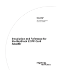
The Model 5399 Remote Access Concentrator Module is a dial-in remote
access server that supports mixed traffic, such as analog modems, V.120
ISDN Terminal Adapters, and devices supporting synchronous PPP. The
Model 5399 Remote Access Concentrator module is designed to operate
within the Bay Networks Lattice System 5000 Series Hub. Figure 1-1
illustrates a Model 5399.
WAN 2
WAN 1
Figure 1-1. Model 5399 Remote Access Concentrator Module
Nortel Networks 5399 Access Switch Hardware Installation Guide
1-1
Chapter 1
Introduction
Remote Network
Access
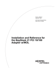
The Model 5399 provides remote network access to the following
networks (see Figure 1-2):
•
Novell Netware
•
TCP/IP
•
AppleTalk
DEC
IBM
UNIX
Corporate LAN
Ethernet
Model 5399 Remote
Access Concentrator
Novell
Server
Apple
Macintosh
Channelized T1,
Channelized E1 or
PRI ISDN Lines
Central
Office
Up to 60 Analog, V.120, or
Synchronous PPP Lines
Figure 1-2. The Model 5399 as a Remote Access Server
The Model 5399 also provides terminal to host connectivity to the
following:
•
1-2
UNIX hosts (using TCP/IP)
Nortel Networks 5399 Access Switch Hardware Installation Guide
Chapter 1
•
VMS hosts (using LAT)
•
IBM hosts (using TN3270)
Introduction
The Remote Access Concentrator supports Windows NT® host
tools. Remote Annex Server Tools for Windows NT® allows
you to boot and configure the Remote Access Concentrator on a
Windows NT® network. For more information, refer to the
Remote Annex Server Tools for Windows NT® User Guide.
Model 5399 Description
The Model 5399 is a Wide Area Network server capable of supporting
domestic ISDN, European ISDN, channelized T1, channelized E1, and
other channelized protocols. The Model 5399 can house up to 62 modems
to provide the flexibility of terminating calls originated by analog
modems, terminal adapters, and routers.
The Model 5399 Remote Access Concentrator module occupies one slot
in a System 5000 chassis.
Module Features
Processors
The module utilizes three 80486 DX2 clock-doubled processors,
operating at 64 MHz.
WAN Interfaces
These interfaces reside on the module and are accessible via an RJ48C
connector on the front panel. Each WAN interface is controlled by one
of the 80486 DX2 processors, which also controls the internal modems.
The WAN interfaces can accept channelized T1, channelized E1, or ISDN
PRI lines.
Memory
The module has 8 megabytes of main DRAM. An additional 4 megabytes
of DRAM is provided for each WAN interface controller.
Flash Memory
The module is equipped with 2 megabytes of Flash memory for image
storage.
Nortel Networks 5399 Access Switch Hardware Installation Guide
1-3
Chapter 1
Modems
Introduction
The Model 5399 Remote Access Concentrator Module can be configured
with up to 62 internal DSP-based digital modems. The modems are
dynamically downloaded with images to configure them to the
appropriate protocol. The modems are located on plug-in modem cards
installed on the module.
System 5000 Common Management Bus
The management section of the backplane is the common management
bus (CMB), a high-speed, multimaster, shared-memory communication
channel that connects all modules installed in the hub to one another and
to the supervisory module. The modules installed in the hub use the CMB
to acquire and distribute configuration and status information.
The supervisory module is an intelligent interface between the Model
5000 chassis and user-installed modules. The supervisory module
provides the following services to other modules across the CMB:
•
Maintains chassis component information and
environmental status
•
Stores the primary module configurations
•
Restores the module configuration after the module power is
cycled or the module is reset
The supervisory module also supports configuration terminal support
through the service port on the front panel of the chassis.
System 5000 Backplane Ethernet Segment Banks
The chassis backplane Ethernet bus consists of 12 Ethernet segments,
divided into two banks of six segments each: segments 1 through 6 and
segments 7 through 12. Each Model 5399 Remote Access Concentrator
module installed in the chassis can be configured to access one bank of
six segments, either segments 1 through 6 or segments 7 through 12. For
more information, see “Setting the Backplane Ethernet Segment” on page
2-3.
1-4
Nortel Networks 5399 Access Switch Hardware Installation Guide
Chapter 1
Introduction
Within a segment bank, the specific segment to which a Model 5399
Remote Access Concentrator module is connected is determined by
setting the segment selection DIP switch on the module. For more
information, see “Setting the Backplane Ethernet Segment” on page 2-3.
System 5000 Service Port Management
The service port, located on the front panel of the chassis, provides a
switched serial communication link between the service port and any
module in the hub, including the supervisory module. By connecting a
terminal to this port, you can change the configuration parameter values
for the Remote Access Concentrator installed in the hub.
For more information, see “Connecting a Service Port Terminal” on page
2-14, “Remote Access Concentrator Parameters” on page 2-18, and
“Installing the Model 5399 Remote Access Concentrator” on page 2-3.
Firmware and Software
Firmware
The Model 5399 Remote Access Concentrator’s ROM contains firmware
for performing power-up self-tests and loading operational code. A
non-volatile EEPROM stores the configuration parameters.
The Remote Access Concentrator can boot from the boot image in its
Flash memory or can boot an image received from a boot server on the
network.
ROM Monitor
The ROM monitor is an interactive command interpreter that is used to
define basic configuration parameter values. All of the information that
the Model 5399 Remote Access Concentrator needs to boot an operational
image is defined using the ROM monitor and its command set. ROM
Monitor commands are issued from a terminal connected to the service
port on the hub chassis. When the Remote Access Concentrator completes
its self tests, the service port terminal displays the ROM monitor prompt.
Using the ROM Monitor commands (see Chapter 3), you can:
Nortel Networks 5399 Access Switch Hardware Installation Guide
1-5
Chapter 1
Introduction
•
Modify and display a set of configuration parameters stored
in EEPROM.
•
Execute interactive diagnostic tests.
•
Receive information and statistics for the hardware
configuration and the network.
•
Boot the Remote Access Concentrator manually.
Once the Remote Access Concentrator has obtained a boot image and is
booted, the service port terminal leaves the ROM monitor and displays
the Console monitor (for more details, see Chapter 2).
Supported
Configurations
Watchdog Timer
1-6
You can self-boot the Model 5399 Remote Access Concentrator from the
image contained in its Flash ROM. The Remote Access Concentrator can
also obtain full operational code over the network from one of the
following devices:
•
UNIX host
•
Another Model 5399 Remote Access Concentrator
configured as a load server
•
NT host
The Model 5399 Remote Access Concentrator utilizes a watchdog timer
that is reset by the software at regular intervals. The watchdog timer
reboots the Remote Access Concentrator in the unlikely event of an
internal software error. This feature enables the Remote Access
Concentrator to run for long periods of time without intervention.
Nortel Networks 5399 Access Switch Hardware Installation Guide
Chapter 1
Introduction
Front Panel
The Model 5399 Remote Access Concentrator’s front panel consists of:
•
Annunciator LED
•
Segment Connection LEDs
•
Module Status LEDs
•
WAN 1 Network Status, Alarm, and Port Usage LEDs
•
WAN 2 Network Status, Alarm, and Port Usage LEDs
•
WAN 1 Port Connector
•
WAN 2 Port Connector
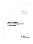
Figure 1-3 illustrates the Model 5399 Remote Access Concentrator’s
front panel. The front panel components are described in the following
paragraphs.
Nortel Networks 5399 Access Switch Hardware Installation Guide
1-7
Chapter 1
Introduction
Annunciator
Segment
Connection
LEDs
Module Status
LEDs
Network Status,
Alarm, and
Port Usage LEDs
WAN 2
WAN 2 Port
WAN 2
WAN 1
WAN 1
WAN 1 Port
Figure 1-3. Model 5399 Remote Access Concentrator Front Panel
Front Panel Components
Annunciator
1-8
The Annunciator backlights the model number of the module and
indicates, by its color, the operational condition of the module. Table 1-1
describes the Annunciator conditions.
Nortel Networks 5399 Access Switch Hardware Installation Guide
Chapter 1
Introduction
Table 1-1. Annunciator Conditions
Color
Operational Condition
Green
The module is performing normally.
Amber
Some portion of the module has failed, or the module is being
initialized.
Off
The module is not receiving +5 volt power, or the power level is
below the reset limit (4.65 volts).
Segment
Connection LEDs
The Segment Connection LEDs indicate which backplane Ethernet LAN
segments are being used. There are 12 green LEDs, labeled S1 through
S12, for the 12 Ethernet segments. When an LED is illuminated, it
indicates that the Model 5399 Remote Access Concentrator is connected
to the corresponding backplane Ethernet LAN segment; when off it
indicates that the corresponding backplane Ethernet LAN segment is not
connected.
Module Status LEDs
The Module Status LEDs are a group of five LEDs that display the status
of the activity of the Model 5399 Remote Access Concentrator. Table 1-2
describes the Module Status LEDs.
Table 1-2. Module Status LEDs
LED
Description
Init
Turns green when the Remote Access Concentrator begins the
initialization process after a power-up or reset. This is the first
LED that lights after power-up or reset. The Init LED turns off
after the diagnostics have successfully completed.
Unit
Turns green after the Remote Access Concentrator passes the
power-up diagnostics. Turns amber if the power-up diagnostics
fail.
Net
Turns green after the Remote Access Concentrator verifies that a
valid Ethernet connection exists.
Attn
Turns green when the Remote Access Concentrator requires
operator attention, that is, in monitor mode. Turns amber when the
diagnostic tests fail.
Nortel Networks 5399 Access Switch Hardware Installation Guide
1-9
Chapter 1
Introduction
Network Status and
Alarm LEDs
LED
Description
Load
Turns green when the Remote Access Concentrator is loading the
operational image or dumping a RAM image if there is a failure.
The LED turns amber if a load error is detected.
The Network Status and Alarm LEDs display network activity during
system operation. Table 1-3 describes the alarms. There are two sets of
Network Status and Alarm LEDs, one set for each WAN port.
Technical Support personnel can use this information to diagnose
problems.
Table 1-3. Network Status and Alarm LEDs
1-10
Alarm
Description
TEST
The network TEST indicator is ON (amber) when the WAN
Interface is looped back. Loopback tests are activated either
locally by the user or by the telephone company.
SYNC
The SYNC indicator is ON (green) when the WAN interface is
properly synchronized with the received network signal and is
receiving proper framing information.
LOS
The LOS indicator is ON (amber) when the WAN interface is
detecting invalid synchronization pulses on the network
interface receiver. When a LOS condition exists, the Remote
Access Concentrator transmits a YELLOW alarm to the
remote system.
RED
The RED alarm indicator is ON (amber) during a locally
detected carrier failure. During the RED alarm condition, a
YELLOW alarm is transmitted across the telephone network.
YELLOW
The YELLOW alarm indicator is ON (amber) when receiving
a YELLOW alarm condition from the telephone network. This
indicates a failure detected at the other end of the link (the
Central Office).
BLUE
The BLUE alarm indicator is ON (amber) when receiving an
unframed, all-ones Alarm Indication Signal (AIS) from the
network. This condition exists upon a loss of originating
signal, or when any action is taken that would cause a signal
disruption.
Nortel Networks 5399 Access Switch Hardware Installation Guide
Chapter 1
Introduction
Port Usage LEDs
The Port Usage LEDs, labelled 25%, 50%, 75%, and 100%, indicate the
approximate percentage of B channels that are being utilized. There are
two sets of Port Usage LEDs, one set for each WAN Port. These LEDs
are normally green. If all available B channels are in use, they turn amber
until at least one call disconnects.
WAN Interface Ports
The two WAN interface ports provide access to Channelized T1,
Channelized E1, or ISDN PRI lines. The WAN Interface ports come with
8-pin, RJ48C jacks for attaching the T1, E1 or ISDN cable connectors.
Nortel Networks 5399 Access Switch Hardware Installation Guide
1-11
Chapter 1
Introduction
Physical Characteristics
The Model 5399 Remote Access Concentrator module has the following
characteristics:
•
Dimensions:
Height: 19 in. (47.5 cm)
Width: 1.2 in. (3 cm)
Depth: 11 in. (27.5 cm)
•
Weight:
10 lbs (4.5 kg).
•
•
1-12
Electrical Specifications:
•
Power Consumption: 90 W at 48 VDC
•
Thermal Rating: 307 BTU/hr maximum
Environment:
•
Operating temperature: 5° to 40°C.
•
Non-operating temperature: -25° to 65°C.
•
Operating humidity: 85% maximum relative humidity,
non-condensing.
•
Non-operating humidity: 95% maximum relative
humidity, non-condensing.
•
Operating shock: 10G peak 1/2 sine wave, 11 ms
duration.
•
Operating vibration: random vibration 1.2 *10-3 G2/Hz,
12 to 198 Hz.
•
Operating altitude: 0 to 4,000 meters.
•
Storage altitude: 0 to 15,000 meters.
Nortel Networks 5399 Access Switch Hardware Installation Guide
Chapter 1
•
•
•
Introduction
Transportation vibration and shock: NSTA project 1A
standard in shipping container.
Approvals:
•
Meets safety requirements of Underwriters Laboratories
for UL 1950 and CSA C22.2 No. 950.
•
Meets EMI requirements of FCC Class A and EN55022
Class A with shielded and unshielded cables.
•
Meets US and Canadian Telcom requirements per FCC
Part 68 and IC CS-03.
MTBF:
50,000 hrs. (estimated), calculated @ 25°C (Mil Std 217).
•
Front clearance requirement (for connectors and cables):
6 in. (15 cm).
Nortel Networks 5399 Access Switch Hardware Installation Guide
1-13
Chapter 2
Installing the Model 5399
Remote Access Concentrator
Module
T
his chapter describes how to install your Model 5399 Remote Access
Concentrator Module hardware and software, and connect it to a System
5000 Hub. This chapter provides the following information:
•
Before You Begin
•
Installing the Model 5399
•
Testing the Installation
•
Connecting a WAN Interface
•
Connecting a Service Port Terminal
•
Initial Setup and Using the ROM Monitor
•
Auto-initializing the ROMs
•
Installing the Software and Loading the Operational Image
•
Self-booting the Model 5399
•
Invoking the Console Monitor
Before you Begin
To successfully install the Model 5399, you need:
•
A 3/16-inch flat-tip screwdriver
•
An antistatic mat and wrist strap (attached to an antistatic
leash)
•
A service port terminal and cable
•
A valid IP address
Nortel Networks 5399 Access Switch Hardware Installation Guide
2-1
Chapter 2
Installing the Model 5399 Remote Access Concentrator Module
•
An appropriate subnet mask
•
A host with Model 5399 software installed (if not booting
from FLASH memory)
The Model 5399 can receive its operational image from any one of these
sources:
•
A UNIX host running erpcd
•
FLASH memory (self boot)
•
Another Model 5399 configured as a boot host
•
Any host supporting TFTP
•
A Windows NT host running erpcd
The Remote Access Concentrator supports Windows NT® host
tools. Remote Annex Server Tools for Windows NT® allows
you to boot and configure the Remote Access Concentrator on a
Windows NT® network.
Table 2-1 outlines the different configurations the Model 5399 supports.
Table 2-1. Model 5399 Configuration Options
2-2
Device on which the
Operational Software and
Image is installed
Model 5399 Must Input Device used to
Be Connected to Enter Basic
the Network
Configuration
Parameter Values
UNIX Load Host
Yes
Service Port Terminal
Another Model 5399
configured as a load server
Yes
Service Port Terminal
Self-boot (from the image
contained in Flash memory)
No
Service Port Terminal
Windows NT® host
Yes
Service Port Terminal
Nortel Networks 5399 Access Switch Hardware Installation Guide
Chapter 2
Installing the Model 5399 Remote Access Concentrator Module
Installing the Model 5399 Remote Access Concentrator
This section describes how to install the Model 5399 Remote Access
Concentrator Module in a System 5000 Hub. Installing the Model 5399
involves seating the backplane connectors to the Model 5000 Hub
backplane and verifying the installation.
Preparing for Hardware Installation
This section explains how to prepare the Model 5399 for installation in
the chassis.
System 5000 equipment uses electronic components that are
sensitive to static electricity. Static discharge from your clothing
or other fixtures around you can damage these components. You
should take all possible precautions to prevent static discharge
damage when working with printed circuit boards. If possible,
place all printed circuit boards on an antistatic mat until you are
ready to install them. If you do not have an antistatic mat, wear
a discharge leash to free yourself of static before touching any
of the printed circuit boards, or free yourself of static by
touching the metal of the chassis before handling a printed
circuit card.
Setting the Backplane Ethernet Segment
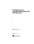
Figure 2-1 shows the locations of the configuration jumper and DIP
switch that you must set to select an Ethernet segment. They are:
•
Ethernet segment bank selector (J5)
•
Ethernet segment selection DIP switch (S1)
Nortel Networks 5399 Access Switch Hardware Installation Guide
2-3
Chapter 2
Installing the Model 5399 Remote Access Concentrator Module
Jumper
Card
DIP
Switch
S1
ON
1
2
3
4
5
6
Figure 2-1. Model 5399 Jumper and Connector Locations
Ethernet Segment Bank Selector
The Ethernet segment bank selector (see Figure 2-1), consisting of three
rows of 20 pins (labeled J5, J21 and J22) and a jumper card, determines
whether the module connects to Ethernet segments 1 through 6 or
segments 7 through 12 at power up. When the jumper card is installed on
the two rows of pins nearest the front of the module (using J21), the
module has access to segments 1 through 6 (the factory default setting);
when the jumper card is installed on the two rows of pins nearest the back
of the module (using J22), the module has access to segments 7 through
12.
2-4
Nortel Networks 5399 Access Switch Hardware Installation Guide
Chapter 2
Installing the Model 5399 Remote Access Concentrator Module
When the jumper card is installed between J5 and J21, the
printed circuit card handle is nearest the front of the module. To
install the jumper card between J5 and J22, remove the jumper
card, rotate it 180 degrees (so that the printed circuit card handle
is nearest the back of the module) and push it onto the pins (see
Figure 2-1).
The specific segment connection for the module is determined by the
segment selection DIP switch (described in the next section).
Network management software cannot override the bank
selector setting. The setting (segments 1–6 or 7–12) can only be
set while the module is outside the chassis.
Segment Selection DIP Switch
DIP switch S1 on the module (see Figure 2-1) is used to set the default
segment selections. Segment selection DIP switch settings are listed in
Table 2-2. Turning a DIP switch number ON selects a particular segment
within the Ethernet segment bank. For example, turning on DIP switch
number 1 selects either segment 1 or 7, depending on the position of the
Ethernet segment bank selector jumper card.
If no DIP switch numbers are turned on, the unit defaults to
Segments 1 or 7 (depending on the position of the Ethernet
segment bank selector jumper card).
Nortel Networks 5399 Access Switch Hardware Installation Guide
2-5
Chapter 2
Installing the Model 5399 Remote Access Concentrator Module
Table 2-2. Segment Selection DIP Switch Settings
DIP Switch S1 Jumper Card Connects
Jumper Card Connects J5,
Switch Number J5, J21 (Segment Bank 1-6) J22 (Segment Bank 7-12)
1 (default)
Segment 1
Segment 7
2
Segment 2
Segment 8
3
Segment 3
Segment 9
4
Segment 4
Segment 10
5
Segment 5
Segment 11
6
Segment 6
Segment 12
Network management software can override this DIP switch
setting, so an installed module may connect to a different
segment (within the segment bank) than is indicated by the DIP
switch setting.
Installing the Module into the Hub
To install and secure the module into the System 5000 Hub, follow these
steps:
2-6
1.
Remove the blank filler panel from the chassis slot where
you intend to install the module.
2.
Verify that the module jumpers are set correctly (see
“Setting the Backplane Ethernet Segment” on page 2-3).
3.
Extend the inserter/extractor levers to their fully extended
positions (see Figure 2-2).
Nortel Networks 5399 Access Switch Hardware Installation Guide
Chapter 2
Installing the Model 5399 Remote Access Concentrator Module
Figure 2-2. Inserter/Extractor Lever
4.
Align the top and bottom edges of the module in the card
guides of the target slot, and push the module into the
chassis until the inserter/extractor levers just engage the
front edges of the chassis (see Figure 2-3).
Nortel Networks 5399 Access Switch Hardware Installation Guide
2-7
Chapter 2
Installing the Model 5399 Remote Access Concentrator Module
Figure 2-3. Inserting the Module
5.
Seat the module backplane connectors by simultaneously
pushing the inserter/extractor levers toward the center of
the module front panel (see Figure 2-4).
When the front panel of the module is flush with the front of the
chassis, the module backplane connectors are properly seated.
2-8
Nortel Networks 5399 Access Switch Hardware Installation Guide
Chapter 2
Installing the Model 5399 Remote Access Concentrator Module
Figure 2-4. Seating Module Connectors
6.
Tighten the captive retaining screws at both ends of the
module front panel.
Nortel Networks 5399 Access Switch Hardware Installation Guide
2-9
Chapter 2
Installing the Model 5399 Remote Access Concentrator Module
Testing the Installation
After installing and connecting the Remote Access Concentrator, verify
that you have performed the installation correctly by observing the LED
indicators and system operation displays on the front panel of the Remote
Access Concentrator (see Figure 2-5).
Annunciator
Segment
Connection
LEDs
Module Status
LEDs
Network Status,
Alarm, and
Port Usage LEDs
WAN 2
WAN 2 Port
WAN 2
WAN 1
WAN 1
WAN 1 Port
Figure 2-5. Module LED Display
2-10
Nortel Networks 5399 Access Switch Hardware Installation Guide
Chapter 2
Installing the Model 5399 Remote Access Concentrator Module
The Model Remote Access Concentrator performs a series of
self-test diagnostics each time it is reset or powered up. These
tests take about a minute to complete and cannot be deactivated.
While these tests are running, the annunciator remains amber.
The annunciator changes to green upon successful test
completion. For information about possible error conditions, see
Chapter 4.
LED Indicators
When the Remote Access Concentrator is operating correctly, the
front-panel LEDs (see Figure 2-5) should appear as follows:
•
Annunciator: The annunciator should be green. If the
annunciator remains amber after completing the self-tests,
refer to Chapter 4.
•
Segment Connection LEDs: A steady green indicates which
Ethernet LAN segment the module is using.
•
Module Status LEDs:
•
Init: Turns green when the module begins the
initialization process after a power-up or reset. Typically,
this is the first LED that lights after power-up. The Init
LED turns off after the initial diagnostics have
successfully completed.
•
Unit: Turns green after the module passes the power-up
diagnostics. If the Unit LED turns amber, refer to
Chapter 4.
•
Net: Turns green after the module verifies that a valid
Ethernet connection exists.
Nortel Networks 5399 Access Switch Hardware Installation Guide
2-11
Chapter 2
Installing the Model 5399 Remote Access Concentrator Module
•
•
•
Attn: The Attn LED should be off. The Attn LED turns
green if the Remote Access Concentrator is in Monitor
Mode. If the Attn LED is amber or flashing, one of the
following failures has occurred:
•
Hardware failure. Contact technical support.
•
Network or network interface failure. Error message
displays on the terminal. If a network or network
interface failure occurs, typing q accesses the ROM
Monitor prompt. Check the network connection and
then see the section “net” on page 3-19.
Load: Turns green when the Remote Access
Concentrator is loading the operational image or
dumping a RAM image if there is a failure.
Verify that the hub front-panel LEDs are properly
illuminated.
If the LEDs do not light in the proper manner, or if the system operation
displays indicate problems, see Chapter 4 for more details.
Connecting a WAN Interface
Be sure to properly configure the interface before connecting
the cable. Some switch types will disable lines connected to an
improperly configured device. See the Model 5399 Remote
Access Concentrator Module Network Administrator’s Guide
for details.
A WAN Interface is used to connect the Remote Access Concentrator to
channelized T1, channelized E1, or ISDN PRI lines. Follow the
instructions in this section to connect the line to the WAN Interface port.
Observe handling precautions: digital telecommunications
cable(s).
2-12
Nortel Networks 5399 Access Switch Hardware Installation Guide
Chapter 2
1.
Installing the Model 5399 Remote Access Concentrator Module
Plug the cable into the WAN Interface port located on the
front panel of the Remote Access Concentrator (Figure 2-6).
When the connector clicks into place, the connection is secure.
Port Pins and Signals on page A-1 describes the WAN Interface
port’s signal/pin allocation.
For T1 applications, the Remote Access Concentrator
utilizes an internal Channel Service Unit (CSU). An
internal CSU is not used in E1 applications.
Figure 2-6. Connecting a WAN Interface
Nortel Networks 5399 Access Switch Hardware Installation Guide
2-13
Chapter 2
Installing the Model 5399 Remote Access Concentrator Module
Connecting a Service Port Terminal
If your network does not include a BOOTP or RARP server, you must
connect a terminal to the service port on the System 5000 chassis front
panel and manually configure the Remote Access Concentrator before
booting.
To configure the Remote Access Concentrator through the chassis service
port, you need:
•
•
2-14
An ascii terminal or a portable computer with a serial port
and the ability to emulate an ascii terminal. The terminal
should be set up for:
–
9600 bps (default)
–
8 data bits
–
No parity
–
1 stop bit
–
No flow control
–
ASCII
An RS-232 modem cable with a female DB-9 connector to
connect to the service port on the chassis front panel. The
other end of the cable must have a connector appropriate to
the serial port on your computer or terminal. (Most terminals
or computers use a male DB-9 or DB-25 connector.) The
cable should use the pin assignments in Table 2-3.
Nortel Networks 5399 Access Switch Hardware Installation Guide
Chapter 2
Installing the Model 5399 Remote Access Concentrator Module
Table 2-3. Service Port Pin Assignments
Terminal
DB-9
DB-25
Function
To Service Port Function
DB-9 Pins
2
3
Receive data
2
Transmit data
3
2
Transmit data
3
Receive data
5
7
Signal ground
5
Signal ground
RS-232 signals on other pins, such as DTR, CTS, and CD, are
ignored.
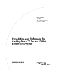
Connecting the Terminal
To connect the terminal to the service port, follow these steps:
1.
Connect the terminal (or a computer in terminal emulation
mode) to the chassis service port with the RS-232 cable.
2.
Press
Esc
to display the Slot Selection menu.
The Slot Selection menu (Figure 2-7) shows the system date
and time, lists the modules installed in the chassis by slot
number, and lists the available commands.
Nortel Networks 5399 Access Switch Hardware Installation Guide
2-15
Chapter 2
Installing the Model 5399 Remote Access Concentrator Module
Model 5399 Slot Selection Menu 01/15/97, 10:19:32 AM
Slot 1
1
2
3
4
5
6
7
8
9
10
11
12
13
14
Status:
On-line
Configuring
Other
(removed)
Off-line
Booting
On-line
Module Description:
5310 Ethernet NMM
5308 Ethernet Host
5308 Ethernet Host
5308 Ethernet Host
5308 Ethernet Host
5308 Ethernet Host
5308 Ethernet Host
Off-line
5399 Remote Access Concentrator
c - Connect to slot (Press CTRL-T to break connection)
s - Select Supervisory Module Main Menu r - Reset module
Enter selection:
Figure 2-7. Slot Selection Menu
Use this menu to reset the Remote Access Concentrator. For
more information, see “Auto-initializing the IP Address
Parameters” on page 2-23.
2-16
Nortel Networks 5399 Access Switch Hardware Installation Guide
Chapter 2
Installing the Model 5399 Remote Access Concentrator Module
Initial Setup and Using the ROM Monitor
After installing the Remote Access Concentrator software on the file
server host, collect the following information, which is required to
determine the unit’s boot parameters:
•
The location (directory path) of the download files on the
host (tftp only).
•
Whether the Remote Access Concentrator and host are on
the same subnet or separated by one or more routers.
•
Whether the host going to use tftp or erpcd (requires a
UNIX or Windows NT® host) to serve the Remote Access
Concentrator download code.
The Remote Access Concentrator needs these parameters to perform an
initial boot when loading the software. Enter these parameters into the
EEPROM using the ROM monitor commands, which are accessed
through a service port terminal. See Chapter 3 for more information about
these commands.
The Remote Access Concentrator supports the Bootstrap Protocol
(BOOTP) and the Reverse Address Resolution Protocol (RARP) which
can be used to obtain some of the information listed. If you have a host
running BOOTP or RARP to serve the Remote Access Concentrator the
information, the server will boot without user intervention. For more
information about using these protocols, see “Auto-initializing the IP
Address Parameters” on page 2-23.
The Remote Access Concentrator supports Windows NT® host
tools. Remote Annex Server Tools for Windows NT® allows
you to boot and configure the Remote Access Concentrator on a
Windows NT® network. For more information, see the Remote
Annex Server Tools for Windows NT® User Guide.
Nortel Networks 5399 Access Switch Hardware Installation Guide
2-17
Chapter 2
Installing the Model 5399 Remote Access Concentrator Module
Remote Access Concentrator Parameters
The Remote Access Concentrator requires that you set certain parameters
from the ROM monitor before booting the unit from a host. Once the
Remote Access Concentrator is booted, you can change these parameters
using the na utility. Any changes to these parameters will require the unit
to be rebooted to take effect. Table 2-4 provides a brief description of
these parameters.
Table 2-4. Server Parameters
2-18
Parameter
Description
Internet address
A unique 32-bit universal identifier that is
specified in dotted-decimal notation.
Subnet mask
Defines which portion of the Internet address
is the network (all ones), the subnet (all ones),
and the host (all zeros) address.
Preferred load host address
The Internet address of the host from which
you want to boot.
Load/dump gateway
Internet address
The Internet address of the router, for which
you will be prompted, if the preferred load
host is on a different network.
Broadcast address
An Internet address with a host id of all ones
(or all zeros for support of older 4.2 BSD
systems) to which all hosts on a particular
subnet will respond.
Type of IP encapsulation
Specifies the method for accessing the
physical and network layer of the transmission
media. The default is: ethernet (for DIX
Ethernet-II). This parameter can also be set to
ieee802 (also referred to as LLC/SNAP).
Broadcast flag
Determines whether the Remote Access
Concentrator will broadcast for a load host if it
doesn’t have one.
Nortel Networks 5399 Access Switch Hardware Installation Guide
Chapter 2
Installing the Model 5399 Remote Access Concentrator Module
Initializing the Remote Access Concentrator
This section describes how to set up the Remote Access Concentrator,
make the connection to the System 5000 Hub for the first time, and enter
Monitor Mode to configure the module.
To initialize the Remote Access Concentrator and enter Monitor Mode:
1.
Use a terminal connected to the chassis service port to verify
that the Remote Access Concentrator is operating properly.
The Slot Selection menu is displayed. The Remote Access
Concentrator should be listed next to the slot number in which it
is installed.
2.
Reset the Remote Access Concentrator by typing r and then
entering the slot number of the chassis that contains the
server.
The following prompt is displayed:
Are you sure you want to RESET this module? (Y/N):
3.
Answer the question by entering y.
4.
Within 10 seconds, connect to the Remote Access
Concentrator by typing c and then entering the slot number
of the chassis that contains the server.
5.
Wait for the following prompt:
To enter “Monitor Mode” please depress the SPACE key
within 10 seconds.
The prompt counts down from 10 seconds.
Nortel Networks 5399 Access Switch Hardware Installation Guide
2-19
Chapter 2
Installing the Model 5399 Remote Access Concentrator Module
6.
Press the space bar within 10 seconds.
After a few seconds, the following message is displayed:
Monitor Mode selected, please wait for Confidence tests
to complete.
After about a minute, the following message is displayed,
followed by the monitor prompt:
System Reset - Entering Monitor Mode
monitor::
7.
If you want to clear out the stored parameters from a
previously used slot (reset the hub slot), continue on with
Step 8. If you do not want to reset the hub slot (if, for
example, you are performing a hot swap), skip to Step 16.
8.
On the service port terminal, press
display the Slot Selection menu.
9.
Press s.
Enter
then
Control
-T to
The Supervisory Module Main Menu is displayed.
10. Press m to select the Module Information menu.
The following prompt is displayed:
Enter slot # (1-14):
11. Enter the slot number of the module you want to boot.
The module information and status are displayed and you are
prompted to reset the module, set the module configuration to
default, or return to the previous menu.
12. Press d to select the module configuration default.
The following message is displayed:
Are you sure you want to set module DEFAULT
configuration? (Y/N):
2-20
Nortel Networks 5399 Access Switch Hardware Installation Guide
Chapter 2
Installing the Model 5399 Remote Access Concentrator Module
13. Press y.
The Module Information menu is displayed.
14. Press
Escape
twice.
The Slot Selection menu is displayed.
15. Press c and the slot number.
16. Verify the Remote Access Concentrator hardware
configuration by typing config and pressing Return at the
monitor prompt.
The screen display looks similar to this:
REVISION/CONFIGURATION INFORMATION
ROM Software Rev: 1110
Board ID: 64
CPU Type: 486DX2
Memory size: 8 Meg
Flash size: 2 Meg
Board Type: 5399
Ethernet Address: 00-80-2d-xx-xx-xx
EEPROM size: 65504
Flash ID:0089
WAN 1: PRI E1 ETSI
WAN 2: PRI E1 ETSI
Revision: VERSION A MGR=1.159
Revision: VERSION A MGR=1.159
SLC 1
SLC SRAM Size: 128 K
Modem Count: 31
Modem Rev: 0
SLC 2
SLC SRAM Size: 128 K
Modem Count: 31
Modem Rev: 0
Hub Slot
9
Hub CMB HW Rev
01
Hub EE Rev
0.0
Hub EE Seg Sel
N/A
Hub Jmpr Seg Sel
00
Nortel Networks 5399 Access Switch Hardware Installation Guide
2-21
Chapter 2
Installing the Model 5399 Remote Access Concentrator Module
17. To verify and record the unit’s Ethernet address, type addr
-d and press Return at the monitor prompt:
The screen display looks similar to this:
monitor:: addr -d
Ethernet address (hex): 00-80-2d-XX-XX-XX
Internet address: <uninitialized>
Subnet mask: 255.255.0.0
Broadcast address: 0.0.0.0
Preferred Load Host address: <any host>
Preferred Dump Host address: 0.0.0.0
Load/Dump Gateway address: 0.0.0.0
Type of IP packet encapsulation: <ethernet>
Load Broadcast: Y
18. Verify that the Remote Access Concentrator is on-line by
entering the net command. The following prompt appears:
Enter Segment to be used [1]:
A “pass” or “fail” message is displayed. If fail is displayed, try
verifying the network from another device.
Once the Remote Access Concentrator is on-line, you can download the
image software to the server (see “Installing the Operational Software
and Loading the Image” on page 2-32).
2-22
Nortel Networks 5399 Access Switch Hardware Installation Guide
Chapter 2
Installing the Model 5399 Remote Access Concentrator Module
Booting the Remote Access Concentrator
You can boot the operational software by downloading the image from a
host system or another Model 5399 Remote Access Concentrator, or by
using the image contained in Flash memory (self-boot). However, before
actually booting the unit, you must first initialize the IP address
parameters either manually or by using the auto-initialize feature. The
following sections describes the two methods of initializing the IP address
parameters, and the various boot methods.
Auto-initializing the IP Address Parameters
The Remote Access Concentrator is distributed without an IP address or
preferred load host defined in ROM. When the device is booted, the
Remote Access Concentrator attempts to auto-initialize itself using
BOOTP (bootstrap protocol) and RARP (Reverse Address Resolution
Protocol).
This method of initializing the IP address parameters is
generally done when booting from a host system (not when
self-booting).
The Remote Access Concentrator supports the BOOTP and RARP
protocols. Use these protocols to obtain boot information from a UNIX
host without requiring any manual set-up on the Remote Access
Concentrator.
•
BOOTP allows a diskless client to determine its IP address,
the IP address of the server, and the name of the file to be
loaded into memory.
•
RARP maps a hardware address into an IP address.
The ROMs invoke this system of acquiring boot information when a boot
is initiated and the Remote Access Concentrator is not initialized. Under
this condition, the Remote Access Concentrator first tries to get boot
information via BOOTP or RARP.
Nortel Networks 5399 Access Switch Hardware Installation Guide
2-23
Chapter 2
Installing the Model 5399 Remote Access Concentrator Module
If all requests fail, the Remote Access Concentrator will return to the
ROM monitor (if in Test mode) or continue the auto-initializing procedure
indefinitely (if in normal mode).
BOOTP
For a successful BOOTP retrieval, a bootpd must be running on a host
on the same subnet as the Remote Access Concentrator (or have a
correctly-configured router on the same subnet that supports BOOTP
forwarding) and must have the appropriate information in the bootptab
file. The Remote Access Concentrator’s BOOTP implementation adheres
to rfc951, rfc1048, and rfc1084. A sample bootptab file entry used to
initialize the Remote Access Concentrator named terminator looks like
this:
remoteannexdefault:\
:sm=255.255.255.0:gw=132.245.22.66:\
:hn:vm=auto:to=-18000:
terminator:\
:ht=1:ha=00802d004879:ip=132.245.22.226:\
:tc=remoteannexdefault:
In the previous example:
2-24
•
sm is the subnet mask.
•
gw is the load/dump gateway address.
•
vm is the Vendor Magic Cookie.
•
ht is host type (1=Ethernet).
•
ha is the Remote Access Concentrator’s hardware address
(Ethernet Address).
•
ip is the Remote Access Concentrator’s Internet Address.
Nortel Networks 5399 Access Switch Hardware Installation Guide
Chapter 2
Installing the Model 5399 Remote Access Concentrator Module
When the Remote Access Concentrator receives a BOOTP response with
the sm, gw, and ip set, it sets the respective parameters: subnet_mask,
load_dump_gateway, and inet_addr. The Vendor Magic Cookie must
be set to auto. This indicates that bootpd should respond to the client
(Model 5399 Remote Access Concentrator in this case) with whatever
format the client requests; the Model 5399 Remote Access Concentrator
(client) always makes requests with the Vendor Magic Cookie set to
99.130.83.99.
The bootpd adds the address of the host on which it is running as the
Server Address in the bootp response message. The ROMs use the Server
Address as the preferred load host and store it in the pref_load_addr
parameter.
The host running bootpd (the preferred load host) must also be
running erpcd or tftpd.
RARP
If the Remote Access Concentrator does not receive a successful BOOTP
response, it uses RARP to get the boot information. For a successful
RARP retrieval, TCP/IP must be running on a host that is on the same
subnet as the Remote Access Concentrator, and the host’s ARP table must
be initialized with the Remote Access Concentrator’s Internet and
Ethernet addresses (see the arp man page for arp –s).
The only boot information that RARP provides is the Remote Access
Concentrator’s Internet address. The ROMs save this information in the
inet_addr parameter. The ROMs use default information for the subnet
mask and preferred load host. This means the ROMs will broadcast their
requests.
Nortel Networks 5399 Access Switch Hardware Installation Guide
2-25
Chapter 2
Installing the Model 5399 Remote Access Concentrator Module
The host serving the Remote Access Concentrator its boot information
must be running on the same subnet as the Remote Access Concentrator
because the Remote Access Concentrator broadcasts BOOTP and RARP
queries using the “this network” IP address, 255.255.255.255.
If BOOTP and RARP fail, the Remote Access Concentrator transmits an
IPX Advertisement Request for Service.
If all requests fail, the Remote Access Concentrator returns to the ROM
monitor (if in Test Mode) or continues the auto-initializing procedure
indefinitely (if in Normal Mode).
Manually Initializing the IP Address Parameters
To configure the Remote Access Concentrator for your specific needs,
the IP address parameters can be manually initialized by performing the
following steps:
1.
Enter the addr command at the monitor prompt.
The following prompt is displayed:
Enter Internet address::
2.
Enter the IP address for the Remote Access Concentrator.
You are prompted to enter the server subnet mask, preferred
load host, preferred dump host, IP packet encapsulation, and
load broadcast flag. The defaults are listed after each prompt.
3.
2-26
Modify the parameter next to each prompt, or press
retain the current setting.
Nortel Networks 5399 Access Switch Hardware Installation Guide
Enter
to
Chapter 2
Installing the Model 5399 Remote Access Concentrator Module
Booting Using BFS
Perform the following steps to boot the Remote Access Concentrator
using BFS:
1.
Initialize the IP address parameters using either the
auto-initialize or manual initialize method.
The auto-initialization method is described in “Auto-initializing
the IP Address Parameters” on page 2-23. The manual
initialization method is described in “Manually Initializing the
IP Address Parameters” on page 2-26.
2.
Enter the boot command.
If you do not enter a file name with the command, you are
prompted for one (the default file name is displayed at the
prompt: oper.64.enet). Press Enter to boot using the default file
name.
The following example shows a typical screen display for a BFS
boot using erpcd on UNIX or Windows NT:
Enter boot file name[oper.64.enet]::
Waiting for CMB Config Block Info...
Requesting boot file ”oper.64.enet”.
Unanswered requests shown as ’?’,transmission errors
as ’*’.
Requesting boot from 192.9.200.88 via Ethernet...
Booting BFS file using open delay of 8
Booting BFS file from 192.9.200.88
Header received OK. Received data blocks shown as ’.’.
. . . . . . . . . . . . . . . . . . . . . . . . . . .
. . .. . . . . . . . . . . . . . . . . . . . . . . .
. . . . . . . . . . . .. . . . . . . . . . . ? . . .
. . . . . . . . . . . . . . . . . . . . . . . . . . .
. . . . . . . . . . . . . . . . . . . . . * . . . . .
. . . . . . . . . . . . . . . . . . . . . . . * . . .
. . . . . . . . . . . . . . . . . . . . . . . . . . .
. . . . . . . . . . . . . . . . . . ? . . . . . . . .
. . . . . . . . . . . . . . . . . . . . . . . . . . . . . . EOF
Nortel Networks 5399 Access Switch Hardware Installation Guide
2-27
Chapter 2
Installing the Model 5399 Remote Access Concentrator Module
The download takes between 30 and 60 seconds for a Model 5399 Remote
Access Concentrator booting over the local network. After the download
is complete, the Power, Unit, and Net LEDs remain on. If these LEDs do
not remain on (indicating a problem), see Chapter 4.
Once the Remote Access Concentrator is booted, Monitor Mode is no
longer operational. The Remote Access Concentrator is up and running,
and the following message is displayed:
Console monitor ready; Press CR to start
2-28
Nortel Networks 5399 Access Switch Hardware Installation Guide
Chapter 2
Installing the Model 5399 Remote Access Concentrator Module
Booting Using TFTP
The procedures detailed in this section assume that your TFTP daemon
(tftpd) is started in /etc/inetd.conf (or other appropriate directory on
your system) with a configuration line similar to this:
tftp dgram udp wait root /usr/etc/in.tftpd in.tftpd
-s/tftpboot
If you leave off the -s /tftpboot, a chroot will not be done,
and your system will be insecure.
To set up directories and files, and use TFTP to boot the Remote Access
Concentrator, follow these steps:
1.
Initialize the IP address parameters using either the
auto-initialize or manual initialize method.
The auto-initialization method is described in “Auto-initializing
the IP Address Parameters” on page 2-23. The manual
initialization method is described in “Manually Initializing the
IP Address Parameters” on page 2-26.
2.
Enter the image command at the monitor prompt.
As prompted, enter the following information:
•
Appropriate boot image name
•
Boot directory
•
Dump filename
The default image file name is: oper.64.enet
The following example shows how the image command is used
to set up a Remote Access Concentrator boot from the /tftpboot/
annex/ directory. When you enter the load directory name, make
sure you end the pathname with a slash character.
Nortel Networks 5399 Access Switch Hardware Installation Guide
2-29
Chapter 2
Installing the Model 5399 Remote Access Concentrator Module
Image name: <invalid or uninitialized> Default:
“oper.64.enet”
Enter Image name::oper.64.enet
Image name: “oper.64.enet”
TFTP load directory:
Enter TFTP load directory::/annex
TFTP Dump path/filename: <uninitialized> Default :
“dump.134.117.6.34”
Enter TFTP Dump path/filename::/annex/mydumpfile
Using current TFTP Dump path/filename.
monitor::
3.
Issue the following commands to prepare the tftp dump file.
touch /tftpboot/annex/mydumpfile
chmod 622 /tftpboot/annex/mydumpfile
4.
Enter the boot command.
The boot command display looks similar to this:
Enter boot file name[oper.64.enet]::
Waiting for Config Block Info...
Requesting boot file ”oper.64.enet”.
Unanswered requests shown as ’?’,transmission errors
as ’*’.
Requesting boot from 192.9.200.88 via Ethernet...
Booting BFS file using open delay of 8?
Booting TFTP file using open delay of 8
Booting TFTP file from 192.9.200.88
Header received OK. Received data blocks shown as ’.’.
. . . . . . . . . . . . . . . . . . . . . . . . . . .
. . . . . . . . . . . . . . . . . . . . . . . . . . .
. . . . . . . . . . . . . . . . . . . . . . . . . . .
. . . . . . . . . . . . . . . . . . . . . . . . . . .
. . . . . . . . . . . . . . . . . . . . . . . . . . .
. . . . . . . . . . . . . . . . . . . . . . . . . . .
. . . . . . . . . . . . . . . . . . . . . . . . . . .
. . . . . . . . . . . . . . . . . . . . . . . . . . .
. . . . . . . . . . . . EOF
Once the Remote Access Concentrator is booted, Monitor Mode is no
longer operational. The Remote Access Concentrator is up and running,
and the following message is displayed:
Console monitor ready; Press CR to start.
2-30
Nortel Networks 5399 Access Switch Hardware Installation Guide
Chapter 2
Installing the Model 5399 Remote Access Concentrator Module
Self-booting the Remote Access Concentrator
The Remote Access Concentrator comes equipped with Flash memory
that contains an operational image you can use to self-boot the module.
To self-boot your Remote Access Concentrator, perform the following
steps:
1.
Initialize the IP address parameters using the manual
initialize method.
The manual initialization method is described in “Manually
Initializing the IP Address Parameters” on page 2-26.
2.
Enter the sequence command at the monitor prompt.
The following prompt is displayed:
Enter interface sequence [net]::
3.
Enter self, net as the sequence.
The monitor prompt is displayed.
4.
Enter the boot command at the monitor prompt.
The display looks similar to this:
monitor:: boot
Waiting for CMB Config Block Info...
Requesting default boot file “OPER_64_ENET.SYS” for
MOP/VMS\ loads and “oper.64.enet” for all other
protocols. Unanswered requests shown as ‘?’,
transmission errors as ‘*’.
Booting file: “OPER_64_ENET.SYS” from SELF
Loading image from SELF ...
.................................................
Load Completed
The self-boot takes 10 seconds to complete. Once the Remote
Access Concentrator has booted, Monitor Mode is no longer
active.
Nortel Networks 5399 Access Switch Hardware Installation Guide
2-31
Chapter 2
Installing the Model 5399 Remote Access Concentrator Module
Booting from a Windows NT® Host
To boot the Remote Access Concentrator from a Windows NT ® host, you
must have Remote Annex Server Tools for Windows NT ® installed.
Remote Annex Server Tools for Windows NT ® uses the expedited remote
procedure call daemon (erpcd) running on a Windows NT® server. Erpcd
responds to all Remote Access Concentrator boot and dump requests.
Refer to the Remote Annex Server Tools for Windows NT® User Guide
for additional information.
Booting from Another Model 5399 Remote Access
Concentrator
You can boot from another Model 5399 Remote Access Concentrator, if
the Model 5399 Remote Access Concentrator you are trying to boot from
is configured as a boot server. You can do this by using na or admin to
set the annex server_capability to image. See the Remote Annex
Administrator’s Guide for Unix for additional information.
Installing the Operational Software and Loading the Image
Use this section if you have successfully connected the Remote Access
Concentrator to your LAN.
This section describes:
2-32
•
How to install the Remote Access Concentrator module’s
operational software and image on a device that resides on a
network accessible to the module.
•
How to download the operational image from the device to
the Remote Access Concentrator module.
Nortel Networks 5399 Access Switch Hardware Installation Guide
Chapter 2
Installing the Model 5399 Remote Access Concentrator Module
Installing to and Loading from a UNIX Host
This section contains a description of what you need to do to install the
Remote Access Concentrator module’s operational software and image
to a UNIX host. See the Remote Annex Administrator’s Guide for UNIX
for more details.
1.
Install the image on a UNIX host. The software installation
notes describe how to do this.
If you have a configured BOOTP server, boot the
Remote Access Concentrator module. Otherwise,
continue to the next step.
2.
3.
Execute the ROM Monitor addr command:
•
Enter the module’s Internet address.
•
Modify any other parameters that the Remote Access
Concentrator may require for the initial boot, i.e., the
preferred load host’s Internet address and the subnet
mask (see “addr” on page 3-4).
Execute the boot command.
After successful execution of the boot command, the module is
up and running (see “boot” on page 3-8).
Nortel Networks 5399 Access Switch Hardware Installation Guide
2-33
Chapter 2
Installing the Model 5399 Remote Access Concentrator Module
Invoking the Console Monitor
After the image boots, you can invoke the Console Monitor by
pressing Return on the service port terminal. The following prompt
appears:
Console monitor:
At the Console Monitor prompt, entering help or ? displays the available
options:
2-34
•
afd (displays the status of the Automatic Firmware
Download process - used only for the WAN interfaces).
•
cli (starts the Command Line Interpreter on the current port)
•
dump (from the Remote Access Concentrator to the host
and reboots).
•
help or ? (displays the available options).
•
info (displays configuration information for the Annex).
•
leds (displays the current front panel LED status).
•
quit (quits and returns to quiet console)
•
reboot filename (reboots the Annex).
•
rom (returns the Remote Access Concentrator to the ROM
Monitor).
•
syslog (displays syslog messages).
Nortel Networks 5399 Access Switch Hardware Installation Guide
Chapter 3
ROM Monitor Commands
T
his chapter describes the ROM Monitor commands that are available
in Monitor Mode. Access these commands through a terminal connected
to the service port (located on the front of the hub chassis).
The ROM Monitor commands allow you to set a subset of the
configuration (EEPROM) parameters. Some of these parameters, like the
unit’s IP address, are required for booting the Model 5399 Remote Access
Concentrator; some parameters, like the broadcast address, are required
if the network configuration differs from the supplied defaults. Table 3-1
lists the ROM Monitor commands.
Other parameters, although not required, are recommended for the
Remote Access Concentrator’s initial boot. Setting these parameters,
rather than using the assigned defaults, minimizes errors during the initial
boot. For example, setting the parameter that defines the preferred load
host enables the Remote Access Concentrator to load by requesting
assistance from a specific host, rather than by broadcasting that request
to all hosts on the subnet.
After the Remote Access Concentrator has booted, you can define the
same parameters you defined using the ROM Monitor, by using the
host-based na utility, the local CLI admin command, or SNMP. The
Remote Annex Administrator’s Guide for UNIX describes the na utility
in detail. See Chapter 4 for information on power-up and boot procedures.
ROM Monitor commands generally provide data about a subset of current
configuration (EEPROM) parameters. When appropriate, they also
display a prompt that allows the operator to change those parameters.
Nortel Networks 5399 Access Switch Hardware Installation Guide
3-1
Chapter 3
ROM Monitor Commands
Default or current values for parameters are displayed in brackets. For
example:
Enter broadcast address [132.245.6.255]:
At the prompt, enter a different value, or press
value unchanged.
Return
to leave the displayed
You can use unique abbreviations for all ROM Monitor commands except
erase. For example, enter boot as bo, and enter net as n. If you enter an
abbreviation that is not unique, an error message describing the command
as ambiguous is displayed on the service port terminal.
Command Descriptions
Table 3-1 lists the ROM Monitor commands; the following subsections
describe them.
Table 3-1. ROM Monitor Commands
Command
Description
Use
addr [-d]
Displays and sets
EEPROM values
relevant to IP network
addressing, including
the unit’s IP address.
Changing IP configuration
parameters.
boot [-v] [<file>]
Manually boots and
loads the unit’s
operating code.
Changing the address of
the boot image.
boot [-l] [<file>]
Erases the existing
Flash memory and
copies a new image to
Flash memory.
Upgrading or replacing the
Flash image.
(continued on next page)
3-2
Nortel Networks 5399 Access Switch Hardware Installation Guide
Chapter 3
ROM Monitor Commands
Table 3-1. ROM Monitor Commands (continued)
Command
Description
Use
config
Displays the current
hardware configuration
and revision levels.
Identifying your
hardware, memory, and
ROM versions.
erase
Erases non-volatile
memory.
Clearing out old
parameters.
help
Displays the list of ROM
Monitor commands.
Referencing the ROM
monitor commands.
image [-d | <file>]
Displays and/or sets the
load image and tftp load
dump names.
Loading an image that
differs from the default.
lat_key [-d]
Sets the LAT key.
Connecting to a DEC
VMS host.
net
Executes an Ethernet
transceiver loopback
test.
Checking your Ethernet
connection.
ping
Sends ICMP
ECHO_REQUEST
datagram to a host or
gateway.
Checking to see if a host
or gateway can be
reached.
ports [-d]
Shows the current status
of a WAN interface port.
Testing a WAN interface
port or modem hardware.
sequence [-d |
<list>]
Displays and edits the
load/dump interface list.
Checking or changing
the load/dump interface
list.
stats
Displays current network
statistics gathered by the
ROM.
Checking the network
resources.
Nortel Networks 5399 Access Switch Hardware Installation Guide
3-3
Chapter 3
ROM Monitor Commands
addr
The addr command displays and sets several Remote Access
Concentrator operating parameters (EEPROM values) relevant to IP
network addressing:
•
Internet address.
•
Subnet mask.
•
Broadcast address.
•
Preferred Load Host address.
•
Preferred Dump Host address.
•
Load/Dump Gateway address.
•
Type of IP Packet encapsulation.
•
Load Broadcast
The addr -d command displays the unit’s ROM-resident Ethernet address
in hexadecimal notation. (For a description of Internet addresses, see the
Remote Annex Administrator’s Guide for UNIX.) The command syntax is:
addr [–d]
If you enter the addr command without the –d argument, you will be
prompted for each Internet address. Enter Internet addresses using the
standard decimal dot (.) notation.
The addr –d command displays the Remote Access Concentrator’s
Ethernet address, IP address, subnet mask, broadcast address, preferred
load host address, preferred dump host address, load/dump gateway
address, IP encapsulation type, and Load Broadcast flag. The addr -d
command cannot be used to make changes to any of the displayed
parameters.
3-4
Nortel Networks 5399 Access Switch Hardware Installation Guide
Chapter 3
ROM Monitor Commands
The addr command display looks similar to this:
monitor:: addr
Enter Internet address [<uninitialized>]:: 192.9.200.214
Internet address: 192.9.200.214
Enter Subnet mask [255.255.255.0]::
Enter Broadcast address [0.0.0.0]:: 192.9.200.0
Broadcast address: 192.9.200.0
Enter Preferred Load Host address [<any host>]:: 192.9.201.88
Preferred Load Host address: 192.9.200.88
Enter Preferred Dump Host address [0.0.0.0]:: 192.9.201.88
Preferred Dump Host address: 192.9.200.88
Enter Load/Dump Gateway address [<uninitialized>]:: 192.9.200.10
Load/Dump Gateway address: 192.9.200.88
Select type of IP packet encapsulation (ieee802/ethernet)
[<ethernet>]::
Load Broadcast Y/N [Y]::
The addr -d command display looks similar to this:
monitor:: addr -d
Ethernet address (hex): 00-00-81-00-18-B6
Internet address: 192.9.200.214
Subnet mask: 255.255.255.0
Broadcast address: 192.9.200.0
Preferred Load Host address: 192.9.200.88
Preferred Dump Host address: 192.9.200.88
Load/Dump Gateway address: 192.9.200.10
Type of IP packet encapsulation: <ethernet>
Load Broadcast: Y
Nortel Networks 5399 Access Switch Hardware Installation Guide
3-5
Chapter 3
ROM Monitor Commands
The Remote Access Concentrator must have an Internet (IP) address in
its memory before it can load its operational image across the Ethernet
via the IP protocol. Therefore, you must enter the IP address before
booting the Remote Access Concentrator from a UNIX load host. If you
do not define a subnet mask, the Remote Access Concentrator uses the
generic mask for the specified IP address.
The subnet mask must be set correctly for the network you are
using or erratic operation will result (boot failure or ICMP
"redirect" storms are likely results).
The Remote Access Concentrator tries to boot from a preferred UNIX
load host. If you do not define a preferred load host, the Remote Access
Concentrator broadcasts its load request and loads software from the first
host that responds.
If the part of the IP address containing the network or subnet address
differs from that of the preferred load or dump host, the host must be
reached through a gateway (or router). The addr command prompts you
for this gateway’s IP address.
The Remote Access Concentrator uses the broadcast address parameter
when loading a file. If this parameter contains a specific address (for
example, 132.245.6.255), the Remote Access Concentrator uses only that
address for broadcast. If the value is all zeroes (0.0.0.0), the ROM Monitor
tries various combinations of broadcast addresses and subnet or network
broadcasts. The Remote Access Concentrator broadcasts its request three
times for each possible combination of broadcast addresses.
3-6
Nortel Networks 5399 Access Switch Hardware Installation Guide
Chapter 3
ROM Monitor Commands
You can specify the IP encapsulation type as either ethernet for DIX
Ethernet-II, or ieee802 for IEEE 802.2/802.3. The default IP
encapsulation is ethernet. All systems that have Ethernet interfaces are
IEEE 802.3 compliant, but very few actually do 802.3 packet
encapsulation.
Do not change this parameter unless you know absolutely that
your Ethernet hosts are using 802.2/802.3 packet encapsulation.
An incorrect encapsulation type prevents your Remote Access
Concentrator from booting.
Nortel Networks 5399 Access Switch Hardware Installation Guide
3-7
Chapter 3
ROM Monitor Commands
boot
The boot command requests the loading of appropriate Remote Access
Concentrator operating software from a cooperating host on the network
or from Flash memory. The command syntax is:
boot [–lv | filename]
Typing the letter q or
Control
-C interrupts the boot.
A successful boot disables the ROM Monitor.
The boot command accepts a file name for the Remote Access
Concentrator’s image. If the file name is not specified, boot displays the
file name that was entered using the image command, and prompts for
one. If you do not provide a file name, or have not defined one for the
Remote Access Concentrator using the image command, boot requests
the default oper.64.enet file.
For more information on the image command, see “image” on
page 3-17.
The interface used for booting is determined by the sequence
command.When SELF is selected, the Remote Access Concentrator
checks to be sure that the selected image matches what is in Flash memory.
If it matches, the image in Flash memory is decompressed and loaded
into RAM. If it doesn’t match, the Remote Access Concentrator uses the
next interface specified by the sequence command.
For more information on the sequence command, see “sequence”
on page 3-22.
3-8
Nortel Networks 5399 Access Switch Hardware Installation Guide
Chapter 3
ROM Monitor Commands
The Remote Access Concentrator boots from the defined preferred load
host. If the preferred load host is not defined or does not respond, the
Remote Access Concentrator optionally broadcasts on the Ethernet and
loads from the first host that responds, if the Load Broadcast flag is set.
To initiate loading, the Remote Access Concentrator sends a load request
message to the selected host. After receiving a response, the Remote
Access Concentrator loads its operational code to RAM. When loading
is complete, it transfers control to the newly-loaded program. The Remote
Access Concentrator displays a symbol on the service port terminal for
each data block received during the boot.
When the Remote Access Concentrator begins to boot, it displays the
load server host’s Internet address. If the unit does not boot successfully
after several attempts, it displays a boot attempt failed message; if the
unit has opened the boot file and an error occurs during the boot process,
it displays a boot error report on the service port terminal and returns to
the ROM Monitor. The boot error report can help determine the cause of
the boot failure (see “Boot Error Report” on page 4-8).
During a boot, the service port terminal may display four possible status
symbols: “.” indicates received data blocks, “?” indicates unanswered
requests, “*” indicates transmission errors, and “! ~XXXX~” is a status
word from the Ethernet chip on the Annex indicating a serious problem
with the Ethernet connection (if this symbol appears in your boot
command display, contact technical support).
Nortel Networks 5399 Access Switch Hardware Installation Guide
3-9
Chapter 3
ROM Monitor Commands
The status word “! ~XXXX~”, where XXXX are four hexadecimal digits,
decodes as follows:
8000 = Command complete
4000 = Chip is busy
2000 = Command completed without error
1000 = Command aborted issuance of an ABORT command
800 = Late collision detected
400 = Carrier lost
200 = CTS lost
100 = DMA underrun
80 = Transmission deferred because link was busy
40 = Collision detected during interframe spacing (SQE/Heartbeat
detected)
20 = Excessive collisions
10 = Reserved
The lowest nibble (bits 3 to 0) are a count of collisions during this
transmission. For example:
~8802~ = Complete, Late collision, 2 collisions
~8841~ = Complete, Late Collision, SQE detected, 1 collision
The boot command display (using bfs) looks similar to this:
monitor:: boot
Enter boot file name[(ip) “oper.64.enet”,\
(mop) “OPER_64_ENET.SYS”]::
Waiting for CMB Config Block Info...
Requesting default boot file “OPER_64_ENET.SYS” for MOP/VMS\
loads and “oper.64.enet” for all other protocols.
Unanswered requests shown as ‘?’,transmission errors as ‘*’.
Requesting boot from 192.9.200.88 via Ethernet...
Booting BFS file using open delay of 8
Booting BFS file from 192.9.200.88
Header received OK. Received data blocks shown as ‘.’.
. . . . . . . . . . . . . . . . . . . . . . . . . . . . . .. .
.. . . . . . . . . . . . . . . . . . . . . . . . . . . . . . .
.. . . . . . . . . . . ? . . . . . . . . . . . . . . . . . . .
. . . . . . . . .. . . . . . . . . . . . . . . . . . . . . . .
. . . . . . . . . . . .. . . . . . . . . . ? . . . . . . . . .
. . . . . . . . . . . . . . . . . EOF
3-10
Nortel Networks 5399 Access Switch Hardware Installation Guide
Chapter 3
ROM Monitor Commands
The next example shows a boot using tftp. The Remote Access
Concentrator always tries to open a file using bfs first. If unsuccessful,
the Remote Access Concentrator uses tftp to open the file.
monitor:: boot
Enter boot file name [(ip) “oper.64.enet”, \
(mop) “OPER_64_ENET.SYS”]::
Waiting for CMB Config Block Info...
Requesting default boot file “OPER_64_ENET.SYS” for MOP/VMS\
loads and “oper.64.enet” for all other protocols.
Unanswered requests shown as ‘?’,transmission errors as ‘*’.
Requesting boot from 192.9.200.88 via Ethernet...
Booting BFS file using open delay of 8
?
Booting TFTP file using open delay of 8
Booting TFTP file from 192.9.200.88
Header received OK. Received data blocks shown as ’.’.
.. . . . . . . . . . . . . . . . . . . . . . . . . . . . . . .
. . . . .. . . . . . . . . . . ? . . . . . . . . . . . . . . .
. . . . . . . . . . . . . . . . . . . . . . . . . . . . . . . .
. . . . * . . . . . . . . . . . . . . . . . . . . . . . . . . .
. * . . . . . . . . . . . . . . . . . . . ? . . . . . . . . . .
. . . . . . . . . . . . . . . . EOF
The next example shows a self boot.
monitor:: boot
Waiting for CMB Config Block Info...
Requesting default boot file “OPER_64_ENET.SYS” for MOP/VMS\
loads and “oper.64.enet” for all other protocols.Unanswered
requests shown as ‘?’,transmission errors as ‘*’.
Booting file: “OPER_64_ENET.SYS” from SELF
Loading image from SELF ...
.............................................................
Load Completed
Nortel Networks 5399 Access Switch Hardware Installation Guide
3-11
Chapter 3
ROM Monitor Commands
The boot –l command downloads and saves the operational image to
RAM, erases the existing Flash memory, copies the new image from RAM
to Flash memory in compressed form, and then executes the image.
After executing a boot –l, the ls command may not show the
newly-loaded image. If this happens, the image is not stored in
Flash memory. This indicates that you could have a problem
with your Flash memory.
The boot –l command display looks similar to this:
monitor:: boot –l
Enter boot file name [(ip) “oper.64.enet”, \
(mop) “OPER_64_ENET.SYS”]::
Waiting for CMB Config Block Info...
Requesting default boot file “OPER_64_ENET.SYS” for \
MOP/VMS loads and “oper.64.enet” for all other protocols.\
Unanswered requests shown as ‘?’,transmission errors as‘*’.
Requesting boot from 192.9.200.88 via Ethernet...
Booting BFS file using open delay of 8
Booting from 192.9.200.88
Header received OK. Received data blocks shown as ‘.’.
. . . . . . . . . . . . . . . . . . . . . . . . . . . . .
.. . . . . . . . . . . . . . . . . . . . . . . . . . . . .
. . . . . . . . . . . . . . . . . . . .EOF
Saving image into storage device ...
Erasing device
|-----------------------------------------------------|
.......................................................
Erase completed
Storing image ...
......................................
Storage completed
Beginning execution of image...
3-12
Nortel Networks 5399 Access Switch Hardware Installation Guide
Chapter 3
ROM Monitor Commands
Use boot –l only when reloading your Flash memory. Typically,
you reload your Flash memory when you are upgrading to a
new version of software.
The boot –v command displays the boot in verbose mode. This output
includes the turnaround time in milliseconds for each request. This value
equals the time lapse between sending the request and receiving the
proper reply from the host.
When the boot is complete, verbose output includes a display of network
statistics:
monitor:: boot –v
Enter boot file name [(ip) “oper.64.enet”, \
(mop) “OPER_64_ENET.SYS”]::
Waiting for CMB Config Block Info...
Requesting default boot file “OPER_64_ENET.SYS” for MOP/VMS\
loads and “oper.64.enet” for all other protocols.
Unanswered requests shown as ‘?’, transmission errors as ‘*’.
Requesting boot from 192.9.200.88 via Ethernet...
Booting from 192.9.200.88 (42 msec)
Header received OK. Received data blocks shown as msec
turnaround time.
4 4 6 4 4 4 4 4 4 4 4 4 4 4 4 4 4 4 4 4 4 4 4 4 4 4 4 6 4 4 4 4 4 4 4 4 4
4 4 4 4 4 4 4 4 4 4 4 4 4 4 4 4 6 4 4 4 4 4 4 4 4 4 4 4 4 4 5 4 4 4 4 4 4
4 4 4 4 4 6 4 4 4 4 4 4 4 4 4 4 4 4 4 4 4 4 4 4 4 4 4 4 4 4 6 4 4 4 4 4 4
4 4 4 4 4 4 4 4 4 4 4 4 4 4 4 4 4 4 4 4 4 4 6 4 24 4 4 6 4 10 4 6 4 4 4 4
73 4 4 5 4 4 4 4 4 9 4 4 11 4 4 4 4 4 4 4 4 4 4 4 4 4 3 4 4 4 4 4 4 5 4 4
4 4 6 4 4 4 4 4 4 4 4 4 4 4 4 4 4 4 4 4 4 4 4 4 4 4 11 6 4 4 4 4 4 4 5 4
4 4 4 4 4 4 4 4 4 4 4 4 4 4 4 4 6 4 4 4 4 4 4 4 4 4 4 4 4 4 4 4 4 5 4 4 5
4 4 4 4 4 6 4 4 4 4 4 4 4 4 4 4 4 4 4 4 4 4 4 4 4 4 4 4 4 4 6 4 4 4 4 4 4
4 4 4 4 4 4 4 4 4 4 4 4 4 4 4 4 4 4 4 6 EOF
Ethernet Statistics
Frames Received:
CRC Errors:
Alignment Errors:
Resource Drops:
Bus Wait Drops:
Bad Types/Lengths:
1031
0
0
9
0
0
Frames Sent:
Carrier Sense Losses:
Clear to Send Losses:
Collisions Detected:
Excessive Collision Losses:
Nortel Networks 5399 Access Switch Hardware Installation Guide
1031
0
0
9
0
3-13
Chapter 3
ROM Monitor Commands
config
The config command displays the current configuration information and
revision levels for the Remote Access Concentrator. The config
command displays revision information, the amount of memory installed,
T1 or E1 configuration information, and a description of the number and
type of modems installed. The command syntax is:
config
The config command display for a Remote Access Concentrator with 24
modems (T1) looks similar to this:
REVISION/CONFIGURATION INFORMATION
ROM Software Rev: 1110
Board ID: 64
CPU Type: 486DX2
Memory size: 8 Meg
Flash size: 2 Meg
Board Type: 5399
Ethernet Address: 00-80-2d-xx-xx-xx
EEPROM size: 65504
Flash ID: 0089
WAN 1: PRI E1 ETSI
WAN 2: PRI E1 ETSI
Revision: VERSION A MGR=1.159
Revision: VERSION A MGR=1.159
SLC 1
SLC SRAM Size: 128 K
Modem Count: 31
Modem Rev: 0
SLC 2
SLC SRAM Size: 128 K
Modem Count: 31
Modem Rev: 0
Hub Slot
10
Hub CMB HW Rev
01
Hub EE Rev
0.0
Hub EE Seg Sel
N/A
Hub Jmpr Seg Sel
00
This display is typical for E1 versions. For T1 and modem-less
versions, the information displayed in some of the fields will be
different than that shown in this example.
3-14
Nortel Networks 5399 Access Switch Hardware Installation Guide
Chapter 3
ROM Monitor Commands
erase
The erase command erases the contents of non-volatile memory
(EEPROM memory). Erasing EEPROM restores all parameters to factory
default values. The syntax is:
erase
The erase command prompts for confirmation before erasing the
non-volatile (EEPROM) memory.
The erase command does not erase the Ethernet address.
Since the erase command erases the IP address, you may need
to use the addr command to re-enter the Remote Access
Concentrator’s IP address before reloading any software (if you
are using BOOTP or RARP, you should not set the IP address).
The erase command display looks like this:
monitor:: erase
Erase all non-volatile EEPROM memory? (y/n) [n]:: y
Erasing <65504 or 8160 bytes> of non-volatile memory.
Please wait...
16K->|Data 0x0
.........................................
.........................................
.........................................
.........................................
Initialized checksum record installed
.
.
.
Nortel Networks 5399 Access Switch Hardware Installation Guide
3-15
Chapter 3
ROM Monitor Commands
help
Entering help, or ?, displays brief descriptions of the Remote Access
Concentrator ROM Monitor commands.
3-16
Nortel Networks 5399 Access Switch Hardware Installation Guide
Chapter 3
ROM Monitor Commands
image
The image command sets and displays the name of the image file
containing the Remote Access Concentrator’s software. The syntax is:
image [–d | filename]
The filename argument permits up to 100 characters. To return the image
name to its default, enter a pair of double-quote characters (""). The
default image name is oper.64.enet. The image command display looks
like this:
monitor:: image
Enter Image name: [(ip)"oper.64.enet", \
(mop) "OPER_64_ENET.SYS"]::
Enter TFTP Load Directory [""]::
Enter TFTP Dump path/filename ["dump.192.9.200.88"]::
The image –d command display looks like this:
monitor:: image –d
Image name:Default (ip): "oper.64.enet"
Default (mop):"OPER_64_ENET.SYS"
TFTP Load Directory: ""
TFTP Dump path/filename: "dump.192.9.200.88"
SELF image name: "oper.64.enet"
The SELF image name appears only if the self-boot image is
loaded.
Nortel Networks 5399 Access Switch Hardware Installation Guide
3-17
Chapter 3
ROM Monitor Commands
lat_key
The lat_key command allows you to set the LAT key from the ROM
monitor.
The lat_key is optional and may be purchased separately.
The command syntax is:
lat_key [–d]
The lat_key command display looks like this:
monitor:: lat_key
Enter LAT Key [<uninitialized>]::
The lat_key –d command displays the current LAT key setting:
monitor:: lat_key –d
LAT Key <uninitialized>::
3-18
Nortel Networks 5399 Access Switch Hardware Installation Guide
Chapter 3
ROM Monitor Commands
net
The net command executes an Ethernet transceiver loopback test on the
local area network. The command syntax is:
net
When you enter the net command, you are prompted for the segment as
shown in the following example:
monitor:: net
Enter Segment to be used (1-6) [1]: 1
This transceiver loopback test sends out a short test packet from the
Remote Access Concentrator through the transceiver to test the integrity
of the network.
The Ethernet transceiver loopback test causes the Net LED to turn off. If
the unit passes this test, the service port terminal displays PASSED, as
shown in the following example.
monitor:: net
Enter Segment to be used (1-6) [1]: 1
Network test - PASSED
If the Remote Access Concentrator fails, the service port terminal
displays an error message. Failing this test indicates that either the Remote
Access Concentrator or the Ethernet is bad.
Nortel Networks 5399 Access Switch Hardware Installation Guide
3-19
Chapter 3
ROM Monitor Commands
ping
The ping command sends an Internet Control Message Protocol (ICMP)
mandatory ECHO_REQUEST datagram to elicit an ICMP
ECHO_RESPONSE from a host or gateway. ECHO_REQUEST
datagrams (pings) have an IP and ICMP header, followed by a structured
time value and an arbitrary number of pad bytes that fill out the packet.
The syntax for this command is:
ping host_ip_address [data_size] [npackets]
•
The host_ip_address entry is the Internet address of the host
or gateway from which you wish to elicit a response.
•
The optional data_size entry is the number of bytes sent in a
datagram packet. The default value is 64 and the maximum
value is 1024.
•
The optional npackets entry is the number of packets to
transmit. If you specify npackets, you must also specify a
data_size.
The ping command display looks similar to this:
monitor:: ping 132.245.33.69
Enter Segment to be used (1-6) [1]: 1
PING 132.245.33.69: 64 data bytes
If you enter the ping command without specifying an IP address, the
display looks similar to this:
monitor:: ping
Enter segment to be used (1-6) [1}: 1
IP address required, ie: ping 132.245.33.69\
[data bytes] [npackets]
When you enter the ping command, the following prompt is displayed:
Enter Segment to be used [1]:
To exit out of ping either wait for npackets to be transmitted or, at any
point, type q. The ping statistics display upon exit.
3-20
Nortel Networks 5399 Access Switch Hardware Installation Guide
Chapter 3
ROM Monitor Commands
ports
The ports command tests the WAN interface port. The syntax is:
ports
To test the WAN port, the interface must be connected to a loopback plug.
No external clocking is required.
When invoked, the command displays a menu of options. The following
is a sample screen display for a T1 (24 modems) or E1 (32 modems)
version of the Remote Access Concentrator.
monitor:: ports
Some Important Notes:
- These tests require the WAN port to have a loopback
plug installed.
- An even number of ports must be selected for the Modem
Ports test because pairs of modems are connected
together and data is looped back between them.
1) Digital Ports
2) Modem Ports
Selection (Return to exit)::
The following is a sample screen display for a modem-less version of the
Remote Access Concentrator.
monitor:: ports
Some Important Notes:
- These tests require the WAN port to have a loopback
plug installed.
Ports with faulty Data Lines:
Enter port number or range of ports to test
(Return to exit)::
Nortel Networks 5399 Access Switch Hardware Installation Guide
3-21
Chapter 3
ROM Monitor Commands
sequence
The sequence command edits the load/dump interface list. This list
determines the order of the network interfaces the Remote Access
Concentrator will use for loading and dumping. The default, net, uses the
LAN interface. If the Remote Access Concentrator fails to boot using the
first interface, it will try the next interface. The command syntax is:
sequence [–d] | [interface[,interface]. . .]
Specify the LAN interface by selecting net. Separate each interface with
a comma or a space. Enter the interface list as an argument to the
command, otherwise the service port terminal displays a list of available
interfaces and prompts for a new list.
In the following example, interfaces are assigned to the load/dump
sequence list.
monitor:: sequence
Enter a list of 1 to 4 interfaces to attempt to use for
downloading code or upline dumping. Enter them in the order
they should be tried, separated by commas or spaces.
Possible interfaces are:
Ethernet:
SELF:
net
self
Enter interface sequence [net]:: self, net
Interface sequence: self,net
If SELF is specified as the first sequencing option, it is
recommended that NET be included as a second sequencing
option as shown in the example above.
3-22
Nortel Networks 5399 Access Switch Hardware Installation Guide
Chapter 3
ROM Monitor Commands
The sequence –d command displays the current load/dump interface list.
You cannot specify both the –d argument and the interface list with the
same command. The command display looks like this:
monitor:: sequence –d
Interface sequence: self,net
Nortel Networks 5399 Access Switch Hardware Installation Guide
3-23
Chapter 3
ROM Monitor Commands
stats
The stats command displays current network statistics gathered by the
ROM. Use stats along with the boot command to help isolate problems.
Table 3-2 describes the network statistics displayed by the stats
command. The syntax is:
stats
The stats command display looks like this:
monitor:: stats
Ethernet Statistics
Frames Received:
CRC Errors:
Alignment Errors
Resource Drops:
Bus Wait Drops:
Bad Types/Lengths:
398
0
0
0
0
0
Frames Sent:
Carrier Sense Losses:
Clear to Send Losses:
Collisions Detected:
Excessive Collision Losses:
3
0
0
0
0
Table 3-2. Network Statistics
Statistic
Description
Frames Received
The number of frames received.
CRC Errors
The number of CRC checksum errors detected.
Alignment Errors
The number of frames received which do not contain
enough bits to fill the last byte.
Resource Drops
The number of packets dropped because the ROM
code could not buffer them quickly enough. The
ROM code cannot always handle back-to-back
incoming packets. The Remote Access Concentrator
accepts the first response it receives and drops all
others. Dropped packets are normal.
(continued on next page)
3-24
Nortel Networks 5399 Access Switch Hardware Installation Guide
Chapter 3
ROM Monitor Commands
Table 3-2. Network Statistics (continued)
Statistic
Description
Bus Wait Drops
The number of packets dropped due to waiting too
long for a bus to become available.
Bad Types/Lengths
The number of unknown packet types if Ethernet
DIX encapsulation is being used. The number of
packets with illegal lengths if IEEE 802.2/802.3
encapsulation is being used.
Frames Sent
The number of frames sent.
Carrier Sense
Losses
The number of times packets could not be
transmitted because the Remote Access
Concentrator lost the Carrier Sense signal – usually
the result of excessive traffic on the Ethernet.
Clear to Send
Losses
The number of times packets could not be
transmitted because the Remote Access
Concentrator lost the Clear to Send signal – usually
the result of a serious hardware failure or
incompatibility.
Collisions Detected
The number of times the Remote Access
Concentrator had to retry transmissions
automatically – usually the result of normal Ethernet
traffic. These retries do not cause the boot command
to display ‘‘*.”
Excessive Collision
Losses
The number of times the Remote Access
Concentrator could not transmit packets because
there were too many collisions – usually the result
of excessive traffic on the Ethernet (but can be due
to wiring errors or hardware failure). The boot
command displays these retries as “*.”
Nortel Networks 5399 Access Switch Hardware Installation Guide
3-25
Chapter 4
Troubleshooting Procedures
T
his chapter describes front panel alarms and LED indicators,
power-up and booting, troubleshooting during booting, and the file
created from a Remote Access Concentrator dump.
Front Panel Alarms and LED Indicators
The Model 5399’s front panel contains a number of LEDs that provide
information about normal operations and about problems that occur. Use
these LEDs and the ROM Monitor commands to diagnose problems.
Figure 4-1 illustrates the Model 5399’s front panel LEDs.
Annunciator
Segment
Connection
LEDs
Module Status
LEDs
Network Status,
Alarm, and
Port Usage LEDs
WAN 2
WAN 2 Port
WAN 2
WAN 1
WAN 1
WAN 1 Port
Figure 4-1. Model 5399 Front Panel Alarms and LEDs
Nortel Networks 5399 Access Switch Hardware Installation Guide
4-1
Chapter 4
Troubleshooting Procedures
Refer to Table 4-1 for a description of the LEDs located on the front of
the Model 5399 Remote Access Concentrator Module.
Table 4-1. Model 5399 Front Panel LEDs
LED(s)
Description
Annunciator
The Annunciator backlights the model number of the
module and indicates, by its color, the operational
condition of the module. The conditions are:
Green - The module is performing normally.
Amber - Some portion of the module has failed, or the
module is being initialized.
Off - The module is not receiving +5 volt power, or the
power level is below the reset limit (4.65 volts).
Segment
Connection
LEDs
These LEDs indicate which backplane Ethernet LAN
segments are being used. There are 12 green LEDs,
labeled S1 through S12, for the 12 Ethernet segments.
When an LED is illuminated, it indicates that the Remote
Access Concentrator is connected to the corresponding
backplane Ethernet LAN segment; when off it indicates
that the corresponding backplane Ethernet LAN segment
is not connected.
Module Status
LEDs
Init - Turns green when the Remote Access Concentrator
begins the initialization process after a power-up or reset.
This is the first LED that lights after power-up or reset.
The Init LED turns off after the diagnostics have
successfully completed.
Unit - Turns green after the Remote Access Concentrator
passes the power-up diagnostics. Turns amber if the
power-up diagnostics fail.
Net - Turns green after the Remote Access Concentrator
verifies that a valid Ethernet connection exists.
Attn - Turns amber when the Remote Access
Concentrator requires operator attention, that is, in
Monitor Mode or when the diagnostic tests fail.
(continued on next page)
4-2
Nortel Networks 5399 Access Switch Hardware Installation Guide
Chapter 4
Troubleshooting Procedures
Table 4-1. Model 5399 Front Panel LEDs (continued)
LED(s)
Description
Module Status
LEDs (continued)
Load - Turns green when the Remote Access
Concentrator is loading the operational image or
dumping a RAM image if there is a failure. The LED
turns amber if a load error is detected.
Network Status
LEDs
TEST - The network TEST indicator is ON (amber)
when the WAN Interface is looped back. Loopback
tests are activated either locally by the user or by the
telephone company.
SYNC - The green SYNC indicator is ON (green)
when the WAN interface is synchronized with the
received network signal and is receiving proper framing
information.
LOS - The LOS indicator is ON (amber) when the
WAN interface is detecting invalid synchronization
pulses on the network interface receiver. When an LOS
condition exists, the WAN interface transmits a
YELLOW alarm to the remote system.
Alarm LEDs
RED - The RED alarm indicator is ON (amber) during
a locally detected carrier failure. During the RED alarm
condition, a YELLOW alarm is transmitted across the
telephone network.
YELLOW - The YELLOW alarm indicator is ON
(amber) when receiving a YELLOW alarm condition
from the telephone network. This indicates a failure
detected at the other end of the link (the Central
Office).
BLUE - The BLUE alarm indicator is ON (amber)
when receiving an unframed, all-ones Alarm Indication
Signal (AIS) from the network. This condition exists
upon a loss of originating signal, or when any action is
taken that would cause a signal disruption.
(continued on next page)
Nortel Networks 5399 Access Switch Hardware Installation Guide
4-3
Chapter 4
Troubleshooting Procedures
Table 4-1. Model 5399 Front Panel LEDs (continued)
Port Usage LEDs
The Port Usage LEDs, labeled 25%, 50%, 75%, and
100%, indicate the approximate percentage of B
channels that are being utilized. There are two sets of
Port Usage LEDs, one set for each WAN Port. These
LEDs are normally green. If all available B channels
are in use, they turn amber until at least one call
disconnects.
During power-up and booting, it is more difficult to diagnose problems
because they can originate in the Remote Access Concentrator, the
Ethernet, or the load server host. However, the LEDs provide both a
progress report and an error display to assist you in troubleshooting.
If an error occurs, save the status of these LEDs. Technical
support personnel can use this information to diagnose
problems.
Power-up and Boot Procedures
The Remote Access Concentrator has two modes of operation: Normal
Mode and Monitor Mode. Normal Mode is the standard operational mode.
Monitor Mode is a diagnostic mode that provides access to the ROM
Monitor commands.
During its power-up and boot sequence, the Remote Access
Concentrator runs a set of diagnostics. The system LEDs display the
diagnostics’ status. The pattern of the system LEDs identifies the error
condition.
Table 4-2 lists abnormal operating conditions reported by the LED
displays, points to possible causes, and recommends corrective actions.
4-4
Nortel Networks 5399 Access Switch Hardware Installation Guide
Chapter 4
Troubleshooting Procedures
Table 4-2. Troubleshooting Guide
Condition
Possible Cause
Corrective Action
Annunciator is
amber.
You reset the
module or cycled
power by removing
the module and
reinserting it.
None required. The
annunciator should turn green
when the module successfully
completes the power-up
diagnostics.
Annunciator is
amber.
Detectable module
component failure.
Use a service port terminal to
check the self-test diagnostic
messages to determine
whether you can resolve the
problem; otherwise, replace
the module.
Annunciator is off;
other module
annunciators are
off; chassis LEDs
off.
No power to
chassis.
Turn on power to the chassis.
Annunciator is off;
other module
annunciators are
off; chassis LEDs
are on.
Chassis power is
below required
module threshold.
Check chassis power supply
LEDs and power supplies.
Annunciator is off;
other module
annunciators are
on; chassis LEDs
are on.
Module is not
seated properly.
Re-seat the module.
(continued on next page)
Nortel Networks 5399 Access Switch Hardware Installation Guide
4-5
Chapter 4
Troubleshooting Procedures
Table 4-2. Troubleshooting Guide (continued)
Condition
Possible Cause
Corrective Action
Annunciator is off;
other module
annunciators are on;
chassis LEDs are on.
No power to module
(blown fuse); failed
DC-to-DC converter).
Replace the module.
The Attn and Unit
Module Status
LEDs are amber.
The Remote Access
Concentrator did not pass
its diagnostics or is not
working normally.
Reset the Remote
Access Concentrator.
Power-Up Diagnostic Messages
Power-up diagnostics run when the Remote Access Concentrator is
powered up or reset. During the power-up process the following text is
displayed on the service port terminal:
To enter "Monitor Mode" please depress the SPACE key within
10 seconds.
If you press the space bar within 10 seconds, the following text is
displayed:
Monitor Mode selected, please wait for Confidence tests to
complete.
If you do not press the space bar within the time allotted, the following
text is displayed:
Defaulting to Normal Boot Mode.
If an error occurs during confidence tests, the following message is
displayed:
Fatal Error
4-6
Nortel Networks 5399 Access Switch Hardware Installation Guide
Chapter 4
Troubleshooting Procedures
Boot Failures
The procedures for troubleshooting a power-up failure established that:
•
The hardware is functional.
•
The Ethernet interface is functional.
•
The Remote Access Concentrator can communicate with the
Ethernet.
If the Remote Access Concentrator still is not booted, you must pinpoint
the problem. The boot error report can help in this process.
The Remote Access Concentrator generates a boot error report
only if it opens the boot file and an error occurs during the boot
process.
Generally, two problems cause boot failures:
•
The Remote Access Concentrator is not configured properly.
•
The load server host is not responding.
The Remote Access Concentrator requests a boot image from a
pre-defined load host or by broadcasting a boot request. When a host
responds, the Remote Access Concentrator loads its operational image.
The Remote Access Concentrator requires setting certain configuration
parameters. Enter these parameters using the Monitor Mode commands
for the initial boot sequence. See Chapter 3 for more information on these
commands.
If the problem is a non-responsive host, the boot error report displays that
information under the Rsp T/O’s field. This field indicates that the Remote
Access Concentrator timed out while waiting for a response to its boot
request; if this field is empty, check the Remote Access Concentrator’s
configuration parameters.
Nortel Networks 5399 Access Switch Hardware Installation Guide
4-7
Chapter 4
Troubleshooting Procedures
Boot Error Report
If an error occurs, a Remote Access Concentrator boot error report is
generated only if the Remote Access Concentrator has opened the boot
file. The report is displayed using the following format:
BOOT ERROR REPORT (for BFS files only)
Boot attempt from host nn.nn.nn.nn:
Errors from Last Open Request:
0 ARP errors 0 ERPC layer errors 0 Aborts rx’d
Errors from Last Read Request:
0 Msgs w/ wrong size 0 ERPC layer errors 0 Aborts rxd
Errors from Last ERPC Layer Invocation:
0 H/W errors 1 Msgs from wrong host 0 Rsp T/O’s 0 Msgs of wrong type
TFTP error reporting complies with the standard, predefined
TFTP error codes.
The Remote Access Concentrator generates a boot error report for the
Internet address from which it tried, and failed, to boot. Table 4-4 contains
a description of the Errors from the Last Read Request; and Table 4-3
contains a description of the Errors from Last ERPC Layer Invocation.
The error count pinpoints the error that caused the boot failure. For
example, if the boot failed during a Read Request due to excessive
Expedited Remote Procedure Call (ERPC) layer errors, the Errors from
Last ERPC Layer Invocation lists only errors that occurred during the
failed Read Request (see Table 4-3). The report does not list errors that
occurred during any other Read Request (see Table 4-4) or during the
Open Request (see Table 4-5).
The Open Request and the Read Request layers communicate with the
block file server (BFS) on the host. The ERPC layer resides below the
Open Request and the Read Request layers. It is responsible for sending
a given message to a specific host UDP port, and for receiving the correct
response to that message from the port.
4-8
Nortel Networks 5399 Access Switch Hardware Installation Guide
Chapter 4
Troubleshooting Procedures
Table 4-3. Errors from Last ERPC Layer Invocation
Error
Description
H/W errors
The Remote Access Concentrator sensed a hardware error
during message transmission or reception. This error
indicates a fault with the Remote Access Concentrator LAN
interface. Use the net command to isolate the problem (see
“net” on page 3-19).
Msgs from
wrong host
The Remote Access Concentrator received a message from
an incorrect host. This indicates that the Remote Access
Concentrator received, and ignored, an unsolicited packet.
Rsp T/O’s
The Remote Access Concentrator never received a
correctly formatted response from the correct host, or any
response from any load server hosts.
Msgs of
wrong type
The correct host sent a message to the Remote Access
Concentrator, but the message was not a correctly
formatted response to the transmitted request.
Table 4-4. Errors from Last Read Request
Error
Description
Msgs with wrong
size
The correct host responded to the Read Request, but
the data size is incorrect.
ERPC layer errors
See Table 4-3.
Aborts rx’d
The host’s BFS transmitted an abort in response to
the Remote Access Concentrator’s Read Request.
Run erpcd –D on the host to obtain more
information.
Nortel Networks 5399 Access Switch Hardware Installation Guide
4-9
Chapter 4
Troubleshooting Procedures
Table 4-5. Errors from Last Open Request
Error
Description
ARP errors
Address Resolution Protocol (ARP) errors indicate that
the Remote Access Concentrator is configured to boot
from a specified host, but the host would not transmit its
Ethernet address to the Remote Access Concentrator.
Possibly, the Remote Access Concentrator configuration
includes the wrong IP encapsulation, or the subnet mask
is misconfigured on the host or the Remote Access
Concentrator.
ERPC layer
errors
See Table 4-3.
Aborts rx’d
The host’s BFS transmitted an abort in response to the
Remote Access Concentrator’s Open Request. This often
means that the requested file does not exist on that
server, or that it is installed in the wrong directory or
with the wrong permissions. Run erpcd –D on the host
to obtain more information.
Correcting Remote Access Concentrator
Parameters
The following parameters must accurately reflect both the Remote Access
Concentrator and the network environment in which it operates.
Verify the Remote Access Concentrator’s IP address using the addr
command. If your network configuration does not support the factory
defaults, verify the following parameters using the addr command:
4-10
•
The broadcast address.
•
The subnet mask.
•
The load/dump gateway address (which must be specified if
the preferred load server host is located on another network
or subnet).
Nortel Networks 5399 Access Switch Hardware Installation Guide
Chapter 4
•
Troubleshooting Procedures
The IP encapsulation type. All systems that have Ethernet
interfaces are IEEE 802.3 compliant, but very few actually
do 802.3 (LLC/SNAP) packet encapsulation. Use the
default, Ethernet, unless you know absolutely that your LAN
does 802.2/802.3 (LLC/SNAP) packet encapsulation.
You can use the defaults for the name of the image file containing the
Remote Access Concentrator’s software and the address of the preferred
load server host. If the value for the image name is incorrect, the Remote
Access Concentrator cannot boot. Correct the name using the image
command. If the address for the preferred load server host is incorrect,
the boot takes longer, since the Remote Access Concentrator has to
broadcast for a host. Correct the load host’s address using the addr
command.
Confirm that the Remote Access Concentrator’s boot parameters are
correct by using the appropriate ROM Monitor commands. Modify any
boot parameters that are incorrect or missing. Boot the Remote Access
Concentrator either by entering the boot command at the service port
terminal, or by resetting the module.
Load Server Host Not Responding
The Remote Access Concentrator can boot from one of the following
hosts acting as a load server host:
•
A UNIX host on the LAN using BFS via erpcd.
•
Another Remote Access Concentrator using BFS.
•
Any host (UNIX or non-UNIX) using tftp.
•
A Windows NT host using BFS via erpcd.
The following subsections discuss troubleshooting for some of these load
server hosts.
Nortel Networks 5399 Access Switch Hardware Installation Guide
4-11
Chapter 4
Troubleshooting Procedures
UNIX Host on the LAN
When troubleshooting a UNIX host on the LAN, make sure that:
•
The host is booted and functioning properly.
•
The host can communicate with other network nodes using
standard UNIX networking features and utilities.
•
All Remote Access Concentrator software is installed
properly on the host. See the Software Installation Notes that
come with the Remote Access Concentrator software
release.
•
The erpcd daemon or tftp server (which loads the
operational image to the Remote Access Concentrator) is
running.
In Test Mode, erpcd on the load server host displays boot progress reports.
In Monitor Mode, the Remote Access Concentrator displays boot
progress reports. The Remote Access Concentrator displays its reports
on the service port terminal that invokes its Monitor Mode; erpcd displays
its reports on the UNIX terminal that invokes its Test Mode.
When running erpcd, all paths are relative to the /usr/spool/erpcd/bfs
directory for both boots and dumps. The /usr/spool/erpcd/bfs directory
is a default pathname and can be changed.
1.
To place erpcd on the load server host into Test Mode, kill
the erpcd program (requires superuser privileges) and
restart it using the –D option:
# /usr/annex/erpcd –D5
2.
Place the Remote Access Concentrator into Monitor Mode.
(This resets the Remote Access Concentrator, so warn users
before you do it.) Then, at the monitor prompt, enter:
monitor:: boot -v
4-12
Nortel Networks 5399 Access Switch Hardware Installation Guide
Chapter 4
Troubleshooting Procedures
When the Remote Access Concentrator boots in Monitor Mode, the
service port terminal displays the load server host’s Internet address, and
indicates whether it receives a response to its Open File Request and to
any of its Read File Requests. The host’s progress report indicates receipt
of any File Server Requests and its responses to such requests.
The host displays erpc_return 0 if it successfully receives a request and
is sending out an affirmative response. If any Remote Access
Concentrator-related files are missing or cannot be installed, contact
technical support.
Windows NT Host on the LAN
When troubleshooting a Windows NT host on the LAN, make sure that:
•
The host is booted and functioning properly.
•
The host can communicate with other network nodes using
standard Windows NT networking features and utilities.
•
All Remote Access Concentrator software is installed
properly on the host. See the Software Installation Notes that
come with the Remote Access Concentrator software
release.
•
The erpcd daemon or tftp server (which loads the
operational image to the Remote Access Concentrator) is
running.
In Test Mode, erpcd on the load server host displays boot progress reports.
In Monitor Mode, the Remote Access Concentrator displays boot
progress reports. The Remote Access Concentrator displays its reports
on the service port terminal that invokes its Monitor Mode; erpcd displays
its reports on the terminal that invokes its Test Mode.
Nortel Networks 5399 Access Switch Hardware Installation Guide
4-13
Chapter 4
Troubleshooting Procedures
1.
Stop the erpcds service from the Control Panel. Then open a
DOS command shell and manually start erpcd with the -D
option.
2.
Place the Remote Access Concentrator into Monitor Mode.
(This resets the Remote Access Concentrator, so warn users
before you do it.) Then, at the monitor prompt, enter:
monitor:: boot -v
When the Remote Access Concentrator boots in Monitor Mode, the
service port terminal displays the load server host’s Internet address, and
indicates whether it receives a response to its Open File Request and to
any of its Read File Requests. The host’s progress report indicates receipt
of any File Server Requests and its responses to such requests.
The host displays erpc_return 0 if it successfully receives a request and
is sending out an affirmative response. If any Remote Access
Concentrator-related files are missing or cannot be installed, contact
technical support.
Another Model 5399 Remote Access Concentrator Module
When troubleshooting a Model 5399 configured as a load server host:
1.
Use ping from any host on your network to make sure the
Model 5399 Remote Access Concentrator can be reached.
2.
Either use telnet or na to verify the unit’s configuration.
The Remote Annex Administrator’s Guide for UNIX provides more
information on these commands.
A Model 5399 that has been reconfigured as a load server host, but not
rebooted, cannot boot another Model 5399 on the network. Rebooting
the Model 5399 load server host ensures that the parameters are set.
Do not set the preferred dump address to point to another Model 5399
Remote Access Concentrator. Set it to a host address, or to 127.0.0.1 to
disable dumping.
4-14
Nortel Networks 5399 Access Switch Hardware Installation Guide
Chapter 4
Troubleshooting Procedures
Remote Access Concentrator Dumps
The Remote Access Concentrator dumps its memory image to a host
running load server software when certain software or hardware events
occur.
Dump files are generated for use by technical support personnel
only.
Events that trigger Remote Access Concentrator dumps are:
•
Non-recoverable hardware or software errors.
•
Software fails to reset the Remote Access Concentrator’s
watchdog timer.
•
Software fails one or more internal consistency checks.
•
Hardware detects an internal fault.
The Remote Access Concentrator sends a dump file to a preferred load
dump host. If you do not define this host by specifying an address, the
Remote Access Concentrator broadcasts a request and dumps to the first
host that responds.
The Remote Access Concentrator sends a dump to the /usr/spool/erpcd/
bfs directory on the dump host. The /usr/spool/erpcd/bfs directory is a
default pathname and can be changed. The receiving Remote Access
Concentrator assigns a unique file name for each device that it receives
a dump from but not for each crash dump.
Rename any crash dumps that you want to save. Erpcd
overwrites crash dumps if the same unit dumps again.
The assigned name depends on the number of characters per file name
that the dump host supports. For hosts supporting file names longer than
14 characters (e.g., most modern UNIX hosts), dump files are named
dump.addr. The file extension addr is the Remote Access
Concentrator’s IP address.
Nortel Networks 5399 Access Switch Hardware Installation Guide
4-15
Chapter 4
Troubleshooting Procedures
For hosts that may limit file names to 14 characters (e.g., System V hosts),
a dump creates two additional directories under /usr/spool/erpcd/bfs.
The name of the first directory is dump; the second directory uses the
Remote Access Concentrator’s IP network address as its name. The dump
file uses the Remote Access Concentrator’s IP host address as its name.
For example: /usr/spool/erpcd/bfs/dump/192.9.200/5.
The tftp dump names are user-defined. If a name is not
specified, the Remote Access Concentrator uses the bfs
convention.
Each dump file contains a complete image of the Remote Access
Concentrator RAM memory and hardware state. The amount of space
required for a dump file varies according to the port configuration. The
ROM Monitor config command displays the amount of memory for the
Remote Access Concentrator.
Table 4-6 shows sample dump file names. All pathnames are relative to
the file /usr/spool/erpcd/bfs.
Table 4-6. Remote Access Concentrator Dump File Naming Conventions
4-16
Remote Access Network
Concentrator
Address
Address
BSD
Filename
System V Pathname
63.0.0.75
63
dump.63.0.0.75
dump/63/0.0.75
131.140.23.1
131.140
dump.131.140.23.1
dump/131.140/23.1
195.46.2.15
195.46.2
dump.195.46.2.15
dump/195.46.2/15
Nortel Networks 5399 Access Switch Hardware Installation Guide
Chapter 4
Troubleshooting Procedures
Conditions for Replacing a Module
Replace a Remote Access Concentrator with another module of the same
type under any of the following conditions:
•
If the annunciator on the module front panel remains off,
indicating that the module is not receiving +5 volt power or
that the power level is below the reset limit (4.65 volts) when
other modules in the hub are receiving normal operating
power. For more information, see Table 4-2.
•
If the annunciator remains amber, indicating that some
portion of the module has failed and a check of the self-test
messages indicates that the problem cannot be fixed. For
more information, see Table 4-2.
Module Configuration Management
Each module installed in a Model 5000 chassis operates according to
software parameter values and hardware option settings. You can use
these to customize module operation for that particular hub. This
combination of software and hardware values is the module
configuration, of which there are actually two types:
•
“Primary” configuration, which is the set of base values built
into the module at the time it is manufactured. A user cannot
change this configuration.
•
“Default” configuration, which is the permanent
configuration plus any changes to jumper or switch settings.
The default configuration is valid for any hub slot at any
time. Each module must have a default configuration. This
configuration is stored in two places: on the module itself
and on the supervisory module. You can change this
configuration through a network management module
(NMM) or through a terminal connected to the chassis
service port.
Nortel Networks 5399 Access Switch Hardware Installation Guide
4-17
Chapter 4
Troubleshooting Procedures
The supervisory module, located in slot 0 of the 5000 hub, performs
several functions for the hub and the modules installed in the hub. The
supervisory module stores the primary configurations of all modules
installed in the hub. Each user-installed module also stores a working
copy of its configuration information. When a change is made to this
working copy, the module stores the new user configuration in its onboard
nonvolatile memory.
The supervisory module periodically polls user-installed modules in the
hub across the Common Management Bus (CMB). As part of the poll,
the NMM collects module configuration information and stores the
information in its local nonvolatile memory for use in comparing and/or
restoring a module configuration after a power cycle or reset.
What happens to a module when it is inserted in the hub depends on a
combination of conditions:
4-18
•
If you remove a module, change jumper settings, and
reinsert the module in its original slot, the new jumper
settings take effect immediately. The supervisory module
records the new configuration information in its nonvolatile
memory.
•
If you replace a module in a slot with a different type of
module, the new module is directed to use its default
configuration.
•
If the supervisory module is not operational, a module
whose configured slot number matches its installed location
can use its own stored configuration; otherwise, the module
reverts to its default configuration.
Nortel Networks 5399 Access Switch Hardware Installation Guide
Chapter 4
Troubleshooting Procedures
To preserve the configuration parameters of the Remote Access
Concentrator module you are replacing, follow the procedures in
“Preparing for a Hot Swap” on page 4-19 (below) and “Completing the
Hot Swap” on page 4-22.
Verify that the backplane segment bank selector is set for the
correct segment bank before installing a replacement module.
For more information on jumper and switch settings, see
Chapter 2.
Preparing for a Hot Swap
The Remote Access Concentrator can be inserted into or removed from
a chassis without interrupting service to other modules within the System
5000 hub. This ability is referred to as “hot swapping.”
The Remote Access Concentrator holds 64KB of configuration
information in EEPROM. This information is periodically sent to the host
server to be saved in a file. During a hot swap, the new Remote Access
Concentrator reads in this file at boot time and overwrites its EEPROM
with the configuration information from the Remote Access Concentrator
it is replacing. The new Remote Access Concentrator then functions as
the previous Remote Access Concentrator, except for the LAT key, which
needs to be reprogrammed.
If no EEPROM overwrite is desired when hot swapping, select
default values for that slot from the supervisory module on the
service port terminal.
Nortel Networks 5399 Access Switch Hardware Installation Guide
4-19
Chapter 4
Troubleshooting Procedures
There are two methods of writing the EEPROM information to the host
file:
•
Whenever a change is made to EEPROM, a 5 minute timer is
started. When the timer expires, the contents of the
EEPROM memory are copied to an internal buffer in the
Remote Access Concentrator RAM and encrypted. The file
is then transferred to the host specified in the configuration
parameter pref_dump_addr. The filename used to store the
EEPROM information on the host is params.n.n.n.n (where
n.n.n.n is the IP address of the Remote Access
Concentrator).
•
In addition, writing the EEPROM information to the host
can be forced (bypassing the 5 minute timer) by using the
Remote Access Concentrator’s superuser cp -e command.
This can be done at any time and typically is done if you
have just completed making changes to one of the
configuration files or some of the configuration parameters.
It will be necessary to configure the replacement Remote Access
Concentrator to define the LAT key, because it isn’t restored during a hot
swap.
For the hot swap to be successful, the module being replaced and the new
module must both be registered for the same software options.
4-20
Nortel Networks 5399 Access Switch Hardware Installation Guide
Chapter 4
Troubleshooting Procedures
Removing a Module
To remove a Remote Access Concentrator, follow these steps:
1.
Using the flat-tip screwdriver, loosen the two captive
retaining screws on the module until they pop free of the
chassis.
2.
Push the top and bottom inserter/extractor levers away
from the center of the Remote Access Concentrator front
panel to release the module from the backplane connector.
3.
Slide the module out of the chassis.
Grip the front panel with one hand while supporting the bottom
of the module with the other hand.
4.
Place the module on an antistatic mat.
If a module is removed from the chassis permanently or for more than a
few minutes, you should install a filler panel on the empty chassis slots
to maintain the cooling air flow within the chassis.
The removed Remote Access Concentrator retains all of its set
parameters, including the IP address. If you reuse this module
elsewhere without removing this IP address, you will have
duplicate IP addresses on your network.
Nortel Networks 5399 Access Switch Hardware Installation Guide
4-21
Chapter 4
Troubleshooting Procedures
Completing the Hot Swap
To complete the hot swap of the Remote Access Concentrator:
1.
Verify that the jumper settings on the replacement module
are the same as the settings on the original module.
2.
Use the procedures outlined in Chapter 2 to insert the
replacement module into the System 5000 chassis.
3.
Boot the replacement Remote Access Concentrator.
The saved EEPROM information is read by the Remote Access
Concentrator at boot time only in a hot swap situation. The
Remote Access Concentrator compares the “board serial
number” field (in the supervisory module nonvolatile memory)
against its internal serial number. After loading the operational
image, the initialization process sets up the network interface
and then reads the params.n.n.n.n file from the host server, and
places it in local memory. The EEPROM file contents are
decrypted and written to the EEPROM. The buffer containing
the files is then discarded. This process may take several
minutes to complete.
4.
4-22
If applicable, obtain a new LAT key and enter it.
Nortel Networks 5399 Access Switch Hardware Installation Guide
Appendix A
Port Pins and Signals
T
his appendix identifies the signals and the associated pins used by
the Remote Access Concentrator’s WAN Interface ports.
WAN Interface Ports
The Model 5399 Remote Access Concentrator is equipped with two WAN
Interface ports. Figure A-1 illustrates a WAN Interface port connector.
Table A-1 lists the port’s pin/signal allocations.
1
8
Figure A-1. WAN Interface Port Connector
Table A-1. WAN Interface Port/Pin Signal Allocations
Pin Number
Signal
1
Receive data from Network (RECEIVE RING)
2
Receive data from Network (RECEIVE TIP)
3
Unused
4
Transmit data to Network (TRANSMIT RING)
5
Transmit data to Network (TRANSMIT TIP)
6
Unused
7
Unused
8
Unused
Nortel Networks 5399 Access Switch Hardware Installation Guide
A-1
Appendix B
Modem Upgrade Instructions
T
he Model 5399 supports up to 62 internal digital modems. The
modems are located on plug-in cards that reside on the module. This
chapter describes how to install digital modem cards to upgrade the
number of modems on the module. This chapter also describes how to
remove modem cards from the module.
These installation instructions contain a description of the following:
•
Contents of the Kit
•
Module Removal Instructions
•
Modem Card Installation Instructions
•
Removing Modem Cards
Contents of the Kit
The modem upgrade kit contains:
•
Two digital modem cards
•
One hardware kit containing two screws per modem card
Required Tools
•
A flat-tip screwdriver
•
A Phillips screwdriver
•
A pair of needle-nose pliers
Nortel Networks 5399 Access Switch Hardware Installation Guide
B-1
Appendix B
Modem Upgrade Instructions
Module Removal Instructions
Observe handling precautions: digital telecommunications
cable(s).
The following instructions describe how to remove the Remote Access
Concentrator module from the hub. Figure B-1 illustrates the instructions.
1.
Disconnect the WAN cables.
2.
Loosen the two captive screws.
3.
Disengage the module from the backplane by
simultaneously pushing the inserter/extractor levers
towards the outside of the module front panel (see
Figure B-1).
4.
Remove the module.
Figure B-1. Removing the Module from the System 5000 Hub
B-2
Nortel Networks 5399 Access Switch Hardware Installation Guide
Appendix B
Modem Upgrade Instructions
Modem Card Installation Instructions
Observe handling precautions: electrostatic-sensitive devices.
The following instructions describe how to install the modem cards onto
the Remote Access Concentrator module (see Figure B-2).
1.
Find the locations on the module in which the modem cards
are installed.
2.
On the modem cards, find the blank connector position
labeled JP1.
3.
Orient the modem card so that JP1 is closest to the rear
edge of the module and carefully press it into the card
connector, making sure not to bend or damage any pins.
Make sure that the connector is fully seated.
4.
Push the corners of the modem card down onto the nylon
standoffs until the locking detents engage.
5.
Insert and tighten the two screws to secure the modem card.
6.
Follow the installation instructions detailed in Chapter 2 to
reinstall the upgraded Remote Access Concentrator into the
System 5000 Hub.
Nortel Networks 5399 Access Switch Hardware Installation Guide
B-3
Appendix B
Modem Upgrade Instructions
JP1
JP1
Figure B-2. Adding Modem Cards to the Module
B-4
Nortel Networks 5399 Access Switch Hardware Installation Guide
Appendix B
Modem Upgrade Instructions
Removing Modem Cards
Occasionally it may be necessary to remove modem cards from the
Remote Access Concentrator module (for example, if a modem card fails
and needs to be replaced). On the Remote Access Concentrator module,
there are two locations that can accommodate modem cards (up to 62
modems total).
The following instructions detail how to remove a modem card from the
Remote Access Concentrator. Figure B-3 illustrates the instructions.
1.
Locate the modem card that you want to remove.
2.
Remove the two screws that secure the modem card to the
module.
3.
Push in the locking detent on the nylon standoff that secures
a corner of the modem card to the module, and gently work
that corner of the card off the nylon standoff (see
Figure B-3).
4.
Repeat the procedure for the other corner of the modem
card that is secured by a nylon standoff.
5.
Lift the modem card straight out of its connector, making
sure not to damage any pins.
Nortel Networks 5399 Access Switch Hardware Installation Guide
B-5
Appendix B
Modem Upgrade Instructions
Modem Card
Removal
Figure B-3. Removing Modem Cards from the Module
B-6
Nortel Networks 5399 Access Switch Hardware Installation Guide
Index
A
connecting
a WAN interface 2-12
to the System 5000 hub 2-19
addr command 3-4
auto-initializing the IP address parameters 2-23
B
console monitor
invoking 2-34
customer support xvii
backplane Ethernet segment
setting the 2-3
D
backplane Ethernet segment banks 1-4
default configuration
for a module 4-17
boot command 3-2, 3-8
examples 3-13
dump files 4-15
boot error report 4-8
dumps
events that trigger 4-15
boot failures
causes for 4-7
E
boot -l command 3-12
boot -v command 3-13
EMI requirements 1-13
booting
from a UNIX host 2-33
from a Windows NT server 2-32
from another Model 5399 Remote Access
Concentrator 2-32
from Flash ROM 2-31
using TFTP 2-29
environmental requirements 1-12
booting the Remote Access Concentrator 2-23
booting using BFS 2-27
BOOTP protocol 2-23
broadcast address
description 2-18
setting the 3-6
erase command 3-3, 3-15
Ethernet
transceiver loopback test 3-19
Ethernet address
displaying 3-4
during power-up 2-22
verifying 2-22
Ethernet segment bank selector
description of 2-4
setting 2-3
Ethernet segment bank selector jumper
location of 2-3
broadcast flag, description of 2-18
Ethernet transceiver loopback test 3-19
C
F
CMB 1-4
hub management using the 1-4
front panel 1-7
description of 1-7
Common management bus 1-4
front panel LED indicators
during proper operation 2-11
config command 3-3, 3-14
example 3-14
configuration management 1-4
configuration options 2-2
configuration terminal
equipment requirements 2-14
H
hardware configuration
displaying 3-14
during power-up 2-21
verifying module 2-21
Nortel Networks 5399 Access Switch Hardware Installation Guide
Index-1
Index
help command 3-3, 3-16
manually initializing the IP address parameters 2-26
hot swap
preparing for 4-19
procedure for completing a 4-22
menu
Slot Selection 2-15
hub backplane
management section 1-4
hub management 1-4
I
image command 3-3, 3-17
image -d command 3-17
image name
default 3-17
initial boot parameters
setting addresses 3-4
modem cards
installing B-3
removing B-5
module
conditions for replacing 4-17
configuration behavior 4-17
installation into a hub 2-6
removing 4-21
verifying hardware configuration 2-21
verifying operation 2-19
verifying proper operation of 2-10
module configuration management 4-17
initialization procedures 2-19
monitor mode
entering 2-19
initializing the Remote Access Concentrator 2-19
MTBF 1-13
installation
testing the 2-10
N
installing
the Remote Access Concentrator module 2-6
net command 3-3, 3-19
installing additional modem cards B-3
installing the module into the hub 2-6
Internet address
description 2-18
setting the 3-6
invoking the console monitor 2-34
IP encapsulation type
setting the 3-7
L
operation
verifying 2-19
P
pin assignments
service port 2-14
ping command 3-3, 3-20
examples 3-20
ports command 3-3, 3-21
lat_key command 3-3, 3-18
example 3-18
load/dump gateway
setting the 3-6
load/dump gateway Internet address
description 2-18
M
manual booting
description 3-8
Index-2
O
power-up
failures during 2-12
instructions 2-17
self-testing during 2-17
power-up and boot procedures 4-4
preferred load host
setting the 3-6
preferred load host address
description 2-18
primary configuration
Nortel Networks 5399 Access Switch Hardware Installation Guide
Index
for a module 4-17
self-booting the RAC 2-31
printer port test 3-21
sequence command 3-3, 3-22
examples 3-22
product support xvii
serial line ports test 3-21
publications
hard copy xvii
server parameters
for Remote Access Concentrator 2-18
R
service port
connecting a terminal to 2-14
module management through 1-5
pin assignments 2-14
terminal attributes 2-14
terminal settings 2-14
RARP protocol 2-23
Remote Access Concentrator
description of 1-3
dimensions of 1-12
electrical specifications of 1-12
EMI requirements 1-13
environmental conditions 1-12
firmware 1-5
flash memory 1-3
module processors 1-3
physical characteristics of 1-12
ROM monitor 1-5
safety requirements 1-13
server parameters 2-18
service port management 1-5
service port terminal
location of 2-14
remote network access
review of 1-2
removing a module, procedures for 4-21
removing modem cards B-5
replacing a module, conditions for 4-17
resetting the Remote Access Concentrator 2-19
ROM Monitor
command descriptions 3-2
command syntax 3-1
commands 3-1
description of 1-5
list of commands 3-2
ROM monitor
commands 3-2
using 2-17
S
safety requirements 1-13
segment banks 1-4
segment selection DIP switch
setting the 2-5
setting
boot sequence 3-22
broadcast address 3-6
Internet address 3-6
IP encapsulation 3-7
load/dump gateway address 3-6
preferred load host address 3-6
service port terminal 2-14
subnet mask 3-6
Slot Selection menu
displaying the 2-15, 2-20
software installation
executing boot command 2-33
setting initial boot parameters 2-33
setting Internet address 2-33
stats command 3-24
example 3-24
fields 3-24
subnet mask
description 2-18
setting the 3-6
supervisory module
functional role 1-4
support, Nortel Networks xvii
supported configurations 1-6
System 5000 Hub
installing the module into 2-6
Slot Selection menu 2-15
Nortel Networks 5399 Access Switch Hardware Installation Guide
Index-3
Index
T
technical publications xvii
technical support xvii
testing
the installation 2-10
the printer port 3-21
the serial line ports 3-21
the transceiver 3-19
TFTP 3-11
troubleshooting
a UNIX host on the LAN 4-12
a Windows NT host on the LAN 4-13
another Model 5399 configured as a load server 4-14
U
UNIX boot 2-33
upgrading the Remote Access Concentrator
modem upgrade instructions B-1
modem upgrade kit B-1
module removal instructions B-2
using the ROM monitor 2-17
V
verifying
Ethernet address 2-22
module operation 2-19
the Remote Access Concentrator server hardware
configuration 2-21
W
WAN interface ports A-1
watchdog timer 1-6
weight 1-12
Index-4
Nortel Networks 5399 Access Switch Hardware Installation Guide