1
Contents
Introduction ..................................... 2
AV Receiver
TX-SR606
Connection .................................... 14
Turning On & First Time Setup..... 37
Instruction Manual
Basic Operation
Playing your AV components ....... 47
Listening to the Radio .................. 51
Using the Listening Modes .......... 57
Thank you for purchasing an Onkyo AV Receiver.
Please read this manual thoroughly before making
connections and plugging in the unit.
Following the instructions in this manual will enable
you to obtain optimum performance and listening
enjoyment from your new AV Receiver.
Please retain this manual for future reference.
Advanced Operation ..................... 67
Troubleshooting ............................ 96
En
WARNING:
TO REDUCE THE RISK OF FIRE OR ELECTRIC
SHOCK, DO NOT EXPOSE THIS APPARATUS
TO RAIN OR MOISTURE.
CAUTION:
TO REDUCE THE RISK OF ELECTRIC SHOCK,
DO NOT REMOVE COVER (OR BACK). NO
USER-SERVICEABLE PARTS INSIDE. REFER
SERVICING
TO
QUALIFIED
SERVICE
PERSONNEL.
WARNING
AVIS
RISK OF ELECTRIC SHOCK
DO NOT OPEN
RISQUE DE CHOC ELECTRIQUE
NE PAS OUVRIR
The lightning flash with arrowhead symbol, within an
equilateral triangle, is intended to alert the user to the
presence of uninsulated “dangerous voltage” within
the product’s enclosure that may be of sufficient
magnitude to constitute a risk of electric shock to
persons.
The exclamation point within an equilateral triangle is
intended to alert the user to the presence of important
operating and maintenance (servicing) instructions in
the literature accompanying the appliance.
Important Safety Instructions
1.
2.
3.
4.
5.
6.
7.
8.
9.
10.
11.
12.
13.
14.
2
Read these instructions.
Keep these instructions.
Heed all warnings.
Follow all instructions.
Do not use this apparatus near water.
Clean only with dry cloth.
Do not block any ventilation openings. Install in
accordance with the manufacturer’s instructions.
Do not install near any heat sources such as radiators, heat registers, stoves, or other apparatus
(including amplifiers) that produce heat.
Do not defeat the safety purpose of the polarized or
grounding-type plug. A polarized plug has two
blades with one wider than the other. A grounding
type plug has two blades and a third grounding
prong. The wide blade or the third prong are provided for your safety. If the provided plug does not
fit into your outlet, consult an electrician for
replacement of the obsolete outlet.
Protect the power cord from being walked on or
pinched particularly at plugs, convenience receptacles, and the point where they exit from the apparatus.
Only use attachments/accessories specified by the
manufacturer.
Use only with the cart, stand, PORTABLE CART WARNING
tripod, bracket, or table specified by the manufacturer, or
sold with the apparatus.
When a cart is used, use caution when moving the cart/
apparatus combination to
avoid injury from tip-over.
S3125A
Unplug this apparatus during lightning storms or
when unused for long periods of time.
Refer all servicing to qualified service personnel.
Servicing is required when the apparatus has been
damaged in any way, such as power-supply cord or
plug is damaged, liquid has been spilled or objects
have fallen into the apparatus, the apparatus has
been exposed to rain or moisture, does not operate
normally, or has been dropped.
15. Damage Requiring Service
Unplug the apparatus from the wall outlet and refer
servicing to qualified service personnel under the
following conditions:
A. When the power-supply cord or plug is damaged,
B. If liquid has been spilled, or objects have fallen
into the apparatus,
C. If the apparatus has been exposed to rain or
water,
D. If the apparatus does not operate normally by
following the operating instructions. Adjust only
those controls that are covered by the operating
instructions as an improper adjustment of other
controls may result in damage and will often
require extensive work by a qualified technician
to restore the apparatus to its normal operation,
E. If the apparatus has been dropped or damaged in
any way, and
F. When the apparatus exhibits a distinct change in
performance this indicates a need for service.
16. Object and Liquid Entry
Never push objects of any kind into the apparatus
through openings as they may touch dangerous voltage points or short-out parts that could result in a
fire or electric shock.
The apparatus shall not be exposed to dripping or
splashing and no objects filled with liquids, such as
vases shall be placed on the apparatus.
Don’t put candles or other burning objects on top of
this unit.
17. Batteries
Always consider the environmental issues and follow local regulations when disposing of batteries.
18. If you install the apparatus in a built-in installation,
such as a bookcase or rack, ensure that there is adequate ventilation.
Leave 20 cm (8") of free space at the top and sides
and 10 cm (4") at the rear. The rear edge of the shelf
or board above the apparatus shall be set 10 cm (4")
away from the rear panel or wall, creating a flue-like
gap for warm air to escape.
Precautions
1. Recording Copyright—Unless it’s for personal use
only, recording copyrighted material is illegal without the permission of the copyright holder.
2. AC Fuse—The AC fuse inside the unit is not userserviceable. If you cannot turn on the unit, contact
your Onkyo dealer.
3. Care—Occasionally you should dust the unit all
over with a soft cloth. For stubborn stains, use a soft
cloth dampened with a weak solution of mild detergent and water. Dry the unit immediately afterwards
with a clean cloth. Don’t use abrasive cloths, thinners, alcohol, or other chemical solvents, because
they may damage the finish or remove the panel lettering.
4. Power
WARNING
BEFORE PLUGGING IN THE UNIT FOR THE
FIRST TIME, READ THE FOLLOWING SECTION CAREFULLY.
AC outlet voltages vary from country to country.
Make sure that the voltage in your area meets the
voltage requirements printed on the unit’s rear panel
(e.g., AC 230 V, 50 Hz or AC 120 V, 60 Hz).
The power cord plug is used to disconnect this unit
from the AC power source. Make sure that the plug
is readily operable (easily accessible) at all times.
Some models have a voltage selector switch for
compatibility with power systems around the world.
Before you plug in this model, make sure that the
voltage selector is set to the correct voltage for your
area. If it isn’t, use a small screwdriver to set it as
appropriate. For example, if the voltage in your area
is 120 volts, set the selector to “120V.” If it’s
between 220 and 240 volts, set it to “220-240V.”
ZONE 2 SPEAKERS
L
HDMI
ASSIGNABLE
IN 4
IN 3
(GAME/TV)
IN 2
(CBL/SAT)
(VCR/DVR)
IN 1
(DVD)
AM
OUT
SURR BACK SPEAKERS
Bi-AMP for FRONT SPEAKERS
DIGITAL IN
COMPONENT VIDEO
SURR SPEAKERS
FRONT SPEAKERS
L
L
R
R
R
Y
1
COAXIAL
1
DVD
MONITOR
OUT
CENTER SPEAKER
FM
75
V
S
IN 2
IN 1(DVD)
OUT
ASSIGNABLE
2
VCR/DVR
V
For U.S. models
FCC Information for User
CAUTION:
The user changes or modifications not expressly
approved by the party responsible for compliance could
void the user’s authority to operate the equipment.
NOTE:
This equipment has been tested and found to comply
with the limits for a Class B digital device, pursuant to
Part 15 of the FCC Rules. These limits are designed to
provide reasonable protection against harmful interference in a residential installation.
This equipment generates, uses and can radiate radio
frequency energy and, if not installed and used in accordance with the instructions, may cause harmful interference to radio communications. However, there is no
guarantee that interference will not occur in a particular
installation. If this equipment does cause harmful interference to radio or television reception, which can be
determined by turning the equipment off and on, the
user is encouraged to try to correct the interference by
one or more of the following measures:
• Reorient or relocate the receiving antenna.
• Increase the separation between the equipment and
receiver.
• Connect the equipment into an outlet on a circuit different from that to which the receiver is connected.
• Consult the dealer or an experienced radio/TV technician for help.
220-240V
CR/ PR
(GAME/TV)
OPTICAL
GAME/TV CBL/SAT
CB/ PB
2
(CBL/SAT)
ASSIGNABLE
120V
VOLTAGE
SELECTOR
ANTENNA
(DVD)
• This unit’s top and rear panels may get warm
after prolonged use. This is normal.
• If you do not use this unit for a long time, it may
not work properly the next time you turn it on, so
be sure to use it occasionally.
(CD)
IN
OUT
IN
S
IN
IN
OUT
IN
IN
IN
IN
OUT
IN
FRONT
SURR
REMOTE
CONTROL
CD
TAPE
GAME/TV CBL/SAT
VCR/DVR
120V
ZONE 2
LINE OUT
CENTER SURR BACK
L
R
PRE OUT
L
L
R
R
SUB
WOOFER
VOLTAGE
SELECTOR
DVD
SUB
WOOFER
220-240V
Pressing the [ON/STANDBY] button to select
Standby mode does not fully shutdown the unit. If
you do not intend to use the unit for an extended
period, remove the power cord from the AC outlet.
5. Never Touch this Unit with Wet Hands—Never
handle this unit or its power cord while your hands
are wet or damp. If water or any other liquid gets
inside this unit, have it checked by your Onkyo
dealer.
6. Handling Notes
• If you need to transport this unit, use the original
packaging to pack it how it was when you originally bought it.
• Do not leave rubber or plastic items on this unit
for a long time, because they may leave marks on
the case.
For Canadian Models
NOTE: THIS CLASS B DIGITAL APPARATUS
COMPLIES WITH CANADIAN ICES-003.
For models having a power cord with a polarized plug:
CAUTION: TO PREVENT ELECTRIC SHOCK,
MATCH WIDE BLADE OF PLUG TO WIDE SLOT,
FULLY INSERT.
Modèle pour les Canadien
REMARQUE: CET APPAREIL NUMÉRIQUE DE
LA CLASSE B EST CONFORME À LA NORME
NMB-003 DU CANADA.
Sur les modèles dont la fiche est polarisée:
ATTENTION: POUR ÉVITER LES CHOCS ÉLECTRIQUES, INTRODUIRE LA LAME LA PLUS
LARGE DE LA FICHE DANS LA BORNE CORRESPONDANTE DE LA PRISE ET POUSSER
JUSQU’AU FOND.
3
Supplied Accessories
Precautions—Continued
Make sure you have the following accessories:
For British models
Replacement and mounting of an AC plug on the power
supply cord of this unit should be performed only by
qualified service personnel.
IMPORTANT
The wires in the mains lead are coloured in accordance
with the following code:
Blue:
Neutral
Brown: Live
As the colours of the wires in the mains lead of this
apparatus may not correspond with the coloured markings identifying the terminals in your plug, proceed as
follows:
The wire which is coloured blue must be connected to
the terminal which is marked with the letter N or
coloured black.
The wire which is coloured brown must be connected to
the terminal which is marked with the letter L or
coloured red.
Remote controller and two batteries (AA/R6)
Speaker setup microphone
Indoor FM antenna
IMPORTANT
Surround Back
Right
Surround Back
Right
Zone 2
Right
Zone 2
Right
Surround Back
Right
Surround Back
Right
Zone 2
Right
Zone 2
Right
Center
Center
Surround Back
Left
Surround Back
Left
Zone 2
Left
Zone 2
Left
Surround
Right
Surround
Right
Center
Surround
Left
Surround
Left
Surround
Right
Surround
Right
Surround
Left
Surround
Left
Center
Front
Right
Front
Right
SP-B / Zone 2
Right
SP-B / Zone 2
Right
1
Surround Back
Left
Surround Back
Left
Zone 2
Left
Zone 2
Left
Front
Left
Front
Left
SP-B / Zone 2
Left
SP-B / Zone 2
Left
Front
Right
Front
Right
SP-B / Zone 2
Right
SP-B / Zone 2
Right
AM loop antenna
Front
Left
Front
Left
SP-B / Zone 2
Left
SP-B / Zone 2
Left
The plug is fitted with an appropriate fuse. If the fuse
needs to be replaced, the replacement fuse must be
approved by ASTA or BSI to BS1362 and have the same
ampere rating as that indicated on the plug. Check for
the ASTA mark or the BSI mark on the body of the fuse.
If the power cord’s plug is not suitable for your socket
outlets, cut it off and fit a suitable plug. Fit a suitable
fuse in the plug.
2
3
Speaker Cable
For European Models
Speaker cable labels
Declaration of Conformity
We, ONKYO EUROPE
ELECTRONICS GmbH
LIEGNITZERSTRASSE 6,
82194 GROEBENZELL,
GERMANY
declare in own responsibility, that the ONKYO product
described in this instruction manual is in compliance with the
corresponding
technical standards such as EN60065,
EN55013, EN55020 and EN61000-3-2, -3-3.
GROEBENZELL, GERMANY
K. MIYAGI
*
Power-plug adapter
Only supplied in certain countries. Use this adapter if
your AC outlet does not match with the plug on the AV
receiver’s power cord. (Adapter varies from country to
country.)
*How to mount the AC plug:
ONKYO EUROPE ELECTRONICS GmbH
*
4
In catalogs and on packaging, the letter at the end of the product
name indicates the color. Specifications and operation are the same
regardless of color.
Contents
Important Safety Instructions .......................... 2
Precautions ....................................................... 3
Supplied Accessories ...................................... 4
Features ............................................................ 6
Multiroom Capability ........................................ 7
Getting to Know the AV Receiver ................... 8
Front Panel ..............................................................8
Display ....................................................................9
Rear Panel .............................................................10
Remote Controller .......................................... 12
Controlling the AV Receiver ................................12
Installing the Batteries ...........................................13
Using the Remote Controller ................................13
Connecting Your Speakers ........................... 14
Enjoying Home Theater ........................................14
Bi-amping Front Speakers .....................................17
Connecting Antennas .................................... 18
Connecting the Indoor FM Antenna .....................18
Connecting the AM Loop Antenna .......................18
Connecting an Outdoor FM Antenna ....................19
Connecting an Outdoor AM Antenna ...................19
Connecting Your Components ..................... 20
About AV Connections .........................................20
Connecting Audio and Video Signals
to the AV Receiver .............................................21
Which Connections Should I Use? .......................21
Connecting a TV or Projector ...............................23
Connecting a DVD player .....................................24
Connecting a VCR or DVR for Playback .............26
Connecting a VCR or DVR for Recording ...........27
Connecting a Satellite, Cable, Terrestrial
Set-top box, or Other Video Source ...................28
Connecting a Game Console .................................29
Connecting Components with HDMI ...................30
Making HDMI Connections ..................................31
Connecting a Camcorder or Other Device ............32
Connecting a CD Player or Turntable ...................33
Connecting a Cassette, CDR, MiniDisc,
or DAT Recorder ................................................34
Connecting an RI Dock .........................................35
Connecting Onkyo
Components ....................36
Turning On the AV Receiver .......................... 37
Connecting the Power Cord ..................................37
Turning On and Standby .......................................37
First Time Setup ............................................. 38
Automatic Speaker Setup ......................................38
Speaker Settings ....................................................42
HDMI Input Setup .................................................43
Component Video Input Setup ..............................44
Digital Input Setup ................................................44
Changing the Input Display ..................................45
Automatic Audio Input Selection Setup ...............46
Playing Your AV Components ...................... 47
Basic AV Receiver Operation ...............................47
Common Functions ........................................48
Setting the Display Brightness ............................. 48
Muting the AV Receiver ...................................... 48
Using the Sleep Timer .......................................... 48
Using Headphones ................................................ 49
Displaying Source Information ............................ 49
Specifying the Digital Signal Format ................... 50
Listening to the Radio ....................................51
AM Frequency Step Setup (on some models) ...... 51
Listening to AM/FM Stations ............................... 52
Presetting AM/FM Stations .................................. 54
Using RDS (European models only) .................... 55
Using the Listening Modes ............................57
Selecting the Listening Modes ............................. 57
Listening Modes Available for Each
Source Format .................................................... 58
About the Listening Modes .................................. 64
Recording ........................................................66
Recording the Input Source .................................. 66
Recording from Different AV Sources ................. 66
Adjusting the Listening Modes .....................67
Using the Audio Adjust Settings .......................... 67
Using the Audio Settings ...................................... 69
Listening Mode Presets ........................................ 71
Advanced Setup ..............................................72
Speaker Setup ....................................................... 72
Source Setup ......................................................... 77
Miscellaneous Setup ............................................. 78
Hardware Setup .................................................... 79
Lock Setup ............................................................ 82
Zone 2 ..............................................................83
Connecting Zone 2 ............................................... 83
Powered Zone 2 Setting ........................................ 84
Using Zone 2 ........................................................ 85
Controlling Other Components .....................87
Preprogrammed Remote Control Codes ............... 87
Entering Remote Control Codes ........................... 87
Resetting the Remote Controller .......................... 88
Controlling a TV ................................................... 89
Controlling a DVD Player, or DVD Recorder ..... 90
Controlling a VCR or PVR ................................... 91
Controlling a Satellite Receiver
or Cable Receiver ............................................... 92
Controlling a CD Player, CD Recorder,
or MD Player ...................................................... 93
Controlling an RI Dock ........................................ 94
Controlling a Cassette Recorder ........................... 95
Troubleshooting .............................................96
Specifications ...............................................101
Video Resolution Chart ................................102
Onscreen Setup Menus ................................103
* To reset the AV receiver to its factory defaults, turn
it on and, while holding down the [VCR/DVR] button, press the [ON/STANDBY] button (see
page 96).
5
Features
Amplifier
•
•
•
•
90 Watts/Channel @ 8 ohms (FTC)
140 Watts/Channel @ 6 ohms (IEC)
175 Watts/Channel @ 6 ohms (JEITA)
WRAT-Wide Range Amplifier Technology
(5Hz–100kHz bandwidth)
• Optimum Gain Volume Circuitry
*1.
Manufactured under license from Dolby Laboratories. Dolby,
Pro Logic, and the double-D symbol are trademarks of Dolby
Laboratories.
*2.
Manufactured under license under U.S. Patent #’s: 5,451,942;
5,956,674; 5,974,380; 5,978,762; 6,226,616; 6,487,535 &
other U.S. and worldwide patents issued & pending. DTS is a
registered trademark and the DTS logos, Symbol, DTS-HD and
DTS-HD Master Audio are trademarks of DTS, Inc.
Processing
•
•
•
•
•
•
•
•
•
•
•
•
•
HDMI Video Upscaling (Up to 1080i)
HDMI Video Upconversion
Dolby TrueHD*1
DTS-HD Master Audio*2
Faroudja DCDi Edge Enhancement
Pure Audio Mode (On models other than the North
American model)
Direct Mode
Music Optimizer*3 for Compressed Music
CinemaFILTER
Non-Scaling Configuration
A-Form Listening Mode Memory
24-bit/192kHz D/A Converters
Powerful and Highly Accurate 32-bit DSP Processing
“DTS” and “DTS-ES | Neo: 6” are registered trademarks of
DTS, Inc. “96/24” is a trademark of DTS, Inc.
*3 Music Optimizer™ is a trademark of Onkyo Corporation.
*4
HDMI, the HDMI logo and High Definition Multimedia Interface are trademarks or registered trademarks of HDMI Licensing, LLC.
*5
©2005 SIRIUS Satellite Radio Inc. “SIRIUS,” SiriusConnect,
the SIRIUS dog logo, channel names and logos are trademarks
of SIRIUS Satellite Radio Inc. Available only in the contiguous
United States (excluding Alaska and Hawaii) and Canada.
Connections
• 4 HDMI*4 Inputs and 1 Output
• Onkyo RIHD for System Control
• HDTV-Ready Component Video Switching
(2 Inputs/1 Output)
• 4 Digital Inputs (2 Optical/2 Coaxial/4 Assignable)
• 4 S-Video Inputs/2 Outputs
• Powered Zone 2
• Color-Coded 7.1 Multichannel Inputs
• Bi-Amp Connectable for Front L/R with Surround
Back L/R
Miscellaneous
• 40 Sirius*5/AM/FM Presets (North American model)
• 40 AM/FM Presets (Other models)
• Audyssey 2EQ*6 Room Correction and Speaker Calibration
• Audyssey Dynamic EQ*6 Loudness Correction
• Crossover Adjustment
(40/50/60/80/100/120/150/200Hz)
• A/V Sync Control Function (up to 100 ms)
• On-Screen Display
• Compatible with RI Dock for the iPod
• Aluminum Front Panel
• Preprogrammed
-Compatible Remote
6
*6
Manufactured under license from Audyssey Laboratories. U.S.
and foreign patents pending. Audyssey 2EQ and Dynamic EQ
are trademarks of Audyssey Laboratories.
*
Apple and iPod are trademarks of Apple Computer, Inc., registered in the U.S. and other countries.
*
“x.v.Color” is a trademark of Sony Corporation.
This product incorporates copyright protection technology that is protected by U.S. patents and other
intellectual property rights. Use of this copyright
protection technology must be authorized by Macrovision Corporation, and is intended for home and
other limited consumer uses only unless otherwise
authorized by Macrovision. Reverse engineering or
disassembly is prohibited.
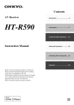
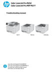
Multiroom Capability
You can use two speaker systems with this AV receiver—a surround-sound speaker system (up to 7.1 channels) in
your main listening room, a stereo speaker system in a second room, or Zone 2, as we call it. And, you can select a different audio source for each room.
Main Room: In your main listening room, you can enjoy up to 7.1-channel playback (see page 14).
You can enjoy the various listening modes such as Dolby and DTS (pages 57–65).
*While Powered Zone 2 is being used, playback is reduced to 5.1-channels (see page 83).
Zone 2: In your Zone 2 room, you can enjoy 2-channel stereo playback (see page 83).
*The listening modes cannot be used with Zone 2.
Main Room
Surround back left and right
speakers
Front left and right speakers
* While Powered Zone 2 is being
used, nothing is output by these
speakers (page 84).
Subwoofer
Center speaker
Surround left and right speakers
Zone 2 Room
Left and right
stereo speakers
7
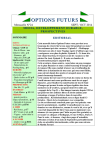
Getting to Know the AV Receiver
Front Panel
North American model
1 2 3 4 5
6
7 8 9
J
MASTER VOLUME
ON/STANDBY
TUNING
PRESET
STANDBY
ZONE 2
MULTI CH
DVD
VCR/DVR
CBL/SAT
GAME/TV
AUX
TAPE
TUNER
CD
SETUP
ENTER
RETURN
AUX INPUT
PHONES
SETUP MIC
ZONE 2
OFF
TONE
ZONE 2 LEVEL
MOVIE/TV
MUSIC
GAME
DISPLAY DIGITAL INPUT
DIMMER
VIDEO
L
AUDIO
R
MEMORY TUNING MODE
CLEAR
LISTENING MODE
AV RECEIVER
K
L
M
N
OP Q RS TUV
W
TX-SR606
X
Other models
MASTER VOLUME
ON/STANDBY
TUNING
PRESET
STANDBY
ZONE 2
PURE AUDIO
MULTI CH
DVD
VCR/DVR
CBL/SAT
GAME/TV
AUX
TAPE
TUNER
CD
SETUP
ENTER
RETURN
AUX INPUT
PHONES
SETUP MIC
ZONE 2
OFF
ZONE 2 LEVEL
TONE
MOVIE/TV
MUSIC
GAME
DISPLAY DIGITAL INPUT
VIDEO
L
AUDIO
R
RT/PTY/TP MEMORY TUNING MODE
CLEAR
LISTENING MODE
AV RECEIVER
Y
TX-SR606
T
The actual front panel has various logos printed on it. They are not shown here for clarity.
The page numbers in parentheses show where you can find the main explanation for each item.
A ON/STANDBY button (37)
Sets the AV receiver to On or Standby.
B STANDBY indicator (37)
Lights up when the AV receiver is on Standby and
flashes while a signal is being received from the
remote controller.
C ZONE 2 indicator (85)
Flashes when Zone 2 is being set. Lights up when
Zone 2 is on.
D Input selector buttons (47)
Select the following input sources: DVD,
VCR/DVR, CBL/SAT, GAME/TV, AUX, TAPE,
TUNER, CD.
The [MULTI CH] button selects the multichannel
DVD input.
8
E Remote-control sensor (13)
Receives control signals from the remote controller.
F Display
See “Display” on page 9.
G SETUP button
Opens and closes the setup menus.
H TUNING, PRESET, Arrow, and ENTER
buttons
When AM or FM is selected, the TUNING [ ]
[ ] buttons are used for radio tuning, and the PRESET [ ] [ ] buttons are used to select radio presets (see page 54). With the setup menus, they work
as arrow buttons and are used to select and set
items. The ENTER button is also used with the
setup menus.
Getting to Know the AV Receiver—Continued
For detailed information, see the pages in parentheses.
I RETURN button
S DIGITAL INPUT button (46)
Selects the previously displayed setup menu.
J MASTER VOLUME control (47)
Sets the volume of the AV receiver to Min, 1
through 79, or Max.
K PHONES jack (49)
This 1/4-inch phone jack is for connecting a standard pair of stereo headphones for private listening.
L ZONE 2 and OFF buttons (85)
The ZONE 2 button is used when setting Zone 2.
The OFF button is used to turn off Zone 2.
Selects the options for automatic audio input selection setup.
T DIMMER (RT/PTY/TP) button (48, 56)
Adjusts the display brightness.
On the European modes, this is the RT/PTY/TP button, and it’s used with RDS (Radio Data System).
See “Using RDS (European models only)” on
page 55.
U MEMORY button (54)
Used when storing or deleting radio presets.
V TUNING MODE button (52)
M ZONE 2 LEVEL button (86)
Used when adjusting the volume level of Zone 2.
N TONE, –, and + buttons (69)
Selects the Auto or Manual tuning mode for AM
and FM radio.
W SETUP MIC (38)
Used to adjust the tone (bass and treble).
O MOVIE/TV button (57)
Selects the listening modes intended for use with
movies and TV.
P MUSIC button (57)
Selects the listening modes intended for use with
music.
Q GAME button (57)
Selects the listening modes intended for use with
video games.
R DISPLAY button (49)
The automatic speaker setup microphone connects
here.
X AUX INPUT (32, 66)
Used to connect a camcorder, game console, and so
on. There are input jacks for composite video and
analog audio.
Y PURE AUDIO button (57)
On models other than the North American model,
selects the Pure Audio listening mode. The indicator
lights up when this mode is selected. Pressing this
button again selects the previous listening mode.
Displays various information about the currently
selected input source.
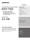
Display
1 2
5
3
6
4
7
For detailed information, see the pages in parentheses.
1 SLEEP indicator (48)
Lights up when the Sleep function has been set.
2 MUTING indicator (48)
Flashes while the AV receiver is muted.
3 Listening mode and format indicators (57)
Show the selected listening mode and audio input
signal format.
4 Tuning indicators (52)
FM STEREO (52): Lights up when tuned to a stereo FM station.
RDS (55): Lights up when tuned to a radio station
that supports RDS (Radio Data System).
AUTO (52): Lights up when Auto Tuning mode is
selected for AM or FM radio. Goes off when Manual Tuning mode is selected.
TUNED (52): Lights up when tuned to a radio station.
5 Message area
Displays various information.
6 Audio input indicators
Indicate the type of audio input that’s selected as the
audio source: MULTI CH, or HDMI.
7 Audyssey indicator
Flashes during automatic speaker setup.
9
Getting to Know the AV Receiver—Continued
Rear Panel
North American model
1 2
3
4
5
6G H
I
HDMI
ASSIGNABLE
IN 4
IN 3
(GAME/TV)
IN 2
(CBL/SAT)
(VCR/DVR)
IN 1
(DVD)
AM
SIRIUS
OUT
SURR BACK SPEAKERS
SURR SPEAKERS
Bi-AMP for FRONT SPEAKERS
DIGITAL IN
COMPONENT VIDEO
FRONT SPEAKERS
L
L
R
R
Y
1
ANTENNA
(DVD)
COAXIAL
ASSIGNABLE
DVD
CENTER SPEAKER
FM
75
V
CR/ PR
1
S
(GAME/TV)
IN 2
IN 1(DVD)
OUT
ASSIGNABLE
2
VCR/DVR
V
(CBL/SAT)
OPTICAL
GAME/TV CBL/SAT
CB/ PB
2
MONITOR
OUT
(CD)
IN
OUT
IN
S
IN
IN
OUT
IN
IN
IN
IN
OUT
IN
FRONT
SURR
ZONE 2
LINE OUT
CENTER SURR BACK
L
PRE OUT
L
L
L
R
R
SUB
WOOFER
R
R
REMOTE
CONTROL
CD
J
TAPE
GAME/TV CBL/SAT
VCR/DVR
K L MN O P
DVD
SUB
WOOFER
Q
ZONE 2 SPEAKERS
R
S
A DIGITAL IN OPTICAL 1 and 2
These optical digital audio inputs are for connecting
components with an optical digital audio output,
such as a CD player or DVD player. They’re assignable, which means you can assign each one to an
input selector to suit your setup. See “Digital Input
Setup” on page 44.
B DIGITAL IN COAXIAL 1 and 2
These coaxial digital audio inputs are for connecting components with a coaxial digital audio output,
such as a CD player or DVD player. They’re assignable, which means you can assign each one to an
input selector to suit your setup. See “Digital Input
Setup” on page 44.
an input selector to suit your setup. See “HDMI
Input Setup” on page 43.
The HDMI outputs are for connecting a TV or projector with an HDMI input.
F MONITOR OUT
The S-Video or composite video jack should be
connected to a video input on your TV or projector.
G SIRIUS antenna (on North American model)
This jack is for connecting a SIRIUS digital
antenna, sold separately (see the separate SIRIUS
instructions).
H AM and FM ANTENNA
The AM push terminals are for connecting an AM
antenna. The FM jack is for connecting an FM
antenna.
C COMPONENT VIDEO IN 1 and 2
These RCA component video inputs are for connecting components with a component video output,
such as a DVD player, DVD recorder, or DVR (digital video recorder). They’re assignable, which
means you can assign each one to an input selector
to suit your setup. See “Component Video Input
Setup” on page 44.
I FRONT L/R, CENTER, SURR L/R, and SURR
BACK L/R SPEAKERS
These terminal posts are for connecting the front
speakers, center, surround, and surround back
speakers.
The FRONT L/R and SURR BACK L/R terminal
posts can be used with front speakers and surround
back speakers, respectively, or used to bi-amp front
Speakers. See “Bi-amping Front Speakers” on
page 17.
D COMPONENT VIDEO OUT
This RCA component video output is for connecting a TV or projector with a component video input.
E HDMI IN 1–4 and OUT
HDMI (High Definition Multimedia Interface) connections carry digital audio and digital video.
The HDMI inputs are for connecting components
with an HDMI output, such as a DVD player, DVD
recorder, or DVR (digital video recorder). They’re
assignable, which means you can assign each one to
10
T
J
REMOTE CONTROL
This
(Remote Interactive) jack can be connected to the
jack on another
-capable
Onkyo component for remote and system control.
To use
, you must make an analog audio connection (RCA) between the AV receiver and the other
component, even if they are connected digitally.
Getting to Know the AV Receiver—Continued
Other models
1 2
3
4
5
6
H
I
T
U Only some
models
ZONE 2 SPEAKERS
L
HDMI
ASSIGNABLE
IN 4
IN 3
(GAME/TV)
IN 2
(CBL/SAT)
(VCR/DVR)
IN 1
(DVD)
AM
OUT
SURR BACK SPEAKERS
Bi-AMP for FRONT SPEAKERS
DIGITAL IN
SURR SPEAKERS
FRONT SPEAKERS
L
L
COMPONENT VIDEO
R
Y
1
COAXIAL
VCR/DVR
DVD
MONITOR
OUT
V
ASSIGNABLE
CENTER SPEAKER
FM
75
V
R
220-240V
R
CR/ PR
1
S
(GAME/TV)
OPTICAL
GAME/TV CBL/SAT
CB/ PB
2
(CBL/SAT)
120V
VOLTAGE
SELECTOR
ANTENNA
(DVD)
IN 2
IN 1(DVD)
OUT
ASSIGNABLE
2
(CD)
IN
OUT
IN
S
IN
IN
OUT
IN
IN
IN
IN
OUT
IN
FRONT
SURR
R
REMOTE
CONTROL
CD
J
TAPE
GAME/TV CBL/SAT
VCR/DVR
K L MN O P
DVD
ZONE 2
LINE OUT
CENTER SURR BACK
L
PRE OUT
L
L
R
R
SUB
WOOFER
SUB
WOOFER
Q
K CD IN
This analog audio input is for connecting a CD
player’s analog audio output.
L TAPE IN/OUT
These analog audio input and output jacks are for
connecting a recorder with an analog audio input
and output, such as a cassette deck, MD recorder,
etc.
M GAME/TV IN
A game console or TV output can be connected
here. There’s S-Video and composite video input
jacks for connecting the video signal.
N CBL/SAT IN
R
S
R ZONE 2 LINE OUT L/R
These analog audio outputs can be connected to the
line inputs on amplifiers in Zone 2.
S SUBWOOFER PRE OUT
This analog audio output can be connected to a
powered subwoofer.
T ZONE 2 SPEAKERS L/R
These push terminals are for connecting speakers in
Zone 2.
U VOLTAGE SELECTOR (Only some models)
This voltage selector provides compatibility with
power systems around the world (see page 3).
A cable or satellite receiver can be connected here.
There are S-Video and composite video input jacks
for connecting the video signal, and there are analog
audio input jacks for connecting the audio signal.
O VCR/DVR IN/OUT
A video component, such as a VCR or DVR, can be
connected here for recording and playback. There
are S-Video and composite video input and output
jacks for connecting the video signal, and there are
analog audio input jacks for connecting the audio
signal.
See pages 14–36 for hookup information.
P DVD IN
This input is for connecting a DVD player. There
are S-Video and composite video input jacks for
connecting the video signal.
Q DVD FRONT L/R, CENTER, SUBWOOFER,
SURR L/R, and SURR BACK L/R
This analog multichannel input is for connecting a
component with a 5.1/7.1-channel analog audio output, such as a DVD player, DVD-Audio or
SACD-capable player, or an MPEG decoder.
11
Remote Controller
Controlling the AV Receiver
C MULTI CH button (47)
Selects the multichannel DVD input.
To control the AV receiver, press the [RECEIVER]
REMOTE MODE button to select Receiver mode.
You can also use the remote controller to control
your DVD player, CD player, and other components.
See page 87 for more details.
D Arrow [ ]/[ ]/[ ]/[ ] and ENTER buttons
Used to select and adjust settings.
E SETUP button
Used to change settings.
F LISTENING MODE buttons (57)
Used to select the listening modes.
G DIMMER button (48)
Adjusts the display brightness.
84
A
H DISPLAY button (49)
Displays information about the current input source.
2
3
TUNER
Mutes or unmutes the AV receiver.
9
RECEIVER
14
I MUTING button (48)
J
*
5
5
J VOL [ ]/[ ] button (47)
Adjusts the volume of the AV receiver regardless of
the currently selected remote controller mode.
K RETURN button
Returns to the previous display when changing settings.
L AUDIO button (69)
K
L
Used to change audio settings.
When the Audio TV Out setting is set to On
(page 81), this button is disabled.
M SLEEP button (48)
Used with the Sleep function.
* SP A/B is not used in this AV receiver.
6
2
37
M
■ Controlling the tuner
To control the AV receiver’s tuner, press the [TUNER]
(or [RECEIVER]) REMOTE MODE button.
You can select AM or FM by pressing the [TUNER] button repeatedly.
1 Arrow [ ]/[ ] buttons
Used to tune into radio stations.
2 Number buttons (53)
Used to select AM and FM radio stations directly.
3 D.TUN button (53)
Selects the Direct tuning mode.
For detailed information, see the pages in parentheses.
A ON/STANDBY button (37)
Sets the AV receiver to On or Standby.
B REMOTE MODE/INPUT SELECTOR buttons
(47, 89–95)
Selects the remote controller modes and the input
sources.
12
4 DISPLAY button (53)
Displays information about the band, frequency,
preset number, and so on.
5 CH +/– button (54)
Selects radio presets.
Note:
• An Onkyo cassette recorder connected via
can
also be controlled in Receiver mode (see page 95).
Remote Controller—Continued
Installing the Batteries
1
To open the battery compartment, press
the small lever and remove the cover.
Using the Remote Controller
When using the remote controller, point it toward the AV
receiver’s remote control sensor, as shown below.
Remote control sensor
STANDBY indicator
AV receiver
30˚
2
3
Insert the two supplied batteries (AA/R6)
in accordance with the polarity diagram
inside the battery compartment.
Replace the cover and push it shut.
Notes:
• If the remote controller doesn’t work reliably, try
replacing the batteries.
• Don’t mix new and old batteries or different types of
batteries.
• If you intend not to use the remote controller for a long
time, remove the batteries to prevent damage from
leakage or corrosion.
• Expired batteries should be removed as soon as possible to prevent damage from leakage or corrosion.
30˚
Approx. 16 ft.
(5 m)
Notes:
• The remote controller may not work reliably if the AV
receiver is subjected to bright light, such as direct sunlight or inverter-type fluorescent lights. Keep this in
mind when installing.
• If another remote controller of the same type is used in
the same room, or the AV receiver is installed close to
equipment that uses infrared rays, the remote controller may not work reliably.
• Don’t put anything on top of the remote controller,
such as a book or magazine, because a button may be
pressed continuously, thereby draining the batteries.
• The remote controller may not work reliably if the AV
receiver is installed in a rack behind colored glass
doors. Keep this in mind when installing.
• The remote controller will not work if there’s an obstacle between it and the AV receiver’s remote control
sensor.
13
Connecting Your Speakers
Enjoying Home Theater
Thanks to the AV receiver’s superb capabilities, you can enjoy surround sound with a real sense of movement in your
own home—just like being in a movie theater or concert hall. You can enjoy DVDs featuring Dolby Digital or DTS.
With analog or digital TV, you can enjoy Dolby Pro Logic IIx, DTS Neo:6, or Onkyo’s original DSP listening modes.
Front left and right speakers
These output the main sound. Their role in a home theater is to provide a solid
anchor for the sound image. They should be positioned facing the listener at
about ear level, and equally spaced from the TV. Angle them inward slightly so
as to create a triangle, with the listener at the apex.
Center speaker
This speaker enhances the front left
and right speakers, making sound
movements distinct and providing a
full sound image. For movies it’s used
mainly for dialog.
Position it close to your TV (preferably
on top) facing forward at about ear
level, or at the same height as the
front left and right speakers.
Subwoofer
The subwoofer handles the bass sounds of
the LFE (Low-Frequency Effects) channel.
The volume and quality of the bass output
from your subwoofer will depend on its position, the shape of your listening room, and
your listening position. In general, a good bass
sound can be obtained by installing the subwoofer in a front corner, or at one-third the way
along the front wall, as shown.
Surround back left and right speakers
These speakers are necessary to enjoy Dolby Digital
EX, DTS-ES Matrix, DTS-ES Discrete, etc. They
enhance the realism of surround sound and improve
sound localization behind the listener. Position them
behind the listener about 2–3 feet (60–100 cm) above
ear level.
Tip: To find the best position for your subwoofer, while playing a movie or some music
with good bass, experiment by placing your
subwoofer at various positions within the room
and choose the one that provides the most
satisfying results.
Corner
position
1/3 of wall
position
14
Surround left and right speakers
These speakers are used for precise
sound positioning and to add realistic
ambience.
Position them at the sides of the listener, or slightly behind, about 2–3 feet
(60–100 cm) above ear level. Ideally
they should be equally spaced from the
listener.
Connecting Your Speakers—Continued
Speaker Configuration
Connecting a Powered Subwoofer
For 7.1-channel surround-sound playback, you need
seven speakers and a powered subwoofer.
Using a suitable cable, connect the AV receiver’s PRE
OUT: SUBWOOFER to the input on your powered subwoofer. If your subwoofer is unpowered and you’re
using an external amplifier, connect the PRE OUT: SUBWOOFER to the amp’s input.
The following table shows which channels you should
use based on the number of speakers you have.
Number of speakers:
2
3
4
5
6
7
Front left
✓
✓
✓
✓
✓
✓
HDMI
ASSIGNABLE
IN 4
✓
Front right
✓
✓
✓
Center
✓
✓
✓
Powered
subwoofer
✓
✓
IN 3
(GAME/TV)
IN 2
(CBL/SAT)
IN 1
(DVD)
AM
SIRIUS
OUT
SURR BACK SPEAKERS
SURR SPEA
L
COMPONENT VIDEO
Y
1
ANTENNA
(DVD)
COAXIAL
2
(CBL/SAT)
IN 2
IN 1(DVD)
OUT
ASSIGNABLE
2
VCR/DVR
DVD
MONITOR
OUT
FM
75
V
V
S
S
R
CR/ PR
1
(GAME/TV)
OPTICAL
GAME/TV CBL/SAT
CB/ PB
ASSIGNABLE
✓
(VCR/DVR)
Bi-AMP for FRONT SPEAKERS
DIGITAL IN
(CD)
IN
OUT
IN
IN
IN
OUT
IN
IN
IN
IN
OUT
IN
FRONT
SURR
ZONE 2
LINE OUT
CENTER SURR BACK
PRE OUT
L
L
L
L
R
R
R
SUB
WOOFER
R
LINE INPUT
Surround left
✓
✓
✓
✓
Surround right
✓
✓
✓
✓
REMOTE
CONTROL
CD
✓
Surround back right
✓
No matter how many speakers you use, a powered subwoofer is recommended for a powerful and solid bass.
To get the best from your surround-sound system, you
must set the speaker settings. You can do this automatically (see page 38) or manually (see page 72).
Using Dipole Speakers
You can use dipole speakers for the surround left and
right and surround back left and right speakers. Dipole
speakers output the same sound in two directions.
Dipole speakers typically have an arrow printed on them to
indicate how they should be positioned. The surround left
and right dipole speakers should be positioned so that their
arrows point toward your TV or screen, while the surround
back left and right dipolar speakers should be positioned
so that their arrows point toward each other, as shown.
SUB
WOOFER
Attaching the Speaker Labels
The AV receiver’s positive (+) speaker terminals are all
red. (The negative (–) speaker terminals are all black.)
Speaker
Front left
Front right
Center
Surround left
Surround right
Surround back left
Surround back right
Color
White
Red
Green
Blue
Gray
Brown
Tan
The supplied speaker labels are color-coded and you
should attach them to the positive (+) side of each
speaker cable in accordance with the above table. All you
need to do then is to match the color of each label to the
corresponding speaker terminal.
Normal speakers
Dipole speakers
1
TV/screen
DVD
SUB
WOOFER
LINE INPUT
* If you’re using only one surround back speaker, connect it to the
SURR BACK L terminals.
6
8
1. Subwoofer
2. Front left speaker
3. Center speaker
4. Front right speaker
5. Surround left speaker
1
TV/screen
4
3
2
4
5
7
VCR/DVR
PRE OUT
Surround back left
3
GAME/TV CBL/SAT
✓
Surround back*
2
TAPE
5
6
7
8
6. Surround right speaker
7. Surround back left
speaker
8. Surround back right
speaker
15
Connecting Your Speakers—Continued
Speaker Connection Precautions
Read the following before connecting your speakers:
• North American models: You can connect speakers
with an impedance of between 6 and 16 ohms. If you
use speakers with a lower impedance, and use the
amplifier at high volume levels for a long period of
time, the built-in amp protection circuit may be activated.
• Other models: You can connect speakers with an
impedance of between 4 and 16 ohms. If the impedance of any of the connected speakers is 4 ohms or
more, but less than 6 ohms, be sure to set the minimum
speaker impedance to “4 ohms” (see page 42). If you
use speakers with a lower impedance, and use the
amplifier at high volume levels for a long period of
time, the built-in amp protection circuit may be activated.
• Disconnect the power cord from the wall outlet before
making any connections.
• Read the instructions supplied with your speakers.
• Pay close attention to speaker wiring polarity. Connect
positive (+) terminals to only positive (+) terminals,
and negative (–) terminals to only negative (–) terminals. If you get them the wrong way around, the sound
will be out of phase and will sound unnatural.
• Unnecessarily long or very thin speaker cables may
affect the sound quality and should be avoided.
• Be careful not to short the
positive and negative wires.
Doing so may damage the AV
receiver.
• Don’t connect more than one
cable to each speaker terminal. Doing so may damage the
AV receiver.
• Don’t connect a speaker to several terminals.
Connecting the Speaker Cables
1
Strip about 5/8" (15
mm) of insulation from
the ends of the
speaker cables, and
twist the bare wires
tightly, as shown.
2
Unscrew the terminal.
3
Fully insert the bare wire.
4
Screw the terminal tight.
The following illustration shows which speaker should
be connected to each pair of terminals.
If you’re using only one surround back speaker, connect
it to the left (L) SURR BACK SPEAKERS terminals.
Surround
back left
speaker
Surround
back right
speaker
Front right
speaker
16
5/8" (15 mm)
Surround
left
speaker
Front left
speaker
Surround
right
speaker
Center
speaker
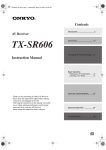
Connecting Your Speakers—Continued
Bi-amping Speaker Hookup
Bi-amping Front Speakers
The FRONT L/R and SURR BACK L/R terminal posts
can be used with front speakers and surround back
speakers respectively, or bi-amped to provide separate
tweeter and woofer feeds for front speakers, providing
improved bass and treble performance.
• When bi-amping is used, the AV receiver is able to
drive up to 5.1 speakers in the main room.
• For bi-amping, the FRONT L/R terminal posts connect to the front speakers’ tweeter terminals. And the
SURR BACK L/R terminal posts connect to the front
speakers’ woofer terminals.
• Once you’ve completed the bi-amping connections
shown below and turned on the AV receiver, you must
set the Speaker Type setting to Bi-Amp to enable biamping (see page 42).
Important:
• When making the bi-amping connections, be sure
to remove the jumper bars that link the speakers’
tweeter (high) and woofer (low) terminals.
• Bi-amping can only be used with speakers that support
bi-amping. Refer to your speaker manual.
1
Connect the AV receiver’s FRONT R positive (+)
terminal to the right speaker’s positive (+) tweeter
(high) terminal. And connect the AV receiver’s
FRONT R negative (–) terminal to the right
speaker’s negative (–) tweeter (high) terminal.
2
Connect the AV receiver’s SURR BACK R positive (+) terminal to the right speaker’s positive (+)
woofer (low) terminal. And connect the AV
receiver’s SURR BACK R negative (–) terminal to
the right speaker’s negative (–) woofer (low) terminal.
3
Connect the AV receiver’s FRONT L positive (+)
terminal to the left speaker’s positive (+) tweeter
(high) terminal. And connect the AV receiver’s
FRONT L negative (–) terminal to the left
speaker’s negative (–) tweeter (high) terminal.
4
Connect the AV receiver’s SURR BACK L positive (+) terminal to the left speaker’s positive (+)
woofer (low) terminal. And connect the AV
receiver’s SURR BACK L negative (–) terminal to
the left speaker’s negative (–) woofer (low) terminal.
HDMI
ASSIGNABLE
IN 4
IN 3
(GAME/TV)
IN 2
(CBL/SAT)
(VCR/DVR)
IN 1
(DVD)
AM
SIRIUS
OUT
SURR BACK SPEAKERS
Bi-AMP for FRONT SPEAKERS
DIGITAL IN
COMPONENT VIDEO
SURR SPEAKERS
FRONT SPEAKERS
L
L
R
R
Y
1
ANTENNA
(DVD)
COAXIAL
VCR/DVR
DVD
MONITOR
OUT
V
CENTER SPEAKER
FM
75
V
CR/ PR
1
S
(GAME/TV)
OPTICAL
GAME/TV CBL/SAT
CB/ PB
2
(CBL/SAT)
ASSIGNABLE
IN 2
IN 1(DVD)
OUT
ASSIGNABLE
2
(CD)
IN
OUT
IN
S
IN
IN
OUT
IN
IN
IN
IN
OUT
IN
FRONT
SURR
ZONE 2
LINE OUT
CENTER SURR BACK
L
PRE OUT
L
L
L
R
R
SUB
WOOFER
R
R
REMOTE
CONTROL
CD
TAPE
GAME/TV CBL/SAT
VCR/DVR
DVD
SUB
WOOFER
ZONE 2 SPEAKERS
SURR BACK SPEAKERS
Bi-AMP for FRONT SPEAKERS
FRONT SPEAKERS
L
L
Left speaker
Woofer (low)
Tweeter (high)
R
R
Right speaker
Woofer (low)
Tweeter (high)
17
Connecting Antennas
This section explains how to connect the supplied indoor
FM antenna and AM loop antenna, and how to connect
commercially available outdoor FM and AM antennas.
The AV receiver won’t pick up any radio signals without
any antenna connected, so you must connect the antenna
to use the tuner.
AM antenna push terminals
Connecting the AM Loop Antenna
The supplied indoor AM loop antenna is for indoor use
only.
1
Assemble the AM loop antenna, inserting
the tabs into the base, as shown.
2
Connect both wires of the AM loop
antenna to the AM push terminals, as
shown.
(The antenna’s wires are not polarity sensitive, so
they can be connected either way around).
AM
ANTENNA
FM
75
FM antenna jack
Connecting the Indoor FM Antenna
The supplied indoor FM antenna is for indoor use only.
1
Attach the FM antenna, as shown.
■ American Model
FM
75
Insert the plug fully
into the jack.
Make sure that the wires are attached securely and
that the push terminals are gripping the bare
wires, not the insulation.
Push
Insert wire
Release
■ Other Models
AM
FM
75
ANTENNA
Insert the plug fully
into the jack.
Once your AV receiver is ready for use, you’ll
need to tune into an FM radio station and adjust
the position of the FM antenna to achieve the best
possible reception.
2
Use thumbtacks or something similar to
fix the FM antenna into position.
Once your AV receiver is ready for use, you’ll
need to tune into an AM radio station and adjust
the position of the AM antenna to achieve the best
possible reception.
Keep the antenna as far away as possible from
your AV receiver, TV, speaker cables, and power
cords.
If you cannot achieve good reception with the supplied
indoor AM loop antenna, try using it with a commercially available outdoor AM antenna (see page 19).
Thumbtacks, etc.
Caution: Be careful that you don’t injure yourself
when using thumbtacks.
If you cannot achieve good reception with the supplied
indoor FM antenna, try a commercially available outdoor FM antenna instead (see page 19).
18
Connecting Antennas—Continued
Connecting an Outdoor FM Antenna
Connecting an Outdoor AM Antenna
If you cannot achieve good reception with the supplied
indoor FM antenna, try a commercially available outdoor FM antenna instead.
If good reception cannot be achieved using the supplied
AM loop antenna, an outdoor AM antenna can be used in
addition to the loop antenna, as shown.
Outdoor antenna
Insulated antenna cable
FM
75
AM loop antenna
AM
Notes:
• Outdoor FM antennas work best outside, but usable
results can sometimes be obtained when installed in an
attic or loft.
• For best results, install the outdoor FM antenna well
away from tall buildings, preferably with a clear line
of sight to your local FM transmitter.
• Outdoor antenna should be located away from possible noise sources, such as neon signs, busy roads, etc.
• For safety reasons, outdoor antenna should be situated
well away from power lines and other high-voltage
equipment.
• Outdoor antenna must be grounded in accordance
with local regulations to prevent electrical shock hazards.
ANTENNA
Outdoor AM antennas work best when installed horizontally outside, but good results can sometimes be obtained
indoors by mounting horizontally above a window. Note
that the AM loop antenna should be left connected.
Outdoor antenna must be grounded in accordance with
local regulations to prevent electrical shock hazards.
■ Using a TV/FM Antenna Splitter
It’s best not to use the same antenna for both FM and TV
reception, as this can cause interference problems. If circumstances demand it, use a TV/FM antenna splitter, as
shown.
TV/FM antenna splitter
To AV receiver
To TV (or VCR)
19
Connecting Your Components
AV Connection Color Coding
About AV Connections
RCA-type AV connections are usually color coded: red,
white, and yellow. Use red plugs to connect rightchannel audio inputs and outputs (typically labeled “R”).
Use white plugs to connect left-channel audio inputs and
outputs (typically labeled “L”). And use yellow plugs to
connect composite video inputs and outputs.
• Before making any AV connections, read the manuals
supplied with your other AV components.
• Don’t connect the power cord until you’ve completed
and double-checked all AV connections.
Optical Digital Jacks
Left (white)
The AV receiver’s optical digital jacks have shutter-type
covers that open when an optical plug is inserted and
close when it’s removed. Push plugs in all the way.
Analog audio
Right (red)
(Yellow)
Caution: To prevent shutter damage, hold the optical
plug straight when inserting and removing.
Left (white)
Right (red)
Composite video
• Push plugs in all the way to make
good connections (loose connections can cause noise or malfunctions).
• To prevent interference, keep
audio and video cables away from
power cords and speaker cables.
(Yellow)
Right!
Wrong!
AV Cables and Jacks
Video
Cable
Jack
Description
HDMI connections can carry uncompressed standard- or high-definition digital video and audio and
offer the best picture and sound quality.
HDMI
HDMI
Component
video cable
Y
Y
PB
PB
PR
PR
Component video separates the luminance (Y) and
color difference signals (PR, PB), providing the best
picture quality. (Some TV manufacturers label their
component video jacks slightly differently.)
Y
CB/PB
CR/PR
S-Video cable
S
S-Video separates the luminance and color signals
and provides better picture quality than composite
video.
Composite
video cable
V
Composite video is commonly used on TVs, VCRs,
and other video equipment.
Audio
Optical digital
audio cable
OPTICAL
Coaxial digital
audio cable
COAXIAL
R
FRONT
Multichannel
analog audio
cable (RCA)
CENTER
SUBWOOFER
SURR
SURR BACK
MULTI CH
Note: The AV receiver does not support SCART connections.
20
This offers the best sound quality and allows you to
enjoy Dolby Digital and DTS. The audio quality is
the same as for optical.
This cable carries analog audio. It’s the most
common connection format for analog audio and
can be found on virtually all AV components.
L
Analog audio
cable (RCA)
This offers the best sound quality and allows you to
enjoy Dolby Digital and DTS. The audio quality is
the same as for coaxial.
This cable carries multichannel analog audio and is
typically used to connect DVD players with a 7.1channel analog audio output. Several standard
analog audio cables can be used instead of a multichannel cable.
Connecting Your Components—Continued
Connecting Audio and Video Signals to the AV Receiver
By connecting both the audio and video outputs of your DVD player and other AV components to the AV receiver, you
can switch the audio and video signals simultaneously simply by changing the input source on the AV receiver.
: Signal Flow
Video
Video
Audio
Audio
TV, projector,
etc.
DVD player, etc.
Speakers (see page 16 for hookup details)
Which Connections Should I Use?
The AV receiver supports several connection formats for compatibility with a wide range of AV equipment. The format
you choose will depend on the formats supported by your other components. Use the following sections as a guide.
For video components, you must make an audio connection and a video connection.
Audio Connection Formats
Audio equipment can be connected to the AV
receiver by using any of the following audio
connection formats: analog, optical, coaxial,
analog multichannel, or HDMI.
When you connect audio equipment to an
HDMI, OPTICAL, or COAXIAL input, you
must assign that input to an input selector (see
pages 44).
When choosing a connection format, bear in
mind that the AV receiver does not convert digital input signals for analog line outputs and
vice versa. For example, audio signals connected to an optical or coaxial digital input are
not output by the analog TAPE OUT.
Audio Signal Flow Chart
DVD player, etc.
HDMI Multichannel
Optical
Coaxial
Analog
AV receiver
HDMI
Analog
MD recorder, etc.
If signals are present at more than one input, the inputs will be selected automatically in the following order of priority:
HDMI, digital, analog (including multichannel). You can specify which audio inputs the AV receiver checks for the
presence of a signal in the “Automatic Audio Input Selection Setup” on page 46.
21
Connecting Your Components—Continued
Video Connection Formats
Video equipment can be connected to the AV
receiver by using any one of the following
video connection formats: composite video,
S-Video, component video, or HDMI, the latter offering the best picture quality.
Video input signals flow through the AV
receiver as shown, with composite video, SVideo, and component video sources all being
upconverted for the HDMI output.
Video Signal Flow Chart
DVD player, etc.
Composite
If signals are present at more than one input,
the inputs will be selected automatically in the
following order of priority: HDMI, component
video, S-Video, composite video. However, for
component video only, regardless of whether a
component video signal is actually present, if a
component video input is assigned to the input
selector, that component video input will be
selected. And if no component video input is
assigned to the input selector, this will be interpreted as no component video signal being
present.
In the Signal Selection Example shown on the
right, video signals are present at both the
S-Video and composite video inputs, however,
the S-Video signal is automatically selected as
the source and video is output by the S-Video
and HDMI outputs.
Component
HDMI
IN
AV receiver
MONITOR OUT
The composite video, S-Video, and component
video outputs pass through their respective
input signals as they are.
When you connect audio equipment to an
HDMI or COMPONENT input, you must
assign that input to an input selector (see pages
43 and 44).
S-Video
Composite
S-Video
Component
HDMI
S-Video
Component
HDMI
TV, projector, etc.
Signal Selection Example
DVD player, etc.
Composite
IN
AV receiver
MONITOR OUT
Composite
S-Video
Component
HDMI
TV, projector, etc.
The onscreen setup menus appear only on a TV that is connected to the HDMI OUT. If your TV is connected to the
composite video or S-Video MONITOR OUT, or the COMPONENT VIDEO OUT, use the TX-SR606’s display when
changing settings.
22
Connecting Your Components—Continued
Connecting a TV or Projector
Step 1: Video Connection
Choose a video connection that matches your TV ( A , B , or C ), and then make the connection.
Step 2: Audio Connection
Choose an audio connection that matches your TV ( a , b , or c ), and then make the connection.
The onscreen setup menus appear only on a TV that is connected to the HDMI OUT. If your TV is connected to the
composite video or S-Video MONITOR OUT, or the COMPONENT VIDEO OUT, use the TX-SR606’s display when
changing settings.
• With connection a , you can listen to and record audio from your TV or listen in Zone 2.
• To enjoy Dolby Digital and DTS, use connection b or c . (To record or listen in Zone 2 as well, use a and b ,
or a and c .)
Connection
AV receiver
Signal flow
TV
A
COMPONENT VIDEO OUT
Best
B
S-Video input
Better
C
MONITOR OUT V
Composite video input
Standard
a
GAME/TV IN L/R
b
DIGITAL IN COAXIAL 2
c
DIGITAL IN OPTICAL 1
⇒
⇒
⇒
⇐
⇐
⇐
Component video input
MONITOR OUT S
DIGITAL IN
Picture quality
Analog audio L/R output
Digital coaxial output
Digital optical output
L
COMPONENT VIDEO
Y
1
ANTENNA
(DVD)
b
COAXIAL
2
(CBL/SAT)
ASSIGNABLE
1
OPTICAL
IN 2
IN 1(DVD)
OUT
ASSIGNABLE
2
VCR/DVR
DVD
C
MONITOR
OUT
FM
75
V
V
S
S
R
CR/ PR
(GAME/TV)
c
GAME/TV CBL/SAT
CB/ PB
(CD)
IN
OUT
IN
IN
IN
OUT
IN
IN
IN
IN
OUT
IN
FRONT
B
SURR
CENTER SURR BACK
L
R
A
REMOTE
CONTROL
CD
TAPE
GAME/TV CBL/SAT
VCR/DVR
L
COAXIAL
OUT
Connect one or the other
Connection c must be assigned
(see page 44)
Hint!
OPTICAL
OUT
Y
PB
PR
COMPONENT VIDEO IN
DVD
SUB
WOOFER
ZONE 2
LINE OUT
PR
L
L
R
R
W
a
R
AUDIO
OUT
S VIDEO
IN
VIDEO
IN
TV, projector,
etc.
If your TV has no audio outputs, connect an audio output from your VCR or cable or satellite
receiver to the AV receiver and use its tuner to listen to TV programs through the AV receiver (see
pages 26 and 28).
23
Connecting Your Components—Continued
Connecting a DVD player
Step 1: Video Connection
Choose a video connection that matches your DVD player ( A , B , or C ), and then make the connection.
You must connect the AV receiver to your TV with the same type of connection.
Step 2: Audio Connection
Choose an audio connection that matches your DVD player ( a , b , or c ), and then make the connection.
• With connection a , you can listen to and record audio from a DVD or listen in Zone 2.
• To enjoy Dolby Digital and DTS, use connection b or c . (To record or listen in Zone 2 as well, use a and b ,
or a and c .)
• If your DVD player has main left and right outputs and multichannel left and right outputs, be sure to use the
main left and right outputs for connection a .
Connection
AV receiver
Signal flow
DVD player
Picture quality
A
COMPONENT VIDEO IN 1
Best
B
S-Video output
Better
C
DVD IN V
Composite video output
Standard
a
DVD IN FRONT L/R
b
DIGITAL IN COAXIAL 1
c
DIGITAL IN OPTICAL 1
⇐
⇐
⇐
⇐
⇐
⇐
Component video output
DVD IN S
Analog audio L/R output
Digital coaxial output
Digital optical output
ASSIGNABLE
IN 4
IN 3
(GAME/TV)
IN 2
(CBL/SAT)
(VCR/DVR)
IN 1
(DVD)
AM
SIRIUS
OUT
SURR BACK SPEAKERS
Bi-AMP for FRONT SPEAKERS
b
DIGITAL IN
L
COMPONENT VIDEO
Y
1
ANTENNA
(DVD)
COAXIAL
2
(CBL/SAT)
c
ASSIGNABLE
IN 2
IN 1(DVD)
(CD)
IN
A
DVD
MONITOR
OUT
V
S
S
OUT
OUT
IN
IN
IN
OUT
IN
IN
IN
IN
OUT
IN
FRONT
L
R
R
TAPE
GAME/TV CBL/SAT
L
Connect one or the other
Connection c must be
assigned (see page 44)
ZONE 2
LINE OUT
CENTER SURR BACK
L
CD
OPTICAL
OUT
C
R
B
SURR
REMOTE
CONTROL
COAXIAL
OUT
FM
75
V
ASSIGNABLE
2
VCR/DVR
CR/ PR
1
(GAME/TV)
OPTICAL
GAME/TV CBL/SAT
CB/ PB
Y
PB
PR
COMPONENT VIDEO OUT
VCR/DVR
DVD
PRE OUT
L
a
SUB
WOOFER
R
SUB
WOOFER
R
AUDIO
OUT
S VIDEO
OUT
VIDEO
OUT
DVD player
To connect a DVD player or DVD-Audio/SACD-capable player with a
multichannel analog audio output, see page 25.
24
Connecting Your Components—Continued
Hooking Up the Multichannel Input
If your DVD player supports multichannel audio formats such as DVD-Audio and SACD, and it has a multichannel
analog audio output, you can connect it to the AV receiver’s multichannel input.
Use a multichannel analog audio cable, or several normal audio cables, to connect the AV receiver’s DVD IN FRONT
L/R, CENTER, SURR L/R, SURR BACK L/R, and SUBWOOFER jacks to the 7.1-channel analog audio output on your
DVD player. If your DVD player has a 5.1-channel analog audio output, don’t connect anything to the AV receiver’s
SURR BACK L/R jacks.
To select the multichannel input, see “Basic AV Receiver Operation” on page 47. To adjust the subwoofer sensitivity for
the multichannel input, see “Hardware Setup” on page 79.
HDMI
ASSIGNABLE
IN 4
IN 3
(GAME/TV)
IN 2
(CBL/SAT)
(VCR/DVR)
IN 1
(DVD)
AM
SIRIUS
OUT
SURR BACK SPEAKERS
SURR SPEAKERS
Bi-AMP for FRONT SPEAKERS
DIGITAL IN
COMPONENT VIDEO
FRONT SPEAKERS
L
L
R
R
Y
1
ANTENNA
(DVD)
COAXIAL
ASSIGNABLE
DVD
CENTER SPEAKER
FM
75
V
CR/ PR
1
S
(GAME/TV)
IN 2
IN 1(DVD)
OUT
ASSIGNABLE
2
VCR/DVR
V
(CBL/SAT)
OPTICAL
GAME/TV CBL/SAT
CB/ PB
2
MONITOR
OUT
(CD)
IN
OUT
IN
S
IN
IN
OUT
IN
IN
IN
IN
OUT
IN
FRONT
SURR
ZONE 2
LINE OUT
CENTER SURR BACK
L
PRE OUT
L
L
L
R
R
SUB
WOOFER
R
R
REMOTE
CONTROL
CD
TAPE
GAME/TV CBL/SAT
VCR/DVR
DVD
SUB
WOOFER
ZONE 2 SPEAKERS
7.1 ch
5.1 ch
FRONT
SURR
CENTER
SURR BACK
L
L
R
R
DVD
L
R
FRONT
L
SUB
WOOFER
R
SURROUND
L
CENTER
SUB
WOOFER
R
SURR
BACK
DVD player
25
Connecting Your Components—Continued
Connecting a VCR or DVR for Playback
With this hookup, you can use the tuner in your VCR or DVR to listen to your favorite TV programs
via the AV receiver, which is useful if your TV has no audio outputs.
Hint!
Step 1: Video Connection
Choose a video connection that matches your VCR or DVR ( A , B , or C ), and then make the connection. You must
connect the AV receiver to your TV with the same type of connection.
Step 2: Audio Connection
Choose an audio connection that matches your VCR or DVR ( a , b , or c ), and then make the connection.
• With connection a , you can listen to the VCR or DVR in Zone 2.
• To enjoy Dolby Digital and DTS, use connection b or c . (To listen in Zone 2 as well, use a and b , or a and
c .)
Connection
AV receiver
Signal flow
VCR or DVR
Picture quality
A
COMPONENT VIDEO IN 2
Component video output
Best
B
VCR/DVR IN S
⇐
⇐
⇐
⇐
⇐
⇐
S-Video output
Better
Composite video output
Standard
C
VCR/DVR IN V
a
VCR/DVR IN L/R
b
DIGITAL IN COAXIAL 2
c
DIGITAL IN OPTICAL 1
IN 4
IN 3
(GAME/TV)
IN 2
(CBL/SAT)
(VCR/DVR)
Analog audio L/R output
Digital coaxial output
Digital optical output
IN 1
(DVD)
SIRIUS
OUT
SURR BACK SPEAKERS
Bi-AMP for FRONT SPEAKERS
DIGITAL IN
L
COMPONENT VIDEO
Y
1
ANTENNA
(DVD)
b
COAXIAL
VCR/DVR
DVD
MONITOR
OUT
V
(CBL/SAT)
ASSIGNABLE
1
S
OPTICAL
IN 2
IN 1(DVD)
(CD)
IN
R
OUT
IN
IN
IN
OUT
IN
IN
IN
IN
OUT
IN
FRONT
B
SURR
R
REMOTE
CONTROL
CD
TAPE
GAME/TV CBL/SAT
L
COAXIAL
OUT
OPTICAL
OUT
Y
PB
PR
COMPONENT VIDEO OUT
VCR/DVR
R
AUDIO
OUT
S VIDEO
OUT
Connect one or the other
Connection b must be
assigned (see page 44)
VCR or DVR
26
DVD
VIDEO
OUT
ZONE 2
LINE OUT
CENTER SURR BACK
L
A
C
S
OUT
ASSIGNABLE
2
FM
75
V
CR/ PR
(GAME/TV)
c
GAME/TV CBL/SAT
CB/ PB
2
SUB
WOOFER
a
PRE OU
L
L
R
R
SUB
WOOFE
Connecting Your Components—Continued
Connecting a VCR or DVR for Recording
Step 1: Video Connection
Choose a video connection that matches your VCR or DVR ( A or B ), and then make the connection. The video
source to be recorded must be connected to the AV receiver via the same type of connection.
Step 2: Audio Connection
Make the audio connection a .
Connection
AV receiver
Signal flow
VCR or DVD recorder
Picture quality
A
VCR/DVR OUT S
S-Video input
Better
B
VCR/DVR OUT V
Composite video input
Standard
a
VCR/DVR OUT L/R
⇒
⇒
⇒
Audio L/R input
ASSIGNABLE
IN 4
IN 3
(GAME/TV)
IN 2
(CBL/SAT)
(VCR/DVR)
IN 1
(DVD)
AM
SIRIUS
OUT
SURR BACK SPEAKERS
Bi-AMP for FRONT SPEAKERS
DIGITAL IN
SURR
L
COMPONENT VIDEO
Y
1
ANTENNA
(DVD)
COAXIAL
GAME/TV CBL/SAT
CB/ PB
2
(CBL/SAT)
ASSIGNABLE
MONITOR
OUT
B
FM
75
V
V
IN 2
IN 1(DVD)
S
S
OUT
ASSIGNABLE
2
DVD
R
CR/ PR
1
(GAME/TV)
OPTICAL
VCR/DVR
(CD)
IN
IN
OUT
IN
IN
OUT
IN
IN
IN
IN
OUT
IN
FRONT
A
SURR
L
R
REMOTE
CONTROL
CD
TAPE
GAME/TV CBL/SAT
L
VCR/DVR
DVD
ZONE 2
LINE OUT
CENTER SURR BACK
SUB
WOOFER
PRE OUT
L
L
R
R
SUB
WOOFER
a
R
AUDIO
IN
S VIDEO
IN
VIDEO
IN
VCR or DVR
Notes:
• The AV receiver must be turned on for recording. Recording is not possible while it’s on Standby.
• If you want to record directly from your TV or another video source without going through the AV receiver, connect
the audio and video outputs from your TV or other video component directly to the recording VCR/DVR’s audio and
video inputs. See the manuals supplied with your TV or VCR/DVR for details.
• Video signals connected to composite video inputs can only be recorded via the VCR/DVR OUT V jack. So if your
source TV or VCR is connected to a composite video input, the recording VCR/DVR must be connected to the
VCR/DVR OUT V jack. Likewise, video signals connected to S-Video inputs can only be recorded via the VCR/DVR
OUT S jack. So if your source TV or VCR is connected to an S-Video input, the recording VCR/DVR must be
connected to the VCR/DVR OUT S jack.
27
Connecting Your Components—Continued
Connecting a Satellite, Cable, Terrestrial Set-top box, or Other Video Source
With this hookup, you can use your satellite or cable receiver to listen to your favorite TV programs
via the AV receiver, which is useful if your TV has no audio outputs.
Hint!
Step 1: Video Connection
Choose a video connection that matches the video source ( A , B , or C ), and then make the connection.
You must connect the AV receiver to your TV with the same type of connection.
Step 2: Audio Connection
Choose an audio connection that matches the video source ( a , b , or c ), and then make the connection.
• With connection a , you can listen to and record audio from the video source or listen in Zone 2.
• To enjoy Dolby Digital and DTS, use connection b or c . (To record or listen in Zone 2 as well, use a and b ,
or a and c .)
Connection
AV receiver
Signal flow
Video source
Picture quality
A
COMPONENT VIDEO IN 2
Best
B
S-Video output
Better
C
CBL/SAT IN V
Composite video output
Standard
a
CBL/SAT IN L/R
b
DIGITAL IN COAXIAL 2
c
DIGITAL IN OPTICAL 1
⇐
⇐
⇐
⇐
⇐
⇐
Component video output
CBL/SAT IN S
Analog audio L/R output
Digital coaxial output
Digital optical output
HDMI
ASSIGNABLE
IN 4
IN 3
(GAME/TV)
IN 2
(CBL/SAT)
IN 1
(VCR/DVR)
(DVD)
AM
SIRIUS
OUT
SURR BACK SPEAKERS
Bi-AMP for FRONT SPEAKERS
DIGITAL IN
L
COMPONENT VIDEO
Y
1
ANTENNA
(DVD)
b
COAXIAL
1
C
MONITOR
OUT
FM
75
V
S
IN 2
IN 1(DVD)
OUT
ASSIGNABLE
2
DVD
R
CR/ PR
(GAME/TV)
c
VCR/DVR
V
ASSIGNABLE
OPTICAL
GAME/TV CBL/SAT
CB/ PB
2
(CBL/SAT)
(CD)
IN
OUT
IN
S
IN
IN
OUT
IN
IN
IN
IN
OUT
IN
FRONT
B
SURR
CENTER SURR BACK
L
A
R
REMOTE
CONTROL
CD
TAPE
GAME/TV CBL/SAT
L
COAXIAL
OUT
Connect one or the other
Connection c must be
assigned (see page 44)
28
OPTICAL
OUT
Y
PB
PR
COMPONENT VIDEO OUT
VCR/DVR
DVD
R
AUDIO
OUT
S VIDEO
OUT
VIDEO
OUT
Satellite, cable, set-top box, etc.
SUB
WOOFER
a
ZONE 2
LINE OUT
PRE OUT
L
L
R
R
SUB
WOOFER
Connecting Your Components—Continued
Connecting a Game Console
Step 1: Video Connection
Choose a video connection that matches your game console ( A , B , or C ), and then make the connection.
If you use connection A , you must connect the AV receiver to your TV with the same type of connection.
Step 2: Audio Connection
Choose an audio connection that matches your DVD player ( a , b , or c ), and then make the connection.
• With connection a , you can listen to and record audio from your game console or listen in Zone 2.
• To enjoy Dolby Digital and DTS, use connection b . (To record or listen in Zone 2 as well, use a and b .)
Connection
AV receiver
Signal flow
Game console
Picture quality
A
COMPONENT VIDEO IN 2
Component video output
Best
B
GAME/TV IN S
S-Video output
Better
C
GAME/TV IN V
⇐
⇐
⇐
⇐
⇐
Composite video output
Standard
a
GAME/TV IN L/R
b
DIGITAL OPTICAL IN 1
Analog audio L/R output
Digital optical output
HDMI
ASSIGNABLE
IN 4
IN 3
(GAME/TV)
IN 2
(CBL/SAT)
IN 1
(VCR/DVR)
(DVD)
AM
SIRIUS
OUT
SURR BACK SPEAKERS
Bi-AMP for FRONT SPEAKERS
DIGITAL IN
L
COMPONENT VIDEO
Y
1
ANTENNA
(DVD)
COAXIAL
ASSIGNABLE
1
C
MONITOR
OUT
FM
75
V
S
IN 2
IN 1(DVD)
OUT
ASSIGNABLE
2
DVD
R
CR/ PR
(GAME/TV)
b
VCR/DVR
V
(CBL/SAT)
OPTICAL
GAME/TV CBL/SAT
CB/ PB
2
(CD)
IN
OUT
IN
S
IN
IN
OUT
IN
IN
IN
IN
OUT
IN
FRONT
B
SURR
CENTER SURR BACK
L
A
R
REMOTE
CONTROL
CD
TAPE
GAME/TV CBL/SAT
L
OPTICAL
OUT
Y
PB
PR
COMPONENT VIDEO OUT
VCR/DVR
DVD
SUB
WOOFER
ZONE 2
LINE OUT
PRE O
L
L
R
R
SUB
WOOF
a
R
AUDIO
OUT
S VIDEO
OUT
VIDEO
OUT
Game Console
29
Connecting Your Components—Continued
Connecting Components with HDMI
About HDMI
Designed to meet the increased demands of digital TV, HDMI (High Definition Multimedia Interface) is a new digital
interface standard for connecting TVs, projectors, DVD players, set-top boxes, and other video components. Until now,
several separate video and audio cables have been required to connect AV components. With HDMI, a single cable can
carry control signals, digital video, and up to eight channels of digital audio (2-channel PCM, multichannel digital
audio, or multichannel PCM).
The HDMI video stream (i.e., video signal) is compatible with DVI (Digital Visual Interface),*1 so TVs and displays
with a DVI input can be connected by using an HDMI-to-DVI adapter cable. (This may not work with some TVs and
displays, resulting in no picture.)
The AV receiver uses HDCP (High-bandwidth Digital Content Protection), so only HDCP-compatible components will
display a picture.
The AV receiver’s HDMI interface is based on the following standard:
Repeater System, Deep Color, Lip Sync, DTS-HD Master Audio, DTS-HD High Resolution Audio, Dolby
TrueHD, Dolby Digital Plus, SA-CD and Multichannel PCM
Supported Audio Formats
• 2-channel linear PCM (16/20/24 bit/32–192kHz)
• Multichannel linear PCM (7.1 ch, 32–192kHz)
• Bitstream (Dolby Digital, Dolby Digital Plus, DTS, DTS-HD Master Audio, DTS-HD High Resolution Audio, Dolby
TrueHD, DSD)
Your DVD player must be able to output these formats from its HDMI OUT.
About Copyright Protection
The AV receiver supports HDCP (High-bandwidth Digital Content Protection),*2 a copy-protection system for digital
video signals. Other devices connected to the AV receiver via HDMI must also support HDCP.
Use a commercially available HDMI cable (supplied with some components) to connect the AV receiver’s HDMI OUT
to the HDMI input on your TV or projector.
*1 DVI (Digital Visual Interface): The digital display interface standard set by the DDWG*3 in 1999.
*2 HDCP (High-bandwidth Digital Content Protection): The video encryption technology developed by Intel for HDMI/DVI. It’s designed to
protect video content and requires a HDCP-compatible device to display the encrypted video.
*3 DDWG (Digital Display Working Group): Led by Intel, Compaq, Fujitsu, Hewlett Packard, IBM, NEC, and Silicon Image, this open
industry group’s objective is to address the industry’s requirements for a digital connectivity specification for high-performance PCs and
digital displays.
30
Connecting Your Components—Continued
Making HDMI Connections
Step 1: Use HDMI cables to connect the AV receiver’s HDMI jacks to your HDMI-compatible DVD player, TV,
projector, and so on.
Step 2: Assign each HDMI IN to an input selector in the HDMI Input Setup (see page 43).
■ Video Signals
Digital video signals received by the HDMI IN jacks are normally output by the HDMI OUT for display on your TV.
Composite video, S-Video, and component video sources can be upconverted for the HDMI output. See “Video Connection Formats” on page 22 for more information.
■ Audio Signals
Digital audio signals received by the HDMI IN jacks are output by the speakers and headphones connected to the AV
receiver. Normally, they are not output by the HDMI OUT, unless the Audio TV Out setting is set to On (see page 81).
Hint!
To listen to audio received by the HDMI IN jacks through your TV’s speakers, set the Audio TV Out
setting to On (see page 81), and set your DVD player’s HDMI audio output setting to PCM.
HDMI
IN
HDMI
OUT
TV
DVD player
IN 1
OUT
(DVD)
HDMI
ASSIGNABLE
IN 4
IN 3
(GAME/TV)
IN 2
(CBL/SAT)
(VCR/DVR)
IN 1
(DVD)
AM
OUT
SURR BACK SPEAKERS
Bi-AMP for FRONT SPEAKERS
DIGITAL IN
COMPONENT VIDEO
SURR SPEAKERS
FRONT SPEAKERS
L
L
R
R
Y
1
ANTENNA
(DVD)
COAXIAL
CB/ PB
2
DVD
MONITOR
OUT
CENTER SPEAKER
FM
75
V
CR/ PR
1
S
(GAME/TV)
IN 2
IN 1(DVD)
OUT
ASSIGNABLE
2
VCR/DVR
V
(CBL/SAT)
ASSIGNABLE
OPTICAL
GAME/TV CBL/SAT
(CD)
IN
OUT
IN
S
IN
IN
OUT
IN
IN
IN
IN
OUT
IN
FRONT
SURR
ZONE 2
LINE OUT
CENTER SURR BACK
PRE OUT
L
L
L
R
R
R
REMOTE
CONTROL
CD
TAPE
GAME/TV CBL/SAT
VCR/DVR
DVD
SUB
WOOFER
SUB
WOOFER
Notes:
• The HDMI video stream is compatible with DVI (Digital Visual Interface), so TVs and displays with a DVI input can
be connected by using an HDMI-to-DVI adapter cable. (Note that DVI connections only carry video, so you’ll need
to make a separate connection for audio.) However, reliable operation with such an adapter is not guaranteed. In
addition, video signals from a PC are not supported.
• When listening to an HDMI component through the AV receiver, set the HDMI component so that its video can be
seen on the TV screen (on the TV, select the input of the HDMI component connected to the AV receiver). If the TV
power is off or the TV is set to another input source, this may result in no sound from the AV receiver or the sound
may be cut off.
• The HDMI audio signal (sampling rate, bit length, etc.) may be restricted by the connected source component. If the
picture is poor or there’s no sound from a component connected via HDMI, check its setup. Refer to the connected
component’s instruction manual for details.
31
Connecting Your Components—Continued
Connecting a Camcorder or Other Device
Step 1: Make the video connection A .
Step 2: Make the audio connection a .
MASTER VOLUME
TUNING
a
PRESET
AUX INPUT
L AUDIO R
SETUP
ENTER
RETURN
L AUDIO R
OUT
AUX INPUT
SETUP MIC
VIDEO
L
AUDIO
A
R
TUNING MODE
AV RECEIVER
TX-SR606
AUX INPUT
VIDEO
VIDEO OUT
Camcorder, etc.
Connection
32
AV receiver
A
AUX INPUT VIDEO
a
AUX INPUT L-AUDIO-R
Signal flow
Camcorder or console
⇐
⇐
Analog audio L/R output
Composite video output
Connecting Your Components—Continued
Connecting a CD Player or Turntable
■ CD Player or Turntable (MM) with Built-in Phono Preamp
Step 1:
Choose a connection that matches your CD player ( a , b , or c ). Use connection a for a turntable with a built-in
phono preamp.
HDMI
ASSIGNABLE
b
IN 4
COAXIAL
DIGITAL IN
2
IN 3
(GAME/TV)
IN 2
(CBL/SAT)
IN
LANTENNA
(DVD)
COAXIAL
MONITOR
OUT
DVD
R
S
OPTICAL
IN 2
ASSIGNABLE
2
(CD)
IN
IN
L
OUT
R
S
OUT
IN 1(DVD)
L
FM
75
V
CR/ PR
1
(GAME/TV)
(CD)
VCR/DVR
V
ASSIGNABLE
OPTICAL
2
GAME/TV CBL/SAT
CB/ PB
2
(CBL/SAT)
c
AM
SIRIUS
OUT
(DVD)
Y
1
(CBL/SAT)
Connect one
or the other
Connection c
must be
assigned (see
page 44)
IN 1
(VCR/DVR)
COMPONENT VIDEO
IN
IN
IN
OUT
IN
IN
IN
IN
OUT
IN
FRONT
AUDIO
OUTPUT
CD
SURR
CENTER SURR BACK
L
a
R
R
L
REMOTE
CONTROL
CD
TAPE
GAME/TV CBL/SAT
VCR/DVR
DVD
SUB
WOOFER
R
CD
COAXIAL
OUT
a
L
OPTICAL
OUT
R
AUDIO
OUT
Turntable (MM) with
built-in phono preamp
CD player
• With connection a , you can listen to and record audio from the CD player or listen in Zone 2.
• To connect the CD player digitally, use connection b or c . (To record or listen in Zone 2 as well, use a and
b , or a and c .)
Connection
AV receiver
Signal flow
a
CD IN L/R
b
DIGITAL IN COAXIAL 2
c
DIGITAL IN OPTICAL 2
■ Turntable (MM) with no Phono Preamp Built-in
A phono preamp is necessary to connect a turntable that
doesn’t have a phono preamp built-in.
CD or turntable
⇐
⇐
⇐
Analog audio L/R output
Digital coaxial output
Digital optical output
■ Turntable with an MC (Moving Coil) Cartridge
An MC head amp and phono preamp are necessary to
connect a turntable with an MC (Moving Coil) cartridge.
HDMI
HDMI
ASSIGNABLE
IN 4
DIGITAL IN
IN 3
(GAME/TV)
IN 2
(CBL/SAT)
IN 1
(VCR/DVR)
(DVD)
AM
SIRIUS
OUT
ASSIGNABLE
IN 4
COMPONENT VIDEO
DIGITAL IN
Y
GAME/TV CBL/SAT
CB/ PB
2
VCR/DVR
DVD
MONITOR
OUT
V
1
IN 1(DVD)
OUT
IN
S
IN
IN
OUT
IN
IN
IN
IN
OUT
IN
FRONT
SURR
VCR/DVR
DVD
MONITOR
OUT
CR/ PR
1
S
IN 2
IN 1(DVD)
OUT
ASSIGNABLE
2
FM
75
V
(CD)
IN
IN
OUT
S
IN
IN
OUT
IN
IN
IN
IN
OUT
IN
FRONT
SURR
CENTER SURR BACK
L
L
L
L
R
R
R
R
REMOTE
CONTROL
CD
IN
AM
SIRIUS
OUT
V
(GAME/TV)
CENTER SURR BACK
GAME/TV CBL/SAT
CB/ PB
2
(CBL/SAT)
OPTICAL
OUT
ASSIGNABLE
IN
(DVD)
ANTENNA
COAXIAL
ASSIGNABLE
S
IN 2
2
(CD)
IN 1
(DVD)
FM
75
V
CR/ PR
(GAME/TV)
OPTICAL
(VCR/DVR)
1
ANTENNA
(DVD)
(CBL/SAT)
ASSIGNABLE
IN 2
(CBL/SAT)
Y
1
COAXIAL
IN 3
(GAME/TV)
COMPONENT VIDEO
TAPE
GAME/TV CBL/SAT
VCR/DVR
AUDIO
OUTPUT
L
L
R
R
DVD
REMOTE
CONTROL
SUB
WOOFER
CD
Phono preamp
IN
AUDIO
OUTPUT
GAME/TV CBL/SAT
VCR/DVR
DVD
SUB
WOOFER
AUDIO
INPUT
AUDIO
OUTPUT
L
L
R
R
CD
CD
TAPE
AUDIO
OUTPUT
L
L
R
R
Phono
preamp
MC head amp or
MC transformer
AUDIO
INPUT
L
L
R
R
AUDIO
OUTPUT
AUDIO
INPUT
L
L
R
R
33
Connecting Your Components—Continued
Connecting a Cassette, CDR, MiniDisc, or DAT Recorder
Step 1:
Choose a connection that matches your recorder ( a , b , or c ), and then make the connection.
b
ASSIGNABLE
IN 4
DIGITAL IN
IN 3
(GAME/TV)
IN 2
(CBL/SAT)
(VCR/DVR)
IN 1
IN
AM
SIRIUS
OUT
(DVD)
L
COMPONENT VIDEO
Y
2
(CBL/SAT)
1
ANTENNA
(DVD)
COAXIAL
ASSIGNABLE
OPTICAL
VCR/DVR
DVD
MONITOR
OUT
FM
75
V
V
S
S
R
TAPE
CR/ PR
1
(GAME/TV)
OPTICAL
2
(CD)
GAME/TV CBL/SAT
CB/ PB
2
(CBL/SAT)
c
a
HDMI
COAXIAL
IN 2
IN 1(DVD)
OUT
ASSIGNABLE
2
(CD)
IN
OUT
IN
a
IN
IN
OUT
IN
IN
IN
IN
OUT
IN
FRONT
SURR
L
CENTER SURR BACK
L
L
R
R
R
REMOTE
CONTROL
CD
Connect one or the other
These connections must be
assigned (see page 44)
TAPE
GAME/TV CBL/SAT
VCR/DVR
L
COAXIAL
OUT
OPTICAL
OUT
R
SUB
WOOFER
DVD
L
AUDIO
IN
TAPE
R
AUDIO
OUT
Cassette, CDR, MD, etc.
• With connection a , you can play and record or listen in Zone 2.
• To connect the recorder digitally for playback, use connections a and b , or a and c .
34
Connection
AV receiver
a
TAPE IN L/R
TAPE OUT L/R
b
DIGITAL IN COAXIAL 2
c
DIGITAL IN OPTICAL 2
Signal flow
⇐
⇒
⇐
⇐
Cassette, CDR, MD, or DAT recorder
Analog audio L/R output
Analog audio L/R input
Digital coaxial output
Digital optical output
Connecting Your Components—Continued
Connecting an RI Dock
■ If Your iPod Doesn’t Support Video:
Connect your RI Dock’s audio output jacks to the
AV receiver’s TAPE IN L/R jacks.
Not all iPod models output video.
For information about which iPod models are
supported by the RI Dock, see the RI Dock’s
instruction manual.
IN
HDMI
ASSIGNABLE
L
IN 4
DIGITAL IN
IN 3
(GAME/TV)
IN 2
(CBL/SAT)
(VCR/DVR)
IN 1
(DVD)
COMPONENT VIDEO
Y
R
■ If Your iPod Supports Video:
Connect your RI Dock’s audio output jacks to the
AV receiver’s GAME/TV IN L/R jacks, and connect
its video output jack to the AV receiver’s GAME/TV
IN V jack.
1
(DVD)
COAXIAL
CR/ PR
1
S
(GAME/TV)
IN 2
IN 1(DVD)
OUT
ASSIGNABLE
2
VCR/D
V
(CBL/SAT)
ASSIGNABLE
OPTICAL
GAME/TV CBL/SAT
CB/ PB
2
TAPE
(CD)
IN
OUT
IN
IN
IN
OUT
IN
IN
OUT
L
R
REMOTE
CONTROL
CD
TAPE
GAME/TV CBL/SAT
VCR/D
HDMI
ASSIGNABLE
GAME/TV
V
IN 4
DIGITAL IN
IN 3
(GAME/TV)
IN 2
(CBL/SAT)
(VCR/DVR)
IN 1
(DVD)
COMPONENT VIDEO
Y
1
(DVD)
COAXIAL
CR/ PR
1
S
(GAME/TV)
OPTICAL
L
IN 2
IN 1(DVD)
OUT
ASSIGNABLE
2
VCR/DV
V
ASSIGNABLE
IN
GAME/TV CBL/SAT
CB/ PB
2
(CBL/SAT)
(CD)
IN
OUT
IN
IN
IN
OUT
IN
IN
OUT
L
R
R
REMOTE
CONTROL
GAME/TV
CD
TAPE
GAME/TV CBL/SAT
VCR/DV
If you have an Onkyo DS-A1 RI Dock, connect its video
output jack to the AV receiver’s GAME/TV IN S jack.
Notes:
• Enter the appropriate remote control code before using the AV receiver’s remote controller for the first time
(see page 88).
• Connect the RI Dock to the AV receiver with an
cable (see page 36).
• Set the RI Dock’s RI MODE switch to HDD or HDD/DOCK.
• Set the AV receiver’s Input Display to DOCK (see page 45).
• See the RI Dock’s instruction manual for more information.
35
Connecting Your Components—Continued
Connecting Onkyo
Components
Step 1: Make sure that each Onkyo component is connected to the AV receiver with an analog audio cable (RCA).
Step 2: Make the necessary
connections (see illustration below).
Step 3: If you’re using an MD, CDR, or RI DOCK component, change the Input Display (see page 45).
With
(Remote Interactive), you can use the following special functions:
Auto Power On/Standby
When you start playback on a component connected via
, if the AV receiver is on Standby, it will automatically turn
on and select that component as the input source. Similarly, when the AV receiver is set to Standby, all components
connected via
will also go on Standby.
Direct Change
When playback is started on a component connected via
, the AV receiver automatically selects that component as
the input source. If your DVD player is connected to the AV receiver’s DVD IN (multichannel input), you’ll need to
press the [MULTI CH] button repeatedly and select Multich to hear all channels (see page 47), as the Direct Change
function selects the DVD IN FRONT L/R jacks.
Remote Control
You can use the AV receiver’s remote controller to control your other
-capable Onkyo components. You must enter
the appropriate remote control code first (see page 88). And remember to point the remote controller at the AV receiver
and not the other component.
Notes:
• Use only
cables for
connections.
cables
are supplied with Onkyo players (DVD, CD, etc.).
• Some components have two
jacks. You can connect either one to the AV receiver. The other jack is
for connecting additional
-capable components.
• Connect only Onkyo components to
jacks. Connecting other manufacturer’s components may cause
a malfunction.
• Some components may not support all
functions.
Refer to the manuals supplied with your other Onkyo
components.
• While Zone 2 is on, the Auto Power On/Standby and
Direct Change
functions do not work.
IN
HDMI
ASSIGNABLE
IN 4
DIGITAL IN
IN 3
(GAME/TV)
IN 2
(CBL/SAT)
(VCR/DVR)
IN 1
(DVD)
AM
SIRIUS
OUT
COMPONENT VIDEO
Y
1
ANTENNA
(DVD)
COAXIAL
DVD
MONITOR
OUT
R
FM
75
CD
V
CR/ PR
1
S
(GAME/TV)
IN 2
IN 1(DVD)
OUT
ASSIGNABLE
(CD)
REMOTE
CONTROL
VCR/DVR
V
ASSIGNABLE
2
GAME/TV CBL/SAT
CB/ PB
2
(CBL/SAT)
OPTICAL
L
IN
OUT
IN
S
IN
IN
OUT
IN
IN
IN
IN
OUT
IN
FRONT
SURR
CENTER SURR BACK
FRONT
L
L
R
R
REMOTE
CONTROL
CD
TAPE
GAME/TV CBL/SAT
VCR/DVR
DVD
R
DVD
e.g., CD player
R
L
ANALOG
AUDIO OUT
e.g., DVD player
R
L
ANALOG
AUDIO OUT
36
L
SUB
WOOFER
Turning On the AV Receiver
ON/STANDBY
ON/STANDBY
STANDBY indicator
MASTER VOLUME
ON/STANDBY
TUNING
STANDBY
RECEIVER
PRESET
ZONE 2
PURE AUDIO
MULTI CH
DVD
VCR/DVR
CBL/SAT
GAME/TV
AUX
TAPE
TUNER
CD
SETUP
ENTER
RETURN
AUX INPUT
PHONES
SETUP MIC
ZONE 2
OFF
ZONE 2 LEVEL
TONE
MOVIE/TV
MUSIC
GAME
DISPLAY DIGITAL INPUT
VIDEO
L
AUDIO
R
RT/PTY/TP MEMORY TUNING MODE
CLEAR
AV RECEIVER
TX-SR606
Connecting the Power Cord
• Before connecting the power cord, connect all your speakers and AV components.
• Plug the end of the power cord into a suitable wall outlet.
• Turning on the AV receiver may cause a momentary power surge that might interfere with other electrical equipment
on the same circuit. If this is a problem, plug the AV receiver into a different branch circuit.
Turning On and Standby
The onscreen setup menus appear only on a TV that is connected to the HDMI OUT. If your TV is connected to the
composite video or S-Video MONITOR OUT, or the COMPONENT VIDEO OUT, use the TX-SR606’s display when
changing settings.
Remote
controller
AV receiver
ON/STANDBY
or
On the AV receiver, press the [ON/STANDBY] button.
On the remote controller, press the [RECEIVER] REMOTE MODE button,
followed by the [ON/STANDBY] button.
The AV receiver comes on, the display lights up, and the STANDBY indicator goes off.
To turn the AV receiver off, press the [ON/STANDBY] button, or press the remote
controller’s [ON/STANDBY] button. The AV receiver will enter Standby mode. To
prevent any loud surprises the next time you turn on the AV receiver, turn down the
volume before you turn it off.
Up and Running in a Few Easy Steps
To get your system up and running with the minimum of fuss, here’s a few pointers to help you configure the AV
receiver before you use it for the very first time. These settings only need to be made once.
■ Do the automatic speaker setup—this is essential!
See “Automatic Speaker Setup” on page 38.
■ Did you connect a component to an HDMI input,
component video input, or digital audio input?
If you did, see “HDMI Input Setup” on page 43, “Component Video
Input Setup” on page 44, or “Digital Input Setup” on page 44 respectively.
■ Did you connect an Onkyo MD recorder, CD recorder, or RI
Dock?
If you did, see “Changing the Input Display” on page 45.
Y
HDMI
OUT
TAPE
PB
COAXIAL
PR
OPTICAL
IN
MD recorder, CD recorder,
RI Dock
37
First Time Setup
This section explains the settings that you need to make before using the AV receiver for the very first time.
Using Audyssey 2EQ
Automatic Speaker Setup
With the supplied calibrated microphone, Audyssey 2EQ
automatically determines the number of speakers connected, their size for purposes of bass management,
optimum crossover frequencies to the subwoofer (if
present), and distances from the primary listening position. Audyssey 2EQ then removes the distortion caused
by room acoustics by capturing room acoustical problems over the listening area in both the frequency and
time domain. The result is clear, well-balanced sound for
everyone. Enabling Audyssey 2EQ allows you to also
use Audyssey Dynamic EQ, which maintains the proper
octave-to-octave balance at any volume level. (See
page 70)
Measurement Positions
Notes:
• If any of your speakers is 4 ohms, change the
Speaker Impedance setting before running the
automatic speaker setup (see page 42).
• If the AV receiver is muted, it will be unmuted
automatically when the automatic speaker setup
starts.
• Automatic speaker setup cannot be performed
while a pair of headphones is connected.
• It takes about 10 minutes to complete the automatic speaker setup for three positions. Total measurement time varies depending on the speakers.
• Do not connect or disconnect any speakers during
the automatic speaker setup.
To create a listening environment in which several
people can enjoy your home theater simultaneously,
Audyssey 2EQ takes measurements at three positions
within the listening area.
1
A First measurement point
MASTER VOLUME
This is the center point of the listening area, or the
listening position.
ON/STANDBY
TUNING
STANDBY
B Second measurement point
PRESET
ZONE 2
PURE AUDIO
MULTI CH
DVD
VCR/DVR
CBL/SAT
GAME/TV
AUX
TAPE
TUNER
CD
SETUP
ENTER
RETURN
AUX INPUT
PHONES
The right side of the listening area.
SETUP MIC
ZONE 2
OFF
ZONE 2 LEVEL
TONE
MOVIE/TV
MUSIC
GAME
DISPLAY DIGITAL INPUT
VIDEO
L
AUDIO
R
RT/PTY/TP MEMORY TUNING MODE
CLEAR
AV RECEIVER
C Third measurement point
TX-SR606
The left side of the listening area.
2, 8
The distances between points 1 and 2 and points 1
and 3 must be at least 1 meter.
From the examples below, choose the listening area that
best matches yours and place the microphone accordingly when prompted.
TV
TV
TV
3-7
TV
TV
TV
TV
TV
TV
The onscreen setup menus appear only on a TV that is
connected to the HDMI OUT. If your TV is connected
to the composite video or S-Video MONITOR OUT,
or the COMPONENT VIDEO OUT, use the TXSR606’s display when changing settings.
1
ON/STANDBY
: Listening area
: Listening position
38
Turn on the AV receiver and the
connected TV.
On the TV, select the input to which the
AV receiver is connected.
First Time Setup—Continued
2
Put the speaker setup microphone at measurement point 1
(page 38), and connect it to the
SETUP MIC jack.
Auto Speaker Setup
4
The following screen appears.
Auto Speaker Setup
AUDYSSEY
Please place microphone at right end
AUDYSSEY
of listening area at ear height.
Please place microphone at center
Push Enter : Next
of listening area at ear height.
Move the speaker setup microphone to measurement point 2
(page 38), then press [ENTER].
Audyssey 2EQ performs more measurements. This takes a few minutes.
Push Enter : Next
Notes:
• For all measurements, the microphone capsule should point directly
at the ceiling.
• If there’s an obstacle between the
microphone and any speaker, the
automatic setup will not work correctly. Set up the room as you would
when enjoying a DVD.
• Positioning the microphone close to
where your ears would normally be
will provide better results. You can
adjust the height of the microphone
by using a tripod or level table.
• Do not attempt to hold the microphone in your hand during measurements as this will produce incorrect
results.
3
Press [ENTER].
The automatic speaker setup starts.
Auto Speaker Setup
AUDYSSEY
5
The following screen appears.
Auto Speaker Setup
AUDYSSEY
Please place microphone at left end
of listening area at ear height.
Push Enter : Next
Move the speaker setup microphone to measurement point 3
(page 38), then press [ENTER].
Audyssey 2EQ performs more measurements. This takes a few minutes.
6
When the measurements are
complete, the following screen
appears.
Auto Speaker Setup
AUDYSSEY
Do not unplug microphone.
Please keep quiet.
Now Measuring. . .
Calculating...
A test tone is output by each speaker in
turn, as the Audyssey 2EQ function
determines which speakers are connected. This takes a few minutes.
Note:
• Quiet the room as much as possible.
Background noise can disrupt the
room measurements. Close windows, silence cell phones, televisions, radios, air conditioners,
fluorescent lights, home appliances,
light dimmers, or other devices, and
refrain from talking.
39
First Time Setup—Continued
7
When the calculations are complete, the following screen
appears.
Auto Speaker Setup
AUDYSSEY
Error Messages
While the automatic speaker setup is in progress, one of
the following error messages may appear:
❏ Ambient noise is too high
Review Speaker configuration
Subwoofer
Front
Center
Surround
Surr Back
Surr Back Ch
:
:
:
:
:
:
Auto Speaker Setup
No
40Hz
40Hz
40Hz
40Hz
1ch
AUDYSSEY
Ambient noise is too high.
Save
Cancel
Retry
Cancel
Use the Up and Down [ ]/[ ]
buttons to select an option, and
then press [ENTER].
The options are:
Save:
Save the calculated settings and exit
the automatic speaker setup.
Cancel:
This message appears if the background noise is too
loud and the measurements cannot be performed
properly.
Remove the source of the noise and try again.
Retry: Return to the measured point immediately
before and start set up again.
Cancel: Cancel the automatic speaker setup.
Cancel the automatic speaker setup.
❏ Speaker Detect Errors
Note:
• You can view the calculated settings
for the speaker configuration,
speaker distances, and speaker levels
by using the Left and Right [ ]/[ ]
buttons.
8
Disconnect the speaker setup
microphone.
Auto Speaker Setup
Auto Speaker Setup
AUDYSSEY
- - - - - Speaker Detect Error - - - - FL
SL
SBL
C
:
:
:
:
Yes
----Yes
FR
SR
SBR
SW
:
:
:
:
No
-------
Retry
Cancel
One of the front speakers has not been detected.
AUDYSSEY
Auto Speaker Setup
AUDYSSEY
- - - - - Speaker Detect Error - - - - Please unplug microphone.
FL
SL
SBL
C
:
:
:
:
Yes
----Yes
FR
SR
SBR
SW
:
:
:
:
Yes
No
-----
Retry
Cancel
One of the surround speakers has not been detected.
Note:
• When the automatic speaker setup is complete, the
Equalizer Settings (page 76) will be set to “Audyssey.”
Auto Speaker Setup
AUDYSSEY
- - - - - Speaker Detect Error - - - - FL
SL
SBL
C
:
:
:
:
Yes
----Yes
FR
SR
SBR
SW
:
:
:
:
Yes
No
Yes
---
Retry
Cancel
The surround back speakers have been detected but
the surround speakers haven’t.
40
First Time Setup—Continued
Auto Speaker Setup
AUDYSSEY
To Retry the Automatic Speaker Setup
- - - - - Speaker Detect Error - - - - FL
SL
SBL
C
:
:
:
:
Yes
--No
Yes
FR
SR
SBR
SW
:
:
:
:
Yes
Yes
Yes
---
Press the [ENTER] button.
Make sure speakers that cannot be
detected are connected properly.
Retry
Cancel
The right surround back speaker has been detected
but the left surround back speaker hasn’t.
Auto Speaker Setup
AUDYSSEY
- - - - - Speaker Detect Error - - - - FL
SL
SBL
C
:
:
:
:
Error
Yes
Yes
Yes
FR
SR
SBR
SW
:
:
:
:
Yes
Yes
Yes
Yes
If you wish to make changes to the settings found during
the automatic speaker setup, follow the directions on
pages 72–76.
Using a Powered Subwoofer
Retry
Cancel
There is a problem with a speaker. The speaker may
be broken or the subwoofer may be emitting sound
that is too high.
Auto Speaker Setup
Changing the Speaker Settings Manually
AUDYSSEY
If you’re using a powered subwoofer, as it outputs very
low-frequency sound and its position is usually low down,
it may not be detected by the automatic speaker setup. In
this case, increase the subwoofer’s volume, select its
highest crossover frequency, and then try running the
automatic speaker setup again. Note that if the volume is
set too high and the sound distorts, it may not be detected,
so use an appropriate volume level. If the subwoofer has
a low-pass filter switch, set it to Off or Direct. Refer to
your subwoofer’s instruction manual for details.
Speaker Detect Error
Retry
Cancel
The number of speakers detected on the second or
third measurement was different to the number
detected on the first measurement.
Make sure speakers that cannot be detected are connected properly.
Retry: Return to step 2 and try again.
Cancel: Cancel the automatic speaker setup.
❏ Write Error
Auto Speaker Setup
AUDYSSEY
Writing Error!
Retry
Cancel
This message appears if saving fails.
Try saving again. If this message appears after 2 or 3
attempts, the AV receiver is probably malfunctioning.
Contact your Onkyo dealer.
Retry: Return to step 2 and try again.
Cancel: Cancel the automatic speaker setup.
41
First Time Setup—Continued
Speaker Settings
2
Use the Up and Down [ ]/[ ]
buttons to select “2. Speaker
Setup,” and then press [ENTER].
3
Use the Up and Down [ ]/[ ]
buttons to select “1. Speaker Settings,” and then press [ENTER].
4
Use the Up and Down [ ]/[ ]
buttons to select “Speaker
Impedance,” and use the Left and
Right [ ]/[ ] buttons to select:
4 ohms: Select if the impedance of any
speaker is 4 ohms or more but
less than 6.
6 ohms: Select if the impedances of all
speakers are between 6 and
16 ohms.
5
Use the Up and Down [ ]/[ ]
buttons to select “Speaker Type,”
and use the Left and Right
[ ]/[ ] buttons to select:
Normal: Select this if you’ve connected your front speakers
normally.
Bi-Amp:Select this if you’ve connected your front speakers for
bi-amped operation.
6
Press the [SETUP] button.
Setup closes.
If you change these settings, you must run the automatic speaker setup again (see page 38).
RECEIVER
ENTER
SETUP
If the impedance of any speaker is 4 ohms or more but
less than 6, set the Speaker Impedance to 4 ohms.
North American models do not support speakers
with an impedance of less than 6 ohms.
To use bi-amping, you must change the Speaker Type
setting. For hookup information, see page 17.
Notes:
• When bi-amping is used, the AV receiver is able to
drive up to 5.1 speakers in the main room.
• Before you change these settings, turn down the volume.
The onscreen setup menus appear only on a TV that is
connected to the HDMI OUT. If your TV is connected
to the composite video or S-Video MONITOR OUT,
or the COMPONENT VIDEO OUT, use the TXSR606’s display when changing settings.
1
Press the [RECEIVER] button,
followed by the [SETUP] button.
The main menu appears onscreen.
If the main menu doesn’t appear, make
sure the appropriate external input is
selected on your TV.
Note:
• This procedure can also be performed on the AV
receiver by using its [SETUP], [ENTER], and arrow
buttons.
42
First Time Setup—Continued
HDMI Input Setup
4
Use the Up and Down [ ]/[ ]
buttons to select an input selector, and use the Left and Right
[ ]/[ ] buttons to select:
HDMI1: Select if the video component is connected to HDMI
IN 1.
HDMI2: Select if the video component is connected to HDMI
IN 2.
HDMI3: Select if the video component is connected to HDMI
IN 3.
HDMI4: Select if the video component is connected to HDMI
IN 4.
- - - - -: Select if you’re not using the
HDMI OUT.
5
Press the [SETUP] button.
Setup closes.
If you connect a video component to an HDMI IN, you
must assign that input to an input selector. For example,
if you connect your DVD player to HDMI IN 1, you
must assign HDMI IN 1 to the DVD input selector.
These are the default assignments.
Input selector
Video input
DVD
HDMI1
VCR/DVR
HDMI2
CBL/SAT
HDMI3
GAME/TV
HDMI4
AUX
-----
TAPE
-----
CD
-----
1
Press the [RECEIVER] button,
followed by the [SETUP] button.
The main menu appears onscreen.
If the main menu doesn’t appear, make
sure the appropriate external input is
selected on your TV.
2
Use the Up and Down [ ]/[
buttons to select “1. Input
Assign,” and then press
[ENTER].
3
Use the Up and Down [ ]/[ ]
buttons to select “1. HDMI Input,”
and then press [ENTER].
]
Notes:
• Each HDMI IN cannot be assigned to more than one
input selector.
• When an HDMI IN is assigned to an input selector as
explained here, the digital audio input for that input
selector is automatically set to the same HDMI IN.
See “Digital Input Setup” on page 44.
• This procedure can also be performed on the AV
receiver by using its [SETUP], [ENTER], and arrow
buttons.
43
First Time Setup—Continued
Component Video Input Setup
4
Use the Up and Down [ ]/[ ]
buttons to select an input selector, and use the Left and Right
[ ]/[ ] buttons to select:
IN1: Select if the video component is connected to COMPONENT VIDEO IN 1.
IN2: Select if the video component is connected to COMPONENT VIDEO IN 2.
- - - - -: Select if you’re not using the
COMPONENT VIDEO
OUT.
5
Press the [SETUP] button.
Setup closes.
If you connect a video component to a COMPONENT
VIDEO IN, you must assign that input to an input
selector. For example, if you connect your DVD player
to COMPONENT VIDEO IN 2, you must assign COMPONENT VIDEO IN 2 to the DVD input selector.
These are the default assignments.
Input selector
Video input
DVD
IN1
VCR/DVR
-----
CBL/SAT
IN2
GAME/TV
-----
AUX
-----
TAPE
-----
CD
-----
1
2
3
Press the [RECEIVER] button,
followed by the [SETUP] button.
The main menu appears onscreen.
If the main menu doesn’t appear, make
sure the appropriate external input is
selected on your TV.
Use the Up and Down [ ]/[
buttons to select “1. Input
Assign,” and then press
[ENTER].
]
Note:
• This procedure can also be performed on the AV
receiver by using its [SETUP], [ENTER], and arrow
buttons.
Digital Input Setup
If you connect a component to a digital audio input, you
must assign that input to an input selector. For example,
if you connect your CD player to OPTICAL IN 1, you
must assign OPTICAL IN 1 to the CD input selector.
These are the default assignments.
Input selector
Audio input
DVD
COAX1
VCR/DVR
-----
CBL/SAT
COAX2
GAME/TV
OPT1
AUX
-----
TAPE
-----
CD
OPT2
Use the Up and Down [ ]/[ ]
buttons to select “2. Component
Video Input,” and then press
[ENTER].
1
44
Press the [RECEIVER] button,
followed by the [SETUP] button.
The main menu appears onscreen.
If the main menu doesn’t appear, make
sure the appropriate external input is
selected on your TV.
First Time Setup—Continued
2
Use the Up and Down [ ]/[
buttons to select “1. Input
Assign,” and then press
[ENTER].
]
page 46 to the same input (e.g., COAX1 (Auto) or
COAX2 (Auto)).
• This procedure can also be performed on the AV
receiver by using its [SETUP], [ENTER], and arrow
buttons.
Changing the Input Display
3
Use the Up and Down [ ]/[ ]
buttons to select “3. Digital
Audio Input,” and then press
[ENTER].
If you connect an
-capable Onkyo MiniDisc
recorder, CD recorder, or RI Dock to the TAPE IN/OUT
jacks, or connect an RI Dock to the GAME/TV IN jacks,
for
to work properly, you must change this setting.
This setting can only be changed on the AV receiver.
1, 2 1, 2
MASTER VOLUME
ON/STANDBY
TUNING
STANDBY
PRESET
ZONE 2
PURE AUDIO
MULTI CH
DVD
VCR/DVR
CBL/SAT
GAME/TV
AUX
TAPE
TUNER
CD
SETUP
ENTER
RETURN
AUX INPUT
PHONES
SETUP MIC
ZONE 2
OFF
ZONE 2 LEVEL
TONE
MOVIE/TV
MUSIC
GAME
DISPLAY DIGITAL INPUT
VIDEO
L
AUDIO
R
RT/PTY/TP MEMORY TUNING MODE
CLEAR
AV RECEIVER
4
5
Use the Up and Down [ ]/[ ]
buttons to select an input selector, and then use the Left and
Right [ ]/[ ] buttons to select:
COAX1: Select if the component is
connected to DIGITAL IN
COAXIAL 1.
COAX2: Select if the component is
connected to DIGITAL IN
COAXIAL 2.
OPT1: Select if the component is
connected to DIGITAL IN
OPTICAL 1.
OPT2: Select if the component is
connected to DIGITAL IN
OPTICAL 2.
- - - - -: Select if the component is
connected to an analog
input.
Press the [SETUP] button.
Setup closes.
TX-SR606
iPod photo: If you’re using an iPod photo with the
DS-A1 Remote Interactive Dock, connect the DS-A1 to
the GAME/TV IN jacks.
1
TAPE
Press the [TAPE] or [GAME/TV]
input selector button so that
“TAPE” or “GAME/TV” appears
on the display.
or
GAME/TV
2
TAPE
or
GAME/TV
Press and hold down the [TAPE]
or [GAME/TV] input selector button (about 3 seconds) to change
the setting.
Repeat this step to select MD, CDR, or
DOCK.
For the TAPE input selector, the setting
changes in this order:
• When an HDMI IN is assigned to an input selector in
“HDMI Input Setup” on page 43, this input assignment is automatically set to the same HDMI IN. And
in addition to the usual inputs (e.g., COAX1, COAX2,
etc.), you can also select HDMI inputs. If you change
the input assignment from an HDMI IN to one of the
other inputs (e.g., COAX1 or COAX2), be sure to set
the“Automatic Audio Input Selection Setup” on
DOCK
→
→
TAPE → MD → CDR
For the GAME/TV input selector, the
setting changes in this order:
GAME/TV ↔ DOCK
Notes:
• DOCK can be selected for the TAPE input selector or
GAME/TV input selector, but not both at the same
time.
45
First Time Setup—Continued
Automatic Audio Input Selection
Setup
3
DIGITAL INPUT
MASTER VOLUME
ON/STANDBY
TUNING
STANDBY
PRESET
ZONE 2
PURE AUDIO
MULTI CH
DVD
VCR/DVR
CBL/SAT
GAME/TV
AUX
TAPE
TUNER
CD
SETUP
ENTER
RETURN
AUX INPUT
PHONES
SETUP MIC
ZONE 2
OFF
ZONE 2 LEVEL
TONE
MOVIE/TV
MUSIC
GAME
DISPLAY DIGITAL INPUT
VIDEO
L
AUDIO
R
RT/PTY/TP MEMORY TUNING MODE
CLEAR
AV RECEIVER
1
TX-SR606
2, 3
When an input source is selected, the AV receiver checks
the relevant audio inputs for the presence of an audio
signal and automatically selects an input. With this setting, you can specify which audio inputs the AV receiver
will check for signals.
1
DVD
VCR/DVR
GAME/TV
AUX
TUNER
CD
Press the input selector button
for the input selector whose setting you want to change.
CBL/SAT
The setting for the TUNER input selector cannot be changed and is fixed at
TAPE “Analog.”
2
DIGITAL INPUT
Press the [DIGITAL INPUT]
button.
The current setting is displayed.
Press the [DIGITAL INPUT] button repeatedly to select an
option.
HDMIx (Auto):
This option can be selected when an
HDMI input is assigned to an input
selector (page 43). When this option is
selected, the relevant HDMI, digital,
and analog inputs will be checked for
the presence of an audio signal. If signals are present at more than one input,
the inputs will be selected in the following order of priority: HDMI, digital,
analog.
COAXx (Auto)/OPTx (Auto):
This option can be selected when a digital input is assigned to an input selector
(page 44). When this option is selected,
the relevant digital and analog inputs
will be checked for the presence of an
audio signal. If signals are present at
more than one input, the inputs will be
selected in the following order of priority: digital, analog. Any audio signals
present at the HDMI inputs will not be
output.
Analog:
When this option is selected, the signal
from the relevant analog audio input is
output. Any audio signals present at
HDMI or digital inputs will not be output.
Note:
• You can select a different option for each input selector.
46
Playing Your AV Components
Basic AV Receiver Operation
1
3
3
MASTER VOLUME
ON/STANDBY
TUNING
STANDBY
PRESET
ZONE 2
PURE AUDIO
MULTI CH
DVD
VCR/DVR
CBL/SAT
GAME/TV
AUX
TAPE
TUNER
CD
SETUP
ENTER
RETURN
AUX INPUT
PHONES
SETUP MIC
ZONE 2
OFF
ZONE 2 LEVEL
TONE
MOVIE/TV
MUSIC
GAME
DISPLAY DIGITAL INPUT
VIDEO
L
AUDIO
R
RT/PTY/TP MEMORY TUNING MODE
CLEAR
AV RECEIVER
TX-SR606
1
1
Use the AV receiver’s input selector buttons to select an input source.
AV receiver
DVD
Remote
controller
VCR/DVR CBL/SAT
GAME/TV
AUX
TUNER
CD
To select an input source with the remote controller, press its INPUT
SELECTOR buttons.
To listen to a DVD player connected to the multichannel DVD input (page 25), press
the AV receiver’s [MULTI CH] button. The MULTI CH indicator will appear on the
display.
TAPE
Note:
• While the multichannel DVD input is selected, the Speaker Configuration settings on
page 72 are ignored, and signals from the multichannel input are fed to the speakers
as they are.
2
Start playback on the source component.
To watch a DVD or other video source, on your TV, select the video input that’s connected to the AV receiver’s COMPONENT VIDEO OUT, HDMI OUT, or MONITOR
OUT.
On some DVD players, you may need to change the digital or HDMI audio output
settings.
3
To adjust the volume, use the MASTER VOLUME control or the remote
controller’s [VOL] button.
Since the AV receiver is designed for home theaters, it has a wide volume range for
precise adjustment. The volume can be set to Min, 1 through 79, or Max.
AV receiver
MASTER VOLUME
4
Remote
controller
Select a listening mode and enjoy!
See “Using the Listening Modes” on page 57.
47
Common Functions
This section explains functions that can be used with any
input source.
Muting the AV Receiver
You can temporarily mute the output of the AV receiver.
DISPLAY
Press
[RECEIVER]
first
MUTING
Press the [RECEIVER] REMOTE
MODE button, and then press the
remote controller’s [MUTING]
button.
The output is muted and the MUTING
indicator flashes on the display.
To unmute the AV receiver, press the remote controller’s [MUTING] button again, or adjust the volume. The
output is unmuted and the MUTING indicator goes off.
Muting is cancelled when the AV receiver is set to
Standby.
Using the Sleep Timer
DIMMER
SLEEP
With the sleep timer, you can set the AV receiver so that
it turns off automatically after a specified period.
DISPLAY
MASTER VOLUME
ON/STANDBY
TUNING
STANDBY
PRESET
ZONE 2
PURE AUDIO
MULTI CH
DVD
VCR/DVR
CBL/SAT
GAME/TV
AUX
TAPE
TUNER
CD
SETUP
ENTER
RETURN
AUX INPUT
PHONES
SETUP MIC
ZONE 2
OFF
ZONE 2 LEVEL
TONE
MOVIE/TV
MUSIC
GAME
DISPLAY DIGITAL INPUT
DIMMER
VIDEO
L
AUDIO
R
MEMORY TUNING MODE
CLEAR
AV RECEIVER
PHONES
TX-SR606
DIMMER
Press the [RECEIVER] REMOTE
MODE button, and then press the
remote controller’s [SLEEP] button repeatedly to select the
required sleep time.
You can set the sleep time from 90 to 10
minutes in 10 minute steps.
The SLEEP indicator appears on the
display when the sleep timer has been
set, as shown. The specified sleep time
appears on the display for about 5 seconds, then the previous display reappears.
SLEEP indicator
Setting the Display Brightness
You can adjust the brightness of the display.
Remote
controller
AV receiver
DIMMER
48
Press the [RECEIVER] REMOTE
MODE button, and then press the
remote controller’s [DIMMER]
button repeatedly to select: dim,
dimmer, or normal brightness.
You can also use the AV receiver’s
[DIMMER] button (not European models).
To cancel the sleep timer, press the [SLEEP] button
repeatedly until the SLEEP indicator disappears.
To check the remaining sleep time, press the [SLEEP]
button. Note that if you press the [SLEEP] button while
the sleep time is being displayed, you’ll shorten the sleep
time by 10 minutes.
Common Functions—Continued
7Using Headphones
Displaying Source Information
For private listening, you can connect a pair of stereo
headphones (1/4-inch phone plug) to the AV receiver’s
PHONES jack.
Press the [RECEIVER] REMOTE
MODE button, and then press the
[DISPLAY] button repeatedly to
cycle through the available information.
ON/STANDBY
STANDBY
ZONE 2
PURE AUDIO
You can display various information about the current
input source as follows.
MULTI CH
PHONES
ZONE 2
OFF
ZONE 2 LEVEL
Notes:
• Always turn down the volume before connecting your
headphones.
• While the headphones plug is inserted in the PHONES
jack, the speakers are turned off. (The Powered Zone 2
speakers are not turned off.)
• When you connect a pair of headphones, the listening
mode is set to Stereo, unless it was already set to Pure
Audio, Mono, Stereo, or Direct, in which case it stays
the same.
• When the multichannel DVD input is selected, only
the front left and front right channels can be heard in
the headphones.
Note:
• This procedure can also be performed on the AV
receiver by using its [DISPLAY] button.
The following information can typically be displayed:
Input source &
volume*1
Signal format*2
or sampling
frequency
Input source &
listening mode
*1 When AM or FM radio is used, the band, preset number, and frequency are displayed.
*2 If the input signal is analog, or AM or FM radio is
selected, no format information is displayed. If the
input signal is PCM, the sampling frequency is displayed. If the input signal is digital but not PCM, the
signal format is displayed. Information is displayed
for about 3 seconds, then the previous display reappears.
49
Common Functions—Continued
Specifying the Digital Signal Format
The following table shows the display indicator for each
digital signal format.
Format
Display
Dolby Digital
DTS
PCM
PCM
Normally, the AV receiver detects the format of digital
input signals automatically. However, if you experience
either of the following issues when playing PCM or DTS
sources, you can specify the signal format manually.
• If the beginnings of tracks from a PCM source are cut
off, try the PCM setting.
• If noise is produced when fast forwarding or rewinding a DTS CD, try the DTS setting.
MASTER VOLUME
ON/STANDBY
TUNING
STANDBY
PRESET
ZONE 2
PURE AUDIO
MULTI CH
DVD
VCR/DVR
CBL/SAT
GAME/TV
AUX
TAPE
TUNER
CD
SETUP
ENTER
RETURN
AUX INPUT
PHONES
SETUP MIC
ZONE 2
OFF
ZONE 2 LEVEL
TONE
MOVIE/TV
MUSIC
GAME
DISPLAY DIGITAL INPUT
VIDEO
L
AUDIO
R
RT/PTY/TP MEMORY TUNING MODE
CLEAR
AV RECEIVER
TX-SR606
DIGITAL INPUT
1
DIGITAL INPUT
2
DIGITAL INPUT
50
Press and hold the AV receiver’s
[DIGITAL INPUT] button for about
3 seconds.
While “Auto” is displayed (about
3 seconds), press the [DIGITAL
INPUT] button repeatedly to
select: PCM, DTS, or Auto.
PCM: Only 2-channel PCM format
input signals will be heard. If
the input signal is not PCM,
the PCM indicator will flash
and there will be no sound.
DTS: Only DTS (but not DTS-HD)
format input signals will be
heard. If the input signal is not
DTS, the DTS indicator will
flash and there will be no
sound.
Auto (default): The format is
detected automatically. If no
digital input signal is present,
the corresponding analog input
is used instead.
Listening to the Radio
AM Frequency Step Setup
(on some models)
3
Use the Up and Down [ ]/[ ]
buttons to select “3. Tuner,” and
then press [ENTER].
4
Use the Left and Right [
buttons to select:
1
2, 3
2–4
1, 5
]/[
]
7–3. Tuner
AM Freqency Setup
9kHz
10kHz: Select if 10kHz steps are used
in your area.
9kHz: Select if 9kHz steps are used
in your area.
5
Press the [SETUP] button.
Setup closes.
For AM tuning to work properly, you must specify the
AM frequency step used in your area. Note that when
this setting is changed, all radio presets are deleted.
1
Press the [RECEIVER] button,
followed by the [SETUP] button.
The main menu appears onscreen.
If the main menu doesn’t appear, make
sure the appropriate external input is
selected on your TV.
2
Use the Up and Down [ ]/[ ]
buttons to select “7. HardwareSetup,” and then press [ENTER].
Note:
• This procedure can also be performed on the AV
receiver by using its [SETUP], [ENTER], and arrow
buttons.
51
Listening to the Radio—Continued
■ Manual Tuning Mode
Listening to AM/FM Stations
1
TUNING
TUNER
TUNING MODE
Press the [TUNING MODE] button
so that the AUTO indicator disappears from the display.
MASTER VOLUME
ON/STANDBY
TUNING
STANDBY
PRESET
ZONE 2
PURE AUDIO
MULTI CH
DVD
VCR/DVR
CBL/SAT
GAME/TV
AUX
TAPE
TUNER
CD
SETUP
ENTER
RETURN
2
AUX INPUT
PHONES
SETUP MIC
ZONE 2
OFF
ZONE 2 LEVEL
TONE
MOVIE/TV
MUSIC
GAME
DISPLAY DIGITAL INPUT
VIDEO
L
AUDIO
R
RT/PTY/TP MEMORY TUNING MODE
CLEAR
AV RECEIVER
TX-SR606
TUNING MODE
With the built-in tuner, you can enjoy AM and FM radio
stations and store your favorite stations as presets for
easy selection.
TUNER
Use the [TUNER] input selector
button to select AM or FM.
In this example, FM has been selected.
Band
Frequency
(Actual display depends on country.)
■ Auto Tuning Mode
TUNING MODE
2
TUNING
Press the [TUNING MODE] button
so that the AUTO indicator
appears on the display.
Press the TUNING Up or Down
[ ]/[ ] button.
Searching stops when a station is
found.
When tuned into a station, the TUNED indicator
appears. When tuned into a stereo FM station, the FM
STEREO indicator also appears.
FM STEREO
AUTO
TUNED
52
The North American model changes FM frequency in
0.2MHz steps, 10kHz steps for AM. For other models
it’s 0.05MHz steps for FM and 9kHz (or 10kHz) steps
for AM.
In Manual Tuning mode, FM stations will be in mono.
Tuning into Weak FM Stereo Stations
If the signal from a stereo FM station is weak, it may be
impossible to get good reception. In this case, switch to
Manual Tuning mode and listen to the station in mono.
Note:
• You can also use the remote controller’s Up and Down
[ ]/[ ] buttons to tune the radio.
Tuning into AM/FM Radio Stations
1
TUNING
Press and hold the TUNING Up or
Down [ ]/[ ] button.
The frequency stops changing when
you release the button.
Press the button repeatedly to change
the frequency one step at a time.
Listening to the Radio—Continued
■ Tuning into Stations by Frequency
You can tune into AM and FM stations directly by entering the appropriate frequency.
Displaying AM/FM Radio Information
DISPLAY
MASTER VOLUME
ON/STANDBY
TUNING
STANDBY
TUNER
PRESET
ZONE 2
PURE AUDIO
MULTI CH
DVD
VCR/DVR
CBL/SAT
GAME/TV
AUX
TAPE
TUNER
CD
SETUP
ENTER
RETURN
AUX INPUT
PHONES
SETUP MIC
ZONE 2
OFF
ZONE 2 LEVEL
TONE
MOVIE/TV
MUSIC
GAME
DISPLAY DIGITAL INPUT
VIDEO
L
AUDIO
R
RT/PTY/TP MEMORY TUNING MODE
CLEAR
AV RECEIVER
DISPLAY
Band
TX-SR606
Press the [DISPLAY] button to
display the available information.
Frequency
Preset #
Number
buttons
D.TUN
Listening mode
1
Press the [TUNER] button repeatedly to select AM or FM, followed
by the [D.TUN] button.
(Actual display depends on country.)
2
Within 8 seconds, use the number buttons to enter the frequency of the radio station.
For example, to tune to 87.5 (FM),
press 8, 7, 5.
53
Listening to the Radio—Continued
Presetting AM/FM Stations
2
MEMORY TUNING MODE
2, 4 3
CLEAR
MASTER VOLUME
ON/STANDBY
TUNING
STANDBY
While holding down the [MEMORY] button, press the
[TUNING MODE] button.
The preset is deleted and its number
disappears from the display.
PRESET
ZONE 2
Selecting Presets
PURE AUDIO
MULTI CH
DVD
VCR/DVR
CBL/SAT
GAME/TV
AUX
TAPE
TUNER
CD
SETUP
ENTER
RETURN
AUX INPUT
PHONES
SETUP MIC
ZONE 2
OFF
TONE
ZONE 2 LEVEL
MOVIE/TV
MUSIC
GAME
DISPLAY DIGITAL INPUT
VIDEO
L
AUDIO
PRESET
R
RT/PTY/TP MEMORY TUNING MODE
CLEAR
AV RECEIVER
TX-SR606
MASTER VOLUME
You can store a combination of up to 40 of your favorite
AM and FM radio stations.
ON/STANDBY
TUNING
STANDBY
ZONE 2
PURE AUDIO
1
Tune into the AM or FM station
you want to store as a preset.
2
PRESET
MULTI CH
DVD
VCR/DVR
CBL/SAT
GAME/TV
AUX
TAPE
TUNER
CD
SETUP
ENTER
RETURN
AUX INPUT
PHONES
SETUP MIC
ZONE 2
OFF
ZONE 2 LEVEL
TONE
MOVIE/TV
MUSIC
GAME
DISPLAY DIGITAL INPUT
VIDEO
L
AUDIO
R
RT/PTY/TP MEMORY TUNING MODE
CLEAR
AV RECEIVER
TX-SR606
Press the [MEMORY] button.
The preset number flashes.
MEMORY
CH +/–
3
While the preset number is flashing (about 8 seconds), use the
PRESET [ ]/[ ] buttons to
select a preset from 1 through 40.
PRESET
4
Press the [MEMORY] button
again to store the station.
The station is stored and the preset
number stops flashing.
Repeat this procedure for all of your
favorite stations.
MEMORY
Deleting Presets
2
MASTER VOLUME
ON/STANDBY
TUNING
STANDBY
PRESET
ZONE 2
PURE AUDIO
MULTI CH
DVD
VCR/DVR
CBL/SAT
GAME/TV
AUX
TAPE
TUNER
CD
SETUP
ENTER
RETURN
AUX INPUT
PHONES
SETUP MIC
ZONE 2
OFF
ZONE 2 LEVEL
TONE
MOVIE/TV
MUSIC
GAME
DISPLAY DIGITAL INPUT
VIDEO
L
AUDIO
R
RT/PTY/TP MEMORY TUNING MODE
CLEAR
AV RECEIVER
1
54
TX-SR606
Select the preset that you want to
delete.
See the next section.
PRESET
Remote
controller
To select a preset, use the PRESET [ ]/[ ] buttons or the
remote controller’s CH [+/–] button.
You can also use the remote controller’s number buttons to select
a preset directly.
Listening to the Radio—Continued
Using RDS (European models only)
RDS only works in areas where RDS broadcasts are
available. When tuned to an RDS station, the RDS indicator appears.
RDS indicator
■ What is RDS?
RDS stands for Radio Data System and is a method of
transmitting data in FM radio signals. It was developed
by the European Broadcasting Union (EBU) and is available in most European countries. RDS is approved by the
National Radio Systems Committee (NRSC) and is
available in North America.
Many FM stations use it these days. In addition to displaying text information, RDS can also help you find
radio stations by type (e.g., news, sport, rock, etc.).
The AV receiver supports four types of RDS information:
RDS Program Types (PTY)
Type
Display
None
None
News reports
News
Current affairs
Affairs
Information
Info
Sport
Sport
Education
Educate
Drama
Drama
Culture
Culture
Science and technology
Science
Varied
Varied
Pop music
Pop M
Rock music
Rock M
Middle of the road music
Easy M
Light classics
Light M
Serious classics
Classics
Other music
Other M
Weather
Weather
Finance
Finance
Children’s programmes
Children
PS (Program Service)
Social affairs
Social
When tuned to an RDS station that’s broadcasting PS
information, the station’s name will be displayed. Pressing the [DISPLAY] button will display the frequency for
3 seconds.
Religion
Religion
Phone in
Phone In
RT (Radio Text)
When tuned to an RDS station that’s broadcasting text
information, the text will be shown on the display (see
page 56).
PTY (Program Type)
Travel
Travel
Leisure
Leisure
Jazz music
Jazz
Country music
Country
National music
Nation M
Oldies music
Oldies
This allows you to search RDS radio stations by type
(see page 56).
Folk music
Folk M
Documentary
Document
TP (Traffic Program)
Alarm test
TEST
This allows you to search for RDS radio stations that
broadcast traffic information (see page 56).
Notes:
• In some cases, the characters displayed on the AV
receiver may not be identical to those broadcast by the
radio station. Also, unexpected characters may be displayed when unsupported characters are received.
This is not a malfunction.
• If the signal from an RDS station is weak, RDS data
may be displayed intermittently or not at all.
Alarm
Alarm!
55
Listening to the Radio—Continued
Displaying Radio Text (RT)
4
To start the search, press
[ENTER].
The AV receiver searches until it finds a
station of the type you specified, at
which point it stops briefly before continuing with the search.
RT/PTY/TP
MASTER VOLUME
ON/STANDBY
TUNING
STANDBY
ZONE 2
PURE AUDIO
MULTI CH
DVD
VCR/DVR
CBL/SAT
GAME/TV
AUX
TAPE
TUNER
CD
SETUP
ENTER
RETURN
5
AUX INPUT
PHONES
SETUP MIC
ZONE 2
ENTER
PRESET
OFF
ZONE 2 LEVEL
TONE
MOVIE/TV
MUSIC
GAME
DISPLAY DIGITAL INPUT
VIDEO
L
AUDIO
R
RT/PTY/TP MEMORY TUNING MODE
CLEAR
AV RECEIVER
When tuned to an RDS station that’s broadcasting text
information, the text can be displayed.
Press the [RT/PTY/TP] button
once.
The RT information scrolls across the
display.
RT/PTY/TP
When a station you want to listen
to is found, press [ENTER].
If no stations are found, the message
“Not Found” appears.
TX-SR606
ENTER
Listening to Traffic News (TP)
1
3
MASTER VOLUME
Notes:
• The message “Waiting” may appear while the AV
receiver waits for the RT information.
• If the message “No Text Data” appears on the display,
no RT information is available.
ON/STANDBY
TUNING
STANDBY
MULTI CH
VCR/DVR
CBL/SAT
GAME/TV
AUX
TAPE
TUNER
CD
SETUP
ENTER
RETURN
AUX INPUT
SETUP MIC
ZONE 2
OFF
ZONE 2 LEVEL
TONE
MOVIE/TV
MUSIC
GAME
DISPLAY DIGITAL INPUT
VIDEO
L
AUDIO
R
RT/PTY/TP MEMORY TUNING MODE
CLEAR
AV RECEIVER
TX-SR606
You can search for stations that broadcast traffic news.
MASTER VOLUME
TUNING
STANDBY
DVD
PHONES
2
4, 5
ON/STANDBY
ZONE 2
PURE AUDIO
Finding Stations by Type (PTY)
1
PRESET
1
PRESET
Use the [TUNER] input selector
button to select FM.
ZONE 2
TUNER
PURE AUDIO
MULTI CH
DVD
VCR/DVR
CBL/SAT
GAME/TV
AUX
TAPE
TUNER
CD
SETUP
ENTER
RETURN
AUX INPUT
PHONES
SETUP MIC
ZONE 2
OFF
ZONE 2 LEVEL
TONE
MOVIE/TV
MUSIC
GAME
DISPLAY DIGITAL INPUT
VIDEO
L
AUDIO
R
RT/PTY/TP MEMORY TUNING MODE
CLEAR
AV RECEIVER
TX-SR606
2
RT/PTY/TP
2
3
You can search for radio stations by type.
1
Use the [TUNER] input selector
button to select FM.
TUNER
2
RT/PTY/TP
3
56
PRESET
3
Press the [RT/PTY/TP] button
twice.
The current program type appears on
the display.
Use the PRESET [ ]/[ ] buttons
to select the type of program you
want.
See the table on page 55.
ENTER
Press the [RT/PTY/TP] button
three times.
If the current radio station is broadcasting TP (Traffic Program), “[TP]” will
appear on the display and traffic news
will be heard as and when it’s broadcast. If “TP” without square brackets
appears, this means that the station is
not broadcasting TP.
To locate a station that is broadcasting TP, press [ENTER].
The AV receiver searches until it finds a
station that’s broadcasting TP.
If no stations are found, the message
“Not Found” appears.
Using the Listening Modes
Selecting with the Remote Controller
Selecting the Listening Modes
For a description of each listening mode, see “About the
Listening Modes” on page 64.
• The Dolby Digital and DTS listening modes
can only be selected if your DVD player is
connected to the AV receiver with a digital
audio connection (coaxial, optical, or HDMI).
MOVIE/TV
MUSIC
STEREO
GAME
• The listening modes you can select depends
on the format of the input signal. To check
the format, see “Displaying Source Information” on page 49.
• While a pair of headphones is connected,
you can only select the Pure Audio, Mono,
Direct, or Stereo listening mode.
Selecting on the AV Receiver
■ [MOVIE/TV] button
This button selects the listening modes intended for
use with movies and TV.
MUSIC
MASTER VOLUME
ON/STANDBY
TUNING
PRESET
STANDBY
ZONE 2
PURE AUDIO
MULTI CH
DVD
VCR/DVR
CBL/SAT
GAME/TV
AUX
TAPE
TUNER
CD
SETUP
ENTER
RETURN
AUX INPUT
PHONES
SETUP MIC
ZONE 2
OFF
ZONE 2 LEVEL
TONE
MOVIE/TV
MUSIC
GAME
DISPLAY DIGITAL INPUT
LISTENING MODE
VIDEO
L
AUDIO
R
RT/PTY/TP MEMORY TUNING MODE
CLEAR
AV RECEIVER
PURE AUDIO
TX-SR606
GAME
MOVIE/TV
■ [PURE AUDIO] button (not North American
model)
This button selects the Pure Audio listening mode.
When this mode is selected, the AV receiver’s display is turned off and only the HDMI outputs output
video signals. Pressing this button again will select
the previous listening mode.
■ [MUSIC] button
This button selects the listening modes intended for
use with music.
■ [GAME] button
This button selects the listening modes intended for
use with video games.
■ [STEREO] button
This button selects the Stereo listening mode and All
Channel Stereo listening mode.
■ [MOVIE/TV] button
This button selects the listening modes intended for
use with movies and TV.
■ [MUSIC] button
This button selects the listening modes intended for
use with music.
■ [GAME] button
This button selects the listening modes intended for
use with video games.
57
Using the Listening Modes—Continued
Listening Modes Available for Each Source Format
Analog and PCM Sources
PCM
Source format
Media
Button
[PURE
AUDIO]
Listening Mode
Multichannel
176.4/
32–96
kHz*1 192kHz*2
Multi
channel
Analog
CD, TV, radio,
DVD
Pure Audio*3
✔
Mono
✔
✔
Multichannel
DolbyEX
[MOVIE/
TV]
Neo:6 Cinema
MonoMovie*6 *7
TV Logic*6 *7
AllChStereo
FullMono
T-D *7
Pure Audio*3
Direct
Stereo
Neo:6 Music
Unplugged*6 *7
Studio-Mix*6 *7
AllChStereo
FullMono
✔
✔
✔*5
✔
✔
✔
✔*5
✔
✔
✔
✔
✔
✔
✔
✔
✔
✔
✔
✔
✔
✔
✔
✔
✔
FullMono
T-D *7
[STEREO]
*1.
*2.
*3.
*4.
*5.
*6.
*7.
AllChStereo
Stereo
✔
✔
✔
✔
✔
✔
✔
✔
✔
✔
✔
✔
✔
✔*5
✔
✔
✔
✔
✔
✔
✔
✔
✔
✔
✔
✔
✔
✔
✔
✔
✔
✔
✔
✔
✔
✔
✔
✔
✔
✔
✔
✔
✔
✔
✔
✔
✔
✔
✔
✔
✔
✔
✔
✔
✔
✔
✔
✔
✔
✔
✔
✔
✔
✔
✔*5
✔
✔
✔
✔
✔
✔
✔
✔
✔
✔
32/44,1/48/88.2/96kHz
DVD-Audio discs output multichannel 176.4/192kHz PCM only via HDMI.
North American model doesn’t have Pure Audio listening mode.
If there are no surround back speakers, or Powered Zone 2 is being used, Dolby Pro Logic II is used.
Cannot be selected with some source formats.
Available only when using surround speakers.
PCM of 64kHz, 88.2kHz, and 96kHz are processed at 32kHz, 44.1kHz, and 48kHz respectively.
Requires 6.1/7.1 speakers. Not available while Powered Zone 2 is being used.
Requires 7.1 speakers. Not available while Powered Zone 2 is being used.
58
✔
✔*5
DolbyEX
AllChStereo
✔
✔
✔
✔
✔
✔
✔
✔
✔
✔*5
✔*5
Neo:6
[GAME]
✔
✔*5
Multichannel
Dolby PLII Game/
Dolby PLIIx Game*4
DVD
✔
DolbyEX
Orchestra*6 *7
176.4/192kHz*2
MultiMono/
2ch
channel
Multiplex
DVD
✔
✔
Multichannel
[MUSIC]
2ch
Mono/
Multiplex
✔
Neo:6
Dolby PLII Music/
Dolby PLIIx Music*4
Multichannel
✔
Neo:6
Dolby PLII Movie/
Dolby PLIIx Movie*4
32–96kHz*1
✔
✔
✔
✔
✔
✔
Using the Listening Modes—Continued
Dolby Digital and Dolby Digital Plus Sources
Dolby Digital
Source format
Multichannel
Media
Button
Mono
DolbyDigital
Mono/
Multiplex
DVD, DTV, etc.
Listening Mode
[PURE AUDIO] Pure Audio*1
2ch
✔
✔
✔
✔
✔
Blu-ray, HD DVD
✔
✔
Dolby PLII Movie/Dolby PLIIx Movie*3
[MOVIE/TV]
DolbyEX
✔
✔*4
✔*4
*4
Neo:6 Cinema
MonoMovie*5
TV Logic*5
AllChStereo
FullMono
T-D
Pure Audio*1
Direct
Stereo
DolbyDigital
✔
✔
✔
✔
✔
✔
✔
✔
✔
✔
✔
✔
✔
✔
✔
✔
✔
✔
✔
✔
✔
✔
✔
✔
✔
✔
✔
[MUSIC]
Dolby PLII Music/Dolby PLIIx Music*3
DolbyEX
✔
✔*4
✔*4
*4
Neo:6 Music
Orchestra*5
Unplugged*5
Studio-Mix*5
AllChStereo
FullMono
DolbyDigital
✔
✔
✔
✔
✔
✔
✔
✔
✔
✔
✔
✔
✔
✔
✔
✔
✔
✔
Neo:6
[GAME]
Dolby PLII Game/Dolby PLIIx Game*3
DolbyEX
AllChStereo
FullMono
T-D
[STEREO]
*1.
*2.
*3.
*4.
*5.
✔
*4
AllChStereo
Stereo
✔*4
✔
✔
✔
✔
✔
✔
✔
✔
✔
✔
✔
✔
✔
✔
✔
✔
✔
✔
✔
✔
✔
✔
✔
✔
✔
✔
✔
✔
✔
✔
✔
✔
✔
✔
✔
✔*2
✔*4
DolbyDigital Plus
✔
✔
✔
✔
✔*2
✔*4
✔*4
✔*4
DolbyDigital Plus
Neo:6
✔
✔
✔*2
✔*4
✔*4
✔*4
DolbyDigital Plus
Neo:6
Dolby Digital Plus
Mono/
2ch
Multiplex
Multichannel
✔
✔
✔
✔
✔
✔
✔
✔*4
✔
✔
✔
✔
✔
✔
✔
✔
✔
✔
✔
✔
North American model doesn’t have Pure Audio listening mode.
If there are no surround back speakers, depending on the input signal, Dolby Digital may be used.
If there are no surround back speakers, or Powered Zone 2 is being used, Dolby Pro Logic II is used.
Cannot be selected with some source formats.
Available only when using surround speakers.
Requires 6.1/7.1 speakers. Not available while Powered Zone 2 is being used.
Requires 7.1 speakers. Not available while Powered Zone 2 is being used.
Note:
• With some HD DVD and Blu-ray discs, a noise may be heard during playback. This may occur when the audio format
changes during playback. It is not a malfunction.
59
Using the Listening Modes—Continued
DTS Sources
DTS, DTS 96/24
Source format
Multichannel
Media
Button
✔
✔
✔
Mono
DTS, DTS 96/24
Mono
DVD, CD, etc.
Listening Mode
[PURE AUDIO] Pure Audio*1
2ch
✔
✔
DVD, CD, etc.
✔
✔
✔
✔
✔
✔*2
✔
✔
✔
✔
✔
✔
✔
✔
✔
✔
✔
✔
✔
✔
✔
✔
✔
✔*2
✔
✔
✔
✔
✔
✔
✔
✔
✔
✔
✔
✔*2
✔
✔
✔
✔
✔
✔
✔
✔
✔
✔
DTS-ES Discrete/Matrix
Dolby PLII Movie/Dolby PLIIx Movie*3
✔*4
✔*4
DolbyEX
✔
Neo:6
[MOVIE/TV]
✔
✔
✔
✔
✔
✔
✔
✔
✔
*5 *6
TV Logic
AllChStereo
FullMono
T-D*6
Pure Audio*1
Direct
Stereo
DTS, DTS 96/24
✔
*4
Neo:6 Cinema
MonoMovie*5 *6
✔
✔
✔
✔
✔
✔
✔
✔
✔
DTS-ES Discrete/Matrix
Neo:6
[MUSIC]
Dolby PLII Music/Dolby PLIIx
Music*3
DolbyEX
✔*4
✔*4
✔*4
Neo:6 Music
*5 *6
Orchestra
Unplugged*5 *6
Studio-Mix*5 *6
AllChStereo
FullMono
DTS, DTS 96/24
✔
✔
✔
✔
✔
✔
✔
✔
✔
✔
✔
✔
✔
DTS-ES Discrete/Matrix
Neo:6
[GAME]
AllChStereo
FullMono
T-D*6
[STEREO]
*1.
*2.
*3.
*4.
*5.
*6.
✔*4
✔
Dolby PLII Game/Dolby PLIIx Game*3
DolbyEX
AllChStereo
Stereo
✔
✔
✔
✔
✔
✔
*4
✔
✔
✔
✔
✔
North American model doesn’t have Pure Audio listening mode.
If there are no surround back speakers, or Zone 2 is being used, DTS is used.
If there are no surround back speakers, or Powered Zone 2 is being used, Dolby Pro Logic II is used.
Cannot be selected with some source formats.
Available only when using surround speakers.
DTS 96/24 is processed as DTS.
Requires 6.1/7.1 speakers. Not available while Powered Zone 2 is being used.
Requires 7.1 speakers. Not available while Powered Zone 2 is being used.
60
DTS
Discrete/Matrix
Using the Listening Modes—Continued
TrueHD Sources
TrueHD
Source format
Multichannel
Media
Button
Mono
TrueHD
Neo:6
[MOVIE/TV]
Dolby PLII Movie/Dolby PLIIx Movie*2
DolbyEX
✔
✔
✔
✔*3
✔*3
✔*3
Neo:6 Cinema
AllChStereo
FullMono
Pure Audio*1
Direct
Stereo
TrueHD
Neo:6
[MUSIC]
Dolby PLII Music/Dolby PLIIx Music*2
DolbyEX
✔
✔
✔
✔
✔
✔
✔*3
✔*3
✔*3
Neo:6 Music
AllChStereo
FullMono
TrueHD
Neo:6
[GAME]
AllChStereo
FullMono
[STEREO]
✔
✔
✔
✔*3
AllChStereo
Stereo
✔
✔
2ch
Mono/
Multiplex
Blu-ray, HD DVD
✔
✔
✔
✔
✔
✔
✔
✔
✔
✔
✔
✔
✔
✔
✔
✔
✔
✔
✔
✔
✔
✔
✔
✔
✔
✔
✔
✔
✔
✔
✔
✔
✔
✔
✔
✔
✔
✔
Dolby PLII Game/Dolby PLIIx Game*2
DolbyEX
Multichannel
Blu-ray, HD DVD
Listening Mode
[PURE AUDIO] Pure Audio*1
2ch
TrueHD 192kHz
Mono/
Multiplex
✔
✔
✔
✔
✔
*3
✔
✔
✔
✔
✔
✔
✔
✔
✔
*1. North American model doesn’t have Pure Audio listening mode.
*2. If there are no surround back speakers, or Powered Zone 2 is being used, Dolby Pro Logic II is used.
*3. Cannot be selected with some source formats.
Requires 6.1/7.1 speakers. Not available while Powered Zone 2 is being used.
Requires 7.1 speakers. Not available while Powered Zone 2 is being used.
Note:
• With some HD DVD and Blu-ray discs, a noise may be heard during playback. This may occur when the audio format
changes during playback. It is not a malfunction.
61
Using the Listening Modes—Continued
DTS-HD Sources
DTS-HD High Resolution
Source format
Multichannel
Media
Button
[PURE AUDIO]
Mono
DTS-HD High Resolution
Mono
✔
✔
✔
✔
✔
Blu-ray, HD DVD
✔
✔
[MOVIE/TV]
Dolby PLII Movie/Dolby PLIIx Movie*3
DolbyEX
✔*4
✔*4
✔*4
Neo:6 Cinema
AllChStereo
FullMono
Pure Audio*2
Direct
Stereo
DTS-HD High Resolution
✔
✔
✔
✔
✔
✔
✔
✔
✔
✔
✔
✔
✔
✔
✔
✔
✔
✔
Neo:6
Dolby PLII Music/Dolby PLIIx Music*3
DolbyEX
✔
✔*4
✔*4
*4
Neo:6 Music
AllChStereo
FullMono
DTS-HD High Resolution
✔
✔
✔
✔
✔
✔
✔
✔
✔
[GAME]
AllChStereo
FullMono
[STEREO]
*1.
*2.
*3.
*4.
✔
*4
✔
Dolby PLII Game/Dolby PLIIx Game*3
DolbyEX
AllChStereo
Stereo
✔
✔
✔*4
✔
✔
✔
✔
✔
✔
✔
✔
✔
✔
✔
✔
✔
✔
✔
✔
✔
✔
✔
✔
✔
✔
✔
✔
✔
✔
✔
✔*4
DTS-HD Master Audio
Neo:6
✔
✔
✔
✔
✔
✔
✔*4
✔*4
✔*4
DTS-HD Master Audio
[MUSIC]
✔
✔
✔
✔*4
✔*4
✔*4
DTS-HD Master Audio
Neo:6
DTS-HD Master Audio*1
Multichannel
2ch
Mono
Blu-ray, HD DVD
Listening Mode
Pure Audio*2
2ch
✔
✔
✔
✔
✔
✔
✔
✔
✔
✔*4
✔
✔
✔
✔
✔
✔
✔
✔
✔
✔
✔
✔
192kHz DTS-HD Master Audio sources are processed at 96kHz.
North American model doesn’t have Pure Audio listening mode.
If there are no surround back speakers, or Powered Zone 2 is being used, Dolby Pro Logic II is used.
Cannot be selected with some source formats.
Requires 6.1/7.1 speakers. Not available while Powered Zone 2 is being used.
Requires 7.1 speakers. Not available while Powered Zone 2 is being used.
Note:
• With some HD DVD and Blu-ray discs, a noise may be heard during playback. This may occur when the audio format
changes during playback. It is not a malfunction.
62
Using the Listening Modes—Continued
DTS Express and DSD Sources
DTS Express
Source format
Multichannel
Media
Button
Pure Audio*2
Mono
DTS Express
Mono
Blu-ray, HD DVD
Listening Mode
[PURE AUDIO]
2ch
✔
✔
✔
✔
✔
Dolby PLII Movie/Dolby PLIIx Movie*3
[MOVIE/TV]
DolbyEX
✔*4
✔*4
✔*4
Neo:6 Cinema
✔
✔
✔
✔
✔
✔
✔
✔
✔
✔
✔
✔
✔
✔
✔
✔
✔
✔
✔
✔
✔
✔
✔
✔
✔
✔
✔
TV Logic*5
FullMono
✔
✔
✔
✔
✔
✔
MonoMovie*5
AllChStereo
T-D
Pure Audio*2
Direct
Stereo
DTS Express
✔
✔
✔
✔
DSD
Neo:6
[MUSIC]
Dolby PLII Music/Dolby PLIIx Music*3
DolbyEX
✔*4
✔*4
✔*4
Neo:6 Music
✔
✔
Orchestra*5
Unplugged*5
Studio-Mix*5
AllChStereo
FullMono
DTS Express
✔
✔
✔
✔
✔
✔
✔
Neo:6
✔
Dolby PLII Game/Dolby PLIIx Game*3
✔
✔
✔
✔
✔
✔
✔
✔
✔
✔
✔
✔
✔
✔
✔
✔
✔
DolbyEX
AllChStereo
FullMono
✔
✔
✔
✔
✔
✔
✔
DSD
[GAME]
T-D
[STEREO]
*1.
*2.
*3.
*4.
*5.
AllChStereo
Stereo
2ch
SACD
DSD
Neo:6
DSD*1
Multichannel
(3/2.1)
✔
✔
✔
✔
✔
✔
✔
✔
✔
✔
✔
✔
✔
✔
✔
✔
✔
✔
✔
✔
✔
✔
✔
✔
✔
DSD signals are processed after conversion to PCM.
North American model doesn’t have Pure Audio listening mode.
If there are no surround back speakers, or Powered Zone 2 is being used, Dolby Pro Logic II is used.
Cannot be selected with some source formats.
Available only when using surround speakers.
Hint!
If you can select PCM or DSD output on your SACD player, in some cases, selecting PCM will
provide the best sound quality.
Note:
• With some HD DVD and Blu-ray discs, a noise may be heard during playback. This may occur when the audio format
changes during playback. It is not a malfunction.
63
Using the Listening Modes—Continued
About the Listening Modes
The AV receiver’s listening modes can transform your
listening room into a movie theater or concert hall, with
high fidelity and stunning surround sound.
The illustration shows which speakers are active in
each listening mode with 7.1 channel speaker system.
Front left
Center
Front right
•
Dolby PLIIx Game
Use this mode with video games, especially those
that bear the Dolby Pro Logic II logo.
Dolby Digital
Use this mode with DVDs that bear the Dolby Digital
logo, and Dolby Digital TV broadcasts. This is the most
common digital surround-sound format, and it’ll put you
right in the middle of the action, just like being in a
movie theater or concert hall.
5.1-channel source + Dolby EX
Subwoofer
Surround left
Surround
back left/ right
Surround right
Pure Audio (not North American models)
In this mode, the display and video circuitry are turned
off, minimizing possible noise sources for the ultimate in
high-fidelity reproduction. (As the video circuitry is
turned off, only the HDMI OUT outputs video.)
Direct
In this mode, audio from the input source is output
directly with minimal processing, providing high-fidelity reproduction. All of the source’s audio channels are
output as they are.
5.1-channel source + Dolby PLIIx Music
These modes use the Dolby Pro Logic IIx Music mode
to expand 5.1-channel sources for 6.1/7.1-channel playback.
5.1-channel source + Dolby PLIIx Movie
These modes use the Dolby Pro Logic IIx Movie mode
to expand 5.1-channel sources for 7.1-channel playback.
Stereo
Dolby Digital Plus
Sound is output by the front left and right speakers and
subwoofer.
Developed for use with HDTV, including the new video
disc formats Blu-ray and HD DVD, this is the latest multichannel audio format from Dolby. It supports up to 7.1
channels with 48kHz sampling rate.
Mono
Use this mode when watching an old movie with a mono
soundtrack, or use it with the foreign language
soundtracks recorded in the left and right channels of
some movies. It can also be used with DVDs or other
sources containing multiplexed audio, such as karaoke
DVDs.
Dolby Pro Logic IIx
Dolby Pro Logic II
Dolby Pro Logic IIx expands any 2-channel source for
7.1-channel playback. It provides a very natural and
seamless surround-sound experience that fully envelops
the listener. As well as music and movies, video games
can also benefit from the dramatic spatial effects and
vivid imaging. If you’re not using any surround back
speakers, Dolby Pro Logic II will be used instead of
Dolby Pro Logic IIx.
•
Dolby PLIIx Movie
Use this mode with any stereo or Dolby Surround
(Pro Logic) movie (e.g., TV, DVD, VHS).
•
Dolby PLIIx Music
Use this mode with any stereo or Dolby Surround
(Pro Logic) music source (e.g., CD, radio, cassette,
TV, VHS, DVD).
64
These modes expand 5.1-channel sources for 6.1/7.1channel playback. They’re especially suited to Dolby EX
soundtracks that include a matrix-encoded surround
back channel. The additional channel adds an extra
dimension and provides an enveloping surround sound
experience, perfect for rotating and fly-by sound effects.
Dolby TrueHD
Designed to take full advantage of the additional storage
space offered by the new Blu-ray and HD DVD disc formats, this new Dolby format offers up to 7.1 discrete
channels of digital audio with 48/96 kHz, up to 5.1-channels with 192 kHz sampling rate.
For the signals supported by the AV receiver, see
page 61.
DTS
The DTS digital surround-sound format supports up to
5.1 discrete channels and uses less compression for highfidelity reproduction. Use it with DVDs and CDs that
bear the DTS logo.
DTS 96/24
This mode is for use with DTS 96/24 sources. This is
high-resolution DTS with a 96kHz sampling rate and 24bit resolution, providing superior fidelity. Use it with
DVDs that bear the DTS 96/24 logo.
Using the Listening Modes—Continued
DTS-ES Discrete
This mode is for use with DTS-ES Discrete soundtracks,
that use a discrete surround back channel for true
6.1/7.1-channel playback. The seven totally separate
audio channels provide better spatial imaging and 360degree sound localization, perfect for sounds that pan
across the surround channels. Use it with DVDs that bear
the DTS-ES logo, especially those with a DTS-ES Discrete soundtrack.
DTS-ES Matrix
This mode is for use with DTS-ES Matrix soundtracks,
that use a matrix-encoded back-channel for 6.1/7.1channel playback. Use it with DVDs that bear the DTSES logo, especially those with a DTS-ES Matrix
soundtrack.
DTS Neo:6
This mode expands any 2-channel source for 7.1-channel playback. It uses seven full-bandwidth channels of
matrix decoding for matrix-encoded material, providing
a very natural and seamless surround sound experience
that fully envelops the listener.
•
Neo:6 Cinema
Use this mode with any stereo movie (e.g., TV,
DVD, VHS).
•
Neo:6 Music
Use this mode with any stereo music source (e.g.,
CD, radio, cassette, TV, VHS, DVD).
DSD
DSD stands for Direct Stream Digital and is the format
used to store digital audio on Super Audio CDs (SACD).
This mode can be used with SACDs that feature multichannel audio.
Onkyo Original DSP Modes
Mono Movie
This mode is suitable for old movies and other mono
sources. The center speaker outputs the sound as it is,
while reverb is applied to the sound output by the other
speakers, giving presence to even mono material.
Orchestra
Suitable for classical or operatic music, this mode
emphasizes the surround channels in order to widen the
stereo image and simulates the natural reverberation of a
large hall.
Unplugged
Suitable for acoustic instruments, vocals, and jazz, this
mode emphasizes the front stereo image, giving the
impression of being right in front of the stage.
Studio-Mix
Suitable for rock or pop music, listening to music in this
mode creates a lively sound field with a powerful acoustic image, like being at a club or rock concert.
5.1-channel source + Neo:6
TV Logic
This mode uses Neo:6 to expand 5.1-channel sources for
6.1/7.1-channel playback.
This mode adds realistic acoustics to TV shows produced in a TV studio, surround effects to the entire
sound, and clarity to voices.
DTS-HD High Resolution Audio
All Ch Stereo
Developed for use with HDTV, including the new video
disc formats Blu-ray and HD DVD, this is the latest multichannel audio format from DTS. It supports up to 7.1
channels with 96 kHz sampling rate.
Ideal for background music, this mode fills the entire listening area with stereo sound from the front, surround,
and surround back speakers.
DTS-HD Master Audio
Full Mono
Designed to take full advantage of the additional storage
space offered by the new Blu-ray and HD DVD disc formats, this new DTS format offers up to 7.1 discrete channels of digital audio with 48/96 kHz, up to 5.1-channels
with 192 kHz sampling rate.
For the signals supported by the AV receiver, see
page 62.
In this mode, all speakers output the same sound in
mono, so the sound you hear is the same regardless of
where you are within the listening room.
DTS Express
This format supports up to 5.1 channels and a lower sampling rate of 48 kHz. Applications include interactive
audio and commentary encoding for HD DVD Sub
Audio and Blu-ray Secondary Audio. Also broadcast and
media servers.
T-D (Theater-Dimensional)
or
With this mode you can enjoy a virtual 5.1 surround
sound even with only two or three speakers. This works
by controlling how sounds reach the listener’s left and
right ears. Good results may not be possible if there’s too
much reverb, so we recommend that you use this mode
in an environment with little or no natural reverb.
65
Recording
This section explains how to record the input source and
how to record audio and video from separate sources.
Notes:
• The surround sound and DSP listening modes cannot
be recorded.
• Copy-protected DVDs cannot be recorded.
• Sources connected to the analog multichannel input
cannot be recorded.
• Sources connected to a digital input cannot be
recorded. Only analog inputs can be recorded.
• DTS signals will be recorded as noise, so don’t
attempt analog recording of DTS CDs or LDs.
• While the Pure Audio listening mode is selected, the
VCR/DVR OUT V and S jacks don’t output video signals, so select another mode when recording.
Recording from Different AV Sources
You can overdub audio onto your video recordings by
simultaneously recording audio and video from two separate sources. This is possible because only the audio
source is switched when an audio-only input source,
such as TAPE, TUNER, or CD, is selected, the video
source remains the same.
In the following example, audio from the CD player connected to the CD IN and video from the camcorder connected to the AUX INPUT VIDEO jack are recorded by
the VCR connected to the VCR/DVR OUT jacks.
AUX INPUT
VIDEO
L
AUDIO
R
Recording the Input Source
Camcorder
Audio sources can be recorded to a recorder (e.g., cassette deck, CDR, MD) connected to the TAPE OUT jack.
Video sources can be recorded to a video recorder (e.g.,
VCR, DVR) connected to the VCR/DVR OUT jacks.
See pages 20 to 36 for hookup information.
video signal
audio signal
HDMI
ASSIGNABLE
IN 4
DIGITAL IN
IN 3
(GAME/TV)
IN 2
(CBL/SAT)
(VCR/DVR)
IN 1
(DVD)
AM
SIRIUS
OUT
COMPONENT VIDEO
Y
1
DVD
VCR/DVR CBL/SAT
GAME/TV
TUNER
AUX
TAPE
Use the input selector buttons to
select the source that you want
to record.
See “Which Connections Should I
Use?” on page 21 to see which signals
can be output and recorded.
ANTENNA
ASSIGNABLE
DVD
MONITOR
OUT
FM
75
V
CR/ PR
1
S
(GAME/TV)
IN 2
IN 1(DVD)
OUT
ASSIGNABLE
2
VCR/DVR
V
(CBL/SAT)
OPTICAL
GAME/TV CBL/SAT
CB/ PB
2
(CD)
IN
OUT
IN
S
IN
IN
OUT
IN
IN
IN
IN
OUT
IN
FRONT
SURR
CENTER SURR BACK
L
L
R
R
REMOTE
CONTROL
CD
TAPE
GAME/TV CBL/SAT
VCR/DVR
DVD
SUB
WOOFER
CD
Remote
controller
You can watch the source while recording it. The AV receiver’s MASTER
VOLUME control has no effect on
recording.
2
On your recorder, start recording.
3
On the source component, start
playback.
Note:
• If you select a different input source during recording,
that input source will be recorded instead.
66
1
(DVD)
COAXIAL
CD player
VCR
1
Prepare the camcorder and CD player for
playback.
2
Prepare the VCR for recording.
3
Press the [AUX] input selector button.
4
Press the [CD] input selector button.
This selects the CD player as the audio source but
leaves the camcorder as the video source.
5
Start recording on the VCR, then start
playback on the camcorder and CD player.
Video from the camcorder and audio from the CD
player are recorded by the VCR.
Adjusting the Listening Modes
Using the Audio Adjust Settings
With the Audio Adjust functions and settings, you can
adjust the sound and listening modes as you like.
The Audio Adjust settings are explained below.
Multiplex/Mono Settings
Multiplex
1
2
Press the [RECEIVER] REMOTE
MODE button, followed by the
[SETUP] button.
The main menu appears onscreen.
If the main menu doesn’t appear, make
sure the appropriate external input is
selected on your TV.
Use the Up and Down [ ]/[ ]
buttons to select “3. Audio
Adjust,” and then press [ENTER].
■ Input Ch
This setting determines which channel of a stereo multiplex source is output. Use it to select audio channels or
languages with multiplex sources, multilingual TV
broadcasts, and so on.
Main: The main channel is output (default).
Sub: The sub channel is output.
Main/Sub: Both the main and sub channels are output.
Mono
■ Input Ch
This setting determines which channel is output when
the Mono listening mode is used with a stereo source.
Left+Right: Both the left and right channels are output
(default).
Left: Only the left channel is output.
Right: Only the right channel is output.
3
Use the Up and Down [ ]/[ ]
buttons to select an item, and
then press [ENTER].
3. Audio Adjust
1.
2.
3.
4.
Multiplex/Mono
PL II x/Neo:6
Dolby EX
Theater-Dimensional
PLIIx/Neo:6 Settings
PLIIx Music (2 ch Input)
These settings apply to only 2-channel stereo sources.
If you’re not using any surround back speakers, these
settings apply to Dolby Pro Logic II, not Dolby Pro
Logic IIx.
■ Panorama
With this setting, you can broaden the width of the front
stereo image when using the Dolby Pro Logic IIx Music
listening mode.
4
Use the Up and Down [ ]/[ ]
buttons to select an option, and
use the Left and Right [ ]/[ ]
buttons to change it.
The Audio Adjust menu items are
explained below.
On: Panorama function on.
Off: Panorama function off (default).
■ Dimension
With this setting, you can move the sound field forward
or backward when using the Dolby Pro Logic IIx Music
listening mode. It can be adjusted from –3 to +3. The
default value is 0. Higher settings move the sound field
backward. Lower settings move it forward.
If the stereo image feels too wide, or there’s too much
surround sound, move the sound field forward to
improve the balance. Conversely, if the stereo image
feels like it’s in mono, or there’s not enough surround
sound, move it backward.
5
When you’ve finished, press the
[SETUP] button.
Setup closes.
67
Adjusting the Listening Modes—Continued
■ Center Width
With this setting, you can adjust the width of the sound
from the center speaker when using the Dolby Pro Logic
IIx Music listening mode. Normally, if you’re using a
center speaker, the center channel sound is output by
only the center speaker. (If you’re not using a center
speaker, the center channel sound will be distributed to
the front left and right speakers to create a phantom center). This setting controls the front left, right, and center
mix, allowing you to adjust the weight of the center
channel sound. It can be adjusted from 0 to 7. The default
value is 3.
Neo:6 Music
■ Center Image
The DTS Neo:6 Music listening mode creates 6-channel
surround sound from 2-channel stereo sources. With this
setting, you can specify by how much the front left and
right channel output is attenuated in order to create the
center channel. It can be adjusted from 0 to 5. The
default value is 2.
When set to 0, the front left and right channel output is
attenuated by half (–6 dB), giving the impression that the
sound is located centrally. This setting works well when
the listening position is considerably off center. When
set to 5, the front left and right channels are not attenuated, maintaining the original stereo balance.
Dolby EX Settings
■ Dolby EX
This setting determines how Dolby EX signals are handled.
Auto: When the source is Dolby EX, you can select
the Dolby EX listening mode.
Manual: When the source is Dolby EX, you can select
any of the listening modes compatible with this
format (e.g., Dolby EX, Dolby Pro Logic IIx,
etc.).
Theater-Dimensional Setting
■ Listening Angle
With this setting, you can optimize the Theater-Dimensional listening mode by specifying the angle of the front
left and right speakers relative to the listening position.
Ideally, the front left and right speakers should be equidistant from the listening position and at an angle close
to one of the two available settings.
Front left speaker
Front right speaker
20˚/40˚
Narrow: Select if the listening angle is 20 degrees.
Wide: Select if the listening angle is 40 degrees
(default).
68
Adjusting the Listening Modes—Continued
Using the Audio Settings
You can change various audio settings by pressing the
[AUDIO] button.
Note:
• When the Audio TV Out setting is set to On (page 81),
the [AUDIO] button is disabled.
1
Press the [RECEIVER] button followed by the [AUDIO] button.
2
Use the Up and Down [ ]/[ ]
buttons to select an item.
3
Use the Left and Right [ ]/[ ]
buttons to change the setting.
Repeat this step for the other settings.
The Audio Adjust settings are explained below.
Tone Control Settings
You can adjust the bass and treble for the front speakers,
except when the Direct or Pure Audio (not North American models) listening mode is selected.
■ Front Bass
You can boost or cut low-frequency sounds output by the
front speakers from –10 dB to +10 dB in 2 dB steps.
■ Front Treble
You can boost or cut high-frequency sounds output by
the front speakers from –10 dB to +10 dB in 2 dB steps.
Notes:
• To bypass the bass and treble tone circuits, select the
Direct or Pure Audio (not North American model) listening mode.
• This procedure can also be performed on the AV
receiver by using its [TONE], [–], and [+] buttons.
Late Night Function
■ Late Night
With the Late Night function, you can reduce the
dynamic range of Dolby Digital material so that you can
still hear quiet parts even when listening at low volume
levels—ideal for watching movies late at night when you
don’t want to disturb anyone.
For Dolby Digital and Dolby Digital Plus sources, the
options are:
Off: Late Night function off (default).
Low: Small reduction in dynamic range.
High: Large reduction in dynamic range.
For Dolby TrueHD sources, the options are:
Auto: The Late Night function is set to On or Off
automatically (default).
Off: Late Night function off.
On: Late Night function on.
Notes:
• The Late Night function can be used only when the
input source is Dolby Digital, Dolby Digital Plus, or
Dolby TrueHD.
• The effect of the Late Night function depends on the
material that you are playing and the intention of the
original sound designer, and with some material there
will be little or no effect when you select the different
options.
• The Late Night function is set to Off when the AV
receiver is set to Standby. For Dolby TrueHD sources,
it will be set to Auto.
CinemaFILTER
■ Cinema Fltr
With the CinemaFILTER, you can soften overly bright
movie soundtracks, which are typically mixed for reproduction in a movie theater.
CinemaFILTER can be used with the following listening
modes: Dolby Digital, Dolby Digital EX, Dolby Pro
Logic IIx Movie, Dolby Pro Logic II Movie, DTS, DTSES, DTS Neo:6 Cinema, DTS 96/24, and Neo:6.
Off: CinemaFILTER off.
On: CinemaFILTER on.
Note:
• The CinemaFILTER may not work when used with
certain input sources.
69
Adjusting the Listening Modes—Continued
Audyssey Dynamic EQ
Speaker Levels
■ DynamicEQ
With Audyssey Dynamic EQ, you can enjoy great sound
even when listening at low volume levels.
You can adjust the volume of each speaker while listening to an input source.
These temporary adjustments are cancelled when the AV
receiver is set to Standby.
Audyssey Dynamic EQ solves the problem of deteriorating sound quality as volume is decreased by taking into
account human perception and room acoustics.
It does so by selecting the correct frequency response
and surround volume levels moment-by-moment so that
the content sounds the way it was created at any volume
level--not just at reference level.
Off: Audyssey Dynamic EQ off.
On: Audyssey Dynamic EQ on.
Note:
• Audyssey Dynamic EQ can be set only when the
Equalizer Settings on page 76 are set to Audyssey.
■ Subwoofer
You can adjust the level from –15 dB to +12 dB.
■ Center
You can adjust the level from –12 dB to +12 dB.
Notes:
• You cannot use this function while the AV receiver is
muted.
• Speakers that are set to No or None in the Speaker
Configuration cannot be adjusted (see page 72).
• This setting is not available when the Pure Audio listening mode is used, or the Direct listening mode is
used with an analog input signal.
Music Optimizer
■ M.Optimizer
The Music Optimizer function enhances the sound quality of compressed music files. Use it with music files that
use “lossy” compression, such as MP3.
Off: Music Optimizer off (default).
On: Music Optimizer on.
Note:
• The Music Optimizer function only works with PCM
digital audio input signals with a sampling rate below
48kHz and analog audio input signals. The Music
Optimizer is disabled when the Pure Audio or Direct
listening mode is selected.
70
A/V Sync
■ A/V Sync
When using progressive scanning on your DVD player,
you may find that the picture and sound are out of sync.
With this setting, you can correct this by delaying the
audio signals. You can set it from 0 to 100 milliseconds
(ms) in 10 millisecond steps.
Adjusting the Listening Modes—Continued
Listening Mode Presets
4
On the Listening Mode Preset menu, you can specify a
default listening mode for each of the audio formats supported by each input selector. The AV receiver will then
select the listening mode automatically depending on the
format of the input signal. You can still select the other
listening modes, although the default listening mode will
be used the next time you turn on the AV receiver.
1
2
Use the Up and Down [ ]/[ ]
buttons to select an audio format, and use the Left and Right
[ ]/[ ] buttons to select a listening mode.
Only listening modes compatible with
the audio format can be selected (see
pages 58–63).
Analog/PCM: Specifies the default listening mode for analog and PCM
sources.
Press the [RECEIVER] REMOTE
MODE button, followed by the
[SETUP] button.
The main menu appears onscreen.
If the main menu doesn’t appear, make
sure the appropriate external input is
selected on your TV.
Dolby Digital: Specifies the default listening mode for Dolby Digital sources.
DTS: Specifies the default listening
mode for DTS sources.
D.F. 2ch: Specifies the default listening
mode for 2-channel (2/0) stereo sources
in a digital format, such as Dolby Digital or DTS.
Use the Up and Down [ ]/[ ]
buttons to select “5. Listening
Mode Preset,” and then press
[ENTER].
D.F. Mono: Specifies the default listening mode for mono sources in a digital
format, such as Dolby Digital or DTS.
Multich PCM: Specifies the default
listening mode for multichannel PCM
sources, such as DVD-Audio (input via
HDMI).
192k/176.4k: Specifies the default listening mode for high resolution
192kHz and 176.4kHz digital sources,
such as DVD-Audio.
3
Dolby TrueHD: Specifies the default
listening mode for Dolby TrueHD
sources, such as Blu-ray or HD DVD
(input via HDMI).
Use the Up and Down [ ]/[ ]
buttons to select an input selector, and then press [ENTER].
The audio formats supported by that
input selector appear.
DTS-HD Master Audio: Specifies the
default listening mode for DTS-HD
Master Audio sources, such as Blu-ray
or HD DVD (input via HDMI).
For the TUNER input selector, Analog
is the only format available.
DSD: Specifies the default listening
mode for DSD multichannel sources,
such as SACD.
5
When you’ve finished, press the
[SETUP] button.
Setup closes.
Note:
• This procedure can also be performed on the AV
receiver by using its [SETUP], [ENTER], and arrow
buttons.
71
Advanced Setup
Speaker Setup
3
Use the Up and Down [ ]/[ ]
buttons to select “2. Speaker
Configuration,” and then press
the [ENTER] button.
4
While the “Subwoofer” setting is
selected, use the Left and Right
[ ]/[ ] buttons to select Yes or
No.
Yes: Select if a subwoofer is connected.
No: Select if no subwoofer is connected.
5
Use the Down [ ] button to
select “Front,” and then use the
Left and Right [ ]/[ ] buttons to
select a crossover frequency.
This section explains how to check the speaker settings
and how to set them manually, which is useful if you
change a speaker after performing the automatic speaker
setup.
Some of the speaker settings are set automatically by the
Automatic Speaker Setup function (see page 38).
Speaker Configuration
This setting is set automatically by the Automatic
Speaker Setup function (see page 38).
With the Speaker Configuration settings, you can specify
which speakers are connected and a crossover frequency,
distance, and level for each speaker.
The following crossover frequencies can be specified:
Full Band, 40Hz, 50Hz, 60Hz, 80Hz, 100Hz, 120Hz,
150Hz, or 200Hz.
Specify Full Band for speakers that can output low-frequency bass sounds adequately, for example, speakers
with a good sized woofer. For smaller speakers, specify
a crossover frequency. Sounds below the crossover frequency will then be output by the subwoofer instead of
the speaker. Refer to your speakers’ manuals to determine the optimum crossover frequencies.
1
2
72
Press the [RECEIVER] button followed by the [SETUP] button.
The main menu appears onscreen.
If the main menu doesn’t appear, make
sure the appropriate external input is
selected on your TV.
Use the Up and Down [ ]/[ ]
buttons to select “2. Speaker
Setup,” and then press the
[ENTER] button.
Note:
• Fixed at Full Band if Subwoofer
(step 4) is set to No.
6
Use the Down [ ] button to
select “Center,” and then use the
Left and Right [ ]/[ ] buttons to
select a crossover frequency.
If no center speaker is connected, select
None.
Note:
• Cannot select Full Band if Front
(step 5) is set to anything other than
Full Band.
Advanced Setup—Continued
7
Use the Down [ ] button to
select “Surround,” and then use
the Left and Right [ ]/[ ] buttons to select a crossover frequency.
If no surround left and right speakers
are connected, select None.
Note:
• Cannot select Full Band if Front
(step 5) is set to anything other than
Full Band.
8
Use the Down [ ] button to
select “Surr Back,” and use the
Left and Right [ ]/[ ] buttons to
select a crossover frequency.
If no surround back speakers are connected, select None.
Notes:
• If the Surround setting in step 7 is set
to None, or Powered Zone 2 is being
used, this setting does not appear.
• Cannot select Full Band if Surround
(step 7) is set to anything other than
Full Band.
9
Low-Pass Filter for the LFE Channel
This setting is not set automatically by the Automatic
Speaker Setup function (see page 38).
With this setting, you can specify the cutoff frequency of
the LFE channel’s low-pass filter (LPF), which can be
used to filter out unwanted hum. The LPF only applies to
sources that use the LFE channel.
10
Use the Down [ ] button to
select “LPF of LFE,” and then use
the Left and Right [ ]/[ ] buttons to select a lowpass filter frequency.
The following low-pass filter frequencies can be selected: 80Hz, 90Hz,
100Hz, or 120Hz.
Continue with step 11 of the “Double
Bass” setting on the next page.
Use the Down [ ] button to
select “Surr Back Ch,” and use
the Left and Right [ ]/[ ] buttons to select 2ch or 1ch.
2ch: Select if two (left and right)
surround back speakers are
connected.
1ch: Select if one surround back
speaker is connected.
Note:
• If the Surround or SurrBack settings
in steps 7 and 8 are set to None, this
setting does not appear.
Continue with step 10 of the “Low-Pass
Filter for the LFE Channel” setting.
Note:
• These settings cannot be changed while headphones
are connected or the multichannel DVD input is being
used.
73
Advanced Setup—Continued
Double Bass
This setting is not set automatically by the Automatic
Speaker Setup function (see page 38).
With the Double Bass function, you can boost bass output by feeding bass sounds from the front left, right, and
center channels to the subwoofer. This function can be
set only if the Subwoofer setting (step 3) is set to Yes,
and the Front setting (step 4) is set to Full Band in the
Speaker Configuration on page 72.
11
12
Use the Down [ ] button to
select “Double Bass,” and then
use the Left and Right [ ]/[ ]
buttons to select:
On: Double Bass function on.
Bass from the front left and
right channels is also fed to
the subwoofer (default).
Off: Double Bass function off.
These settings are set automatically by the Automatic
Speaker Setup function (see page 38).
With these settings, you can specify the distance from
each speaker to the listening position.
1
Measure and make a note of the
distance from each speaker to
the listening position.
2
Press the [RECEIVER] REMOTE
MODE button, followed by the
[SETUP] button.
The main menu appears onscreen.
If the main menu doesn’t appear, make
sure the appropriate external input is
selected on your TV.
3
Use the Up and Down [ ]/[ ]
buttons to select “2. Speaker
Setup,” and then press the
[ENTER] button.
4
Use the Up and Down [ ]/[ ]
buttons to select “3. Speaker Distance,” and then press [ENTER].
5
While “Unit” is displayed, use the
Left and Right [ ]/[ ] buttons to
select “feet” or “meters”.
feet: Distances can be set in feet.
Range: 1 to 30 feet in 1-foot
steps.
meters: Distances can be set in
meters. Range: 0.3 to 9
meters in 0.3-meter steps.
Press the [SETUP] button.
Setup closes.
Note:
• These settings cannot be changed while headphones
are connected or the multichannel DVD input is being
used.
74
Speaker Distance
Advanced Setup—Continued
6
Use the Down [ ] button to
select “Left”, and use the Left
and Right [ ]/[ ] buttons to
specify the distance for the front
speakers, then press the Down
[ ] button to select the next
speaker.
7
Repeat step 6 for all speakers.
Note:
Speakers that you set to No or None in
the Speaker Configuration (page 72)
cannot be selected.
8
2
Use the Up and Down [ ]/[ ]
buttons to select “2. Speaker
Setup,” and then press the
[ENTER] button.
3
Use the Up and Down [ ]/[ ]
buttons to select “4. Level Calibration,” and then press
[ENTER].
A pink noise test tone is output by the
front left speaker.
4
Turn up the volume so that you
can hear the test tone sufficiently.
As each speaker outputs the test tone,
its name appears on the display.
5
Use the Left and Right [ ]/[ ]
buttons to adjust the speaker
level, and use the Down [ ] button to select the next speaker.
The levels can be adjusted from –12 to
+12 dB in 1 dB steps (–15 to +12 dB
for the subwoofer).
6
Repeat step 5 so that the level of
the test tone coming from each
speaker is the same.
Speakers that you set to No or None in
the Speaker Configuration (page 72) do
not output the test tone.
7
Press the [SETUP] button.
Setup closes.
Don’t forget to turn down the volume if
you turned it up while setting the levels.
Press the [SETUP] button.
Setup closes.
Notes:
• The Center and Subwoofer distances can be set up to
5 ft. (1.5 m) more or less than the Left distance. For
example, if the Left distance is set to 20 ft. (6 m), the
Center and Subwoofer distances can be set between 15
and 25 ft. (4.5 and 7.5 m).
• The Surround and Surround Back distances can be set
up to 5 ft. (1.5 m) more or 15 ft. (4.5 m) less than the
Left distance. For example, if the Left distance is set
to 20 ft. (6 m), the SurrRight, Surr Left, Surr Back R,
and Surr Back L distances can be set between 5 and 25
ft. (1.5 and 7.5 m).
• The speaker distance cannot be adjusted while a pair
of headphones is connected or the multichannel DVD
input is being used.
Speaker Levels
These settings are set automatically by the Automatic
Speaker Setup function (see page 38).
You can set the volume level of each speaker so that all
speakers can be heard equally at the listening position.
Note:
• The speaker levels cannot be adjusted while a pair of
headphones is connected or the AV receiver is muted.
1
Press the [RECEIVER] REMOTE
MODE button, followed by the
[SETUP] button.
The main menu appears onscreen.
If the main menu doesn’t appear, make
sure the appropriate external input is
selected on your TV.
75
Advanced Setup—Continued
Equalizer Settings
5
These settings are set automatically by the Automatic
Speaker Setup function (see page 38).
Here you can adjust the tone of individual speakers. To
set the volume of individual speakers, see page 75.
1
2
Press the [RECEIVER] REMOTE
MODE button, followed by the
[SETUP] button.
The main menu appears onscreen.
If the main menu doesn’t appear, make
sure the appropriate external input is
selected on your TV.
Press the Down [ ] button, and
then use the Left and Right
[ ]/[ ] buttons to select a
speaker.
2–5. Equalizer Settings
Equalizer
Channel
63Hz
250Hz
1000Hz
4000Hz
16000Hz
6
Use the Up and Down [ ]/[ ]
buttons to select “2. Speaker
Setup,” and then press the
[ENTER] button.
Manual
Front
0dB
0dB
0dB
0dB
0dB
Use the Up and Down [ ]/[ ]
buttons to select a frequency.
Use the Left and Right [ ]/[ ]
buttons to adjust the level at that
frequency.
The volume at each frequency can be
adjusted from –6 to +6 dB in 1 dB
steps.
Tip: Low frequencies (e.g., 63Hz)
affect bass sounds; high frequencies
(e.g., 16000Hz) affect treble sounds.
76
3
Use the Up and Down [ ]/[ ]
buttons to select “5. Equalizer
Settings,” and then press
[ENTER].
4
Use the Left and Right [ ]/[ ]
buttons to select:
Off: Tone off, response flat.
Audyssey: The tone for each speaker
is set automatically by the
Automatic Speaker Setup
function. Be sure to select
this setting after having
performed the Automatic
Speaker Setup.
Manual: You can adjust the equalizer for each speaker
manually.
If you selected Manual, continue with
this procedure. If you selected Off or
Audyssey, go to step 8.
7
Use the Up [ ] button to select
“Channel,” and then use the Left
and Right [ ]/[ ] buttons to
select another speaker.
Repeat steps 5 and 6 for each speaker.
Speakers that you’ve set to No or None
in the Speaker Configuration (page 72)
cannot be selected.
8
Press the [SETUP] button.
The setup menu closes.
Notes:
• The front, center, surround, and surround back speakers can be adjusted at 63Hz, 250Hz, 1000Hz, 4000Hz,
and 16000Hz. The subwoofer can be adjusted at 25Hz,
40Hz, 63Hz, 100Hz, and 160Hz.
• While the Direct or Pure Audio listening mode is
selected, the equalizer settings have no effect.
• This procedure can also be performed on the AV
receiver by using its [SETUP], [ENTER], and arrow
buttons.
Advanced Setup—Continued
Source Setup
6
This section explains items on the Source Setup menu.
Items can be set individually for each input selector.
1
Press the input selector buttons
to select an input source, and
then press the [RECEIVER]
REMOTE MODE button.
When you’ve finished, press the
[SETUP] button.
Setup closes.
IntelliVolume
With IntelliVolume, you can set the input level for each
input selector individually. This is useful if one of your
source components is louder or quieter than the others.
Use the Left and Right [
]/[
] buttons to set the level.
If a component is noticeably louder than the others, use
the Left [ ] button to reduce its input level. If it’s
noticeably quieter, use the Right [ ] button to increase
its input level. The input level can be adjusted from
–12 dB to +12 dB in 1 dB steps.
2
3
Press the [SETUP] button.
The main menu appears onscreen.
If the main menu doesn’t appear, make
sure the appropriate external input is
selected on your TV.
Use the Up and Down [ ]/[ ]
buttons to select “4. Source
Setup,” and then press [ENTER].
Note:
• IntelliVolume does not apply for Zone 2.
A/V Sync
When using your DVD player’s progressive scanning
function, you may find that the picture and sound are out
of sync. With the A/V Sync setting, you can correct this
by applying a delay to the audio signal. The delay can be
set from 0 to 100 milliseconds (msec) in 10 millisecond
steps.
Use the Left and Right [
]/[
] buttons to set the delay.
To view the TV picture while setting the delay, press
[ENTER].
4
5
Use the Up and Down [ ]/[ ]
buttons to select an item, and
then press [ENTER].
If HDMI Lip Sync is enabled (see page 81), and your TV
or display supports HDMI Lip Sync, the displayed delay
time will be the A/V Sync delay time. The HDMI Lip
Sync delay time is displayed underneath in parentheses.
Note:
• A/V Sync is disabled when the Pure Audio listening
mode is selected, or when the Direct listening mode is
used with an analog input source.
Use the Left and Right [ ]/[ ]
buttons to change it.
The Source Setup menu items are
explained below.
77
Advanced Setup—Continued
Miscellaneous Setup
This section explains items on the Miscellaneous menu.
1
2
Press the [RECEIVER] REMOTE
MODE button, followed by the
[SETUP] button.
The main menu appears onscreen.
If the main menu doesn’t appear, make
sure the appropriate external input is
selected on your TV.
Use the Up and Down [ ]/[ ]
buttons to select
“6. Miscellaneous,” and then
press [ENTER].
Note:
• This procedure can also be performed on the AV
receiver by using its [SETUP], [ENTER], and arrow
buttons.
Volume Setup
■ Maximum Volume
With this setting, you can limit the maximum volume.
The Maximum Volume range is Off, 79 to 30.
■ Power On Volume
This setting determines what the volume will be each
time the AV receiver is turned on.
The range is Last, Min, 1 to 79, Max.
To use the same volume level as when the AV receiver
was last turned off, select Last.
Note:
• The Power On Volume setting cannot be set higher
than the Maximum Volume setting.
■ Headphone Level
With this setting, you can offset the headphone volume
relative to the main volume. This is useful if your headphones are too loud or too quiet at the volume setting you
usually use when listening through your speakers. The
headphone level can be set from –12 dB to +12 dB.
3
Use the Up and Down [ ]/[ ]
buttons to select an item, and
then press [ENTER].
OSD Setup
■ Immediate Display
This setting determines whether operation details are
displayed onscreen immediately after an AV receiver
function is used.
On: Displayed (default).
Off: Not displayed.
Even if On is selected, operation details are not output if
the input source is connected to a COMPONENT
VIDEO IN or HDMI IN.
4
Use the Up and Down [ ]/[ ]
buttons to select an item, and
use the Left and Right [ ]/[ ]
buttons to change it.
The items are explained below.
■ Monitor Type
With this setting, you can specify the aspect ratio of your
TV so that menus are displayed properly.
16:9: Select if your TV is 16:9 (default).
4:3: Select if your TV is 4:3.
■ Display Position
This setting determines where on the screen operation
details are displayed.
Bottom: Bottom of the screen (default).
Top: Top of the screen.
5
78
When you’ve finished, press the
[SETUP] button.
Setup closes.
■ TV format
For the onscreen setup menus to display properly, you
must specify the TV system used in your area.
Auto: Select this to have the AV receiver automatically detect the TV system from the video input
signals.
NTSC: Select if the TV system in your area is NTSC.
PAL: Select if the TV system in your area is PAL.
Advanced Setup—Continued
Hardware Setup
3
Use the Up and Down [ ]/[ ]
buttons to select an item, and
then press [ENTER].
The screen for that item appears.
4
Use the Up and Down [ ]/[ ]
buttons to select an item, and
use the Left and Right [ ]/[ ]
buttons to change it.
The items are explained below.
5
When you’ve finished, press the
[SETUP] button.
Setup closes.
This section explains items on the Hardware menu.
Remote
indicator
RECEIVER
ENTER
SETUP
Number
buttons
1
2
Press the [RECEIVER] REMOTE
MODE button, followed by the
[SETUP] button.
The main menu appears onscreen.
If the main menu doesn’t appear, make
sure the appropriate external input is
selected on your TV.
Use the Up and Down [ ]/[ ]
buttons to select “7. Hardware
Setup,” and then press [ENTER].
Note:
• This procedure can also be performed on the AV
receiver by using its [SETUP], [ENTER], and arrow
buttons.
Remote Control
■ Remote ID
When several Onkyo components are used in the same
room, their remote ID codes may overlap. To differentiate the AV receiver from the other components, you can
change its remote ID from 1, the default, to 2 or 3.
Note:
• If you do change the AV receiver’s remote ID, be sure
to change the remote controller to the same ID (see
below), otherwise, you won’t be able to control it with
the remote controller.
Changing the Remote Controller’s ID
1
While holding down the
[RECEIVER] REMOTE MODE button, press and hold down the
[SETUP] button until the Remote
indicator lights up (about 3 seconds).
(3 seconds)
79
Advanced Setup—Continued
2
Use the number buttons to enter
ID 1, 2, or 3.
The Remote indicator flashes twice.
Zone 2
See “Zone 2” on page 83.
Tuner
■ AM Frequency (on some models)
See “AM Frequency Step Setup (on some models)” on
page 51.
■ SAT Radio Mode (on North American model)
If you connect a SIRIUS Satellite Radio antenna to the
AV receiver, set this setting to SIRIUS. Otherwise, select
None. See the separate Satellite Radio Guide for more
information.
Through:Select this to pass video through the AV
receiver at the same resolution and with no
conversion.
Auto: Select this to have the AV receiver automatically convert video at resolutions not supported
by your TV.
480p (480p/576p):
Select this for 480p or 576p output and video
conversion as necessary.
720p: Select this for 720p output and video conversion as necessary.
1080i: Select this for 1080i output and video conversion as necessary.
■ Zoom Mode
This setting determines the aspect ratio that will be used
for 480i, 480p, 576i, and 576p input signals when they
are output by the HDMI OUT. This setting only applies
when the HDMI Output Resolution setting is set to 1080i
or 720p.
Normal:
■ Antenna Aiming (on North American model)
The ID of the Sirius Connect Home Tuner is displayed
here. You must sign up to obtain a SIRIUS ID. See the
separate Satellite Radio Guide for more information.
■ SIRIUS Parental Lock
(on North American model)
This item is for use with SIRIUS Satellite Radio. It’s not
available if SAT Radio Mode is set to None. See the separate Satellite Radio Guide for more information.
Analog Multich
■ Subwoofer Input Sensitivity
Some DVD players output the LFE channel from their
analog subwoofer output at 15 dB higher than normal.
With this setting, you can change the AV receiver’s subwoofer sensitivity to match your DVD player. Note that
this setting only affects signals connected to the AV
receiver’s MULTI CH SUBWOOFER jack.
You can select 0dB, 5dB, 10dB, or 15dB.
If you find that your subwoofer is too loud, try the 10 dB
or 15 dB setting.
HDMI
■ Output Resolution
You can specify the output resolution for the HDMI outputs and have the AV receiver upconvert the picture resolution as necessary to match the resolution supported
by your TV.
See the “Video Resolution Chart” on page 102 to see
how the AV receiver handles video input at different resolutions.
80
Full:
Advanced Setup—Continued
■ Audio TV Out
This setting determines whether audio received by an
HDMI input is output by the HDMI outputs. You may
want to change this setting to On if your TV is connected
to an HDMI output and you want to listen to audio from
an HDMI component through your TV’s speakers. Normally, it should be set to Off.
Off: HDMI audio is not output (default).
On: HDMI audio is output.
Notes:
• If On is selected and the signal can be output by the
TV, the AV receiver will output no sound through its
speakers.
• When TV Control is enabled, this setting is set to
Auto.
• With some TVs and input signals, no sound may be
output even if On is selected.
• When the Audio TV Out setting is set to On, or TV
Control is set to Enable and you’re listening through
your TV’s speakers (see page 31), if you turn up the
AV receiver’s volume control, the sound will be output
by the AV receiver’s speakers. To stop the AV
receiver’s speakers producing sound, change the settings, change your TV’s settings, or turn down the AV
receiver’s volume.
■ Lip Sync
The Lip Sync function can automatically synchronize
HDMI audio and video that’s gotten out of sync due to
the complex digital video processing being performed by
your HDMI-compatible TV. With HDMI Lip Sync, the
audio delay required to synchronize the audio and video
is calculated and applied automatically by the AV
receiver.
Disable: HDMI lip sync disabled.
Enable: HDMI lip sync enabled.
Notes:
• This function works only if your HDMI-compatible
TV supports HDMI Lip Sync.
• You can check the amount of delay being applied by
the HDMI Lip Sync function on the A/V Sync screen
(see page 77).
■ x.v.Color
If your HDMI source and HDMI-compatible TV both
support the “x.v.Color,” you can enable “x.v.Color” on
the AV receiver with this setting.
■ Control
This function allows RIHD-compatible components
connected via HDMI to be controlled with the AV
receiver.
Disable: RIHD disabled.
Enable: RIHD enabled.
Notes:
• RIHD, which stands for Remote Interactive over
HDMI, is the name of the system control function
found on Onkyo components. The AV receiver can be
used with CEC (Consumer Electronics Control),
which allows system control over HDMI and is part of
the HDMI standard. CEC provides interoperability
between various components, however, operation with
components other than RIHD-compatible components
and recommended components cannot be guaranteed.
• Select Disable if a connected component is incompatible or you’re not sure about its compatibility.
• If operation is unreliable when set to Enable, select
Disable instead.
Power Control
To link the power functions of RIHD-compatible components connected via HDMI, select Enable.
Disable: Power Control disabled.
Enable: Power Control enabled.
Notes:
• The Power Control setting can be set only when the
above Control setting is set to Enable.
• HDMI power control only works with RIHD-compatible components that support it and may not work
properly with some components due to their settings
or compatibility.
• When set to Enable, the AV receiver consumes more
power.
• When set to Enable, the AV receiver enters Ready
mode when set to Standby, and the STANDBY indicator lights up.
• When set to Enable, regardless of whether the AV
receiver is On or on Standby, both audio and video
received by an HDMI input will be output by the
HDMI OUT for playback on the TV or other component that’s connected to the HDMI OUT.
Disable: “x.v.Color” disabled.
Enable: “x.v.Color” enabled.
81
Advanced Setup—Continued
TV Control
Select Enable to control the AV receiver from an RIHDcompatible TV connected via HDMI.
Disable: TV Control disabled.
Enable: TV Control enabled.
Notes:
• Select Disable if your TV is incompatible or you’re
not sure about its compatibility.
• The TV Control setting can be set only when the above
Control and Power Control settings are both set to
Enable.
• When the Audio TV Out setting is set to On, or TV
Control is set to Enable and you’re listening through
your TV’s speakers (see page 31), if you turn up the
AV receiver’s volume control, the sound will be output
by the AV receiver’s speakers. To stop the AV
receiver’s speakers producing sound, change the settings, change your TV’s settings, or turn down the AV
receiver’s volume.
Note:
• After changing the Control, Power Control, or TV
Control setting, be sure to turn all of your components off and then back on again. Refer to the
instruction manuals for your other components.
82
Lock Setup
With this setting, you can protect your settings by locking the setup menus.
1
Press the [RECEIVER] button,
followed by the [SETUP] button.
The main menu appears onscreen.
If the main menu doesn’t appear, make
sure the appropriate external input is
selected on your TV.
2
Use the Up and Down [ ]/[ ]
buttons to select “8. Lock Setup,”
and then press [ENTER].
3
Use the Left and Right [ ]/[ ]
buttons to select:
Locked: Setup menus locked.
Unlocked: Setup menus unlocked.
When Locked is selected, only this
Lock Setup item can be accessed.
4
Press the [SETUP] button.
Setup closes.
Zone 2
In addition to your main listening room, you can also enjoy playback in the other room, or as we call Zone 2. And, you
can select a different source for each room.
Connecting Zone 2
There are two ways you can connect Zone 2 speakers:
1. Connect them directly to the AV receiver.
2. Connect them to an amp in Zone 2.
Connecting Your Zone 2 Speakers Directly
to the AV receiver
This setup allows 5.1-channel playback in your main
room and 2-channel stereo playback in Zone 2, with a
different source in each room. This is called Powered
Zone 2, as the Zone 2 speakers are powered by the AV
receiver. Note that when Powered Zone 2 is turned off,
you can enjoy 7.1-channel playback in your main room.
To use this setup, you must set the Powered Zone 2
setting to Act (see page 84).
Hookup
• Connect your Zone 2 speakers to the AV receiver’s
ZONE 2 SPEAKERS L/R speaker terminals.
Notes:
• With this setup, the Zone 2 volume is controlled by the
AV receiver.
• Powered Zone 2 cannot be used if Speaker Type is set
to Bi-Amp (page 42).
Connecting Your Zone 2 Speakers to an
Amp in Zone 2
This setup allows 7.1-channel playback in your main listening room and 2-channel stereo playback in Zone 2,
with a different source in each room.
Hookup
• Use an RCA audio cable to connect the AV receiver’s
ZONE 2 LINE OUT L/R jacks to an analog audio
input on your Zone 2 amp.
• Connect your Zone 2 speakers to the speaker terminals on your Zone 2 amp.
Main room
TV
Zone 2
L
R
AV receiver
North American
model
ZONE 2
LINE OUT
L
R
Zone 2
TV
IN
R
L
Receiver/
integrated amp
AV receiver
Other models
Note:
• The Zone 2 volume must be set on the Zone 2 amp.
ZONE 2 SPEAKERS
L
R
Zone 2
L
R
83
Zone 2—Continued
Powered Zone 2 Setting
3
Use the Up and Down [ ]/[ ]
buttons to select “2.Zone2,” and
then press [ENTER].
4
Use the Left and Right [
buttons to select:
If you’ve connected your Zone 2 speakers to the AV
receiver, as explained in “Connecting Your Zone 2
Speakers Directly to the AV receiver” on page 83, you
must set the Powered Zone 2 setting to Act (Activated).
RECEIVER
]/[
]
7–2. Zone2
ENTER
Powered Zone2
Not Act
SETUP
Not Act: ZONE 2 SPEAKERS L/R
speaker terminals not activated (Powered Zone 2 disabled).
Act: ZONE 2 SPEAKERS L/R
speaker terminals activated
(Powered Zone 2 enabled).
1
2
84
Press the [RECEIVER] REMOTE
MODE button, followed by the
[SETUP] button.
The main menu appears onscreen.
If the main menu doesn’t appear, make
sure the appropriate external input is
selected on your TV.
Use the Up and Down [ ]/[ ]
buttons to select “7. HardwareSetup,” and then press [ENTER].
5
Press the [SETUP] button.
Setup closes.
Notes:
• When Act is selected and Zone 2 turned on, the Zone 2
speakers connected to the ZONE 2 L/R speaker terminals output sound, but the surround back speakers connected to the SURR BACK L/R speaker terminals do
not. When Act is selected and Zone 2 turned off, the
surround back speakers output sound as normal.
• Powered Zone 2 cannot be used if Speaker Type is set
to Bi-Amp.
• This procedure can also be performed on the AV
receiver by using its [SETUP], [ENTER], and arrow
buttons.
Zone 2—Continued
Using Zone 2
This section explains how to turn Zone 2 on and off, how
to select an input source for Zone 2, and how to adjust
the volume for Zone 2.
Controlling Zone 2 from the AV receiver
ZONE 2
OFF
• While Zone 2 is on, the Auto Power On/Standby and
Direct Change
functions do not work.
• While Powered Zone 2 is being used, listening modes
that require surround back speakers (6.1/7.1), such as
Dolby Digital EX and DTS-ES are unavailable.
Controlling Zone 2 with the Remote
Controller
MASTER VOLUME
ON/STANDBY
TUNING
STANDBY
ON/STANDBY
PRESET
PURE AUDIO
MULTI CH
DVD
VCR/DVR
CBL/SAT
GAME/TV
AUX
TAPE
TUNER
CD
SETUP
ENTER
RETURN
INPUT
SELECTOR
AUX INPUT
PHONES
SETUP MIC
ZONE 2
OFF
ZONE 2 LEVEL
TONE
MOVIE/TV
MUSIC
GAME
DISPLAY DIGITAL INPUT
VIDEO
L
AUDIO
R
RT/PTY/TP MEMORY TUNING MODE
CLEAR
AV RECEIVER
1
ZONE 2
TX-SR606
To turn on Zone 2 and select an
input source, press the [ZONE 2]
button repeatedly.
1
Press the [ZONE 2] button, then
point the remote controller at the
AV receiver and press the
[ON/STANDBY] button.
Zone 2 turns on and ZONE 2 indicator
lights up.
2
To select an input source for
Zone 2, press the [ZONE 2] button, followed by an INPUT
SELECTOR button.
To select AM or FM press the
[TUNER] INPUT SELECTOR button
repeatedly. On the North American
model, you can also select SIRIUS.
Alternatively, press the [ZONE 2]
button followed by an input
selector button within 8 seconds.
Zone 2 turns on and ZONE 2 indicator
lights up.
To select the same source as that of the
main room, press the [ZONE 2] button
repeatedly until “Z2 Sel: Source”
appears.
To select AM or FM press the [TUNER]
input selector button repeatedly. On the
North American model, you can also
select SIRIUS.
Note:
• You cannot select different AM or
FM radio stations for your main
room, Zone 2. The same AM/FM
radio station will be heard in each
room.
2
OFF
ZONE2
ZONE 2
To turn off Zone 2, press the
ZONE 2 [OFF] button.
Note:
• You cannot select different AM or
FM radio stations for your main
room, Zone 2. The same AM/FM
radio station will be heard in each
room.
3
To turn off Zone 2, press the
[ZONE 2] button, followed by the
[ON/STANDBY] button.
Notes:
• Only analog input sources are output by Zone 2. Digital input sources are not output. If no sound is heard
when an input source is selected, check to make sure
it’s connected to an analog input.
85
Zone 2—Continued
Note:
• To control Zone 2, you must press the remote controller’s [ZONE 2] button first.
Adjusting the Volume of Zones
Remote
controller
AV receiver/
On the remote controller, press
the [ZONE 2] REMOTE MODE
button, and then use the VOL
[ ]/[ ] button.
On the AV receiver, use the ZONE
2 LEVEL [ ]/[ ] buttons.
If your Zone 2 speakers are connected
to an amp in Zone 2, use its volume
control to adjust the volume.
Muting Zones
On the remote controller, press
the [ZONE 2] REMOTE MODE
button, and then press the [MUTING] button.
To unmute a zone, on the remote
controller, press the [ZONE 2]
REMOTE MODE button, and then
press the [MUTING] button again.
86
Controlling Other Components
You can control your DVD player, CD player, and other
components with the AV receiver’s remote controller.
To control another component, you must first enter that
component’s remote control code to a REMOTE MODE
button.
This section explains how to enter remote control codes
and how to control your other components.
1
Look up the component’s remote
control code in the separate
Remote Control Codes list.
The codes are organized by category.
2
While holding down the REMOTE
MODE button to which you want
to enter a code, press and hold
down the [DISPLAY] button until
the Remote indicator lights up
(about 3 seconds).
Preprogrammed Remote Control
Codes
The following REMOTE MODE buttons are preprogrammed with remote control codes for controlling the
components listed. You do not need to enter a remote
control code to control these components.
For details on controlling these components, see the
pages indicated.
Onkyo DVD player (page 90)
Onkyo CD player (page 93)
Onkyo cassette recorder with
(page 95)
(3 seconds)
Entering Remote Control Codes
You’ll need to enter a code for each component that you
want to control.
Remote
indicator
DISPLAY
REMOTE
MODE
3
Number
buttons
Note:
• Remote control codes cannot be
entered for the [RECEIVER] and
[ZONE 2] REMOTE MODE buttons.
• Only TV remote control codes can be
entered for the [TV] REMOTE
MODE button.
• Apart from the [RECEIVER], [TV],
and [ZONE 2] REMOTE MODE
buttons, remote control codes from
any category can be entered for the
REMOTE MODE buttons. However,
these buttons also work as input
selector buttons (page 47), so choose
a REMOTE MODE button that corresponds with the input to which you
connect your component. For example, if you connect your CD player to
the CD input, choose the [CD]
REMOTE MODE button when
entering its remote control code.
Within 30 seconds, use the number buttons to enter the 5-digit
remote control code.
The Remote indicator flashes twice.
If the remote control code is not entered
successfully, the Remote indicator will
flash once slowly.
Note:
• The remote control codes provided are correct at the
time of printing but subject to change.
87
Controlling Other Components—Continued
Remote Control Codes for Onkyo
Components Connected via
Resetting the REMOTE MODE Buttons
Onkyo components that are connected via
are controlled by pointing the remote controller at the AV
receiver, not the component. This allows you to control
components that are out of view, in a rack, for example.
1
Make sure the Onkyo component is connected with an
cable and an analog
audio cable (RCA).
See page 36 for details.
2
Enter the appropriate remote control code
to the REMOTE MODE button.
You can reset a REMOTE MODE button to its default
remote control code.
1
While holding down the REMOTE
MODE button that you want to
reset, press and hold down the
[AUDIO] button until the Remote
indicator lights up (about 3 seconds).
• [DVD] REMOTE MODE button
31612: Onkyo DVD player with
• [CD] REMOTE MODE button
71327: Onkyo CD player with
• [TAPE] REMOTE MODE button
42157: Onkyo cassette recorder with
(default)
(3 seconds)
2
See the previous page for how to enter remote
control codes.
3
Press the REMOTE MODE button, point
the remote controller at the AV receiver,
and operate the component.
Within 30 seconds, press the
REMOTE MODE button again.
The Remote indicator flashes twice,
indicating that the button has been
reset.
Each of the REMOTE MODE buttons
is preprogrammed with a remote control code. When a button is reset, its
preprogrammed code is restored.
If you want to control an Onkyo component by pointing
the remote controller directly at it, or you want to control
an Onkyo component that’s not connected via
, use
the following remote control codes:
• [DVD] REMOTE MODE button
30627: Onkyo DVD player without
• [CD] REMOTE MODE button
71817: Onkyo CD player without
Resetting the Remote Controller
(default)
(default)
You can reset the remote controller to its default settings.
1
Note:
• If you connect an
-capable Onkyo MiniDisc
recorder, CD recorder, or RI Dock to the TAPE
IN/OUT jacks, or connect an RI Dock to the
GAME/TV jacks, for
to work properly, you must
set the Input Display accordingly (see page 45).
While holding down the
[RECEIVER] REMOTE MODE button, press and hold down the
[AUDIO] button until the Remote
indicator lights up (about 3 seconds).
(3 seconds)
2
88
Within 30 seconds, press the
[RECEIVER] REMOTE MODE button again.
The Remote indicator flashes twice,
indicating that the remote controller
has been reset.
Controlling Other Components—Continued
Controlling a TV
By pressing the [TV] or [GAME/TV] REMOTE MODE
buttons that’s been programmed with the remote control
code for your TV (TV/DVD combination or TV/VCR
combination), you can control your TV with the following buttons.
For details on entering a remote control code for a different component, see page 87.
The [TV] and [GAME/TV] REMOTE MODE buttons
are preprogrammed with the remote control code for
controlling a TV that supports the RIHD*. The TV must
be able to receive remote control commands via RIHD
and be connected to the AV receiver via HDMI. If controlling your TV via RIHD doesn’t work very well, program your TV’s remote control code into the [TV]
REMOTE MODE button and use the TV remote mode to
control your TV.
A ON/STANDBY, TV [
] buttons
Set the TV to On or Standby.
B TV VOL [ ]/[ ]
Adjust the TV’s volume.
C TV [INPUT] button
Selects the TV’s external inputs.
D GUIDE button
Displays the program guide.
E Arrow [ ]/[ ]/[ ]/[ ] and ENTER buttons
Used to navigate menus and select items.
F SETUP button
Displays a menu.
G Playback buttons
From left to right: Previous, Rewind, Pause, Play,
Stop, Fast Forward, and Next.
These buttons works for combination devices.
H SEARCH, REPEAT, RANDOM, and PLAY
Press [TV] REMOTE MODE
button first
A
MODE buttons
Function as colored buttons or A, B, C, D buttons.
J
GAME/TV
TV
K
A
B
C
D
L
M
E
F
I Number buttons
Enter numbers. 0 button enters 11 on some components. +10 button works as “-.--” button or +10.
J DISPLAY button
Displays information.
K MUTING button
Mutes the TV.
L CH +/– button
Select channels on the TV.
M PREV CH button
Selects the previous or last channel.
N
O
N RETURN button
Exits the TV’s setup menu.
O AUDIO button
Selects foreign language soundtracks and audio formats (e.g., Dolby Digital or DTS).
G
P CLR button
H
Cancels functions and clears entered numbers, or
enters 12.
9
P
*
* The RIHD supported by the AV receiver is the CEC
system control function of the HDMI standard.
With some components, certain buttons may not
work as expected, and some may not work at all.
89
Controlling Other Components—Continued
Controlling a DVD Player, or DVD Recorder
By pressing the REMOTE MODE button that’s been
programmed with the remote control code for your DVD
player (HD DVD, Blu-ray, or TV/DVD combination),
you can control your player with the following buttons.
A ON/STANDBY button
The [DVD] REMOTE MODE button is preprogrammed
with the remote control code for controlling an Onkyo
DVD player.
C TV [INPUT] button
For details on entering a remote control code for a different component, see page 87.
Sets the DVD player to On or Standby.
B TV [
] buttons
Set the TV to On or Standby.
Selects the TV’s external inputs.
D TV VOL [ ]/[ ]
Adjust the TV’s volume.
E TOP MENU button
Displays a DVD’s top menu or a DVD’s title.
F Arrow [ ]/[ ]/[ ]/[ ] and ENTER buttons
Press the appropriate
REMOTE MODE button first
Used to navigate menus and select items.
G SETUP button
Used to access the DVD player’s settings.
L
A
From left to right: Previous, Next, Rewind, Play,
Fast Forward, Pause, and Stop.
DVD
M
N
B
C
D
E
O
P
F
G
H Playback buttons
Q
R
H
I REPEAT button
Used with the repeat playback function.
J SEARCH buttons
Used to search title, chapter, and track numbers, and
to search times for locating specific points.
K Number buttons
Used to enter title, chapter, and track numbers, and
to enter times for locating specific points. The [+10]
button works as a +10 button or “-.--” button.
L DISPLAY button
Displays information about the current disc, title,
chapter, or track, including elapsed time, remaining
time, total time, and so on.
M MUTING button (48)
I
S
J
T
Mutes or unmutes the AV receiver.
N DISC +/–, CH +/– button
Selects discs on a DVD changer. Selects TV channels on a component with a built-in tuner.
O VOL [ ]/[ ] button (47)
K
Adjusts the volume of the AV receiver.
U
P MENU button
Displays a DVD’s menu.
Q RETURN button
Exits the DVD player’s setup menu or returns to the
previous menu.
R AUDIO button
Selects foreign language soundtracks and audio formats (e.g., Dolby Digital or DTS).
*
90
With some components, certain buttons may not
work as expected, and some may not work at all.
S RANDOM button
Used with the random playback function.
Controlling Other Components—Continued
T PLAY MODE button
Selects play modes on components with selectable
play modes.
U CLR button
Cancels functions and clears entered numbers.
Note:
• If you enter the remote control code for a HD DVD or
Blu-ray player that has A, B, C, and D or colored buttons, the [SEARCH], [REPEAT], [RANDOM], and
[PLAY MODE] buttons will work as colored or A, B,
C, D buttons. In this case, these buttons cannot be used
to set repeat playback, random playback, or select play
modes.
Controlling a VCR or PVR
By pressing the REMOTE MODE button that’s been
programmed with the remote control code for your VCR
(TV/VCR, PVR, DBS/PVR combination or cable/PVR
combination), you can control your video recorder with
the following buttons.
For details on entering a remote control code for a different component, see page 87.
A ON/STANDBY button
Set the video recorder to On or Standby.
B TV [
] buttons
Set the TV to On or Standby.
C TV [INPUT] button
Selects the TV’s external inputs.
D TV VOL [ ]/[ ]
Adjust the TV’s volume.
Press the appropriate
REMOTE MODE button first
E GUIDE button
Displays the program guide or navigation list.
J
A
Used to navigate menus and select items.
G SETUP button
Displays the video recorders setup menu.
VCR/DVR
K
L
B
C
D
E
F Arrow [ ]/[ ]/[ ]/[ ] and ENTER buttons
M
N
F
H Previous [
] button
Previous or instant replay function.
I Number buttons
Enter numbers. The [0] button enters 11 on some
components. The [+10] button works as a +10 button or “-.--” button.
J DISPLAY button
Displays information.
G
O
K MUTING button (48)
H
P
L CH +/– button
Q
M VOL [ ]/[ ] button (47)
Mutes or unmutes the AV receiver.
Selects TV channels on the video recorder.
Adjusts the volume of the AV receiver.
N PREV CH button
Selects the previous channel.
O RETURN button
I
Exits the menu or returns to the previous menu.
R
P Next [
] button
Next or advance function.
Q Playback buttons
From left to right: Previous, Next, Rewind, Play,
Fast Forward, Pause, and Stop.
*
With some components, certain buttons may not
work as expected, and some may not work at all.
R CLR button
Cancels functions or enters the number 12.
91
Controlling Other Components—Continued
Controlling a Satellite Receiver or Cable Receiver
By pressing the REMOTE MODE button that’s been
programmed with the remote control code for your satellite receiver, cable receiver, or DVD recorder
(DBS/PVR combination or cable/PVR combination),
you can control your player with the following buttons.
For details on entering a remote control code for a different component, see page 87.
A ON/STANDBY button
Set the component to On or Standby.
B GUIDE button
Displays the onscreen program guide.
C Arrow [ ]/[ ]/[ ]/[ ] and ENTER buttons
Used to navigate menus and select items.
D SETUP button
Displays the setup menu.
E SEARCH, REPEAT, RANDOM, and PLAY
Press the appropriate
REMOTE MODE button first
MODE buttons
Function as colored buttons or A, B, C, D buttons.
7
A
CBL/SAT
8
9
J
K
B
F Number buttons
Enter numbers. The [+10] button works as a +10
button or “-.--” button.
G DISPLAY button
Displays information.
H MUTING button (48)
Mutes or unmutes the AV receiver.
I CH +/– button
Selects satellite/cable channels.
J VOL [ ]/[ ] button (47)
Adjusts the volume of the AV receiver.
C
D
L
M
K PREV CH button
Selects the previous channel.
L RETURN button
Exits the menu.
N
Selects foreign language soundtracks and audio formats (e.g., Dolby Digital or DTS).
E
N Playback buttons
From left to right: Previous, Next, Rewind, Play,
Fast Forward, Pause, and Stop.
6
O CLR button
O
*
92
M AUDIO button
With some components, certain buttons may not
work as expected, and some may not work at all.
Cancels functions and clears entered numbers.
Controlling Other Components—Continued
Controlling a CD Player, CD Recorder, or MD Player
By pressing the REMOTE MODE button that’s been
programmed with the remote control code for your CD
player, CD recorder, or MD player, you can control your
player with the following buttons.
A ON/STANDBY button
The [CD] REMOTE MODE button is preprogrammed
with the remote control code for controlling an Onkyo
CD player.
C Arrow [ ]/[ ]/[ ]/[ ] and ENTER buttons
For details on entering a remote control code for a different component, see page 87.
Set the component to On or Standby.
B TOP MENU button
Displays a menu.
Used to navigate menus and select items.
D SETUP button
Used to access the Onkyo CD player’s settings.
E Playback buttons
From left to right: Previous, Rewind, Pause, Play,
Stop, Fast Forward, and Next.
Press the appropriate
REMOTE MODE button first
F REPEAT button
Used with the repeat playback function.
I
A
G SEARCH button
Used to locate specific points.
H Number buttons
J
K
CD
L
B
Used to enter track numbers and times for locating
specific points. The [+10] button works as a +10
button or “-.--” button.
I DISPLAY button
Displays information about the current disc or track,
including elapsed time, remaining time, total time,
and so on.
J MUTING button (48)
C
Mutes or unmutes the AV receiver.
D
M
K DISC +/– button
Selects discs on a CD changer.
L VOL [ ]/[ ] button (47)
Adjusts the volume of the AV receiver.
E
M RETURN button
F
N
G
O
Exits the menu.
N RANDOM button
Used with the random playback function.
O PLAY MODE button
H
Selects play modes on components with selectable
play modes.
P
P CLR button
Cancels functions and clears entered numbers.
*
With some components, certain buttons may not
work as expected, and some may not work at all.
93
Controlling Other Components—Continued
Controlling an RI Dock
By pressing the REMOTE MODE button that’s been
programmed with the remote control code for your RI
Dock, you can control your iPod in the RI Dock with the
following buttons.
For details on entering a remote control code, see
page 87.
When Using an RI Dock:
• Connect the RI Dock to the TAPE IN or GAME/TV
IN L/R jacks.
• Set the RI Dock’s RI MODE switch to HDD or
HDD/DOCK.
• Set the AV receiver’s Input Display to DOCK (see
page 45).
• See to the RI Dock’s instruction manual for more
information.
A ON/STANDBY button
Turns the iPod on or off.
Notes:
• This button does not turn the Onkyo DS-A2 or
DS-A2X RI Dock on or off.
• Your iPod many not respond the first time you
press this button, in which case you should press
it again. This is because the remote controller
transmits the On and Standby commands alternately, so if your iPod is already on, it will remain
on when the remote controller transmits an On
command. Similarly, if your iPod is already off, it
will remain off when the remote controller transmits an Off command.
B TOP MENU button
Works as a Mode button when used with a DS-A2
RI Dock.
C Arrow [ ]/[ ] and ENTER buttons*
Press the appropriate
REMOTE MODE button first
Used to navigate menus and select items.
D Previous [
8
A
] button
Restarts the current song. Press it twice to select the
previous song.
E Rewind [
2
] button
Press and hold to rewind.
I
J
F Pause [ ] button
K
L
G REPEAT button*
M
H DISPLAY button*
Pauses playback. (With 3rd generation iPod models,
it works as a Play/Pause button.)
Used with the repeat function.
Turns on the backlight for 30 seconds.
3
N
4
O
5
6
7
P
Q
R
S
I MUTING button (48)
Mutes or unmutes the AV receiver.
J ALBUM +/– button*
Selects the next or previous album.
K VOL [ ]/[ ] button (47)
Adjusts the volume of the AV receiver.
L MENU button*
Displays a menu.
M PLAYLIST [ ]/[ ] buttons*
Selects the previous or next playlist on the iPod.
*
With some components, certain buttons may not
work as expected, and some may not work at all.
N Play [ ] button
Starts playback. If the component is off, it will turn
on automatically. (With 3rd generation iPod models,
this button works as a Play/Pause button.)
O Next [
] button
Selects the next song.
94
Controlling Other Components—Continued
P Fast Forward [
Works as a Resume button when used with a DS-A2
RI Dock.
] button
Press and hold to fast forward.
S RANDOM button*
Q Stop [ ] button
Used with the shuffle function.
Stops playback and displays a menu.
R PLAY MODE button
Selects play modes on components with selectable
play modes.
* Buttons marked with an asterisk (*) are not supported
by 3rd generation iPod models.
Controlling a Cassette Recorder
By pressing the REMOTE MODE button that’s been
programmed with the remote control code for your cassette recorder, you can control your cassette recorder
with the following buttons.
The [TAPE] REMOTE MODE button is preprogrammed
with the remote control code for controlling an Onkyo
cassette recorder when used with an
connection.
For details on entering a remote control code for a different component, see page 87.
On twin cassette decks, only Deck B can be controlled.
A ON/STANDBY button
Turns the cassette recorder on or off.
B Previous and Next [
]/[
] buttons
The Previous [
] button selects the previous
track. During playback it selects the beginning of
the current track. The Next [
] button selects the
next track.
Depending on how they were recorded, the Previous
and Next [
]/[
] buttons may not work properly with some cassette tapes.
C Rewind and Fast Forward [
Press the appropriate
REMOTE MODE button first
]/[ ] buttons
The Rewind [ ] button starts rewind. The Fast
Forward [ ] button starts fast forward.
D Reverse Play [ ] button
A
Starts reverse playback.
E Play [ ] button
TAPE
F
Starts playback.
F MUTING button (48)
Mutes or unmutes the AV receiver.
G
G VOL [ ]/[ ] button (47)
Adjusts the volume of the AV receiver.
H Stop [ ] button
Stops playback.
Note:
• An Onkyo cassette recorder connected via
also be controlled in Receiver mode.
2
2
3
4
3
H
can
5
*
With some components, certain buttons may not
work as expected, and some may not work at all.
95
Troubleshooting
If you have any trouble using the AV receiver, look for a
solution in this section. If you can’t resolve the issue
yourself, contact your Onkyo dealer.
If you can’t resolve the issue yourself, try resetting
the AV receiver before contacting your Onkyo dealer.
To reset the AV receiver to its factory defaults,
turn it on and, while holding down the [VCR/DVR]
button, press the [ON/STANDBY] button. “Clear”
will appear on the display and the AV receiver will
enter Standby mode.
ON/STANDBY
VCR/DVR
Note that resetting the AV receiver will delete your
radio presets and custom settings.
The onscreen setup menus appear only on a TV that is
connected to the HDMI OUT. If your TV is connected
to the composite video or S-Video MONITOR OUT,
or the COMPONENT VIDEO OUT, use the TXSR606’s display when changing settings.
Power
Can’t turn on the AV receiver
• Make sure that the power cord is plugged into the wall
outlet properly.
• Unplug the power cord from the wall outlet, wait 5
seconds or more, then plug it back in again.
The AV receiver turns off as soon as it’s turned on
• The amp protection circuit has been activated.
Remove the power cord from the wall outlet immediately. Disconnect all speaker cables and input sources,
and leave the AV receiver with its power cord disconnected for 1 hour. After that, reconnect the power cord
and set the volume to maximum. If the AV receiver
stays on, set the volume to minimum, disconnect the
power cord, and reconnect your speakers and input
sources. If the AV receiver turns off when you set the
volume to maximum, disconnect the power cord, and
contact your Onkyo dealer.
Audio
There’s no sound or it’s very quiet
• To listen to an audio source that’s connected to an
HDMI input, make sure that input is assigned to an
input selector (page 43).
• To listen to an audio source that’s connected to an
OPTICAL or COAXIAL input, make sure that input is
assigned to an input selector (page 44).
• Make sure that all audio connecting plugs are pushed
in all the way (page 20).
• Make sure that the polarity of the speaker cables is
correct, and that the bare wire is in contact with the
metal part of each speaker terminal (page 16).
96
• Make sure that the speaker cables are not shorting.
• Check the volume (page 47). The AV receiver is
designed for home theater enjoyment and has a wide
volume range for precise adjustment.
• If the MUTING indicator is flashing on the display,
press the remote controller’s [MUTING] button to
unmute the AV receiver (page 48).
• While a pair of headphones is connected to the
PHONES jack, no sound is output by the main room
speakers (page 49).
• Check the digital audio output settings on the source
component. On some game consoles, such as those
that can play DVDs, the default setting is off.
• With some DVD-Video discs, you need to select an
audio format from a menu or with the AUDIO button
on your DVD player’s remote controller.
• If your turntable doesn’t have a phono preamp built-in,
you must connect one between it and the AV receiver.
• If your turntable uses an MC cartridge, you must connect an MC head amp, or an MC transformer and a
phono preamp.
• Check the speaker settings (pages 72–76).
• If the digital signal format is set to PCM or DTS, set it
to Auto (page 50).
• If there’s no sound from a DVD player connected to an
HDMI IN, check the DVD player’s output settings,
and be sure to select a compatible audio format.
Only the front speakers produce sound
• When the Stereo or Mono listening mode is selected,
only the front speakers and subwoofer produce sound.
• Check the Speaker Configuration (page 72).
Only the center speaker produces sound
• If you use the Dolby Pro Logic IIx Movie or Dolby
Pro Logic IIx Music listening mode with a mono
source, such as an AM radio station or mono TV program, the sound will be concentrated in the center
speaker.
• Check the Speaker Configuration (page 72).
The center speaker produces no sound
• When the Stereo or Mono listening mode is selected,
the center speaker produces no sound (page 64).
• Check the Speaker Configuration (page 72).
The surround speakers produce no sound
• When the Stereo or Mono listening mode is selected,
the surround speakers produce no sound.
• Depending on the source and the current listening
mode, not much sound may be produced by the surround speakers. Try another listening mode (page 57).
• Check the Speaker Configuration (page 72).
The surround back speakers produce no sound
• The surround back speakers are not used with all listening modes. Try another listening mode (page 57).
• Not much sound may be produced by the surround
back speakers with some sources.
• Check the Speaker Configuration (page 72).
Troubleshooting—Continued
• While Powered Zone 2 is being used, playback in the
main room is reduced to 5.1-channels and the surround back speakers produce no sound (page 83).
• Make sure that the multichannel input is selected
(page 47).
• Check the audio output settings on your DVD player.
The subwoofer produces no sound
• If the source material contains no audio in the LFE
channel, the subwoofer produces no sound.
• Check the Speaker Configuration (page 72).
Can’t get 6.1- or 7.1-channel playback
• While Powered Zone 2 is being used, playback in the
main room is reduced to 5.1-channels and the surround back speakers produce no sound (page 83).
About DTS signals
• When playing DTS program material, using the pause,
fast forward, or fast reverse function on your player
may produce a short audible noise. This is not a malfunction.
• When DTS program material ends and the DTS bitstream stops, the AV receiver remains in DTS listening mode and the DTS indicator remains on. This is to
prevent noise when you use the pause, fast forward, or
fast reverse function on your player. If you switch your
player from DTS to PCM, as the AV receiver does not
switch formats immediately, you may not hear anything, in which case you should stop your player for
about 3 seconds, and then resume playback.
• With some CD players, you won’t be able to playback
DTS material properly even though your player is connected to a digital input on the AV receiver. This is
usually because the DTS bitstream has been processed
(e.g., output level, sampling rate, or frequency
response changed) and the AV receiver doesn’t recognize it as a genuine DTS signal. In such cases, you
may hear noise.
Can’t select the Pure Audio listening mode
• The Pure Audio listening mode cannot be selected
while Zone 2 is on.
• The Pure Audio listening mode is not available on the
North American model.
The beginning of audio received by an HDMI IN
can’t be heard
• Since it takes longer to identify the format of an
HDMI signal than it does for other digital audio signals, sound may not be output immediately.
The Zone 2 speakers produce no sound
• The Zone 2 speakers only output sources that are connected to an analog input. Check to see if the source
component is connected to an analog input.
• Powered Zone 2 cannot be used if Speaker Type is set
to Bi-Amp (page 42).
There’s no sound with a certain signal format
• Check the digital audio output setting on the source
component. On some game consoles, such as those
that can play DVDs, the default setting is off.
• With some DVD-Video discs, you need to select an
audio format from a menu or with the AUDIO button
on your DVD player’s remote controller.
The volume cannot be set to 79
• Check to see if a maximum volume has been set
(page 78).
• After the Automatic Speaker Setup function has been
run, or the volume level of each individual speaker has
been adjusted (pages 38 and 75), the maximum volume may be reduced.
• When the levels of each speaker have been adjusted
(page 75), the maximum possible volume may be
reduced.
• When the Equalizer setting (page 76) is set to Audyssey, the maximum possible volume is reduced by
6 dB.
Noise can be heard
• Using cable ties to bundle audio cables with power
cords, speaker cables, and so on can degrade audio
performance, so don’t use them.
• An audio cable may be picking up interference. Try
repositioning your cables.
The Late Night function doesn’t work
• Make sure that the source is Dolby Digital or
Dolby TrueHD (page 69).
The analog multichannel input doesn’t work
• Check the multichannel input connections (page 25).
Video
There’s no picture
• Make sure that all video connecting plugs are pushed
in all the way (page 20).
• Make sure that each video component is properly connected.
• On your TV, make sure that the video input to which
the AV receiver is connected is selected.
• While the Pure Audio listening mode is selected, the
video circuitry is turned off and only the HDMI OUT
outputs video signals.
• If the video source is connected to an HDMI input,
you must assign that input to an input selector
(page 43), and your TV must be connected to the
HDMI OUT (page 31).
• If the video source is connected to a component video
input, you must assign that input to an input selector
(page 44), and your TV must be connected to either
the HDMI OUT or COMPONENT VIDEO OUT
(page 31, 23).
• If the video source is connected to an S-Video or composite video input, your TV must be connected to the
HDMI OUT or the corresponding S-Video or composite video output (page 31, 23).
97
Troubleshooting—Continued
There’s no picture from a source connected to
an HDMI IN
• Reliable operation with an HDMI-to-DVI adapter is
not guaranteed. In addition, video signals from a PC
are not supported (page 31).
• If the message “Resolution Error” appears on the AV
receiver’s display, this indicates that your TV does not
support the current video resolution and you need to
select another resolution on your DVD player.
Tuner
Reception is noisy, stereo FM reception suffers
from hiss, or the FM STEREO indicator doesn’t
light up
• Relocate your antenna.
• Move the AV receiver away from your TV or computer.
• When listening to an AM station, operating the remote
controller may cause noise.
• Passing cars and airplanes can cause interference.
• Concrete walls weaken radio signals.
• If nothing improves the reception, install an outdoor
antenna.
Remote Controller
The remote controller doesn’t work
• Make sure that the batteries are installed with the correct polarity (page 13).
• Make sure that the remote controller is not too far
away from the AV receiver and there’s no obstruction
between the remote controller and the AV receiver’s
remote control sensor (page 13).
• Make sure you’ve selected the correct remote controller mode.
• Make sure you’ve entered the correct remote control
code (page 87).
Can’t control other components
• Make sure you’ve selected the correct remote controller mode.
• If you’ve connected an
-capable Onkyo MD
recorder, CD recorder, or RI Dock to the TAPE
IN/OUT jacks, or an RI Dock to the GAME/TV IN
jacks, for the remote controller to work properly, you
must set the Input Display to MD, CDR, or DOCK,
respectively (see page 45).
• The entered remote control code may not be correct. If
more than one code is listed, try each one.
• With some AV components, certain buttons may not
work as expected, and some may not work at all.
• To control an Onkyo component that’s connected via
, point the remote controller at the AV receiver. Be
sure to enter the appropriate remote control code first
(page 88).
98
• To control an Onkyo component that’s not connected
via
, or another manufacturer’s component, point
the remote controller at that component. Be sure to
enter the appropriate remote control code first
(page 87).
Recording
Can’t record
• On your recorder, make sure the correct input is
selected.
• To prevent signal loops and damage to the AV
receiver, input signals are not fed through to outputs
with the same name (e.g., TAPE IN to TAPE OUT or
VCR/DVR IN to VCR/DVR OUT).
• When the Pure Audio listening mode is selected, video
recording is not possible because no video signals are
output. Select another listening mode.
Others
The sound changes when I connect my headphones
• When a pair of headphones is connected, the listening
mode is set to Stereo, unless it’s already set to Stereo,
Mono, Direct, or Pure Audio, in which case it stays the
same.
How do I change the language of a multiplex
source
• On the “Audio Adjust” menu, change the “Input Ch”
setting to Main or Sub (page 67).
The
functions don’t work
• To use
, you must make an
connection and an
analog audio connection (RCA) between the component and AV receiver, even if they are connected digitally (page 36).
• While Zone 2 is selected, the
functions don’t
work.
The AV receiver’s display doesn’t work
• The display is turned off when the Pure Audio listening mode is selected. Select another listening mode.
Troubleshooting—Continued
The following settings can be made for the
S-Video and composite video inputs
You must use the buttons on the unit to make these settings.
1. While holding down the input selector button for the
input source that you want to set, press the [SETUP]
button.
2. Use the Left and Right [ ]/[ ] buttons to change
the setting.
3. Press the [SETUP] button when you’ve finished.
• Video Attenuation
This setting can be made for the DVD, VCR/DVR,
CBL/SAT, GAME/TV, or AUX input.
If you have a games console connected to the
S-Video or composite video input, and the picture
isn’t very clear, you can attenuate the gain.
Video ATT:0: (default).
Video ATT:2: Gain is reduced by 2 dB.
The AV receiver contains a microcomputer for signal processing and control functions. In very rare situations,
severe interference, noise from an external source, or
static electricity may cause it to lockup. In the unlikely event
that this happens, unplug the power cord from the wall outlet, wait at least 5 seconds, and then plug it back in again.
Onkyo is not responsible for damages (such as CD
rental fees) due to unsuccessful recordings caused by
this unit’s malfunction. Before you record important
data, make sure that the material will be recorded correctly.
Before disconnecting the power cord from the wall outlet, set the AV receiver to Standby.
99
Troubleshooting—Continued
Important Note Regarding Video Playback
The AV receiver can upconvert component video, S-Video, and composite video sources for display on a
TV connected to the HDMI OUT. However, if the picture quality of the source is poor, upconversion may
make the picture worse or disappear altogether.
In this case, try setting the HDMI Output Resolution setting (page 80) to 480p or 720p. If that doesn’t
improve the picture quality, try the following:
1. If the video source is connected to a component video input,
connect your TV to the COMPONENT VIDEO OUT.
If the video source is connected to an S-Video input,
connect your TV to an S-Video output.
If the video source is connected to a composite video input,
connect your TV to a composite video output.
2. On the main menu, select “1. Input Assign,”
and then select “1. HDMI Input.”
Select the relevant input selector, and assign it to “-----” (page 43).
3. On the main menu, select “1. Input Assign,”
and then select “2. Component Video Input” (page 44):
If the video source is connected to COMPONENT VIDEO IN 1,
select the relevant input selector, and assign it to “IN1.”
If the video source is connected to COMPONENT VIDEO IN 2,
select the relevant input selector, and assign it to “IN2.”
If the video source is connected to an S-Video input or composite video input,
select the relevant input selector, and assign it to “-----”.
100
Specifications
Amplifier Section
General
Rated Output Power
North American:
90 watts minimum continuous power per channel, 8 ohm
loads, 2 channels driven from 20Hz to 20kHz, with a
maximum total harmonic distortion of 0.08% (FTC)
105 watts minimum continuous power per channel, 8 ohm
loads, 2 channels driven at 1kHz, with a maximum total
harmonic distortion of 0.7% (FTC)
110 watts minimum continuous power per channel, 6 ohm
loads, 2 channels driven at 1kHz, with a maximum total
harmonic distortion of 0.1% (FTC)
European:
7 ch × 140 W at 6 ohms, 1kHz, 1 ch driven (IEC)
Asian and Oceanian:
7 ch × 175 W at 6 ohms, 1kHz, 1 ch driven (JEITA)
Power Supply
North American:
European:
Asian and Oceanian:
Dynamic Power
THD (Total Harmonic
Distortion)
Damping Factor
Input Sensitivity and
Impedance
Output Level and
Impedance
Frequency Response
Tone Control
Signal to Noise Ratio
Speaker Impedance
North American:
European:
Asian and Oceanian:
210 W (3Ω, Front)
180 W (4Ω, Front)
110 W (8Ω, Front)
0.08% (Power Rated)
0.08% (20Hz to 20kHz Power Rated)
60 (Front, 1kHz, 8Ω)
200 mV/ 2.2 kΩ (REC OUT)
5Hz–100kHz/ +1 dB–3 dB (direct mode)
±10 dB, 50Hz (BASS)
±10 dB, 20kHz (TREBLE)
106 dB (LINE, IHF-A)
Weight
North American:
European
Asian and Oceanian:
5.5 A
550 W
with voltage selector model: 540 W
without voltage selector model: 570 W
435 × 174.5 × 375 mm
17-1/8" × 6-7/8"× 14-3/4"
11.3 kg
24.9 lbs.
11.4 kg
25.2 lbs.
with voltage selector model:
11.6 kg, 25.6 lbs.
without voltage selector model:
11.3 kg, 24.9 lbs.
■ Video Inputs
HDMI (Assignable)
Component
Composite
S-Video
6Ω–16Ω
4Ω–16Ω
4Ω–16Ω
Input Sensitivity/Output
Level and Impedance
1 Vp-p /75Ω (Component and S-Video Y)
0.7 Vp-p /75Ω (Component Pb/Cb, Pr/Cr)
0.28 Vp-p /75Ω (S-Video C)
1 Vp-p /75Ω (Composite)
Component Video
Frequency Response
5Hz – 50MHz, –3 dB
IN 1, IN 2, IN 3, IN 4
IN 1, IN 2
DVD, VCR/DVR, CBL/SAT, GAME/TV,
AUX
DVD, VCR/DVR, CBL/SAT, GAME/TV
■ Video Outputs
HDMI
Component
Composite
S-Video
OUT
OUT
MONITOR OUT, VCR/DVR (REC OUT)
MONITOR OUT, VCR/DVR (REC OUT)
■ Audio Inputs
Digital Inputs
(Assignable)
Analog Inputs
Multichannel Inputs
2 (Rear OPT), 2 (Rear coax)
DVD (MULTICHANNEL), VCR/DVR,
CBL/SAT, GAME/TV, AUX, TAPE, CD
7.1 ch
■ Audio Outputs
Tuner Section
■ FM
Tuning Frequency Range
North American:
87.5MHz–107.9MHz
European:
87.50MHz–108.00MHz, RDS
Asian and Oceanian: 87.50MHz–108.00MHz
Analog Outputs
TAPE, VCR/DVR, ZONE 2
Subwoofer Pre Outputs 1
Speaker Outputs
Main (L, R, C, SL, SR, SBL, SBR)
+ ZONE2 (L, R)
Phones
1
■ Control Terminal
Control Terminal
■ AM
Tuning Frequency Range
North American:
530kHz–1710kHz
European:
522kHz–1611kHz
Asian and Oceanian: 522/530kHz–1611/1710kHz
■ Digital Tuner
Preset Channel
Dimensions
(W × H × D)
200 mV/ 47 kΩ (LINE)
Video Section
North American:
Power Consumption
North American:
European:
Asian and Oceanian:
AC 120 V, 60Hz
AC 230 V, 50Hz
with voltage selector model:
AC 120/220-240 V, 50/60Hz
without voltage selector model:
AC 220 V, 50/60Hz
Yes
Specifications and features are subject to change without
notice.
SIRIUS
40
101
Video Resolution Chart
The following tables show how video signals at different resolutions are output by the AV receiver.
NTSC
Output
Input
1080P 1080i
1080P
720P 480P
480i
1080P 1080i
720P 480P
COMPOSITE
NTSC PAL NTSC PAL
480i
480i
480i
480i
480i
✔
✔
1080i
HDMI
S-VIDEO
COMPONENT
HDMI
✔
720P
✔
480P
✔
480i
1080P
✔
✔
✔
✔
✔
✔
1080i
COMPONENT
720P
480P
480i
S-VIDEO
480i
COMPOSITE
480i
✔
✔
✔
✔
✔
✔
✔
✔
✔
✔
✔
✔
✔
✔
✔
✔
✔
✔
✔
PAL
Output
Input
1080P 1080i
1080P
1080i
HDMI
S-VIDEO
COMPONENT
HDMI
720P 576P
576i
1080P 1080i
720P 576P
COMPOSITE
NTSC PAL NTSC PAL
576i
480i
576i
480i
576i
✔
✔
✔
720P
✔
576P
✔
576i
1080P
1080i
COMPONENT
720P
576P
576i
102
S-VIDEO
576i
COMPOSITE
576i
✔
✔
✔
✔
✔
✔
✔
✔
✔
✔
✔
✔
✔
✔
✔
✔
✔
✔
✔
✔
✔
✔
✔
✔
✔
Onscreen Setup Menus
The onscreen setup menus appear on the connected TV and provide a convenient way to change the AV receiver’s various settings. Settings are organized
into eight categories on the main menu, most containing a submenu.
Menu
1. Input Assign
2. Speaker Setup
3. Audio Adjust
4. Source Setup
5. Listening Mode Preset
6. Miscellaneous
7. Hardware Setup
8. Lock Setup
The onscreen setup menus appear only on a TV that is connected to the
HDMI OUT. If your TV is connected to the composite video or S-Video
MONITOR OUT, or the COMPONENT VIDEO OUT, use the TXSR606’s display when changing settings.
Menu Map
The following map shows how the setup menus are organized. Use the page numbers to locate information about items.
Main menu
Submenu
☞ pages 43–44
Menu
1. Input Assign
2. Speaker Setup
3. Audio Adjust
4. Source Setup
5. Listening Mode Preset
6. Miscellaneous
7. Hardware Setup
8. Lock Setup
1. Input Assign
1. HDMI Input
2. Component Video Input
3. Digital Audio Input
☞ pages 72–76
2. Speaker Setup
1. Speaker Settings
2. Speaker Configuration
3. Speaker Distance
4. Level Calibration
5. Equalizer Settings
☞ page 78
6. Miscellaneous
1. Volume Setup
2. OSD Setup
page 42
☞ page 67
3. Audio Adjust
1. Multiplex/Mono
2. PL x/Neo:6
3. Dolby EX
4. Theater-Dimensional
☞ page 79
7. Hardware Setup
1. Remote Control
2. Zone2
3. Tuner
4. Analog Multich
5. HDMI
☞ pages 77
4. Source Setup
page 84
☞ page 82
DVD
1. IntelliVolume
2. A/V Sync
8. Lock Setup
Lock
Unlocked
☞ page 71
5. Listening Mode Preset
1. DVD
2. VCR/DVR
3. CBL/SAT
4. GAME/TV
5. AUX
6. TAPE
7. TUNER
8. CD
103
Memo
Sales & Product Planning Div. : 2-1, Nisshin-cho, Neyagawa-shi, OSAKA 572-8540, JAPAN
Tel: 072-831-8023 Fax: 072-831-8163
ONKYO U.S.A. CORPORATION
18 Park Way, Upper Saddle River, N.J. 07458, U.S.A.
Tel: 201-785-2600 Fax: 201-785-2650 http://www.us.onkyo.com/
ONKYO EUROPE ELECTRONICS GmbH
Liegnitzerstrasse 6, 82194 Groebenzell, GERMANY
Tel: +49-8142-4401-0 Fax: +49-8142-4401-555 http://www.eu.onkyo.com/
ONKYO EUROPE UK Office
Suite 1, Gregories Court, Gregories Road, Beaconsfield, Buckinghamshire, HP9 1HQ
UNITED KINGDOM Tel: +44-(0)1494-681515 Fax: +44(0)-1494-680452
ONKYO CHINA LIMITED
Unit 1&12, 9/F, Ever Gain PlazaTower 1, 88, Container Port Road, Kwai Chung,
N.T., HONG KONG Tel: 852-2429-3118 Fax: 852-2428-9039
http://www.ch.onkyo.com/
HOMEPAGE
http://www.onkyo.com/
I0805-2
SN 29344650A
(C) Copyright 2008 ONKYO CORPORATION Japan. All rights reserved.
104
* 2 9 3 4 4 6 5 0 A *
Using SIRIUS Satellite Radio
,~I;tenlng{.o 'SIRIUS Satellite Radi.o®:·
;JNonh American Models Only) ". • c' •
Important SIRIUS Satellite Radio Information
SIRIUS is available in the US for subscribers with
addresses in the continental US and is available in
Canada for subscribers with a Canadian address. To
get SIRIUS Satellite Radio a subscription and
compatible tuner and antenna are required and sold
separately. Visit sirius.com for the most complete
and up-to-date channel lineup and information.
"SIRIUS" and the SIRIUS dog logo and related
marks are trademarks of SIRIUS Satellite Radio Inc.
Setting Up the SiriusConnect ™ Home
Tuner
The optional SiriusConnect Home tuner kit includes
everything for easy home installation, including the SiriusConnect receiver, indoor/outdoor antenna with 21foot cable, 8-pin mini DIN connector cable, and an AC
power adapter. See the SiriusConnect Home tuner's
instructions for more information.
Use the 8-pin mini DIN connector cable to connect the
SiriusConnect receiver to the SIRIUS jack on the rear of
the AV receiver.
~ Indoor/outdoor antenna
with 21-foot cable
Note:
. . AC power
Hardware and required basic monthly subscription are
sold separately. Installation costs and other fees and
taxes, including a one-time activation fee may apply.
Subscription fee is consumer only. All fees and programming are subject to change.
/
8-pin mini DIN
connector cable
What is SIRIUS Satellite Radio?
Simply The Best Radio on Radio™ with all your favorite entertainment including 100% commercial-free
music, plus superior sports coverage, uncensored talk
and comedy, world-class entertainment, news, weather
and more for your car, home or office. For more information visit sirius.com or siriuscanada.ca
A warning against reverse engineering:
It is prohibited to copy, decompile, disassemble, reverse
engineer, or manipulate any technology incorporated in
receivers compatible with the SIRIUS Satellite Radio
system.
"SIRIUS" and the SIRIUS dog
logo are registered trademarks of
SIRIUS Satellite Radio Inc.
SIRIUSiJ
REA 0 Y
AV receiver
To use the included antenna indoors, you must place it at
a north-, west-, or east-facing window, depending on
where you live. If this isn't possible, you'll need to
install it outside, away from any overhead obstructions.
Positioning the Antenna
Use the Up and Down [.A.]/[T]
buttons to select "7. Hardware
Setup," and then press [ENTER].
The Hardware Setup menu appears.
For a consistent satellite'lgnal, the antenna must be
positioned correctly. Use the following map to determine
which area you are in and position the antenna accordingly.
7. Hardware Setup
1. Remote Control
2. Zone2
3. Tuner
4. Analog Multich
5.HDMI
WEST
Use the Up and Down [.A.]/[T]
buttons to select "3. Tuner," and
then press [ENTER].
The Tuner screen appears.
Area 1: Point the antenna toward the sky in the east,
northeast, or southeast, either through a window or outside.
Area 2: Point the antenna toward the sky in the north or
northeast, either through a window or outside.
Area 3: Point the antenna toward the sky in the north or
northwest, either through a window or outside.
Area 4: Point the antenna toward the sky in the west,
northwest, or southwest, either through a window or
outside.
Area 5: Put the antenna outside and point it straight up.
The antenna cannot be used indoors.
1·3.Tuner
SAT RadloMode
4,; "
Use the Up and Down [.A.]/[T]
buttons to select "SAT RadioMode."
Pressing the Left and Right [~]/[~ ]
buttons cycles through the following
options: None H SIRIUS
None: Select if you're not using
satellite radio.
SIRIUS: Select to use SIRIUS Satellite Radio.
When you've finished, press the
[SETUP] button.
Setup closes.
Selecting SIRIUS Satellite Radio
Setting the Satellite Radio Mode
Before you can listen to SIRIUS Satellite Radio, you
must set the Satellite Radio mode to SIRIUS.
Press the [RECEIVER] REMOTE
MODE button, followed by the
[SETUP] button.
The main menu appears onscreen.
Menu
t. • AIeIgn
2. Speaker Setup
3. Audio Adjuat
4. Source Setup
5. Listening Mode Preset
6. MisceUeneous
1. Hardware Setup
8. Lock Setup
2
On the AV receiver, press the
[TUNER] INPUT SELECTOR button repeatedly to select SIRIUS.
On the remote controller, press
the [RECEIVER] REMOTE MODE
button, and then press the
[TUNER] INPUT SELECTOR button repeatedly to select SIRIUS.
If "CHECK SR TUNER" appears on
the display, make sure the SiriusConnect receiver is connected properly. If
"ANTENNA ERROR" appears, make
sure the antenna is connected properly.
Signing Up for SIRIUS Satellite Radio
CI ::.:-
II
c
c ceo
o_~
"'... ,- ''''''
~
""~
_.~
0
0 0
0
~
Selecting SIRIUS Satellite Radio Channels
There are three ways to select SIRIUS Satellite Radio
channels:
1. Channel Search mode: select any channel.
2. Category Search mode: select channels by category.
3. Direct tuning: enter channel number.
Before you can use SIRIUS Satellite Radio, you must
first sign up for an account. You'll need a major credit
card and your SIRIUS Satellite Radio /D, which you can
get from the AV receiver, as explained below, or from the
SiriusConnect Home tuner package.
1
lTUNING I
Use the TUNING Up and Down
[,,]/[T] buttons to select
channelO.
Your SIRIUS Satellite Radio ID number is displayed. Write it below.
ID
2
To sign up, go to:
http://activate.siriusradio.com
Or call: 1-888-539-SIRIUS (7474)
Note:
Your ID is also displayed on the Satellite Radio screen.
See "Positioning the SiriusConnect Home Antenna" on
page 9.
D.TUN-~;-
• Channel Search Mode
1
~ . . •.
Press the [RECEIVER] REMOTE
MODE button, and then press the
[ENTER] button repeatedly to
...•(
select Channel Search mode.
$: L
\
'cu"., ,-
Use the Up and Down [A]/[T]
buttons to select a channel.
6(; C
if c', f'
Channel number
:
T..
~?'
Channel name
You can also use the Left and Right
[..... ]/[~] buttons to select a category.
3
• Category Search Mode
~TUNING"',
1
~
...
~
Press the [RECEIVER] REMOTE
MODE button, and then press the
[ENTER] button repeatedly to
select Category Search mode.
.... PRESET~
~ ~ ~ .~ ~ .~?~o~olF1]~:N
._u.:7-
.....
....
.;;
:
;";
0
- - -
2
Use the Left and Right [..... ]/[~]
buttons to select a category, and
use the Up and Down L.,]/[T]
buttons to select a channel in
that category.
~-- ~NTER
~INGMODE
MEMORY
• Direct Tuning
You can select a SIRIUS Satellite Radio channel directly
by entering its number.
Press the [RECEIVER] REMOTE
MODE button, followed by the
[D.TUN] button.
The [RECEIVER] button flashes.
Within 8 seconds, use the number buttons to enter the channel
number.
For example, to select channel #20,
press 0,2,0, or 2,0, [ENTER].
Note:
While the [RECEIVER] button is flashing, you cannot select another input
source with the remote controller.
Notes:
• If you select an unavailable channel, "INVALID
CHANNEL" appears on the display.
• If you select a channel that you are not subscribed to,
"CALL SIRIUS" appears on the display.
• Channels that are locked must be unlocked before you
can listen to them. See "Parental Lock" on page 6 for
more information.
4
Selecting Channels on the AV receiver:
Press the [TUNING MODE] button
repeatedly to select Channel
Search mode or Category Search
mode.
Press [ENTER] repeatedly to
select a category.
Use the TUNING Up and Down
[£.]/[T] buttons to select a channel.
In Channel Search mode, you can
select any channel.
In Category Search mode, you can only
select channels from the currently
selected category.
Selecting the Previous Channel:
. AV receiver. .
~
R~~
To listen to the previously
selected SIRIUS Satellite Radio
channel, press the [RETURN]
button.
• Selecting Presets
.' A¥feceiY*',.
To select a preset, use the PRESET [..... ]/[~] buttons, or the
.~i>ReseT- •. .•
""~ ;:~ote controller's CH [+/-] but-
Rem()1e
. contrQller
Remote
contrOller
Presetting SIRIUS Channels
You can store a combination of up to 40 of your favorite
SIRIUS Satellite Radio channels and AMIFM radio stations as presets.
o~
You can also use the remote controller's number buttons to select
a preset directly.
02
Tune into the SIRIUS channel that
you want to store as a preset.
Press the [MEMORY] button.
The preset number flashes.
• Deleting Presets
-----------Select the preset that you want to
delete.
While the preset number is flashing (about 8 seconds), use the
PRESET [..... ]/[~] buttons to
select a preset from 1 through 40.
See the previous section.
While holding down the [MEMORY] button, press the [TUNING
MODE] button.
The preset is deleted and its number
disappears from the display.
Press the [MEMORY] button
again to store the channel.
The channel is stored and the preset
number stops flashing.
Repeat this procedure for all of your
favorite SIRIUS Satellite Radio channels.
5
Parental Lock
Use the Up and Down [.]/['Y]
buttons to select "SIRIUS Parental Lock," and then press
[ENTER].
The SIRIUS Parental Lock screen
appears.
SIRIUS Parental Lock
Enter Code
"Enter: <0>" appears on the display.
,',"',.,:' I
':"
With SIRIUS Parental Lock, you can lock out channels
that you do not want to receive and use a 4-digit PIN
number to prevent others from unlocking them.
Press the [RECEIVER] REMOTE
MODE button, followed by the
[SETUP] button.
The main menu appears onscreen.
Use the Up and Down [.]/['Y]
buttons to select "7. Hardware
Setup," and then press [ENTER].
The Hardware Setup menu appears.
~..f
Use the number buttons to enter
the 4-digit PIN number.
Use the Left and Right [..... ]/[~]
buttons to select a number on the
screen, and then press [ENTER].
Repeat this for each of the four
digits in the PIN number.
If you're entering the PIN number for
the very first time, the PIN is stored,
and the following screen appears.
SIRIUS Parental Lock
EdltCOde
Parental Lock
7. Hardware Setup
If you've already set a PIN number, you
must enter the correct PIN to get to this
screen. If you enter the wrong PIN, the
message "Wrong Code!" appears and
you'll have to enter the PIN again.
•.••.. , .• ~'Conlro!
2.Zone2
3. Tuner
4. Analog Mullich
5.HDMI
Use the Up and Down [.]/['Y]
buttons to select "3. Tuner," and
then press [ENTER].
The Tuner screen appears.
Use the Up and Down [.]/['Y]
buttons to select "Parental Lock,"
and then press [ENTER].
SIRIUS Parental Lock
EdnCode
. . . .ILock
7-3.Tuner
SATRildIoMode
Antenna Aiming
SIRIUS Parental Lock
... SIRIUS
~
->
->
The Parental Lock screen appears.
SIRIUS Parental Lock
Parental Lock
Note:
If the SAT RadioMode is set to None
(see page 2), the "Antenna Aiming" and
"SIRIUS Parental Lock" items are not
available.
6
Channel
... ". :CHANNEL
... ~ :STATUS
Status
ImI :SAVE
•
:RETURN
6
Use the Up and Down [.]/[T]
buttons to select a channel, and
use the Left and Right [~]/[~]
buttons to select Locked or
Unlocked.
The number, name, and status of the
currently selected channel is displayed.
3
®
t
Press the [SETUP] button.
Setup closes.
~
Notes:
• While a channel is locked, it cannot be selected for
listening.
• To unlock a channel, you must enter the correct PIN
number and change it to Unlocked in step 6.
Changing the PIN Number
Press the [RECEIVER] REMOTE
MODE button, followed by the
[SETUP] button.
The main menu appears onscreen.
, Use the Up and Down [.]/[T]
buttons to select "7. Hardware
Setup," and then press [ENTER].
The Hardware Setup menu appears.
7. Hardware Setup
Note:The Tuner screen appears.
7-3.Tuner
SAT RadloUode
Antenna Aiming
SIRIUS Parental Lock
$
When you've finished, press
[ENTER] to save your changes,
or press [RETURN] to return to
the previous screen without saving.
When [ENTER] is pressed, the confirmation message "Locked" or
"Unlocked" appears.
8
Use the Up and Down [.]/[T]
buttons to select "3. Tuner," and
then press [ENTER].
... SIRIUS ~
->
->
Note:
If the SAT RadioMode is set to None
(see page 2), the "Antenna Aiming" and
"SIRIUS Parental Lock" items are not
available.
4
®
t
Use the Up and Down [.]/[T]
buttons to select "SIRIUS Parental Lock," and then press
[ENTER].
The SIRIUS Parental Lock screen
appears.
~
SIRIUS Parental Lock
Enter Code
••••.
Use the number buttons to enter
the old 4-digit PIN number.
Or
Use the Left and Right [~]/[~]
buttons to select a number on the
screen, and then press [ENTER].
Repeat this for each of the four
digits in the old PIN number.
If you enter the correct PIN number, the
following screen appears.
SIRIUS Parental Lock
EdltCode
Parental Lock
->
->
1. Remote Control
2. Zone2
3. Tuner
4. Analog Muillch
5.HDMI
If you enter the wrong PIN number, the
message "Wrong Code'" appears and
you'll have to enter the PIN again.
--------------_._----
7
Use the Up and Down [A]/[T]
buttons to select "Edit Code,"
and then press [ENTER].
e 0 ~DISPLAY
s . .s. efe
ONISTAHOIY
ZONE2
The New Code screen appears.
SIRIUS Parental Lock
EdilCode
New Code
Use the number buttons to enter
the new 4-digit PIN number.
Displaying SIRIUS Satellite Radio
Information
Press the [DISPLAY] button
repeatedly to cycle through the
available information.
Use the Left and Right [.... ]/[~]
buttons to select a number on the
screen, and then press [ENTER].
Repeat this for each of the four
digits in the new PIN number.
The Confirm screen appears.
SIRIUS Parental Lock
Edit Code
Confirm
The following information can be displayed:
Channel name
-1Channel number & preset number
-1Category
-1-
Confirm the new PIN number by
entering it again.
Artist/composer
If you confirm the PIN number correctly, the new PIN is saved and the
message "Complete" appears.
If you confirm the PIN number incorrectly, "Wrong Code!" appears, and
you'll be returned to step 6 to try again.
Song title
Press the [SETUP] button.
Setup closes.
8
-1-1Listening mode
Notes:
• If the category, artist/composer, or song title is not
available, "- - -" will be displayed instead.
Use the Up and Down [.]/[T]
buttons to select "Antenna Aiming," and then press [ENTER].
The Antenna Aiming screen appears.
_.
o
--_.-
..
-.---_--....(0
000
ENTER
SETUP
Positioning the SiriusConnect Home
Antenna
You can check the strength of the SIRIUS Satellite Radio
signal and adjust the position of the SiriusConnect Home
antenna accordingly.
Press the [RECEIVER] REMOTE
MODE button, followed by the
[TUNER] button, and [SETUP]
button.
The main menu appears onscreen.
Use the Up and Down [A]/[T]
buttons to select "7. Hardware
Setup," and then press [ENTER].
The Hardware Setup menu appears.
Position the SiriusConnect Home
antenna so that as many bars as
possible (up to 3) appear on the
SIRIUS Satellite signal strength
meter.
Antenna Aiming
SIRIUS
Til
Satellite
SIRIUS 10
Till
Terrestrial
OOOOOOOOOOOO
If you cannot receive a satellite signal,
position the SiriusConnect Home
antenna so that as many bars as possible
(up to 3) appear on the SIRIUS Terrestrial signal strength meter.
Notes:
• So long as the signal strength is good, you can enjoy
SIRIUS Satellite Radio by using either satellite or terrestrial reception.
• Terrestrial signals are only available in certain areas.
7. Hardware Setup
j.R~Clln1rDI
2. Zone2
3. Tuner
4. Analog Multlch
5. HOMI
Use the Up and Down [.]/[T]
buttons to select "3. Tuner," and
then press [ENTER].
The Tuner screen appears .
... S1R1US~
->
->
Note:
If the SAT RadioMode is set to None
(see page 2), the "Antenna Aiming" and
"SIRIUS Parental Lock" items are not
available.
9
SIRIUS Satellite Radio Messages
The following messages may appear while using
SIRIUS Satellite Radio.
10
o
ACQUIRING
The SiriusConnect receiver is acquiring the signal or
no signal is present. Make sure the SiriusConnect
Home tuner is connected properly and that there are
no obstacles close by.
o
ANTENNA ERROR
Make sure the SiriusConnect Home tuner is connected properly.
o
SUB UPDATED
Displayed while your subscription is being updated.
No operations can be performed until this message
has cleared.
o
UPDATING XXX%
Displayed while the channel map is being updated.
Wait until the updating is complete.
o
SIRIUS UPDATING
Displayed while the SiriusConnect receiver's firmware is being updated.
o
INVALID CHANNEL
Displayed if you select an unavailable channel.
o
CALL SIRIUS
Displayed when you select a channel to which you
are not subscribed. Call SIRIUS if you want to subscribe.
o
CHECK SR TUNER
Displayed if the SiriusConnect receiver is not connected. Make sure the SiriusConnect receiver is connected properly, and make sure its AC adapter is
plugged in.
11
ONKYO CORPORATION
Sales & Product Planning Div. : 2-1, Nisshin-cho, Neyagawa-shi, OSAKA 572-8540, JAPAN
Tel: 072-831-8023 Fax: 072-831-8163
ONKYO U.S.A. CORPORATION
18 Park Way, Upper Saddle River, N.J. 07458, U.S.A.
Tel: 201-785-2600 Fax: 201-785-2650 http://www.us.onkyo.com/
ONKYO EUROPE ELECTRONICS GmbH
Liegnitzerstrasse 6, 82194 Groebenzell, GERMANY
Tel: +49-8142-4401-0 Fax: +49-8142-4401-555 http://www.eu.onkyo.com/
ON KYO EUROPE UK Office
Suite 1, Gregories Court, Gregories Road, Beaconsfield, Buckinghamshire, HP9 1HQ
UNITED KINGDOM Tel: +44-(0)1494-681515 Fax: +44(0)-1494-680452
ONKYO CHINA LIMITED
Unit 1&12, 9/F, Ever Gain PlazaTower 1,88, Container Port Road, Kwai Chung,
NT, HONG KONG Tel: 852-2429-3118 Fax: 852-2428-9039
http://www.ch.onkyo.com/
10803-1
SN 29344837
(C) Copyright 2008 ONKYO CORPORATION Japan. All rights reserved.
11111111111111111111111111111111111111111111111111
*
2 9 344 8 3 7
*
For Customers Using an RIHD-compatibleTV,
Player, or Recorder
When the AV receiver is connected to an RIHD-compatible TV,
the following linked operations are possible:
• When the TV is set to Standby, the AV receiver will also go
on Standby.
• Using the TV's menus, you can select whether to use the
speakers connected to the AV receiver or the TV's speakers.
• You can listen to TV programs, or external sources connected to the TV, through the speakers connected to the AV
receiver. (An optical or other audio connection is required in
addition to an HDMI cable.)
• You can adjust the volume and select input sources on the AV
receiver with the TV's remote controller.
• You can adjust the volume and change channels on the TV
with the AV receiver's remote controller.
When the AV receiver is connected to an RIHD-compatible
player or recorder, the following linked operations are possible:
Depends on a component, not all functions may work.
• When playback is started on the player or recorder, the AV
receiver automatically selects the HDMI input to which the
player or recorder is connected.
• You can operate the player or recorder with the AV receiver's
remote controller.
• AV Receiver Setup
1. Connect the AV receiver to the TV, as explained in "Con-
necting a TV or Projector" in the Instruction Manual, and
use audio connection Ii (DIGITAL OPTICAL IN 1).
2. Assign the HDMI IN to which the AV component is connected to an input selector, as explained in "HDMI Input
Setup" in the Instruction Manual.
3. Set the following settings to Enable, as explained in "Hardware Setup," "HDMI" in the Instruction Manual.
• Control: Enable
• Power Control: Enable
• TV Control: Enable
• TV, DVD Player, etc. Setup
The TV and DVD player must also be configured for linked
operation. Refer to the Instruction Manual for each component
and configure it accordingly.
Notes
• Audio from DVD-Audio and SACD sources will not be output through the TV's speakers. If you set the DVD player's
audio output to 2-channel PCM, sound will be output by the
TV's speakers.
• When listening through only the TV's speakers, if you operate the AV receiver's volume control, or select another input
source, sound will be output by the speakers connected to the
AV receiver. To listen through only the TV's speakers again,
you'll need to perform the setup again on the TV.
• If you connect an R I capable component, do not connect it
with an R I cable.
• When you use the AV receiver's TAPE, TUNER, or CD
input, sound can only be output by the speakers connected to
the AV receiver.
• On the TV, when a input other than the HDMI input that's
connected to the AV receiver is selected, the AV receiver will
switch to the GAMErrV input.
• About RIHD-compatible Components
The TVs listed below are compatible with RIHD.
For model specifics and the latest information, see the
Onkyo/lntegra Web site.
• Panasonic TVs that support VIERA LINK
• Sharp TVs (see the Onkyo/lntegra Web site for supporting
models)
• Toshiba TVs that support CE-LINK
The players and recorders listed below are compatible with
RIHD.
• Onkyo and Integra players that support RIHD
• Panasonic players and recorders that support VIERA LINK
(only when used with a Panasonic TV that supports VIERA
LINK)
• Sharp players and recorders (only when used with a Sharp
TV)
• Toshiba players and recorders that support CE-LINK (only
when used with a Toshiba TV that supports CE-LINK)
Components other than those listed here may also provide
linked operation if they support the CEC part of the HDMI
standard, however, operation cannot be guaranteed.
• After Configuring Each Component
If you're using for the very first time, have changed the settings
of a component, have turned off a component, have unplugged
a component's power cord from the wall outlet, or experienced
a power outage, linked operation may temporarily fail to work.
In this case, perform the following procedure:
1. Make sure each component is connected with an HDMI
cable.
2. Turn on all of the components.
3. On the TV, select the AV input to which the AV receiver is
connected.
4. Turn off the TV, and then turn it back on again.
5. Turn off the AV receiver, and then turn it back on again.
6. On the AV receiver, press each input selector button in turn
and confirm that the picture from each of the source components connected to the AV receiver appears on the TV.
10803-1
SN 29355696
(C) Copyright 2008 ONKYO CORPORATION Japan. All rights reserved.
11111111111111111111111111111111111111111111111111
*
2 9 3 5 5 6 9 6
*
SIRIUS.~
SATELLITE RADIO
o
0
WELCOME TO THE ESEST RADIO ON RADIO™
FREE
USIC
Including Pop, Rock, Country, Hip-Hop, R&B, Jazz,
Blues, Classical, and Latin plus legendary DJs, original
MTV VJs, exclusive live performances, and channels
produced by music icons
P
P RTST
-P
& EXPERT
NFL, NASCAR~ NBA, NHL~ plus superior college
sports coverage
SIVE E TERTAI
ENT & TAL
Howard Stern, "The Foxxhole" produced by Jamie
Fox, Maxim Radio, Martha Stewart, Cosmo Radio
and more
ORLD-CL
E
Fox, CNN, NPR~ BBC plus local traffic 8e weather
A
L
0
It's G-rated fun for everyone with ~adio Disney,
Kids Stuff and Laugh Break Comed -plus SIRIUS
allows you to block out channels ith mature
programming at the time of activaton or through
channel locks on select models
r
EE 0
LI
EL S E I
Subscribers listen online to 100% c mmercial-free
music, Howard Stern, Martha Stew rt and more
Connect to any Onkyo
RI-compatible system
••
Connect to any component
with composite video and RCA
audio terminals
Do more with your iPod
101
@J
Made for
iPod
ORDER YOURS NOW!
"iPod not included.
"iPod non fourni.
For iPod, iPod mini, iPod nano, iPod photo and iPod video
iPod is a trademark of Apple Inc
Visit
www.shoponkyo.com
SN NO:29380150
Ul
"tJ
CD
III
~
...CD
0
III
co
iD
Front
Left
Front
Left
SP-B/Zone 2
Left
SP-B/Zone 2
Left
Surround
Right
Surround
Right
en
z
~
'"o
'"'">
Surround Back
Right
Surround Back
Right
Zone 2
Right
Zone 2
Right
Front
Left
Front
Left
SP-B/Zone 2
Left
SP-B/Zone 2
Left
Surround
Right
Surround
Right
Surround Back
Right
Surround Back
Right
Zone 2
Right
Zone 2
Right
Speaker Hookup
Front right
speaker
Front left
speaker
Thank you for purchasing this product.
This quick setup sheet shows the typical hookup method for connecting
speakers and AV components (DVD player, TV, cable/satellite receiver).
For more detailed hookup information and operating instructions,
please see the Instruction Manual.
Speaker Layout (Main Room)
o~a
-
•
Surround
Left
Surround
Back
Left
-B
•
U
Center
Front
Right
II
Surround
Right
Listener
•B •rt
n
U
Surround
Back
Right
Powered
subwoofer
Surround right
speaker
Surround back
right speaker
Surround back
left speaker
Surround
left speaker
See the other side of this sheet for the AV component hookup.
(C) Copyright 2008 ONKYO CORPORATION Japan. All rights reserved.
SN 29344659
¢~~'8
11111111111111111111111111111111111111111111111111
• 2 9 344 6 5 9 '
AV Component Hookup
With an HDMI cable you can send both audio and video with a single cable,
making connecting simple and keeping wires neat.
If you have an HDMI-compatible TV and players, you can connect them
to the AV receiver with HDMI cables. Digital audio signals received
at HDMI IN inputs are output by the speakers and headphones connected
to the AV receiver.
See the other side of this sheet for the Speaker hookup.
IIII~
AUDIO
VIDEO
IBI
If your TV or player doesn't support HDMI, use the analog or digital
connections shown below.
IF NO HDMI
DIGITAL
OUT
COAXIAL
Please ensure the monitor input
(VIDEO 1, VIDEO 2, VIDEO 3, etc.)
selected corresponds to actual
connection used.
Assigning the HDMllnput
If there's no picture on your TV, you'll need to
assign the HDMI inputs as necessary using the
onscreen setup menus.
If you connect your DVD player to the AV
receiver's HDMI1, and connect your cable or
satellite receiver to HDMI3, as shown above, it's
not necessary to change the default
assignments.
On the
front panel
... Coaxial feed from
TV antenna
••• Coaxial feed from
TV antenna
If you are not using
Cable/satellite box,
please refer to the
instruction manual.
If you are not using
Cable/satellite box,
please refer to the
instruction manual.
Menu
Assigning the Digital Input
1 Input Assign
2 Speaker Setup
3 AudloAdJusl
4 Source Setup
5 Listemng Mode Preset
6 Miscellaneous
7 Hardware Setup
8 LockSelup
1 Input Assign
If there's no sound, you'll need to assign the
digital inputs as necessary using the onscreen
setup menus.
If you connect your DVD player to the AV
receiver's COAXIAL 1 DIGITAL IN, and your
cable/satellite receiver to the COAXIAL 2
DIGITAL IN, as shown, it's not necessary to
assign the digital input.
.
.
1 HOMllnpul
2 ComponenlVldeolnput
30lgilaiAudloinpul
1-1 HOMllnput
OVO
VCRlDVR
CBLJSAT
GAMEITV
4 HOMll ~
HOMI2
HOMI3
HOMI4
On the
front panel
Menu
1
2
3
4
5
6
7
Input Assign
Speaker Setup
Audio AdJust
Source Setup
Lislenmg Mode Presel
Miscellaneous
Hardware Setup
8 LockSelup
11npulAssign
1 HOMllnpul
.
..
2 Component VIdeo Input
3 Digital Audio Input
1·3 Digital Audio Input
OVO
VCR/OVR
CBLJSAT
GAMEITV
AUX
4COAXl ~
----.
COAX2
OPT1
•• ---
Remote Control Codes
S880
ees
REMOTE MODE
80
o
+
1. While holding down the REMOTE MODE button to which you want to enter a code, press and hold
down the [DISPLAY] button until the Remote indicator lights up (about 3 seconds).
On Integra products, button names are capitalized. For example, "Remote Mode" button and "Display" button.
2. Within 30 seconds, use the number buttons to enter the 5-digit remote control code.
The Remote indicator flashes twice.
Note:
• Remote control codes cannot be entered for the [RECEIVER] and [ZONE 2] REMOTE MODE buttons.
• Only TV remote control codes can be entered for the [TV] REMOTE MODE button.
Codes de teIecommande
1. Maintenez enfonce Ie bouton REMOTE MODE pour lequel vous voulez entrer un code et appuyez sur
Ie bouton [DISPLAY] jusqu'a ce que I'indicateur de telecommande s'allume (environ 3 secondes).
2. Entrez les 5 chiffres du code de telecommande avec les boutons numeriques dans les 30 secondes.
Le temoin Remote clignote deux fois.
Remarque:
• Il est impossible d'entrer des codes de telecommande pour les boutons [RECEIVER] et [ZONE 2] REMOTE
MODE.
• Il est impossible d'entrer d'autres codes de telecommande que des codes de televiseur pour Ie bouton [TV]
REMOTE MODE.
C6digos de control remoto
1. Mientras mantiene pulsado el boton REMOTE MODE en el que desea introducir un cooigo,
cOdigo, mantenga
pulsado el boton [DISPLAY] hasta que se i1umine el indicador Remoto (unos 3 segundos).
cOdigo de 5 digitos para con2. En menos de 30 segundos, utilice los botones de numero para introducir el cooigo
trol remoto.
EI indicador Remote parpadea dos veces.
Nota:
• Los c6digos del control remoto no se pueden entrar para los botones [RECEIVER] y [ZONE 2] REMOTE MODE.
• S610 se pueden introducir c6digos de control remoto de TV para el bot6n [TV] REMOTE MODE.
Codici del telecomando
1. Tenendo premuto iI pulsante REMOTE MODE al quale volete assegnare iI codice, premete et mantenete premuto it pulsante [DISPLAY] fino a quando I'indicatore Remote si accende (dopo ±3 secondi).
2. Entro 30 secondi utilizzate i puisanti numerici per inserire iI cOOice di telecomando a 5 cifre.
L'indicatore Remote lampeggia due volte.
Nota:
• Non si possono inserire codici di telecomando per i pulsanti [RECEIVER] e [ZONE 2] REMOTE MODE.
• II pulsante [TV] REMOTE MODE permette solo di entrare codici di telecomando per una TV.
Fernbedienungscodes
1. Halten Sie die REMOTE MODE-Taste, der Sie den Code zuordnen mochten, gedriickt, wiihrend Sie die
[DISPLAY]-Taste so lange betiitigen, bis die "Remote"-Diode leuchtet (nach ±3 Sekunden).
2. Geben Sie mit den ZitTerntasten innerhalb von 30 Sekunden den S-stelligen Herstellercode ein.
Die "Remote"-Diode blinkt zwei Mal.
Anmerkung:
• Der [RECEIVER]- und [ZONE 2] REMOTE MODE-Taste kann kein Code zugeordnet werden.
• Der Taste [TV] REMOTE MODE konnen nur Fembedienungscodes fur einen Femseher zugeordnet werden.
Afstandsbedieningscodes
1. Terwijl u de REMOTE MODE toets waaronder u een code wilt vastleggen ingedrukt houdt, drukt u op
de [DISPLAY] toets en houdt deze dan ingedrukt totdat de afstandsbedieningsindicator oplicht (ongeveer 3 seconden).
2. Voer binnen 30 seconden met de cijfertoetsen de S-cijferige afstandsbedieningscode in.
De afstandsbedieningsindicator knippert tweemaal.
Opmerking:
• Er kunnen geen afstandsbedieningscodes worden ingevoerd voor de [RECEIVER] en [ZONE 2] REMOTE
MODE toetsen.
• Aileen TV afstandsbedieningscodes kunnen worden ingevoerd voor de [TV] REMOTE MODE toets.
Fjarrstyrningskoder
1. Tryck in den REMOTE MODE-knapp fOr vilken en kod ska matas in och tryck sedan in knappen
[DISPLAY] och hall b3da knappama intryckta tills fjarrstyrningsindikatom mnds (efter cirka 3
sekunder).
2. Mata inom 30 sekunder in den 5-sitTriga fjarrstymingskoden med hjiilp av sitTerknappama.
Fjarrsignalindikatom blinkar tva ganger.
Notera:
• Det gar inte att mata in nagra fjarrstymingskoder for knappama REMOTE MODE [RECEIVER] och [ZONE 2].
• Endast fjarrstymingskoder fOr en teve kan matas in fOr knappen [TV] REMOTE MODE.
iI~i~~
1. ~D~-.m~ REMOTE MODE (iI~tI:tC ) mil , -.~tf!jl\ -flf&~ , Rlmff [DISPLAY] (.~) mil~¥IJ.~
m~~~~1.m.Lt ( 1\:K<9 3 ".Pit)
0
2.tt30~~,~m.~iltf!jl\5lli.~~.~~~o
~~t~7f\~I\'~ 2
)l~
;!J\
0
:
• [RECEIVER] &.~UD [ZONE 2] REMOTE MODE ./fij~$IDiA~~{-ltlim
• ,R ~ TV ~~lim:tQJ j;..Um~ [TV] REMOTE MODE (TV ~~tj!rt
0
) ~.*$IDiA
0
~~f~~~
1. ~c~-illWi. REMOTE MODE (iiemit ) t~ut . -ill~$tA -~~a;j" . i.~ff [DISPLAY] (~~) Wiut:i:!~l!e
n!i~~,.a~liJlt:
2. 1£ 30
(1\:t'g 3~1>tI)o
~1>p;j, 1fm~:¥:utWJA
J*fQ:t~7f\~IAJt5F 2
5 {:ll~:¥:~iief-\:~o
<:Xo
)l~:
• [RECEIVER]
fifO
[ZO E 2] REMOTE MODE fI/f'ij~!ituAiliH~{-U~o
• ,R~TV illH~1i~:;tijf~illH1 [TV] REMOTE MODE (TV ~t5!tlA) ~fI*!ituAo
2
AEG
AFK
Aim
Airis
Aiwa
Akai
Akura
Alba
Alco
Allegro
Altacom
Amstrad
Amuseer
Ansonic
Apex Digital
Arena
Aristona
Arrgo
Asono
Atacom
Audiosonic
Audiovox
Audioworld
Audix
Autovox
Auvio
Basic Line
Baze
BBK
Black Diamond
Blaupunkt
Blu:sens
Blue Parade
Blue Sky
Boman
Brainwave
Brandt
Broksonic
Bush
C-Tech
California Audio
Labs
Cambridge Audio
Cambridge
Soundworks
Cat
Centrex
DVD
DVD
DVD
3D LAB
A-Trend
Accurian
Acoustic Solutions
30503,30539
30714
30675
30713,31228
30788, 30790,
31233
31152
30672
30672,31224
30533,30641
30690, 30695,
30788, 30790,
30839, 30898,
30899,31115,
31233
30898,31233
30539, 30672,
30695, 30713,
30717
30790
30869
31224
30713
31351
30759,31351
30533, 30672,
30717,30830,
31061
31115
30539,30646
31023
31224
31224
30690
30717,30790
30790
30713
30713
30843
30713
30898
31224
30713
30717
31233
30571
30672,30695,
30713, 30790,
30843
30898
31115
30503,30551
30695
30672, 30690,
30713,30717,
30723,31351
31152
30490
Centrum
CGV
Changhong
Cinea
Cinetec
CineVision
Citizen
Clairtone
Clatronic
Clayton
Coby
Codex
Conia
ConteI
Creative
Crown
Crypto
CyberHome
D-Vision
Daewoo
Dansai
Dantax
Decca
Denon
Denver
Desay
Dgtec
Diamond
Dick Smith
Electronics
Digihome
DigiLogic
digiRED
Digitor
Digitrex
Dinamic
Disney
DSE
Dual
Durabrand
DVD2000
DVX
E:max
EagleTec
eBench
Eclipse
Elfunk
Elite
30751
30690
Elta
30789
30672
Eltax
30713, 30789,
31227
30751,31115
30627,31061
30841
30713
30869
30695
30571
30672, 30675,
30788,31233
30713
31351
31233
30672
30788
30503,30539
30690, 30713,
31115
31228
30714,30816,
30874,31023,
31024,31129
31115
30490, 30714,
30869,31172
31115
30539, 30713,
30723,30790
31115
30490,30634,
31634
30672, 30788,
30898
30843
30672
30751, 30768,
30790
Emerson
Enterprise
Entivo
Enzer
ESA
EuroLine
Ferguson
Finlux
Firstiine
Funai
GE
General Electric
Global Link
Global Solutions
Global Sphere
Go Video
GoldStar
Goodmans
GPX
Gradiente
Gran Prix
Grandin
Greenhill
Grundig
31152
Grunkel
30713
30713
30717
30690
30672
30788
30675,31270
31152
30675, 30713,
30790,31023
30713,31023
30521
30768
31233
30714
31152
30723,30751
30713
31152
30672,30690,
30788, 31115,
31233
31233
H&B
Haaz
Haier
Hanseatic
Harman/Kardon
HCM
Henss
HiMAX
Hitachi
Hiteker
Ho~her
Home Tech
Industries
HotMedia
Humax
Hyundai
iLo
Ingelen
Ingersol
Initial
Inno Hit
Insignia
30591, 30675,
30821,31268
30591
30503,30539
31228
30821,31268
30675, 30788,
31115,31233,
31351
30695, 30713,
30898
30591, 30672,
32902,30751
30713, 30843,
30869
30675, 30695,
31268
30522,30717,
30815
30717
31224
30768
31152
30573,30717,
32902,30744,
30869,31044,
31075
30591,32902,
30869
30690, 30713,
30723,30790
32902
30490
30898
30713,31233
30717
30539,30551,
30695,30713,
30790
30790
30713,30841,
31233
30751,31152
30843
32902,30790
30582
30788
30713
30843
30573, 30664,
30695,30713,
31247,31664
30672
30713,31224
31224
31152
30646
31061,31228
31348
30788
31023
30717,30839
30713
31268
3
eve
Integra
Irradio
ISP
JMB
JNC
JVG
Kansas
Technologies
Kawasaki
Kendo
Kennex
Kenwood
Kiss
KLH
Kloss
Koss
Lasonic
Lawson
Lecson
Lenco
Lenoir
Lenoxx
Lexia
LG
Limit
LiteOn
Lodos
Loewe
Logik
Lumatron
Lunatron
Luxman
Luxor
Magnasonic
Magnavox
Magnex
Manhattan
Marantz
Mark
Matsui
Maxdorf
Maxim
MBO
Mcintosh
MDS
Medion
MEl
Memorex
Metronic
4
eve
30503, 30612,
30627,31612,
31627,32901,
32900
30869, 31115,
31224,31233
30695
30695
30672
30503,30539,
30558, 30623,
30867,31164
Metz
MiCO
Micromaxx
Micromedia
Micromega
Microsoft
Minato
Minax
Minoka
Mintek
Mirror
31233
Mitsubishi
30790
30672,30713
30713,30898
30490, 30534
30841
30717,30790,
30815
30533
31061
30627,30789
30768
31533
30713
31228
30690
30768
30591, 32902,
30790,30869
30768
31058
30713
30511, 30539,
32902
30713
30695, 30713,
32902,31115
32902
30573
30713,30717
30675
30503, 30539,
30646, 30675,
30713, 30821,
31268
30723
30713
30503,30539,
30675,31627
30713
30672, 30695,
30713
30788
30713
30690
31533
30713
30630,31270
30790
30695, 31270
30690
MPX
MxOnda
NAD
NEG
Nesa
Noriko
Nowa
Nu-Tec
Okano
Olidata
Omni
Onkyo
Oppo
Optim
Optimus
Orion
Ormond
Pacific
Palladium
Palsonic
Panasonic
Panda
peeKTon
Philco
Philips
PianoDisc
Pioneer
Polaroid
Polk Audio
Presidian
Prima
Proceed
eve
30525, 30571,
30713
30723,30751
30695
30503,30539
30539
30522,32083
30752
30713
31115
30717,30839
30752
30521, 30713,
31403,31521
30843
30751
32902
32902, 30785,
30869
30717
30752
30843
31228
30752
30672
30690
30503,30612,
30627,31612,
31627,32901,
32900
31224
30843
30525,30571
30695,31233
30713
30695, 30713,
30759, 30768,
30790
30695,30713
30672
30490, 30503,
30571, 30703,
31010,31011,
31362,31462,
31490,32903,
31762
30717,30789
30898,31224
30675, 30690,
30788,30790
30503, 30539,
30585,30646,
30675, 30854,
31260,31267,
31340,31354,
32056,32904
31024
32906,30490,
30525, 30571,
30631
31061
30539
30675
31228
30672
Proline
Proscan
Proson
Prosonic
Pye
Radionette
RadioShack
RCA
Realistic
REG
Redstar
Reoc
Revoy
Richmond
Rio
Roadstar
Rocksonic
Rotel
Rowa
Rownsonic
Royal
Saba
Saivod
Salora
Sampo
Samsung
Sansui
Santosh
Sanyo
Schaub Lorenz
Schneider
Schoentech
Schwaiger
Scientific Labs
Scott
Seeltech
SEG
Semp
Shanghai
Sharp
Sherwood
Shinco
Shinsonic
Sigmatek
Siltex
Silva
Silva Schneider
SilverCrest
30672
30522
30713
30752
30539,30646
32902,30869
30571
30522,30571,
30717,30790,
30822,31022,
31132,32901
30571
30490
30759,30788,
30898
30752,30768
30841
31233
30869
30672,30690,
30713, 30898,
31227
30789
30558,30623
30717,30759
30789
30690
30551
30759
32902
30752
32905,30490,
30573,30744,
30820,30899,
31044,31075
30695,30751,
30768,31228
31115
30675, 30695,
30713,31228
30788,31115
30539, 30646,
30713, 30788,
30790,30869
30713
30752
30768
30672,31233
31224
30713
30503
30672
30630,30675,
30713, 30752,
31256
30717,32902
30717
30533, 30839
31224
31224
30788,30898
30898
31152
DVD
DVD
Singer
Sistemas
Skantic
Skymaster
Skyworth
Sliding
SM Electronic
Smart
Sonic Blue
Sony
Sound Color
Soundmaster
Soundmax
Standard
Star Clusters
Starmedia
Strong
Sunwood
Superscan
Supervision
SVA
Sylvania
Symphonic
Synn
Tandberg
Targa
Tchibo
TCM
Teac
Tec
Technics
Technika
Technisson
Technosonic
Techwood
Tecnimagen
Tedelex
Telefunken
Teletech
Tensai
Tevion
Theta Digital
Thomson
Tokai
Tom-Tec
Top Suxess
30690,30751,
30768
30672
30539,30713
30768
30898
31115
30690, 30768,
31152
30713
30573,30869
30533, 30573,
30630, 30864,
31033,31069,
31070,31431,
32907,31533
31233
30768
30768
30768, 30788,
30898
31152,31227
31224
30713
30788,30898
30821
30768,31152
30672,30717,
30752
30630, 30675,
30821,31268
30675, 30821 ,
31268
30768
30713
31227
32902
32902,30790
30571, 30675,
30717,32902,
30759, 30768,
30790,31227
30898
30490,30703
31115
31115
31115
30713
31233
30690, 30768,
31228
30789,30790
30713,30768
30690
30768, 30898,
31227
30571
30511,30522,
30551
30788, 30790,
30898
30789
31224
Toshiba
Tredex
TSM
Umax
United
Universum
Urban Concepts
US Logic
Venturer
Vestel
Viewmaster
Voxson
Vtrek
Waitec
Walkvision
Wellington
Weltstar
Wharfedale
Wilson
Windsor
Windy Sam
WIZE
Woxter
Xbox
Xenius
XLogic
XMS
Yamaha
Zenith
DVD Recorder
30503,30539,
30573, 30695,
31045,31154,
32901
30843
31224
30690
30675, 30695,
30713, 30788,
31115,31152,
31228,31351
30591, 30713,
32902, 30790,
30869,31227
30503,30539
30839
30790
30713
31224
30690
31228
31224,31233
30717
30713
30713
30713,30751,
30752,30790
31233
30713
30573
31115
31224
30522,32083
30790
30768,31152,
31228
30788
30490, 30539,
30545,30646,
31354
30503, 30591,
32902,30869
Accurian
Aristona
Centrum
CyberHome
Denon
Emerson
Funai
Go Video
GPX
Hitachi
Humax
iLo
JVC
LG
Loewe
Magnavox
MiCO
Mitsubishi
Panasonic
Philips
Pioneer
Pye
RCA
Roadstar
Samsung
Schneider
Sharp
Sony
Star Clusters
Sylvania
Targa
Teac
Tevion
Thomson
Universum
Yamaha
Zenith
30675
30646
31227
31129
30490
30675
30675
32902
32902
31664
30646
31348
31164
32902
32902
30646,30675
30751
31403
30490,31010,
31011
30646,31340
30631
30646
30522
31227
30490
30646
30630,30675
31033,31069,
31070,31431
31227
30675
31227
31227
31227
30551
31227
30646
32902
TV/DVD Combination
DVD High Definition (Blu-Ray)
LG
Panasonic
Philips
Pioneer
Samsung
Sony
32902
32903
32904
32906
32905
32907
DVD High Definition (HD-DVD)
LG
Onkyo
RCA
Toshiba
Integra
32902
32900,32901
32901
32901
32900, 32901
Akai
Alba
Apex Digital
Black Diamond
Blue-Sky
Broksonic
Bush
Centrum
Citizen
Crown
Elfunk
Emerson
ESA
Ferguson
Funai
Goodmans
Grandin
Grundig
Hitachi
Insignia
Logik
30695
30695
30830
30713
30713
30695
30713
30713
30695
30713
30713
30675,31268
31268
30695,30713
31268
30713
30713
30539,30695
30713,31247
31268
30713
5
TV/DVD Combination
Television
Luxor
Magnavox
Matsui
Orion
Pacific
Panasonic
Anhua
Anitech
Ansonic
Philips
RCA
Samsung
Sansui
SEG
Sliding
Sylvania
Thomson
Toshiba
United
Universum
30713
31268
30713
30695
30695
31490
30539,30854,
31260
31022
30899
30695
30713
31115
30630,30675,
31268
30551
30695
30713
30713
AOC
Apex Digital
Ardem
Aristona
Asberg
Astra
Atlantic
Audinac
Audiosonic
Audiovox
TVNCR Combination
Thomson
1_30_5_5_1
_
Television
A-Mark
A.R. Systems
Accent
Accuscan
Action
Addison
Admiral
Advent
Adventuri
Agna
Aiko
Aim
Akai
Akiba
Akito
Akura
Alba
Alfide
All-Tel
Allstar
Ambassador
America Action
American High
Amstrad
Amtron
Anam
Anam National
6
10047,10054,
10160
10037
10037
10047
10650
10092
10017,10047,
10051, 10054,
10093,10180,
10463
10761, 10783,
10842
10000
10150
10037, 10092
10037, 10706
10000, 10037,
10056, 10060,
10145,10178,
10672, 10702,
11675
10037
10037
10037,10171,
11687
10037
10672
10865
10037
10150
10180
10000, 10060
10000,10037,
10171
10000, 10180
10037,10180,
10250
10037,10250,
10650
.
Aumark
Aventura
AVP
Awa
Baile
Baird
Basic Line
Baur
Baysonic
Beaumark
Beijing
Beko
Bell & Howell
BenQ
Beon
Bestar
Blue Sky
BPL
Bradford
Brinkmann
Brionvega
Brockwood
Broksonic
Bush
Candle
Capehart
Carena
Carrefour
Carver
Cascade
Casio
Cathay
CCE
Celebrity
Celera
Centurion
Changcheng
Changhong
ChingTai
Television
10051
10037
10037
10060, 10092,
10093, 10178,
10180,10451,
11365
10156, 10765,
10890
10037
10037
10037
10037
10037
10180
10037, 10865
10092,10180,
10451,10623,
10802, 10875,
11284
10060
10171
10000
10451
10661
10037
10037
10037
10180,10236,
10463
10017, 10178
10226, 10661
10037
10017,10054,
10093, 10154
11756
10037
10037
10037,11254
10037
10180
10037
10037
10056, 10178
10180, 10236,
10463
10037, 10661
10056
10017,10092,
10178
10037
10037
10054
10037
10037
10037
10037
10000
10765
10037
10051,10661
10156,10765,
10783,11156
10092
ChunYun
Chung Hsin
Cinema
Cineral
Citek
Citizen
Clarion
Clarivox
Classic
Clatronic
Colortyme
Commercial
Solutions
Concerto
Condor
Conia
Conic
Conrowa
Contec
Cosmel
Craig
Crosley
Crown
Crown Mustang
CTX
Curtis Mathes
CXC
D-Vision
Daenyx
Daewoo
Dansai
Dawa
Daytek
Dayton
Daytron
Dayu
Decca
Dell
Denon
10000,10092,
10180
10053, 10180
10672
10092, 10451
10047
10000, 10054,
10056, 10060,
10092,10171,
10180,10451,
10463
10180
10037
10056, 10092
10037
10017,10047,
10054, 10060,
10178
10047,11447
10056
10037
11687
10178
10145,10156,
11156
10037, 10180
10037
10171,10180
10000, 10054,
10171,10180
10037,10053,
10056, 10093,
10180, 10672
10672
11756
10000, 10037,
10047,10051,
10054, 10056,
10060,10093,
10145, 10154,
10166,10178,
10180,10451,
10702,11147,
11347
10180
10037
10180, 10672
10037,10056,
10092, 10154,
10178,10180,
10451,10623,
10661,10672,
10865,11661,
11755,11756
10037
10037
10672
10092
10037,10056,
10092, 10178,
10180
10661
10037
11178
10145
Television
Television
Denver
Desmet
Diamant
Diamond
Digatron
Digiline
Digitor
Dixi
Dream Vision
Drean
Dual
Dumont
Durabrand
Dux
Dwin
Dynatron
Dynex
Eaton
ECE
Elbe
Electroband
Electrograph
Electrohome
Elektra
Element
ELG
Elin
Elite
Emerald
Emerson
Envision
Erres
ESA
ESC
Euroman
Europa
Europhon
Evesham
Evolution
Exquisit
Ferguson
Fidelity
Finlux
Firstar
Firstline
Fisher
Flint
Formenti
Fortress
Fraba
Friac
Fujimaro
10037
10037
10037
10672, 10706
10037
10037
10037
10037
11704
10037
10037
10017,10178,
10180
10171,10178,
10180,10463,
11463
10037
10093
10037
11463, 11810
10060
10037
10037
10000
11755
10000, 10056,
10150,10154,
10178, 10463
10017,11661
11687
10037
10037
10037
10178
10017,10037,
10047,10150,
10154,10171,
10178,10180,
10236, 10451,
10463, 10623,
11394
10813,11365
10037
10171
10037
10037
10037
10037
11719
11756
10037
10037, 10053
10037, 10171
10037
10236
10037
10000, 10047,
10054, 10154
10037
10037
10093
10037
10037
10865,11687
Fujitsu
Fujitsu General
Funai
Furi
Futuretech
Galaxi
Galaxis
Gateway
GE
GEC
Gemini
General Electric
Genesis
Genexxa
Gericom
Gibralter
Go Video
GoldStar
Goodmans
Gradiente
Granada
Grandin
Grundig
Grundy
Grunpy
Haaz
Haier
Hallmark
Hankook
Hanseatic
Hantarex
Hantor
Harley Davidson
Harman/Kardon
Harsper
Harvard
Harwood
Hauppauge
Havermy
HCM
Heathkit
Helios
Hello Kitty
Hewlett Packard
Highline
Himitsu
Hinari
Hisense
Television
10683, 10853
10683
10000,10171,
10180,11271,
11394
10145
10180
10037
10037
11755,11756
10000, 10047,
10051, 10060,
10092, 10093,
10178, 10180,
10451,11147,
11347,11447,
11454
10037
10047
10047
10037
10037
10865
10000, 10017
10060
10037, 10047,
10054, 10056,
10154, 10178
10000, 10037,
10661
10037, 10053,
10056
10037, 10226
10037, 10865
10037,10672,
10683, 10706
10180
10180
10706
10037,11748
10178,10180,
10236
10056,10178,
10180
10037, 10661
10037, 10865
10037
10000,10060,
10178, 10180
10054
10865
10180
10037
10037
10093
10037
10017
10865
10451
11642
10037
10180
10037
10145,10156,
11156
Hitachi
Hitachi Fujian
Hoeher
Hongmei
Hornyphon
HP
Huafa
Huari
Hugoson
Huodateji
Hypson
Hyundai
Iberia
ICE
liyama
Ima
Imperial
Imperial Crown
Indiana
Infinity
Innova
Innowert
Insignia
Inteq
Interbuy
Interfunk
Internal
Intervision
Irradio
IRT
Isukai
ITS
ITT Nokia
lTV
JBL
JCB
Jean
Jensen
Jiahua
Jinfeng
Jinxing
JVC
Kaisui
Kamp
Kangli
KDS
KEC
Ken Brown
10000,10017,
10037,10047,
10051, 10054,
10056,10092,
10145,10150,
10156,10178,
11145,11156,
11256,11484,
11576,11643,
11691
10150
10865
10093
10037
11642
10145
10145
10890
10051
10037
10865
10037
10037
10890
10178,10180,
10236
10037
10661
10037
10054
10037
10865
10171,11517,
11564,11710
10017, 10145
10037
10037
10037
10037
10037
10451,11661
10037
10037
10180
10037
10054
10000
10051,10092,
10156, 10236
10761
10051
10051,10226
10037,10054,
10145, 10156
10053, 10054,
10093, 10160,
10463, 10650,
10683,10731,
11253,11428
10037
10017, 10180
10661
11687
10060, 10180
10236, 10463
7
Television
Kendo
Kenwood
Khind
Kioto
Kiton
KLH
KLL
Kneissel
Kolin
Kolster
Konig
Konka
Korpel
Kosmos
KTV
Kunlun
L&S Electronic
Lark
Leeson
Lenco
Leyco
LG
Liesenk & Tter
Liesenkotter
Lifetec
Lloyd's
Loewe
Logik
Lumatron
Lux May
Luxman
LXI
M&S
M Electronic
Madison
MAG
Magnadyne
Magnasonic
Magnavox
8
Television
10037
10180
10706
10054, 10706
10037
10156,10180,
10765
10037
10037
10053, 10150,
10180
10037
10037
10037,10180
10037
10037
10180, 10463
10051, 10226,
10661
10865
10154
10037
10037
10037
10037,10054,
10056, 10060,
10178, 10856,
11178,11265,
11663, 11758,
11768
10037
10037
10037, 10683
10056, 10180,
10236
10037
10056, 10060,
10180, 10236
10037
10037
10056
10000,10017,
10037, 10047,
10051,10053,
10054,10056,
10060, 10093,
10154,10156,
10166,10171,
10178
10054, 10236
10037, 10661
10037
11687
10054
10000, 10054,
10056, 10092,
10093, 10156
10000, 10037,
10047,10051,
10054, 10060,
10092, 10154,
10171,10180,
10250, 10706,
10802, 11254,
11365,11454,
11755
Magnum
Majestic
Manesth
Manhattan
Marantz
Mark
Mastro
Masuda
Matsui
Matsushita
Maxent
Mediator
Medion
Megatron
Memorex
Mercury
Mermaid
Metz
MGA
MGN Technology
Micro Genius
Micromaxx
Midland
Minato
Minoka
Mitsubishi
Morgan's
Motorola
MTC
Mudan
Multitec
Multitech
Mx Onda
NAD
Naiko
Nakimura
NAT
National
NEC
Neckermann
NEI
Television
10037
10017
10037
10037
10037,10054,
10704, 11398,
11454
10037
10053, 10706
10037
10037, 10056
10051,10250,
10650
11211, 11755,
11756,11757
10037
10037
10047,10056,
10145,10178
10037,10056,
10060, 10150,
10154,10178,
10180,10250,
10463
10037,10060
10037
10037
10150, 10178
10178
10150
10037
10017,10047,
10051,10056
10037
10037
10037,10056,
10093,10150,
10154,10160,
10178,10180,
10236, 10250,
10836,11250
10037
10051,10054,
10093, 10150
10056, 10060,
10092, 10180
10051,10226
10037
10037,10180
11687
10037,10056,
10156,10166,
10178, 10866,
11156
10037
10037
10226
10051,10226
10047,10051,
10053, 10056,
10154,10156,
10178,10661,
10704, 11398,
11704
10037
10037
Neovia
Netsat
NetTV
Neufunk
New Tech
Newave
Nikkai
Nikko
Nikkodo
Noblex
Nokia
Norcent
Nordmende
Normerel
Novatronic
NTC
Nyon
Okano
Olevia
Onida
Onkyo
Onwa
Opera
Optimus
Optonica
Orbit
Orion
Orline
Osaki
Osio
Osume
Otic
Otto Versand
Pace
Pacific
Packard Bell
Palladium
Palsonic
Panama
Panasonic
Panavision
Panda
Paxonic
PCE
Penney
10865
10037
11755
10037
10037, 10056
10092, 10093,
10178
10037
10092, 10178
10092, 10178
10037, 10154
10180
11365
10037
10037
10037
10092
10000
10037
11610
10053,11253
11807
10180
10037
10056, 10093,
10150,10154,
10166,10178,
10180,10250,
10650
10093
10037
10017, 10037,
10178,10180,
10236, 10463,
11463
10037
10037
10037
10037
11687
10037, 10093,
10226
10092
10037
10092
10037
10037
10037
10000,10037,
10051,10054,
10156,10226,
10236,10250,
10650,10853,
11271, 11480,
11636,11650
10037
10051, 10226,
10706
10060
10060, 10156
10000, 10037,
10047, 10051,
10056, 10060,
10156,10178,
10250,11347
Television
Television
Perdio
Perfekt
Petters
Philco
Philips
Phoenix
Phonola
Pilot
Pioneer
Plantron
Playsonic
Polaroid
Portland
Powerpoint
Precision
Prima
Prism
Profitronic
Proline
Proscan
Prosco
Prosonic
Protec
Protech
Proton
Proview
ProVision
Pulsar
P.ulser
Pye
Qingdao
Quadral
Quartz
Quasar
QueUe
R-Line
Rabbit
Radiola
Radiomarelli
RadioShack
Radiotone
10037
10037
11523
10037, 10054,
10056, 10092,
10145,10178,
10180,10451,
10463,11661
10000,10017,
10037, 10051,
10054, 10056,
10092,10171,
10178,10605,
10690, 11254,
11454, 11506,
11756
10037
10037
10051, 10056,
10060,10178,
10706
10037,10166,
10679,10866,
11260, 11398,
11457
10037
10037
10765, 10865,
11327,11328,
11523, 11687,
11766
10092, 10451
10037
10180, 10236
10761,10783
10051,10250
10037
10037
10047,11347,
11447
10156
10037
10037
10037
10056, 10178
11687
10037
10017, 10092
10092,10178
10037
10051,10226
10051
10150, 10178
10051,10250,
10650, 10865
10037
10037
10047
10037
10037
10037,10047,
10056, 10150,
10154,10178,
10180
10037
RCA
Realistic
Recco
Recor
Rectiligne
Redstar
Reflex
Relisys
Remotec
Revox
RFT
Roadstar
Rowa
Runco
Saba
Saivod
Sampo
Samsung
Sanky
Sansei
Sansui
Sanyo
Sanyong
Sanyuan
Saville
SBR
Sceptre
Schneider
Scotch
Scott
Television
10000, 10047,
10051,10054,
10060, 10090,
10092, 10093,
10178, 10679,
11047,11147,
11247,11347,
11447,11454,
11547,11781
10047, 10056,
10150,10154,
10178, 10180
10706
10037
10037
10037
10037
10865,11211
10037,10093,
10145,10171,
10250
10037
10037
10037
10037
10017,10060,
11398
10250
10037
10047,10092,
10093, 10154,
10171,10178,
10650, 11755,
11756
10017,10037,
10047, 10054,
10056, 10060,
10090, 10092,
10093,10154,
10156,10178,
10226, 10702,
10766,10814,
11060,11235
10060
10092, 10451
10037, 10060,
10463, 10706
10000,10037,
10047,10054,
10145,10154,
10156,10171,
10180, 10463,
10704,11755
10037
10093
10060
10037
11360
10037
10178
10178,10180,
10236
Sears
SEG
SEI
Sei-Sinudyne
Semivox
Semp
Serie Dorada
Serino
Shanghai
Shaofeng
Sharp
ShenYing
Shencai
Sheng Chia
Shintoshi
Shivaki
Siam
Siemens
Siera
Signature
Silva
Silva Schneider
Simpson
Singer
Sinudyne
SKY
Sky-North
Skygiant
Skyworth
Sliding
Soemtron
Solar Drape
Solavox
Sole
Soniko
Sonneclair
Sonoko
Sontec
Sony
Soundesign
Soundwave
Sowa
Spectravision
Spectroniq
Squareview
10000,10017,
10037,10047,
10051, 10053,
10054, 10056,
10060,10093,
10154,10156,
10166,10171,
10178
10037
10037
10037
10180,10236,
10463
10156,11356
10056, 10156,
10178,10180
10093
10226
10145
10053,10054,
10093, 10180,
10650, 10818,
11093, 11393,
11602
10092
10145
10093, 10236
10037
10037, 10178
10037
10037, 10145
10037
10047, 10093
10037
10037
10178
10037,10060,
10092
10037
10037
10037
10180
10037
10865
10865
10000
10037
10813
10037
10037
10037
10037
10000,10017,
10037, 10053,
10150, 10154,
10650,11685
10056, 10178,
10180
10037
10051,10060,
10092, 10156,
10178, 10226
10156, 10178
11687
10171
9
Television
SR2000
SSS
Standard
Starlite
Strato
Sunkai
Sunstar
Sunwood
Superscan
SuperTech
Supra
Supreme
SV2000
SVA
Sylvania
Symphonic
Synco
Syntax
Sysline
Tacico
Talent
Tandy
Tashiko
Tatung
TCl
Teac
Tec
Tech Line
Technics
Techwood
Teco
Teknika
Telecolor
Telecor
Telefunken
Telefusion
Telegazi
Telemeister
Telesonic
Telestar
Teletech
Teleview
10
10154,10171
10180
10037
10037,10180,
10236
10037
10865
10037
10037
10093, 10864
10037
10056,10178
10000
10054
10865
10000,10037,
10047, 10051,
10054, 10056,
10092, 10154,
10171,10178,
11271,11394
10000,10171,
10178, 10180
10000, 10060,
10092, 10093,
10178,10451
11610
10037
10092,10178
10178
10093
10092, 10650
10000, 10037,
10051, 10054,
10060, 10154,
10156,11156,
11254,11719,
11756
10706
10037,10154,
10171,10178,
10706, 11755
10037
10037
10051,10054,
10226, 10250,
10650
10051, 10056,
10060, 10250
10051, 10092,
10093,10178
10054, 10056,
10060, 10092,
10150, 10178,
10180, 10463
10017
10037
10037,10056,
10702
10037
10037
10037
10037
10037
10037
10037
Television
Television
Tennessee
Tensai
Tera
Tevion
Waltham
10037
10037
10092
10037,11687
10047,10056,
Thomas
10178
10037, 10047,
Thomson
11447
Thorn
10037
Tiane
10093
10056, 10178,
TMK
10180, 10236
TMl
11756
TNCi
10017
Tocom
10156
Tokai
10037
Tophouse
10180, 10672
10060,10093,
10145,10150,
10154,10156,
10166, 10650,
Toshiba
10845, 11145,
11156,11256,
11265,11356,
11656,11704
Totevision
10051
Toyomenka
10178
TRANS-continents 10037, 10865
Transonic
10037
Trio
11687
Triumph
10037
10051,10250
Truetone
Tuntex
10092
TVS
10463
Uher
10037
Ultra
10092
Ultravox
10037
Unic Line
10037
United
10037
10037, 10047
Universal
Universum
10037
Univox
10037
10864, 10885,
V
11755, 11756
V2max
10865
V7 Videoseven
11755
Vestel
10037
Vexa
10037
10053, 10160,
Victor
10250,10650,
11428
Videocon
10037
10037
VideoSystem
Vidikron
10054,11398
Vidtech
10178
10857,10864,
Viewsonic
10885,11755
Viking
10060
10037
Vision
10864,10885,
11755,11756,
Vizio
11758
Vortec
10037
10037, 10178
Voxson
Wards
Warumaia
Watson
Waycon
Wega
Welton
Westinghouse
Wharfedale
White
Westinghouse
World
World-of-Vision
Wyse
Xenius
XR-1000
Xrypton
Yamaha
Yamishi
Yapshe
Yokan
Yoko
Zenith
10037
10000,10017,
10037,10047,
10051,10054,
10056, 10060,
10093,10154,
10156,10166,
10178,10180,
10236, 10866,
11147,11156,
11347
10661
10037
10156
10037
10178
10000,10451,
10885, 10890,
11577,11712
10037
10037,10236,
10451,10463,
10623
10180, 10236,
10451,10463
10865,10890
11365
10661
10154,10171,
10180
10037
10650,11576
10037
10250
10037
10037
10000,10017,
10037, 10047,
10092, 10093,
10145,10160,
10171,10178,
10463,11145,
11265
TV/DVD Combination
Akai
Dynex
Emerson
Philips
Polaroid
Sylvania
11675
11810
11394
11454
11523, 11766
10171, 11394
TVNCR Combination
America Action
Amstrad
Audiovox
Broksonic
Curtis Mathes
Emerson
Fidelity
GE
GoldStar
Grundig
lG
10180
10171
10180
10463
10051
10236,10463
10171
10047,10051,
10093
10037,10056
10037
10178
TVNCR Combination
Magnavox
10054
Memorex
10056, 10250
Mitsubishi
10093
Orion
10463
Panasonic
10051,10250
10051,10056
Penney
10037
Philips
Quasar
10051,10250
10047,10051,
RCA
10093
Sansui
10463
Schneider
10037
Sears
10056
Sharp
10093
Siemens
10037
Sony
10000
Sylvania
10054
Teac
10171,10178
Brinkmann
Broksonic
Bush
Calix
Candle
Canon
Carena
Carrefour
Carver
Casio
CGE
Changhong
Citizen
Classic
Clatronic
Colortyme
VCR
A-Mark
ABS
Accurian
Admiral
Adventura
Aim
Aiwa
Akai
Alba
Alienware
Allegro
Alistar
American High
Amstrad
Anam
Anam National
Ansonic
Aristona
ASA
Astra
Asuka
Audiolab
Audiovox
Avis
AVP
Awa
Baird
Bell & Howell
Black Diamond
Blaupunkt
Blue Sky
Brandt
20000,20037
21972
20000
20039,20060,
20121
20000,20037
20348,20642
20000,20032,
20037,20348,
21291
20037,20348,
20642
20000, 20081,
20348
21972
20039
20081
20035,20081
20000
20037,20162,
20226
20162, 20226,
21162,21562
20000
20081
20037,20081
20035
20000,20037,
20038,20081
20081
20037,20038
20000
20000
20037,20043,
20642
20000
20000, 20035,
20039
20642
20081, 20162,
20226
20037,20348,
20642
20320
VCR
VCR
Colt
Craig
Criterion
Crosley
Crown
Curtis Mathes
CyberPower
Cyrus
Daewoo
Daytron
De Graaf
Decca
Degraff
Dell
Denon
Diamant
Diamond
Dick Smith
Electronics
Digitor
DirecTV
DSE
Dual
Dumont
Durabrand
Dynatech
Elbe
Electrohome
Electrophonic
Emerald
Emerex
Emerson
20348
20121,20184,
20348,21479
20000, 20081,
20348,20642
20037
20037,20038
20035
20081
20045
20035,20081
20000
20000
20081
20000,20035,
20037,21278
20037
20000
20035,20045,
20060
20000
20037
20000
20000, 20035,
20081
20037
20000,20035,
20060,20162,
21035
21972
20081
20037, 20045,
20642,21278
20037
20042,20081
20000,20067,
20081
20042,20081
21972
20042,20081
20037
20348
20642
20642
20739
20642
20000, 20081,
20348
20000,20081
20038, 20039,
20642
20000
20038
20000,20037,
20043,20060
20037
20121,20184
20032
20000, 20035,
20037, 20039,
20043, 20045,
20121, 20184,
20348,21278,
21479
Ferguson
Fidelity
Finlandia
Finlux
Firstline
Fisher
Flint
Fuji
FUjitsu
Fujitsu General
Funai
Galaxi
Garrard
Gateway
GE
GEC
Gemini
General
General Technic
Genexxa
Go Video
GoldStar
Goodmans
GPX
Gradiente
Granada
Grandin
Grundig
Haaz
Hanseatic
Harley Davidson
Harman/Kardon
Hewlett Packard
HI-Q
Hischito
Hitachi
Hoeher
Hornyphon
Howard
Computers
HP
Hughes Network
Systems
Humax
20000,20320,
20348
20000
20000,20037,
20042,20043,
20081,20226
20000,20042,
20081
20037,20042,
20043,20045,
20348
20000,20039
20348
20033,20035
20000,20037,
20045
20037
20000,20037
20000
20000
21972
20000,20035,
20060, 20226,
20320,20807,
21035,21060
20081
20060
20045
20348
20000,20037
20614
20000, 20035,
20037,20038,
20039, 20225,
20226,21237
20000,20037,
20081,20348,
20642
20037
20000
20000, 20035,
20037,20042,
20081,20226
20000,20037
20081,20226,
20320,20348
20348
20037,20038,
20081
20000
20038,20081
21972
20000,20035
20045
20000,20035,
20037,20042,
20045,20081,
20089
20642
20081
21972
21972
20042,20739
20739
11
VCR
Hush
Hypson
Hy1ek
iBUYPOWER
Imperial
Interbuy
Interfunk
International
Intervision
Irradio
lTV
Jensen
JMB
Joyce
JVC
Kambrook
Karcher
KEC
Kendo
Kenwood
KIC
Kioto
Kneissel
Kodak
Kolin
KTV
LG
Lifetec
Linksys
lloyd's
Loewe
Logik
Luxor
LXI
M Electronic
Magnadyne
Magnasonic
Magnavox
Magnum
Manesth
Marantz
Mark
Marta
Mastec
Matsui
Matsushita
12
21972
20000,20037
20000
21972
20000
20037
20081
20037,20642
20000,20037,
20348
20037,20081
20037
20067
20348
20000
20045,20067,
20081, 20184,
21162,21279
20037
20081,20642
20037
20037, 20348,
20642
20038,20067
20000
20348
20037,20348
20035,20037
20043
20000
20000,20037,
20038, 20042,
20045,20225,
21237
20348
21972
20000, 20038
20037,20081,
20162, 21062,
21562
20000
20043
20000,20037,
20042,20067
20000,20037,
20038
20081
20000,20037,
21278
20000, 20035,
20037,20039,
20081,20226,
20618, 20642,
21781
20642
20045,20081
20035,20038,
20081
20000
20037
20642
20037,20348
20035,20081,
20162,20226,
21162
VCR
VCR
21972
20081
20348,20642
20035
20000, 20035,
20037,20039,
Memorex
20162,20348,
21162,21237
Metronic
20081
20037, 20081 ,
20162, 20226,
Metz
21062, 21162,
21562
MGA
20043,20060
Micormay
20348
Microsoft
21972
Migros
20000
Mind
21972
Minolta
20042
20000,20042,
20043, 20060,
Mitsubishi
20067, 20081 ,
20642, 20807,
21343
Motorola
20035
20000
MTC
MTX
20000
Multitec
20037
Multitech
20000,20039
Murphy
20000
20081
Myryad
Naiko
20348,20642
NAP
20039
National
20226
Nebula Electronics 20033
20035,20037,
NEC
20038,20067,
21287
Neckermann
20081
Nesco
20000
20037
Newave
Nikko
20037
20037
Nikkodo
Niveus Media
21972
20042,20081
Nokia
20067,20320
Nordmende
Northgate
21972
Oceanic
20000,20081
Okano
20348
20035, 20162,
Olympus
20226
20642
Onimax
Onkyo
20222
20000,20035,
20037, 20162,
Optimus
21062,21162
20000, 20121,
Orion
20184, 20348,
21479
Orson
20000
20000,20037
Osaki
20081
Otto Versand
20000, 20348,
Pacific
20642
Packard Bell
21972
Palladium
Palsonic
Panama
Media Center PC
Mediator
Medion
MEl
Panasonic
Pathe Cinema
Penney
Pentax
Perdio
Philco
Philips
Phonola
Pilot
Pioneer
Polk Audio
Prinz
Profitronic
Proline
Proscan
Protec
Protech
Pulsar
Pye
Qisheng
Quartz
Quasar
Quelle
Radialva
Radiola
Radionette
RadioShack
Radix
Randex
RCA
Realistic
Reoc
ReplayTV
Ricavision
20037,20348
20000,20642
20035
20000, 20035,
20162, 20225,
20226,20614,
20616,21035,
21062, 21162,
21244,21293,
21562
20043
20000, 20035,
20037,20038,
20042,20067,
20081, 20162,
21035,21237
20042
20000
20000, 20035,
20038,20081,
20226
20000, 20035,
20045,20081,
20162,20226,
20616,20618,
20739
20081
20037
20042,20067,
20081,20162
20081
20000
20081
20000, 20320,
20642
20060,21060
20000
20081
20039
20000,20081
20060
20035
20035,20162,
20226, 21035,
21162
20081
20037,20081
20081
20037
20000,20035,
20037,20162,
21162
20037
20037
20000,20035,
20042, 20045,
20060, 20226,
20320,20807,
20880, 21035,
21060
20000, 20035,
20037,20121,
20162,21162
20348
20614,20616
21972
Roadstar
Runco
Saba
Saisho
Salora
Sampo
Samsung
Sanky
Sansui
Sanyo
SBR
Schaub Lorenz
Schneider
Scott
Sears
SEG
SEI
Sei-Sinudyne
Seleco
Semivox
Semp
Sharp
Shinco
Shintom
Shivaki
Siemens
Siera
Signature
Silva
SilverCrest
Singer
Sinudyne
Smaragd
Sonic Blue
Sontec
Sonwa
Sony
Soundmaster
Soundwave
Stack 9
STS
Sunkai
Sunstar
VCR
VCR
VCR
20037,20038,
20081
20039
20320
20348
20043
20037
20000, 20038,
20045,20060,
20739,21014
20039
20000,20067,
20348,21479
20000,20067,
20348,21330
20081
20000,20348
20000,20037,
20042,20081,
20348,20642
20043, 20045,
20121,20184
20000, 20033,
20035,20037,
20039, 20042,
20043,20045,
20060, 20067,
20162,21237
20081,20642
20081
20081
20037
20045
20045
20000,20032,
20037,20807
20000
20000,20039
20037
20037, 20081 ,
20320
20081
20000, 20035,
20037,20060
20037
20642
20037,20045,
20348
20081
20348
20614,20616
20037
20642
20000,20032,
20033, 20035,
20067,20226,
20636, 21232,
21296,21447,
21448,21972
20000
20037,20348
21972
20042
20348
20000
Suntronic
Supra
Susumu
SV2000
SVA
Sylvania
Symphonic
Systemax
T+A
Tagar Systems
Tandy
Tashiko
Tatung
Tchibo
TCM
Teac
Technics
TechniSat
Teco
Tedelex
Teknika
Telefunken
Telerent
Telestar
Teletech
Tensai
Tevion
Thomas
Thomson
Thorn
Tivo
TMK
TNIX
Tokai
Topline
Toshiba
Totevision
Touch
Tradex
Trix
Ultra
United
Universum
Vector
20000
20037,20348
20037
20000
20000
20000,20035,
20043,20081,
21781
20000
21972
20162
21972
20000
20000,20037,
20081
20000,20043,
20045,20067,
20081,20348
20348
20348
20000,20037,
20067,20642
20000, 20035,
20037, 20081 ,
20162, 20226,
21162
20348
20035,20037,
20038
20037, 20348,
20642
20000,20035,
20037
20320,20642
20226
20037
20000
20000,20037
20348,20642
20000
20060,20067,
20320
20037,20320
20618,20636,
20739,21996
20000
20037
20037
20348
20000,20042,
20043, 20045,
20067,20081,
20828, 20845,
21008, 21145,
21290,21972,
21996
20037
21972
20081
20037
20045
20348
20000,20037,
20081,20348
20045
Vector Research
Victor
Video Concepts
Video Technic
Videomagic
Videosonic
Viewsonic
Villain
Voodoo
Wards
Watson
Weltblick
Wharfedale
White
Westinghouse
World
XR-1000
Yamaha
Yoko
Zenith
ZT Group
ZX
20038,20184
20067
20045
20000
20037
20000
21972
20000
21972
20000,20033,
20035,20037,
20038,20039,
20042,20043,
20045,20060,
20081
20081,20642
20037
20642
20000
20348
20000,20035
20038
20037
20000, 20033,
20037,20039,
21479
21972
20348
DBSlPVR Combination
DirecTV
20739
Hughes Network
Systems
Philips
Samsung
20739
20739
20739
DVD Recorder
Emerson
Magnavox
Toshiba
20000
20000
21008
PVR
ABS
Alienware
CyberPower
Dell
DirecTV
Gateway
Go Video
Hewlett Packard
Howard
Computers
HP
Hughes Network
Systems
Humax
Hush
iBUYPOWER
JVC
Linksys
Media Center PC
21972
21972
21972
21972
207~9
21972
20614
21972
21972
21972
20739
20739
21972
21972
21279
21972
21972
13
PVR
Microsoft
Mind
Niveus Media
Northgate
Panasonic
Philips
RCA
ReplayTV
Samsung
Sonic Blue
Sony
Stack 9
Systemax
Tagar Systems
Tivo
Toshiba
Touch
Viewsonic
Voodoo
ZT Group
TVNCR Combination
21972
21972
21972
21972
20614,20616,
21244
20618,20739
20880
20614,20616
20739
20614,20616
20636,21447,
21448,21972
21972
21972
21972
20618,20636,
20739
20828, 21008,
21972,21996
21972
21972
21972
21972
TVNCR Combination
Aiwa
Amstrad
Broksonic
Citizen
Curtis Mathes
Daewoo
Emerson
Ferguson
Fidelity
Funai
GE
GoldStar
Grundig
Harley Davidson
Hitachi
Hypson
Kambrook
LG
Lloyd's
Loewe
Magnasonic
Magnavox
Memorex
Mitsubishi
Optimus
Orion
Palsonic
Panasonic
Penney
Philips
14
20000
20000
21479
21278
20035,21035
21278
21278,21479
20000
20000
20000
20035, 20060,
20807, 21035,
21060
20037,21237
20081
20000
20000
20037
20037
20037,21237
20000
20037
21278
20000,20081,
21781
20037,20162,
21162,21237
20043, 20081,
20807
20162,21162
21479
20000
20035,20162,
21035,21162
20035,20037,
21035,21237
20081
Quasar
Radiola
RadioShack
RCA
Saba
Samsung
Sansui
Sanyo
Schneider
Sears
Sharp
Shivaki
Siemens
Sony
Supra
Sylvania
Symphonic
Teac
Technics
Thomas
Toshiba
Zenith
20035,20162,
21035,21162
20081
20000
20035,20060,
20807,21035,
21060
20320
21014
20000,21479
21330
20000,20081
20000,20037,
21237
20037,20807
20037
20081
20000,20032,
21232,21296
20348
20081,21781
20000
20000,20037,
20642
20081
20000
20845,21145
20000,21479
Denon
DKK
DMX Electronics
Dual
Dynaco
Fisher
Genexxa
Goldmund
Grundig
Harman/Kardon
Hitachi
Inkel
Integra
Jerrold
JVC
Kenwood
KLH
Krell
Linn
Loewe
Magnavox
Marantz
Matsui
MCS
CD
Acoustic Research
Advantage
Aiwa
Arcam
Audio Research
Audiolab
Audiomeca
Audioton
AVI
Balanced Audio
Technology
Burmester
Bush
Cairn
California Audio
Labs
Cambridge
Cambridge Audio
Cambridge
Soundworks
Carver
CCE
CDC
CEC
Curtis Mathes
Cyrus
CD
Garrard
70420
70032
70157
70157
70157
70157
70157
70157
70157
70157
70420
70388
70157
Memorex
Meridian
Micromega
Miro
Mission
Modulaire
MTC
Myryad
NAD
Nairn
NSM
70029, 70303
70157
70157
70157
70157
70157
70420
70420, 70435
70032
70157
70003, 70034,
70626, 70766,
70873
70000
70157
70003
70157
70000
Onkyo
Optimus
Panasonic
Parasound
Penney
Philips
Pioneer
Polk Audio
Proceed
Proton
QED
Quad
70420
70000, 70032,
70037
70157
70157
70100,70157
70032
70157,70180
70101, 70102,
70138,70381,
70868, 71322,
71323,71327,
71808,71817
70003
70032, 70072
70000, 70028,
70029, 70036,
70037,70157,
70190, 70626,
70681,70826
71711
70157
70157
70157
70038,70157,
70274
70029, 70038,
70157,70180,
70435, 70626
70157
70029
70000, 70032,
70180,70420
70157
70157
70000
70157
70000,70032,
70087,70180,
70420
70420
70157
70000, 70721
70157
70157
70101,70102,
70138, 70381,
70868, 71322,
71323, 71327,
71808,71817
70000,70032,
70037, 70087,
70420
70029, 70303,
70388, 70752
70420
70029
70157,70274,
70626
70032,70101,
71062,71087
70157
70420
70157
70157
70157
CD
Quasar
Radiola
RadioShack
RCA
Realistic
Restek
Revox
Roksan
Rotel
Royal
SAE
Saisho
Sansui
Sanyo
SAST
Sharp
Sherwood
Siemens
Silsonic
Simaudio
Sonic Frontiers
Sony
Sugden
Sylvania
Symphonic
TAG McLaren
Tandy
Tascam
Teac
Technics
Techwood
Thomson
Thorens
Thule Audio
Tokai
Traxdata
Universum
Victor
Wards
Yamaha
Yorx
Zonda
CD Recorder
70029
70157
70000, 70032,
70180, 70420
70032, 70053,
70420, 71062
70000,70032,
70087,70180,
70420
70157
70157
70420, 70435
70157, 70420
70420
70157
70000
70000, 70157
70000, 70087
70157
70034,70037,
70180,70861
70180
70157
70036, 70888
70157
70157
70000, 70100,
70185, 70490,
71364
70157
70157
70180
70157
70032
70420
70180, 70420,
70435, 70490
70029, 70303
70303
70053
70157
70157
70420
70626
70053, 70157
70072
70000, 70032,
70053, 70087,
70157
70032, 70036, .
70490, 70868,
70888, 71292
70000
70157
Denon
JVC
Kenwood
Marantz
Onkyo
Philips
Pioneer
RCA
Sony
Teac
Thomson
Yamaha
Satellite Set Top Box
70626, 70766
70072
70626
70626
71322, 71323
70626
71062, 71087
70053, 70420
70000,70100,
71364
70420
70053
70888, 71292
MD
Denon
Kenwood
Onkyo
Sharp
Sony
Yamaha
70873
70681,70826
70868,71808
70861
70185, 70490
70490, 70888
Onkyo
Optimus
Panasonic
Philips
Pioneer
Polk Audio
Radiola
RCA
Revox
Sansui
Sony
Technics
Technovox
Thorens
Victor
Wards
Yamaha
40029,40197
40076
40029
40029
40076
40029
40029,40182
40070
40244
40070
40029
40029
40029
40100,40135,
40136,40150,
40282,40362,
40456, 40520,
42157
40027
40229
40029,40229
40027
40029
40029
40027
40029
40029
40243
40229
40229
40029
40244
40027,40029
40097
Onkyo RI Dock
Onkyo
Allvision
AlphaStar
Amstrad
Apro
Armstrong
Arnion
Asat
ASCI
AssCom
Astro
Atsat
AtSky
Audioline
Aurora
Cassette Deck
Aiwa
Arcam
Audiolab
Carver
Denon
Grundig
Harman/Kardon
Inkel
JVC
Kenwood
Magnavox
Marantz
Myryad
@sat
@Sky
ADB
Akai
Alba
Allsat
181993,82990
Austar
Axil
B@ytronic
Bell ExpressVu
Big Sat
Black Diamond
Blaupunkt
Boca
Boston
Brainwave
British Sky
Broadcasting
BskyB
Bush
Canal
Canal Digital
Canal Satellite
Canal+
Centrex
CGV
Chaparral
Chess
CityCom
Classic
Comag
Coship
Crown
Cyfra+
Cyrus
D-box
Digifusion
Digihome
DigiLogic
DigiQuest
DigiSat
Digisky
Oigiturk
01300
01334
00642,00887
00200
01284
00200
01232,01334,
01412
00772
00847,01113,
01175
01672
00200
01300
00200
01334
00853
00173, 01100,
01113
01300
01334
01672
00642, 00879,
01433
00642,00879,
01176
01457
01412
00775
01457
01284
00173
01232
01251
01672
00847,01175
00847,01175
01284, 01645,
01672
00853
00853
00853
00853
01457
01567
00216
01334,01626
01176,01232
01672
01232,01412
01457
01284
01076
00200
00723,01114
01645
01284
01284
01300,01457
01232
01457
01076
15
Satellite Set Top Box
00099, 00247,
00566, 00639,
00749,00819,
01076,01108,
DirecTV
01142,01377,
01392,01414,
01442,01639,
01640,01749,
01856
Dish Network
00775, 01505,
System
01775
00775, 01505,
Dishpro
01775
DNT
00200
Dream Multimedia 01237
00642,00879,
DSTV
01433
Durabrand
01284
00775, 00853,
Echostar
01323, 01409,
01505,01775
Elap
01567
Elta
00200
Engel
01251
Esat
00879
EuroUne
01251
Expressvu
00775,01775
Ferguson
01291
FMD
01251,01457
Foxtel
00879,01176
00173,01214,
Fuba
01251
Funai
01377
Galaxis
00853,00879
01214
GbSAT
GE
00566
01412
Gecco
01176
General Satellite
01251,01334,
Globo
01412,01626
GOD Digital
00200
00775,01775
GOI
Gold Box
00853
01284,01291
Goodmans
00099,00887
Gradiente
Grandin
01626
00173,00847,
Grundig
00853, 00879,
01284,01291
Hanseatic
01100
Hauppauge
01672
HB
01214
Hills
01232
00173, 01232,
Hirschmann
01412
00749,00819,
Hitachi
01284
Homecast
01214
Hornet
01300
Houston
00775
HTS
00775,01775
00749, 01142,
Hughes Network
01442,01749
Systems
01176,01427,
Humax
01808
16
Satellite Set Top Box
10 Digital
01176
Imperial
01334,01672
Indovision
00887
Innova
00099
Interstar
01214
ISkyB
00887
lIT Nokia
00723
Jadeworld
00642
Jaeger
01334
00492, 00775,
JVC
01775
Kaon
01300
00173, 00200,
Kathrein
01416,01567
Kenwood
00853
Kreiselmeyer
00173
L&S Electronic
01334
LaSAT
00173
Lemon
01334
Lenoxx
01611
LG
01414
Usto
01626
Lodos
01284
Logik
01284
Magnavox
00722
Marantz
00200
Maspro
00173
Matsui
00173,01284
01334
Maximum
Mediabox
00853
Mediacom
01206
MediaSat
00853
01232,01334,
Medion
01412,01626
Mega
00200
Metronic
01334
00173
Metz
Mitsubishi
00749
00200, 01232,
Morgan's
01412
MTEC
01214
Multibroadcast
00642,00879
00642,00879,
Multichoice
01433
Myryad
00200
01334
NEOTION
00099,00887
Netsat
Neuling
01232
00200,00723
Nikko
00723, 00853,
Nokia
01223
Nordmende
01611
OctalTV
01505
Omega
00887
Opentel
01232,01412
0,611,01626
Optex
00879
Optus
01232,01334,
Orbis
01412
Orbitech
01100
P/Sat
01232
Satellite Set Top Box
00200,00329,
00847,00853,
Pace
00887,01175,
01323,01423
Pacific
01284
Palcom
01409
Panasat
00879,01433
00247,00701,
Panasonic
00847,01304
Panda
00173
peeKTon
01457
00099, 00173,
00200, 00722,
00749,00775,
00819,00847,
Philips
00853,00887,
01076,01114,
01142,01442,
01672,01749
Pino
01334
00329, 00853,
Pioneer
01142, 01308,
01442
PMB
01611
Preisner
01113
Premier
00723,00853
Proscan
00566
Radiola
00200
00566,00775
RadioShack
01113
Radix
00143, 00566,
00775,01142,
RCA
01291,01392,
01442
Rebox
01214
Regal
01251
RFT
00200
Roadstar
00853
Rownsonic
01567
SAB
01251
Saba
00820
00820,01114
Sagem
00853, 01108,
01142, 01206,
Samsung
01276,01377,
01442,01458,
01570
Sat Control
01300
01409
SAT+
Satelco
01232
Satplus
01100
01214
Schaub Lorenz
Schneider
01206,01251
01334,01412,
Schwaiger
01457
Sedea
Electronique
SEG
Serd
Servimat
ServiSat
Siemens
SKY
Sky Brazil
01206,01626
01251,01626
01412
01611
01251
00173,01334
00099,00847,
00887,01175,
01856
00887
Satellite Set Top Box
00853
01251,01412
01175
01334,01409,
Skymaster
01567,01611
Skymax
00200
01232,01334,
Skyplus
01412
Skyvision
01334
SL
01672
SM Electronic
01409
Smart
01113,01232
00639,00847,
Sony
00853, 01558,
01639,01640
Star
00887
Star Trak
00772
Starlite
00200
00820,00853,
00879,01284,
Strong
01300,01409,
01626
Sunny
01300
Sunstar
00642
Supernova
00887
Systec
01334
Teac
01251
TechniSat
01100,01195
Technosat
01206
Technosonic
01672
Techwood
01284,01626
Tele System
01251,01409,
Electronic
01611
01100,01251,
Telestar
01334, 01626,
01672
01214,01300,
Televes
01334
Televisa
00887
Telewire
01232
Tevion
01409,01672
00566, 00820,
00847,00853,
Thomson
01046, 01175,
01291
Tiny
01672
Tivo
01142,01442
Tokai
00200
Tonna
01611
Topfield
01206,01208
00749,00790,
Toshiba
01284,01749
TPS
00820
00200, 00853,
01113,01251,
Triax
01291,01611,
01626
Twinner
01611
UEC
00879
UltimateTV
01392,01640
Uniden
00722
Unisat
00200
United
01251
Universum
00173,01251
Variosat
00173
SKY Italia
Sky XL
Sky+
Satellite Set Top Box
Ventana
00200
Vestel
01251
Victor
00492
ViewSat
01232
Visiosat
01457
Wavelength
01232
Wharfedale
01284
Wisi
00173,01232
Worldsat
01214,01251
00847,01214,
Xsat
01323
Xtreme
01300
Yes
00887
01232,01251,
Zehnder
01334,01412
Zenith
01856
Zeta Technology
00200
DBS/PVR Combination
@sat
01300
Allvision
01412
Amstrad
01175
Atsat
01300
B@ytronic
01412
Bell ExpressVu
00775
British Sky
Broadcasting
BskyB
Bush
Comag
Digifusion
DigiQuest
Digiturk
DirecTV
Dish Network
System
Dishpro
Dream Multimedia
Echostar
Expressvu
GbSAT
Gecco
Globo
Hirschmann
Hughes Network
Systems
Humax
Kaon
Maximum
Mediacom
Medion
Morgan's
MTEC
NEOTION
Opentel
Orbis
Pace
Panasonic
01175
01175
01645
01412
01645
01300
01076
00099,00639,
01076, 01142,
01377,01392,
01442,01640
00775,01505
00775,01505
01237
00775,01505
00775
01214
01412
01412
01412
01142,01442
01176,01427,
01808
01300
01334
01206
01412
01412
01214
01334
01412
01412
01175,01423
01304
DBS/PVR Combination
00099,01142,
Philips
01442
RCA
01392
Rebox
01214
01206, 01442,
Samsung
01570
Sat Control
01300
Schneider
01206
Schwaiger
01412
Sedea
Electronique
Serd
SKY
Sky XL
Skyplus
Sony
Strong
Sunny
TechniSat
Technosat
Thomson
Topfield
Xtreme
Zehnder
01206
01412
01175
01412
01334,01412
00639,01640
01300
01300
01195
01206
01175
01206
01300
01412
Cable Set Top Box
00008, 00144,
A-Mark
00277
ABC
00008,00237
Acorn
00237
Action
00237
Active
00237
Amstrad
01222
Archer
00237
Auna
00277
Austar
00276
BCC
00276
Birmingham Cable
00276
Communications
Century
00008
00008,00277,
00877,01877
Digeo
01187
Director
00476
DX Antenna
01500
Encon
00008
Fosgate
00276
Foxtel
01222
France Telecom
00817
Freebox
01482
Fujitsu
01497
Galaxi
00008
GE
00144,00237
Gehua
00476
00276, 00476,
General Instrument
00810
GoldStar
00144
Hitachi
00008
Insight
00476,00810
00276, 00476,
Jerrold
00810
Kloss
00277
KNC
00008
Daeryung
.
17
Cable Set Top Box
00144
00817
00000
00276,00476,
Motorola
00810,01187,
01376
NEC
01496
NET
00277
Noos
00817
Nova Vision
00008,00277
Novaplex
00008,00277
00276,00277,
NTL
01060
Optus
00276,01060
00008,00237,
Pace
00877,01060,
01577,01877
Panama
00107
00000,00008,
00107,00144,
Panasonic
01488
00000,00008,
Paragon
00525
Penney
00000
00317, 00817,
Philips
01305
00144,00533,
Pioneer
00877, 01021,
01500,01877
Pulsar
00000
Quasar
00000
Regal
00276
Runco
00000
Sagem
00817
Salora
00000
00000, 00144,
Samsung
01060,01666
00000, 00008,
00237,00277,
Scientific Atlanta
00877,01877
01006,01460
Sony
00144
Sprucer
StarHub
00276
Sumitomo
01500
Supercable
00276
Time Warner
01877
00000,01509
Toshiba
Trans PX
00276
United Cable
00276
00008, 00276,
US Electronics
00277
Videoway
00000
Visiopass
00817
00000, 00008,
Zenith
00525
LG
Macab
Memorex
18
Cable/PVR Combination
Digeo
01187
Freebox
01482
General Instrument 00810
Jerrold
00810
00810,01187,
Motorola
01376
Pace
00237,01877
Pioneer
00877,01877
00877,01877
Scientific Atlanta
Sony
01006
Supercable
00276
Time Warner
01877
Memo
19
107960
10801-1
SN 29344636
(C) Copyright 2008 ONKYO CORPORATION Japan. All rights reserved.
11111111111111111111111111111111111111111111111111
* 2 9 344 6 36*
Product Registration
Thank you for purchasing this Onkyo product. In order to protect your investment
and to receive information on new products and updates, please register.
1
Quick and Easy!
Register Online at
www.onkyousa.com
2
Shop at www.shoponkyo.com
and Receive
valuable benefits
Online Customer Support
www.onkyousa.com can assist you
anytime with Frequently Asked
Questions, Hookup Diagrams,
and Service Information
We offer Product Support 7 days per week
Onkyo has extended its product support hours to a seven-day schedule.
For questions, assistance, or comments, please call us or visit on our website at:
Phone: 1-800-229-1687
Web address: www.onkyousa.com/support
Hours of Operation:
Mon - Fri 9:00am - 8 pm (Eastern Standard Time)
Sat - Sun 10:00am - 4 pm (Eastern Standard Time)
OBTAINING WARRANTY SERVICE
To obtain warranty service, take or ship your Onkyo product to an Onkyo authorized independent service center, together with a note describing your complaint and your copy of
the dated purchase receipt. If you choose to ship your Onkyo product to an Onkyo authorized independent service center, all shipping arrangements must be made by you and
all shipping charges and insurance must be fully prepaid. Onkyo product should be shipped in its entirety and in its original carton. Onkyo will pay all return shipping charges for
Onkyo products that have been serviced under this warranty. To locate an authorized independent service center, you can contact Onkyo's customer service department or check
the dealer and service locator at our web site: www.onkyousa.com
SN. 293651 02A
ONKYO,
Product REGISTRATION CARD
Online Registration
Quick and Easy
Thank you for purchasing this Onkyo product. In order to protect your investment
and to ensure that you receive information on new products, future updates or new
releases, please register your product.
Please visit our web site
for your online registration at:
www.onkyousa.com
Or please fill out this registration
card and return it to us.
Please remember to keep
your receipt of your purchase
for warranty and the other
part of this card for future
reference.
Model Number
How did you learn about this product?
o Magazine
First Name
Last Name
Middle Initial
Apt/Suite Number
State
o VCR
Zip
0 Sound OQuality 0 Design 0 Price ::J Recommendation OOther
What other AudioNideo equipment did you purchase with this products?
o Flat TV
City
CJ Internet 0 Salesman C Friend 0 Other
What factors influenced your purchase decision?
o Features
Street Address
Serial Number (10 Digit)
OOther TV
0 DVD Player 0 HD Recorder 0 Satellite Tuner
0 CD Player/Recorder 0 Portable Player 0 Other
What other AudioNideo equipment are you planning to buy in next 12 months?
E-mail Address
Phone Number
(
o Flat TV 0 Other TV 0 DVD Player 0 HD Recorder 0 Satellite Tuner
o VCR 0 CD Player/Recorder OPortable Player 0 Other
)
Age
Gender
OUnder20 021-30 031-40 041-60 061 +
o Male
ONKYO USA CORPORATION
0 Female
18 Park Way Upper Saddle River, NJ 07458 USA
Phone: 201-785-2600
Fax: 201-785-2650 Internet:
www.onkyousa.com
POST OFFICE
WILL NOT
DELIVER
WITHOUT
PROPER POSTAGE
REGISTRATION DEPARTMENT
ONKYO USA CORPORATION
18 PARK WAY
UPPER SADDLE RIVER, NJ 07458 USA
r -
-
-
1
I
I
I Tape here I
Onkyo USA Limited Warranty
Please retain your original bill ofsale. You will need to present it should you require service under this warranty.
Onkyo USA corporation (hereinafter referred to as Onkyol hereby warrants all Onkyo Products
sold by Onkyo or Onkyo Authorized Dealer in the United States of America in accordance with the following terms and conditions:
WARRANTY PERIOD:
Receivers and Amplifiers
Speakers
CD,DVD Players &Tape Decks
CD, DVD Receiver Combos
Mini Systems
Multimedia Products, AudiolVideo Accessories
TV Stand with built in speakers
2 years Parts & Labor
2 years Parts & Labor
2 years Parts & Labor
2 years Parts & Labor
2 years Parts & Labor
1 year Parts & Labor
1 year Parts & Labor
SCOPE OF WARRANTY:
From the date of original purchase and for respective periods specified above, Onkyo agrees to repair at its sole expense, all Onkyo
products purchased directly from Onkyo or an Onkyo Authorized Dealer in the United States of America, which are defective in
material and/or workmanship.
EXCLUSIONS: This Warranty does not apply with respect to the following:
1.
Defects or damage caused by accident, fire, flood, lightning or other acts of nature.
2.
Defects or damage caused by abuse, misuse, negligence or failure to observe the instructions contained in the manual furnished
at the time of original purchase.
3.
Damage caused during shipment or handling.
4.
Products purchased from anyone other than Onkyo or an Onkyo authorized dealer. If you are uncertain as to whether a dealer is authorized,
please contact On kyo's Customer Service Department or check the Dealer and Service Locator at our web site: http://www.onkyousa.com
5.
Products that have had their serial numbers altered or removed.
6.
Products purchased in 'AS IS' condition.
7.
Products that have been altered or repaired by anyone other than Onkyo or an Onkyo authorized service center
in a manner that has affected their performance, stability or reliability.
8.
Accessories attached to or to be used with Onkyo products, such as antennas, cables, etc.
9.
Packing materials, batteries, antennas & cosmetic items.
10. Parts which have prescribed useful lives dependent upon the degree of their use, such as stylus, cassette heads, idler wheels, etc.
11. Installation &removal of Onkyo products.
12. Maintenance, cleaning or periodic check-ups.
13. Adjustments or alteration required for compatibility with conditions pertaining to foreign countries.
14. Products used continuously or for commercial applications. Onkyo products are intended for consumers' use and are not designed for continuous or
commercial use. In the event that the products concerned have been used commercially or continuously, the warranty period is limited to 90 days
from the date of purchase. This exclusion does not apply to the Onkyo Pro product line.
LIMITATIONS:
Onkyo makes this warranty subject to the following limitations:
1. This warranty is valid only within the territory of the United States of America. To be covered by this warranty the Onkyo product concerned
must have been originally purchased from Onkyo or an Onkyo authorized dealer in the United States of America
or in the District of Colombia. Onkyo products used outside of the USA are not covered by this warranty. This warranty extends to the original
purchaser and cannot be transferred to anyone.
Model
Serial No.
Customer's Name
_
_
2. ONKYO SHALL HAVE NO LIABILITY WHATSOEVER FOR INCIDENTAL OR CONSEQUENTIAL DAMAGES. THE RESPONSIBILITY OF ONKYO UNDER
THIS WARRANTY SHALL BE LIMITED TO THE REPAIR OF DEFECTIVE ONKYO PRODUCTS BY ONKYO OR ITS AUTHORIZED SERVICE CENTERS.
Dealer's Name
_
3. This warranty is valid only with respect to repairs effected by Onkyo or an Onkyo Authorized independent Service Station.
Date of Purchase
_
4. ALL WARRANTIES OTHER THAN THE EXPRESS WARRANTY HEREIN CONTAINED INCLUDING BUT NOT LIMITED TO ANY IMPLIED WARRANTY OF
MERCHANTABILITY OR FITNESS FOR APARTICULAR PURPOSE ARE LIMITED IN DURATION TO THE APPLICABLE WARRANTY PERIOD SET FORTH ABOVE.
5. Warranty repairs do not extend the original warranty period.
ONKYO USA CORPORATION
Some states do not allow limitations on how long an implied warranty lasts and some states do not allow the exclusion or limitation of incidental
or consequential damages, so the above limitations or exclusion may not apply to you. This warranty gives you specific legal rights and you may
also have other rights that vary from state to state.
18 Park Way
Upper Saddle River, NJ 07458 USA
Phone:
201-785-2600
Fax:
201-785-2650
Internet:
www.onkyousa.com