1
RoamAbout ®
Mobility System Software
Configuration Guide
Version 5.0
P/N 9034147-05
Notice
Enterasys Networks reserves the right to make changes in specifications and other information contained in this document and its web site without prior notice. The reader should in all cases consult Enterasys Networks to determine whether any such changes have been made.
The hardware, firmware, or software described in this document is subject to change without notice.
IN NO EVENT SHALL ENTERASYS NETWORKS BE LIABLE FOR ANY INCIDENTAL, INDIRECT, SPECIAL, OR CONSEQUENTIAL DAMAGES WHATSOEVER (INCLUDING BUT NOT LIMITED TO LOST PROFITS) ARISING OUT OF OR RELATED TO THIS DOCUMENT, WEB SITE, OR THE INFORMATION CONTAINED IN THEM, EVEN IF ENTERASYS NETWORKS HAS BEEN ADVISED OF, KNEW OF, OR SHOULD HAVE KNOWN OF, THE POSSIBILITY OF SUCH DAMAGES.
Enterasys Networks, Inc.
50 Minuteman Road
Andover, MA 01810
© 2007 Enterasys Networks, Inc. All rights reserved.
Part Number: 9034147‐05 January 2007
ENTERASYS, ENTERASYS NETWORKS, ENTERASYS ROAMABOUT, ROAMABOUT, and any logos associated therewith, are trademarks or registered trademarks of Enterasys Networks, Inc. in the United States and other countries. All other product names mentioned in this manual may be trademarks or registered trademarks of their respective owners.
Documentation URL: http://www.enterasys.com/support/manuals
Documentacion URL: http://www.enterasys.com/support/manuals
Dokumentation im Internet: http://www.enterasys.com/support/manuals
i
Enterasys Networks, Inc.
Firmware License Agreement
BEFORE OPENING OR UTILIZING THE ENCLOSED PRODUCT,
CAREFULLY READ THIS LICENSE AGREEMENT.
This document is an agreement (“Agreement”) between the end user (“You”) and Enterasys Networks, Inc. on behalf of itself and its Affiliates (as hereinafter defined) (“Enterasys”) that sets forth Your rights and obligations with respect to the Enterasys software program/firmware installed on the Enterasys product (including any accompanying documentation, hardware or media) (“Program”) in the package and prevails over any additional, conflicting or inconsistent terms and conditions appearing on any purchase order or other document submitted by You. “Affiliate” means any person, partnership, corporation, limited liability company, or other form of enterprise that directly or indirectly through one or more intermediaries, controls, or is controlled by, or is under common control with the party specified. This Agreement constitutes the entire understanding between the parties, and supersedes all prior discussions, representations, understandings or agreements, whether oral or in writing, between the parties with respect to the subject matter of this Agreement. The Program may be contained in firmware, chips or other media.
BY INSTALLING OR OTHERWISE USING THE PROGRAM, YOU REPRESENT THAT YOU ARE AUTHORIZED TO ACCEPT THESE TERMS ON BEHALF OF THE END USER (IF THE END USER IS AN ENTITY ON WHOSE BEHALF YOU ARE AUTHORIZED TO ACT, “YOU” AND “YOUR” SHALL BE DEEMED TO REFER TO SUCH ENTITY) AND THAT YOU AGREE THAT YOU ARE BOUND BY THE TERMS OF THIS AGREEMENT, WHICH INCLUDES, AMONG OTHER PROVISIONS, THE LICENSE, THE DISCLAIMER OF WARRANTY AND THE LIMITATION OF LIABILITY. IF YOU DO NOT AGREE TO THE TERMS OF THIS AGREEMENT OR ARE NOT AUTHORIZED TO ENTER INTO THIS AGREEMENT, ENTERASYS IS UNWILLING TO LICENSE THE PROGRAM TO YOU AND YOU AGREE TO RETURN THE UNOPENED PRODUCT TO ENTERASYS OR YOUR DEALER, IF ANY, WITHIN TEN (10) DAYS FOLLOWING THE DATE OF RECEIPT FOR A FULL REFUND.
IF YOU HAVE ANY QUESTIONS ABOUT THIS AGREEMENT, CONTACT ENTERASYS NETWORKS, LEGAL DEPARTMENT AT (978) 684‐1000. You and Enterasys agree as follows:
1. LICENSE. You have the non‐exclusive and non‐transferable right to use only the one (1) copy of the Program provided in this package subject to the terms and conditions of this Agreement.
2. RESTRICTIONS. Except as otherwise authorized in writing by Enterasys, You may not, nor may You permit any third party to:
(i)
Reverse engineer, decompile, disassemble or modify the Program, in whole or in part, including for reasons of error correction or interoperability, except to the extent expressly permitted by applicable law and to the extent the parties shall not be permitted by that applicable law, such rights are expressly excluded. Information necessary to achieve interoperability or correct errors is available from Enterasys upon request and upon payment of Enterasys’ applicable fee.
(ii) Incorporate the Program, in whole or in part, in any other product or create derivative works based on the Program, in whole or in part.
(iii) Publish, disclose, copy, reproduce or transmit the Program, in whole or in part.
(iv) Assign, sell, license, sublicense, rent, lease, encumber by way of security interest, pledge or otherwise transfer the Program, in whole or in part.
(v) Remove any copyright, trademark, proprietary rights, disclaimer or warning notice included on or embedded in any part of the Program.
3. APPLICABLE LAW. This Agreement shall be interpreted and governed under the laws and in the state and federal courts of the Commonwealth of Massachusetts without regard to its conflicts of laws provisions. You accept the personal jurisdiction and venue of the Commonwealth of Massachusetts courts. None of the 1980 United Nations Convention on Contracts for the International Sale of Goods, the United Nations Convention on the Limitation Period in the International Sale of Goods, and the Uniform Computer Information Transactions Act shall apply to this Agreement. ii
4. EXPORT RESTRICTIONS. You understand that Enterasys and its Affiliates are subject to regulation by agencies of the U.S. Government, including the U.S. Department of Commerce, which prohibit export or diversion of certain technical products to certain countries, unless a license to export the Program is obtained from the U.S. Government or an exception from obtaining such license may be relied upon by the exporting party.
If the Program is exported from the United States pursuant to the License Exception CIV under the U.S. Export Administration Regulations, You agree that You are a civil end user of the Program and agree that You will use the Program for civil end uses only and not for military purposes.
If the Program is exported from the United States pursuant to the License Exception TSR under the U.S. Export Administration Regulations, in addition to the restriction on transfer set forth in Sections 1 or 2 of this Agreement, You agree not to (i) reexport or release the Program, the source code for the Program or technology to a national of a country in Country Groups D:1 or E:2 (Albania, Armenia, Azerbaijan, Belarus, Bulgaria, Cambodia, Cuba, Estonia, Georgia, Iraq, Kazakhstan, Kyrgyzstan, Laos, Latvia, Libya, Lithuania, Moldova, North Korea, the People’s Republic of China, Romania, Russia, Rwanda, Tajikistan, Turkmenistan, Ukraine, Uzbekistan, Vietnam, or such other countries as may be designated by the United States Government), (ii) export to Country Groups D:1 or E:2 (as defined herein) the direct product of the Program or the technology, if such foreign produced direct product is subject to national security controls as identified on the U.S. Commerce Control List, or (iii) if the direct product of the technology is a complete plant or any major component of a plant, export to Country Groups D:1 or E:2 the direct product of the plant or a major component thereof, if such foreign produced direct product is subject to national security controls as identified on the U.S. Commerce Control List or is subject to State Department controls under the U.S. Munitions List.
5. UNITED STATES GOVERNMENT RESTRICTED RIGHTS. The enclosed Program (i) was developed solely at private expense; (ii) contains “restricted computer software” submitted with restricted rights in accordance with section 52.227‐19 (a) through (d) of the Commercial Computer Software‐Restricted Rights Clause and its successors, and (iii) in all respects is proprietary data belonging to Enterasys and/or its suppliers. For Department of Defense units, the Program is considered commercial computer software in accordance with DFARS section 227.7202‐3 and its successors, and use, duplication, or disclosure by the Government is subject to restrictions set forth herein. 6. DISCLAIMER OF WARRANTY. EXCEPT FOR THOSE WARRANTIES EXPRESSLY PROVIDED TO YOU IN WRITING BY Enterasys, Enterasys DISCLAIMS ALL WARRANTIES, EITHER EXPRESS OR IMPLIED, INCLUDING BUT NOT LIMITED TO IMPLIED WARRANTIES OF MERCHANTABILITY, SATISFACTORY QUALITY, FITNESS FOR A PARTICULAR PURPOSE, TITLE AND NON‐ INFRINGEMENT WITH RESPECT TO THE PROGRAM. IF IMPLIED WARRANTIES MAY NOT BE DISCLAIMED BY APPLICABLE LAW, THEN ANY IMPLIED WARRANTIES ARE LIMITED IN DURATION TO THIRTY (30) DAYS AFTER DELIVERY OF THE PROGRAM TO YOU. 7. LIMITATION OF LIABILITY. IN NO EVENT SHALL ENTERASYS OR ITS SUPPLIERS BE LIABLE FOR ANY DAMAGES WHATSOEVER (INCLUDING, WITHOUT LIMITATION, DAMAGES FOR LOSS OF BUSINESS, PROFITS, BUSINESS INTERRUPTION, LOSS OF BUSINESS INFORMATION, SPECIAL, INCIDENTAL, CONSEQUENTIAL, OR RELIANCE DAMAGES, OR OTHER LOSS) ARISING OUT OF THE USE OR INABILITY TO USE THE PROGRAM, EVEN IF ENTERASYS HAS BEEN ADVISED OF THE POSSIBILITY OF SUCH DAMAGES. THIS FOREGOING LIMITATION SHALL APPLY REGARDLESS OF THE CAUSE OF ACTION UNDER WHICH DAMAGES ARE SOUGHT.
THE CUMULATIVE LIABILITY OF ENTERASYS TO YOU FOR ALL CLAIMS RELATING TO THE PROGRAM, IN CONTRACT, TORT OR OTHERWISE, SHALL NOT EXCEED THE TOTAL AMOUNT OF FEES PAID TO ENTERASYS BY YOU FOR THE RIGHTS GRANTED HEREIN. 8. AUDIT RIGHTS. You hereby acknowledge that the intellectual property rights associated with the Program are of critical value to Enterasys and, accordingly, You hereby agree to maintain complete books, records and accounts showing (i) license fees due and paid, and (ii) the use, copying and deployment of the Program. You also grant to Enterasys and its authorized representatives, upon reasonable notice, the right to audit and examine during Your normal business hours, Your books, records, accounts and hardware devices upon which the Program may be deployed to verify compliance with this Agreement, including the verification of the license fees due and paid Enterasys and the use, copying and deployment of the Program. Enterasys’ right of examination shall be exercised reasonably, in good faith and in a manner calculated to not unreasonably interfere with Your business. In the event such audit discovers non‐compliance with this Agreement, including copies of the Program made, used or deployed in breach of this Agreement, You shall promptly pay to Enterasys the appropriate license fees. Enterasys reserves the right, to be exercised in its sole discretion and without prior notice, to terminate this license, effective immediately, for failure to comply with this Agreement. Upon any such termination, You shall immediately cease all use of the Program and shall return to Enterasys the Program and all copies of the Program.
iii
9. OWNERSHIP. This is a license agreement and not an agreement for sale. You acknowledge and agree that the Program constitutes trade secrets and/or copyrighted material of Enterasys and/or its suppliers. You agree to implement reasonable security measures to protect such trade secrets and copyrighted material. All right, title and interest in and to the Program shall remain with Enterasys and/or its suppliers. All rights not specifically granted to You shall be reserved to Enterasys.
10. ENFORCEMENT. You acknowledge and agree that any breach of Sections 2, 4, or 9 of this Agreement by You may cause Enterasys irreparable damage for which recovery of money damages would be inadequate, and that Enterasys may be entitled to seek timely injunctive relief to protect Enterasys’ rights under this Agreement in addition to any and all remedies available at law. 11. ASSIGNMENT. You may not assign, transfer or sublicense this Agreement or any of Your rights or obligations under this Agreement, except that You may assign this Agreement to any person or entity which acquires substantially all of Your stock or assets. Enterasys may assign this Agreement in its sole discretion. This Agreement shall be binding upon and inure to the benefit of the parties, their legal representatives, permitted transferees, successors and assigns as permitted by this Agreement. Any attempted assignment, transfer or sublicense in violation of the terms of this Agreement shall be void and a breach of this Agreement.
12. WAIVER. A waiver by Enterasys of a breach of any of the terms and conditions of this Agreement must be in writing and will not be construed as a waiver of any subsequent breach of such term or condition. Enterasys’ failure to enforce a term upon Your breach of such term shall not be construed as a waiver of Your breach or prevent enforcement on any other occasion.
13. SEVERABILITY. In the event any provision of this Agreement is found to be invalid, illegal or unenforceable, the validity, legality and enforceability of any of the remaining provisions shall not in any way be affected or impaired thereby, and that provision shall be reformed, construed and enforced to the maximum extent permissible. Any such invalidity, illegality or unenforceability in any jurisdiction shall not invalidate or render illegal or unenforceable such provision in any other jurisdiction.
14. TERMINATION. Enterasys may terminate this Agreement immediately upon Your breach of any of the terms and conditions of this Agreement. Upon any such termination, You shall immediately cease all use of the Program and shall return to Enterasys the Program and all copies of the Program.
iv
Enterasys Networks, Inc. Software License Agreement
This document is an agreement (“Agreement”) between You, the end user, and Enterasys Networks, Inc. (“Enterasys”) that sets forth your rights and obligations with respect to the software contained in CD‐ROM or other media. BY UTILIZING THE ENCLOSED PRODUCT, YOU ARE AGREEING TO BECOME BOUND BY THE TERMS OF THIS AGREEMENT, WHICH INCLUDES THE LICENSE AND THE LIMITATION OF WARRANTY AND DISCLAIMER OF LIABILITY. IF YOU DO NOT AGREE TO THE TERMS OF THIS AGREEMENT, RETURN THE UNOPENED PRODUCT TO ENTERASYS OR YOUR DEALER, IF ANY, WITHIN TEN (10) DAYS FOLLOWING THE DATE OF RECEIPT FOR A FULL REFUND.
IF YOU HAVE ANY QUESTIONS ABOUT THIS AGREEMENT, CONTACT ENTERASYS NETWORKS, INC. (978) 684‐1000. ATTN: LEGAL DEPARTMENT.
Enterasys will grant You a non‐transferable, nonexclusive license to use the enclosed machine‐readable form of software (the “Licensed Software”) and the accompanying documentation (the Licensed Software, the media embodying the Licensed Software, and the documentation are collectively referred to in this Agreement as the “Licensed Materials”) on one single computer if You agree to the following terms and conditions:
1. TERM. This Agreement is effective from the date on which You open the package containing the Licensed Materials. You may terminate the Agreement at any time by destroying the Licensed Materials, together with all copies, modifications and merged portions in any form. The Agreement and your license to use the Licensed Materials will also terminate if You fail to comply with any term or condition herein.
2. GRANT OF SOFTWARE LICENSE. The license granted to You by Enterasys when You open this sealed package authorizes You to use the Licensed Software on any one, single computer only, or any replacement for that computer, for internal use only. A separate license, under a separate Software License Agreement, is required for any other computer on which You or another individual or employee intend to use the Licensed Software. YOU MAY NOT USE, COPY, OR MODIFY THE LICENSED MATERIALS, IN WHOLE OR IN PART, EXCEPT AS EXPRESSLY PROVIDED IN THIS AGREEMENT.
3. RESTRICTION AGAINST COPYING OR MODIFYING LICENSED MATERIALS. Except as expressly permitted in this Agreement, You may not copy or otherwise reproduce the Licensed Materials. In no event does the limited copying or reproduction permitted under this Agreement include the right to decompile, disassemble, electronically transfer, or reverse engineer the Licensed Software, or to translate the Licensed Software into another computer language.
The media embodying the Licensed Software may be copied by You, in whole or in part, into printed or machine readable form, in sufficient numbers only for backup or archival purposes, or to replace a worn or defective copy. However, You agree not to have more than two (2) copies of the Licensed Software in whole or in part, including the original media, in your possession for said purposes without Enterasys’ prior written consent, and in no event shall You operate more than one copy of the Licensed Software. You may not copy or reproduce the documentation. You agree to maintain appropriate records of the location of the original media and all copies of the Licensed Software, in whole or in part, made by You. You may modify the machine‐readable form of the Licensed Software for (1) your own internal use or (2) to merge the Licensed Software into other program material to form a modular work for your own use, provided that such work remains modular, but on termination of this Agreement, You are required to completely remove the Licensed Software from any such modular work. Any portion of the Licensed Software included in any such modular work shall be used only on a single computer for internal purposes and shall remain subject to all the terms and conditions of this Agreement.
You agree to include any copyright or other proprietary notice set forth on the label of the media embodying the Licensed Software on any copy of the Licensed Software in any form, in whole or in part, or on any modification of the Licensed Software or any such modular work containing the Licensed Software or any part thereof.
4.
TITLE AND PROPRIETARY RIGHTS. (a) The Licensed Materials are copyrighted works and are the sole and exclusive property of Enterasys, any company or a division thereof which Enterasys controls or is controlled by, or which may result from the merger or consolidation with Enterasys (its “affiliates”), and/or their suppliers. This Agreement conveys a limited right to operate the Licensed Materials and shall not be construed to convey title to the Licensed Materials to You. There are no implied rights. You shall not sell, lease, transfer, sublicense, dispose of, or otherwise make available the Licensed Materials or any portion thereof, to any other party.
(b) You further acknowledge that in the event of a breach of this Agreement, Enterasys shall suffer severe and irreparable damages for which monetary compensation alone will be inadequate. You therefore agree that in the event of a breach of this Agreement, Enterasys shall be entitled to monetary damages and its reasonable attorney’s fees and costs in enforcing this Agreement, as well as injunctive relief to restrain such breach, in addition to any other remedies available to Enterasys.
v
5. PROTECTION AND SECURITY. You agree not to deliver or otherwise make available the Licensed Materials or any part thereof, including without limitation the object or source code (if provided) of the Licensed Software, to any party other than Enterasys or its employees, except for purposes specifically related to your use of the Licensed Software on a single computer as expressly provided in this Agreement, without the prior written consent of Enterasys. You agree to use your best efforts and take all reasonable steps to safeguard the Licensed Materials to ensure that no unauthorized personnel shall have access thereto and that no unauthorized copy, publication, disclosure, or distribution, in whole or in part, in any form shall be made, and You agree to notify Enterasys of any unauthorized use thereof. You acknowledge that the Licensed Materials contain valuable confidential information and trade secrets, and that unauthorized use, copying and/or disclosure thereof are harmful to Enterasys or its Affiliates and/or its/their software suppliers.
6. MAINTENANCE AND UPDATES. Updates and certain maintenance and support services, if any, shall be provided to You pursuant to the terms of a Enterasys Service and Maintenance Agreement, if Enterasys and You enter into such an agreement. Except as specifically set forth in such agreement, Enterasys shall not be under any obligation to provide Software Updates, modifications, or enhancements, or Software maintenance and support services to You.
7. DEFAULT AND TERMINATION. In the event that You shall fail to keep, observe, or perform any obligation under this Agreement, including a failure to pay any sums due to Enterasys, Enterasys may, in addition to any other remedies it may have under law, terminate the License and any other agreements between Enterasys and You.
(a) Immediately after termination of the Agreement or if You have for any reason discontinued use of Software, You shall return to Enterasys the original and any copies of the Licensed Materials and remove the Licensed Software from any modular works made pursuant to Section 3, and certify in writing that through your best efforts and to the best of your knowledge the original and all copies of the terminated or discontinued Licensed Materials have been returned to Enterasys. (b) Sections 4, 5, 7, 8, 9, 10, 11, and 12 shall survive termination of this Agreement for any reason.
8. EXPORT REQUIREMENTS. You understand that Enterasys and its Affiliates are subject to regulation by agencies of the U.S. Government, including the U.S. Department of Commerce, which prohibit export or diversion of certain technical products to certain countries, unless a license to export the product is obtained from the U.S. Government or an exception from obtaining such license may be relied upon by the exporting party.
If the Licensed Materials are exported from the United States pursuant to the License Exception CIV under the U.S. Export Administration Regulations, You agree that You are a civil end user of the Licensed Materials and agree that You will use the Licensed Materials for civil end uses only and not for military purposes.
If the Licensed Materials are exported from the United States pursuant to the License Exception TSR under the U.S. Export Administration Regulations, in addition to the restriction on transfer set forth in Section 4 of this Agreement, You agree not to (i) reexport or release the Licensed Software, the source code for the Licensed Software or technology to a national of a country in Country Groups D:1 or E:2 (Albania, Armenia, Azerbaijan, Belarus, Bulgaria, Cambodia, Cuba, Estonia, Georgia, Iraq, Kazakhstan, Kyrgyzstan, Laos, Latvia, Libya, Lithuania, Moldova, North Korea, the People’s Republic of China, Romania, Russia, Rwanda, Tajikistan, Turkmenistan, Ukraine, Uzbekistan, Vietnam, or such other countries as may be designated by the United States Government), (ii) export to Country Groups D:1 or E:2 (as defined herein) the direct product of the Licensed Software or the technology, if such foreign produced direct product is subject to national security controls as identified on the U.S. Commerce Control List, or (iii) if the direct product of the technology is a complete plant o r any major component of a plant, export to Country Groups D:1 or E:2 the direct product of the plant or a major component thereof, if such foreign produced direct product is subject to national security controls as identified on the U.S. Commerce Control List or is subject to State Department controls under the U.S. Munitions List.
9. UNITED STATES GOVERNMENT RESTRICTED RIGHTS. The enclosed Product (i) was developed solely at private expense; (ii) contains “restricted computer software” submitted with restricted rights in accordance with section 52.227‐19 (a) through (d) of the Commercial Computer Software‐Restricted Rights Clause and its successors, and (iii) in all respects is proprietary data belonging to Enterasys and/or its suppliers. For Department of Defense units, the Product is considered commercial computer software in accordance with DFARS section 227.7202‐3 and its successors, and use, duplication, or disclosure by the Government is subject to restrictions set forth herein.
10. LIMITED WARRANTY AND LIMITATION OF LIABILITY. The only warranty Enterasys makes to You in connection with this license of the Licensed Materials is that if the media on which the Licensed Software is recorded is defective, it will be replaced without charge, if Enterasys in good faith determines that the media and proof of payment of the license fee are returned to Enterasys or the dealer from whom it was obtained within ninety (90) days of the date of payment of the license fee.
vi
NEITHER ENTERASYS NOR ITS AFFILIATES MAKE ANY OTHER WARRANTY OR REPRESENTATION, EXPRESS OR IMPLIED, WITH RESPECT TO THE LICENSED MATERIALS, WHICH ARE LICENSED “AS IS”. THE LIMITED WARRANTY AND REMEDY PROVIDED ABOVE ARE EXCLUSIVE AND IN LIEU OF ALL OTHER WARRANTIES, INCLUDING IMPLIED WARRANTIES OF MERCHANTABILITY OR FITNESS FOR A PARTICULAR PURPOSE, WHICH ARE EXPRESSLY DISCLAIMED, AND STATEMENTS OR REPRESENTATIONS MADE BY ANY OTHER PERSON OR FIRM ARE VOID. ONLY TO THE EXTENT SUCH EXCLUSION OF ANY IMPLIED WARRANTY IS NOT PERMITTED BY LAW, THE DURATION OF SUCH IMPLIED WARRANTY IS LIMITED TO THE DURATION OF THE LIMITED WARRANTY SET FORTH ABOVE. YOU ASSUME ALL RISK AS TO THE QUALITY, FUNCTION AND PERFORMANCE OF THE LICENSED MATERIALS. IN NO EVENT WILL ENTERASYS OR ANY OTHER PARTY WHO HAS BEEN INVOLVED IN THE CREATION, PRODUCTION OR DELIVERY OF THE LICENSED MATERIALS BE LIABLE FOR SPECIAL, DIRECT, INDIRECT, RELIANCE, INCIDENTAL OR CONSEQUENTIAL DAMAGES, INCLUDING LOSS OF DATA OR PROFITS OR FOR INABILITY TO USE THE LICENSED MATERIALS, TO ANY PARTY EVEN IF ENTERASYS OR SUCH OTHER PARTY HAS BEEN ADVISED OF THE POSSIBILITY OF SUCH DAMAGES. IN NO EVENT SHALL ENTERASYS OR SUCH OTHER PARTYʹS LIABILITY FOR ANY DAMAGES OR LOSS TO YOU OR ANY OTHER PARTY EXCEED THE LICENSE FEE YOU PAID FOR THE LICENSED MATERIALS.
Some states do not allow limitations on how long an implied warranty lasts and some states do not allow the exclusion or limitation of incidental or consequential damages, so the above limitation and exclusion may not apply to You. This limited warranty gives You specific legal rights, and You may also have other rights which vary from state to state.
11. JURISDICTION. The rights and obligations of the parties to this Agreement shall be governed and construed in accordance with the laws and in the State and Federal courts of the Commonwealth of Massachusetts, without regard to its rules with respect to choice of law. You waive any objections to the personal jurisdiction and venue of such courts. 12. GENERAL.
(a) This Agreement shall not be assignable by You without the express written consent of Enterasys. The rights of Enterasys and Your obligations under this Agreement shall inure to the benefit of Enterasys’ assignees, licensors, and licensees.
(b) Section headings are for convenience only and shall not be considered in the interpretation of this Agreement.
(c) The provisions of the Agreement are severable and if any one or more of the provisions hereof are judicially determined to be illegal or otherwise unenforceable, in whole or in part, the remaining provisions of this Agreement shall nevertheless be binding on and enforceable by and between the parties hereto.
(d) Enterasys’ waiver of any right shall not constitute waiver of that right in future. This Agreement constitutes the entire understanding between the parties with respect to the subject matter hereof, and all prior agreements, representations, statements and undertakings, oral or written, are hereby expressly superseded and canceled. No purchase order shall supersede this Agreement.
(e) Should You have any questions regarding this Agreement, You may contact Enterasys at the address set forth below. Any notice or other communication to be sent to Enterasys must be mailed by certified mail to the following address: ENTERASYS NETWORKS, INC., 50 Minuteman Road, Andover, MA 01810 Attn: Manager ‐ Legal Department.
vii
viii
Contents
About This Guide
Introducing the Enterasys Networks Mobility System................................................................................... xxxiii
Documentation ............................................................................................................................................. xxxiv
Planning, Configuration, and Deployment ............................................................................................. xxxiv
Installation ............................................................................................................................................. xxxiv
Configuration and Management ............................................................................................................ xxxiv
Safety and Advisory Notices ................................................................................................................. xxxiv
Text and Syntax Conventions ................................................................................................................ xxxv
Getting Help................................................................................................................................................... xxxv
Chapter 1: Using the Command-Line Interface
CLI Conventions .............................................................................................................................................. 1-1
Command Prompts.......................................................................................................................................... 1-2
Syntax Notation......................................................................................................................................... 1-2
Text Entry Conventions and Allowed Characters...................................................................................... 1-2
MAC Address Notation.............................................................................................................................. 1-3
IP Address and Mask Notation.................................................................................................................. 1-3
Subnet Masks..................................................................................................................................... 1-3
Wildcard Masks .................................................................................................................................. 1-3
User Globs, MAC Address Globs, and VLAN Globs................................................................................. 1-4
User Globs.......................................................................................................................................... 1-4
MAC Address Globs ........................................................................................................................... 1-5
VLAN Globs........................................................................................................................................ 1-5
Matching Order for Globs ................................................................................................................... 1-5
Port Lists ................................................................................................................................................... 1-6
Virtual LAN Identification........................................................................................................................... 1-6
Command-Line Editing .................................................................................................................................... 1-7
Keyboard Shortcuts................................................................................................................................... 1-7
History Buffer ............................................................................................................................................ 1-7
Tabs .......................................................................................................................................................... 1-7
Single-Asterisk (*) Wildcard Character...................................................................................................... 1-8
Double-Asterisk (**) Wildcard Characters ................................................................................................. 1-8
Using CLI Help ................................................................................................................................................ 1-8
Understanding Command Descriptions........................................................................................................... 1-9
Chapter 2: RoamAbout Switch Set Up Methods
Overview.......................................................................................................................................................... 2-1
Quick Starts............................................................................................................................................... 2-1
RoamAbout Switch Manager .................................................................................................................... 2-2
CLI............................................................................................................................................................. 2-2
WebView ................................................................................................................................................... 2-2
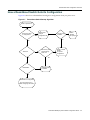
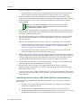
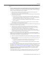
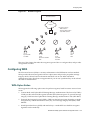
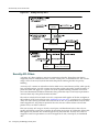
How a RoamAbout Switch Gets its Configuration ........................................................................................... 2-3
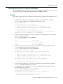
CLI quickstart Command ................................................................................................................................. 2-4
Quickstart Example ................................................................................................................................... 2-5
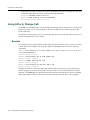
Remote Configuration...................................................................................................................................... 2-7
Opening the QuickStart Network Plan in RASM.............................................................................................. 2-8
ix
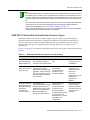
Chapter 3: Configuring AAA for Administrative and Local Access
Overview of AAA for Administrative and Local Access ................................................................................... 3-1
Before You Start .............................................................................................................................................. 3-3
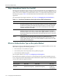
About Administrative Access ........................................................................................................................... 3-4
Access Modes........................................................................................................................................... 3-4
Types of Administrative Access ................................................................................................................3-4
First-Time Configuration Using the Console.................................................................................................... 3-5
Enabling an Administrator ......................................................................................................................... 3-5
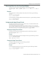
Setting the RoamAbout Switch Enable Password .................................................................................... 3-6
Setting the RoamAbout Switch Enable Password for the First Time.................................................. 3-6
RoamAbout Switch Manager Enable Password ................................................................................. 3-6
Authenticating at the Console ................................................................................................................... 3-7
Customizing AAA with “Globs” and Groups .............................................................................................. 3-7
Setting User Passwords............................................................................................................................ 3-8
Adding and Clearing Local Users for Administrative Access .................................................................... 3-8
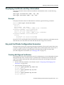
Example.............................................................................................................................................. 3-8
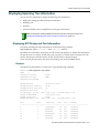
Configuring Accounting for Administrative Users ............................................................................................ 3-9
Examples .................................................................................................................................................. 3-9
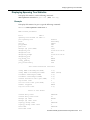
Displaying the AAA Configuration ................................................................................................................. 3-10
Saving the Configuration ............................................................................................................................... 3-10
Example .................................................................................................................................................. 3-10
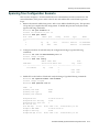
Administrative AAA Configuration Scenarios ................................................................................................ 3-11
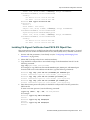
Local Authentication................................................................................................................................ 3-11
Example............................................................................................................................................ 3-11
Local Authentication for Console Users and RADIUS Authentication
for Telnet Users....................................................................................................................................... 3-11
Examples.......................................................................................................................................... 3-11
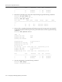
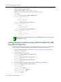
Local Override and Backup Local Authentication ................................................................................... 3-12
Example............................................................................................................................................ 3-12
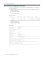
Authentication When RADIUS Servers Do Not Respond ....................................................................... 3-13
Example............................................................................................................................................ 3-13
Chapter 4: Configuring and Managing Ports and VLANs
Configuring and Managing Ports ..................................................................................................................... 4-1
Setting the Port Type ................................................................................................................................ 4-1
Configuring for a Distributed DAP ............................................................................................................. 4-3
Examples............................................................................................................................................ 4-3
Setting a Port for a Wired Authentication User ......................................................................................... 4-3
Example.............................................................................................................................................. 4-4
Clearing a Port .......................................................................................................................................... 4-4
Example.............................................................................................................................................. 4-5
Clearing a Distributed DAP ....................................................................................................................... 4-5
Configuring a Port Name........................................................................................................................... 4-5
Setting a Port Name ........................................................................................................................... 4-5
Example ....................................................................................................................................... 4-5
Removing a Port Name ...................................................................................................................... 4-5
Configuring Media Type on a Dual-Interface Gigabit Ethernet Port (RBT-8400 only) .............................. 4-6
Example.............................................................................................................................................. 4-6
Configuring Port Operating Parameters.................................................................................................... 4-7
10/100 Ports—Autonegotiation and Port Speed................................................................................. 4-7
Example ....................................................................................................................................... 4-7
Gigabit Ports—Autonegotiation and Flow Control .............................................................................. 4-8
x
Disabling or Reenabling a Port........................................................................................................... 4-8
Resetting a Port.................................................................................................................................. 4-8
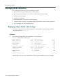
Displaying Port Information ....................................................................................................................... 4-9
Displaying Port Configuration and Status ........................................................................................... 4-9
Example ....................................................................................................................................... 4-9
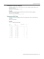
Displaying Port Statistics .................................................................................................................. 4-10
Example ..................................................................................................................................... 4-10
Clearing Statistics Counters ............................................................................................................. 4-10
Monitoring Port Statistics.................................................................................................................. 4-10
Example ..................................................................................................................................... 4-11
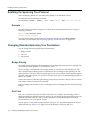
Configuring Load-Sharing Port Groups................................................................................................... 4-11
Load Sharing .................................................................................................................................... 4-11
Link Redundancy.............................................................................................................................. 4-12
Configuring a Port Group.................................................................................................................. 4-12
Examples ................................................................................................................................... 4-12
Removing a Port Group .................................................................................................................... 4-13
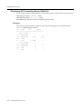
Displaying Port Group Information ................................................................................................... 4-13
Example ..................................................................................................................................... 4-13
Interoperating with Cisco Systems EtherChannel ............................................................................ 4-13
Configuring and Managing VLANs ................................................................................................................ 4-14
Understanding VLANs in Enterasys Networks MSS ............................................................................... 4-14
VLANs, IP Subnets, and IP Addressing ........................................................................................... 4-14
Users and VLANs ............................................................................................................................. 4-15
VLAN Names.................................................................................................................................... 4-15
Roaming and VLANs ........................................................................................................................ 4-15
Traffic Forwarding............................................................................................................................. 4-16
802.1Q Tagging................................................................................................................................ 4-16
Tunnel Affinity................................................................................................................................... 4-16
Configuring a VLAN ................................................................................................................................ 4-16
Creating a VLAN............................................................................................................................... 4-17
Example ..................................................................................................................................... 4-17
Adding Ports to a VLAN.................................................................................................................... 4-17
Examples ................................................................................................................................... 4-17
Removing an Entire VLAN or a VLAN Port ...................................................................................... 4-18
Examples ................................................................................................................................... 4-18
Changing Tunneling Affinity .................................................................................................................... 4-18
Restricting Layer 2 Forwarding Among Clients....................................................................................... 4-19
Examples.......................................................................................................................................... 4-19
Displaying VLAN Information .................................................................................................................. 4-20
Example............................................................................................................................................ 4-20
Managing the Layer 2 Forwarding Database ................................................................................................ 4-20
Types of Forwarding Database Entries................................................................................................... 4-20
How Entries Enter the Forwarding Database.......................................................................................... 4-21
Displaying Forwarding Database Information ......................................................................................... 4-21
Displaying the Size of the Forwarding Database.............................................................................. 4-21
Example ..................................................................................................................................... 4-21
Displaying Forwarding Database Entries .........................................................................................4-21
Example ..................................................................................................................................... 4-22
Adding an Entry to the Forwarding Database ......................................................................................... 4-22
Examples.......................................................................................................................................... 4-22
Removing Entries from the Forwarding Database ..................................................................................4-23
Examples.......................................................................................................................................... 4-23
Configuring the Aging Timeout Period .................................................................................................... 4-23
xi
Displaying the Aging Timeout Period ............................................................................................... 4-23
Example ..................................................................................................................................... 4-23
Changing the Aging Timeout Period................................................................................................. 4-23
Example ..................................................................................................................................... 4-23
Port and VLAN Configuration Scenario ......................................................................................................... 4-24
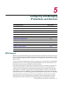
Chapter 5: Configuring and Managing IP Interfaces and Services
MTU Support ................................................................................................................................................... 5-1
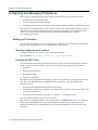
Configuring and Managing IP Interfaces ......................................................................................................... 5-2
Adding an IP Interface............................................................................................................................... 5-2
Statically Configuring an IP Interface ................................................................................................. 5-2
Enabling the DHCP Client .................................................................................................................. 5-2
How MSS Resolves Conflicts with Statically Configured IP Parameters ..................................... 5-3
Configuring the DHCP Client .............................................................................................................. 5-3
Example ....................................................................................................................................... 5-4
Displaying DHCP Client Information...................................................................................................5-4
Disabling or Reenabling an IP Interface.................................................................................................... 5-4
Removing an IP Interface ................................................................................................................... 5-4
Displaying IP Interface Information..................................................................................................... 5-4
Configuring the System IP Address................................................................................................................. 5-5
Designating the System IP Address.......................................................................................................... 5-5
Displaying the System IP Address ............................................................................................................ 5-5
Clearing the System IP Address ............................................................................................................... 5-5
Configuring and Managing IP Routes.............................................................................................................. 5-6
Displaying IP Routes................................................................................................................................. 5-7
Examples............................................................................................................................................ 5-7
Adding a Static Route ............................................................................................................................... 5-8
Examples............................................................................................................................................ 5-8
Removing a Static Route .......................................................................................................................... 5-9
Example.............................................................................................................................................. 5-9
Managing the Management Services .............................................................................................................. 5-9
Managing SSH .......................................................................................................................................... 5-9
Login Timeouts ................................................................................................................................... 5-9
Session Timeouts ............................................................................................................................. 5-10
Enabling SSH ................................................................................................................................... 5-10
Example ..................................................................................................................................... 5-10
Example ..................................................................................................................................... 5-10
Adding an SSH User ........................................................................................................................ 5-11
Examples ................................................................................................................................... 5-11
Changing the SSH Service Port Number ......................................................................................... 5-11
Changing SSH Timeouts .................................................................................................................. 5-11
Example ..................................................................................................................................... 5-11
Managing SSH Server Sessions ...................................................................................................... 5-12
Examples ................................................................................................................................... 5-12
Managing Telnet ..................................................................................................................................... 5-12
Telnet Login Timers .......................................................................................................................... 5-12
Enabling Telnet................................................................................................................................. 5-12
Adding a Telnet User........................................................................................................................ 5-13
Displaying Telnet Status................................................................................................................... 5-13
Example ..................................................................................................................................... 5-13
Changing the Telnet Service Port Number ....................................................................................... 5-13
Resetting the Telnet Service Port Number to Its Default .................................................................. 5-13
xii
Managing Telnet Server Sessions.................................................................................................... 5-14
Examples ................................................................................................................................... 5-14
Managing HTTPS.................................................................................................................................... 5-15
Enabling HTTPS............................................................................................................................... 5-15
Displaying HTTPS Information ......................................................................................................... 5-15
Example ..................................................................................................................................... 5-15
Changing the Idle Timeout for CLI Management Sessions..................................................................... 5-16
Examples.......................................................................................................................................... 5-16
Configuring and Managing DNS.................................................................................................................... 5-16
Enabling or Disabling the DNS Client ..................................................................................................... 5-16
Configuring DNS Servers........................................................................................................................ 5-17
Adding a DNS Server ....................................................................................................................... 5-17
Removing a DNS Server .................................................................................................................. 5-17
Configuring a Default Domain Name ...................................................................................................... 5-17
Adding the Default Domain Name .................................................................................................... 5-17
Removing the Default Domain Name ...............................................................................................5-17
Displaying DNS Server Information ........................................................................................................ 5-18
Example............................................................................................................................................ 5-18
Configuring and Managing Aliases................................................................................................................ 5-18
Adding an Alias ....................................................................................................................................... 5-18
Example............................................................................................................................................ 5-18
Removing an Alias .................................................................................................................................. 5-18
Displaying Aliases ................................................................................................................................... 5-19
Example............................................................................................................................................ 5-19
Configuring and Managing Time Parameters................................................................................................ 5-20
Setting the Time Zone............................................................................................................................. 5-20
Displaying the Time Zone ................................................................................................................. 5-21
Example ..................................................................................................................................... 5-21
Clearing the Time Zone .................................................................................................................... 5-21
Configuring the Summertime Period ....................................................................................................... 5-21
Displaying the Summertime Period .................................................................................................. 5-22
Example ..................................................................................................................................... 5-22
Clearing the Summertime Period ..................................................................................................... 5-22
Statically Configuring the System Time and Date................................................................................... 5-22
Displaying the Time and Date .......................................................................................................... 5-22
Configuring and Managing NTP..............................................................................................................5-23
Adding an NTP Server ............................................................................................................................ 5-23
Example............................................................................................................................................ 5-23
Removing an NTP Server ....................................................................................................................... 5-23
Changing the NTP Update Interval ......................................................................................................... 5-24
Example............................................................................................................................................ 5-24
Resetting the Update Interval to the Default ........................................................................................... 5-24
Enabling the NTP Client.......................................................................................................................... 5-24
Displaying NTP Information .................................................................................................................... 5-24
Example............................................................................................................................................ 5-24
Managing the ARP Table .............................................................................................................................. 5-25
Displaying ARP Table Entries ................................................................................................................. 5-25
Example............................................................................................................................................ 5-25
Adding an ARP Entry .............................................................................................................................. 5-25
Example............................................................................................................................................ 5-26
Changing the Aging Timeout................................................................................................................... 5-26
Example............................................................................................................................................ 5-26
Pinging Another Device ................................................................................................................................. 5-27
xiii
Example .................................................................................................................................................. 5-27
Logging In to a Remote Device ..................................................................................................................... 5-28
Examples ................................................................................................................................................ 5-28
Tracing a Route ............................................................................................................................................. 5-29
Example .................................................................................................................................................. 5-29
IP Interfaces and Services Configuration Scenario ....................................................................................... 5-30
Chapter 6: Configuring SNMP
Overview.......................................................................................................................................................... 6-1
Configuring SNMP........................................................................................................................................... 6-1
Setting the System Location and Contact Strings..................................................................................... 6-2
Examples............................................................................................................................................ 6-2
Enabling SNMP Versions.......................................................................................................................... 6-2
Example.............................................................................................................................................. 6-2
Configuring Community Strings (SNMPv1 and SNMPv2c Only) .............................................................. 6-2
Examples............................................................................................................................................ 6-3
Creating a USM User for SNMPv3............................................................................................................ 6-3
Examples............................................................................................................................................ 6-4
Setting SNMP Security.............................................................................................................................. 6-4
Example.............................................................................................................................................. 6-5
Configuring a Notification Profile............................................................................................................... 6-5
Examples............................................................................................................................................ 6-7
Configuring a Notification Target............................................................................................................... 6-8
Examples............................................................................................................................................ 6-9
Enabling the SNMP Service...................................................................................................................... 6-9
Example.............................................................................................................................................. 6-9
Displaying SNMP Information........................................................................................................................ 6-10
Displaying SNMP Version and Status Information.................................................................................. 6-10
Displaying the Configured SNMP Community Strings ............................................................................ 6-10
Displaying USM Settings......................................................................................................................... 6-10
Displaying Notification Profiles................................................................................................................ 6-10
Displaying Notification Targets................................................................................................................ 6-10
Displaying SNMP Statistics Counters ..................................................................................................... 6-10
Chapter 7: Configuring and Managing Mobility Domain Roaming
About the Mobility Domain Feature ................................................................................................................. 7-1
Configuring a Mobility Domain......................................................................................................................... 7-2
Configuring the Seed ................................................................................................................................ 7-2
Example.............................................................................................................................................. 7-2
Configuring Member RoamAbout Switches on the Seed.......................................................................... 7-3
Examples............................................................................................................................................ 7-3
Configuring a Member............................................................................................................................... 7-3
Example.............................................................................................................................................. 7-3
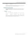
Displaying Mobility Domain Status............................................................................................................ 7-4
Example.............................................................................................................................................. 7-4
Displaying the Mobility Domain Configuration........................................................................................... 7-4
Examples............................................................................................................................................ 7-4
Clearing a Mobility Domain from a RoamAbout Switch ............................................................................ 7-4
Clearing a Mobility Domain Member from a Seed .................................................................................... 7-5
Configuring RBT-Switch to RBT-Switch Security ............................................................................................ 7-5
Monitoring the VLANs and Tunnels in a Mobility Domain ............................................................................... 7-5
Displaying Roaming Stations .................................................................................................................... 7-6
xiv
Example.............................................................................................................................................. 7-6
Displaying Roaming VLANs and Their Affinities ....................................................................................... 7-6
Example.............................................................................................................................................. 7-6
Displaying Tunnel Information................................................................................................................... 7-7
Example.............................................................................................................................................. 7-7
Understanding the Sessions of Roaming Users.............................................................................................. 7-8
Requirements for Roaming to Succeed .................................................................................................... 7-8
Effects of Timers on Roaming................................................................................................................... 7-9
Monitoring Roaming Sessions .................................................................................................................. 7-9
Example.............................................................................................................................................. 7-9
Mobility Domain Scenario.............................................................................................................................. 7-10
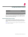
Chapter 8: Configuring Network Domains
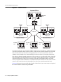
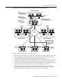
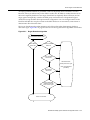
About the Network Domain Feature ................................................................................................................8-1
Network Domain Seed Affinity .................................................................................................................. 8-4
Configuring a Network Domain........................................................................................................................ 8-5
Configuring Network Domain Seeds ......................................................................................................... 8-5
Examples............................................................................................................................................ 8-5
Specifying Network Domain Seed Peers .................................................................................................. 8-6
Example.............................................................................................................................................. 8-6
Configuring Network Domain Members .................................................................................................... 8-6
Examples............................................................................................................................................ 8-7
Displaying Network Domain Information ...................................................................................................8-7
Examples............................................................................................................................................ 8-7
Clearing Network Domain Configuration from a RoamAbout Switch ........................................................ 8-8
Clearing a Network Domain Seed from a RoamAbout Switch ........................................................... 8-8
Clearing a Network Domain Peer from a Network Domain Seed ............................................................. 8-8
Clearing Network Domain Seed or Member Configuration from a RoamAbout Switch ............................8-8
Network Domain Scenario............................................................................................................................... 8-9
Chapter 9: Configuring Access Points
AP Overview.................................................................................................................................................... 9-1
Country of Operation................................................................................................................................. 9-3
Distributed APs ......................................................................................................................................... 9-3
Distributed AP Network Requirements ............................................................................................... 9-3
Distributed APs and STP.................................................................................................................... 9-4
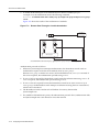
Distributed APs and DHCP Option 43 ................................................................................................ 9-4
AP Parameters ................................................................................................................................... 9-5
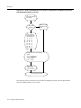
Boot Process for APs ................................................................................................................................ 9-6
Establishing Connectivity on the Network .......................................................................................... 9-6
How an AP Obtains an IP Address through DHCP......................................................................9-6
Static IP Address Configuration for APs ...................................................................................... 9-6
Contacting a RoamAbout Switch ........................................................................................................ 9-7
How an AP Contacts a RoamAbout Switch (DHCP-Obtained Address)...................................... 9-7
How a Distributed AP Contacts an RBT Switch (Statically Configured Address) ........................ 9-8
Loading and Activating an Operational Image.................................................................................. 9-10
Obtaining Configuration Information from the RBT Switch ............................................................... 9-10
AP Boot Examples............................................................................................................................ 9-10
Example AP Boot over Layer 2 Network.................................................................................... 9-11
Example AP Boot over a Layer 3 Network................................................................................. 9-12
Example Boot of AP with Static IP Configuration....................................................................... 9-13
Session Load Balancing ................................................................................................................... 9-14
Service Profiles ....................................................................................................................................... 9-14
xv
Public and Private SSIDs ................................................................................................................. 9-17
Encryption......................................................................................................................................... 9-18
Radio Profiles.......................................................................................................................................... 9-18
RF Auto-Tuning ................................................................................................................................ 9-19
Default Radio Profile......................................................................................................................... 9-19
Radio-Specific Parameters............................................................................................................... 9-20
Configuring Access Points............................................................................................................................. 9-21
Specifying the Country of Operation ....................................................................................................... 9-22
Examples.......................................................................................................................................... 9-25
Configuring an Auto-DAP Profile for Automatic AP Configuration .......................................................... 9-26
How an Unconfigured AP Finds a RoamAbout Switch To Configure It ............................................ 9-26
Configured APs Have Precedence Over Unconfigured APs ............................................................ 9-26
Configuring a Auto-AP Profile........................................................................................................... 9-27
Examples ................................................................................................................................... 9-27
Changing AP Parameter Values....................................................................................................... 9-28
Enabling the Auto-AP Profile...................................................................................................... 9-28
Specifying the Radio Profile Used by the Auto-AP Profile ......................................................... 9-29
Displaying Status Information for APs Configured by the Auto-AP Profile................................. 9-29
Converting an AP Configured by the Auto-AP Profile into a Permanent AP.............................. 9-30
Configuring AP Port Parameters............................................................................................................. 9-30
Configuring an Indirectly Connected AP........................................................................................... 9-31
Example ..................................................................................................................................... 9-31
Configuring Static IP Addresses on Distributed APs ........................................................................ 9-31
Specifying IP Information ........................................................................................................... 9-31
Specifying RoamAbout Switch Information ................................................................................ 9-32
Specifying VLAN information ..................................................................................................... 9-32
Clearing an AP from the Configuration ............................................................................................. 9-33
Changing AP Names ........................................................................................................................ 9-33
Changing Bias .................................................................................................................................. 9-33
Example ..................................................................................................................................... 9-33
Configuring a Load-Balancing Group ............................................................................................... 9-34
Example ..................................................................................................................................... 9-34
Disabling or Reenabling Automatic Firmware Upgrades .................................................................. 9-34
Forcing an AP To Download its Operational Image from the RoamAbout Switch............................ 9-34
Enabling LED Blink Mode ................................................................................................................. 9-35
Configuring AP- RoamAbout Switch Security ......................................................................................... 9-35
Encryption Key Fingerprint ............................................................................................................... 9-35
Encryption Options ........................................................................................................................... 9-36
Verifying an AP’s Fingerprint on a RoamAbout Switch .................................................................... 9-37
Finding the Fingerprint ............................................................................................................... 9-37
Verifying a Fingerprint on the Switch ......................................................................................... 9-38
Setting the AP Security Requirement on a RoamAbout Switch ....................................................... 9-38
Example ..................................................................................................................................... 9-38
Fingerprint Log Message.................................................................................................................. 9-38
Configuring a Service Profile................................................................................................................... 9-39
Creating a Service Profile ................................................................................................................. 9-39
Example ..................................................................................................................................... 9-39
Removing a Service Profile .............................................................................................................. 9-39
Changing a Service Profile Setting ................................................................................................... 9-39
Disabling or Reenabling Encryption for an SSID .............................................................................. 9-40
Disabling or Reenabling Beaconing of an SSID ............................................................................... 9-40
Changing the Fallthru Authentication Type ...................................................................................... 9-40
Changing Transmit Rates ................................................................................................................. 9-41
xvi
Example ..................................................................................................................................... 9-42
Disabling Idle-Client Probing ............................................................................................................ 9-42
Example ..................................................................................................................................... 9-42
Changing the User Idle Timeout ....................................................................................................... 9-42
Example ..................................................................................................................................... 9-42
Changing the Short Retry Threshold ................................................................................................ 9-43
Example ..................................................................................................................................... 9-43
Changing the Long Retry Threshold................................................................................................. 9-43
Example ..................................................................................................................................... 9-43
Configuring a Radio Profile ..................................................................................................................... 9-43
Creating a New Profile...................................................................................................................... 9-44
Example ..................................................................................................................................... 9-44
Changing Radio Parameters ............................................................................................................ 9-44
Changing the Beacon Interval.................................................................................................... 9-44
Changing the DTIM Interval ....................................................................................................... 9-45
Changing the RTS Threshold.....................................................................................................9-45
Changing the Fragmentation Threshold..................................................................................... 9-46
Changing the Maximum Receive Threshold .............................................................................. 9-46
Changing the Maximum Transmit Threshold ............................................................................. 9-46
Changing the Preamble Length ................................................................................................. 9-47
Resetting a Radio Profile Parameter to its Default Value ................................................................. 9-48
Example ..................................................................................................................................... 9-48
Removing a Radio Profile ................................................................................................................. 9-48
Example ..................................................................................................................................... 9-48
Configuring Radio-Specific Parameters .................................................................................................. 9-49
Configuring the Channel and Transmit Power.................................................................................. 9-49
Examples ................................................................................................................................... 9-49
Configuring the External Antenna Model and Location .................................................................... 9-50
Specifying the External Antenna Model ..................................................................................... 9-50
Specifying the External Antenna Location ................................................................................. 9-50
Mapping the Radio Profile to Service Profiles......................................................................................... 9-51
Example............................................................................................................................................ 9-51
Assigning a Radio Profile and Enabling Radios...................................................................................... 9-51
Examples.......................................................................................................................................... 9-51
Disabling or Reenabling Radios .................................................................................................................... 9-52
Enabling or Disabling Individual Radios.................................................................................................. 9-52
Example............................................................................................................................................ 9-52
Disabling or Reenabling All Radios Using a Profile ................................................................................ 9-52
Examples.......................................................................................................................................... 9-52
Resetting a Radio to its Factory Default Settings.................................................................................... 9-53
Example............................................................................................................................................ 9-53
Restarting an AP ........................................................................................................................................... 9-53
Displaying AP Information ............................................................................................................................. 9-54
Displaying AP Configuration Information ................................................................................................ 9-54
Examples.......................................................................................................................................... 9-54
Displaying Active Connection Information for Distributed APs................................................................ 9-55
Example............................................................................................................................................ 9-55
Displaying a List of Distributed APs that Are Not Configured ................................................................. 9-56
Example............................................................................................................................................ 9-56
Displaying Connection Information for Distributed APs ..........................................................................9-56
Displaying Service Profile Information .................................................................................................... 9-57
Example............................................................................................................................................ 9-57
Displaying Radio Profile Information ....................................................................................................... 9-58
xvii
Example............................................................................................................................................ 9-58
Displaying AP Status Information............................................................................................................ 9-59
Example............................................................................................................................................ 9-59
Displaying Static IP Address Information for Distributed APs ................................................................. 9-60
Example............................................................................................................................................ 9-60
Displaying AP Statistics Counters........................................................................................................... 9-60
Example............................................................................................................................................ 9-60
Chapter 10: Configuring User Encryption
Configuring WPA ........................................................................................................................................... 10-3
WPA Cipher Suites ................................................................................................................................. 10-3
TKIP Countermeasures........................................................................................................................... 10-5
WPA Authentication Methods ................................................................................................................. 10-6
WPA Information Element....................................................................................................................... 10-6
Client Support ......................................................................................................................................... 10-7
Configuring WPA..................................................................................................................................... 10-7
Creating a Service Profile for WPA .................................................................................................. 10-8
Enabling WPA .................................................................................................................................. 10-8
Specifying the WPA Cipher Suites ................................................................................................... 10-8
Example ..................................................................................................................................... 10-8
Changing the TKIP Countermeasures Timer Value ......................................................................... 10-9
Example ..................................................................................................................................... 10-9
Enabling PSK Authentication............................................................................................................ 10-9
Example ..................................................................................................................................... 10-9
Configuring a Global PSK Passphrase or Raw Key for All Clients ................................................... 10-9
Examples ................................................................................................................................... 10-9
Disabling 802.1X Authentication for WPA ...................................................................................... 10-10
Example ................................................................................................................................... 10-10
Displaying WPA Settings................................................................................................................ 10-10
Example ................................................................................................................................... 10-10
Assigning the Service Profile to Radios and Enabling the Radios ................................................. 10-11
Examples ................................................................................................................................. 10-11
Configuring RSN (802.11i) .......................................................................................................................... 10-12
Creating a Service Profile for RSN........................................................................................................ 10-12
Example.......................................................................................................................................... 10-12
Enabling RSN........................................................................................................................................ 10-12
Example.......................................................................................................................................... 10-12
Specifying the RSN Cipher Suites ........................................................................................................ 10-13
Example.......................................................................................................................................... 10-13
Changing the TKIP Countermeasures Timer Value.............................................................................. 10-13
Enabling PSK Authentication ................................................................................................................ 10-13
Displaying RSN Settings ....................................................................................................................... 10-13
Assigning the Service Profile to Radios and Enabling the Radios ........................................................ 10-14
Example.......................................................................................................................................... 10-14
Configuring WEP ......................................................................................................................................... 10-15
Setting Static WEP Key Values............................................................................................................. 10-16
Example.......................................................................................................................................... 10-17
Assigning Static WEP Keys .................................................................................................................. 10-17
Examples........................................................................................................................................ 10-17
Encryption Configuration Scenarios ............................................................................................................10-18
Enabling WPA with TKIP....................................................................................................................... 10-18
xviii
Enabling Dynamic WEP in a WPA Network..........................................................................................10-20
Configuring Encryption for MAC Clients................................................................................................ 10-22
Chapter 11: Configuring RF Auto-Tuning
RF Auto-Tuning Overview ............................................................................................................................. 11-1
Initial Channel and Power Assignment ................................................................................................... 11-1
How Channels Are Selected............................................................................................................. 11-2
Channel and Power Tuning..................................................................................................................... 11-2
Power Tuning ................................................................................................................................... 11-3
Channel Tuning ................................................................................................................................ 11-3
Tuning the Transmit Data Rate ........................................................................................................ 11-4
ARF Auto-Tuning Parameters................................................................................................................. 11-5
Changing RF Auto-Tuning Settings............................................................................................................... 11-6
Changing Channel Tuning Settings ........................................................................................................ 11-6
Disabling or Reenabling Channel Tuning ......................................................................................... 11-6
Example ..................................................................................................................................... 11-6
Changing the Channel Tuning Interval ............................................................................................. 11-6
Example ..................................................................................................................................... 11-6
Changing the Channel Holddown Interval ........................................................................................ 11-7
Example ..................................................................................................................................... 11-7
Changing Power Tuning Settings............................................................................................................ 11-7
Enabling Power Tuning .................................................................................................................... 11-7
Example ..................................................................................................................................... 11-7
Changing the Power Tuning Interval ................................................................................................ 11-7
Example ..................................................................................................................................... 11-7
Changing the Maximum Default Power Allowed On a Radio ........................................................... 11-8
Example ..................................................................................................................................... 11-8
Locking Down Tuned Settings....................................................................................................................... 11-8
Displaying RF Auto-Tuning Information......................................................................................................... 11-9
Displaying RF Auto-Tuning Settings ....................................................................................................... 11-9
Examples.......................................................................................................................................... 11-9
Displaying RF Neighbors ...................................................................................................................... 11-10
Example.......................................................................................................................................... 11-10
Displaying RF Attributes........................................................................................................................ 11-10
Example.......................................................................................................................................... 11-10
Chapter 12: Configuring Quality of Service
About QoS ..................................................................................................................................................... 12-1
Summary of QoS Features ..................................................................................................................... 12-1
QoS Mode ............................................................................................................................................... 12-3
WMM QoS Mode .............................................................................................................................. 12-4
WMM QoS on the RoamAbout Switch ............................................................................................. 12-9
WMM QoS on a RoamAbout Access Point .................................................................................... 12-10
SVP QoS Mode..................................................................................................................................... 12-12
U-APSD Support ................................................................................................................................... 12-13
Call Admission Control.......................................................................................................................... 12-13
Broadcast Control ................................................................................................................................. 12-13
Static CoS ............................................................................................................................................. 12-14
Overriding CoS...................................................................................................................................... 12-14
Changing QoS Settings ............................................................................................................................... 12-15
Changing the QoS Mode....................................................................................................................... 12-15
Example.......................................................................................................................................... 12-15
Enabling U-APSD Support .................................................................................................................... 12-15
xix
Configuring Call Admission Control ...................................................................................................... 12-15
Enabling CAC ................................................................................................................................. 12-16
Example ................................................................................................................................... 12-16
Changing the Maximum Number of Active Sessions ..................................................................... 12-16
Example ................................................................................................................................... 12-16
Configuring Static CoS.......................................................................................................................... 12-16
Examples........................................................................................................................................ 12-16
Changing CoS Mappings ...................................................................................................................... 12-17
Examples........................................................................................................................................ 12-17
Enabling Broadcast Control .................................................................................................................. 12-17
Examples........................................................................................................................................ 12-17
Displaying QoS Information......................................................................................................................... 12-18
Displaying a Radio Profile’s QoS Settings ............................................................................................ 12-18
Example.......................................................................................................................................... 12-18
Displaying a Service Profile’s QoS Settings.......................................................................................... 12-19
Example.......................................................................................................................................... 12-19
Displaying CoS Mappings ..................................................................................................................... 12-20
Displaying the Default CoS Mappings ............................................................................................12-20
Example ................................................................................................................................... 12-20
Displaying a DSCP-to-CoS Mapping .............................................................................................. 12-20
Example ................................................................................................................................... 12-20
Displaying a CoS-to-DSCP Mapping .............................................................................................. 12-21
Example ................................................................................................................................... 12-21
Displaying the DSCP Table ............................................................................................................12-21
Example ................................................................................................................................... 12-21
Displaying AP Forwarding Queue Statistics.......................................................................................... 12-22
Example.......................................................................................................................................... 12-22
Chapter 13: Configuring and Managing Spanning Tree Protocol
Spanning Overview ....................................................................................................................................... 13-1
Enabling the Spanning Tree Protocol............................................................................................................ 13-2
Example .................................................................................................................................................. 13-2
Changing Standard Spanning Tree Parameters ........................................................................................... 13-2
Bridge Priority.......................................................................................................................................... 13-2
Port Cost ................................................................................................................................................. 13-2
Port Priority ............................................................................................................................................. 13-3
Changing the Bridge Priority ................................................................................................................... 13-3
Example............................................................................................................................................ 13-3
Changing STP Port Parameters..............................................................................................................13-4
Changing the STP Port Cost ............................................................................................................ 13-4
Examples ................................................................................................................................... 13-4
Resetting the STP Port Cost to the Default Value ............................................................................ 13-4
Examples ................................................................................................................................... 13-4
Changing the STP Port Priority ........................................................................................................ 13-5
Examples ................................................................................................................................... 13-5
Resetting the STP Port Priority to the Default Value ........................................................................ 13-6
Changing Spanning Tree Timers ............................................................................................................ 13-6
Changing the STP Hello Interval ...................................................................................................... 13-6
Example ..................................................................................................................................... 13-6
Changing the STP Forwarding Delay ............................................................................................... 13-6
Example ..................................................................................................................................... 13-6
xx
Changing the STP Maximum Age .................................................................................................... 13-7
Example ..................................................................................................................................... 13-7
Configuring and Managing STP Fast Convergence Features....................................................................... 13-7
Port Fast Convergence ........................................................................................................................... 13-7
Backbone Fast Convergence.................................................................................................................. 13-8
Uplink Fast Convergence........................................................................................................................ 13-8
Configuring Port Fast Convergence........................................................................................................ 13-8
Example............................................................................................................................................ 13-8
Displaying Port Fast Convergence Information....................................................................................... 13-9
Example............................................................................................................................................ 13-9
Configuring Backbone Fast Convergence .............................................................................................. 13-9
Example............................................................................................................................................ 13-9
Displaying the Backbone Fast Convergence State.................................................................................13-9
Example............................................................................................................................................ 13-9
Configuring Uplink Fast Convergence .................................................................................................. 13-10
Displaying Uplink Fast Convergence Information .................................................................................13-10
Example.......................................................................................................................................... 13-10
Displaying Spanning Tree Information ........................................................................................................ 13-11
Displaying STP Bridge and Port Information......................................................................................... 13-11
Example.......................................................................................................................................... 13-11
Displaying the STP Port Cost on a VLAN Basis ...................................................................................13-12
Example.......................................................................................................................................... 13-12
Displaying Blocked STP Ports .............................................................................................................. 13-12
Example.......................................................................................................................................... 13-12
Displaying Spanning Tree Statistics...................................................................................................... 13-13
Example.......................................................................................................................................... 13-13
Clearing STP Statistics ......................................................................................................................... 13-14
Spanning Tree Configuration Scenario ....................................................................................................... 13-15
Chapter 14: Configuring and Managing IGMP Snooping
Disabling or Reenabling IGMP Snooping ...................................................................................................... 14-1
Disabling or Reenabling Proxy Reporting...................................................................................................... 14-2
Enabling the Pseudo-Querier ........................................................................................................................ 14-2
Changing IGMP Timers ................................................................................................................................. 14-2
Changing the Query Interval ................................................................................................................... 14-3
Changing the Other-Querier-Present Interval ......................................................................................... 14-3
Changing the Query Response Interval .................................................................................................. 14-3
Changing the Last Member Query Interval ............................................................................................. 14-3
Changing Robustness............................................................................................................................. 14-3
Enabling Router Solicitation .......................................................................................................................... 14-3
Changing the Router Solicitation Interval................................................................................................ 14-4
Configuring Static Multicast Ports.................................................................................................................. 14-4
Adding or Removing a Static Multicast Router Port ................................................................................ 14-4
Adding or Removing a Static Multicast Receiver Port............................................................................. 14-4
Displaying Multicast Information.................................................................................................................... 14-4
Displaying Multicast Configuration Information and Statistics................................................................. 14-5
Example............................................................................................................................................ 14-5
Displaying Multicast Statistics Only .................................................................................................. 14-6
Clearing Multicast Statistics.............................................................................................................. 14-6
Displaying Multicast Queriers.................................................................................................................. 14-6
Example............................................................................................................................................ 14-6
Displaying Multicast Routers................................................................................................................... 14-7
Example............................................................................................................................................ 14-7
xxi
Displaying Multicast Receivers ............................................................................................................... 14-7
Example............................................................................................................................................ 14-7
Chapter 15: Configuring and Managing Security ACLs
About Security Access Control Lists..............................................................................................................15-1
Overview of Security ACL Commands.................................................................................................... 15-1
Security ACL Filters ................................................................................................................................ 15-2
Order in Which ACLs are Applied to Traffic ............................................................................................ 15-3
Traffic Direction ................................................................................................................................ 15-3
Selection of User ACLs ........................................................................................................................... 15-3
Creating and Committing a Security ACL...................................................................................................... 15-4
Setting a Source IP ACL ......................................................................................................................... 15-4
Examples.......................................................................................................................................... 15-4
Wildcard Masks ................................................................................................................................ 15-5
Class of Service................................................................................................................................ 15-5
Setting an ICMP ACL .............................................................................................................................. 15-6
Example............................................................................................................................................ 15-6
Setting TCP and UDP ACLs ................................................................................................................... 15-7
Setting a TCP ACL ........................................................................................................................... 15-8
Example ..................................................................................................................................... 15-8
Setting a UDP ACL........................................................................................................................... 15-8
Example ..................................................................................................................................... 15-8
Determining the ACE Order .................................................................................................................... 15-9
Committing a Security ACL ..................................................................................................................... 15-9
Examples.......................................................................................................................................... 15-9
Viewing Security ACL Information........................................................................................................... 15-9
Example............................................................................................................................................ 15-9
Viewing the Edit Buffer ................................................................................................................... 15-10
Example ................................................................................................................................... 15-10
Viewing Committed Security ACLs ................................................................................................. 15-10
Viewing Security ACL Details ......................................................................................................... 15-11
Examples ................................................................................................................................. 15-11
Displaying Security ACL Hits .......................................................................................................... 15-11
Examples ................................................................................................................................. 15-11
Clearing Security ACLs ......................................................................................................................... 15-12
Examples........................................................................................................................................ 15-12
Mapping Security ACLs ............................................................................................................................... 15-13
Mapping User-Based Security ACLs..................................................................................................... 15-13
Example.......................................................................................................................................... 15-13
Mapping Security ACLs to VLANs, Virtual Ports, or Distributed APs.................................................... 15-14
Example.......................................................................................................................................... 15-14
Displaying ACL Maps to VLANs and Virtual Ports ................................................................................ 15-15
Example.......................................................................................................................................... 15-15
Clearing a Security ACL Map................................................................................................................ 15-15
Examples........................................................................................................................................ 15-15
Modifying a Security ACL ............................................................................................................................ 15-16
Adding Another ACE to a Security ACL ................................................................................................ 15-16
Example.......................................................................................................................................... 15-16
Placing One ACE before Another ......................................................................................................... 15-17
Example.......................................................................................................................................... 15-17
Modifying an Existing Security ACL ...................................................................................................... 15-18
Example.......................................................................................................................................... 15-18
xxii
Clearing Security ACLs from the Edit Buffer ......................................................................................... 15-19
Example.......................................................................................................................................... 15-19
Using ACLs to Change CoS ........................................................................................................................ 15-20
Example ................................................................................................................................................ 15-20
Filtering Based on DSCP Values .......................................................................................................... 15-21
Using the dscp Option .................................................................................................................... 15-21
Example ................................................................................................................................... 15-21
Using the precedence and ToS Options......................................................................................... 15-22
Example ................................................................................................................................... 15-22
Enabling Prioritization for Legacy Voice over IP.......................................................................................... 15-23
General Guidelines ............................................................................................................................... 15-23
Enabling VoIP Support for TeleSym VoIP............................................................................................. 15-24
Enabling SVP Optimization for SpectraLink Phones............................................................................. 15-24
Known Limitations .......................................................................................................................... 15-25
Configuring a Service Profile for RSN (WPA2)............................................................................... 15-25
Example ................................................................................................................................... 15-25
Configuring a Service Profile for WPA............................................................................................ 15-26
Example ................................................................................................................................... 15-26
Configuring a Radio Profile............................................................................................................. 15-26
Example ................................................................................................................................... 15-26
Configuring a VLAN and AAA for Voice Clients ............................................................................. 15-27
Example ................................................................................................................................... 15-27
Configuring an ACL to Prioritize Voice Traffic ................................................................................ 15-27
Example ................................................................................................................................... 15-28
Setting 802.11b/g Radios to 802.11b (for Siemens SpectraLink VoIP Phones only) ..................... 15-28
Disabling RF Auto-Tuning Before Upgrading a SpectraLink Phone ............................................... 15-28
Example ................................................................................................................................... 15-28
Restricting Client-To-Client Forwarding Among IP-Only Clients ................................................................. 15-28
Security ACL Configuration Scenario .......................................................................................................... 15-29
Chapter 16: Managing Keys and Certificates
Why Use Keys and Certificates? ................................................................................................................... 16-1
Wireless Security through TLS................................................................................................................ 16-2
PEAP-MS-CHAP-V2 Security ................................................................................................................. 16-2
About Keys and Certificates .......................................................................................................................... 16-2
Public Key Infrastructures ....................................................................................................................... 16-3
Public and Private Keys .......................................................................................................................... 16-3
Digital Certificates ................................................................................................................................... 16-3
PKCS #7, PKCS #10, and PKCS #12 Object Files................................................................................. 16-4
Certificates Automatically Generated by MSS............................................................................................... 16-5
Creating Keys and Certificates ...................................................................................................................... 16-5
Choosing the Appropriate Certificate Installation Method for Your Network ........................................... 16-6
Creating Public-Private Key Pairs ........................................................................................................... 16-7
Example............................................................................................................................................ 16-7
Generating Self-Signed Certificates........................................................................................................ 16-7
Example............................................................................................................................................ 16-7
Installing a Key Pair and Certificate from a PKCS #12 Object File ......................................................... 16-8
Creating a CSR and Installing a Certificate from a PKCS #7 Object File ............................................... 16-9
Installing a CA’s Own Certificate........................................................................................................... 16-10
Displaying Certificate and Key Information.................................................................................................. 16-11
Example ................................................................................................................................................ 16-11
Key and Certificate Configuration Scenarios...............................................................................................16-11
Creating Self-Signed Certificates .......................................................................................................... 16-11
xxiii
Installing CA-Signed Certificates from PKCS #12 Object Files............................................................. 16-13
Installing CA-Signed Certificates Using a PKCS #10 Object File (CSR) and a PKCS #7 Object File .. 16-14
Chapter 17: Configuring AAA for Network Users
About AAA for Network Users ....................................................................................................................... 17-1
Authentication ......................................................................................................................................... 17-2
Authentication Types ........................................................................................................................ 17-2
Authentication Algorithm................................................................................................................... 17-3
SSID Name “Any” ............................................................................................................................. 17-5
Last-Resort Processing .................................................................................................................... 17-5
User Credential Requirements ......................................................................................................... 17-5
Authorization ........................................................................................................................................... 17-6
Accounting .............................................................................................................................................. 17-7
Summary of AAA Features ..................................................................................................................... 17-7
AAA Tools for Network Users........................................................................................................................ 17-8
“Globs” and Groups for Network User Classification .............................................................................. 17-8
Wildcard “Any” for SSID Matching .................................................................................................... 17-8
AAA Methods for IEEE 802.1X and Web Network Access ..................................................................... 17-8
AAA Rollover Process ...................................................................................................................... 17-9
Local Override Exception ................................................................................................................. 17-9
Remote Authentication with Local Backup ....................................................................................... 17-9
Example ..................................................................................................................................... 17-9
IEEE 802.1X Extensible Authentication Protocol Types ....................................................................... 17-11
Ways a RoamAbout Switch Can Use EAP ........................................................................................... 17-12
Effects of Authentication Type on Encryption Method .......................................................................... 17-12
Configuring 802.1X Authentication .............................................................................................................. 17-13
Example ................................................................................................................................................ 17-13
Configuring EAP Offload ....................................................................................................................... 17-14
Example.......................................................................................................................................... 17-14
Using Pass-Through ............................................................................................................................. 17-14
Example.......................................................................................................................................... 17-14
Authenticating via a Local Database..................................................................................................... 17-14
Example.......................................................................................................................................... 17-14
Binding User Authentication to Machine Authentication ....................................................................... 17-15
Authentication Rule Requirements ................................................................................................. 17-15
Bonded Auth Period ....................................................................................................................... 17-16
Bonded Auth Configuration Example ............................................................................................. 17-17
Displaying Bonded Auth Configuration Information ........................................................................ 17-17
Example ................................................................................................................................... 17-17
Configuring Authentication and Authorization by MAC Address ................................................................. 17-19
Adding and Clearing MAC Users and User Groups Locally..................................................................17-19
Adding MAC Users and Groups ..................................................................................................... 17-19
Examples ................................................................................................................................. 17-19
Clearing MAC Users and Groups ................................................................................................... 17-20
Examples ................................................................................................................................. 17-20
Configuring MAC Authentication and Authorization .............................................................................. 17-20
Examples........................................................................................................................................ 17-20
Changing the MAC Authorization Password for RADIUS ..................................................................... 17-21
Example.......................................................................................................................................... 17-21
Configuring Web Web Portal WebAAA ....................................................................................................... 17-22
How Web Web Portal WebAAA Works ................................................................................................. 17-22
Display of the Login Page............................................................................................................... 17-23
xxiv
WebAAA Requirements and Recommendations .................................................................................. 17-24
RoamAbout Switch Requirements..................................................................................................17-24
Portal ACL and User ACLs............................................................................................................. 17-26
Network Requirements ................................................................................................................... 17-27
RoamAbout Switch Recommendations .......................................................................................... 17-27
Client NIC Requirements................................................................................................................ 17-27
Client Web Browser Recommendations ......................................................................................... 17-27
Configuring Web Portal WebAAA ......................................................................................................... 17-28
Web Portal WebAAA Configuration Example ................................................................................. 17-28
Displaying Session Information for Web Portal WebAAA Users .................................................... 17-29
Using a Custom Login Page ................................................................................................................. 17-30
Copying and Modifying the Enterasys Login Page ......................................................................... 17-31
Custom Login Page Scenario......................................................................................................... 17-31
Using Dynamic Fields in WebAAA Redirect URLs................................................................................ 17-33
Examples ................................................................................................................................. 17-33
Configuring the Web Portal WebAAA Session Timeout Period ............................................................ 17-35
Configuring Last-Resort Access .................................................................................................................. 17-36
Examples .............................................................................................................................................. 17-36
Configuring AAA for Users of Third-Party APs ............................................................................................ 17-37
Requirements........................................................................................................................................ 17-38
Third-Party AP Requirements......................................................................................................... 17-38
RoamAbout Switch Requirements..................................................................................................17-38
RADIUS Server Requirements ....................................................................................................... 17-39
Configuring Authentication for 802.1X Users of a Third-Party AP with Tagged SSIDs......................... 17-39
Examples ................................................................................................................................. 17-40
Configuring Authentication for Non-802.1X Users of a Third-Party AP with Tagged SSIDs................. 17-41
Configuring Access for Any Users of a Non-Tagged SSID ................................................................... 17-41
Assigning Authorization Attributes............................................................................................................... 17-42
Assigning Attributes to Users and Groups ............................................................................................ 17-45
Assigning SSID Default Attributes to a Service Profile .........................................................................17-47
Assigning a Security ACL to a User or a Group.................................................................................... 17-48
Assigning a Security ACL Locally................................................................................................... 17-48
Examples ................................................................................................................................. 17-48
Assigning a Security ACL on a RADIUS Server ............................................................................. 17-49
Clearing a Security ACL from a User or Group .............................................................................. 17-49
Assigning Encryption Types to Wireless Users..................................................................................... 17-49
Assigning and Clearing Encryption Types Locally.......................................................................... 17-49
Examples ................................................................................................................................. 17-50
Assigning and Clearing Encryption Types on a RADIUS Server.................................................... 17-50
Keeping Users on the Same VLAN Even After Roaming...................................................................... 17-50
Overriding or Adding Attributes Locally with a Location Policy.................................................................... 17-52
About the Location Policy...................................................................................................................... 17-52
How the Location Policy Differs from a Security ACL ........................................................................... 17-52
Setting the Location Policy.................................................................................................................... 17-53
Examples........................................................................................................................................ 17-53
Applying Security ACLs in a Location Policy Rule ................................................................................ 17-54
Examples........................................................................................................................................ 17-54
Displaying and Positioning Location Policy Rules................................................................................. 17-54
Example.......................................................................................................................................... 17-54
Clearing Location Policy Rules and Disabling the Location Policy ....................................................... 17-55
Configuring Accounting for Wireless Network Users................................................................................... 17-55
Configuring Periodic Accounting Update Records ................................................................................ 17-56
Enabling System Accounting Messages ...............................................................................................17-56
xxv
Viewing Local Accounting Records....................................................................................................... 17-57
Viewing Roaming Accounting Records ................................................................................................. 17-57
Example.......................................................................................................................................... 17-57
Displaying the AAA Configuration ............................................................................................................... 17-60
Example ................................................................................................................................................ 17-60
Avoiding AAA Problems in Configuration Order .......................................................................................... 17-61
Using the Wildcard “Any” as the SSID Name in Authentication Rules.................................................. 17-61
Example ................................................................................................................................................ 17-61
Using Authentication and Accounting Rules Together.......................................................................... 17-62
Configuration Producing an Incorrect Processing Order ................................................................ 17-62
Configuration for a Correct Processing Order ................................................................................ 17-62
Example ................................................................................................................................... 17-62
Configuring a Mobility Profile....................................................................................................................... 17-63
Examples .............................................................................................................................................. 17-63
Network User Configuration Scenarios ....................................................................................................... 17-64
General Use of Network User Commands............................................................................................ 17-65
Enabling RADIUS Pass-Through Authentication .................................................................................. 17-66
Enabling PEAP-MS-CHAP-V2 Authentication ...................................................................................... 17-67
Enabling PEAP-MS-CHAP-V2 Offload.................................................................................................. 17-67
Combining EAP Offload with Pass-Through Authentication ................................................................. 17-68
Overriding AAA-Assigned VLANs ......................................................................................................... 17-68
Chapter 18: Configuring Communication with RADIUS
RADIUS Overview ......................................................................................................................................... 18-1
Before You Begin .......................................................................................................................................... 18-2
Configuring RADIUS Servers ........................................................................................................................ 18-3
Configuring Global RADIUS Defaults...................................................................................................... 18-4
Examples.......................................................................................................................................... 18-4
Setting the System IP Address as the Source Address .......................................................................... 18-4
Configuring Individual RADIUS Servers.................................................................................................. 18-5
Examples.......................................................................................................................................... 18-5
Deleting RADIUS Servers ....................................................................................................................... 18-5
Configuring RADIUS Server Groups ............................................................................................................. 18-6
Creating Server Groups .......................................................................................................................... 18-6
Example............................................................................................................................................ 18-6
Ordering Server Groups ................................................................................................................... 18-6
Configuring Load Balancing ............................................................................................................. 18-7
Example............................................................................................................................................ 18-7
Adding Members to a Server Group ................................................................................................. 18-7
Example............................................................................................................................................ 18-8
Deleting a Server Group ......................................................................................................................... 18-9
Example............................................................................................................................................ 18-9
RADIUS and Server Group Configuration Scenario...................................................................................... 18-9
Chapter 19: Managing 802.1X on the RoamAbout Switch
Managing 802.1X on Wired Authentication Ports.......................................................................................... 19-1
Enabling and Disabling 802.1X Globally .................................................................................................19-2
Example............................................................................................................................................ 19-2
Setting 802.1X Port Control .................................................................................................................... 19-2
Examples.......................................................................................................................................... 19-2
Managing 802.1X Encryption Keys ............................................................................................................... 19-3
Enabling 802.1X Key Transmission ........................................................................................................ 19-3
xxvi
Example............................................................................................................................................ 19-3
Configuring 802.1X Key Transmission Time Intervals ............................................................................ 19-3
Examples.......................................................................................................................................... 19-3
Managing WEP Keys .............................................................................................................................. 19-4
Configuring 802.1X WEP Rekeying.................................................................................................. 19-4
Examples ................................................................................................................................... 19-4
Configuring the Interval for WEP Rekeying ......................................................................................19-4
Example ..................................................................................................................................... 19-4
Setting EAP Retransmission Attempts .......................................................................................................... 19-5
Examples ................................................................................................................................................ 19-5
Managing 802.1X Client Reauthentication .................................................................................................... 19-5
Enabling and Disabling 802.1X Reauthentication ................................................................................... 19-5
Example............................................................................................................................................ 19-5
Setting the Maximum Number of 802.1X Reauthentication Attempts ..................................................... 19-6
Examples.......................................................................................................................................... 19-6
Setting the 802.1X Reauthentication Period ........................................................................................... 19-6
Examples.......................................................................................................................................... 19-6
Setting the Bonded Authentication Period .............................................................................................. 19-7
Managing Other Timers................................................................................................................................. 19-7
Setting the 802.1X Quiet Period..............................................................................................................19-7
Examples.......................................................................................................................................... 19-7
Setting the 802.1X Timeout for an Authorization Server.........................................................................19-8
Examples.......................................................................................................................................... 19-8
Setting the 802.1X Timeout for a Client .................................................................................................. 19-8
Examples.......................................................................................................................................... 19-8
Displaying 802.1X Information....................................................................................................................... 19-8
Viewing 802.1X Clients ........................................................................................................................... 19-9
Viewing the 802.1X Configuration........................................................................................................... 19-9
Viewing 802.1X Statistics...................................................................................................................... 19-10
Chapter 20: Configuring SODA Endpoint Security for a RoamAbout Switch
About SODA Endpoint Security..................................................................................................................... 20-1
SODA Endpoint Security Support on RoamAbout Switches................................................................... 20-2
How SODA Functionality Works on RoamAbout Switches ..................................................................... 20-2
Configuring SODA Functionality.................................................................................................................... 20-4
Configuring Web Portal WebAAA for the Service Profile ........................................................................ 20-4
Creating the SODA Agent with SODA Manager ..................................................................................... 20-5
Copying the SODA Agent to the RoamAbout Switch.............................................................................. 20-6
Example............................................................................................................................................ 20-6
Installing the SODA Agent Files on the RoamAbout Switch ................................................................... 20-6
Example............................................................................................................................................ 20-6
Enabling SODA Functionality for the Service Profile .............................................................................. 20-7
Example............................................................................................................................................ 20-7
Disabling Enforcement of SODA Agent Checks .....................................................................................20-7
Example............................................................................................................................................ 20-7
Specifying a SODA Agent Success Page ............................................................................................... 20-8
Example............................................................................................................................................ 20-8
Specifying a SODA Agent Failure Page.................................................................................................. 20-8
Examples.......................................................................................................................................... 20-8
Specifying a Remediation ACL ............................................................................................................... 20-9
Example............................................................................................................................................ 20-9
Specifying a SODA Agent Logout Page.................................................................................................. 20-9
Examples........................................................................................................................................ 20-10
xxvii
Specifying an Alternate SODA Agent Directory for a Service Profile.................................................... 20-10
Example.......................................................................................................................................... 20-10
Uninstalling the SODA Agent Files from the RoamAbout Switch.......................................................... 20-11
Example.......................................................................................................................................... 20-11
Displaying SODA Configuration Information ......................................................................................... 20-12
Example.......................................................................................................................................... 20-12
Chapter 21: Managing Sessions
About the Session Manager .......................................................................................................................... 21-1
Displaying and Clearing Administrative Sessions ......................................................................................... 21-1
Displaying and Clearing All Administrative Sessions .............................................................................. 21-2
Displaying and Clearing an Administrative Console Session.................................................................. 21-2
Displaying and Clearing Administrative Telnet Sessions ........................................................................ 21-2
Displaying and Clearing Client Telnet Sessions ..................................................................................... 21-3
Example............................................................................................................................................ 21-3
Displaying and Clearing Network Sessions................................................................................................... 21-3
Example .................................................................................................................................................. 21-3
Displaying Verbose Network Session Information .................................................................................. 21-4
Example............................................................................................................................................ 21-4
Displaying and Clearing Network Sessions by Username ...................................................................... 21-5
Examples.......................................................................................................................................... 21-5
Displaying and Clearing Network Sessions by MAC Address ................................................................ 21-6
Examples.......................................................................................................................................... 21-6
Displaying and Clearing Network Sessions by VLAN Name................................................................... 21-6
Examples.......................................................................................................................................... 21-6
Displaying and Clearing Network Sessions by Session ID ..................................................................... 21-7
Examples.......................................................................................................................................... 21-7
Displaying and Changing Network Session Timers....................................................................................... 21-8
Disabling Keepalive Probes .................................................................................................................... 21-8
Changing or Disabling the User Idle Timeout ......................................................................................... 21-8
Examples.......................................................................................................................................... 21-8
Chapter 22: Rogue Detection and Countermeasures
About Rogues and RF Detection................................................................................................................... 22-2
Rogue Access Points and Clients ........................................................................................................... 22-2
Rogue Classification ......................................................................................................................... 22-2
Rogue Detection Lists ...................................................................................................................... 22-2
RF Detection Scans ................................................................................................................................ 22-4
Dynamic Frequency Selection (DFS) ............................................................................................... 22-4
Countermeasures.................................................................................................................................... 22-5
Mobility Domain Requirement ................................................................................................................. 22-5
Summary of Rogue Detection Features ........................................................................................................ 22-5
Configuring Rogue Detection Lists ................................................................................................................ 22-6
Configuring a Permitted Vendor List ....................................................................................................... 22-6
Examples.......................................................................................................................................... 22-6
Configuring a Permitted SSID List .......................................................................................................... 22-7
Examples.......................................................................................................................................... 22-7
Configuring a Client Black List ................................................................................................................ 22-8
Examples.......................................................................................................................................... 22-8
Configuring an Attack List ....................................................................................................................... 22-9
Examples.......................................................................................................................................... 22-9
xxviii
Configuring an Ignore List ..................................................................................................................... 22-10
Examples........................................................................................................................................ 22-10
Enabling Countermeasures ......................................................................................................................... 22-11
Examples .............................................................................................................................................. 22-11
Disabling or Reenabling Active Scan .......................................................................................................... 22-11
Example ................................................................................................................................................ 22-11
Enabling AP Signatures............................................................................................................................... 22-12
Disabling or Reenabling Logging of Rogues ...............................................................................................22-12
Enabling Rogue and Countermeasures Notifications.................................................................................. 22-12
IDS and DoS Alerts ..................................................................................................................................... 22-12
Flood Attacks ........................................................................................................................................ 22-13
DoS Attacks .......................................................................................................................................... 22-13
Netstumbler and Wellenreiter Applications ........................................................................................... 22-14
Wireless Bridge ..................................................................................................................................... 22-14
Ad-Hoc Network .................................................................................................................................... 22-14
Weak WEP Key Used by Client ............................................................................................................22-14
Disallowed Devices or SSIDs................................................................................................................ 22-15
Displaying Statistics Counters............................................................................................................... 22-15
IDS Log Message Examples................................................................................................................. 22-15
Displaying RF Detection Information ........................................................................................................... 22-17
Displaying Rogue Clients ...................................................................................................................... 22-18
Examples........................................................................................................................................ 22-18
Displaying Rogue Detection Counters .................................................................................................. 22-19
Example.......................................................................................................................................... 22-19
Displaying SSID or BSSID Information for a Mobility Domain .............................................................. 22-20
Examples........................................................................................................................................ 22-20
Displaying RF Detect Data.................................................................................................................... 22-21
Example.......................................................................................................................................... 22-21
Displaying the APs Detected by an AP Radio....................................................................................... 22-22
Displaying Countermeasures Information ............................................................................................. 22-22
Example.......................................................................................................................................... 22-22
Chapter 23: Managing System Files
About System Files........................................................................................................................................ 23-1
Displaying Software Version Information ................................................................................................ 23-2
Example............................................................................................................................................ 23-2
Displaying Boot Information .................................................................................................................... 23-3
Example............................................................................................................................................ 23-3
Working with Files ......................................................................................................................................... 23-4
Displaying a List of Files ......................................................................................................................... 23-4
Examples.......................................................................................................................................... 23-4
Copying a File ......................................................................................................................................... 23-5
Examples.......................................................................................................................................... 23-6
Using an Image File’s MD5 Checksum To Verify Its Integrity ................................................................. 23-7
Deleting a File ......................................................................................................................................... 23-8
Examples.......................................................................................................................................... 23-8
Creating a Subdirectory .......................................................................................................................... 23-8
Example............................................................................................................................................ 23-8
Removing a Subdirectory........................................................................................................................ 23-9
Example............................................................................................................................................ 23-9
Managing Configuration Files........................................................................................................................ 23-9
Displaying the Running Configuration..................................................................................................... 23-9
Examples........................................................................................................................................ 23-10
xxix
Saving Configuration Changes ............................................................................................................. 23-11
Examples........................................................................................................................................ 23-11
Specifying the Configuration File to Use After the Next Reboot ........................................................... 23-11
Example.......................................................................................................................................... 23-11
Loading a Configuration File ................................................................................................................. 23-11
Example.......................................................................................................................................... 23-11
Specifying a Backup Configuration File ................................................................................................ 23-12
Examples........................................................................................................................................ 23-12
Resetting to the Factory Default Configuration ..................................................................................... 23-13
Examples........................................................................................................................................ 23-13
Backing Up and Restoring the System........................................................................................................ 23-14
Managing Configuration Changes......................................................................................................... 23-15
Backup and Restore Examples............................................................................................................. 23-15
Examples........................................................................................................................................ 23-15
Upgrading the System Image ...................................................................................................................... 23-16
Preparing the RoamAbout Switch for the Upgrade ............................................................................... 23-16
Upgrading an Individual Switch Using the CLI ...................................................................................... 23-16
Upgrade Scenerio ................................................................................................................................. 23-17
Command Changes During Upgrade.................................................................................................... 23-18
Chapter 24: AirDefense Integration with the Enterasys Mobility System
About AirDefense Integration ........................................................................................................................ 24-1
Converting an Access Point into an AirDefense Sensor ............................................................................... 24-3
Copying the AirDefense Sensor Software to the RoamAbout Switch ..................................................... 24-3
Loading the AirDefense Sensor Software on the AP .............................................................................. 24-3
How a Converted AP Obtains an IP Address ................................................................................... 24-4
Configuring an AirDefense Sensor ................................................................................................................ 24-4
Access the Sensor User Interface........................................................................................................... 24-4
Zero-Configuration option.............................................................................................................................. 24-6
Before You Begin .................................................................................................................................... 24-6
Run the Zero-Config Utility...................................................................................................................... 24-6
Zero-Config for Microsoft Windows 2000, 2003 DHCP Servers....................................................... 24-6
Zero-Config option for Linux ............................................................................................................. 24-7
Specifying the AirDefense Server ........................................................................................................... 24-7
Converting an AirDefense Sensor Back to an AP................................................................................... 24-7
Clearing the AirDefense Sensor Software from the AP’s Configuration ................................................. 24-8
AP Authorization from a RoamAbout Switch .................................................................................................24-8
Adding a Switch ...................................................................................................................................... 24-8
Importing Switches................................................................................................................................ 24-10
File Format for Importing Switches ....................................................................................................... 24-11
Chapter 25: Configuring APs to be AeroScout Listeners
Configuring AP Radios to Listen for AeroScout RFID Tags .......................................................................... 25-2
Locating an RFID Tag ................................................................................................................................... 25-3
Using an AeroScout Engine .................................................................................................................... 25-3
Using RoamAbout Switch Manager ........................................................................................................ 25-3
Appendix A: Troubleshooting a RoamAbout Switch
Fixing Common RoamAbout Switch Setup Problems .................................................................................... A-2
Recovering the System When the Enable Password is Lost.......................................................................... A-3
RBT-8100, 8200, 8400............................................................................................................................. A-3
xxx
Configuring and Managing the System Log ................................................................................................... A-4
Log Message Components ...................................................................................................................... A-4
Logging Destinations and Levels ............................................................................................................. A-4
Using Log Commands.............................................................................................................................. A-5
Logging to the Log Buffer .................................................................................................................. A-6
Logging to the Console...................................................................................................................... A-7
Logging Messages to a Syslog Server .............................................................................................. A-7
Setting Telnet Session Defaults ........................................................................................................ A-8
Changing the Current Telnet Session Defaults ................................................................................. A-8
Logging to the Trace Buffer ............................................................................................................... A-8
Enabling Mark Messages .................................................................................................................. A-9
Saving Trace Messages in a File ...................................................................................................... A-9
Displaying the Log Configuration....................................................................................................... A-9
Running Traces ............................................................................................................................................ A-10
Using the Trace Command .................................................................................................................... A-10
Tracing Authentication Activity ........................................................................................................ A-10
Tracing Session Manager Activity ................................................................................................... A-10
Tracing Authorization Activity .......................................................................................................... A-10
Tracing 802.1X Sessions................................................................................................................. A-10
Displaying a Trace ................................................................................................................................. A-11
Stopping a Trace.................................................................................................................................... A-11
About Trace Results............................................................................................................................... A-11
Displaying Trace Results ....................................................................................................................... A-12
Copying Trace Results to a Server ........................................................................................................ A-12
Clearing the Trace Log........................................................................................................................... A-12
List of Trace Areas ................................................................................................................................. A-12
Using Show Commands ............................................................................................................................... A-13
Viewing VLAN Interfaces ....................................................................................................................... A-13
Viewing AAA Session Statistics ............................................................................................................. A-13
Viewing FDB Information ....................................................................................................................... A-14
Viewing ARP Information ....................................................................................................................... A-14
Remotely Monitoring Traffic.......................................................................................................................... A-15
How Remote Traffic Monitoring Works .................................................................................................. A-15
Using Snoop Filters on Radios That Use Active Scan .................................................................... A-15
All Snooped Traffic Is Sent in the Clear........................................................................................... A-15
Best Practices for Remote Traffic Monitoring......................................................................................... A-15
Configuring a Snoop Filter ..................................................................................................................... A-16
Displaying Configured Snoop Filters ............................................................................................... A-17
Editing a Snoop Filter ...................................................................................................................... A-17
Deleting a Snoop Filter .................................................................................................................... A-17
Mapping a Snoop Filter to a Radio......................................................................................................... A-17
Displaying the Snoop Filters Mapped to a Radio ............................................................................ A-18
Displaying the Snoop Filter Mappings for All Radios....................................................................... A-18
Removing Snoop Filter Mappings ................................................................................................... A-18
Enabling or Disabling a Snoop Filter...................................................................................................... A-18
Displaying Remote Traffic Monitoring Statistics..................................................................................... A-19
Preparing an Observer and Capturing Traffic ........................................................................................ A-19
Capturing System Information for Technical Support................................................................................... A-20
Displaying Technical Support Information.............................................................................................. A-20
Sending Information to GTAC ................................................................................................................ A-20
xxxi
Appendix B: Enabling and Logging Into WebView
Browser Requirements ................................................................................................................................... B-1
RBT Switch Requirements ............................................................................................................................. B-1
Logging Into WebView.................................................................................................................................... B-2
Appendix C: Supported RADIUS Attributes
Supported Standard and Extended Attributes ................................................................................................ C-2
Enterasys Networks Vendor-Specific Attributes ............................................................................................. C-5
Appendix D: Traffic Ports Used by MSS
Appendix E: DHCP Server
How the MSS DHCP Server Works................................................................................................................ E-2
Configuring the DHCP Server ........................................................................................................................ E-2
Displaying DHCP Server Information ............................................................................................................. E-3
Appendix F: Dual-Homing (RBT-1602 Access Point Only)
Resiliency and Dual-Homing Options..............................................................................................................F-1
Bias..................................................................................................................................................................F-1
Dual-Homed Configuration Examples .............................................................................................................F-2
Glossary
Command Index
Index
xxxii
About This Guide
For information about...
Refer to page...
Introducing the Enterasys Networks Mobility System
xxxiii
Documentation
xxxiv
Getting Help
xxxv
This guide explains how to configure and manage a wireless LAN (WLAN) using the Mobility System Software™ command line interface (CLI) commands that you enter on a RoamAbout Switch.
Read this guide if you are a network administrator or other person configuring and managing switches and Access Points (APs) in a network.
Note: The RoamAbout Access Points are referred to as AP (access point) and DAP (Distributed
Access Point), and the RoamAbout Switches are referred to as switches, and RAS (RoamAbout
Switch).
Introducing the Enterasys Networks Mobility System
The Mobility System is an enterprise‐class WLAN solution that seamlessly integrates with an existing wired enterprise network. The Mobility System provides secure connectivity to both wireless and wired users in large environments such as office buildings, hospitals, and university campuses and in small environments such as branch offices. The Mobility System fulfills the three fundamental requirements of an enterprise WLAN: It eliminates the distinction between wired and wireless networks, allows users to work safely from anywhere (secure mobility), and provides a comprehensive suite of intuitive tools for planning and managing the network before and after deployment, greatly easing the operational burden on IT resources.
The Mobility System consists of the following components:
•
RoamAbout Switch Manager (RASM) tool suite—A full‐featured graphical user interface (GUI) application used to plan, configure, deploy, and manage a WLAN and its users
•
One or more RoamAbout Switches—Distributed, intelligent machines for managing user connectivity, connecting and powering access points, and connecting the WLAN to the wired network backbone
•
Multiple Access Points (APs)—Wireless access points that transmit and receive radio frequency (RF) signals to and from wireless users and connect them to a RoamAbout Switch
•
Mobility System Software (MSS)—The operating system that runs all RoamAbout Switches and access points in a WLAN, and is accessible through a command‐line interface (CLI), the WebView interface, or the RoamAbout Switch Manager GUI
RoamAbout Mobility System Software Configuration Guide
xxxiii
Documentation
Documentation
Consult the following documents to plan, install, configure, and manage a Mobility System.
Planning, Configuration, and Deployment
•
RoamAbout Switch Manager User’s Guide. Instructions for planning, configuring, deploying, and managing the entire WLAN with the RoamAbout Switch Manager (RASM) tool suite. Read this guide to learn how to plan wireless services, how to configure and deploy RoamAbout equipment to provide those services, and how to optimize and manage your WLAN
•
RoamAbout Switch Manager Interface Reference Guide. Detailed instructions and information for all RoamAbout Switch Manager planning, configuration, and management features
Installation
•
RoamAbout Wireless Switch Installation Guide. Instructions and specifications for installing the switch in a Mobility System WLAN, connecting it to a RoamAbout Switch and instructions for performing basic setup of secure (802.1X) and guest (WebAAA™) access, for configuring a Mobility Domain for roaming, and basic instructions for deploying a secure IEEE 802.11 wireless service
•
Enterasys Regulatory Information. Important safety instructions and compliance information that you must read before installing Enterasys Networks products
Configuration and Management
•
RoamAbout Switch Manager Interface Reference Guide. Instructions for planning, configuring, deploying, and managing the entire WLAN with the RoamAbout Switch Manager tool suite
•
RoamAbout Switch Manager User’s Guide. This guide is the RASM online help, with the addition of screen examples.
•
RoamAbout Mobility System Software Configuration Guide. Instructions for configuring and managing the system through the MSS CLI
•
RoamAbout Mobility System Software Command Line Interface Reference Guide. Functional reference to all MSS commands supported on RoamAbout Switches and access points
Safety and Advisory Notices
The following kinds of safety and advisory notices appear in this manual. Caution: This situation or condition can lead to data loss or damage to the product or other property.
Note: This information is of special interest.
xxxiv
About This Guide
Getting Help
Text and Syntax Conventions
RoamAbout Switch manuals use the following text and syntax conventions:
Convention
Use
Monospace text
Sets off command syntax or sample commands and
system responses.
Blue text
Indicates a hyperlink
Bold text
Highlights commands that you enter or items you
select.
Italic text
Designates command variables that you replace
with appropriate values, or highlights publication
titles or words requiring special emphasis.
Menu Name > Command
Indicates a menu item that you select. For example,
File > New indicates that you select New from the
File menu.
[ ] (square brackets)
Enclose optional parameters in command syntax.
{ } (curly brackets)
Enclose mandatory parameters in command syntax.
| (vertical bar)
Separates mutually exclusive options in command
syntax.
Getting Help
For additional support related to the product or this document, contact Enterasys Networks using one of the following methods:
World Wide Web
http://www.www.enterasys.com/services/support/
Phone
1-800-872-8440 (toll-free in U.S. and Canada) or 1-978-684-1000
For the Enterasys Networks Support toll-free number in your country:
http://www.enterasys.com/services/support/contact/
Internet mail
[email protected]
To expedite your message, please type [RoamAbout] in the subject line.
To send comments concerning this document to the Technical Publications Department:
[email protected]
To expedite your message, please include the document Part Number in the email message.
Before contacting Enterasys Networks for technical support, have the following information ready:
•
Your Enterasys Networks service contract number
•
A description of the failure
•
A description of any action(s) already taken to resolve the problem (for example, changing mode switches or rebooting the unit)
•
The serial and revision numbers of all involved Enterasys Networks products in the network
RoamAbout Mobility System Software Configuration Guide
xxxv
Getting Help
xxxvi
•
A description of your network environment (such as layout, cable type, other relevant environmental information)
•
Network load and frame size at the time of trouble (if known)
•
The device history (for example, if you have returned the device before, or if this a recurring problem)
•
Any previous Return Material Authorization (RMA) numbers
About This Guide
1
Using the Command-Line Interface
For information about...
Refer to page...
CLI Conventions
1-1
Command Prompts
1-2
Command-Line Editing
1-7
Using CLI Help
1-8
Understanding Command Descriptions
1-9
Mobility System Software (MSS) operates an Enterasys Networks Mobility System wireless LAN (WLAN) consisting of RoamAbout Switch Manager software, RoamAbout Switch’s, and Access Points (APs). MSS has a command‐line interface (CLI) on the RoamAbout Switch that you can use to configure and manage the switch and its attached access points.
You configure the RoamAbout Switch and access points primarily with set, clear, and show commands. Use set commands to change parameters. Use clear commands to reset parameters to their defaults. In many cases, you can overwrite a parameter with another set command. Use show commands to display the current configuration and monitor the status of network operations. The RoamAbout Switch supports two connection modes:
•
Administrative access mode, which enables the network administrator to connect to the RoamAbout Switch and configure the network
•
Network access mode, which enables network users to connect through the RoamAbout Switch to access the network
CLI Conventions
Be aware of the following MSS CLI conventions for command entry:
•
“Command Prompts” on page 1‐2
•
“Syntax Notation” on page 1‐2
•
“Text Entry Conventions and Allowed Characters” on page 1‐2
•
“User Globs, MAC Address Globs, and VLAN Globs” on page 1‐4
•
“Port Lists” on page 1‐6
•
“Virtual LAN Identification” on page 1‐6
RoamAbout Mobility System Software Configuration Guide
1-1
Command Prompts
Command Prompts
By default, the MSS CLI provides the following prompt for restricted users. The mm portion shows the RoamAbout Switch model number (for example, 20) and the nnnnnn portion shows the last 6 digits of the switch’s media access control (MAC) address.
RBT-mm-nnnnnn>
After you become enabled as an administrative user by typing enable and supplying a suitable password, MSS displays the following prompt:
RBT-mm-nnnnnn#
For ease of presentation, this manual shows the restricted and enabled prompts as follows:
RBT-8100>
RBT-8100#
For information about changing the CLI prompt on a RoamAbout Switch, see the set prompt command description in the RoamAbout Mobility System Software Command Line Interface Reference.
Syntax Notation
The MSS CLI uses standard syntax notation:
•
Bold monospace font identifies the command and keywords you must type. For example:
set enablepass
•
Italic monospace font indicates a placeholder for a value. For example, you replace vlan‐id in the following command with a virtual LAN (VLAN) ID:
clear interface vlan-id ip
•
Curly brackets ({ }) indicate a mandatory parameter, and square brackets ([ ]) indicate an optional parameter. For example, you must enter dynamic or port and a port list in the following command, but a VLAN ID is optional:
clear fdb {dynamic | port port-list} [vlan vlan-id]
•
A vertical bar (|) separates mutually exclusive options within a list of possibilities. For example, you enter either enable or disable, not both, in the following command:
set port {enable | disable} port-list
Text Entry Conventions and Allowed Characters
Unless otherwise indicated, the MSS CLI accepts standard ASCII alphanumeric characters, except for tabs and spaces, and is case‐insensitive.
The CLI has specific notation requirements for MAC addresses, IP addresses, and masks, and allows you to group usernames, MAC addresses, virtual LAN (VLAN) names, and ports in a single command.
Enterasys Networks recommends that you do not use the same name with different capitalizations for VLANs or access control lists (ACLs). For example, do not configure two separate VLANs with the names red and RED.
1-2
Using the Command-Line Interface
Command Prompts
The CLI does not support the use of special characters including the following in any named elements such as SSIDs and VLANs: ampersand (&), angle brackets (< >), number sign (#), question mark (?), or quotation marks (“”). In addition, the CLI does not support the use of international characters such as the accented É in DÉCOR. MAC Address Notation
MSS displays MAC addresses in hexadecimal numbers with a colon (:) delimiter between bytes—
for example, 00:01:02:1a:00:01. You can enter MAC addresses with either hyphen (‐) or colon (:) delimiters, but colons are preferred.
For shortcuts:
•
You can exclude leading zeros when typing a MAC address. MSS displays of MAC addresses include all leading zeros.
•
In some specified commands, you can use the single‐asterisk (*) wildcard character to represent from 1 byte to 5 bytes of a MAC address. (For more information, see “MAC Address Globs” on page 1‐5.)
IP Address and Mask Notation
MSS displays IP addresses in dotted decimal notation—for example, 192.168.1.111. MSS makes use of both subnet masks and wildcard masks.
Subnet Masks
Unless otherwise noted, use classless interdomain routing (CIDR) format to express subnet masks—for example, 192.168.1.112/24. You indicate the subnet mask with a forward slash (/) and specify the number of bits in the mask.
Wildcard Masks
Security access control lists (ACLs) use source and destination IP addresses and wildcard masks to determine whether the RoamAbout Switch filters or forwards IP packets. Matching packets are either permitted or denied network access. The ACL checks the bits in IP addresses that correspond to any 0s (zeros) in the mask, but does not check the bits that correspond to 1s (ones) in the mask. You specify the wildcard mask in dotted decimal notation.
For example, the address 10.0.0.0 and mask 0.255.255.255 match all IP addresses that begin with 10 in the first octet.
The ACL mask must be a contiguous set of zeroes starting from the first bit. For example, 0.255.255.255, 0.0.255.255, and 0.0.0.255 are valid ACL masks. However, 0.255.0.255 is not a valid ACL mask. RoamAbout Mobility System Software Configuration Guide
1-3
Command Prompts
User Globs, MAC Address Globs, and VLAN Globs
Name “globbing” is a way of using a wildcard pattern to expand a single element into a list of elements that match the pattern. MSS accepts user globs, MAC address globs, and VLAN globs. The order in which globs appear in the configuration is important, because once a glob is matched, processing stops on the list of globs.
User Globs
A user glob is shorthand method for matching an authentication, authorization, and accounting (AAA) command to either a single user or a set of users. A user glob can be up to 80 characters long and cannot contain spaces or tabs. The double‐asterisk (**) wildcard characters with no delimiter characters match all usernames. The single‐asterisk (*) wildcard character matches any number of characters up to, but not including, a delimiter character in the glob. Valid user glob delimiter characters are the at (@) sign and the period (.). For example, the following globs identify the following users:
1-4
User Glob
User(s) Designated
[email protected]
User jose at example.com
*@example.com
All users at example.com whose usernames do not
contain periods—for example, [email protected]
and [email protected], but not
[email protected], because nin.wong
contains a period
*@marketing.example.com
All marketing users at example.com whose
usernames do not contain periods
*.*@marketing.example.com
All marketing users at example.com whose
usernames contain periods
*
All users with usernames that have no delimiters
EXAMPLE\*
All users in the Windows Domain EXAMPLE with
usernames that have no delimiters
EXAMPLE\*.*
All users in the Windows Domain EXAMPLE whose
usernames contain periods
**
All users
Using the Command-Line Interface
Command Prompts
MAC Address Globs
A media access control (MAC) address glob is a similar method for matching some authentication, authorization, and accounting (AAA) and forwarding database (FDB) commands to one or more 6‐byte MAC addresses. In a MAC address glob, you can use a single asterisk (*) as a wildcard to match all MAC addresses, or as follows to match from 1 byte to 5 bytes of the MAC address:
00:*
00:01:*
00:01:02:*
00:01:02:03:*
00:01:02:03:04:*
For example, the MAC address glob 02:06:8c* represents all MAC addresses starting with 02:06:8c. Specifying only the first 3 bytes of a MAC address allows you to apply commands to MAC addresses based on an organizationally unique identity (OUI).
VLAN Globs
A VLAN glob is a method for matching one of a set of local rules on a RoamAbout Switch, known as the location policy, to one or more users. MSS compares the VLAN glob, which can optionally contain wildcard characters, against the VLAN‐Name attribute returned by AAA, to determine whether to apply the rule.
To match all VLANs, use the double‐asterisk (**) wildcard characters with no delimiters. To match any number of characters up to, but not including, a delimiter character in the glob, use the single‐
asterisk (*) wildcard. Valid VLAN glob delimiter characters are the at (@) sign and the period (.). For example, the VLAN glob bldg4.* matches bldg4.security and bldg4.hr and all other VLAN names with bldg4. at the beginning.
Matching Order for Globs
In general, the order in which you enter AAA commands determines the order in which MSS matches the user, MAC address, or VLAN to a glob. To verify the order, view the output of the show aaa or show config command. MSS checks globs that appear higher in the list before items lower in the list and uses the first successful match. RoamAbout Mobility System Software Configuration Guide
1-5
Command Prompts
Port Lists
The physical Ethernet ports on a RoamAbout Switch can be set for connection to APs, authenticated wired users, or the network backbone. You can include a single port or multiple ports in one MSS CLI command by using the appropriate list format.
The ports on a RoamAbout Switch are numbered 1 through 4. No port 0 exists on the switch. You can include a single port or multiple ports in a command that includes port port‐list. Use one of the following formats for port‐list:
•
A single port number. For example:
RBT-8100# set port enable 1
•
A comma‐separated list of port numbers, with no spaces. For example:
RBT-8100# show port poe 1,2,4,
•
A hyphen‐separated range of port numbers, with no spaces. For example:
RBT-8100# reset port 1-3
•
Any combination of single numbers, lists, and ranges. Hyphens take precedence over commas. For example:
RBT-8100# show port status 1-2,4
Virtual LAN Identification
The names of virtual LANs (VLANs), which are used in Mobility Domain™ communications, are set by you and can be changed. In contrast, VLAN ID numbers, which the RoamAbout Switch uses locally, are determined when the VLAN is first configured and cannot be changed. Unless otherwise indicated, you can refer to a VLAN by either its VLAN name or its VLAN number. CLI set and show commands use a VLAN’s name or number to uniquely identify the VLAN within the RoamAbout Switch.
1-6
Using the Command-Line Interface
Command-Line Editing
Command-Line Editing
MSS editing functions are similar to those of many other network operating systems.
Keyboard Shortcuts
The following table lists the keyboard shortcuts for entering and editing CLI commands:
Keyboard Shortcut(s)
Function
Ctrl+A
Jumps to the first character of the command line.
Ctrl+B or Left Arrow key
Moves the cursor back one character.
Ctrl+C
Escapes and terminates prompts and tasks.
Ctrl+D
Deletes the character at the cursor.
Ctrl+E
Jumps to the end of the current command line.
Ctrl+F or Right Arrow key
Moves the cursor forward one character.
Ctrl+K
Deletes from the cursor to the end of the command line.
Ctrl+L or Ctrl+R
Repeats the current command line on a new line.
Ctrl+N or Down Arrow key
Enters the next command line in the history buffer.
Ctrl+P or Up Arrow key
Enters the previous command line in the history buffer.
Ctrl+U or Ctrl+X
Deletes characters from the cursor to the beginning of the command line.
Ctrl+W
Deletes the last word typed.
Esc B
Moves the cursor back one word.
Esc D
Deletes characters from the cursor forward to the end of the word.
Delete key or Backspace key
Erases mistake made during command entry. Reenter the command after
using this key.
History Buffer
The history buffer stores the last 63 commands you entered during a terminal session. You can use the Up Arrow and Down Arrow keys to select a command that you want to repeat from the history buffer.
Tabs
The MSS CLI uses the Tab key for command completion. You can type the first few characters of a command and press the Tab key to display the command(s) that begin with those characters. For example:
RBT-8100> show i <Tab>
ifm
Show interfaces maintained by the interface manager
igmp
Show igmp information
interface Show interfaces
ip
Show ip information
RoamAbout Mobility System Software Configuration Guide
1-7
Using CLI Help
Single-Asterisk (*) Wildcard Character
You can use the single‐asterisk (*) wildcard character in globbing. For details, see “User Globs, MAC Address Globs, and VLAN Globs” on page 1‐4.
Double-Asterisk (**) Wildcard Characters
The double‐asterisk (**) wildcard character matches all usernames. For details, see “User Globs” on page 1‐4.
Using CLI Help
The CLI provides online help. To see the full range of commands available at your access level, type the help command. For example:
RBT-8100> help
Commands:
------------------------------------------------------------------------clear
Clear, use 'clear help' for more information
commit
Commit the content of the ACL table
copy
Copy from filename (or url) to filename (or url)
crypto
Crypto, use 'crypto help' for more information
delete
Delete url
dir
Show list of files on flash device
disable
Disable privileged mode
exit
Exit from the Admin session
help
Show this help screen
history
Show contents of history substitution buffer
hit-sample-rate
Set NP hit-counter sample rate
load
Load, use 'load help' for more information
logout
Exit from the Admin session
monitor
Monitor, use 'monitor help' for more information
ping
Send echo packets to hosts
quit
Exit from the Admin session
reset
Reset, use 'reset help' for more information
rollback
Remove changes to the edited ACL table
save
Save the running configuration to persistent storage
set
Set, use 'set help' for more information
show
Show, use 'show help' for more information
telnet
telnet IP address [server port]
traceroute
Print the route packets take to network host
To see a subset of the online help, type the command for which you want more information. For example, to display all the commands that begin with the letter i, type the following command:
RBT-8100> show i?
ifm
igmp
interface
ip
1-8
Using the Command-Line Interface
Show
Show
Show
Show
interfaces maintained by the interface manager
igmp information
interfaces
ip information
Understanding Command Descriptions
To see all the variations, type one of the commands followed by a question mark (?). For example:
RBT-8100> show ip ?
alias
dns
https
route
telnet
Show
show
show
Show
show
ip aliases
DNS status
ip https
ip route table
ip telnet
To determine the port on which Telnet is running, type the following command:
RBT-8100> show ip telnet
Server Status
Port
---------------------------------Enabled
23
Understanding Command Descriptions
Each command description in the RoamAbout Mobility System Software Command Reference contains the following elements:
•
A command name, which shows the keywords but not the variables. For example, the following command name appears at the top of a command description and in the index:
set {ap | dap} name
The set {ap | dap} name command has the following complete syntax:
set {ap port-list | dap dap-num} name name
•
A brief description of the command’s functions.
•
The full command syntax.
•
Any command defaults.
•
The command access, which is either enabled or all. All indicates that anyone can access this command. Enabled indicates that you must enter the enable password before entering the command.
•
Special tips for command usage. These are omitted if the command requires no special usage.
•
One or more examples of the command in context, with the appropriate system prompt and response.
•
One or more related commands.
RoamAbout Mobility System Software Configuration Guide
1-9
Understanding Command Descriptions
1-10
Using the Command-Line Interface
2
RoamAbout Switch Set Up Methods
For information about...
Refer to page...
Overview
2-1
How a RoamAbout Switch Gets its Configuration
2-3
CLI quickstart Command
2-4
Remote Configuration
2-7
Opening the QuickStart Network Plan in RASM
2-8
This chapter describes the methods you can use to configure a RoamAbout Switch, and refers you to information for each method. Depending on your configuration needs, you can use one or a combination of these methods. Note: For easy installation, use one of the quickstart methods described in this chapter instead of
using the CLI instructions in later chapters in the manual.
Overview
Quick Starts
MSS provides a CLI quickstart method for new (unconfigured) switches:
You can use the quickstart method to configure a switch to provide wireless service. You also can use any of the following management applications to configure a new switch or to continue configuration of a partially configured switch:
•
RoamAbout Switch Manager
•
CLI
•
WebView
RoamAbout Mobility System Software Configuration Guide
2-1
Administrative AAA Configuration Scenarios
RoamAbout Switch Manager
You can use RoamAbout Switch Manager to remotely configure a “Staged Switch”. On any switch model, you can stage the switch to request its configuration from RoamAbout Switch Manager, by preconfiguring IP parameters and enabling the auto‐config option. You also can use RoamAbout Switch Manager to plan your network, create RoamAbout Switches in the plan, then deploy the switch configurations to the real switches. For information, see the following:
•
RoamAbout Switch Manager User’s Guide
•
RoamAbout Switch Manager Interface Reference Manual
CLI
You can configure a switch using the CLI by attaching a PC to the switch’s Console port.
After you configure the switch for SSH or Telnet access, you also can use these protocols to access the CLI.
WebView
You can use a switch’s web management interface (WebView) to configure the switch.
Note: WebView is different from the Web Quick Start application. WebView is a web-based
management application that is available at any time on a switch that already has IP connectivity.
(WebView access also requires the switch’s HTTPS server to be enabled.) The Web Quick Start
application is accessible only on unconfigured switches.
2-2
Configuring AAA for Administrative and Local Access
Administrative AAA Configuration Scenarios
How a RoamAbout Switch Gets its Configuration
Figure 2‐1 shows how a RoamAbout Switch gets a configuration when you power it on.
Figure 2-1
RoamAbout Switch Startup Algorithm
Switch is powered on.
Does switch have
a configuration?
Yes
Switch boots
using its
configuration file.
Is auto-config
enabled?
No
Switch
displays
CLI prompt.
Yes
No
Test Unit?
Yes
Was factory reset
pressed during
power on?
Yes
Switch contacts
RASM
to request
configuration.
No
No
Model RBT?
Yes
Web Quick Start
is enabled.
No
Boots with no configuration.
You must use the CLI to
start configuring the switch.
RoamAbout Mobility System Software Configuration Guide
2-3
Administrative AAA Configuration Scenarios
CLI quickstart Command
The quickstart command runs a script that interactively helps you configure the following items:
•
System name
•
Country code (regulatory domain)
•
System IP address
•
Default route
•
802.1Q tagging for ports in the default VLAN
•
Administrative users and passwords
•
Enable password
•
System time, date, and timezone
•
Unencrypted (clear) SSID names
•
Usernames and passwords for guest access using WebAAA
•
Encrypted (crypto) SSID names and dynamic WEP encryption for encrypted SSIDs’ wireless traffic
•
Usernames and passwords for secure access using 802.1X authentication using PEAP‐
MSCHAP‐V2 and secure wireless data encryption using dynamic Wired Equivalent Privacy (WEP)
•
Distributed RoamAbout Access Points
The quickstart command displays a prompt for each of these items, and lists the default if applicable. You can advance to the next item, and accept the default if applicable, by pressing Enter.
The command also automatically generates a key pair for SSH.
Depending on your input, the command also automatically generates the following key pairs and self‐signed certificates:
•
SSH key pair (always generated)
•
Admin key pair and self‐signed certificate (always generated)
•
EAP (802.1X) key pair and self‐signed certificate (generated if you type usernames and passwords for users of encrypted SSIDs)
•
WebAAA key pair and self‐signed certificate (generated if you type usernames and passwords for users of unencrypted SSIDs)
Caution: The quickstart command is for configuration of a new switch only. After prompting you for
verification, the command erases the switch’s configuration before continuing. If you run this
command on a switch that already has a configuration, the configuration will be erased.
2-4
Configuring AAA for Administrative and Local Access
Administrative AAA Configuration Scenarios
To run the quickstart command:
1.
Attach a PC to the RoamAbout Switch’s serial console port. (Use these modem settings: 9600 bps, 8 bits, 1 stop, no parity, hardware flow control disabled.)
2.
Press Enter three times, to display a username prompt (Username:), a password prompt (Password:), and then a command prompt such as the following: RBT-aabbcc>
3.
4.
(Each switch has a unique system name that contains the model number and the last half of the switch’s MAC address.)
Access the enabled level (the configuration level) of the CLI:
RBT-aabbcc> enable
5.
Press Enter at the Enter password prompt.
6.
Type quickstart. The command asks you a series of questions. You can type ? for more help. To quit, press Ctrl+C.
One of the questions the script asks is the country code. For a list of valid country codes, see “Specifying the Country of Operation” on page 9‐22.
Another question the script asks is, “Do you wish to configure wireless?” If you answer y, the script goes on to ask you for SSID and user information, for unencrypted and encrypted SSIDs. If you answer n, the script generates a key pair for SSH and then ends.
Quickstart Example
This example configures the following parameters:
•
System name: RBT‐8100‐Corp
•
Country code (regulatory domain): US
•
System IP address: 10.10.10.4, on IP interface 10.10.10.4 255.255.255.0
Note: The quickstart script asks for an IP address and subnet mask for the system IP address, and
converts the input into an IP interface with a subnet mask, and a system IP address that uses that
interface. Likewise, if you configure this information manually instead of using the quickstart
command, you must configure the interface and system IP address separately.
•
Default route: 10.10.10.1
•
Administrative user rbtadmin, with password letmein. The only management access the switch allows by default is CLI access through the serial connection. •
System Time and date parameters:
–
Date: 31st of March, 2006
–
Time: 6:58 PM
–
Timezone: EST (Eastern Standard Time), with an offset of ‐5 hours from Universal Coordinated Time (UTC)
•
Unencrypted SSID name: public
•
Username user1 and password pass1 for WebAAA; username user2 and password pass2 for WebAAA
•
Encrypted SSID name: corporate
RoamAbout Mobility System Software Configuration Guide
2-5
Administrative AAA Configuration Scenarios
•
Username alice and password alicepass for 802.1X authentication; username bob and password bobpass for 802.1X authentication
The IP addresses, usernames, and passwords in this document are examples. Use values that are appropriate for your organization. If you configure time and date parameters, you will be required to enter a name for the timezone, and then enter the value of the timezone (the offset from UTC) separately. You can use a string of up to 32 alphabetic characters as the timezone name. Figure 2‐2 shows an example. Users bob and alice can access encrypted SSID corporate on either of the RoamAbout Access Points. Users user1 and user2 can use the same APs to access unencrypted SSID public. Although the same hardware supports both SSIDs and sets of users, AAA ensures that only the users who are authorized to access an SSID can access that SSID. Users of separate SSIDs can even be in the same VLAN, as they are in this example. Figure 2-2
Single-Switch Deployment
RBT-8100-Corp
Backbone
Internet
10.10.10.4
Console
Port
2
Port
3
Corporate resources
alice
user1
user2
bob
RBT-aabbcc# quickstart
This will erase any existing config. Continue? [n]: y
Answer the following questions. Enter '?' for help. ^C to break out
System Name [RBT-8100]: RBT-Corp
Country Code [US]: US
System IP address []: 10.10.10.4
System IP address netmask []: 255.255.255.0
Default route []: 10.10.10.1
Do you need to use 802.1Q tagged default VLAN [Y/N]? Y: y
Specify the port number that needs to be tagged [1-2, <CR> ends config]: 2
Specify the tagged value for port [2] [<CR> ends config:] 100
Specify the port number that needs to be tagged [1-2, <CR> ends config]:
Admin username [admin]: RBTadmin
Admin password []: letmein
Do you wish to set the time? [y]: y
Enter the date (dd/mm/yy) []: 03/31/06
2-6
Configuring AAA for Administrative and Local Access
Administrative AAA Configuration Scenarios
Enter the time (hh:mm:ss) []: 18:58:00
Enter the timezone []: EST
Enter the offset from GMT for 'PST' in hh:mm [0:0]: -5:0
Do you wish to configure wireless? [y]: y
Enter a clear SSID to use: public
Do you want Web Portal authentication? [y]: y
Enter a username with which to do Web Portal, <cr> to exit: user1
Enter a password for guesta: pass1
Enter a username with which to do Web Portal, <cr> to exit: user2
Enter a password for guestb: pass2
Enter a username with which to do Web Portal, <cr> to exit:
Do you want to do 802.1x and PEAP-MSCHAPv2? [y]: y
Enter a crypto SSID to use: corporate
Enter a username with which to do PEAP-MSCHAPv2, <cr> to exit: alice
Enter a password for alice: alicepass
Enter a username with which to do PEAP-MSCHAPv2, <cr> to exit: bob
Enter a password for bob: bobpass
Enter a username with which to do PEAP-MSCHAPv2, <cr> to exit:
Do you wish to configure distributed access points? [y]: n
success: created keypair for ssh
success: created keypair for admin
success: created self-signed certificate for admin
success: created keypair for eap
success: created self-signed certificate for eap
success: created keypair for webaaa
success: created self-signed certificate for webaaa
success: remember to save this config
7.
Optionally, enable Telnet. RBT-aabbcc# set ip telnet server enable
8.
Verify the configuration changes.
RBT-aabbcc# show config
9.
Save the configuration changes.
RBT-aabbcc# save config
Remote Configuration
You can use RoamAbout Switch Manager Services running in your corporate network to configure RoamAbout Switches in remote offices. You can stage any model of switch by preconfiguring IP connectivity and enabling auto‐config, then sending the switch to the remote office. The switch contacts RoamAbout Switch Manager Services in the corporate network to complete its configuration.
RoamAbout Mobility System Software Configuration Guide
2-7
Administrative AAA Configuration Scenarios
Opening the QuickStart Network Plan in RASM
RoamAbout Switch Manager comes with two sample network plans:
•
QuickStart—Contains a two‐floor building with two RoamAbout Switches and two RoamAbout Access Points on each switch. Each switch and its APs provide coverage for a floor. The RoamAbout equipment is configured to provide both clear (unencrypted) and secure (802.1X) wireless access.
•
StarterKit—Contains a simple rectangle as a floor plan, but with one RoamAbout Switch and four RoamAbout Access Points. You can modify this plan to deploy the RoamAbout starter kit.
The QuickStart network plan contains a configuration similar to the one created by the CLI quicktstart example in “Quickstart Example” on page 2‐5. The plan differs from the sample configuration by using separate VLANs for RoamAbout Switch management traffic, corporate users, and guest users. Otherwise, the configuration is the same. To open the network plan:
1.
Install RASM, if not already installed. (See the “Getting Started” chapter of the RoamAbout Switch Manager User’s Guide or the “Installing RASM” chapter of the RoamAbout Switch Manager Reference Manual.)
2.
Start RASM by doing one of the following:
a.
On Windows systems, select Start > Programs > Enterasys Networks > RASM > RASM, or double‐click the RASM icon on the desktop.
b.
On UNIX and Linux systems, change directories to RASM_installation_directory/bin, and enter ./RoamAbout.
If you are starting RoamAbout Switch Manager for the first time, or you have not entered license information previously, the License Information dialog box appears. Enter the serial number and License, then click OK.
3.
When the RoamAbout Switch Manager Services Connection dialog appears, enter the IP address and UDP port of RoamAbout Switch Manager Services (if installed on a different machine than the client), and click Next.
4.
If the Certificate Check dialog appears, click Accept to complete the connection to RoamAbout Switch Manager Services.
5.
Select File > Switch Network Plan.
6.
Click Yes to close the plan that is currently open.
The Switch Network Plan dialog appears, listing the available network plans.
7.
2-8
Select QuickStart and click Next.
Configuring AAA for Administrative and Local Access
3
Configuring AAA for
Administrative and Local Access
For information about...
Refer to page...
Overview of AAA for Administrative and Local Access
3-1
Before You Start
3-3
About Administrative Access
3-4
First-Time Configuration Using the Console
3-5
Configuring Accounting for Administrative Users
3-9
Displaying the AAA Configuration
3-10
Saving the Configuration
3-10
Administrative AAA Configuration Scenarios
3-11
Overview of AAA for Administrative and Local Access
Enterasys Networks Mobility System Software (MSS) supports authentication, authorization, and accounting (AAA) for secure network connections. As administrator, you must establish administrative access for yourself and optionally other local users before you can configure the RoamAbout Switch for operation. Here is an overview of configuration topics:
•
Console connection. By default, any administrator can connect to the console port and manage the switch, because no authentication is enforced. (Enterasys Networks recommends that you enforce authentication on the console port after initial connection.)
•
Telnet or SSH connection. Administrators cannot establish a Telnet or Secure Shell (SSH) connection to the RoamAbout Switch by default. To provide Telnet or SSH access, you must add a username and password entry to the local database or, optionally, set the authentication method for Telnet users to a Remote Authentication Dial‐In User Service (RADIUS) server.
Note: A CLI Telnet connection to the RoamAbout Switch is not secure, unlike SSH, RoamAbout
Switch Manager and WebView connections. (For details, see Chapter 16, Managing Keys and
Certificates.)
•
Restricted mode. When you initially connect to the RoamAbout Switch, your mode of operation is restricted. In this mode, only a small subset of status and monitoring commands is available. Restricted mode is useful for administrators with basic monitoring privileges who are not allowed to change the configuration or run traces.
RoamAbout Mobility System Software Configuration Guide
3-1
Administrative AAA Configuration Scenarios
•
Enabled mode. To enter the enabled mode of operation, you type the enable command at the command prompt. In enabled mode, you can use all CLI commands. Although MSS does not require an enable password, Enterasys Networks highly recommends that you set one.
•
Customized authentication. You can require authentication for all users or for only a subset of users. Username globbing (see “User Globs, MAC Address Globs, and VLAN Globs” on page 1‐4) allows different users or classes of user to be given different authentication treatments. You can configure console authentication and Telnet authentication separately, and you can apply different authentication methods to each.
For any user, authorization uses the same method(s) as authentication for that user.
•
Local override. A special authentication technique called local override lets you attempt authentication via the local database before attempting authentication via a RADIUS server. The RoamAbout Switch attempts administrative authentication in the local database first. If it finds no match, the RoamAbout Switch attempts administrative authentication on the RADIUS server. (For information about setting a RoamAbout Switch to use RADIUS servers, see Chapter 18, Configuring Communication with RADIUS.)
•
Accounting for administrative access sessions. Accounting records can be stored and displayed locally or sent to a RADIUS server. Accounting records provide an audit trail of the time an administrative user logged in, the administrator’s username, the number of bytes transferred, and the time the session started and ended.
Figure 3‐1 illustrates a typical RoamAbout Switch, access points, and network administrator in an enterprise network. As network administrator, you initially access the RoamAbout Switch via the console. You can then optionally configure authentication, authorization, and accounting for administrative access mode.
Enterasys Networks recommends enforcing authentication for administrative access using usernames and passwords stored either locally or on RADIUS servers. 3-2
Configuring AAA for Administrative and Local Access
Administrative AAA Configuration Scenarios
Figure 3-1
Typical Enterasys Mobility System
Building 1
Floor 3
AP
Layer 2
Layer 2 switches
Layer 2
AP
Layer 2
AP
Layer 2
AP
RoamAbout Switches
Floor 2
RoamAbout Switches
Layer 2
RoamAbout Switch
AP
Layer 2
Core router
AP
Floor 1
Data center
Layer 2 or Layer 3 switches
RADIUS or AAA
Servers
Before You Start
Before reading more of this chapter, use the RoamAbout Mobility System Software Quick Start to set up a RoamAbout Switch and the attached RoamAbout access points for basic service. RoamAbout Mobility System Software Configuration Guide
3-3
Administrative AAA Configuration Scenarios
About Administrative Access
The authentication, authorization, and accounting (AAA) framework helps secure network connections by identifying who the user is, what the user can access, and the amount of network resources the user can consume.
Access Modes
MSS provides AAA either locally or via remote servers to authenticate valid users. MSS provides two modes of access:
•
Administrative access mode—Allows a network administrator to access the RoamAbout Switch and configure it.
You must establish administrative access in enabled mode before adding users. See “Enabling an Administrator” on page 3‐5.
•
Network access mode—Allows network users to connect through the RoamAbout Switch. For information about configuring network users, see Chapter 17, Configuring AAA for Network Users.
Types of Administrative Access
MSS allows you access to the RoamAbout Switch with the following types of administrative access:
3-4
•
Console—Access via only the console port. For more information, see “First‐Time Configuration Using the Console” on page 3‐5.
•
Telnet—Users who access MSS via the Telnet protocol. For information about setting up a RoamAbout Switch for Telnet access, see Chapter 5, Configuring and Managing IP Interfaces and Services.
•
Secure Shell (SSH)—Users who access MSS via the SSH protocol. For information about setting up a RoamAbout Switch for SSH access, see Chapter 5, Configuring and Managing IP Interfaces and Services.
•
RoamAbout Switch Manager—After you configure the RoamAbout Switch as described in the RoamAbout Switch Manager User’s Guide, you can further configure the RoamAbout Switch using the RoamAbout Switch Manager tool suite. For more information, see the RoamAbout Switch Manager Reference.
•
WebView—A Web‐based application for configuring and managing a single RoamAbout Switch through a Web browser. WebView uses a secure connection via Hypertext Transfer Protocol over Secure Sockets Layer (HTTPS).
Configuring AAA for Administrative and Local Access
Administrative AAA Configuration Scenarios
First-Time Configuration Using the Console
Administrators must initially configure the RoamAbout Switch with a computer or terminal connected to the RoamAbout Switch console port through a serial cable. Telnet access is not initially enabled.
To configure a previously unconfigured RoamAbout Switch via the console, you must complete the following tasks:
•
Enable an administrator. (See “Enabling an Administrator” on page 3‐5.)
•
Configure authentication. (See “Authenticating at the Console” on page 3‐7.)
•
Optionally, configure accounting. (see “Configuring Accounting for Administrative Users” on page 3‐9.)
•
Save the configuration. (See “Saving the Configuration” on page 3‐10.)
Enabling an Administrator
To enable yourself as an administrator, you must log in to the RoamAbout Switch from the console. Until you set the enable password and configure authentication, the default username and password are blank. Press Enter when prompted for them.
To enable an administrator:
1.
Log in to the RoamAbout Switch from the serial console, and press Enter when the RoamAbout Switch displays a username prompt:
Username:
2.
Press Enter when the RoamAbout Switch displays a password prompt.
Password:
3.
Type enable to go into enabled mode. RBT-8100> enable
4.
Press Enter to display an enabled‐mode command prompt:
RBT-8100#
Once you see this prompt after you have typed the enable command, you have administrative privileges, which allow you to further configure the RoamAbout Switch.
RoamAbout Mobility System Software Configuration Guide
3-5
Administrative AAA Configuration Scenarios
Setting the RoamAbout Switch Enable Password
There is one enable password for the entire RoamAbout Switch. You can optionally change the enable password from the default.
Note: Enterasys recommends that you change the enable password from the default (nopassword)
to prevent unauthorized users from entering configuration commands.
Setting the RoamAbout Switch Enable Password for the First Time
To set the enable password for the first time:
1.
At the enabled prompt, type set enablepass.
2.
At the “Enter old password” prompt, press Enter.
3.
At the “Enter new password” prompt, enter an enable password of up to 32 alphanumeric characters with no spaces. The password is not displayed as you type it.
Note: The enable password is case-sensitive.
4.
Type the password again to confirm it.
MSS lets you know the password is set.
RBT-8100# set enablepass
Enter old password:
Enter new password:
Retype new password:
Password changed
Note: Be sure to use a password that you will remember. If you lose the enable password, the only
way to restore it causes the system to return to its default settings and wipes out any saved
configuration.
5.
Store the configuration into nonvolatile memory by typing the following command:
RBT-8100# save config
success: configuration saved.
RoamAbout Switch Manager Enable Password
If you use RoamAbout Switch Manager to continue configuring the switch, you will need to enter the switch’s enable password when you upload the switch’s configuration into RoamAbout Switch Manager. For RoamAbout Switch Manager information, see the RoamAbout Switch Manager Reference.
3-6
Configuring AAA for Administrative and Local Access
Administrative AAA Configuration Scenarios
Authenticating at the Console
You can configure the console so that authentication is required, or so that no authentication is required. Enterasys Networks recommends that you enforce authentication on the console port.
To enforce console authentication, take the following steps:
1.
Add a user in the local database by typing the following command with a username and password:
RBT-8100# set user username password password
2.
To enforce the use of console authentication via the local database, type the following command:
Note: If you type this command before you have created a local username and password, you can
lock yourself out of the RoamAbout Switch. Before entering this command, you must configure a
local username and password.
RBT-8100# set authentication console * local
3.
To store this configuration into nonvolatile memory, type the following command:
RBT-8100# save config
By default, no authentication is required at the console. If you have previously required authentication and have decided not to require it (during testing, for example), type the following command to configure the console so that it does not require username and password authentication:
RBT-8100# set authentication console * none
Note: The authentication method none you can specify for administrative access is different from
the fallthru authentication type None, which applies only to network access. The authentication
method none allows access to the RoamAbout Switch by an administrator. The fallthru
authentication type None denies access to a network user. (For information about the fallthru
authentication types, see “Authentication Algorithm” on page 17-3.)
Customizing AAA with “Globs” and Groups
“Globbing” lets you classify users by username or media access control (MAC) address for different AAA treatments. A user glob is a string, possibly containing wildcards, for matching AAA and IEEE 802.1X authentication methods to a user or set of users. The RoamAbout Switch supports the following wildcard characters for user globs:
•
Single asterisk (*) matches the characters in a username up to but not including a separator character, which can be an at (@) sign or a period (.). •
Double asterisk (**) matches all usernames.
In a similar fashion, MAC address globs match authentication methods to a MAC address or set of MAC addresses. For details, see “User Globs, MAC Address Globs, and VLAN Globs” on page 1‐4.
A user group is a named collection of users or MAC addresses sharing a common authorization policy. For example, you might group all users on the first floor of building 17 into the group
bldg‐17‐1st‐floor, or group all users in the IT group into the group infotech‐people. Individual user entries override group entries if they both configure the same attribute.
RoamAbout Mobility System Software Configuration Guide
3-7
Administrative AAA Configuration Scenarios
(For information about configuring users and user groups, see “Adding and Clearing Local Users for Administrative Access” on page 3‐8.)
Setting User Passwords
Like usernames, passwords are case‐sensitive. To make passwords secure, make sure they contain uppercase and lowercase letters and numbers. Enterasys Networks recommends that all users create passwords that are memorable to themselves, difficult for others to guess, and not subject to a dictionary attack. User passwords are automatically encrypted when entered in the local database. However, the encryption is not strong. It is designed only to discourage someone looking over your shoulder from memorizing your password as you display the configuration. To maintain security, MSS displays only the encrypted form of the password in show commands.
Note: Although MSS allows you to configure a user password for the special “last-resort” guest user,
the password has no effect. Last-resort users can never access a RoamAbout Switch in
administrative mode and never require a password.
Adding and Clearing Local Users for Administrative Access
Usernames and passwords can be stored locally on the RoamAbout Switch. Enterasys Networks recommends that you enforce console authentication after the initial configuration to prevent anyone with unauthorized access to the console from logging in. The local database on the RoamAbout Switch is the simplest way to store user information in an Enterasys Networks system.
To configure a user in the local database, type the following command:
set user username password [encrypted] password
Example
To configure user Joe with the password spRin9 in the local database on the RBT‐8100 switch, type the following command:
RBT-8100# set user Joe password spRin9
success: User Joe created
The encrypted option indicates that the password string you are entering is the encrypted form of the password. Use this option only if you do not want MSS to encrypt the password for you.
To clear a user from the local database, type the following command:
clear user username
3-8
Configuring AAA for Administrative and Local Access
Administrative AAA Configuration Scenarios
Configuring Accounting for Administrative Users
Accounting allows you to track network resources. Accounting records can be updated for three important events: when the user is first connected, when the user roams from one AP to another, and when the user terminates his or her session. The default for accounting is off.
To configure accounting for administrative logins, use the following command:
set accounting {admin | console} {user-glob} {start-stop | stop-only} method1
[method2] [method3] [method4]
Examples
To configure accounting for administrative logins over the network at EXAMPLE, enter the following command:
set accounting admin EXAMPLE\* start-stop | stop-only aaa-method
You can select either start‐stop or stop‐only accounting modes. The stop‐only mode sends only stop records, whereas start‐stop sends both start and stop records, effectively doubling the number of accounting records. In most cases, stop‐only is entirely adequate for administrative accounting, because a stop record contains all the information you might need about a session.
In the set accounting command, you must include AAA methods that specify whether to use the local database or RADIUS server to receive the accounting records. Specify local, which causes the processing to be done on the RoamAbout Switch, or specify a RADIUS server group. For information about configuring a RADIUS server group, see “Configuring RADIUS Server Groups” on page 18‐6.
For example, you can set accounting for administrative users using the start‐stop mode via the local database:
RBT-8100# set accounting admin EXAMPLE\* start-stop local
success: change accepted.
The accounting records show the date and time of activity, the user’s status and name, and other attributes. The show accounting statistics command displays accounting records for administrative users after they have logged in to the RoamAbout Switch. For information about network user accounting, see “Configuring Accounting for Wireless Network Users” on page 17‐55. For information and an output example for the show accounting statistics command, see the RoamAbout Mobility System Software Command Line Interface Reference.
RoamAbout Mobility System Software Configuration Guide
3-9
Administrative AAA Configuration Scenarios
Displaying the AAA Configuration
To display your AAA configuration, type the following command:
RBT-8100# show aaa
Default Values
authport=1812 acctport=1813 timeout=5 acct-timeout=5
retrans=3 deadtime=0 key=(null) author-pass=(null)
Radius Servers
Server
Addr
Ports
T/o Tries Dead State
------------------------------------------------------------------r1
192.168.253.1
1812 1813 5
3
0
UP
Server groups
sg1: r1
set authentication console * local
set authentication admin * local
set accounting admin Geetha stop-only local
set accounting admin * start-stop local
user Geetha
Password = 1214253d1d19 (encrypted)
(For information about the fields in the output, refer to the RoamAbout Mobility System Software Command Line Interface Reference.)
Saving the Configuration
You must save the configuration for all commands that you enter and want to use for future sessions. After you enter the administrator’s AAA configuration, type the following command to maintain these commands in RoamAbout Switch nonvolatile memory:
save config
Example
You can also specify a filename for the configuration—for example, configday. To do this, type the following command:
RBT-8100# save config configday
Configuration saved to configday.
You must type the save config command to save all configuration changes since the last time you rebooted the RoamAbout Switch or saved the configuration. If the RoamAbout Switch is rebooted before you have saved the configuration, all changes are lost. You can also type the load config command, which reloads the RoamAbout Switch to the last saved configuration or loads a particular configuration filename. (For more information, refer to “Managing Configuration Files” on page 23‐9.)
3-10
Configuring AAA for Administrative and Local Access
Administrative AAA Configuration Scenarios
Administrative AAA Configuration Scenarios
The following scenarios illustrate typical configurations for administrative and local authentication. For all scenarios, the administrator is Natasha with the password m@Jor. (For RADIUS server configuration details, see Chapter 18, Configuring Communication with RADIUS.)
•
“Local Authentication” on page 3‐11
•
“Local Authentication for Console Users and RADIUS Authentication for Telnet Users” on page 3‐11
•
“Local Override and Backup Local Authentication” on page 3‐12
•
“Authentication When RADIUS Servers Do Not Respond” on page 3‐13
Local Authentication
The first time you access a RoamAbout Switch, it requires no authentication. (For more information, see “First‐Time Configuration Using the Console” on page 3‐5.) In this scenario, after the initial configuration of the RoamAbout Switch, Natasha is connected through the console and has enabled access.
Example
To enable local authentication for a console user, you must configure a local username. Natasha types the following commands in this order:
RBT-8100# set user natasha password m@Jor
User natasha created
RBT-8100# set authentication console * local
success: change accepted.
RBT-8100# save config
success: configuration saved.
Local Authentication for Console Users and RADIUS Authentication
for Telnet Users
This scenario illustrates how to enable local authentication for console users and RADIUS authentication for Telnet administrative users. To do so, you configure at least one local username for console authentication and set up a RADIUS server for Telnet administrators. Examples
Natasha types the following commands in this order:
RBT-8100# set user natasha password m@Jor
User natasha created
RBT-8100# set authentication console * local
success: change accepted.
RBT-8100# set radius server r1 address 192.168.253.1 key sunFLOW#$
success: change accepted.
RoamAbout Mobility System Software Configuration Guide
3-11
Administrative AAA Configuration Scenarios
Natasha also adds the RADIUS server (r1) to the RADIUS server group sg1, and configures Telnet administrative users for authentication through the group. She types the following commands in this order:
RBT-8100#RBT-8100# set server group sg1 members r1
success: change accepted.
RBT-8100# set authentication admin * sg1
success: change accepted.
RBT-8100# save config
success: configuration saved.
Local Override and Backup Local Authentication
This scenario illustrates how to enable local override authentication for console users. Local override means that MSS attempts authentication first via the local database. If it finds no match for the user in the local database, MSS then tries a RADIUS server—in this case, server r1 in server group sg1. Example
Natasha types the following commands in this order:
RBT-8100# set user natasha password m@Jor
User natasha created
RBT-8100# set radius server r1 address 192.168.253.1 key sunFLOW#$
success: change accepted.
RBT-8100# set server group sg1 members r1
success: change accepted.
RBT-8100# set authentication console * local sg1
success: change accepted.
RBT-8100# save config
success: configuration saved.
Natasha also enables backup RADIUS authentication for Telnet administrative users. If the RADIUS server does not respond, the user is authenticated by the local database in the RoamAbout Switch. Natasha types the following commands:
RBT-8100# set authentication admin * sg1 local
success: change accepted.
RBT-8100# save config
success: configuration saved.
The order in which Natasha enters authentication methods in the set authentication command determines the method MSS attempts first. The local database is the first method attempted for console users and the last method attempted for Telnet administrators.
3-12
Configuring AAA for Administrative and Local Access
Administrative AAA Configuration Scenarios
Authentication When RADIUS Servers Do Not Respond
This scenario illustrates how to enable RADIUS authentication for both console and administrative users, but to unconditionally allow access for administrative and console users if the RADIUS server (in this case, server r1 in server group sg1) does not respond. To configure unconditional authentication, Natasha sets the authentication method to none. Example
The following commands in this order:
RBT-8100# set user natasha password m@Jor
User natasha created
RBT-8100# set radius server r1 address 192.168.253.1 key sunFLOW#$
success: change accepted.
RBT-8100# set server group sg1 members r1
success: change accepted.
RBT-8100# set authentication console * sg1 none
success: change accepted.
RBT-8100# set authentication admin * sg1 none
success: change accepted.
RBT-8100# save config
success: configuration saved.
RoamAbout Mobility System Software Configuration Guide
3-13
Administrative AAA Configuration Scenarios
3-14
Configuring AAA for Administrative and Local Access
4
Configuring and Managing Ports and VLANs
For information about...
Refer to page...
Configuring and Managing Ports
4-1
Configuring and Managing VLANs
4-14
Managing the Layer 2 Forwarding Database
4-20
Port and VLAN Configuration Scenario
4-24
Configuring and Managing Ports
You can configure and display information for the following port parameters:
•
Port type
•
Name
•
Speed and autonegotiation
•
Port state
•
Power over Ethernet (PoE) state
•
Load sharing
Setting the Port Type
A RoamAbout Switch port can be one of the following types:
•
Network Port: A network port is a Layer 2 switch port that connects the RoamAbout Switch to other networking devices such as switches and routers. •
Wired Authentication Port: A wired authentication port connects the RoamAbout Switch to user devices, such as workstations, that must be authenticated to access the network. All RoamAbout Switch ports are network ports by default. When you change port type, MSS applies default settings appropriate for the new port type. Table 4‐1 lists the default settings applied for each port type. Note: RoamAbout Switches do not support direct DAP attachment. All DAPs must use a network
connection to associate to a RoamAbout Switch.
RoamAbout Mobility System Software Configuration Guide
4-1
Configuring and Managing Ports
Note: To configure for a DAP, refer to “Configuring for a Distributed DAP” on page 4-3 and
Chapter 9, ”Configuring Access Points”.
Table 4-1
Port Defaults Set By Port Type Change
Port Type
Parameter
Wired Authentication
Network
VLAN
membership
Removed from all VLANs. You cannot
assign a wired authentication port to a
VLAN. MSS automatically assigns wired
authentication ports to VLANs based on
user traffic.
None.
Spanning Tree
Protocol (STP)
Not applicable
Based on the STP states of the VLANs the
port is in.
802.1X
Uses authentication parameters
configured for users.
No authentication
Port groups
Not applicable
None
IGMP
snooping
Enabled as users are authenticated and
join VLANs.
Enabled as the port is added to VLANs.
Maximum user
sessions
1 (one)
Not applicable
Note: If you clear a port, MSS resets the
port as a network port but does not add the
port back to any VLANs. You must explicitly
add the port to the desired VLAN(s).
Table 4‐2 lists how many DAPs you can configure on a RoamAbout Switch, and how many DAPs a switch can boot. Table 4-2
4-2
Maximum DAPs Supported Per Switch
RoamAbout Switch
Model
Maximum DAPs
Configured
Maximum That Can Be Booted
RBT-8400
480
40, 80, 120, depending on the license level
RBT-8200
360
24, 48, 72, depending on the license level
RBT-8100
120
24
Configuring and Managing Ports and VLANs
Configuring and Managing Ports
Configuring for a Distributed DAP
To configure a connection for a Distributed DAP (referred to as a DAP in the CLI), use the following command:
set dap dap-num serial-id serial-ID
model { AP3000 | AP4102 | AP1602
11a | 11b| 11g }
|
AP1102
|
AP1002 }
radiotype {
The dap‐num parameter identifies the Distributed AP connection for the DAP. The range of valid connection ID numbers depends on the RoamAbout Switch model. Table 4‐3 lists the ranges of valid dap‐num values for each model. Table 4-3
Valid dap-num Values
Switch Model
Valid Range
RBT-8400
1 to 480
RBT-8200
1 to 360
RBT-8100
1 to 120
For the serial‐id parameter, specify the serial ID of the DAP. The serial ID is listed on the DAP case. To display the serial ID using the CLI, use the show version details command.
The model and radiotype parameters have the same options as they do with the set port type ap command. Because the RoamAbout Switch does not supply power to an indirectly connected DAP, the set dap command does not use the poe parameter. Examples
To configure Distributed DAP connection 1 for DAP model AP3000 with serial‐ID 0322199999, type the following command:
RBT-8100# set dap 1 serial-id 0322199999 model AP3000
success: change accepted.
To configure Distributed DAP connection 2 for DAP model AP3000 1 with serial‐ID 0322188888 and radio type 802.11a, type the following command:
RBT-8100# set dap 2 serial-id 0322188888 model AP3000 radiotype 11a
success: change accepted.
Setting a Port for a Wired Authentication User
To set a port for a wired authentication user, use the following command:
set port type wired-auth port-list [tag tag-list] [max-sessions num]
[auth-fall-thru {last-resort | none | web-portal }]
You must specify a port list. Optionally, you also can specify a tag‐list to subdivide the port into virtual ports, set the maximum number of simultaneous user sessions that can be active on the port, and change the fallthru authentication type.
By default, one user session can be active on the port at a time. The fallthru authentication type is used if the user does not support 802.1X and is not authenticated by MAC authentication. The default is none, which means the user is automatically denied access if neither 802.1X authentication or MAC authentication is successful.
RoamAbout Mobility System Software Configuration Guide
4-3
Configuring and Managing Ports
Example
To set port 1 as a wired authentication port, type the following command:
RBT-8100# set port type wired-auth 1
success: change accepted
This command configures port 1 as a wired authentication port supporting one interface and one simultaneous user session. For 802.1X clients, wired authentication works only if the clients are directly attached to the wired authentication port, or are attached through a hub that does not block forwarding of packets from the client to the PAE group address (01:80:c2:00:00:03). Wired authentication works in accordance with the 802.1X specification, which prohibits a client from sending traffic directly to an authenticator’s MAC address until the client is authenticated. Instead of sending traffic to the authenticator’s MAC address, the client sends packets to the PAE group address. The 802.1X specification prohibits networking devices from forwarding PAE group address packets, because this would make it possible for multiple authenticators to acquire the same client.
For non‐802.1X clients, who use MAC authentication, WebAAA, or last‐resort authentication, wired authentication works if the clients are directly attached or indirectly attached.
Note: If clients are connected to a wired authentication port through a downstream third-party
switch, the RoamAbout Switch attempts to authenticate based on any traffic coming from the switch,
such as Spanning Tree Protocol (STP) BPDUs. In this case, disable repetitive traffic emissions such
as STP BPDUs from downstream switches. If you want to provide a management path to a
downstream switch, use MAC authentication.
Clearing a Port
Note: When you clear a port, MSS ends user sessions that are using the port.
To change a port’s type from DAP access port or wired authentication port, you must first clear the port, then set the port type. Clearing a port removes all the port’s configuration settings and resets the port as a network port. •
If the port is a wired authenticated port, clearing the port disables 802.1X authentication.
•
If the port is a network port, the port must first be removed from all VLANs, which removes the port from all spanning trees, load‐sharing port groups, and so on.
Note: A cleared port is not placed in any VLANs, not even the default VLAN (VLAN 1).
To clear a port, use the following command:
clear port type port-list
4-4
Configuring and Managing Ports and VLANs
Configuring and Managing Ports
Example
To clear the port‐related settings from port 1 and reset the port as a network port, type the following command:
RBT-8100# clear port type 1
This may disrupt currently authenticated users. Are you sure? (y/n) [n]y
success: change accepted.
Clearing a Distributed DAP
Note: When you clear a Distributed DAP, MSS ends user sessions that are using the DAP.
To clear a Distributed DAP, use the following command:
clear dap dap-num
Configuring a Port Name
Each RoamAbout Switch port has a number but does not have a name by default. Setting a Port Name
To set a port name, use the following command:
set port port name name
You can specify only a single port number with the command.
Example
To set the name of port 1 to adminpool, type the following command:
RBT-8100# set port 1 name adminpool
success: change accepted.
Note: To avoid confusion, Enterasys Networks recommends that you do not use numbers as port
names.
Removing a Port Name
To remove a port name, use the following command:
clear port port-list name
RoamAbout Mobility System Software Configuration Guide
4-5
Configuring and Managing Ports
Configuring Media Type on a Dual-Interface Gigabit Ethernet Port
(RBT-8400 only)
The gigabit Ethernet ports on an RBT‐8400 have two physical interfaces: a 1000BASE‐TX copper interface and a 1000BASE‐SX or 1000BASE‐LX fiber interface. The copper interface is provided by a built‐in RJ‐45 connector. The fiber interface is optional and requires insertion of a Gigabit interface converter (GBIC).
Only one interface can be active on a port. By default, the GBIC (fiber) interface. You can configure a port to use the RJ‐45 (copper) interface instead. If you set the port interface to RJ‐45 on a port that already has an active fiber link, MSS immediately changes the link to the copper interface. To disable the fiber interface and enable the copper interface on an RBT‐8400 port, use the following command:
set port preference port-list rj45
To disable the copper interface and reenable the fiber interface on an RBT‐8400 port, use the following command:
clear port preference port-list
To display the enabled interface type for each port, use the following command:
show port preference [port-list]
Example
To disable the fiber interface and enable the copper interface of port 2 on an RBT‐8400 switch and verify the change, type the following commands:
set port preference 2 rj45
show port preference
Port Media Type
===========================================================
1 GBIC
2 RJ45
3 GBIC
4 GBIC
4-6
Configuring and Managing Ports and VLANs
Configuring and Managing Ports
Configuring Port Operating Parameters
Autonegotiation is enabled by default on a RoamAbout Switch’s 10/100 Ethernet ports and gigabit Ethernet ports. Note: All ports on the RBT-8100 and RBT-8400 switches support full-duplex operating mode only.
They do not support half-duplex operation.
Note: Enterasys Networks recommends that you do not configure the mode of an switch port so that
one side of the link is set to autonegotiation while the other side is set to full-duplex. Although MSS
allows this configuration, it can result in slow throughput on the link. The slow throughput occurs
because the side that is configured for autonegotiation falls back to half-duplex. A stream of large
packets sent to an switch port in such a configuration can cause forwarding on the link to stop.
You can configure the following port operating parameters:
•
Speed
•
Autonegotiation
•
Port state
You also can toggle a port’s administrative state off and back on to reset the port.
10/100 Ports—Autonegotiation and Port Speed
RoamAbout Switch 10/100 Ethernet ports use autonegotiation by default to determine the appropriate port speed. To explicitly set the port speed of a 10/100 port, use the following command:
set port speed port-list {10 | 100 | auto}
Notes:
• If you explicitly set the port speed (by selecting an option other than auto) of a 10/100 Ethernet
port, the operating mode is set to full-duplex.
• MSS allows the port speed of a gigabit port to be set to auto. However, this setting is invalid. If
you set the port speed of a gigabit port to auto, the link will stop working.
Example
To set the port speed on ports 1 and 3 to 10 Mbps, type the following command:
RBT-8100# set port speed 1,3 10
RoamAbout Mobility System Software Configuration Guide
4-7
Configuring and Managing Ports
Gigabit Ports—Autonegotiation and Flow Control
RoamAbout Switch gigabit ports use autonegotiation by default to determine capabilities for 802.3z flow control parameters. The gigabit ports can respond to IEEE 802.3z flow control packets. Some devices use this capability to prevent packet loss by temporarily pausing data transmission. To disable flow control negotiation on a RoamAbout Switch gigabit port, use the following command:
set port negotiation port-list {enable | disable}
Note: The gigabit Ethernet ports operate at 1000 Mbps only. They do not change speed to match
10-Mbps or 100-Mbps links.
Disabling or Reenabling a Port
All ports are enabled by default. To administratively disable a port, use the following command:
set port {enable | disable} port-list
A port that is administratively disabled cannot send or receive packets. This command does not affect the link state of the port.
Resetting a Port
You can reset a port by toggling its link state and PoE state. MSS disables the port’s link and PoE (if applicable) for at least one second, then reenables them. This feature is useful for forcing an DAP that is connected to two RoamAbout switches to reboot using the port connected to the other switch.
To reset a port, use the following command:
reset port port-list
4-8
Configuring and Managing Ports and VLANs
Configuring and Managing Ports
Displaying Port Information
You can use CLI commands to display the following port information:
•
Port configuration and status
•
Port statistics
You also can configure MSS to display and regularly update port statistics in a separate window.
Displaying Port Configuration and Status
To display port configuration and status information, use the following command:
show port status [port-list]
Example
To display information for all ports, type the following command:
RBT-8100# show port status
Port Name
Admin
Oper
Config
Actual
Type
Media
=================================================================================
1
2
1
2
up
up
up
down
auto
auto
100/full
network
network
10/100BaseTx
10/100BaseTx
(For more information about the fields in the output, see the RoamAbout Mobility System Software Command Line Interface Reference Guide.)
RoamAbout Mobility System Software Configuration Guide
4-9
Configuring and Managing Ports
Displaying Port Statistics
To display port statistics, use the following command:
show port counters [octets | packets | receive-errors | transmit-errors |
collisions | receive-etherstats | transmit-etherstats] [port port-list]
Example
You can specify one statistic type with the command. For example, to display octet statistics for port 1, type the following command:
RBT-8100# show port counters octets port 1
Port
Status
Rx Octets
Tx Octets
===============================================================================
1 Up
27965420
34886544
(For information about the fields in the output, see the RoamAbout Mobility System Software Command Line Interface Reference Guide.) Note: To display all types of statistics with the same command, use the monitor port counters
command. (See “Monitoring Port Statistics” on page 4-10.)
Clearing Statistics Counters
To clear all port statistics counters, use the following command:
clear port counters
The counters begin incrementing again, starting from 0.
Monitoring Port Statistics
You can display port statistics in a format that continually updates the counters. When you enable monitoring of port statistics, MSS clears the CLI session window and displays the statistics at the top of the window. MSS refreshes the statistics every 5 seconds. This interval cannot be configured.
To monitor port statistics, use the following command:
monitor port counters [octets | packets | receive-errors | transmit-errors |
collisions | receive-etherstats | transmit-etherstats]
Statistics types are displayed in the following order by default:
•
Octets
•
Packets
•
Receive errors
•
Transmit errors
•
Collisions
•
Receive Ethernet statistics
•
Transmit Ethernet statistics
Each type of statistic is displayed separately. Press the Spacebar to cycle through the displays for each type. 4-10
Configuring and Managing Ports and VLANs
Configuring and Managing Ports
If you use an option to specify a statistic type, the display begins with that statistic type. You can use one statistic option with the command. Use the keys listed in Table 4‐4 to control the monitor display.
Table 4-4
Key Controls for Monitor Port Counters Display
Key
Effect on monitor display
Spacebar
Advances to the next statistics type.
Esc
Exits the monitor. MSS stops displaying the statistics and displays a new
command prompt.
c
Clears the statistics counters for the currently displayed statistics type. The
counters begin incrementing again.
Example
To monitor port statistics beginning with octet statistics (the default), type the following command:
RBT-8100# monitor port counters
As soon as you press Enter, MSS clears the window and displays statistics at the top of the window. In this example, the octet statistics are displayed first. Port
Status
Rx Octets
Tx Octets
===============================================================================
1 Up
27965420
34886544
...
To cycle the display to the next set of statistics, press the Spacebar. In this example, packet statistics are displayed next:
Port
Status
Rx Unicast
Rx NonUnicast
Tx Unicast
Tx NonUnicast
===============================================================================
1 Up
54620
62144
68318
62556
...
(For information about the fields in the output, see the RoamAbout Mobility System Software Command Line Interface Reference Guide.)
Configuring Load-Sharing Port Groups
A port group is a set of physical ports that function together as a single link and provide load sharing and link redundancy. Only network ports can participate in a port group. You can configure up to 16 ports in a port group, in any combination of ports. The port numbers do not need to be contiguous and you can use 10/100 Ethernet ports and gigabit Ethernet ports in the same port group.
Load Sharing
A RoamAbout Switch balances the port group traffic among the group’s physical ports by assigning traffic flows to ports based on the traffic’s source and destination MAC addresses. The switch assigns a traffic flow to an individual port and uses the same port for all subsequent traffic for that flow.
RoamAbout Mobility System Software Configuration Guide
4-11
Configuring and Managing Ports
Link Redundancy
A port group ensures link stability by providing redundant connections for the same link. If an individual port in a group fails, the RoamAbout Switch reassigns traffic to the remaining ports. When the failed port starts operating again, the RoamAbout Switch begins using it for new traffic flows. Traffic that belonged to the port before it failed continues to be assigned to other ports.
Configuring a Port Group
To configure a port group, use the following command:
set port-group name group-name port-list mode {on | off}
Enter a name for the group and the ports contained in the group. Note: Do not use dashes or hyphens in a port group name. MSS will not display, or save, the port
group.
The mode parameter adds or removes ports for a group that is already configured. To modify a group:
•
Adding ports—Enter the ports you want to add, then enter mode on.
•
Removing ports—Enter the ports you want to remove, then enter mode off.
Examples
To configure a port group named server1 containing ports 1 through 4 and enable the link, type the following command:
RBT-8100# set port-group name server1 1-4 mode on
success: change accepted.
After you configure a port group, you can use the port group name with commands that change Layer 2 configuration parameters to apply configuration changes to all ports in the port group. For example, Spanning Tree Protocol (STP) and VLAN membership changes affect the entire port group instead of individual ports. When you make Layer 2 configuration changes, you can use a port group name in place of the port list. Ethernet port statistics continue to apply to individual ports, not to port groups.
To configure a port group named server2 containing ports 3 and 4 and add the ports to the default VLAN, type the following commands:
RBT-8100# set port-group name server2 3,4 mode on
success: change accepted.
RBT-8100# set vlan default port server2
success: change accepted.
To verify the configuration change, type the following command:
RBT-8100# show vlan config
Admin
VLAN Name
Status
---- ---------------- -----1 default
Up
VLAN Tunl
State Affin Port
Tag
----- ----- ---------------- ----Up
5
server2
none
Port
State
----Up
To indicate that the ports are configured as a port group, the show vlan config output lists the port group name instead of the individual port numbers. 4-12
Configuring and Managing Ports and VLANs
Configuring and Managing Ports
Removing a Port Group
To remove a port group, use the following command:
clear port-group name name
Displaying Port Group Information
To display port group information, use the following command:
show port-group [name group-name]
Example
To display the configuration and status of port group server2, type the following command:
RBT-8100# show port-group name server2
Port group: server2 is up
Ports: 3, 4
Interoperating with Cisco Systems EtherChannel
Load‐sharing port groups are interoperable with Cisco Systems EtherChannel capabilities. To configure a Cisco Catalyst switch to interoperate with an Enterasys Networks RoamAbout Switch, use the following command on the Catalyst switch:
set port channel port-list mode on
RoamAbout Mobility System Software Configuration Guide
4-13
Configuring and Managing VLANs
Configuring and Managing VLANs
Note: The CLI commands in this chapter configure VLANs on RoamAbout Switch network ports. The
commands do not configure VLAN membership for wireless or wired authentication users. To assign
a user to a VLAN, configure the RADIUS Tunnel-Private-Group-ID attribute or the VLAN-Name
vendor specific attribute (VSA) for that user. (For more information, see Chapter 17, ”Configuring
AAA for Network Users”.)
Understanding VLANs in Enterasys Networks MSS
A virtual LAN (VLAN) is a Layer 2 broadcast domain that can span multiple wired or wireless LAN segments. Each VLAN is a separate logical network and, if you configure IP interfaces on the VLANs, MSS treats each VLAN as a separate IP subnet. Only network ports can be preconfigured to be members of one or more VLAN(s). You configure VLANs on a RoamAbout Switch’s network ports by configuring them on the switch itself. You configure a VLAN by assigning a name and network ports to the VLAN. Optionally, you can assign VLAN tag values on individual network ports. You can configure multiple VLANs on a RoamAbout Switch’s network ports. Optionally, each VLAN can have an IP address. VLANs are not configured on wired authentication ports, because the VLAN membership of these types of ports is determined dynamically through the authentication and authorization process. Users who require authentication connect through RoamAbout Switch ports that are configured for wired authentication access. Users are assigned to VLANs automatically through authentication and authorization mechanisms such as 802.1X. By default, none of a RoamAbout Switch’s ports are in VLANs. A switch cannot forward traffic on the network until you configure VLANs and add network ports to those VLANs. Note: A wireless client cannot join a VLAN if the physical network ports on the RoamAbout Switch in
the VLAN are down. However, a wireless client that is already in a VLAN whose physical network
ports go down remains in the VLAN even though the VLAN is down.
VLANs, IP Subnets, and IP Addressing
Generally, VLANs are equivalent to IP subnets. If a RoamAbout Switch is connected to the network by only one IP subnet, the switch must have at least one VLAN configured. Optionally, each VLAN can have its own IP address. However, no two IP addresses on the switch can belong to the same IP subnet. You must assign the system IP address to one of the VLANs, for communications between RoamAbout switches and for unsolicited communications such as SNMP traps and RADIUS accounting messages. Any IP address configured on a RoamAbout Switch can be used for management access unless explicitly restricted. (For more information about the system IP address, see Chapter 5, ”Configuring and Managing IP Interfaces and Services”.)
4-14
Configuring and Managing Ports and VLANs
Configuring and Managing VLANs
Users and VLANs
When a user successfully authenticates to the network, the user is assigned to a specific VLAN. A user remains associated with the same VLAN throughout the user’s session on the network, even when roaming from one RoamAbout Switch to another within the Mobility Domain. You assign a user to a VLAN by setting one of the following attributes on the RADIUS servers or in the local user database:
•
Tunnel‐Private‐Group‐ID—This attribute is described in RFC 2868, RADIUS Attributes for Tunnel Protocol Support.
•
VLAN‐Name—This attribute is an Enterasys vendor‐specific attribute (VSA).
Note: You cannot configure the Tunnel-Private-Group-ID attribute in the local user database.
Specify the VLAN name, not the VLAN number. The examples in this chapter assume the VLAN is assigned on a RADIUS server with either of the valid attributes. (For more information, see Chapter 17, ”Configuring AAA for Network Users”.)
VLAN Names
To create a VLAN, you must assign a name to it. VLAN names must be globally unique across a Mobility Domain to ensure the intended user connectivity as determined through authentication and authorization.
Every VLAN on a RoamAbout Switch has both a VLAN name, used for authorization purposes, and a VLAN number. VLAN numbers can vary uniquely for each RoamAbout Switch and are not related to 802.1Q tag values. You cannot use a number as the first character in a VLAN name.
Roaming and VLANs
RoamAbout switches in a Mobility Domain contain a user’s traffic within the VLAN that the user is assigned to. For example, if you assign a user to VLAN red, the RoamAbout switches in the Mobility Domain contain the user’s traffic within VLAN red configured on the switches.
The RoamAbout Switch through which a user is authenticated is not required to be a member of the VLAN the user is assigned to. You are not required to configure the VLAN on all RoamAbout
switches in the Mobility Domain. When a user roams to a switch that is not a member of the VLAN the user is assigned to, the switch can tunnel traffic for the user through another switch that is a member of the VLAN. The traffic can be of any protocol type. (For more information about Mobility Domains, see Chapter 7, ”Configuring and Managing Mobility Domain Roaming”.)
Note: Because the default VLAN (VLAN 1) might not be in the same subnet on each switch,
Enterasys Networks recommends that you do not rename the default VLAN or use it for user traffic.
Instead, configure other VLANs for user traffic.
RoamAbout Mobility System Software Configuration Guide
4-15
Configuring and Managing VLANs
Traffic Forwarding
A RoamAbout switches traffic at Layer 2 among ports in the same VLAN. For example, suppose you configure ports 1 and 2 to belong to VLAN 2 and ports 3 and 4 to belong to VLAN 3. As a result, traffic between port 1 and port 2 is switched, but traffic between port 1 and port 3 is not switched and needs to be routed by an external router.
802.1Q Tagging
The tagging capabilities of the RoamAbout Switch are very flexible. You can assign 802.1Q tag values on a per‐VLAN, per‐port basis. The same VLAN can have different tag values on different ports. In addition, the same tag value can be used by different VLANs but on different network ports. If you use a tag value, Enterasys Networks recommends that you use the same value as the VLAN number. MSS does not require the VLAN number and tag value to be the same, but some other vendors’ devices do.
Note: Do not assign the same VLAN multiple times using different tag values to the same network
port. Although MSS does not prohibit you from doing so, the configuration is not supported.
MSS automatically assigns tag values to APs. Each of these tag values represents a unique combination of radio, encryption type, and VLAN. These tag values do not necessarily correspond to tag values you configure on the VLAN ports through which the AP is connected to the RoamAbout Switch. Tunnel Affinity
RoamAbout switches configured as a Mobility Domain allow users to roam seamlessly across DAPs and even across RoamAbout switches. Although a switch that is not a member of a user’s VLAN cannot directly forward traffic for the user, the switch can tunnel the traffic to another RoamAbout Switch that is a member of the user’s VLAN.
If the RoamAbout Switch that is not in the user’s VLAN has a choice of more than one other RoamAbout Switch through which to tunnel the user’s traffic, the switch selects the other switch based on an affinity value. This is a numeric value that each RoamAbout Switch within a Mobility Domain advertises, for each of its VLANs, to all other switches in the Mobility Domain. A switch outside the user’s VLAN selects the other operational switch that has the highest affinity value for the user’s VLAN to forward traffic for the user. If more than one RoamAbout Switch has the highest affinity value, MSS randomly selects one of the switches for the tunnel.
Configuring a VLAN
You can configure the following VLAN parameters:
4-16
•
VLAN number
•
VLAN name
•
Port list (the ports in the VLAN)
•
Per‐port tag value (an 802.1Q value representing a virtual port in the VLAN)
•
Tunnel affinity (a value that influences tunneling connections for roaming)
Configuring and Managing Ports and VLANs
Configuring and Managing VLANs
Creating a VLAN
To create a VLAN, use the following command:
set vlan vlan-num name name
Specify a VLAN number from 2 to 4093, and specify a name up to 16 alphabetic characters long. You cannot use a number as the first character in a VLAN name. Enterasys Networks recommends that you do not use the same name with different capitalizations for VLANs or ACLs. For example, do not configure two separate VLANs with the names red and RED.
Note: Enterasys Networks recommends that you do not use the name default. This name is already
used for VLAN 1. Enterasys Networks also recommends that you do not rename the default VLAN.
You must assign a name to a VLAN before you can add ports to the VLAN. You can configure the name and add ports with a single set vlan command or separate set vlan commands.
Once you assign a VLAN number to a VLAN, you cannot change the number. However, you can change a VLAN’s name.
Example
To assign the name red to VLAN 2, type the following command:
RBT-8100# set vlan 2 name red
After you create a VLAN, you can use the VLAN number or the VLAN name in commands. In addition, the VLAN name appears in CLI and RoamAbout Switch Manager displays.
Adding Ports to a VLAN
To add a port to a VLAN, use the following command:
set vlan vlan-id port port-list [tag tag-value]
You can specify a tag value from 1 through 4093.
Note: MSS does not remove a port from other VLANs when you add the port to a new VLAN. If a
new VLAN causes a configuration conflict with an older VLAN, remove the port from the older VLAN
before adding the port to the new VLAN.
Examples
To add port 2 to VLAN red, type the following command:
RBT-8100# set vlan red port 2
success: change accepted.
Optionally, you also can specify a tag value to be used on trunked 802.1Q ports. To assign the name marigold to VLAN 4, add port 1:
RBT-8100# set vlan 4 name marigold port 1
success: change accepted.
RoamAbout Mobility System Software Configuration Guide
4-17
Configuring and Managing VLANs
Removing an Entire VLAN or a VLAN Port
To remove an entire VLAN or a specific port and tag value from a VLAN, use the following command:
clear vlan vlan-id [port port-list [tag tag-value]]
Note: When you remove a VLAN, MSS completely removes the VLAN from the configuration and
also removes all configuration information that uses the VLAN. If you want to remove only a specific
port from the VLAN, make sure you specify the port number in the command.
The clear vlan command with a VLAN ID but without a port list or tag value clears all ports and tag values from the VLAN. Examples
To remove port 2 from VLAN red, type the following command:
RBT-8100# clear vlan red port 2
This may disrupt user connectivity. Do you wish to continue? (y/n) [n]y
success: change accepted.
To clear port 3, which uses tag value 11, from VLAN marigold, type the following command:
RBT-8100# clear vlan marigold port 3 tag 11
This may disrupt user connectivity. Do you wish to continue? (y/n) [n]y
success: change accepted.
To completely remove VLAN ecru, type the following command:
RBT-8100# clear vlan ecru
This may disrupt user connectivity. Do you wish to continue? (y/n) [n]y
success: change accepted.
Note: You cannot remove the default VLAN (VLAN 1). However, you can add and remove ports. You
can also rename the default VLAN, but Enterasys Networks recommends against it.
Changing Tunneling Affinity
To change the tunneling affinity, use the following command:
set vlan vlan-id tunnel-affinity num
Specify a value from 1 through 10. The default is 5.
4-18
Configuring and Managing Ports and VLANs
Configuring and Managing VLANs
Restricting Layer 2 Forwarding Among Clients
By default, clients within a VLAN are able to communicate with one another directly at Layer 2. You can enhance network security by restricting Layer 2 forwarding among clients in the same VLAN. When you restrict Layer 2 forwarding in a VLAN, MSS allows Layer 2 forwarding only between a client and a set of MAC addresses, generally the VLAN’s default routers. Clients within the VLAN are not permitted to communicate among themselves directly. To communicate with another client, the client must use one of the specified default routers.
Note: For networks with IP-only clients, you can restrict client-to-client forwarding using ACLs. (See
“Restricting Client-To-Client Forwarding Among IP-Only Clients” on page 15-28.)
To restrict Layer 2 forwarding in a VLAN, use the following command:
set security l2-restrict vlan vlan-id
[mode {enable | disable}] [permit-mac mac-addr [mac-addr]]
You can specify multiple addresses by listing them on the same command line or by entering multiple commands. Restriction of client traffic does not begin until you enable the permitted MAC list. Use the mode enable option with this command.
To change a MAC address, use the clear security l2‐restrict command to remove it, then use the set security l2‐restrict command to add the correct address.
clear security l2-restrict vlan vlan-id
[permit-mac mac-addr [mac-addr] | all]
Note: There can be a slight delay before functions such as pinging between clients become
available again after Layer 2 restrictions are lifted. Even though packets are passed immediately
once Layer 2 restrictions are gone, it can take 10 seconds or more for upper-layer protocols to
update their ARP caches and regain their functionality.
To display configuration information and statistics for Layer 2 forwarding restriction, use the following command:
show security l2-restrict [vlan vlan-id | all]
Examples
The following commands restrict Layer 2 forwarding of client data in VLAN abc_air to the default routers with MAC address aa:bb:cc:dd:ee:ff and 11:22:33:44:55:66, and display restriction information and statistics:
set security l2-restrict vlan abc_air mode enable permit-mac aa:bb:cc:dd:ee:ff
11:22:33:44:55:66
success: change accepted.
show security l2-restrict
VLAN
Name
En
Drops
Permit MAC
Hits
---------- ---------------- ------- ---------- -------------------------- --------1
abc_air
Y
0
aa:bb:cc:dd:ee:ff
5947
RoamAbout Mobility System Software Configuration Guide
4-19
Managing the Layer 2 Forwarding Database
11:22:33:44:55:66
9
The En field indicates whether restriction is enabled. The Drops field indicates how many packets were addressed directly from one client to another and dropped by MSS. The Hits field indicates how many packets the permitted default router has received from clients.
To reset the statistics counters, use the following command:
clear security l2-restrict counters [vlan vlan-id | all]
Displaying VLAN Information
To display VLAN configuration information, use the following command:
show vlan config [vlan-id]
Example
To display information for VLAN burgundy, type the following command:
show vlan config burgundy
Admin
VLAN Name
Status
---- ---------------- -----2 burgundy
Up
VLAN Tunl
State Affin Port
Tag
----- ----- ---------------- ----Up
5
2
none
Port
State
----Up
Note: The display can include and wired authentication ports, because MSS dynamically adds these
ports to a VLAN when handling user traffic for the VLAN.
(For information about the fields in the output, see the RoamAbout Mobility System Software Command Line Interface Reference Guide.)
Managing the Layer 2 Forwarding Database
A RoamAbout Switch uses a Layer 2 forwarding database (FDB) to forward traffic within a VLAN. The entries in the forwarding database map MAC addresses to the physical or virtual ports connected to those MAC addresses within a particular VLAN. To forward a packet to another device in a VLAN, the RoamAbout Switch searches the forwarding database for the packet’s destination MAC address, then forwards the packet out the port associated with the MAC address.
Types of Forwarding Database Entries
The forwarding database can contain the following types of entries:
•
4-20
Dynamic—A dynamic entry is a temporary entry that remains in the database only until the entry is no longer used. By default, a dynamic entry ages out if it remains unused for 300 seconds (5 minutes). All dynamic entries are removed if the RoamAbout Switch is powered down or rebooted.
Configuring and Managing Ports and VLANs
Managing the Layer 2 Forwarding Database
•
Static—A static entry does not age out, regardless of how often the entry is used. However, like dynamic entries, static entries are removed if the RoamAbout Switch is powered down or rebooted.
•
Permanent—A permanent entry does not age out, regardless of how often the entry is used. In addition, a permanent entry remains in the forwarding database even following a reboot or power cycle.
How Entries Enter the Forwarding Database
An entry enters the forwarding database in one of the following ways:
•
Learned from traffic received by the RoamAbout Switch—When the RoamAbout Switch receives a packet, the switch adds the packet’s source MAC address to the forwarding database if the database does not already contain an entry for that MAC address.
•
Added by the system administrator—You can add static and permanent unicast entries to the forwarding database. (You cannot add a multicast or broadcast address as a permanent or static forwarding database entry.)
•
Added by the RoamAbout Switch itself—For example, the authentication protocols can add entries for wired and wireless authentication users. The RoamAbout Switch also adds any static entries added by the system administrator and saved in the configuration file.
Displaying Forwarding Database Information
You can display the forwarding database size and the entries contained in the database.
Displaying the Size of the Forwarding Database
To display the number of entries contained in the forwarding database, use the following command:
show fdb count {perm | static | dynamic} [vlan vlan-id]
Example
To display the number of dynamic entries that the forwarding database contains, type the following command:
RBT-8100# show fdb count dynamic
Total Matching Entries = 2
Displaying Forwarding Database Entries
To display the entries in the forwarding database, use either of the following commands:
show fdb [mac-addr-glob [vlan vlan-id]]
show fdb {perm | static | dynamic | system | all} [port port-list | vlan vlan-id]
The mac‐addr‐glob parameter can be an individual address, or a portion of an address with the asterisk (*) wildcard character representing from 1 to 5 bytes. The wildcard allows the parameter to indicate a list of MAC addresses that match all the characters except the asterisk. Use a colon between each byte in the address (for example, 11:22:33:aa:bb:cc or 11:22:33:*). You can enter the asterisk (*) at the beginning or end of the address as a wildcard, on any byte boundary.
RoamAbout Mobility System Software Configuration Guide
4-21
Managing the Layer 2 Forwarding Database
Example
To display all entries in the forwarding database, type the following command:
RBT-8100# show fdb all
* = Static Entry. + = Permanent Entry. # = System Entry.
VLAN TAG Dest MAC/Route Des [CoS] Destination Ports
[Protocol Type]
---- ---- ------------------ ----- ----------------------------------------1
00:01:97:13:0b:1f
1
[ALL]
1
aa:bb:cc:dd:ee:ff
*
2
[ALL]
1
00:0b:0e:02:76:f5
1
[ALL]
Total Matching FDB Entries Displayed = 3
To display all entries that begin with 00, type the following command:
RBT-8100# show fdb 00:*
* = Static Entry. + = Permanent Entry. # = System Entry.
VLAN TAG Dest MAC/Route Des [CoS] Destination Ports
[Protocol Type]
---- ---- ------------------ ----- ----------------------------------------1
00:01:97:13:0b:1f
1
[ALL]
1
00:0b:0e:02:76:f5
1
[ALL]
Total Matching FDB Entries Displayed = 2
(For information about the fields in the output, see the RoamAbout Mobility System Software Command Line Interface Reference Guide.)
Adding an Entry to the Forwarding Database
To add an entry to the forwarding database, use the following command:
set fdb {perm | static} mac-addr port port-list vlan vlan-id [tag tag-value]
Examples
To add a permanent entry for MAC address 00:bb:cc:dd:ee:ff on ports 1 in VLAN blue, type the following command:
RBT-8100# set fdb perm 00:bb:cc:dd:ee:ff port 1 blue
success: change accepted.
To add a static entry for MAC address 00:2b:3c:4d:5e:6f on port 1 in the default VLAN, type the following command:
RBT-8100# set fdb static 00:2b:3c:4d:5e:6f port 1 vlan default
success: change accepted.
4-22
Configuring and Managing Ports and VLANs
Managing the Layer 2 Forwarding Database
Removing Entries from the Forwarding Database
To remove an entry from the forwarding database, use the following command:
clear fdb {perm | static | dynamic | port port-list} [vlan vlan-id] [tag tagvalue]
Examples
To clear all dynamic forwarding database entries that match all VLANs, type the following command:
RBT-8100# clear fdb dynamic
success: change accepted.
To clear all dynamic forwarding database entries that match ports 1, type the following command:
RBT-8100# clear fdb port 1
success: change accepted.
Configuring the Aging Timeout Period
The aging timeout period specifies how long a dynamic entry can remain unused before the software removes the entry from the database. You can change the aging timeout period on an individual VLAN basis. You can change the timeout period to a value from 0 through 1,000,000 seconds. The default aging timeout period is 300 seconds (5 minutes). If you change the timeout period to 0, aging is disabled. Displaying the Aging Timeout Period
To display the current setting of the aging timeout period, use the following command:
show fdb agingtime [vlan vlan-id]
Example
To display the aging timeout period for all configured VLANs, type the following command:
RBT-8100# show fdb agingtime
VLAN 2 aging time = 300 sec
VLAN 1 aging time = 300 sec
Changing the Aging Timeout Period
To change the aging timeout period, use the following command:
set fdb agingtime vlan-id age seconds
Example
To set the aging timeout period for VLAN 2 to 600 seconds, type the following command:
RBT-8100# set fdb agingtime 2 age 600
success: change accepted.
RoamAbout Mobility System Software Configuration Guide
4-23
Port and VLAN Configuration Scenario
Port and VLAN Configuration Scenario
This scenario assigns names to ports, and configures wired authentication ports, a load‐sharing port group, and VLANs. 1.
Assign names to ports to identify their functions, and verify the configuration change. Type the following commands:
set port 1 name rbt_mgmt
set port 2 name finance
show port status
Port Name
Admin Oper
Config
Actual
Type
Media
===============================================================================
1 rbt_mgmt
up
up
auto
100/full network
10/100BaseTx
2 finance
up
down
auto
network
10/100BaseTx
2.
Configure the country code for operation in the US and verify the configuration change. Type the following commands:
set system countrycode US
success: change accepted.
show system
===============================================================================
Product Name:
RBT-8100
System Name:
RBT-8100
System Countrycode:
US
System Location:
System Contact:
System IP:
0.0.0.0
System Idle Timeout: 3600
System MAC:
00:0B:0E:00:04:0C
License:
unlimited
===============================================================================
Boot Time:
2000-03-18 22:59:19
Uptime:
0 days 00:13:45
===============================================================================
Fan status: fan1 OK fan2 OK fan3 OK
Temperature: temp1 ok temp2 ok temp3 ok
PSU Status: Lower Power Supply DC ok AC ok Upper Power Supply missing
Memory:
156.08/496.04 (31%)
Total Power Over Ethernet : 0.000
===============================================================================
4-24
Configuring and Managing Ports and VLANs
5
Configuring and Managing
IP Interfaces and Services
For information about...
Refer to page...
MTU Support
5-1
Configuring and Managing IP Interfaces
5-2
Configuring the System IP Address
5-5
Configuring and Managing IP Routes
5-6
Managing the Management Services
5-9
Configuring and Managing DNS
5-16
Configuring and Managing Aliases
5-18
Configuring and Managing Time Parameters
5-20
Managing the ARP Table
5-25
Pinging Another Device
5-27
Logging In to a Remote Device
5-28
Tracing a Route
5-29
IP Interfaces and Services Configuration Scenario
5-30
MTU Support
Mobility System Software (MSS) supports standard maximum transmission units (MTUs) of 1514 bytes for standard Ethernet packets and 1518 bytes for Ethernet packets with an 802.1Q tag. MSS does not support changing of the MTU through software configuration, and MSS does not do path MTU discovery. Communication between RoamAbout switches is supported over any path MTU, and the Mobility Domain itself can run over the minimum IP path MTU (PMTU). However, tunnels between two RoamAbout switches require a path MTU of at least 1384 bytes. This minimum MTU path is required because Enterasys devices use IP tunnels to transport user traffic between RoamAbout switches and to transport user traffic and control traffic between switches and APs. Encapsulation of the packets for tunneling adds an additional 44 bytes to the packet headers, so MSS does fragment and reassemble the packets if necessary to fit within the supported MTUs. However, MSS does not support defragmentation except at the receiving end of an IP tunnel, and only to reassemble fragments created by another Enterasys device for tunneling. If the path MTU between Enterasys devices is less than 1448 bytes, a device in the path might further fragment or drop a tunneled packet. If the packet is further fragmented, the receiving RoamAbout Switch will not be able to reassemble the fragments, and the packet is dropped.
RoamAbout Mobility System Software Configuration Guide
5-1
Configuring and Managing IP Interfaces
Configuring and Managing IP Interfaces
Many features, including the following, require an IP interface on the RoamAbout Switch:
•
Management access through Telnet
•
Access by RoamAbout Switch Manager
•
Exchanging information and user data with other RoamAbout switches in a Mobility Domain
IP interfaces are associated with VLANs. At least one VLAN on a RoamAbout Switch must have an IP interface to provide management access. Optionally, the other VLANs configured on the switch also can each have an IP interface. Each IP interface must belong to a unique, nonoverlapping IP subnet.
Adding an IP Interface
You can add an IP interface to a VLAN by statically configuring an IP address or by enabling the Dynamic Host Configuration Protocol (DHCP) client on the VLAN.
Statically Configuring an IP Interface
To add an IP interface to a VLAN, use the following command:
set interface vlan-id ip {ip-addr mask | ip-addr/mask-length}
Enabling the DHCP Client
The MSS DHCP client enables a RoamAbout Switch to obtain its IP configuration from a DHCP server. A switch can use the DHCP client to obtain the following configuration information:
•
IP address
•
Default router (gateway)
•
DNS domain name
•
DNS server IP address
The DHCP client is implemented according to “RFC 2131: Dynamic Host Configuration Protocol” and “RFC 2132: DHCP Options and BOOTP Vendor Extensions”. The client supports the following options:
•
(12) Host Name (the RoamAbout Switch system name)
•
(55) Parameter request list, consisting of (1) Subnet Mask, (3) Router, (15) Domain Name, and (6) Domain Name Server
•
(60) Vendor Class Identifier, set to ETS x.x.x, where x.x.x is the MSS version
You can enable the DHCP client on one VLAN only. MSS also has a configurable DHCP server. (See Appendix E, DHCP Server.) You can configure a DHCP client and DHCP server on the same VLAN, but only the client or the server can be enabled. The DHCP client and DHCP server cannot both be enabled on the same VLAN at the same time.
5-2
Configuring and Managing IP Interfaces and Services
Configuring and Managing IP Interfaces
How MSS Resolves Conflicts with Statically Configured IP Parameters
MSS compares the IP parameter values already configured on the switch with the values received from the DHCP server, and resolves any conflicts as follows:
•
IP address—If the VLAN also has a statically configured IP address, MSS uses an address from the DHCP server instead of the statically configured address. MSS sends an ARP for the IP address offered by the DHCP server to verify that the address is not already in use. –
If the address is not in use, MSS configures the VLAN that has the DHCP client enabled with the IP address received from the DHCP server. MSS then configures the other values as follows:
‐
Default router—MSS adds a default route for the gateway, with a metric of 10. ‐
DNS domain name and DNS server IP address—If the default domain name and DNS server IP address are already configured on the switch, and DNS is enabled, the configured values are used. Otherwise, the values received from the DHCP server are used.
–
If the address offered by the DHCP server is already in use, MSS sends a DHCP Decline message to the server and generates a log message.
–
If the address is in a subnet that is already configured on another VLAN on the switch, MSS sends a DHCP Decline message to the server and generates a log message.
If the switch is powered down or restarted, MSS does not retain the values received from the DHCP server. However, if the IP interface goes down but MSS is still running, MSS attempts to reuse the address when the interface comes back up.
Configuring the DHCP Client
To configure the DHCP client on a VLAN, use the following command:
set interface vlan-id ip dhcp-client {enable | disable}
The vlan‐id can be the VLAN name or number. Example
The following command enables the DHCP client on VLAN corpvlan:
RBT-8100# set interface corpvlan ip dhcp-client enable
success: change accepted.
You can configure the DHCP client on more than one VLAN, but the client can be active on only one VLAN. To remove all IP information from a VLAN, including the DHCP client and user‐configured DHCP server, use the following command:
clear interface vlan-id ip
Note: This command clears all IP configuration information from the interface.
RoamAbout Mobility System Software Configuration Guide
5-3
Configuring and Managing IP Interfaces
Example
The IP interface table flags the address assigned by a DHCP server with an asterisk ( * ). In the following example, VLAN corpvlan received IP address 10.3.1.110 from a DHCP server.
RBT-8100# show interface
* = From DHCP
VLAN Name
Address
Mask
Enabled State RIB
---- --------------- --------------- --------------- ------- ----- -------4 corpvlan
*10.3.1.110
255.255.255.0
YES
Up
ipv4
Displaying DHCP Client Information
To display DHCP client information, type the following command:
RBT-8100# show dhcp-client
Interface:
corpvlan(4)
Configuration Status: Enabled
DHCP State:
IF_UP
Lease Allocation:
65535 seconds
Lease Remaining:
65532 seconds
IP Address:
10.3.1.110
Subnet Mask:
255.255.255.0
Default Gateway:
10.3.1.1
DHCP Server:
10.3.1.4
DNS Servers:
10.3.1.29
DNS Domain Name:
mycorp.com
Disabling or Reenabling an IP Interface
IP interfaces are enabled by default. To administratively disable or reenable an IP interface, use the following command:
set interface vlan-id status {up | down}
Removing an IP Interface
To remove an IP interface, use the following command:
clear interface vlan-id ip
Note: If you remove the IP interface that is being used as the system IP address, features that
require the system IP address will not work correctly.
Displaying IP Interface Information
To display IP interface information, use the following command:
show interface [vlan-id]
5-4
Configuring and Managing IP Interfaces and Services
Configuring the System IP Address
Configuring the System IP Address
You can designate one of the IP addresses configured on a RoamAbout Switch to be the system IP address of the switch. The system IP address determines the interface or source IP address MSS uses for system tasks, including the following:
•
Mobility Domain operations
•
Default source IP address used in unsolicited communications such as AAA accounting reports and SNMP traps
Designating the System IP Address
To designate the system IP address, use the following command:
set system ip-address ip-addr
Displaying the System IP Address
To display the system IP address, use the following command.
show system
Clearing the System IP Address
Caution: Clearing the system IP address disrupts the features that use the address.
To clear the system IP address, use the following command:
clear system ip-address
RoamAbout Mobility System Software Configuration Guide
5-5
Configuring and Managing IP Routes
Configuring and Managing IP Routes
The IP route table contains routes that MSS uses for determining the interfaces for a RoamAbout Switch’s external communications. When you add an IP interface to a VLAN that is up, MSS automatically adds corresponding entries to the IP route table. For destination routes that are not directly attached, you can add static routes. A static route specifies the destination and the default router through which to forward traffic.You can add the following types of static routes:
•
Explicit route—Forwarding path for traffic to a specific destination
•
Default route—Forwarding path for traffic to a destination without an explicit route in the route table
A destination can be a subnet or network. If two static routes specify a destination, the more specific route is always chosen (longest prefix match). For example, if you have a static route with a destination of 10.10.1.0/24, and another static route with a destination of 10.10.0.0/16, the first static route is chosen to reach 10.10.1.15, because it has the longer prefix match.
If the IP route table contains an explicit route for a given destination, MSS uses the route. Otherwise, MSS uses a default route. For example, if the route table does not have a route to host 192.168.1.10, the RoamAbout Switch uses the default route to forward a packet addressed to that host. Enterasys Networks recommends that you configure at least one default route. You can configure a maximum of four routes per destination. This includes default routes, which have destination 0.0.0.0/0. Each route to a given destination must have a unique gateway address. When the route table contains multiple default routes or multiple explicit routes to the same destination, MSS uses the route with the lowest metric (cost for using the route). If two or more routes to the same destination have the lowest cost, MSS selects the first route in the route table. MSS can use a route only if the route is resolved by a direct route on one of the RoamAbout Switch’s VLANs.
Note: Before you add a static route, use the show interface command to verify that the switch has
an IP interface in the same subnet as the route’s default router. MSS requires the routes for the
interface to resolve the static route. If the switch does not have an interface in the default router’s
subnet, the static route cannot be resolved and the VLAN:Interface field of the show ip route
command output shows that the static route is down.
5-6
Configuring and Managing IP Interfaces and Services
Configuring and Managing IP Routes
Displaying IP Routes
To display IP routes, use the following command:
show ip route [destination]
The destination parameter specifies a destination IP address. Examples
To display the IP route table, type the following command:
RBT-8100# show ip route
Router table for IPv4
Destination/Mask
Proto
Metric NH-Type Gateway
VLAN:Interface
__________________ _______ ______ _______ _______________ _______________
0.0.0.0/ 0
0.0.0.0/ 0
10.0.1.1/24
10.0.1.1/32
10.0.1.255/32
10.0.2.1/24
10.0.2.1/32
10.0.2.255/32
224.0.0.0/ 4
Static
Static
IP
IP
IP
IP
IP
IP
IP
1 Router
2 Router
0 Direct
0 Local
0 Local
0 Direct
0 Local
0 Local
0 Local
10.0.1.17
10.0.2.17
vlan:1:ip
vlan:2:ip
vlan:1:ip
vlan:1:ip:10.0.1.1/24
vlan:1:ip:10.0.1.1/24
vlan:2:ip
vlan:2:ip:10.0.1.1/24
vlan:2:ip:10.0.1.1/24
MULTICAST
This example shows dynamic routes added by MSS for two VLAN interfaces, 10.0.1.1/24 on VLAN 1 and 10.0.2.1/24 on VLAN 2. This example also shows two static routes, which have a next‐hop type (NH‐Type) value of Router. Static routes have a default router, listed in the Gateway field. The 0.0.0.0 destination represents a default route. Here, default router 10.0.1.17 is reachable through the subnet on VLAN 1. Route 10.0.1.1/24 resolves the static route that uses the default y router. Default router 10.0.2.17 is reachable through the subnet on VLAN 2 and route 10.0.2.1/24 resolves the static route to that gateway. MSS adds routes with next‐hop types Direct and Local when you add an IP interface to a VLAN, when the VLAN is up. Direct routes are for the locally attached subnets that the switch’s IP addresses are in. Local routes are for destination interfaces configured on the RoamAbout Switch itself. MSS automatically adds the 224.0.0.0 route to support the IGMP snooping feature.
If a VLAN is administratively disabled or all of the links in the VLAN go down or are disabled, MSS removes the VLAN’s routes from the route table. If the direct route required by a static route goes down, MSS changes the static route state to Down. If the route table contains other static routes to the same destination, MSS selects the resolved route that has the lowest cost. In the following example, the default route to 10.0.1.17 is down, so MSS selects the default route to 10.0.2.17.
RBT-8100# show ip route
Router table for IPv4
Destination/Mask
Proto
Metric NH-Type Gateway
VLAN:Interface
__________________ _______ ______ _______ _______________ _______________
RoamAbout Mobility System Software Configuration Guide
5-7
Configuring and Managing IP Routes
0.0.0.0/ 0
0.0.0.0/ 0
10.0.2.1/24
10.0.2.1/32
10.0.2.255/32
224.0.0.0/ 4
Static
Static
IP
IP
IP
IP
1
2
0
0
0
0
Router
Router
Direct
Direct
Direct
Local
10.0.1.17
10.0.2.17
Down
vlan:2:ip
vlan:2:ip
vlan:2:ip:10.0.1.1/24
vlan:2:ip:10.0.1.1/24
MULTICAST
For more information about the fields in the output, see the RoamAbout Mobility System Software Command Line Interface Reference.
Adding a Static Route
To add a static route, use the following command:
set ip route {default | ip-addr mask | ip-addr/mask-length} default-router metric
The metric (cost) can be any number between 0 and 2,147,483,647. Lower‐cost routes are preferred over higher‐cost routes. When you add multiple routes to the same destination, MSS groups the routes together and orders them from lowest cost at the top of the group to highest cost at the bottom of the group. If you add a new route that has the same destination and cost as a route already in the table, MSS places the new route at the top of the group of routes with the same cost. Examples
To add a default route that uses default router 10.5.4.1, and has a cost of 1, type the following command:
RBT-8100# set ip route default 10.5.4.1 1
success: change accepted.
To add two default routes and configure MSS to always use the route through 10.2.4.69 when the RoamAbout Switch interface to that default router is up, type the following commands:
RBT-8100# set ip route default 10.2.4.69 1
success: change accepted.
RBT-8100# set ip route default 10.2.4.17 2
success: change accepted.
To add an explicit route from a RoamAbout Switch to any host on the 192.168.4.x subnet through the local router 10.5.4.2, and give the route a cost of 1, type the following command:
RBT-8100# set ip route 192.168.4.0 255.255.255.0 10.5.4.2 1
success: change accepted.
5-8
Configuring and Managing IP Interfaces and Services
Managing the Management Services
Removing a Static Route
To remove a static route, use the following command:
clear ip route {default | ip-addr mask | ip-addr/mask-length} default-router
Note: After you remove a route, traffic that uses the route can no longer reach its destination. For
example, if you are managing the RoamAbout Switch with a Telnet session and the session needs
the static route, removing the route also removes the Telnet connection to the switch.
The following command removes the route to 192.168.4.69/24 that uses default router 10.2.4.1:
RBT-8100# clear ip route 192.168.4.69/24 10.2.4.1
success: change accepted.
Example
The following command removes the default route that uses default router 10.5.5.5:
RBT-8100# clear ip route default 10.5.5.5
success: change accepted.
Managing the Management Services
MSS provides the following services for managing a RoamAbout Switch over the network:
Secure Shell (SSH)
SSH provides a secure connection to the CLI through TCP port 22.
Telnet
Telnet provides a nonsecure connection to the CLI through TCP port 23.
HTTPS
HTTPS provides a secure connection to the Web management application
through TCP port 443.
SSH is enabled by default. Telnet and HTTPS are disabled by default. A RoamAbout Switch can have up to eight Telnet or SSH sessions, in any combination, and one Console session.
Managing SSH
MSS supports Secure Shell (SSH) Version 2. SSH provides secure management access to the CLI over the network. SSH requires a valid username and password for access to the switch. When a user enters a valid username and password, SSH establishes a management session and encrypts the session data.
Login Timeouts
When you access the SSH server on a RoamAbout Switch, MSS allows you 10 seconds to press Enter for the username prompt. After the username prompt is displayed, MSS allows 30 seconds to enter a valid username and password to complete the login. If you do not press Enter or complete the login before the timer expires, MSS ends the session. These timers are not configurable. RoamAbout Mobility System Software Configuration Guide
5-9
Managing the Management Services
Session Timeouts
Each SSH session is governed by two timeouts:
•
Idle timeout—controls how long an open SSH session can remain idle before MSS closes the session. The default idle timeout is 30 minutes. You can set the idle timeout to a value from 0 (disabled) to 2,147,483,647 minutes.
•
Absolute timeout—controls how long an SSH session can remain open, regardless of how active the session is. The absolute timeout is disabled by default. Enterasys Networks recommends using the idle timeout to close unused sessions. However, if the idle timeout is disabled, MSS changes the default absolute timeout from 0 (disabled) to 60 minutes to prevent an abandoned session from remaining open indefinitely. You can set the absolute timeout to a value from 0 (disabled) to 2,147,483,647 minutes
Note: To ensure that all CLI management sessions are encrypted, after you configure SSH, disable
Telnet.
Enabling SSH
SSH is enabled by default. To disable or reenable it, use the following command:
set ip ssh server {enable | disable}
Example
SSH requires an SSH authentication key. You can generate one or allow MSS to generate one. The first time an SSH client attempts to access the SSH server on a RoamAbout Switch, the switch automatically generates a 1024‐byte SSH key. If you want to use a 2048‐byte key instead, use the following command to generate one:
crypto generate key ssh 2048
key pair generated
If a key has already been generated, the command replaces the old key with a new one. The new key takes affect for all new SSH sessions. You can verify the key using the following command:
show crypto key ssh
Example
show crypto key ssh
ec:6f:56:7f:d1:fd:c0:28:93:ae:a4:f9:7c:f5:13:04
This command displays the checksum (also called a fingerprint) of the public key. When you initially connect to the RoamAbout Switch with an SSH client, you can compare the SSH key checksum displayed by the RoamAbout Switch with the one displayed by the client to verify that you really are connected to the RoamAbout Switch and not another device. Generally, SSH clients remember the encryption key after the first connection, so you need to check the key only once. The RoamAbout Switch switch stores the key in nonvolatile storage where the key remains even after software reboots. 5-10
Configuring and Managing IP Interfaces and Services
Managing the Management Services
Adding an SSH User
To log in with SSH, a user must supply a valid username and password. To add a username and password to the local database, use the following command:
set user username password password
Optionally, you also can configure MSS either to locally authenticate the user or to use a RADIUS server to authenticate the user. Use the following command:
set authentication admin {user-glob} method1 [method2] [method3] [method4]
Examples
To add administrative user rbtadmin with password letmein, and use RADIUS server group sg1 to authenticate the user, type the following commands:
RBT-8100# set user rbtadmin password letmein
success: User rbtadmin created
RBT-8100# set authentication admin rbtadmin sg1
success: change accepted
For more information, see “Adding and Clearing Local Users for Administrative Access” on page 3‐8.
Changing the SSH Service Port Number
To change the SSH port the RoamAbout Switch listens on for SSH connections, use the following command:
set ip ssh port port-num
Caution: If you change the SSH port number from an SSH session, MSS immediately ends the
session. To open a new management session, you must configure the SSH client to use the new
SSH port number.
Changing SSH Timeouts
To change the SSH timeout values, use the following commands:
set ip ssh idle-timeout minutes
set ip ssh absolute-timeout minutes
Example
To change the absolute timeout value to 30 minutes, type the following command:
RBT-8100# set ip ssh absolute-timeout 30
success: absolute timeout set to 30 minutes
RoamAbout Mobility System Software Configuration Guide
5-11
Managing the Management Services
Managing SSH Server Sessions
Use the following commands to manage SSH server sessions:
show sessions admin
clear sessions admin ssh [session-id]
These commands display and clear SSH server sessions.
Note: If you type the clear sessions admin ssh command from within an SSH session, the session
ends as soon as you press Enter.
Examples
To display the SSH server sessions on a RoamAbout Switch, type the following command:
RBT-8100# show sessions admin
Tty
Username
-------------------------tty0
tty2
tech
tty3
sshadmin
3 admin sessions
Time (s)
-------3644
6
381
Type
---Console
Telnet
SSH
To clear all SSH server sessions, type the following command:
RBT-8100# clear sessions admin ssh
This will terminate manager sessions, do you wish to continue? (y|n) [n]y
Cleared ssh session on tty3
To manage Telnet client sessions, see “Logging In to a Remote Device” on page 5‐28.
Managing Telnet
Telnet requires a valid username and password for access to the switch. Telnet Login Timers
After the username prompt is displayed, MSS allows 30 seconds to enter a valid username and password to complete the login. If you do not press Enter or complete the login before the timer expires, MSS ends the session. This timer is not configurable. Enabling Telnet
Telnet is disabled by default. To enable Telnet, use the following command:
set ip telnet server {enable | disable}
5-12
Configuring and Managing IP Interfaces and Services
Managing the Management Services
Adding a Telnet User
To log in with Telnet, a user must supply a valid username and password. To add a username and password to the local database, use the following command:
set user username password password
Optionally, you also can configure MSS either to locally authenticate the user or to use a RADIUS server to authenticate the user. Use the following command:
set authentication admin {user-glob} method1 [method2] [method3] [method4]
You can use the same username and password for SSH or create a new one. For a CLI example, see “Adding an SSH User” on page 5‐11.
Displaying Telnet Status
To display the status of the Telnet server, use the following command:
show ip telnet
Example
To display the Telnet server status and the TCP port number on which a RoamAbout Switch listens for Telnet traffic, type the following command:
RBT-8100> show ip telnet
Server Status
Port
---------------------------------Enabled
23
Changing the Telnet Service Port Number
To change the TCP port the RoamAbout Switch listens on for Telnet connections, use the following command:
set ip telnet port-num
Caution: If you change the Telnet port number from a Telnet session, MSS immediately ends the
session. To open a new management session, you must Telnet to the switch with the new Telnet
port number.
Resetting the Telnet Service Port Number to Its Default
To reset the Telnet management service to its default TCP port, use the following command:
clear ip telnet
RoamAbout Mobility System Software Configuration Guide
5-13
Managing the Management Services
Managing Telnet Server Sessions
Use the following commands to manage Telnet server sessions:
show sessions admin
clear sessions admin telnet [session-id]
These commands display and clear management sessions from a remote client to the RoamAbout Switch’s Telnet server.
Note: If you type the clear sessions admin telnet command from within a Telnet session, the
session ends as soon as you press Enter.
Examples
To display the Telnet server sessions on a RoamAbout Switch, type the following command:
RBT-8100# show sessions admin
Tty
Username
-------------------------tty0
tty2
tech
tty3
sshadmin
Time (s)
-------3644
6
381
Type
---Console
Telnet
SSH
3 admin sessions
To clear all Telnet server sessions, type the following command:
RBT-8100# clear sessions telnet
This will terminate manager sessions, do you wish to continue? (y|n) [n]y
Cleared telnet session on tty2
(To manage Telnet client sessions, see “Logging In to a Remote Device” on page 5‐28.)
5-14
Configuring and Managing IP Interfaces and Services
Managing the Management Services
Managing HTTPS
Enabling HTTPS
HTTPS is disabled by default. To enable HTTPS, use the following command:
set ip https server {enable | disable}
Caution: If you disable the HTTPS server, WebView access to the switch is also disabled.
Displaying HTTPS Information
To display HTTPS service information, use the following command:
show ip https
Example
To display information for a RoamAbout Switch’s HTTPS server, type the following command:
RBT-8100> show ip https
HTTPS is enabled
HTTPS is set to use port 443
Last 10 Connections:
IP Address
Last Connected
Time Ago (s)
---------------------------------- -----------10.10.10.56
2003/05/09 15:51:26 pst
349
The command lists the TCP port number on which the switch listens for HTTPS connections. The command also lists the last 10 devices to establish HTTPS connections with the switch and when the connections were established.
If a browser connects to a RoamAbout Switch from behind a proxy, then only the proxy IP address is shown. If multiple browsers connect using the same proxy, the proxy address appears only once in the output.
RoamAbout Mobility System Software Configuration Guide
5-15
Configuring and Managing DNS
Changing the Idle Timeout for CLI Management Sessions
By default, MSS automatically terminates a console or Telnet session that is idle for more than one hour. To change the idle timeout for CLI management sessions, use the following command:
set system idle‐timeout seconds
You can specify from 0 to 86400 seconds (one day). The default is 3600 (one hour). If you specify 0, the idle timeout is disabled. The timeout interval is in 30‐second increments. For example, the interval can be 0, or 30 seconds, or 60 seconds, or 90 seconds, and so on. If you enter an interval that is not divisible by 30, the CLI rounds up to the next 30‐second increment. For example, if you enter 31, the CLI rounds up to 60.
This command applies to all types of CLI management sessions: console, Telnet, and SSH. The timeout change applies to existing sessions only, not to new sessions.
Examples
The following command sets the idle timeout to 1800 seconds (one half hour): set system idle‐timeout 1800
success: change accepted.
To reset the idle timeout to its default value, use the following command:
clear system idle‐timeout
To display the current setting (if the timeout has been changed from the default), use the show config area system command. If you are not certain whether the timeout has been changed, use the show config all command.
Configuring and Managing DNS
You can configure a RoamAbout Switch to use a Domain Name Service (DNS) server to resolve hostnames into their IP addresses. This capability is useful in cases where you specify a hostname instead of an IP address in a command. For example, as an alternative to the command ping 192.168.9.1, you can enter the command ping chris.example.com. When you enter ping chris.example.com, the RoamAbout Switch’s DNS client queries a DNS server for the IP address that corresponds to the hostname chris.example.com, then sends the ping request to that IP address.
The RoamAbout Switch’s DNS client is disabled by default. To configure DNS:
•
Enable the DNS client. •
Specify the IP addresses of the DNS servers.
•
Configure a default domain name for DNS queries.
Enabling or Disabling the DNS Client
The DNS client is disabled by default. To enable or disable the DNS client, use the following command:
set ip dns {enable | disable}
5-16
Configuring and Managing IP Interfaces and Services
Configuring and Managing DNS
Configuring DNS Servers
You can configure a RoamAbout Switch to use one primary DNS server and up to five secondary DNS servers to resolve DNS queries.
The RoamAbout Switch always sends a request to the primary DNS server first. The RoamAbout Switch sends a request to a secondary DNS server only if the primary DNS server does not respond. Adding a DNS Server
To add a DNS server, use the following command:
set ip dns server ip-addr {primary | secondary}
Removing a DNS Server
To remove a DNS server, use the following command:
clear ip dns server ip-addr
Configuring a Default Domain Name
You can configure a single default domain name for DNS queries. The RoamAbout Switch appends the default domain name to hostnames you enter in commands. For example, you can configure the RoamAbout Switch to automatically append the domain name example.com to any hostname that does not have a domain name. In this case, you can enter ping chris instead of ping chris.example.com, and the RoamAbout Switch automatically requests the DNS server to send the IP address for chris.example.com.
To override the default domain name when entering a hostname in a CLI command, enter a period at the end of the hostname. For example, if the default domain name is example.com, enter chris. if the hostname is chris and not chris.example.com.
Aliases take precedence over DNS. When you enter a hostname, MSS checks for an alias with that name first, before using DNS to resolve the name. (For information about aliases, see “Configuring and Managing Aliases” on page 5‐18.)
Adding the Default Domain Name
To add the default domain name, use the following command:
set ip dns domain name
Specify a domain name of up to 64 alphanumeric characters.
Removing the Default Domain Name
To remove the default domain name, use the following command:
clear ip dns domain
RoamAbout Mobility System Software Configuration Guide
5-17
Configuring and Managing Aliases
Displaying DNS Server Information
To display DNS server information, use the following command:
show ip dns
Example
The following example shows DNS server information on a RoamAbout Switch configured to use three DNS servers.
RBT-8100# show ip dns
Domain Name: example.com
DNS Status: enabled
IP Address
Type
----------------------------------10.1.1.1
PRIMARY
10.1.1.2
SECONDARY
10.1.2.1
SECONDARY
For information about the fields in the output, see the RoamAbout Mobility System Software Command Line Interface Reference.
Configuring and Managing Aliases
An alias is a string that represents an IP address. You can use aliases as shortcuts in CLI commands. For example, you can configure alias pubs1 for IP address 10.10.10.20, and enter ping pubs1 as a shortcut for ping 10.10.10.20. Aliases take precedence over DNS. When you enter a hostname, MSS checks for an alias with that name first, before using DNS to resolve the name.
Adding an Alias
To add an alias, use the following command:
set ip alias name ip-addr
Specify an alias of up to 32 alphanumeric characters.
Example
To add an alias HR1 for IP address 192.168.1.2, type the following command:
RBT-8100# set ip alias HR1 192.168.1.2
success: change accepted.
After configuring the alias, you can use HR1 in commands in place of the IP address. For example, to ping 192.168.1.2, you can type the command ping HR1.
Removing an Alias
To remove an alias, use the following command:
clear ip alias name
5-18
Configuring and Managing IP Interfaces and Services
Configuring and Managing Aliases
Displaying Aliases
To display aliases, use the following command:
show ip alias [name]
Example
RBT-8100# show ip alias
Name
-------------------HR1
payroll
radius1
IP Address
-------------------192.168.1.2
192.168.1.3
192.168.7.2
RoamAbout Mobility System Software Configuration Guide
5-19
Configuring and Managing Time Parameters
Configuring and Managing Time Parameters
You can configure the system time and date statically or by using Network Time Protocol (NTP) servers. In each case, you can specify the offset from Coordinated Universal Time (UTC) by setting the time zone. You also can configure MSS to offset the time by an additional hour for daylight savings time or similar summertime period.
Note: Enterasys Networks recommends that you set the time and date parameters before you
install certificates on the RBT switch. If the switch’s time and date are incorrect, the certificate might
not be valid.
Generally, CA-generated certificates are valid for one year beginning with the system time and date
that are in effect when you generate the certificate request. Self-signed certificates generated when
running MSS Version 4.2.3 or later are valid for three years, beginning one week before the time
and date on the switch when the certificate is generated.
If you do not install certificates, the switch automatically generates them the first time you boot the
switch with MSS Version 4.2 or later. The automatically generated certificates are dated based on
the time and date information present on the switch when it was first booted with MSS Version 4.2.
To statically set the time and date:
•
Set the time zone (set timezone command)
•
Set the summertime period (set summertime command)
•
Set the time and date (set timedate command)
Note: Configure summertime before you set the time and date. Otherwise, summertime’s
adjustment of the time will make the time incorrect, if the date is within the summertime period.
To use NTP servers to set the time and date:
•
Set the time zone (set timezone command)
•
Set the summertime period (set summertime command)
•
Configure NTP server information (set ntp commands)
Setting the Time Zone
The time zone parameter adjusts the system date, and optionally the time, by applying an offset to UTC.
To set the time zone, use the following command:
set timezone zone-name {-hours [minutes]}
The zone name can be up to 32 alphanumeric characters long, with no spaces. The hours parameter specifies the number of hours to add to or subtract from UTC. Use a minus sign (‐) in front of the hour value to subtract the hours from UTC.
Example
The following example sets the time zone to PST (Pacific Standard Time), type the following command:
RBT-8100# set timezone PST -8
Timezone is set to 'PST', offset from UTC is -8:0 hours.
5-20
Configuring and Managing IP Interfaces and Services
Configuring and Managing Time Parameters
Displaying the Time Zone
To display the time zone, use the following command:
show timezone
Example
To display the time zone, type the following command:
RBT-8100# show timezone
Timezone set to 'PST', offset from UTC is -8 hours
Clearing the Time Zone
To clear the time zone, use the following command:
clear timezone
Configuring the Summertime Period
The summertime period offsets the system time +1 hour and returns it to standard time for daylight savings time or a similar summertime period that you set. Note: Configure summertime before you set the time and date. Otherwise, summertime’s
adjustment of the time will make the time incorrect, if the date is within the summertime period.
To configure the summertime period, use the following command:
set summertime summer-name [start week weekday month hour min end week weekday
month hour min]
The summer‐name can be up to 32 alphanumeric characters long, with no spaces. The start and end dates and times are optional. If you do not specify a start and end time, MSS implements the time change starting at 2:00 a.m. on the first Sunday in April and ending at 2:00 a.m. on the last Sunday in October, according to the North American standard.
Example
The following example sets the summertime period to PDT (Pacific Daylight Time) and use the default start and end dates and times, type the following command:
RBT-8100# set summertime PDT
success: change accepted.
RoamAbout Mobility System Software Configuration Guide
5-21
Configuring and Managing Time Parameters
Displaying the Summertime Period
To display the summertime period, use the following command:
show summertime
Example
To display the summertime period, type the following command:
RBT-8100# show summertime
Summertime is enabled, and set to 'PDT'.
Start : Sun Apr 04 2004, 02:00:00
End
: Sun Oct 31 2004, 02:00:00
Offset : 60 minutes
Recurring : yes, starting at 2:00 am of first Sunday of April
and ending at 2:00 am on last Sunday of October.
For information about the fields in the output, see the RoamAbout Mobility System Software Command Line Interface Reference.
Clearing the Summertime Period
To clear the summertime period, use the following command:
clear summertime
Statically Configuring the System Time and Date
To statically configure the system time and date, use the following command:
set timedate {date mmm dd yyyy [time hh:mm:ss]}
The day of week is automatically calculated from the day you set. Example
To set the date to February 29, 2004 and time to 23:58:
RBT-8100# set timedate date feb 29 2004 time 23:58:00
Time now is:
Sun Feb 29 2004, 23:58:02 PST
The CLI makes the time change, then displays the current system time based on the change. (The time displayed might be slightly later than the time you enter due to the interval between when you press Enter and when the CLI reads and displays the new time and date.)
Displaying the Time and Date
To display the time and date, use the following command:
show timedate
5-22
Configuring and Managing IP Interfaces and Services
Configuring and Managing Time Parameters
Configuring and Managing NTP
The Network Time Protocol (NTP) allows a networking device to synchronize its system time and date with the time and date on an NTP server. When used on multiple devices, NTP ensures that the time and date are consistent among those devices. The NTP implementation in MSS is based on RFC 1305, Network Time Protocol (Version 3) Specification, Implementation and Analysis.
You can configure a RoamAbout Switch to consult up to three NTP servers. The switch compares the results from the servers and selects the best response. (For information, see RFC 1305.) After you enable the NTP client and configure NTP servers, MSS queries the NTP servers for an update every 64 seconds and waits 15 seconds for a reply. If the switch does not receive a reply to an NTP query within 15 seconds, the switch tries again up to 16 times. You can change the update interval but not the timeout or number of retries. MSS adjusts the NTP reply according to the following time parameters configured on the RoamAbout Switch:
•
Offset from UTC (configured with the timezone command; see “Setting the Time Zone” on page 5‐20)
•
Daylight savings time (configured with the set summertime command; see “Configuring the Summertime Period” on page 5‐21)
The NTP client is disabled by default. Note: If NTP is configured on a system whose current time differs from the NTP server time by more
than 10 minutes, convergence of the RoamAbout Switch time may take many NTP update intervals.
Enterasys Networks recommends that you set the time manually to the NTP server time before
enabling NTP to avoid a significant delay in convergence.
Adding an NTP Server
To add an NTP server to the list of NTP servers, use the following command:
set ntp server ip-addr
Example
To configure a RoamAbout Switch to use NTP server 192.168.1.5, type the following command:
RBT-8100# set ntp server 192.168.1.5
Removing an NTP Server
To remove an NTP server, use the following command:
clear ntp server {ip-addr | all}
If you use the all option, MSS clears all NTP servers configured on the switch.
RoamAbout Mobility System Software Configuration Guide
5-23
Configuring and Managing Time Parameters
Changing the NTP Update Interval
The default update interval is 64 seconds. To change the update interval, use the following command:
set ntp update-interval seconds
You can specify an interval from 16 through 1024 seconds.
Example
To change the NTP update interval to 128 seconds, type the following command:
RBT-8100# set ntp update-interval 128
success: change accepted.
Resetting the Update Interval to the Default
To reset the update interval to the default value, use the following command:
clear ntp update-interval
Enabling the NTP Client
The NTP client is disabled by default. To enable the NTP client, use the following command:
set ntp {enable | disable}
Displaying NTP Information
To display NTP information, use the following command:
show ntp
Example
RBT-8100> show ntp
NTP client: enabled
Current update-interval: 20(secs)
Current time: Sun Feb 29 2004, 23:58:12
Timezone is set to 'PST', offset from UTC is -8:0 hours.
Summertime is enabled.
Last NTP update: Sun Feb 29 2004, 23:58:00
NTP Server
Peer state
Local State
--------------------------------------------------192.168.1.5
SYSPEER
SYNCED
The Timezone and Summertime fields are displayed only if you change the timezone or enable summertime.
For more information about the fields in the output, see the RoamAbout Mobility System Software Command Line Interface Reference.
5-24
Configuring and Managing IP Interfaces and Services
Managing the ARP Table
Managing the ARP Table
The Address Resolution Protocol (ARP) table maps IP addresses to MAC addresses. An ARP entry enters the table in one of the following ways:
•
Added automatically by the RoamAbout Switch. A switch adds an entry for its own MAC address and adds entries for addresses learned from traffic received by the RoamAbout Switch. When the RoamAbout Switch receives an IP packet, the switch adds the packet’s source MAC address and source IP address to the ARP table. •
Added by the system administrator. You can add dynamic, static, and permanent entries to the ARP table. ARP is enabled by default on a RoamAbout Switch and cannot be disabled. Displaying ARP Table Entries
To display ARP table entries, use the following command:
show arp [ip-addr]
Example
RBT-8100# show arp
ARP aging time: 1200 seconds
Host
-----------------------------10.5.4.51
10.5.4.53
HW Address
VLAN
----------------- ----00:0b:0e:02:76:f5
1
00:0b:0e:02:76:f7
1
Type
------DYNAMIC
LOCAL
State
-------RESOLVED
RESOLVED
This example shows two entries. The local entry (with LOCAL in the Type field) is for the RoamAbout Switch itself. The MAC address of the local entry is the switch’s MAC address. The ARP table contains one local entry for each VLAN configured on the switch. The dynamic entry is learned from traffic received by the switch. The ARP table can also contain static and permanent entries, which are added by an administrator. The State field indicates whether an entry is resolved (RESOLVED) or whether MSS has sent an ARP request for the entry and is waiting for the reply (RESOLVING). Adding an ARP Entry
MSS automatically adds a local entry for a RoamAbout Switch and dynamic entries for addresses learned from traffic received by the switch. You can add the following types of entries:
•
Dynamic—Ages out based on the aging timeout.
•
Static—Does not age out but is removed by a software reboot.
•
Permanent—Does not age out and remains in the ARP table following a software reboot.
To add an ARP entry, use the following command:
set arp {permanent | static | dynamic} ip-addr mac-addr
RoamAbout Mobility System Software Configuration Guide
5-25
Managing the ARP Table
Example
To add a static ARP entry that maps IP address 10.10.10.1 to MAC address 00:bb:cc:dd:ee:ff, type the following command:
RBT-8100# set arp static 10.10.10.1 00:bb:cc:dd:ee:ff
success: added arp 10.10.10.1 at 00:bb:cc:dd:ee:ff on VLAN 1
Changing the Aging Timeout
The aging timeout specifies how long a dynamic entry can remain unused before the software removes the entry from the ARP table. The default aging timeout is 1200 seconds (20 minutes). The aging timeout does not affect the local entry, static entries, or permanent entries.
To change the aging timeout, use the following command:
set arp agingtime seconds
You can specify from 0 to 1,000,000 seconds. To disable aging, specify 0.
Example
To disable aging of dynamic ARP entries, type the following command:
RBT-8100# set arp agingtime 0
success: set arp aging time to 0 seconds
Note: To reset the ARP aging timeout to its default value, use the set arp agingtime 1200
command.
5-26
Configuring and Managing IP Interfaces and Services
Pinging Another Device
Pinging Another Device
To verify that another device in the network can receive IP packets sent by the RoamAbout Switch, use the following command: ping host [count num-packets] [dnf] [flood] [interval time] [size size] [sourceip ip-addr | vlan-name]
Example
To ping a device that has IP address 10.1.1.1, type the following command:
RBT-8100# ping 10.1.1.1
PING 10.1.1.1 (10.1.1.1) from 10.9.4.34 : 56(84) bytes of data.
64 bytes from 10.1.1.1: icmp_seq=1 ttl=255 time=0.769 ms
64 bytes from 10.1.1.1: icmp_seq=2 ttl=255 time=0.628 ms
64 bytes from 10.1.1.1: icmp_seq=3 ttl=255 time=0.676 ms
64 bytes from 10.1.1.1: icmp_seq=4 ttl=255 time=0.619 ms
64 bytes from 10.1.1.1: icmp_seq=5 ttl=255 time=0.608 ms
--- 10.1.1.1 ping statistics --5 packets transmitted, 5 packets received, 0 errors, 0% packet loss
In this example, the ping is successful, indicating that the RoamAbout Switch has IP connectivity with the other device.
Note: The RoamAbout Switch cannot ping itself. MSS does not support this.
(For information about the command options, see the RoamAbout Mobility System Software Command Line Interface Reference.)
RoamAbout Mobility System Software Configuration Guide
5-27
Logging In to a Remote Device
Logging In to a Remote Device
From within an MSS console session or Telnet session, you can use the Telnet client to establish a Telnet client session from a RoamAbout switch’s CLI to another device. To establish a Telnet client session with another device, use the following command:
telnet {ip-addr | hostname} [port port-num]
Examples
To establish a Telnet session from an RBT‐8100 to 10.10.10.90, type the following command:
RBT-8100# telnet 10.10.10.90
Session 0 pty tty2.d Trying 10.10.10.90...
Connected to 10.10.10.90
Disconnect character is '^t'
Copyright (c) 2002, 2003
Enterasys Networks, Inc.
Username:
When you press Ctrl+t or type exit to end the client session, the management session returns to the local RoamAbout Switch prompt:.
RBT-8100-remote> Session 0 pty tty2.d terminated tt name tty2.d
RBT-8100#
Use the following commands to manage Telnet client sessions:
show sessions telnet client
clear sessions telnet client [session-id]
These commands display and clear Telnet sessions from a RoamAbout switch’s Telnet client to another device. To display the Telnet client sessions on a RoamAbout Switch, type the following command:
RBT-8100# show sessions telnet client
Session
Server Address
Server Port
------------------------------0
192.168.1.81
23
1
10.10.1.22
23
Client Port
----------48000
48001
To clear Telnet client session 0, type the following command:
RBT-8100# clear sessions telnet client 0
You also can clear a Telnet client session by typing exit from within the client session. 5-28
Configuring and Managing IP Interfaces and Services
Tracing a Route
Tracing a Route
You can trace the router hops necessary to reach an IP host. The traceroute facility uses the TTL (Time to Live) field in the IP header to cause routers and servers to generate specific return messages. Traceroute starts by sending a UDP datagram to the destination host with the TTL field set to 1. If a router finds a TTL value of 1 or 0, it drops the datagram and sends back an ICMP Time Exceeded message to the sender.
The traceroute facility determines the address of the first hop by examining the source address field of the ICMP time‐exceeded message.
To identify the next hop, traceroute again sends a UDP packet, but this time with a TTL value of 2. The first router decrements the TTL field by 1 and sends the datagram to the next router. The second router sees a TTL value of 1, discards the datagram, and returns the Time Exceeded message to the source. This process continues until the TTL is incremented to a value large enough for the datagram to reach the destination host (or until the maximum TTL is reached).
To determine when a datagram has reached its destination, traceroute sets the UDP destination port in the datagram to a very large value, one that the destination host is unlikely to be using. In addition, when a host receives a datagram with an unrecognized port number, it sends an ICMP Port Unreachable error to the source. This message indicates to the traceroute facility that it has reached the destination. To trace a route to a destination subnet, use the following command:
traceroute host [dnf] [no-dns] [port port-num] [queries num] [size size]
[ttl hops] [wait ms]
Example
To trace the route to host server1, type the following command:
RBT-8100# traceroute server1
traceroute to server1.example.com (192.168.22.7), 30 hops max, 38 byte packets
1 engineering-1.example.com (192.168.192.206) 2 ms 1 ms 1 ms
2 engineering-2.example.com (192.168.196.204) 2 ms 3 ms 2 ms
3 gateway_a.example.com (192.168.1.201) 6 ms 3 ms 3 ms
4 server1.example.com (192.168.22.7) 3 ms * 2 ms
In this example, server1 is four hops away. The hops are listed in order, beginning with the hop that is closest to the RoamAbout Switch and ending with the route’s destination. For information about the command options, see the RoamAbout Mobility System Software Command Line Interface Reference.
RoamAbout Mobility System Software Configuration Guide
5-29
IP Interfaces and Services Configuration Scenario
IP Interfaces and Services Configuration Scenario
This scenario configures IP interfaces, assigns one of the interfaces to be the system IP address, and configures a default route, DNS parameters, and time and date parameters. 1.
Configure IP interfaces on the rbt_mgmt and roaming VLANs, and verify the configuration changes. Type the following commands:
RBT-8100# set interface rbt_mgmt ip 10.10.10.10/24
success: change accepted.
RBT-8100# set interface roaming ip 10.20.10.10/24
success: change accepted.
RBT-8100# show interface
* = From DHCP
VLAN Name
Address
Mask
---- --------------- --------------- --------------1 default
10.10.10.10
255.255.255.0
2 roaming
10.20.10.10
255.255.255.0
2.
Enabled
------YES
YES
State
----Up
Up
RIB
-------ipv4
ipv4
Configure the IP interface on the roaming VLAN to be the system IP address and verify the configuration change. Type the following commands:
RBT-8100# set system ip-address 10.20.10.10
success: change accepted.
RBT-8100# show system
============================================================================
Product Name:
RBT-8100
System Name:
RBT-8100
System Countrycode: US
System Location:
System Contact:
System IP:
10.02.10.10
System Idle Timeout:3600
System MAC:
00:0B:0E:00:04:0C
License:
unlimited
============================================================================
Boot Time:
2000-03-18 22:59:19
Uptime:
0 days 01:12:02
============================================================================
Fan status: fan1 OK fan2 OK fan3 OK
Temperature: temp1 ok temp2 ok temp3 ok
PSU Status: Lower Power Supply DC ok AC ok Upper Power Supply missing
Memory:
156.08/496.04 (31%)
Total Power Over Ethernet : 105.6
===============================================================================
5-30
Configuring and Managing IP Interfaces and Services
IP Interfaces and Services Configuration Scenario
3.
Configure a default route through a default router attached to the RoamAbout Switch and verify the configuration change. Type the following commands: RBT-8100# set ip route default 10.20.10.1 1
success: change accepted.
RBT-8100# show ip route
Router table for IPv4
Destination/Mask
Proto
Metric NH-Type Gateway
VLAN:Interface
__________________ _______ ______ _______ _______________ _______________
0.0.0.0/ 0
10.10.10.10/24
10.10.10.10/32
10.20.10.10/24
10.20.10.10/32
224.0.0.0/ 4
4.
Static
IP
IP
IP
IP
IP
1 Router
0 Direct
0 Local
0 Direct
0 Local
0 Local
10.20.10.1
vlan:1:ip
vlan:1:ip:10.10.10.10/24
vlan:1:ip
vlan:1:ip:10.20.10.10/24
MULTICAST
Configure the DNS domain name and DNS server entries, enable the DNS service, and verify the configuration changes. Type the following commands: RBT-8100# set ip dns domain example.com
success: change accepted.
RBT-8100# set ip dns server 10.10.10.69 PRIMARY
success: change accepted.
RBT-8100# set ip dns server 10.20.10.69 SECONDARY
success: change accepted.
RBT-8100# set ip dns enable
success: change accepted.
RBT-8100# show ip dns
Domain Name: example.com
DNS Status: enabled
IP Address
Type
----------------------------------10.10.10.69
PRIMARY
10.20.10.69
SECONDARY
5.
Configure time zone, summertime, and NTP parameters and verify the configuration changes. Type the following commands: RBT-8100# set timezone PST -8
success: change accepted.
RBT-8100# show timezone
Timezone is set to 'PST', offset from UTC is -8:0 hours.
RBT-8100# set summertime PDT
success: change accepted.
RBT-8100# show summertime
Summertime is enabled, and set to 'PDT'.
Start : Sun Apr 04 2004, 02:00:00
End
: Sun Oct 31 2004, 02:00:00
Offset : 60 minutes
Recurring : yes, starting at 2:00 am of first Sunday of April
and ending at 2:00 am on last Sunday of October.
RBT-8100# set ntp server 192.168.1.5
RoamAbout Mobility System Software Configuration Guide
5-31
IP Interfaces and Services Configuration Scenario
RBT-8100# set ntp enable
success: NTP Client enabled
RBT-8100# show ntp
NTP client: enabled
Current update-interval: 20(secs)
Current time: Sun Feb 29 2004, 23:58:12
Timezone is set to 'PST', offset from UTC is -8:0 hours.
Summertime is enabled.
Last NTP update: Sun Feb 29 2004, 23:58:00
NTP Server
Peer state
Local State
--------------------------------------------------192.168.1.5
SYSPEER
SYNCED
RBT-8100# show timedate
Sun Feb 29 2004, 23:59:02 PST
6.
Save the configuration. Type the following command: RBT-8100# save config
success: configuration saved.
5-32
Configuring and Managing IP Interfaces and Services
6
Configuring SNMP
For information about...
Refer to page...
Overview
6-1
Configuring SNMP
6-1
Displaying SNMP Information
6-10
MSS supports Simple Network Management Protocol (SNMP) versions 1, 2c, and 3.
Overview
The MSS SNMP engine (also called the SNMP server or agent) can run any combination of the following SNMP versions:
•
SNMPv1—SNMPv1 is the simplest and least secure SNMP version. Community strings are used for authentication. Communications are in the clear (not encrypted). Notifications are traps, which are not acknowledged by the notification target (also called a trap receiver).
•
SNMPv2c—SNMPv2 is similar to SNMPv1, but supports informs. An inform is a notification that is acknowledged by the notification target.
•
SNMPv3—SNMPv3 adds authentication and encryption options. Instead of community strings, SNMPv3 supports user security model (USM) users, with individually configurable access levels, authentication options, and encryption options.
All SNMP versions are disabled by default.
Configuring SNMP
To configure SNMP, perform the following tasks:
•
Set the switch’s system IP address, if it is not already set. SNMP will not work without the system IP address. (See “Configuring the System IP Address” on page 5‐5.)
•
Optionally, set the system location and contact strings.
•
Enable the SNMP version(s) you want to use. MSS can run one or more versions, in any combination. •
Configure community strings (for SNMPv1 or SNMPv2c) or USM users (for SNMPv3). •
Set the minimum level of security allowed for SNMP message exchanges. •
Configure a notification profile or modify the default one, to enable sending of notifications to notification targets. By default, notifications of all types are dropped (not sent).
•
Configure notification targets.
•
Enable the MSS SNMP engine.
RoamAbout Mobility System Software Configuration Guide
6-1
Configuring SNMP
Setting the System Location and Contact Strings
To set the location and contact strings for a switch, use the following commands:
set system location string
set system contact string
Each string can be up to 256 characters long, with no blank spaces.
Examples
The following commands set a RoamAbout Switch’s location to 3rd_floor_closet and set the contact to sysadmin1:
set system location 3rd_floor_closet
success: change accepted.
set system contact sysadmin1
success: change accepted.
Enabling SNMP Versions
To enable an SNMP protocol, use the following command:
set snmp protocol {v1 | v2c | usm | all} {enable | disable}
The usm option enables SNMPv3. The all option enables all three versions of SNMP. Example
The following command enables all SNMP versions:
set snmp protocol all enable
success: change accepted.
Configuring Community Strings (SNMPv1 and SNMPv2c Only)
To configure a community string for SNMPv1 or SNMPv2c, use the following command:
set snmp community name comm-string
access {read-only | read-notify | notify-only | read-write | notify-read-write}
The comm‐string can be up to 32 alphanumeric characters long, with no spaces. You can configure up to 10 community strings. The access level specifies the read‐write privileges of the community string:
6-2
•
read‐only—An SNMP management application using the string can get (read) object values on the switch but cannot set (write) them. This is the default. •
read‐notify—An SNMP management application using the string can get object values on the switch but cannot set them. The switch can use the string to send notifications. •
notify‐only—The switch can use the string to send notifications.
•
read‐write—An SNMP management application using the string can get and set object values on the switch.
Configuring SNMP
Configuring SNMP
•
notify‐read‐write—An SNMP management application using the string can get and set object values on the switch. The switch can use the string to send notifications.
Examples
To clear an SNMP community string, use the following command:
clear snmp community name comm‐string
The following command configures community string switchmgr1 with access level notify‐read‐write:
set snmp community name switchmgr1 notify-read-write
success: change accepted.
Creating a USM User for SNMPv3
To create a USM user for SNMPv3, use the following command:
set snmp usm usm-username
snmp-engine-id {ip ip-addr | local | hex hex-string}
access {read-only | read-notify | notify-only | read-write | notify-read-write}
auth-type {none | md5 | sha} {auth-pass-phrase string | auth-key hex-string}
encrypt-type {none | des | 3des | aes} {encrypt-pass-phrase string |
encrypt-key hex-string}
To clear a USM user, use the following command:
clear snmp usm usm‐username
The usm‐username can be up to 32 alphanumeric characters long, with no spaces. You can configure up to 20 SNMPv3 users. The snmp‐engine‐id option specifies a unique identifier for an instance of an SNMP engine. To send informs, you must specify the engine ID of the inform receiver. To send traps and to allow get and set operations and so on, specify local as the engine ID.
•
hex hex‐string—ID is a hexadecimal string. •
ip ip‐addr—ID is based on the IP address of the station running the management application. Enter the IP address of the station. MSS calculates the engine ID based on the address. •
local—Uses the value computed from the switch’s system IP address. The access option specifies the access level of the user. The options are the same as the access options for community strings. (See “Configuring Community Strings (SNMPv1 and SNMPv2c Only)” on page 6‐2.) The default is read‐only.
The auth‐type option specifies the authentication type used to authenticate communications with the remote SNMP engine. You can specify one of the following:
•
none—No authentication is used. This is the default.
•
md5—Message‐digest algorithm 5 is used.
•
sha—Secure Hashing Algorithm (SHA) is used.
If the authentication type is md5 or sha, you can specify a passphrase or a hexadecimal key. •
To specify a passphrase, use the auth‐pass‐phrase string option. The string can be from 8 to 32 alphanumeric characters long, with no spaces. RoamAbout Mobility System Software Configuration Guide
6-3
Configuring SNMP
•
To specify a key, use the auth‐key hex‐string option. Type a 16‐byte hexadecimal string for MD5 or a 20‐byte hexadecimal string for SHA. The encrypt‐type option specifies the encryption type used for SNMP traffic. You can specify one of the following:
•
none—No encryption is used. This is the default.
•
des—Data Encryption Standard (DES) encryption is used.
•
3des—Triple DES encryption is used.
•
aes—Advanced Encryption Standard (AES) encryption is used.
If the encryption type is des, 3des, or aes, you can specify a passphrase or a hexadecimal key. •
To specify a passphrase, use the encrypt‐pass‐phrase string option. The string can be from 8 to 32 alphanumeric characters long, with no spaces. Type a string at least 8 characters long for DES or 3DES, or at least 12 characters long for AES.
•
To specify a key, use the encrypt‐key hex‐string option. Type a 16‐byte hexadecimal string. Examples
The following command creates USM user snmpmgr1, associated with the local SNMP engine ID. This user can send traps to notification receivers. set snmp usm snmpmgr1 snmp-engine-id local
success: change accepted.
The following command creates USM user securesnmpmgr1, which uses SHA authentication and 3DES encryption with passphrases. This user can send informs to the notification receiver that has engine ID 192.168.40.2.
set snmp usm securesnmpmgr1 snmp-engine-id ip 192.168.40.2 auth-type sha authpass-phrase myauthpword encrypt-type 3des encrypt-pass-phrase mycryptpword
success: change accepted.
Setting SNMP Security
By default, MSS allows nonsecure SNMP message exchanges. You can configure MSS to require secure SNMP exchanges instead. Depending on the level of security you want MSS to enforce, you can require authentication of message exchanges only, or of message exchanges and notifications. You also can require encryption in addition to authentication. SNMPv1 and SNMPv2c do not support authentication or encryption. If you plan to use SNMPv1 or SNMPv2c, leave the minimum level of SNMP security set to unsecured.
To set the minimum level of security MSS requires for SNMP, use the following command:
set snmp security {unsecured | authenticated | encrypted | auth-req-unsec-notify}
You can specify one of the following options:
•
6-4
Configuring SNMP
unsecured—SNMP message exchanges are not secure. This is the default, and is the only value supported for SNMPv1 and SNMPv2c. (This security level is the same as the noAuthNoPriv level described in SNMPv3 RFCs.)
Configuring SNMP
•
authenticated—SNMP message exchanges are authenticated but are not encrypted. (This security level is the same as the authNoPriv level described in SNMPv3 RFCs.)
•
encrypted—SNMP message exchanges are authenticated and encrypted. (This security level is the same as the authPriv level described in SNMPv3 RFCs.)
•
auth‐req‐unsec‐notify—SNMP message exchanges are authenticated but are not encrypted, and notifications are neither authenticated nor encrypted. Example
The following command sets the minimum level of SNMP security allowed to authentication and encryption:
set snmp security encrypted
success: change accepted.
Configuring a Notification Profile
A notification profile is a named list of all the notification types that can be generated by a switch, and for each notification type, the action to take (drop or send) when an event occurs.
A default notification profile (named default) is already configured in MSS. All notifications in the default profile are dropped by default. You can configure up to 10 notification profiles. To modify the default notification profile or create a new one, use the following command:
set snmp notify profile profile {default | profile-name} {drop | send}
{notification-type | all}
To clear a notification profile, use the following command:
clear snmp notify profile profile‐name
The profile‐name can be up to 32 alphanumeric characters long, with no spaces. To modify the default notification profile, specify default.
The notification‐type can be one of the following:
•
APBootTraps—Generated when an access point boots.
•
ApNonOperStatusTraps—Generated to indicate an AP radio is nonoperational.
•
ApOperRadioStatusTraps—Generated when the status of an AP radio changes.
•
APTimeoutTraps—Generated when an access point fails to respond to the RAS.
•
AuthenTraps—Generated when the RoamAbout switch’s SNMP engine receives a bad community string.
•
AutoTuneRadioChannelChangeTraps—Generated when the RF Auto‐Tuning feature changes the channel on a radio.
•
AutoTuneRadioPowerChangeTraps—Generated when the RF Auto‐Tuning feature changes the power setting on a radio. •
ClientAssociationFailureTraps—Generated when a client’s attempt to associate with a radio fails.
•
ClientAuthorizationSuccessTraps—Generated when a client is successfully authorized. •
ClientAuthenticationFailureTraps—Generated when authentication fails for a client.
RoamAbout Mobility System Software Configuration Guide
6-5
Configuring SNMP
6-6
•
ClientAuthorizationFailureTraps—Generated when authorization fails for a client. •
ClientClearedTraps—Generated when a client’s session is cleared. •
ClientDeAssociationTraps—Generated when a client is dissociated from a radio.
•
ClientDot1xFailureTraps—Generated when a client experiences an 802.1X failure. •
ClientRoamingTraps—Generated when a client roams. •
CounterMeasureStartTraps—Generated when MSS begins countermeasures against a rogue access point.
•
CounterMeasureStopTraps—Generated when MSS stops countermeasures against a rogue access point.
•
DAPConnectWarningTraps—generated when an AP whose fingerprint has not been configured in MSS establishes a management session with the switch. •
DeviceFailTraps—Generated when an event with an Alert severity occurs.
•
DeviceOkayTraps—Generated when a device returns to its normal state.
•
LinkDownTraps—Generated when the link is lost on a port.
•
LinkUpTraps—Generated when the link is detected on a port.
•
MichaelMICFailureTraps—Generated when two Michael message integrity code (MIC) failures occur within 60 seconds, triggering Wi‐Fi Protected Access (WPA) countermeasures. •
MobilityDomainJoinTraps—Generated when the RAS is initially able to contact a mobility domain seed member, or can contact the seed member after a timeout.
•
MobilityDomainTimeoutTraps—Generated when a timeout occurs after a RAS has unsuccessfully tried to communicate with a seed member.
•
PoEFailTraps—Generated when a serious PoE problem, such as a short circuit, occurs.
•
RFDetectAdhocUserTraps—Generated when MSS detects an ad‐hoc user.
•
RFDetectRogueAPTraps—Generated when MS detects a rogue access point.
•
RFDetectRogueDisappearTraps—Generated when a rogue access point is no longer being detected.
•
RFDetectClientViaRogueWiredAPTraps—Generated when MSS detects, on the wired part of the network, the MAC address of a wireless client associated with a third‐party AP.
•
RFDetectDoSPortTraps—Generated when MSS detects an associate request flood, reassociate request flood, or disassociate request flood.
•
RFDetectDoSTraps—Generated when MSS detects a DoS attack other than an associate request flood, reassociate request flood, or disassociate request flood.
•
RFDetectInterferingRogueAPTraps—Generated when an interfering device is detected. •
RFDetectInterferingRogueDisappearTraps—Generated when an interfering device is no longer detected. •
RFDetectSpoofedMacAPTraps—Generated when MSS detects a wireless packet with the source MAC address of an Enterasys AP, but without the spoofed AP’s signature (fingerprint). •
RFDetectSpoofedSsidAPTraps—Generated when MSS detects beacon frames for a valid SSID, but sent by a rogue AP. Configuring SNMP
Configuring SNMP
•
RFDetectUnAuthorizedAPTraps—Generated when MSS detects the MAC address of an AP that is on the attack list. •
RFDetectUnAuthorizedOuiTraps—Generated when a wireless device that is not on the list of permitted vendors is detected.
•
RFDetectUnAuthorizedSsidTraps—Generated when an SSID that is not on the permitted SSID list is detected. To apply the configuration change to all notification types, specify all.
The drop or send option specifies the action that the SNMP engine takes with regard to notifications. Examples
The following command changes the action in the default notification profile from drop to send for all notification types:
set snmp notify profile default send all
success: change accepted.
The following commands create notification profile snmpprof_rfdetect, and change the action to send for all RF detection notification types: set snmp notify profile snmpprof_rfdetect
success: change accepted.
set snmp notify profile snmpprof_rfdetect
RFDetectClientViaRogueWiredAPTraps
success: change accepted.
set snmp notify profile snmpprof_rfdetect
success: change accepted.
set snmp notify profile snmpprof_rfdetect
success: change accepted.
set snmp notify profile snmpprof_rfdetect
success: change accepted.
set snmp notify profile snmpprof_rfdetect
RFDetectInterferingRogueDisappearTraps
success: change accepted.
set snmp notify profile snmpprof_rfdetect
success: change accepted.
set snmp notify profile snmpprof_rfdetect
success: change accepted.
set snmp notify profile snmpprof_rfdetect
success: change accepted.
set snmp notify profile snmpprof_rfdetect
success: change accepted.
set snmp notify profile snmpprof_rfdetect
success: change accepted.
set snmp notify profile snmpprof_rfdetect
success: change accepted.
set snmp notify profile snmpprof_rfdetect
success: change accepted.
send RFDetectAdhocUserTraps
send
send RFDetectDoSTraps
send RFDetectAdhocUserTraps
send RFDetectInterferingRogueAPTraps
send
send RFDetectRogueAPTraps
send RFDetectRogueDisappearTraps
send RFDetectSpoofedMacAPTraps
send RFDetectSpoofedSsidAPTraps
send RFDetectUnAuthorizedAPTraps
send RFDetectUnAuthorizedOuiTraps
send RFDetectUnAuthorizedSsidTraps
RoamAbout Mobility System Software Configuration Guide
6-7
Configuring SNMP
Configuring a Notification Target
A notification target is a remote device to which MSS sends SNMP notifications. You can configure the MSS SNMP engine to send confirmed notifications (informs) or unconfirmed notifications (traps). Some of the command options differ depending on the SNMP version and the type of notification you specify. You can configure up to 10 notification targets.
To configure a notification target for informs from SNMPv3, use the following command:
set snmp notify target target-num ip-addr[:udp-port-number]
usm inform user username
snmp-engine-id {ip | hex hex-string}
[profile profile-name]
[security {unsecured | authenticated | encrypted}]
[retries num]
[timeout num]
To configure a notification target for traps from SNMPv3, use the following command:
set snmp notify target target-num ip-addr[:udp-port-number]
usm trap user username
[profile profile-name]
[security {unsecured | authenticated | encrypted}]
To configure a notification target for informs from SNMPv2c, use the following command:
set snmp notify target target-num ip-addr[:udp-port-number]
v2c community-string inform
[profile profile-name]
[retries num]
[timeout num]
To configure a notification target for traps from SNMPv2c, use the following command:
set snmp notify target target-num ip-addr[:udp-port-number]
v2c community-string trap
[profile profile-name]
To configure a notification target for traps from SNMPv1, use the following command:
set snmp notify target target-num ip-addr[:udp-port-number]
v1 community-string
[profile profile-name]
To clear a notification target, use the following command:
clear snmp notify target target‐num
The target‐num is an ID for the target. This ID is local to the RAS and does not need to correspond to a value on the target itself. You can specify a number from 1 to 10. The ip‐addr[:udp‐port‐number] is the IP address of the server. You also can specify the UDP port number to send notifications to. The default is 162. Use v1, v2c, or usm to specify the SNMP version.
The inform or trap option specifies whether the MSS SNMP engine expects the target to acknowledge notifications sent to the target by the RAS. Use inform if you want acknowledgements. Use trap if you do not want acknowledgements. The inform option is applicable to SNMP version v2c or usm only.
The username is a USM username, and is applicable only when the SNMP version is usm. If the user will send informs rather than traps, you also must specify the snmp‐engine‐id of the target. 6-8
Configuring SNMP
Configuring SNMP
Specify ip if the target’s SNMP engine ID is based on its IP address. If the target’s SNMP engine ID is a hexadecimal value, use hex hex‐string to specify the value. The community‐string is applicable only when the SNMP version is v1 or v2c.
The profile‐name is the notification profile. The default is default.
The security option specifies the security level, and is applicable only when the SNMP version is usm:
•
unsecured—Message exchanges are not authenticated, nor are they encrypted. This is the default.
•
authenticated—Message exchanges are authenticated, but are not encrypted. •
encrypted—Message exchanges are authenticated and encrypted. The retries and timeout options are applicable only when the SNMP version is v2c or usm and the notification type is inform. The retries option specifies the number of times the MSS SNMP engine will resend a notification that has not been acknowledged by the target. You can specify from 0 to 3 retries. The default is 0. The timeout option specifies the number of seconds MSS waits for acknowledgement of a notification. You can specify from 1 to 5 seconds. The default is 2.
Examples
The following command configures a notification target for acknowledged notifications:
set snmp notify target 1 10.10.40.9 usm inform user securesnmpmgr1 snmp-engine-id
ip
success: change accepted.
This command configures target 1 at IP address 10.10.40.9. The target’s SNMP engine ID is based on its address. The MSS SNMP engine will send notifications based on the default profile, and will require the target to acknowledge receiving them. The following command configures a notification target for unacknowledged notifications:
set snmp notify target 2 10.10.40.10 v1 trap
success: change accepted.
Enabling the SNMP Service
To enable the MSS SNMP service, use the following command:
set ip snmp server {enable | disable}
Example
The following command enables the SNMP service:
set ip snmp server enable
success: change accepted.
RoamAbout Mobility System Software Configuration Guide
6-9
Displaying SNMP Information
Displaying SNMP Information
You can display the following SNMP information:
•
Version and status information
•
Configured community strings
•
User‐based security model (USM) settings
•
Notification targets •
SNMP statistics counters
Displaying SNMP Version and Status Information
To display SNMP version and status information, use the following command:
show snmp status
Displaying the Configured SNMP Community Strings
To display the configured SNMP community strings, use the following command:
show snmp community
Displaying USM Settings
To display USM settings, use the following command:
show snmp usm
Displaying Notification Profiles
To display notification profiles, use the following command:
show snmp notify profile
The command lists settings separately for each notification profile. The use count indicates how many notification targets use the profile. For each notification type, the command lists whether MSS sends notifications of that type to the targets that use the notification profile. Displaying Notification Targets
To display a list of the SNMP notification targets, use the following command:
show snmp notify target
Displaying SNMP Statistics Counters
To display SNMP statistics counters, use the following command:
show snmp counters
6-10
Configuring SNMP
7
Configuring and Managing
Mobility Domain Roaming
For information about...
Refer to page...
About the Mobility Domain Feature
7-1
Configuring a Mobility Domain
7-2
Monitoring the VLANs and Tunnels in a Mobility Domain
7-5
Understanding the Sessions of Roaming Users
7-8
Mobility Domain Scenario
7-10
A Mobility Domain is a system of RoamAbout Switches and Access Points (APs) working together to support roaming wireless users (clients). Tunnels and virtual ports between the RoamAbout switches in a Mobility Domain allow users to roam without any disruption to network connectivity.
(If your Mobility Domain uses firewalls or access controls between RoamAbout switches or AAA servers, see Appendix D, ”Traffic Ports Used by MSS” for the ports typically used in a Mobility Domain.) Note: Enterasys Networks recommends that you run the same MSS version on all the RoamAbout
switches in a Mobility Domain.
About the Mobility Domain Feature
A Mobility Domain enables users to roam geographically across the system while maintaining their data sessions and VLAN or subnet membership, including IP address, regardless of how the RoamAbout switches are attached to the network backbone. As users move from one area of a building or campus to another, their association with servers or other resources appears the same. When users access a RoamAbout Switch in a Mobility Domain, they become members of the VLAN designated through their authorized identity. If a user’s native VLAN is not present on the RoamAbout Switch that he or she accesses, the accessed RoamAbout Switch forms a tunnel to a RoamAbout Switch in the Mobility Domain that includes the native VLAN. In a Mobility Domain, one RoamAbout Switch acts as a seed device, which distributes information to the RoamAbout switches defined in the Mobility Domain. Otherwise, the seed RoamAbout Switch operates like any other Mobility Domain member. RoamAbout Mobility System Software Configuration Guide
7-1
Configuring a Mobility Domain
Configuring a Mobility Domain
The RoamAbout switches in a Mobility Domain use their system IP address for Mobility Domain communication. To support the services of the Mobility Domain, the system IP address of every RoamAbout Switch requires basic IP connectivity to the system IP address of every other RoamAbout Switch . (For information about setting the system IP address for the RoamAbout Switch, see “Configuring the System IP Address” on page 5‐5.)
To create a Mobility Domain: 1.
Designate a seed RoamAbout Switch. (See “Configuring the Seed” on page 7‐2.)
2.
Create a list of the member RoamAbout switches. (See “Configuring Member RoamAbout Switches on the Seed” on page 7‐3.)
3.
Configure each member RoamAbout Switch to point to the seed. (See “Configuring a Member” on page 7‐3.)
You can view the status and configuration of a Mobility Domain, clear members, and clear all Mobility Domain configuration from a RoamAbout Switch.
Configuring the Seed
You must explicitly configure only one RoamAbout Switch per domain as the seed. All other RoamAbout switches in the domain receive their Mobility Domain information from the seed.
Use the following command to set the current RoamAbout Switch as the seed device and name the Mobility Domain: set mobility-domain mode seed domain-name mob-domain-name
Example
The following command sets the current RoamAbout Switch as the seed and names the Mobility Domain Pleasanton:
RBT-8100# set mobility-domain mode seed domain-name Pleasanton
success: change accepted.
The Mobility Domain name is assigned to the seed RoamAbout Switch only. The RoamAbout Switch system IP address is used as the source IP address for all Mobility Domain communications. If the system IP address is not set, MSS issues a warning when you enter the set mobility‐domain mode seed domain‐name command, to inform you that the Mobility Domain is not operational until the system IP is set. 7-2
Configuring and Managing Mobility Domain Roaming
Configuring a Mobility Domain
Configuring Member RoamAbout Switches on the Seed
To configure the list of members on the Mobility Domain seed for distribution to other member RoamAbout switches, use the following command on the seed RoamAbout Switch:
set mobility-domain member ip-addr
Examples
The following commands add two members with IP addresses 192.168.12.7 and 192.168.15.5 to a Mobility Domain whose seed is the current RoamAbout Switch:
RBT-8100# set mobility-domain member 192.168.12.7
success: change accepted.
RBT-8100# set mobility-domain member 192.168.15.5
success: change accepted.
Each command adds a member identified by its IP address to the list of Mobility Domain members. If the RoamAbout Switch from which you enter the command is not configured as a seed, the command is rejected.
Configuring a Member
To configure a member RoamAbout Switch in the Mobility Domain, you enter the following command when logged in to the nonseed member RoamAbout Switch:
set mobility-domain mode member seed-ip ip-addr
This command configures the IP destination address that the member RoamAbout Switch uses when communicating with the seed RoamAbout Switch. Example
The following command configures the current RoamAbout Switch as a member of the Mobility Domain whose seed is 192.168.253.6:
RBT-8100# set mobility-domain mode member seed-ip 192.168.253.6
success: change accepted.
This command sets the RoamAbout Switch as a member of the Mobility Domain defined on the seed device at the identified address. If the RoamAbout Switch is currently part of another Mobility Domain or using another seed, this command overwrites that configuration. After you enter this command, the member RoamAbout Switch obtains a new list of members from its new seed’s IP address. RoamAbout Mobility System Software Configuration Guide
7-3
Configuring a Mobility Domain
Displaying Mobility Domain Status
To view the status of the Mobility Domain for the RoamAbout Switch, use the show mobility‐
domain command. Example
RBT-8100#show mobility-domain
Mobility Domain name: Pleasanton
Member
State
--------------------------192.168.12.7
STATE_UP
192.168.14.6
STATE_UP
192.168.15.5
STATE_UP
Status
-------------MEMBER
SEED
MEMBER
Displaying the Mobility Domain Configuration
To view the configuration of the Mobility Domain, use the show mobility‐domain config command on either the seed or a nonseed member. Examples
•
To view Mobility Domain configuration on the seed:
RBT-8100#show mobility-domain config
This RBT-8100 is the seed for domain Pleasanton.
192.168.12.7 is a member
192.168.15.5 is a member
•
To view Mobility Domain configuration on a member:
RBT-8100#show mobility-domain config
This RBT-8100 is a member, with seed 192.168.14.6
Clearing a Mobility Domain from a RoamAbout Switch
You can clear all Mobility Domain configuration from a RoamAbout Switch, regardless of whether the RoamAbout Switch is a seed or a member of a Mobility Domain.
You might want to clear the Mobility Domain to change a RoamAbout Switch from one Mobility Domain to another, or to remove a RoamAbout Switch from the Mobility Domain. To clear the Mobility Domain, type the following command:
RBT-8100#clear mobility-domain
success: change accepted
This command has no effect if the RoamAbout Switch is not configured as part of a Mobility Domain.
7-4
Configuring and Managing Mobility Domain Roaming
Configuring RBT-Switch to RBT-Switch Security
Clearing a Mobility Domain Member from a Seed
You can remove individual members from the Mobility Domain on the seed RoamAbout Switch. To remove a specific member of the Mobility Domain, type the following command:
clear mobility-domain member ip-addr
This command has no effect if the RoamAbout Switch member is not configured as part of a Mobility Domain or the current RoamAbout Switch is not the seed.
Configuring RBT-Switch to RBT-Switch Security
You can enhance security on your network by enabling RoamAbout Switch to RoamAbout Switch security. RoamAbout Switch to RoamAbout Switch security encrypts management traffic exchanged by RoamAbout Switches in a Mobility Domain. When RoamAbout Switch to RoamAbout Switch security is enabled, management traffic among RoamAbout Switches in the Mobility Domain is encrypted using AES. The keying material is dynamically generated for each session and passed among switches using public keys that you configure.
To configureRoamAbout Switch to RoamAbout Switch security:
•
Set Mobility Domain security on each switch to required. The default setting is none. RoamAbout Switch to RoamAbout Switch security can be disabled or enabled on a Mobility Domain basis. The feature must have the same setting (required or none) on all switches in the Mobility Domain. Use the following command on the seed and on each member to enable RoamAbout Switch to RoamAbout Switch security:
set domain security required
This command also creates a certificate.
•
On the Mobility Domain seed, specify the public key for each member. Use the following command:
set mobility-domain member ip-addr key hex-bytes
Specify the key as 16 hexadecimal bytes, separated by colons. Here is an example:
00:11:22:33:44:55:66:77:88:99:aa:bb:cc:dd:ee:ff
•
On each member switch, specify the seed’s IP address and its public key. Use the following command:
set mobility-domain mode member seed-ip ip-addr key hex-bytes
This command does not need to be entered on the seed switch.
•
On the seed and on each member, generate a private key. Use the following command:
crypto generate key domain 128
Monitoring the VLANs and Tunnels in a Mobility Domain
Tunnels connect RoamAbout switches. Tunnels are formed automatically in a Mobility Domain to extend a VLAN to the RoamAbout Switch that a roaming station is associated with. A single tunnel can carry traffic for many users and many VLANs. The tunnel port can carry traffic for multiple VLANs by means of multiple virtual ports. RoamAbout Mobility System Software Configuration Guide
7-5
Monitoring the VLANs and Tunnels in a Mobility Domain
MSS automatically adds virtual ports to VLANs as needed to preserve the associations of users to the correct subnet or broadcast domain as they roam across the Mobility Domain. Although tunnels are formed by IP between RoamAbout switches, the tunnels can carry user traffic of any protocol type.
MSS provides the following commands to display the roaming and tunneling of users within their Mobility Domain groups:
•
show roaming station (See “Displaying Roaming Stations” on page 7‐6.)
•
show roaming vlan (See “Displaying Roaming VLANs and Their Affinities” on page 7‐6.)
•
show tunnel (See “Displaying Tunnel Information” on page 7‐7.)
Displaying Roaming Stations
The command show roaming station displays a list of the stations roaming to the RoamAbout Switch through a VLAN tunnel. Example
To display roaming stations (clients), type the following command:
RBT-8100# show roaming station
User Name
Station Address
Old AP MAC
VLAN
State
--------------------- ----------------- ----------------- --------------- ----example\geetha
192.168.15.104 00:00:00:00:00:00
vlan-am
Up
[email protected]
192.168.15.199 00:00:00:00:00:00
vlan-am
Up
example\tamara
192.168.11.200 00:00:00:00:00:00
vlan-ds
Up
example\jose
192.168.14.200 00:00:00:00:00:00
vlan-et
Up
[email protected]
192.168.15.194 00:00:00:00:00:00
vlan-am
Up
(For more information about this command and the fields in the output, see the RoamAbout Mobility System Software Command Line Interface Reference Guide.)
Displaying Roaming VLANs and Their Affinities
The command show roaming vlan displays all VLANs in the Mobility Domain, the RoamAbout switches servicing the VLANs, and their tunnel affinity values configured on each switch for the VLANs.
The member RoamAbout Switch that offers the requested VLAN reports the affinity number. If multiple RoamAbout switches have native attachments to the VLAN, the affinity values they advertise are a way to attract tunneled traffic to a particular RoamAbout Switch for that VLAN. A higher value represents preferred connection to the VLAN. (For more information, see “Changing Tunneling Affinity” on page 4‐18.)
Example
To display roaming VLANs, type the following command:
RBT-8100# show roaming vlan
VLAN
RAS
Affinity
---------------- --------------- -------vlan-eng
192.168.12.7
5
vlan-fin
192.168.15.5
5
7-6
Configuring and Managing Mobility Domain Roaming
Monitoring the VLANs and Tunnels in a Mobility Domain
vlan-pm
vlan-wep
vlan-wep
192.168.15.5
192.168.12.7
192.168.15.5
5
5
5
(For more information about this command and the fields in the output, see the RoamAbout Mobility System Software Command Line Interface Reference Guide.)
Displaying Tunnel Information
The command show tunnel displays the tunnels that the RoamAbout Switch is hosting to distribute to a locally attached VLAN. To display tunnel information, type the following command:
Example
RBT-8100# show tunnel
VLAN
Local Address
---------------- --------------vlan-eng
192.168.12.7
vlan-eng
192.168.12.7
vlan-pm
192.168.12.7
Remote Address
--------------192.168.15.5
192.168.14.6
192.168.15.5
State
Port LVID RVID
------- ----- ---- --UP
1024
130 4103
DORMANT 1026
130 4097
UP
1024 4096
160
(For more information about this command and the fields in the output, see the RoamAbout Mobility System Software Command Line Interface Reference Guide.)
RoamAbout Mobility System Software Configuration Guide
7-7
Understanding the Sessions of Roaming Users
Understanding the Sessions of Roaming Users
When a wireless client successfully roams from one AP to another, its sessions are affected in the following ways:
•
The RoamAbout Switch treats this client session as a roaming session and not a new session.
•
RADIUS accounting is handled as a continuation of an existing session, rather than a new one.
•
The session with the roamed‐from AP is cleared from the RoamAbout Switch, even if the client does not explicitly disassociate from the AP and the IEEE 802.1X reauthentication period has not expired.
Roaming requires certain conditions and can be affected by some of the RoamAbout switch’s timers. You can monitor a wireless client’s roaming sessions with the show sessions network verbose command.
Requirements for Roaming to Succeed
For roaming to take place, the roaming client must associate or reassociate with an AP in the Mobility Domain after leaving an existing session on a different AP in the Mobility Domain in one of the following states: ACTIVE
The normal state for a client that has left radio range without sending a request to
disassociate.
DEASSOCIATED
The state of a client that has sent an 802.11 disassociate message, but has not
roamed or aged out yet.
In addition, the following conditions must exist for roaming to succeed: •
Mobility Domain communications must be stable. Generally, the communications required for roaming are the same as those required for VLAN tunneling. A client can also roam among ports on a RoamAbout Switch when a Mobility Domain is inaccessible or not configured.
•
Client authentication and authorization on the roamed‐to AP must be successful on the first attempt. If authentication or authorization fails, MSS clears the client session. Depending on when the failure occurs, roaming can be disqualified or delayed.
•
The client must use the same authorization parameters for the roamed‐to AP as for the roamed‐from AP. If the client changes its encryption type or VLAN name, MSS might record a new session rather than a roamed session.
7-8
Configuring and Managing Mobility Domain Roaming
Understanding the Sessions of Roaming Users
Effects of Timers on Roaming
An unsuccessful roaming attempt might be caused by the following timers. You cannot configure either timer.
•
Grace period. A disassociated session has a grace period of 5 seconds during which MSS can retrieve and forward the session history. After 5 seconds, MSS clears the session, and its accounting is stopped. •
MAC address search. If MSS cannot find the client’s MAC address in a Mobility Domain within 5 seconds, it treats the session as a new session rather than a roaming session. In contrast, the 802.1X reauthentication timeout period has little effect on roaming. If the timeout expires, MSS performs 802.1X processing on the existing association. Accounting and roaming history are unaffected when reauthentication is successful, because the client is still associated with the same AP. If reauthentication fails, MSS clears the session so it is not eligible for roaming. If the client associates with the same AP, the session is recorded as a new session. (To change the reauthentication timeout, see“Setting the 802.1X Reauthentication Period” on page 19‐6.)
Monitoring Roaming Sessions
To monitor the state of roaming clients, use the show sessions network verbose command. For example, the following command displays information about the sessions of a wireless client who roamed between the ports on a RoamAbout Switch. Example
The output shows that the client SHUTTLE\2\exmpl roamed from the AP connected to port 3 to the AP connected to port 6 on the same RoamAbout Switch, and then roamed back to the AP connected to port 3.
RBT-8100> show sessions network verbose
User
Sess IP or MAC
VLAN
Port/
Name
ID Address
Name
Radio
------------------------------ ---- ----------------- --------------- ----SHUTTLE2\exmpl
6* 10.3.8.55
default
3/1
Client MAC: 00:06:25:13:08:33
GID: SESS-4-000404-98441-c807c14b
State: ACTIVE
(prev AUTHORIZED)
now on: RAS 10.3.8.103, AP/radio 3/1, AP 00:0b:0e:ff:00:3a, as of 00:00:24 ago
from: RAS 10.3.8.103, AP/radio 6/1, AP 00:0b:0e:00:05:d7, as of 00:01:07 ago
from: RAS 10.3.8.103, AP/radio 3/1, AP 00:0b:0e:ff:00:3a, as of 00:01:53 ago
1 sessions total
(For more information about this command and the fields in the output, see the RoamAbout Mobility System Software Command Line Interface Reference Guide.)
RoamAbout Mobility System Software Configuration Guide
7-9
Mobility Domain Scenario
Mobility Domain Scenario
The following scenario describes how to create a Mobility Domain named sunflower consisting of three members from a seed RoamAbout Switch at 192.168.253.21:
1.
Make the current RoamAbout Switch the Mobility Domain seed. Type the following command:
RBT-8100# set mobility-domain mode seed domain-name sunflower
success: change accepted.
2.
On the seed, add the members of the Mobility Domain. Type the following commands:
RBT-8100# set mobility-domain member 192.168.253.11
success: change accepted.
RBT-8100# set mobility-domain member 192.168.111.112
success: change accepted.
3.
For each member RoamAbout Switch, configure the IP address used to reach the seed RoamAbout Switch. Type the following commands:
RBT-8100# set mobility-domain member seed-ip 192.168.253.21
4.
Display the Mobility Domain status. Type the following command:
RBT-8100# show mobility-domain
Mobility Domain name: sunflower
Member
State
--------------------------192.168.111.112
STATE_UP
192.168.253.11
STATE_UP
192.168.253.21
STATE_UP
5.
Status
-------------MEMBER
MEMBER
SEED
To display the Mobility Domain configuration, type the following command:
RBT-8100# show mobility-domain config
This RAS is the seed for domain sunflower.
192.168.253.11 is a member
192.168.111.112 is a member
6.
To display the RoamAbout switches that are hosting VLANs for roaming, type the following command:
RBT-8100# show roaming vlan
VLAN
RAS
Affinity
---------------- --------------- -------vlan-eng
192.168.12.7
5
vlan-fin
192.168.15.5
5
vlan-pm
192.168.15.5
5
vlan-wep
192.168.12.7
5
vlan-wep
192.168.15.5
5
7.
To display active roaming tunnels, type the following command:
RBT-8100# show tunnel
VLAN
Local Address
Remote Address State
Port LVID RVID
-------------- --------------- --------------- ------- ----- ----- ----vlan-eng
192.168.12.7
192.168.15.5
UP
1025
130 4096
vlan-eng
192.168.12.7
192.168.14.6
UP
1024
130 4096
7-10
Configuring and Managing Mobility Domain Roaming
8
Configuring Network Domains
For information about...
Refer to page...
About the Network Domain Feature
8-1
Configuring a Network Domain
8-5
Network Domain Scenario
8-9
A Network Domain is a group of geographically dispersed Mobility Domains that share information over a WAN link. This shared information allows a user configured in one Mobility Domain to establish connectivity on a RoamAbout Switch in a remote Mobility Domain. The RoamAbout SwitchRoamAbout Switchforwards the user traffic by creating a VLAN tunnel to a RoamAbout Switch in the remote Mobility Domain.
About the Network Domain Feature
A Network Domain allows functionality found in Mobility Domains to be extended over a multiple‐site installation. A user configured to be on a VLAN at his or her home site can travel to a remote site, connect to the network, and be placed in his or her native VLAN. To do this, the RoamAbout Switch that the user accesses forms a tunnel to a RoamAbout Switch at the user’s home site. Figure 8‐1 illustrates a sample Network Domain configuration consisting of Mobility Domains at six sites connected over a WAN link.
RoamAbout Mobility System Software Configuration Guide
8-1
About the Network Domain Feature
Figure 8-1
Network Domain
Corporate Office
RBT-Switch
ND Seed
Peer
RBT-Switch
Layer 2-3
RBT-Switch
ND Seed
Peer
ND Seed
Peer
RBT-Switch
RBT-Switch
RBT-Switch
RBT-Switch
WAN Link
Layer 2-3
Layer 2-3
Branch Office 1
Branch Office 2
ND Seed
Peer
RBT-Switch
Sales Office A
ND Seed
Peer
RBT-Switch
Sales Office B
ND Seed
Peer
RBT-Switch
Sales Office C
In a Network Domain, one or more RoamAbout Switch acts as a seed device. A Network Domain seed stores information about all of the VLANs on the Network Domain members. The Network Domain seeds share this information among themselves, so that every seed has an identical database. In the example above, one RoamAbout Switch at each site is a Network Domain seed.
Each Network Domain member maintains a TCP connection to one of the seeds. When a Network Domain member needs information about a VLAN in a remote Mobility Domain, it consults the Network Domain seed to which it is connected. If the seed has information about the remote VLAN, it responds with the IP address of a RoamAbout Switch where the VLAN exists. A VLAN tunnel is then created between the RoamAbout Switch and the remote RoamAbout Switch.
Figure 8‐2 illustrates how user Bob, who is based at Sales Office C gets connectivity and is placed in a VLAN when he visits the Corporate Office.
8-2
Configuring Network Domains
About the Network Domain Feature
Figure 8-2
How a user connects to a remote VLAN in a Network Domain
Corporate Office
1 User Bob connects
to RBT Switch at
Corporate Office
RBT-Switch
2 RBT Switch
queries ND Seed
about VLAN Red
ND Seed
Peer
RBT-Switch
Layer 2-3
5 User Bob
is connected
on VLAN Red
3 ND Seed replies
pointing to RBT Switch
at Sales Office
RBT-Switch
Bob
ND Seed
Peer
RBT-Switch
ND Seed
Peer
RBT-Switch
RBT-Switch
RBT-Switch
WAN Link
Layer 2-3
Layer 2-3
Branch Office 1
Branch Office 2
4 Tunnel is created
between RBT Switch
at Corporate Office
and RBT Switch at
Sales Office
ND Seed
Peer
RBT-Switch
Sales Office A
ND Seed
Peer
RBT-Switch
Sales Office B
ND Seed
Peer
RBT-Switch
VLAN Red
Configured
Sales Office C
In this example, Bob establishes connectivity as follows:
1.
Bob connects to the wireless network at the Corporate Office. The RoamAbout Switch contacts the local Mobility Domain seed and finds that the VLAN that Bob is configured to be on, VLAN Red, does not exist in the Corporate Office Mobility Domain. 2.
Unable to find VLAN Red in the local Mobility Domain, the RoamAbout Switch then contacts the local Network Domain seed. The Network Domain seed contains a database of all the VLANs configured on all the members of the Network Domain. (The Network Domain seed may or may not be the same RoamAbout Switch as the Mobility Domain seed.)
3.
The Network Domain seed looks in its database and finds that VLAN Red exists in the Mobility Domain at Sales Office C. The Network Domain seed then responds with the IP address of the remote RoamAbout Switch where VLAN Red is configured.
RoamAbout Mobility System Software Configuration Guide
8-3
About the Network Domain Feature
4.
A VLAN tunnel is created between the RoamAbout Switch at the Corporate Office and the RoamAbout Switch at Sales Office C.
5.
Bob establishes connectivity on the network at the corporate office and is placed in VLAN Red.
Network Domain Seed Affinity
When there are multiple Network Domain seeds in an installation, a Network Domain member connects to the seed with which it has the highest configured affinity. If that seed is unavailable, the Network Domain member connects to the seed with which it has the next‐highest affinity.
Figure 8‐3 illustrates how a RoamAbout Switch connects to a Network Domain seed based on its configured affinity for the seed.
Figure 8-3
Configuring a RoamAbout Switch’s Affinity for a Network Domain Seed
Corporate Office
ND Affinity configuration on
RBT Switch:
For Local ND Seed = 10
For ND Peer at Branch 1 = 7
For all other ND Peers = 5
RBT-Switch
Local
ND Seed
RBT-Switch
Layer 2-3
When Local ND Seed goes
down, then ND Peer at
Branch 1 is used.
RBT-Switch
Bob
ND Seed
Peer
ND Seed
Peer
RBT-Switch
RBT-Switch
RBT-Switch
RBT-Switch
WAN Link
Layer 2-3
Layer 2-3
Branch Office 1
Branch Office 2
ND Seed
Peer
RBT-Switch
Sales Office A
8-4
Configuring Network Domains
ND Seed
Peer
RBT-Switch
Sales Office B
ND Seed
Peer
RBT-Switch
Sales Office C
Configuring a Network Domain
In Figure 8‐3, a RoamAbout Switch in the Mobility Domain at the corporate office is configured as a member of a Network Domain that has a local seed, as well as seeds at the two branch offices and the three sales offices. The RoamAbout Switch has an affinity value of 10 (highest) for the local seed, and an affinity value of 7 for the seed at Branch Office 1. The RoamAbout Switch has an affinity of 5 (the default) for the other seeds in the Network Domain.
In the event that the local Network Domain seed becomes unavailable, the RoamAbout Switch then attempts to connect to the seed at Branch Office 1, its next‐highest‐affinity seed. Once connected to this seed, the RoamAbout Switch then periodically attempts to connect to the local seed. When the RoamAbout Switch is able to connect to the local seed again, it drops the connection to the seed at Branch Office 1.
When you configure a RoamAbout Switch to be a member of a Network Domain, you specify the seed(s) to which it can connect. As part of this configuration, you can also specify the affinity the RoamAbout Switch has for each seed.
Configuring a Network Domain
To configure a Network Domain: 1.
Designate one or more Network Domain seed RoamAbout Switches. (See “Configuring Network Domain Seeds” on page 8‐5.)
2.
Specify seed peers in the Network Domain. (See “Specifying Network Domain Seed Peers” on page 8‐6.)
3.
Configure RoamAbout Switches to be part of the Network Domain. (See “Configuring Network Domain Members” on page 8‐6.)
You can view the status of a Network Domain, clear members, and clear all Network Domain configuration from a RoamAbout Switch.
Configuring Network Domain Seeds
In a Network Domain, a member RoamAbout Switch consults a seed RoamAbout Switch to determine a user’s VLAN membership in a remote Mobility Domain.
Use the following command to set the current RoamAbout Switch as a seed device within a specified Network Domain: set network-domain mode seed domain-name net-domain-name
Examples
The following command sets the current RoamAbout Switch as a seed with the Network Domain California:
RBT-8200# set network-domain mode seed domain-name California
success: change accepted.
If the seed in a Network Domain is also intended to be a member of the Network Domain, you must enter the following command on the seed, with the specified IP address pointing to the seed itself.
set network-domain mode member seed-ip ip-addr [affinity num]
For example, the following command sets the current RoamAbout Switchas a member of a Network Domain where the RoamAbout Switch with IP address 192.168.9.254 is a seed:
RoamAbout Mobility System Software Configuration Guide
8-5
Configuring a Network Domain
RBT-8200# set network-domain mode member seed-ip 192.168.9.254
success: change accepted.
You can configure multiple seeds in a Network Domain. When multiple Network Domain seeds are configured, a member consults the seed with which it has the highest configured affinity. If you are configuring multiple seeds in the same Network Domain (for example, a seed on each physical site in the Network Domain), you must establish a peer relationship among the seeds. See the following section.
Specifying Network Domain Seed Peers
When multiple RoamAbout Switches are configured as seed devices in a Network Domain, they establish a peer relationship to share information about the VLANs configured on the member devices, so that all of the Network Domain seed peers have the same database of VLAN information. Sharing information in this way provides redundancy in case one of the seed peers becomes unavailable.
Use the following command on a Network Domain seed to specify another seed as a peer:
RBT-8200# set network-domain peer ip-addr
You enter this command on all of the seed devices in the Network Domain, specifying each seed to every other seed, so that all of the Network Domain seeds are aware of each other.
Example
The following command sets the current RoamAbout Switch as a peer of the Network Domain seed with IP address 192.168.9.254:
RBT-8200# set network-domain peer 192.168.9.254
success: change accepted.
This command is valid on Network Domain seeds only.
Configuring Network Domain Members
In a Network Domain, at least one seed device must be aware of each member device. The seed maintains an active TCP connection with the member. To configure a RoamAbout Switch as a member of a Network Domain, you specify one or more Network Domain seeds for it to use. If you specify multiple Network Domain seeds, you can also specify the affinity the RoamAbout Switch has for each seed. The Network Domain member initially attempts to connect to the seed with which it has the highest affinity. If that seed is unavailable, then the RoamAbout Switch attempts to connect to the seed with which it has the next‐highest affinity. If the member connects to a seed with which it does not have the highest configured affinity, then it periodically attempts to connect to its highest‐affinity seed. When the RoamAbout Switch reconnects to the highest‐
affinity seed, its communication with the next‐highest‐affinity seed stops.
Use the following command to set the current RoamAbout Switch as a member of a Network Domain where a specified RoamAbout Switch is a seed:
RBT-8200# set network-domain mode member seed-ip ip-addr [affinity num]
8-6
Configuring Network Domains
Configuring a Network Domain
You can enter this command multiple times on a RoamAbout Switch, specifying different Network Domain seeds with different affinity values. The affinity value can range from 1 – 10, with 10 being the highest affinity. The default affinity value is 5.
Note: If the Network Domain seed is also intended to be a member of the Network Domain, you
must also enter this command on the Network Domain seed itself.
Examples
The following command sets the current RoamAbout Switch as a member of a Network Domain where the RoamAbout Switch with IP address 192.168.9.254 is a seed:
RBT-8200# set network-domain mode member seed-ip 192.168.9.254
success: change accepted.
To specify 10.8.107.1 as an additional Network Domain seed for the RoamAbout Switch to connect to if the 192.168.9.254 seed is unavailable, enter the following command:
RBT-8200# set network-domain mode member seed-ip 10.8.107.1 affinity 2
success: change accepted.
Displaying Network Domain Information
To view the status of Network Domains configured on the RoamAbout Switch, use the show network‐domain command. The output of the command differs based on whether the RoamAbout Switch is a member of a Network Domain or a Network Domain seed.
Examples
A RoamAbout Switch that is a Network Domain member only, output such as the following is displayed:
RBT-8200# show network-domain
Member Network Domain name: California
Member
State
Mode
-------------------------------10.8.107.1
UP
SEED
Mobility-Domain
--------------default
On a RoamAbout Switch that is a Network Domain seed, information is displayed about the Network Domain seeds with which the RoamAbout Switch has a peer relationship, as well as the Network Domains of which the RoamAbout Switch is a member. For example:
RBT-8200# show network-domain
Network Domain name: California
Peer
State
--------------------------10.8.107.1
UP
Member
State
--------------------------10.1.0.0
DOWN
Member Network Domain name:
Member
State
--------------------------10.8.107.1
UP
Mode
-----SEED
Mobility-Domain
---------------
Mode
-----MEMBER
Mobility-Domain
--------------default
RoamAbout Mobility System Software Configuration Guide
8-7
Configuring a Network Domain
10.1.0.0
DOWN
SEED
For more information about this command and the fields in the output, see the RoamAbout Mobility System Software Command Reference.
Clearing Network Domain Configuration from a RoamAbout Switch
You can clear all Network Domain configuration from a RoamAbout Switch, regardless of whether the RoamAbout Switch is a seed or a member of a Network Domain. You may want to do this in order to change a RoamAbout Switch from one Network Domain to another, or to remove a RoamAbout Switch entirely from a Network Domain. To clear the Network Domain configuration from the RoamAbout Switch, type the following command:
RBT-8200# clear network-domain
This command has no effect if the RoamAbout Switch is not configured as part of a Network Domain.
Clearing a Network Domain Seed from a RoamAbout Switch
You can remove individual Network Domain seeds from a RoamAbout Switch’s configuration. To remove a specific Network Domain seed, type the following command:
RBT-8200# clear
network-domain seed-ip ip-addr
When you enter this command, the Network Domain TCP connections between the RoamAbout Switch and the specified Network Domain seed are closed.
Clearing a Network Domain Peer from a Network Domain Seed
On a RoamAbout Switch configured as a Network Domain seed, you can clear the configuration of individual Network Domain peers. To remove a specific Network Domain peer from a Network Domain seed, type the following command:
RBT-8200#
clear network-domain peer ip-addr
This command has no effect if the RoamAbout Switch is not configured as a Network Domain seed.
Clearing Network Domain Seed or Member Configuration from a
RoamAbout Switch
You can remove the Network Domain seed or member configuration from the RoamAbout Switch. To do this, enter the following command:
RBT-8200# clear network-domain mode {seed | member}
Use the seed parameter to clear Network Domain seed configuration from the RoamAbout Switch. Use the member parameter to clear Network Domain member configuration from the RoamAbout Switch.
8-8
Configuring Network Domains
Network Domain Scenario
Network Domain Scenario
The following scenario illustrates how to create a Network Domain named globaldom consisting of three Mobility Domains at two geographically separated sites. Figure 8‐4 below illustrates this scenario.
Figure 8-4
Network Domain Scenario
Mobility Domain A
10.10.10.1 RBT-Switch
Net. Domain Seed 1
Mob. Domain A Seed
Layer 2-3
Site 1
10.10.10.2 RBT-Switch
RBT-Switch 10.10.10.3
Mob. Domain A
Member
Mob. Domain A
Member
Mobility Domain B
WAN Link
20.20.20.1 RBT-Switch
Net. Domain Seed 2
Mob. Domain B Seed
Layer 2-3
20.20.20.2 RBT-Switch
RBT-Switch 20.20.20.3
Site 2
Mob. Domain B
Seed
Mob. Domain B
Member
30.30.30.1 RBT-Switch
RBT-Switch 30.30.30.2
Layer 2-3
Mob. Domain C
Seed
Mob. Domain C
Member
Mobility Domain C
In this scenario, there are three Mobility Domains: A, B, and C. Mobility Domain A is located at Site 1, and Mobility Domains B and C are located at Site 2. There are two Network Domain seeds, one at each site, that share information about the VLANs in the three Mobility Domains. RoamAbout Mobility System Software Configuration Guide
8-9
Network Domain Scenario
The Network Domain seed at Site 1 is also the seed for Mobility Domain A. The Network Domain seed at Site 2 is used by both Mobility Domains B and C. At least one Network Domain seed is aware of each RoamAbout Switch in the installation and maintains an active TCP connection with it.
The following is the Network Domain configuration for this scenario:
1.
Make the RoamAbout Switch with IP address 10.10.10.1 a seed of a Network Domain called globaldom and establish a peer relationship with the RoamAbout Switch with IP address 20.20.20.1. Type the following commands:
RBT-8200# set network-domain mode seed domain-name globaldom
success: change accepted.
RBT-8200# set network-domain peer 20.20.20.1
success: change accepted.
2.
Make the RoamAbout Switch with IP address 20.20.20.1 a seed of a Network Domain called globaldom and establish a peer relationship with the RoamAbout Switch with IP address 10.10.10.1. Type the following commands:
RBT-8200# set network-domain mode seed domain-name globaldom
success: change accepted.
RBT-8200# set network-domain peer 10.10.10.1
success: change accepted.
3.
Make three RoamAbout Switches in Mobility Domain A members of the Network Domain, specifying RoamAbout Switch 10.10.10.1 as the their Network Domain seed. Type the following command on all three RoamAbout Switches:
RBT-8200# set mobility-domain mode member seed-ip 10.10.10.1
success: change accepted.
4.
Make the RoamAbout Switches in Mobility Domains B and C members the Network Domain, specifying RoamAbout Switch 20.20.20.1 as the their Network Domain seed. Type the following command on all of the RoamAbout Switches in both Mobility Domains:
RBT-8200# set mobility-domain mode member seed-ip 20.20.20.1
success: change accepted.
5.
Display the Network Domain status. Type the following command on the RoamAbout Switch with IP address 10.10.10.1:
RBT-8200# show network-domain
Network Domain name: globaldom
Peer
State
--------------------------20.20.20.1
UP
Member
--------------10.10.10.1
10.10.10.2
10.10.10.3
20.20.20.1
20.20.20.2
20.20.20.3
30.30.30.1
30.30.30.2
8-10
Configuring Network Domains
State
------------UP
UP
UP
UP
UP
UP
UP
UP
Mode
-----SEED
MEMBER
MEMBER
SEED
MEMBER
MEMBER
MEMBER
MEMBER
Mobility-Domain
--------------Modo A
Modo A
Modo A
Modo B
Modo B
Modo B
Modo C
Modo C
Network Domain Scenario
Member Network Domain name: globaldom
Member
State
--------------------------10.10.10.1
UP
10.10.10.2
UP
10.10.10.3
UP
20.20.20.1
UP
20.20.20.2
UP
20.20.20.3
UP
30.30.30.1
UP
30.30.30.2
UP
Mode
-----SEED
MEMBER
MEMBER
SEED
MEMBER
MEMBER
MEMBER
MEMBER
Mobility-Domain
--------------Modo A
Modo A
Modo A
Modo B
Modo B
Modo B
Modo C
Modo C
RoamAbout Mobility System Software Configuration Guide
8-11
Network Domain Scenario
8-12
Configuring Network Domains
9
Configuring Access Points
For information about...
Refer to page...
AP Overview
9-1
Configuring Access Points
9-21
Disabling or Reenabling Radios
9-52
Restarting an AP
9-53
Displaying AP Information
9-54
Access Points (APs) contain radios that provide networking between your wired network and IEEE 802.11 wireless users. An AP connects to the wired network through a 10/100 Ethernet link and connects to wireless users through radio signals. AP Overview
Figure 9‐1 on page 9‐2 shows an example of an Enterasys network containing access points (APs), and RoamAbout Switches (RAS2 and RAS3). An AP can be indirectly connected to a RoamAbout Switch through a Layer 2 or IPv4 Layer 3 network. For redundancy, an AP can have up to four indirect connections to RoamAbout Switch through intermediate Layer 2 or Layer 3 networks.
RoamAbout Mobility System Software Configuration Guide
9-1
AP Overview
Figure 9-1
Example Enterasys Network
serial-id 0322199999
AP
RAS2
System IP address
10.10.40.4
external antenna
model ANT-1060
RADIUS
servers
10.10.40.19/24
Layer 2
10.10.20.19/24
10.10.70.20
Router
10.10.30.19/24
10.10.60.19/24
10.10.70.40
Layer 2
AP
serial-id 0322199998
10.10.10.19/24
10.10.60.18/24
Router
10.10.50.19/24
RASM
Layer 2
RAS3
System IP address
10.10.50.4
To configure access points, perform the following tasks, in this order:
•
Specify the country of operation.
•
Configure AP connections.
•
If required, configure radio‐specific parameters, which include the channel number, transmit power, and external antenna model. Note: You do not need to set channels and power if you use RF Auto-Tuning to set these values.
You do not need to specify an external antenna model unless a radio uses an external antenna.
However, if you do install an external antenna, you must ensure that the external antenna model
parameter you specify exactly matches the external antenna that is attached to the AP’s external
antenna port, in order to meet regulatory requirements
9-2
•
Configure SSID and encryption settings in a service profile.
•
Map the service profile to a radio profile, assign the radio profile to radios, and enable the radios.
Configuring Access Points
AP Overview
Country of Operation
Before you can configure APs and radio parameters, you must specify the country in which you plan to operate the radios. Since each country has different regulatory environments, the country code determines the transmit power levels and channels you can configure on the radios. MSS ensures that the values you can configure are valid for the country you specify.
Distributed APs
To configure the RoamAbout Switch to support an access point, you must indirectly connect to the switch. An AP that is not directly connected to a RoamAbout Switch is considered a Distributed AP (DAP). There may be intermediate Layer 2 switches or Layer 3 IP routers between the RoamAbout Switch and AP. The RoamAbout Switch may communicate to the Distributed AP through any network port. (A network port is any port connecting the switch to other networking devices, such as switches and routers, and it can also be configured for 802.1Q VLAN tagging.) The RoamAbout Switch contains a configuration for a Distributed AP based on the Distributed AP’s serial number. Distributed AP configurations are numbered and can reference a particular AP. These numbered configurations do not, however, reference any physical port.
Distributed AP Network Requirements
Distributed APs require additional support from the network to function because they are not directly attached to a RoamAbout Switch. Information on the booting and operation sequence for Distributed APs is covered in the section “Boot Process for APs” on page 9‐6.
•
Power—PoE must be provided on one of the Ethernet connections to the AP. Be sure to use a PoE injection device that has been tested by Enterasys Networks. (Contact Enterasys Networks for information.) Providing PoE on both of the Ethernet connections (on models that have two Ethernet ports) allows redundant PoE. •
DHCP—By default, a Distributed AP uses TCP/IP for communication, and relies on DHCP to obtain IP parameters. Therefore, DHCP services must be available on the subnet that the AP is connected to. DHCP must provide the following parameters to the AP:
–
IP address
–
Domain name
–
DNS server address
–
Default router (gateway) address
•
Static IP configuration—If DHCP is not available in the network, a Distributed AP can be configured with static IP information that specifies its IP address, as well as the RoamAbout Switch uses as its boot device.
•
DNS—If the intermediate network between the RoamAbout Switch and Distributed AP includes one or more IP routers, create a wlan‐switch.mynetwork.com entry on the DNS server. The entry needs to map one of these names to the system IP address of the switch. If the subnet contains more than one RoamAbout Switch in the same Mobility Domain, you can use the system IP address of any of the switches. (For redundancy, you can create more than one DNS entry, and map each entry to a different RoamAbout Switch in the subnet.)
RoamAbout Mobility System Software Configuration Guide
9-3
AP Overview
The DNS entry allows the AP to communicate with a RoamAbout Switch that is not on the AP’s subnet. If the AP is unable to locate a RoamAbout Switch on the subnet it is connected to, the AP sends DNS requests to wlan‐switch, where the DNS suffix for mynetwork.com is learned through DHCP.
Distributed APs and STP
If Spanning Tree Protocol (STP) is enabled on the port that is directly connected to a Distributed AP, you might need to change the STP configuration on the port, to allow the AP to boot. Note: STP on a port directly connected to a Distributed AP can prevent the AP from booting.
As part of the boot process, an AP disables and reenables the link on the port over which the AP is attempting to boot. If STP is enabled on the device that is directly connected to the port, the link state change can cause the port on the other device to leave the forwarding state and stop forwarding traffic. The port remains unable to forward traffic for the duration of the STP forwarding delay. An AP waits 30 seconds to receive a reply to its DHCP Discover message, then tries to boot using the other AP port. If the boot attempt fails on the other port also, the AP then reattempts to boot on the first port. The process continues until a boot attempt is successful. If STP prevents the other device’s port from forwarding traffic during each boot attempt, the AP repeatedly disables and reenables the link, causing STP to repeatedly stop the other device’s port from forwarding traffic. As a result, the boot attempt is never successful.
To allow an AP to boot over a link that has STP enabled, do one of the following on the other device:
•
Disable STP on the other device’s port.
•
Enable the port fast convergence feature, if supported, on the other device’s port. (On some vendors’ devices, this feature is called PortFast.)
•
If the other device is running Rapid Spanning Tree or Multiple Spanning Tree, set the port into edge port mode.
Distributed APs and DHCP Option 43
The DHCP option 43 field in a DHCP Offer message can provides a simple and effective way for APs to find RoamAbout Switches across an intermediate Layer 3 network, and is especially useful in networks that are geographically distributed or have a flat domain name space. You can use the DHCP option 43 field to provide a list of RoamAbout Switch IP addresses, without the need to configure DNS servers.
To use DHCP option 43, configure the option to contain a comma‐separated list of RoamAbout Switch IP addresses or hostnames, in the following format:
ip:ip-addr1,ip-addr2,...
or
host:hostname1,hostname2,...
You can use an IP address list or a hostname list, but not both. If the list contains both types of values, the AP does not attempt to use the list.
9-4
Configuring Access Points
AP Overview
The ip and host keywords can be in lowercase, uppercase (IP or HOST), or mixed case (example: Ip, Host, and so on.) You can use spaces after the colon or commas, but spaces are not supported within IP addresses or hostnames. Leading zeroes are supported in IP addresses. For example, 100.130.001.1 is valid.
Valid characters in hostnames are uppercase and lowercase letters, numbers, periods ( . ), and hyphens ( ‐ ). Other characters are not supported.
If you use the host option, you must configure the network’s DNS server with address records that map the hostnames in the list to the RoamAbout Switch IP addresses. After receiving a DHCP Offer containing a valid string for option 43, a Distributed AP sends a unicast Find Switch message to each RoamAbout Switch in the list. Refer to “How an AP Contacts a RoamAbout Switch (DHCP‐Obtained Address)” on page 9‐7 for a description of this process.
No configuration is required on the RoamAbout Switch itself.
AP Parameters
Table 9‐1 summarizes parameters that apply to individual access points, including dual‐homing parameters. (For information about parameters for individual radios, refer to “Configuring a Radio Profile” on page 9‐43 and “Configuring Radio‐Specific Parameters” on page 9‐49.)
Table 9-1
Global AP Parameters
Parameter
Default Value
Description
name
Based on the
Distributed AP
connection number.
For example, DAP01
AP name.
bias
high
Setting an AP’s bias on a RoamAbout Switch to high
causes the switch to be preferred over switches with
low bias, for booting and managing the AP.
Note: Bias applies only to RoamAbout Switches that
are indirectly attached to the AP through an
intermediate Layer 2 or Layer 3 network. An AP always
attempts to boot on AP port 1 first, and if a RoamAbout
Switch is directly attached on AP port 1, the AP boots
from it regardless of the bias settings.
group
None
Named set of AP’s. MSS load-balances user sessions
among the access points in the group.
upgrade-firmware
enable
Automatic upgrade of boot firmware.
blink
disable
LED blink mode—blinking LEDs on an AP make the
AP visually easy to identify.
RoamAbout Mobility System Software Configuration Guide
9-5
AP Overview
Boot Process for APs
When an AP boots on the network, it uses the process described in this section. The boot process for a directly connected AP occurs strictly between the AP and RoamAbout Switch, and makes no use of the network’s DHCP or DNS services.
The boot process for a AP consists of the following steps:
1.
Establishing connectivity on the network
2.
Contacting an RoamAbout Switch
3.
Loading and activating an operational image
4.
Obtaining configuration information from the RoamAbout Switch
These steps are described in more detail in the following sections.
Establishing Connectivity on the Network
When an AP is first powered on, its bootloader obtains an IP address for the AP. The IP address is either obtained through DHCP (the default) or can be statically configured on the AP.
How an AP Obtains an IP Address through DHCP
By default, an AP obtains its IP address through DHCP. The AP brings up the link on the AP’s port 1 and attempts the boot process outlined below.
1.
The AP sends a DHCP Discover message from the AP’s port 1 to the broadcast address.
2.
If a DHCP server is present on the subnet or through a router configured to relay DHCP, the server replies with a unicast DHCP Offer message. The Offer message must contain the following parameters:
•
IP address for the AP
•
Domain name of the network
•
IP address of the network’s DNS server
•
IP address of the subnet’s default router (gateway)
Optionally, the DHCP Offer message can also contain a list of RoamAbout Switch IP addresses or hostnames, in the Option 43 field.
3.
The AP broadcasts a DHCP Request to the DHCP servers, and receives an Ack from a DHCP server. The AP then configures its network connection with the information contained in the Ack message from that server.
Static IP Address Configuration for APs
In cases where DHCP is not available, you can manually assign IP address information to an AP. This information is configured through the CLI.
You can configure the following information for an AP:
9-6
•
IP address, subnet mask, default router, and whether the configured static IP address information is enabled for the AP.
•
The IP address of a suitable RoamAbout Switch for the AP to use as a boot device.
Configuring Access Points
AP Overview
•
The fully qualified domain name of a RoamAbout Switch to use as a boot device, and the IP address of a DNS server used to resolve the RoamAbout Switch’s name.
These items are referred to by letter in the description of how the AP contacts a RoamAbout Switch in “How a Distributed AP Contacts an RBT Switch (Statically Configured Address)” on page 9‐8. If the AP does not have static IP address information configured, or its static IP configuration is disabled, then the AP obtains its IP address through DHCP.
Contacting a RoamAbout Switch
After the AP has an IP address, it attempts to contact a RoamAbout Switch on the network. The method used for contacting a RoamAbout Switch depends on whether the AP’s IP address was obtained through DHCP or was configured statically.
How an AP Contacts a RoamAbout Switch (DHCP-Obtained Address)
1.
If the DHCP Offer message contains RoamAbout Switch IP addresses or hostnames in the Option 43 field, the AP proceeds as follows:
•
If the DHCP Offer message contained one or more IP addresses in the Option 43 field, the AP sends a unicast Find RAS message to each address. The process skips to Step 6 on page 9‐8.
•
If the DHCP Offer message contained one or more hostnames in the Option 43 field, the AP sends DNS Requests to the DNS server for the IP addresses of the hosts, then sends a unicast Find RAS message to each address. The process skips to Step 6 on page 9‐8.
Note: This method requires DNS address records on the DNS server that map the hostnames
to the RoamAbout Switch IP addresses.
•
2.
If no RoamAbout Switches reply, the AP repeatedly resends the Find RAS messages. If no RoamAbout Switches reply, the process continues with Step 3 on page 9‐8.
If no IP addresses or hostnames were specified in the Option 43 field of the DHCP Offer message, the AP sends a Find RAS message to UDP port 5000 on the subnet broadcast address
.
•
RoamAbout Switches in the same IP subnet as the AP receive the message and respond with a Find RAS Reply message. •
If the AP is configured as a Distributed AP on a switch and the connection bias is high, the RoamAbout Switch immediately sends a Find RAS Reply message. •
If the AP is configured as a Distributed AP on a switch but the connection bias is low, that RoamAbout Switch waits one second, then sends a Find RAS Reply message. The delay allows switches with high bias for the AP to respond first. •
If an RoamAbout Switch that receives the Find RAS message does not have the Distributed AP in its configuration but another RoamAbout Switch in the same Mobility Domain does, the switch waits two seconds, then sends a Find RAS Reply message with the IP address of the best switch to use. The determination of best switch is based on the bias settings for the AP on each switch and on the capacity of each switch to add new active AP connections.
RoamAbout Mobility System Software Configuration Guide
9-7
AP Overview
The process skips to Step 6 on page 9‐8.
•
3.
If no RoamAbout Switches reply, the AP repeatedly resends the Find RAS broadcast. If still no RoamAbout Switches reply, the process continues with Step 3 on page 9‐8.
If the AP is unable to locate a RoamAbout Switch on the subnet it is connected to, and is unable to find a RoamAbout Switch based on information in the DHCP option 43 field, the AP sends DNS requests for wlan‐switch, where the DNS suffix for mynetwork.com is learned through DHCP.
Note: You must configure a DNS address record on your DNS server for the
RoamAbout Switch IP address. Otherwise, the DNS server cannot provide the
RoamAbout Switch’s address to the AP.
4.
The DNS server replies with the system IP address of a RoamAbout Switch. If wlan‐switch is defined in DNS, the AP sends a unicast Find RAS message to the RoamAbout Switch whose IP address is returned for wlan‐switch. 5.
The AP sends Find RAS requests to the RoamAbout Switch IP addresses given by the DNS reply. If a RoamAbout Switch receives the Find RAS Request, the process continues with Step 6 on page 9‐8.
However, if no RoamAbout Switch switches reply, the AP repeatedly retries this method:
•
If still no RoamAbout Switches reply, the AP begins the process again, starting with the procedure under “How an AP Contacts a RoamAbout Switch (DHCP‐Obtained Address)” on page 9‐7, on the other AP port. •
If the other AP port does not have a link or the AP has only one port, the AP instead restarts, and begins the process again on the same AP port. 6.
The RoamAbout Switch that receives the Find RAS request determines the best RoamAbout Switch for the AP to use, based on the bias settings for the AP on each switch. If more than one switch has high bias for the AP or all switches have the same bias, the RoamAbout Switch suggests the switch that has the highest capacity to add new active AP connections. 7.
The RoamAbout Switch sends a unicast Find RAS Reply message to the AP containing the system IP address of the best RoamAbout Switch to use.
8.
The AP sends a unicast message to the suggested RoamAbout Switch, to request an operational image. If the AP does not receive a reply after 10 seconds, the AP reboots and starts the boot process over.
If an AP does not receive a reply to a DNS request or a request for an operational image after one minute, the AP starts the boot process over with a new DHCP Discover message, this time from AP port 2.
How a Distributed AP Contacts an RBT Switch (Statically Configured Address)
When configuring a distributed AP with static IP information, you can specify the following information:
A. IP address, subnet mask, default router, and whether the configured static IP address information is enabled for the AP.
B. The IP address of a suitable RoamAbout Switch for the AP to use as a boot device.
C. The fully qualified domain name of an RoamAbout Switch to use as a boot device, and the IP address of a DNS server used to resolve the RoamAbout Switch’s name.
9-8
Configuring Access Points
AP Overview
This information is used in the following way when the AP attempts to contact a RoamAbout Switch:
1.
If Items A and B (but not Item C) are specified, and the RoamAbout Switch’s IP address is part of the local subnet, then the AP sends an ARP request for its configured static IP address, to ensure that it is not already in use in the network. The AP then sends a Find RAS message to UDP port 5000 at the RoamAbout Switch’s IP address.
•
If the AP receives a response from that address, it sends a unicast message to the RoamAbout Switch, to request an operational image.
•
If the AP does not get a response, then it sends a Find RAS message to UDP port 5000 on the subnet broadcast address.
•
2.
3.
4.
•
If the AP receives a response to the broadcast Find RAS message, then the process continues using the procedure described under How an AP Contacts a RoamAbout Switch (DHCP‐Obtained Address), starting with Step 6 on page 9‐8.
•
If there is no response to the broadcast Find RAS message, then the process skips to Step 4 on page 9‐9.
If the RoamAbout Switch is not part of the local subnet, then the AP uses the default router address to contact the RoamAbout Switch.
If Item A, but not Item B is specified, then the AP uses the specified static IP configuration, and broadcasts a Find RAS message to the subnet.
•
If the AP receives a response to the broadcast Find RAS message, then the process continues using the procedure described under How an AP Contacts a RoamAbout Switch (DHCP‐Obtained Address), starting with Step 6 on page 9‐8.
•
If there is no response to the broadcast Find RAS message, the RoamAbout Switch continues broadcasting the Find RAS message for a period of time. If still no response is received, then the process skips to Step 4 on page 9‐9.
If Items A and C are specified, the AP sends a DNS request to resolve the fully qualified domain name of the RoamAbout Switch. If the DNS server is not on the local subnet, the AP uses the default router address to contact the DNS server.
•
If there is no response from the DNS server, then the process skips to Step 4 on page 9‐9
•
If there is a response from the DNS server, then the AP sends a Find RAS message to the RoamAbout Switch. •
If a response is received from the RoamAbout Switch, then the AP sends a unicast message to the RoamAbout Switch, to request an operational image. •
If a response is not received from the RoamAbout Switch, then the process skips to Step 4 on page 9‐9.
If the AP cannot reach the RoamAbout Switch using the static IP address information, then the AP attempts to boot using the default boot process; that is, by contacting a DHCP server, as described in “How an AP Obtains an IP Address through DHCP” on page 9‐6. If the default AP boot process does not succeed, then the AP again attempts to boot using its statically configured IP information. The AP alternates between the two boot processes until the RoamAbout Switch is contacted. If the default AP boot process is successful, but the DHCP response does not include a DNS server address, then the IP address of the DNS server specified as part of Item C is used.
RoamAbout Mobility System Software Configuration Guide
9-9
AP Overview
Loading and Activating an Operational Image
An AP’s operational image is the software that allows it to function on the network as a wireless access point. As part of the AP boot process, an operational image is loaded into the AP’s RAM and activated. The AP stores copies of its operational image locally, in its internal flash memory. The AP can either load the locally stored image, or it can download an operational image from the RoamAbout Switch to which it has connected.
After the AP establishes a connection to an RoamAbout Switch, the AP’s bootloader determines if the RoamAbout Switch permits the AP to load a local image or if the image should be downloaded from the RoamAbout Switch. The AP loads its local image only if the RoamAbout Switch is running MSS Version 5.0 or later, and the RoamAbout Switch does not have a newer AP image than the one stored locally on the AP. If the RoamAbout Switch is not running MSS Version 5.0 or later, or the RoamAbout Switch has a newer version of the AP image than the version in the AP’s local storage, the AP downloads the operational image from the RoamAbout Switch.
The bootloader also compares the version of the local image to the version available from the RoamAbout Switch. If the two versions do not match, the image is downloaded from the RoamAbout Switch, so that the AP’s local image matches the version from the RoamAbout Switch.
After an operational image is downloaded from the RoamAbout Switch, it is copied into the AP’s flash memory. The AP then reboots, copying the downloaded operational image from its flash memory into RAM.
Obtaining Configuration Information from the RBT Switch
Once the AP loads an operational image, either from local storage or downloaded from an RoamAbout Switch, the AP receives configuration information from the RoamAbout Switch to which it has connected. This information includes commands that activate the radios on the AP, regulate power levels, assign SSIDs, and so on.
After the AP receives the configuration information from the RoamAbout Switch, it is then operational on the network as a wireless access point.
AP Boot Examples
The following figures show AP boot examples:
9-10
•
Figure 9‐1 on page 9‐2 shows an example of the boot process for an AP connected through a Layer 2 network.
•
Figure 9‐2 on page 9‐11 shows an example of the boot process for a dual‐homed AP that has one direct connection to an RoamAbout Switch and an indirect connection through a Layer 2 network.
•
Figure 9‐3 on page 9‐12 shows an example of the boot process for an AP connected through a Layer 3 network.
•
Figure 9‐4 on page 9‐13 shows an example of the boot process for an AP that has been configured with static IP information. Configuring Access Points
AP Overview
Example AP Boot over Layer 2 Network
Figure 9‐1 shows an example of the boot process for an access point connected through a Layer 2 network.The RoamAbout Switches (RAS1, RAS2, and RAS3) each have a Distributed AP configuration for the AP.
Figure 9-2
AP Booting over Layer 2 Network
4
RAS2
System IP address
10.10.40.4
active APs = 34
DAP 1
serial_id 0322199999
model AP3000
bias = low
RAS1
System IP address
10.10.10.4
active APs = 49
Layer 2
Router
DAP 1
serial_id 0322199999
model AP3000
bias = high
Layer 2
5
AP
1
3
Router
serial_id 0322199999
model AP3000
Layer 2
2
DHCP Server
RAS3
System IP address
10.10.50.4
active APs = 62
DAP 1
serial_id 0322199999
model AP3000
bias = high
1.
The AP sends a DHCP Discover message from the AP.
2.
The DHCP server receives the Discover message (through a relay agent) and replies with a DHCP Offer message containing IP address for the AP, the router IP address for the AP’s IP subnet, the DNS server address, and the domain name. AP then sends a DHCP Request message to the server and receives an Ack from the server.
3.
The AP sends a broadcast Find RAS message to IP subnet broadcast address.
4.
RAS1 and RAS3 have high priority for the AP and reply immediately. 5.
The AP contacts RAS1 and determines whether it should use a locally stored operational image or download it from the RoamAbout Switch. RAS1 is contacted because it has fewer active AP connections than RAS3. Once the operational image is loaded, the AP requests configuration information from RAS1.
RoamAbout Mobility System Software Configuration Guide
9-11
AP Overview
Example AP Boot over a Layer 3 Network
Figure 9‐3 shows an example of the boot process for an AP connected through a Layer 3 network.
Figure 9-3
AP Booting over Layer 3 Network
RAS2
System IP address
10.10.40.4
active APs = 34
DAP 1
serial_id 0322199998
model AP3000
bias = low
RAS1
System IP address
10.10.10.4
active APs = 49
DAP 1
serial_id 0322199998
model AP3000
bias = high
Layer 3
Router
6
3
7
AP
Layer 2
1
Router
serial_id
0322199998
model AP3000
4
8
DHCP Server
2
Layer 3
DNS Server
example.com =
10.10.10.4
5
RAS3
System IP address
10.10.50.4
active APs = 62
DAP 1
serial_id 0322199998
model AP3000
bias = high
9-12
1.
The AP sends DHCP Discover message from the AP.
2.
The DHCP server replies with a DHCP Offer message containing an IP address for the AP, the default router IP address for the AP’s IP subnet, the DNS server address, and the domain name. AP then sends a DHCP Request message to the server and receives an Ack from the server.
3.
The AP sends a broadcast Find RAS message to the IP subnet broadcast address.
4.
When the AP is unable to locate a RAS on the subnet it is connected to, the AP then sends a DNS request for wlan.example.com.
5.
The DNS server sends the system IP address of the RAS mapped to wlan.example.com. In this example, the address is for RAS1.
6.
The AP sends a unicast Find RAS message to RAS1.
Configuring Access Points
AP Overview
7.
RAS1 receives the Find RAS message and compares the bias settings on each RoamAbout Switch for the AP. More than one RoamAbout Switch has a high bias for the AP, so RAS1 selects the RoamAbout Switch that has the greatest capacity to add new active AP connections. In this example, RAS1 has more capacity. RAS1 sends its own IP address in the Find RAS Reply message to the AP.
8.
The AP contacts RAS1 and determines whether it should use a locally stored operational image or download it from the RoamAbout Switch. Once the operational image is loaded, the AP requests configuration information from RAS1.
Example Boot of AP with Static IP Configuration
Figure 9‐4 shows an example of the boot process for an AP configured with static IP information. In the example, the AP has been configured to use the following:
•
Static IP address: 172.16.0.42, netmask: 255.255.255.0, default router 172.16.0.20
•
Boot RoamAbout Switch: DNS server: 172.16.0.1
Figure 9-4
AP Booting with a Static IP Address
DAP 1
static IP: 172.16.0.42
DNS Server
172.16.0.1
1
2
3
5
Layer 2
4
6
RoamAbout Switch
After the AP is configured with the above information, the next time the AP boots, the following takes place:
1.
The AP sends an ARP request for its own address to ensure it is not in use elsewhere in the network.
2.
The DNS server resolves the fully qualified domain name of the RoamAbout Switch.
3.
The AP sends a Find RAS message to the RoamAbout Switch.
4.
The RoamAbout Switch responds to the Find RAS message
5.
The AP sends a unicast message to the RoamAbout Switch and determines whether it should use a locally stored operational image or download it from the RoamAbout Switch. 6.
Once the operational image is loaded, the RBT‐switch sends configuration information to the AP.
RoamAbout Mobility System Software Configuration Guide
9-13
AP Overview
Session Load Balancing
You can assign access points to a load‐balancing group. A load‐balancing group helps reduce congestion by distributing client sessions among the access points in the group. For example, if an 802.11b/g radio operating on channel 1 is supporting more sessions than a neighboring 802.11b/g radio operating on channel 6, the load‐balancing feature can reject association requests to the radio on channel 1. To balance the sessions, MSS rejects an association request for an access point’s radio if that radio has at least four more active sessions than the radio of the same type with the least number of active sessions within the group. If the rejected client associates with another access point in the same group, the session load among the access points in the group becomes more balanced. Load balancing is based only on association requests for new sessions. Adding an access point to a group does not affect sessions that are already active on the access point. In addition, MSS does not attempt to rebalance sessions when a client disassociates from an access point. If MSS rejects an association request for load‐balancing reasons but not for authentication reasons, the rejection does not count as an authentication failure.
Enterasys Networks recommends that you configure small groups and ensure that all the radios in the group provide comparable coverage within the same service area. (To configure a load‐balancing group, refer to “Configuring a Load‐Balancing Group” on page 9‐34.)
Service Profiles
A service profile controls advertisement and encryption for an SSID. You can specify the following:
•
Whether SSIDs that use the service profile are beaconed
•
Whether the SSIDs are encrypted or clear (unencrypted)
•
For encrypted SSIDs, the encryption settings to use
•
The fallthru authentication type for users that are not authenticated with 802.1X or MAC authentication
Table 9‐2 lists the parameters controlled by a service profile and their default values.
Table 9-2
9-14
Defaults for Service Profile Parameters
Parameter
Default Value
Radio Behavior When Parameter Set To Default Value
auth-dot1x
enable
When the Wi-Fi Protected Access (WPA) information
element (IE) is enabled, uses 802.1X to authenticate WPA
clients.
attr
No attributes
configured
Does not assign the SSID’s authorization attribute values to
SSID users, even if attributes are not otherwise assigned.
auth-fallthru
none
Denies access to users who do not match an 802.1X or MAC
authentication rule for the SSID requested by the user.
auth-psk
disable
Does not support using a preshared key (PSK) to
authenticate WPA clients.
beacon
enable
Sends beacons to advertise the SSID managed by the
service profile.
Configuring Access Points
AP Overview
Table 9-2
Defaults for Service Profile Parameters (continued)
Parameter
Default Value
Radio Behavior When Parameter Set To Default Value
cac-mode
none
Does not limit the number of active user sessions based on
Call Admission Control (CAC).
cac-session
14
If session-based CAC is enabled (cac-mode is set to
session), limits the number of active user sessions on a
radio to 14.
cipher-ccmp
disable
Does not use Counter with Cipher Block Chaining Message
Authentication Code Protocol (CCMP) to encrypt traffic sent
to WPA clients.
cipher-tkip
enable
When the WPA IE is enabled, uses Temporal Key Integrity
Protocol (TKIP) to encrypt traffic sent to WPA clients.
cipher-wep104
disable
Does not use Wired Equivalent Privacy (WEP) with 104-bit
keys to encrypt traffic sent to WPA clients.
cipher-wep40
disable
Does not use WEP with 40-bit keys to encrypt traffic sent to
WPA clients.
cos
0
If static CoS is enabled (static-cos is set to enable), assigns
CoS 0 to all data traffic to or from clients.
dhcp-restrict
disable
Does not restrict a client’s traffic to only DHCP traffic while
the client is being authenticated and authorized.
idle-client-probing
enable
Sends a keepalive packet (a null-data frame) to each client
every 10 seconds.
keep-initial-vlan
disable
Reassigns the user to a VLAN after roaming, instead of
leaving the roamed user on the VLAN assigned by the switch
where the user logged on.
Note: Enabling this option does not retain the user’s initial
VLAN assignment in all cases.
long-retry-count
5
Sends a long unicast frame up to five times without
acknowledgment.
no-broadcast
disable
Does not reduce wireless broadcast traffic by sending
unicasts to clients for ARP requests and DHCP Offers and
Acks instead of forwarding them as multicasts.
proxy-arp
disable
Does not reply on behalf of wireless clients to ARP requests
for client IP addresses. Instead, the radio forwards the ARP
Requests as wireless broadcasts.
psk-phrase
No passphrase
defined
Uses dynamically generated keys rather than statically
configured keys to authenticate WPA clients.
psk-raw
No preshared
key defined
Uses dynamically generated keys rather than statically
configured keys to authenticate WPA clients.
rsn-ie
disable
Does not use the RSN IE in transmitted frames.
shared-key-auth
disable
Does not use shared-key authentication.
This parameter does not enable PSK authentication for
WPA. To enable PSK encryption for WPA, use the set radioprofile auth-psk command.
RoamAbout Mobility System Software Configuration Guide
9-15
AP Overview
Table 9-2
Defaults for Service Profile Parameters (continued)
Parameter
Default Value
Radio Behavior When Parameter Set To Default Value
short-retry-count
5
Sends a short unicast frame up to five times without
acknowledgment.
soda
disable
Sygate On Demand Agent (SODA) files are not downloaded
to connecting clients.
ssid-name
RoamAbout
Uses the SSID name RoamAbout.
ssid-type
crypto
Encrypts wireless traffic for the SSID.
static-cos
disable
Assigns CoS based on the QoS mode (wmm or svp) or
based on ACLs.
tkip-mc-time
60000
Uses Michael countermeasures for 60,000 ms (60 seconds)
following detection of a second MIC failure within 60
seconds.
transmit-rates
802.11a:
Accepts associations only from clients that support one of
the mandatory rates.
• mandatory:
6.0,12.0,24.0
• beacon-rate:
6.0
• multicast-rate:
auto
• disabled: none
Sends beacons at the specified rate (6 Mbps for 802.11a,
2 Mbps for 802.11b/g).
Sends multicast data at the highest rate that can reach all
clients connected to the radio.
Accepts frames from clients at all valid data rates. (No rates
are disabled by default.)
• 802.11b:
• mandatory:
1.0,2.0
• beacon-rate:
2.0
• multicast-rate:
auto
• disabled: none
802.11g:
• mandatory:
1.0,2.0,5.5,11.0
• beacon-rate:
2.0
• multicast-rate:
auto
• disabled: none
user-idle-timeout
9-16
Configuring Access Points
180
Allows a client to remain idle for 180 seconds (3 minutes)
before MSS changes the client’s session to the
Disassociated state.
AP Overview
Table 9-2
Defaults for Service Profile Parameters (continued)
Parameter
Default Value
Radio Behavior When Parameter Set To Default Value
web-portal-acl
portalacl
If set to portalacl and the service profile fallthru is set to
web-portal, radios use the portalacl ACL to filter traffic for
Web Portal users during authentication.
Note: This is the
default only if the
fallthru type on the
service profile has
been set to webportal. Otherwise,
the value is
unconfigured.
If the fallthru type is web-portal but web-portal-acl is set to
an ACL other than portalacl, the other ACL is used.
If the fallthru type is not web-portal, radios do not use the
web-portal-acl setting.
web-portal-form
Not configured
For Web Portal WebAAA users, serves the default login web
page or, if configured, the SSID-specific login web page.
web-portalsessiontimeout
5
Allows a Web Portal WebAAA session to remain in the
Deassociated state 5 seconds before being terminated
automatically.
wep key-index
No keys defined
Uses dynamic WEP rather than static WEP.
Note: If you configure a WEP key for static WEP, MSS
continues to also support dynamic WEP.
wep activemulticast-index
1
Uses WEP key 1 for static WEP encryption of multicast traffic
if WEP encryption is enabled and keys are defined.
wep activeunicast-index
1
Uses WEP key 1 for static WEP encryption of unicast traffic if
WEP encryption is enabled and keys are defined.
wpa-ie
disable
Does not use the WPA IE in transmitted frames.
(To configure a service profile, refer to “Configuring a Service Profile” on page 9‐39.)
Public and Private SSIDs
Each radio can support the following types of SSIDs:
•
Encrypted SSID—Clients using this SSID must use encryption. Use the encrypted SSID for secured access to your enterprise network.
•
Clear SSID—Clients using this SSID do not use encryption. Use the clear SSID for public access to nonsecure portions of your network. The AP3000 has 8 mac addresses per radio and can therefore support up to 8 SSIDs, with one MAC address assigned to each SSID as its BSSID. An access pointʹs MAC address block is listed on a label on the back of the access point. If the AP is already deployed and running on the network, you can display the MAC address assignments by using the show {ap | dap} status command.
RoamAbout Mobility System Software Configuration Guide
9-17
AP Overview
Encryption
Encrypted SSIDs can use the following encryption methods:
•
Wi‐Fi Protected Access (WPA)
•
Non‐WPA dynamic Wired Equivalent Privacy (WEP)
•
Non‐WPA static WEP
Dynamic WEP is enabled by default. (For more information, including configuration instructions, refer to Chapter 10, ” Configuring User Encryption”.)
Radio Profiles
You can easily assign radio configuration parameters to many radios by configuring a radio profile and assigning the profile to the radios. To use a radio, you must assign a profile to the radio. You can enable the radio when you assign the profile.
Table 9‐3 summarizes the parameters controlled by radio profiles. Generally, the only radio parameters controlled by the profile that you need to modify are the SSIDs and, if applicable, Wi‐Fi Protected Access (WPA) settings. The other parameter settings are standard. Note: For information about the auto-tune parameters, refer to Table 9-3.
Table 9-3
Defaults for Radio Profile Parameters
Parameter
Default Value
Radio Behavior When Parameter Set To Default Value
active-scan
enable
Sends probe any requests (probe requests with a null SSID
name) to solicit probe responses from other access points.
(Refer to Chapter 22, ” Rogue Detection and
Countermeasures”.)
beacon-interval
100
Waits 100 ms between beacons.
countermeasures
Not configured
Does not issue countermeasures against any device.
(Refer to Chapter 22, ” Rogue Detection and
Countermeasures”.)
9-18
dtim-interval
1
Sends the delivery traffic indication map (DTIM) after every
beacon.
frag-threshold
2346
Uses the short-retry-count for frames shorter than 2346
bytes and uses the long-retry-count for frames that are
2346 bytes or longer.
max-rx-lifetime
2000
Allows a received frame to stay in the buffer for up to
2000 ms (2 seconds).
max-tx-lifetime
2000
Allows a frame that is scheduled for transmission to stay in
the buffer for up to 2000 ms (2 seconds).
Configuring Access Points
AP Overview
Table 9-3
Defaults for Radio Profile Parameters
Parameter
Default Value
Radio Behavior When Parameter Set To Default Value
preamble-length
short
Advertises support for short 802.11b preambles, accepts
either short or long 802.11b preambles, and generates
unicast frames with the preamble length specified by the
client.
Note: This parameter applies only to 802.11b/g radios.
qos-mode
wmm
Classifies and marks traffic based on 802.1p and DSCP,
and optimizes forwarding prioritization of AP radios for
Wi-Fi Multimedia (WMM).
rfid-mode
disable
Radio does not function as a location receiver in an
AeroScout Visibility System.
rts-threshold
2346
Transmits frames longer than 2346 bytes by means of the
Request-to-Send/Clear-to-Send (RTS/CTS) method.
service-profile
No service
profiles defined
You must configure a service profile. The service profile
sets the SSID name and other parameters
wmm-powersave
disabled
Requires clients to send a separate PSpoll to retrieve each
unicast packet buffered by the AP radio.
(To configure a radio profile, refer to “Configuring a Radio Profile” on page 9‐43.)
RF Auto-Tuning
The RF Auto‐Tuning feature dynamically assigns channel and power settings to AP radios, and adjusts those settings when needed. RF Auto‐Tuning can perform the following tasks:
•
Assign initial channel and power settings when an AP radio is started. •
Periodically assess the RF environment and change the channel or power setting if needed.
•
Change the transmit data rate or power to maintain at least the minimum data rate with all associated clients.
By default, RF Auto‐Tuning is enabled for channel configuration but disabled for power configuration. (For more information, refer to Chapter 11, ” Configuring RF Auto‐Tuning”.)
Default Radio Profile
MSS contains one default radio profile, named default. To apply common parameters to radios, you can modify the default profile or create a new one. When you create a new profile, the radio parameters in the profile are set to their factory default values.
RoamAbout Mobility System Software Configuration Guide
9-19
AP Overview
Radio-Specific Parameters
The channel number, transmit power, and external antenna parameters are unique to each radio and are not controlled by radio profiles. Table 9‐4 lists the defaults for these parameters.
Table 9-4
Radio-Specific Parameters
Parameter
Default Value
Description
antennalocation
indoors
Location of the radio’s antenna.
antennatype
internal
Note: This parameter applies only to APs
that support external antennas.
Enterasys external antenna model.
Note: This parameter applies only to AP
models that support external antennas.
auto-tune
max-power
Highest setting allowed for the country
of operation or highest setting
supported on the hardware, whichever
is lower
Maximum percentage of client
retransmissions a radio can experience
before RF Auto-Tuning considers changing
the channel on the radio
(To configure RF Auto-Tuning, refer to
Chapter 11, ” Configuring RF AutoTuning”.)
channel
•
•
802.11b/g—6
802.11a—Lowest valid channel
number for the country of operation
Number of the channel in which a radio
transmits and receives traffic
mode
disable
Operational state of the radio.
radio-profile
None. You must add the radios to a
radio profile.
802.11 settings
tx-power
Highest setting allowed for the country
of operation or highest setting
supported on the hardware, whichever
is lower.
Transmit power of a radio, in decibels
referred to 1 milliwatt (dBm)
Although these parameters have default values, Enterasys Networks recommends that you change the values for each radio for optimal performance. For example, leaving the channel number on each radio set to its default value can result in high interference among the radios.
(To configure these parameters, refer to “Configuring Radio‐Specific Parameters” on page 9‐49.)
9-20
Configuring Access Points
Configuring Access Points
Configuring Access Points
To configure access points, perform the following tasks, in this order:
•
Specify the country of operation. (refer to “Specifying the Country of Operation” on page 9‐22.)
•
Configure a Auto‐AP Profile for automatic configuration of APs. (refer to “Configuring an Auto‐DAP Profile for Automatic AP Configuration” on page 9‐26.)
•
Configure security. (refer to “Configuring AP‐ RoamAbout Switch Security” on page 9‐35.)
•
Configure a service profile to set SSID and encryption parameters. (refer to “Configuring a Service Profile” on page 9‐39.)
•
Configure a radio profile. (refer to “Configuring a Radio Profile” on page 9‐43.)
•
If required, configure the channel, transmit power, and external antenna type on each radio. (refer to “Configuring Radio‐Specific Parameters” on page 9‐49.) •
Map the radio profile to a service profile. (refer to “Mapping the Radio Profile to Service Profiles” on page 9‐51.)
•
Assign the radio profile to radios and enable the radios. (refer to “Assigning a Radio Profile and Enabling Radios” on page 9‐51.)
RoamAbout Mobility System Software Configuration Guide
9-21
Configuring Access Points
Specifying the Country of Operation
You must specify the country in which you plan to operate the RoamAbout Switch and its access points. MSS does not allow you to configure or enable the access point radios until you specify the country of operation (refer to Table 9‐5 on page 9‐22).
Note: In countries where Dynamic Frequency Selection (DFS) is required, MSS performs the
appropriate check for radar. If radar is detected on a channel, the AP radio stops using the channel
for the amount of time specified in the specified country’s regulations. MSS also generates a log
message to notify you when this occurs.
To specify the country, use the following command:
set system countrycode code
For the country, you can specify one of the codes listed in Table 9‐5.
Table 9-5
9-22
Country Codes
Country
Code
Algeria
DZ
Argentina
AR
Australia
AU
Austria
AT
Belgium
BE
Bolivia
BO
Brazil
BR
Bulgaria
BG
Canada
CA
Chile
CL
China
CN
Colombia
CO
Costa Rica
CR
Cote d’Ivoire
CI
Croatia
HR
Cyprus
CY
Czech Republic
CZ
Denmark
DK
Dominican Republic
DO
Ecuador
EC
Configuring Access Points
Configuring Access Points
Table 9-5
Country Codes (continued)
Country
Code
El Salvador
SV
Egypt
EG
Estonia
EE
Finland
FI
France
FR
Germany
DE
Greece
GR
Guatemala
GT
Honduras
HN
Hong Kong
HK
Hungary
HU
Iceland
IS
India
IN
Indonesia
ID
Ireland
IE
Israel
IL
Italy
IT
Jamaica
JM
Japan
JP
Jordan
JO
Kazakhstan
KZ
Kenya
KE
Kuwait
KW
Latvia
LV
Lebanon
LB
Liechtenstein
LI
Lithuania
LT
Luxembourg
LU
Malaysia
MY
RoamAbout Mobility System Software Configuration Guide
9-23
Configuring Access Points
Table 9-5
9-24
Country Codes (continued)
Country
Code
Malta
MT
Mauritius
MU
Mexico
MX
Morocco
MA
Namibia
NA
Netherlands
NL
New Zealand
NZ
Nigeria
NG
Norway
NO
Oman
OM
Pakistan
PK
Panama
PA
Paraguay
PY
Peru
PE
Philippines
PH
Poland
PL
Portugal
PT
Puerto Rico
PR
Romania
RO
Russia
RU
Saudi Arabia
SA
Serbia
CS
Singapore
SG
Slovakia
SK
Slovenia
SI
South Africa
ZA
South Korea
KR
Spain
ES
Sri Lanka
LK
Sweden
SE
Switzerland
CH
Taiwan
TW
Thailand
TH
Configuring Access Points
Configuring Access Points
Table 9-5
Country Codes (continued)
Country
Code
Trinidad and Tobago
TT
Tunisia
TN
Turkey
TR
Ukraine
UA
United Arab Emirates
AE
United Kingdom
GB
United States
US
Uruguay
UY
Venezuela
VE
Vietnam
VN
To verify the configuration change, use the following command:
show system
Examples
The following commands set the country code to US (United States) and verify the setting:
RBT-8100# set system countrycode US
success: change accepted.
RBT-8100# show system
===============================================================================
Product Name:
RBT-8100
System Name:
RBT-8100
System Countrycode: US
System Location:
System Contact:
System IP:
30.30.30.2
System Idle Timeout:3600
System MAC:
00:0B:0E:02:76:F6
License:
unlimited
===============================================================================
Boot Time:
2003-05-07 08:28:39
Uptime:
0 days 04:00:07
===============================================================================
Fan status: fan1 OK fan2 OK fan3 OK
Temperature: temp1 ok temp2 ok temp3 ok
PSU Status: Lower Power Supply DC ok AC ok Upper Power Supply missing
Memory:
115.09/496.04 (23%)
Total Power Over Ethernet : 32.000
===============================================================================
RoamAbout Mobility System Software Configuration Guide
9-25
Configuring Access Points
Configuring an Auto-DAP Profile for Automatic AP Configuration
You can use a configuration Auto‐AP Profile to deploy unconfigured APs. An AP that does not have a configuration on a RoamAbout Switch can receive its configuration from the Auto‐AP Profile instead. The Auto‐AP Profile assigns an AP number and name to the AP, from among the unused valid AP numbers available on the switch. The Auto‐AP Profile also configures the AP with the AP and radio parameter settings in the Auto‐AP Profile. The AP and radio parameter settings in the Auto‐
AP Profile are configurable. (refer to “Configuring a Auto‐AP Profile” on page 9‐27.)
The Auto‐AP Profile does not control SSIDs, encryption parameters, or any other parameters managed by service profiles. You still need to configure a service profile separately for each SSID. A RoamAbout Switch can have one Auto‐AP Profile. How an Unconfigured AP Finds a RoamAbout Switch To Configure It
The boot process for an AP that does not have a configuration on a RoamAbout Switch is similar to the process for configured APs. After the AP starts up, it uses DHCP to configure its IP connection with the network. The AP then uses the IP connection to contact a RoamAbout Switch. The RoamAbout Switch contacted by the AP determines the best switch to use for configuring the AP, and sends the AP the IP address of that switch. The best switch to use for configuring the AP is the switch that has a Auto‐AP Profile with a high bias setting. If more than one RoamAbout Switch has a Auto‐AP Profile with a high bias setting, the switch that has the greatest capacity to add new unconfigured APs is selected.
A RoamAbout Switch’s capacity to add new unconfigured AP’s is the lesser of the following:
•
Maximum number of APs that can be configured on the switch, minus the number that are configured
•
Maximum number of APs that can be active on the switch, minus the number that are active
Configured APs Have Precedence Over Unconfigured APs
When a RoamAbout Switch determines the RoamAbout Switch IP address to send to a booting AP, the switch gives preference to APs that are already configured, over unconfigured APs that require a Auto‐AP Profile. The RoamAbout Switch can direct a configured AP to a switch that has active APs configured using the Auto‐AP Profile, even if the switch does not have capacity for more active APs. In this case, the RoamAbout Switch randomly selects an AP using the Auto‐AP Profile to disconnect, and accepts a connection from the configured AP in its place.
The disconnected AP can then begin the boot process again to find another RoamAbout Switch that has a Auto‐AP Profile. When the AP is disconnected, the AP’s clients experience a service disruption, and will attempt to associate with another AP if available to reconnect to the SSID they were using. If another AP is not available to a client, the client can still reconnect after the disconnected AP is connected to a new RoamAbout Switch and finishes the boot and configuration process.
9-26
Configuring Access Points
Configuring Access Points
Configuring a Auto-AP Profile
The Auto‐AP Profile for AP configuration is like an individual AP configuration, except the configuration has the name auto instead of a AP number. Examples
To create a Auto‐AP Profile for automatic AP configuration, type the following command:
RBT-8100# set dap auto
success: change accepted.
To display the AP settings in the Auto‐AP Profile, type the following command:
RBT-8100# show dap config auto
Dap auto: mode: disabled bias: high
fingerprint
boot-download-enable: YES
force-image-download: NO
Radio 1: type: 802.11g, mode: enabled, channel: dynamic
tx pwr: 15, profile: default
auto-tune max-power: default
Radio 2: type: 802.11a, mode: enabled, channel: dynamic
tx pwr: 11, profile: default
auto-tune max-power: default
The example shows the defaults for the AP parameters you can configure in the Auto‐AP Profile. Table 9‐6 lists the configurable Auto‐AP ProfileAuto‐AP Profile parameters and their defaults. The only parameter that requires configuration is the Auto‐AP Profile mode. The Auto‐AP Profile is disabled by default. To use the Auto‐AP Profile to configure APs, you must enable the Auto‐AP Profile. (Refer to “Enabling the Auto‐AP Profile” on page 9‐28.)
Table 9-6
Configurable Auto-AP Profile Parameters for APs
Parameter
Default Value
AP Parameters:
bias
high
blink
disable
(Not shown in show dap config output)
force-image-download
disable (NO)
group (load balancing group)
none
mode
disabled
persistent
none
upgrade-firmware (boot-download-enable)
enable (YES)
Radio Parameters:
radio num auto-tune max-power
default
radio num mode
enabled
radio num radio-profile
default
RoamAbout Mobility System Software Configuration Guide
9-27
Configuring Access Points
Table 9-6
Configurable Auto-AP Profile Parameters for APs (continued)
Parameter
Default Value
radiotype
11g
(or 11b for country codes where
802.11g is not allowed)
APs that receive their configurations from the Auto‐AP Profile also receive the radio settings from the radio profile used by the Auto‐AP Profile. Likewise, the SSIDs and encryption settings come from the service profiles mapped to the radio profile. To use a radio profile other than default, you must specify the radio profile you want to use. (Refer to “Specifying the Radio Profile Used by the Auto‐AP Profile” on page 9‐29.)
Changing AP Parameter Values
The commands for configuring AP and radio parameters for the Auto‐AP Profile are the same as the commands for configuring an individual AP. Instead of specifying an AP number with the command, specify auto. For more information about the syntax, refer to the “Access Point Commands” chapter of the RoamAbout Mobility System Software Command Line Interface Reference Guide.
AP Parameters:
set
set
set
set
set
set
set
dap
dap
dap
dap
dap
dap
dap
auto
auto
auto
auto
auto
auto
auto
bias {high | low}
blink {enable | disable}
force-image-download {enable | disable}
group name
mode {enable | disable}
persistent [dap-num | all]
upgrade-firmware {enable | disable}
Radio Parameters:
set
set
set
set
set
dap
dap
dap
dap
dap
auto
auto
auto
auto
auto
radiotype {11a | 11b| 11g}
radio {1 | 2} auto-tune max-power power-level
radio {1 | 2} auto-tune max-retransmissions retransmissions
radio {1 | 2} mode {enable | disable}
radio {1 | 2} radio-profile name mode {enable | disable}
Enabling the Auto-AP Profile
To enable the Auto‐AP Profile for automatic AP configuration, type the following command:
set dap auto mode enable
9-28
Configuring Access Points
Configuring Access Points
Specifying the Radio Profile Used by the Auto-AP Profile
The Auto‐AP Profile uses radio profile default by default. To use another radio profile instead, use the following command:
set dap auto radio {1 | 2} radio-profile name mode {enable | disable}
Example
The following command changes the Auto‐AP Profile to use radio profile autodap1 for radio 1:
RBT-8100# set dap auto radio 1 radio-profile autodap1
success: change accepted.
Note: You must configure the radio profile before you can apply it to the Auto-AP Profile.
Displaying Status Information for APs Configured by the Auto-AP Profile
To display status information for APs configured by the Auto‐AP Profile, type the following command:
RBT-8100# show dap status auto
Dap: 100 (auto), IP-addr: 10.8.255.6 (vlan 'default'), AP model: AP3000,
manufacturer: Enterasys, name: DAP100
====================================================
State: operational (not encrypted)
CPU info: IBM:PPC speed=266666664 Hz version=405GPr
id= ram=33554432
s/n=0333703027 hw_rev=A3
Uptime:
18 hours, 36 minutes, 27 seconds
Radio 1 type: 802.11g, state: configure succeed [Enabled] (802.11b protect)
operational channel: 1 operational power: 14
base mac: 00:0b:0e:00:d2:c0
bssid1: 00:0b:0e:00:d2:c0, ssid: public
bssid2: 00:0b:0e:00:d2:c2, ssid: employee-net
bssid3: 00:0b:0e:00:d2:c4, ssid: mycorp-tkip
Radio 2 type: 802.11a, state: configure succeed [Enabled]
operational channel: 64 operational power: 14
base mac: 00:0b:0e:00:d2:c1
bssid1: 00:0b:0e:00:d2:c1, ssid: public
bssid2: 00:0b:0e:00:d2:c3, ssid: employee-net
bssid3: 00:0b:0e:00:d2:c5, ssid: mycorp-tkip
The output displays auto next to the AP number to indicate that the AP was configured using a Auto‐AP Profile.
RoamAbout Mobility System Software Configuration Guide
9-29
Configuring Access Points
Converting an AP Configured by the Auto-AP Profile into a Permanent AP
You can convert a temporary AP configuration created by the Auto‐AP Profile into a persistent AP configuration on the RoamAbout Switch. To do so, use the following command:
set dap auto persistent {dap-num | all}
This command creates a persistent AP configuration based on the settings in the Auto‐AP Profile. The AP name and number assigned by the Auto‐AP Profile are used for the persistent entry. For example, if the Auto‐AP Profile assigned the number 100 and the name DAP100 to the AP, the persistent configuration for the AP has the same number and name. In this case, use 100 as the dap-num with show dap, set dap, or clear dap commands.
The AP continues to operate without interruption after you enter the set dap auto persistent command. The next time the AP is restarted, the Auto‐AP Profile is not used to configure the AP. Instead, the persistent configuration is used. (Use the save config command to make the AP configuration persistent across switch restarts.)
Configuring AP Port Parameters
To configure a RoamAbout Switch for connection to an AP, you must do one of the following:
•
For an AP indirectly connected to a RoamAbout Switch through an intermediate Layer or Layer network, configure an AP on the RoamAbout Switch. (“Configuring an Indirectly Connected AP” on page 9‐31.)
Optionally, you also can change other parameters that affect the entire AP:
•
AP name. (Refer to “Changing AP Names” on page 9‐33.)
•
Dual‐home bias. (Refer to “Changing Bias” on page 9‐33.)
•
Load‐balancing group. (Refer to “Configuring a Load‐Balancing Group” on page 9‐34.)
•
Automatic firmware upgrade capability. (Refer to “Disabling or Reenabling Automatic Firmware Upgrades” on page 9‐34.)
•
LED blink mode. (Refer to “Enabling LED Blink Mode” on page 9‐35.)
(For information about configuring RF Auto‐Tuning settings on a radio, refer to Chapter 11, ” Configuring RF Auto‐Tuning”.)
Table 9‐7 lists how many APs you can configure on a RoamAbout Switch, and how many APs a switch can boot. Table 9-7
9-30
Maximum APs Supported Per Switch
RoamAbout
Switch Model
Maximum Configurable
Maximum That Can Be Booted
RBT-8400
480
40, 80, or 120 depending on the license level
RBT-8200
360
24, 48, or 72 depending on the license level
RBT-8100
120
24
Configuring Access Points
Configuring Access Points
Configuring an Indirectly Connected AP
If an access point that you want to manage using the RoamAbout Switch is indirectly connected to the switch through a Layer 2 or Layer 3 network, configure the AP using the following command:
set dap dap-num serial-id serial-ID
model {AP3000} [radiotype {11a | 11b| 11g}]
The dap‐num parameter identifies the AP connection for the AP. The range of valid connection ID numbers depends on the RoamAbout Switch model:
•
For an RBT‐8400, you can specify a number from 1 to 480.
•
For an RBT‐8200, you can specify a number from 1 to 360.
•
For an RBT‐8100, you can specify a number from 1 to 120.
Example
To configure AP connection 1 for AP model AP3000 with serial‐ID 0322199999, type the following command:
RBT-8100# set dap 1 serial-id 0322199999 model AP3000
success: change accepted.
(To specify the external antenna type, use the set {ap | dap} radio antennatype command. Refer to “Configuring the External Antenna Model and Location” on page 9‐50.)
Configuring Static IP Addresses on Distributed APs
By default, Distributed APs use the procedure described in “How an AP Obtains an IP Address through DHCP” on page 9‐6 to obtain an IP address and connect to an RoamAbout Switch. In some installations, DHCP may not be available. In such a case, you can manually assign static IP address information to the AP.
You can also optionally specify the RoamAbout Switch the Distributed AP uses as its boot device, and an 802.1Q VLAN tag to be applied to Ethernet frames emitted from the Distributed AP.
When you configure static IP information for a Distributed AP, it uses the boot procedure described in “How a Distributed AP Contacts an RBT Switch (Statically Configured Address)” on page 9‐8 instead of the default boot procedure.
Specifying IP Information
To specify static IP address information for a Distributed AP, use the following command:
set dap dap-num boot-ip ip ip-addr netmask mask-addr gateway gateway-addr [mode
{enable | disable}]
Example
To configure Distributed AP 1 to use IP address 172.16.0.42 with a 24‐bit netmask, and use 172.16.0.20 as its default router (gateway), type the following command:
RBT-8100# set dap 1 boot-ip ip 172.16.0.42 netmask 255.255.255.0 gateway
172.16.0.20 mode enable
success: change accepted.
RoamAbout Mobility System Software Configuration Guide
9-31
Configuring Access Points
The next time the Distributed AP is booted, it will use the specified IP information. If the manually assigned IP information is incorrect, the AP uses DHCP to obtain its IP address, as described in “How a Distributed AP Contacts an RBT Switch (Statically Configured Address)” on page 9‐8 instead of the default boot procedure.
Specifying RoamAbout Switch Information
To specify the RoamAbout Switch a Distributed AP contacts and attempts to use as its boot device, use the following command:
set dap dap-num boot-switch [switch-ip ip-addr] [name name dns ip-addr] [mode
{enable | disable}]
You can specify the RoamAbout Switch by its fully qualified domain name; in this case, you also specify the address of the DNS server used to resolve the RoamAbout Switch’s name. If you specify both the address of the RoamAbout Switch, and the RoamAbout Switch’s name and DNS server address, then the AP ignores the RoamAbout Switch’s address and uses the name.
When a static IP address is specified for a Distributed AP, there is no preconfigured DNS information or DNS name for the RoamAbout Switch the Distributed AP attempts to use as its boot device. If you configure a static IP address for a Distributed AP, but do not specify a boot device, then the RoamAbout Switch must be reachable via subnet broadcast.
Examples
The following command configures Distributed AP 1 to use the RoamAbout Switch with address 172.16.0.21 as its boot device.
RBT-8100# set dap 1 boot-switch switch-ip 172.16.0.21 mode enable
success: change accepted.
The following command configures Distributed AP 1 to use the RoamAbout Switch with the name RAS2 as its boot device. The DNS server at 172.16.0.1 is used to resolve the name of the RoamAbout Switch.
RBT-8100# set dap 1 boot-switch name RAS2 dns 172.16.0.1 mode enable
success: change accepted
Specifying VLAN information
To specify 802.1Q VLAN tagging information for a Distributed AP, use the following command:
set dap dap-num boot-vlan vlan-tag tag-value [mode {enable | disable}]
When this command is configured, all Ethernet frames emitted from the Distributed AP are formatted with an 802.1Q tag with a specified VLAN number. Frames sent to the Distributed AP that are not tagged with this value are ignored.
Example
The following command configures Distributed AP 1 to use VLAN tag 100:
RBT-8100# set dap 1 boot-vlan vlan-tag 100 mode enable
success: change accepted.
9-32
Configuring Access Points
Configuring Access Points
Clearing an AP from the Configuration
Caution: When you clear an AP, MSS ends user sessions that are using the AP.
To clear the port settings from a port, use the following command:
clear port type port-list
This command resets the port as a network port and removes all AP‐related parameters from the port. Note: The clear port type command does not place the cleared port in any VLAN, not even in the
default VLAN (VLAN 1). To use the cleared port in a VLAN, you must add the port to the VLAN. (For
instructions, refer to “Adding Ports to a VLAN” on page 4-17.)
To clear a Distributed AP, use the following command:
clear dap dap-num
Changing AP Names
The default name of a Distributed AP is based on the number you assign to it when you configure the connection. For example, the default name for Distributed AP 1 is DAP01.
AP names appear in the output of some CLI show commands and in RASM. To change the name of an AP, use the following command:
set {ap port-list | dap dap-num} name name
Changing Bias
The CLI commands described in this section enable you to change the bias for an AP.
To change the bias of an AP, use the following command:
set dap dap-num bias {high | low}
The default bias is high. Example
To change the bias for an AP to low, type the following command:
RBT-8100# set dap 1 bias low
success: change accepted.
RoamAbout Mobility System Software Configuration Guide
9-33
Configuring Access Points
Configuring a Load-Balancing Group
A load‐balancing group is a named set of access points. MSS balances user sessions among the access points in the group. To assign an access point to a load‐balancing group, use the following command:
set {ap | dap dap-num} group name
Example
To configure a load‐balancing group named loadbalance1 that contains directly‐connected access points on ports 1, 2, and 4, type the following command:
RBT-8100# set ap 1,2,4 group loadbalance1
success: change accepted.
Disabling or Reenabling Automatic Firmware Upgrades
An access point can automatically upgrade its boot firmware by loading the upgrade version of the firmware from a RoamAbout Switch when the AP is booting. Automatic firmware upgrades are enabled by default.
To disable or reenable automatic firmware upgrades, use the following command:
set {ap | dap dap-num} upgrade-firmware {enable | disable}
Forcing an AP To Download its Operational Image from the RoamAbout Switch
An AP’s operational image is the software that allows it to function on the network as a wireless access point. As part of the AP boot process, an operational image is loaded into the AP’s RAM and activated. The AP stores copies of its operational image locally, in its internal flash memory. At boot time, the AP can either load the locally stored image, or it can download an operational image from the RoamAbout Switch to which it has connected. By default, an AP model that can locally store a software image on the AP will load the locally stored image instead of downloading its image from the RoamAbout Switch. To force the AP to always download its image from the RoamAbout Switch instead, use the following command:
set {ap port-list | dap dap-num} force-image-download {enable | disable}
A change to the forced image download option takes place the next time the AP is restarted. Even when forced image download is disabled (the default), the AP still checks with the RoamAbout Switch to verify that the AP has the latest image, and to verify that the RoamAbout Switch is running MSS Version 5.0 or later. The AP loads its local image only if the RoamAbout Switch is running MSS Version 5.0 or later and does not have a newer AP image than the one in the AP’s local storage. If the switch is not running MSS Version 5.0 or later, or the RoamAbout Switch has a newer version of the AP image than the version in the AP’s local storage, the AP loads its image from the RoamAbout Switch.
9-34
Configuring Access Points
Configuring Access Points
Enabling LED Blink Mode
Blink mode makes an AP easy to identify. When blink mode is enabled on AP‐xxx models, the health and radio LEDs alternately blink green and amber. By default, blink mode is disabled. Blink mode continues until you disable it. LED blink mode is disabled by default.
Changing the LED blink mode does not alter operation of the access point. Only the behavior of the LEDs is affected.
To enable or disable LED blink mode, use the following command:
set {ap | dap dap-num} blink {enable | disable}
Configuring AP- RoamAbout Switch Security
MSS provides security for management traffic between RoamAbout Switches and Distributed APs. When the feature is enabled, all management traffic between Distributed APs that support encryption and the RoamAbout Switch is encrypted. Security is set to optional by default.
The encryption uses RSA as the public key cryptosystem, with AES‐CCM for data encryption and integrity checking and HMAC‐MD5 for keyed hashing and message authentication during the key exchange. Bulk data protection is provided by AES in CCM mode (AES CTR for encryption and AES‐CBC‐MAC for data integrity). A 64‐bit Message Authentication Code is used for data integrity.
Note: The maximum transmission unit (MTU) for encrypted AP management traffic is 1498 bytes,
whereas the MTU for unencrypted management traffic is 1474 bytes. Make sure the devices in the
intermediate network between the RoamAbout Switch and AP can support the higher MTU.
Encryption Key Fingerprint
APs are configured with an encryption key pair at the factory. The fingerprint for the public key is displayed on a label on the back of the AP, in the following format:
RSA
aaaa:aaaa:aaaa:aaaa:
aaaa:aaaa:aaaa:aaaa
If the AP is already installed, you can display the fingerprint in MSS. (Refer to “Finding the Fingerprint” on page 9‐37.)
RoamAbout Mobility System Software Configuration Guide
9-35
Configuring Access Points
Encryption Options
By default, MSS does not encrypt management communication between the RoamAbout Switch and APs, even if the AP model supports encryption. The default setting is none.
You can configure the RoamAbout Switch to use encryption by setting security to optional or require:
•
optional— APs can be managed by the switch even if they do not have encryption keys or their keys have not been verified by an administrator.
•
require—All APs must have encryption keys. The RoamAbout Switch does not establish a management session with an AP unless the AP has a key, and you have verified the key’s fingerprint in MSS using the set dap fingerprint command. Note: A change to AP security support does not affect management sessions that are already
established. To apply the new setting to an AP, restart the AP.
Table 9‐8 lists the AP security options and whether an AP can establish a management session with a RoamAbout Switch based on the option settings. Table 9-8
AP Security Requirements
AP Security
Setting
AP Has
Fingerprint?
Fingerprint
Verified in MSS?
AP Can Establish Management Session
with Switch?
AP Security
Required
Yes
Yes
Yes
No
No
No
Not Applicable
No
Yes
Yes
Yes1
No
Yes1
Not Applicable
Yes
AP Security
Optional
No
1. MSS generates a log message listing the AP serial number and fingerprint so you can verify the AP’s identity.
(Refer to “Fingerprint Log Message” on page 9-38.)
9-36
Configuring Access Points
Configuring Access Points
Verifying an AP’s Fingerprint on a RoamAbout Switch
To confirm an AP’s fingerprint, find the fingerprint and use the set dap fingerprint command to enter the fingerprint in MSS. Finding the Fingerprint
An AP’s fingerprint is listed on a label on the back of the AP. (Refer to “Encryption Key Fingerprint” on page 9‐35.)
If the AP is already installed and operating, use the show dap status command to display the fingerprint. Example
The following example shows information for Distributed AP 8, including its fingerprint:
RBT-8100# show dap status 8
Dap: 8, IP-addr: 10.2.26.40 (vlan 'default'), AP model: AP3000,
manufacturer: Enterasys, name: DAP08
fingerprint: b4:f9:2a:52:37:58:f4:d0:10:75:43:2f:45:c9:52:c3
====================================================
State:
operational (not encrypted)
CPU info: IBM:PPC speed=266666664 Hz version=405GPr
id=0x29f1886d447f111a ram=33554432
s/n=0424000779 hw_rev=A3
Uptime:
1 hours, 8 minutes, 17 seconds
Radio 1 type: 802.11g, state: configure succeed [Enabled]
operational channel: 1 operational power: 1
base mac: 00:0b:0e:0a:60:00
bssid1: 00:0b:0e:0a:60:00, ssid: public
bssid2: 00:0b:0e:0a:60:02, ssid: Enterasys
Radio 2 type: 802.11a, state: configure succeed [Enabled]
operational channel: 48 operational power: 11
base mac: 00:0b:0e:0a:60:01
bssid1: 00:0b:0e:0a:60:01, ssid: public
bssid2: 00:0b:0e:0a:60:03, ssid: Enterasys
The fingerprint is displayed regardless of whether it has been verified in MSS.
Note: The show dap config command lists an AP’s fingerprint only if the fingerprint has been
verified in MSS. If the fingerprint has not been verified, the fingerprint info in the command output is
blank.
RoamAbout Mobility System Software Configuration Guide
9-37
Configuring Access Points
Verifying a Fingerprint on the Switch
To verify an AP’s fingerprint on a RoamAbout Switch, use the following command:
set dap num fingerprint hex
where hex is the 16‐digit hexadecimal number of the fingerprint. Use a colon between each digit. Make sure the fingerprint you enter matches the fingerprint used by the AP.
Example
The following example sets the fingerprint for Distributed AP 8:
RBT-8100# set dap 8 fingerprint b4:f9:2a:52:37:58:f4:d0:10:75:43:2f:45:c9:52:c3
success: change accepted.
Setting the AP Security Requirement on a RoamAbout Switch
Note: A change to AP security support does not affect management sessions that are already
established. To apply the new setting to an AP, restart the AP.
To configure AP security requirements, use the following command:
set dap security {require | optional | none}
The require option enforces encryption of management traffic for all Distributed APs, and requires the key fingerprints to be confirmed in MSS. The none option disables encryption of management traffic for all Distributed APs. The default is optional, which allows connection to APs with or without encryption
Example
The following command configures a RoamAbout Switch to require Distributed APs to have encryption keys:
RBT-8100# set dap security require
Fingerprint Log Message
If AP encryption is optional, and an AP whose fingerprint has not been verified in MSS establishes a management session with the RoamAbout Switch, MSS generates a log message such as the following:
DAP-HS:(secure optional)configure DAP 0335301065 with fingerprint
c6:98:9c:41:32:ab:37:09:7e:93:79:a4:ca:dc:ec:fb
The message lists the serial number and fingerprint of the AP. You can check this information against your records to verify that the AP is authentic.
9-38
Configuring Access Points
Configuring Access Points
Configuring a Service Profile
A service profile is a set of parameters that control advertisement (beaconing) and encryption for an SSID. This section describes how to create a service profile and set some basic SSID parameters. To configure other service profile parameters, refer to the following:
•
Chapter 10, ” Configuring User Encryption”
•
Chapter 12, ” Configuring Quality of Service”
•
“Configuring Web Web Portal WebAAA” on page 17‐22
•
“Assigning SSID Default Attributes to a Service Profile” on page 17‐47
•
Chapter 20, ” Configuring SODA Endpoint Security for a RoamAbout Switch”
(For a list of the parameters controlled by service profiles and their defaults, refer to Table 9‐2 on page 9‐14.)
(To display service profile settings, refer to “Displaying Service Profile Information” on page 9‐57.)
Creating a Service Profile
To create a service profile and assign an SSID to it, use the following command:
set service-profile name ssid-name ssid-name
An SSID can be up to 32 alphanumeric characters long.
You can include blank spaces in the name, if you delimit the name with single or double quotation marks. You must use the same type of quotation mark (either single or double) on both ends of the string.
Example
The following command applies the name corporate users to the SSID managed by service profile mycorp_srvcprf:
RBT-8100# set service-profile mycorp_srvcprf ssid-name “corporate users”
success: change accepted.
Removing a Service Profile
To remove a service profile, use the following command:
clear service-profile name
[soda {agent-directory | failure-page | remediation-acl | success-page | logoutpage}]
The soda options reset Sygate On‐Demand (SODA) settings to their default values. If you omit the soda option, the service profile specified by name is completely removed. Changing a Service Profile Setting
To change a setting in a service profile without removing the profile, use the set service‐profile command for the setting you want to change. Do not use the clear service‐profile command.
RoamAbout Mobility System Software Configuration Guide
9-39
Configuring Access Points
Disabling or Reenabling Encryption for an SSID
To specify whether the SSID is encrypted or unencrypted, use the following command:
set service-profile name ssid-type [clear | crypto]
The default is crypto. Disabling or Reenabling Beaconing of an SSID
To specify whether the SSID is beaconed, use the following command:
set service-profile name beacon {enable | disable}
SSIDs are beaconed by default. An AP radio responds to an 802.11 probe any request only for a beaconed SSID. A client that sends a probe any request receives a separate response for each of the beaconed SSIDs supported by a radio. For a nonbeaconed SSID, radios respond only to directed 802.11 probe requests that match the nonbeaconed SSID’s SSID string.
When you disable beaconing for an SSID, the radio still sends beacon frames, but the SSID name in the frames is blank. Changing the Fallthru Authentication Type
By default, MSS denies access to users who do not match an 802.1X or MAC authentication rule, and therefore fall through these authentication types. You can change the fallthru method to last‐
resort or web‐portal. To change the fallthru method, use the following command:
set service-profile name auth-fallthru {last-resort | none | web-portal}
(For more information about network user authentication, refer to Chapter 17, ” Configuring AAA for Network Users”.)
9-40
Configuring Access Points
Configuring Access Points
Changing Transmit Rates
Each type of radio (802.11a, 802.11b, and 802.11g) that provides service to an SSID has a set of rates the radio is allowed to use for sending beacons, multicast frames, and unicast data. The rate set also specifies the rates clients must support in order to associate with a radio. Table 9‐9 lists the rate settings and their defaults.
Table 9-9
Transmit Rates
Parameter
Default Value
Description
mandatory
• 802.11a— 6.0,12.0,24.0
Set of data transmission rates that clients are required
to support in order to associate with an SSID on an AP
radio. A client must support at least one of the
mandatory rates.
• 802.11b—1.0,2.0
• 80211g—1.0,2.0,5.5,11.0
These rates are advertised in the basic rate set of
802.11 beacons, probe responses, and reassociation
response frames sent by AP radios.
Data frames and management frames sent by AP
radios use one of the specified mandatory rates.
The valid rates depend on the radio type:
• 802.11a—6.0, 9.0, 12.0, 18.0, 24.0, 36.0, 48.0, 54.0
• 802.11b—1.0, 2.0, 5.5, 11.0
• 802.11g—1.0, 2.0, 5.5, 6.0, 9.0, 11.0, 12.0, 18.0,
24.0, 36.0, 48.0, 54.0
Use a comma to separate multiple rates; for example:
6.0,9.0,12.0
disabled
None. All rates applicable to
the radio type are supported
by default.
Data transmission rates that AP radios will not use to
transmit data. This setting applies only to data sent by
the AP radios. The radios will still accept frames from
clients at disabled data rates.
The valid rates depend on the radio type and are the
same as the valid rates for mandatory.
If you disable a rate, you cannot use the rate as a
mandatory rate or the beacon or multicast rate. All rates
that are applicable to the radio type and that are not
disabled are supported by the radio.
beacon-rate
• 802.11a—6.0
• 802.11b—2.0
multicast-rate
Data rate of beacon frames sent by AP radios. This rate
is also used for probe-response frames.
• 802.11g—2.0
The valid rates depend on the radio type and are the
same as the valid rates for mandatory. However, you
cannot set the beacon rate to a disabled rate.
auto for all radio types
Data rate of multicast frames sent by AP radios.
rate—Sets the multicast rate to a specific rate. The valid
rates depend on the radio type and are the same as the
valid rates for mandatory. However, you cannot set the
multicast rate to a disabled rate.
auto—Sets the multicast rate to the highest rate that
can reach all clients connected to the AP radio.
RoamAbout Mobility System Software Configuration Guide
9-41
Configuring Access Points
To change transmit rates for a service profile, use the following command:
set service-profile name transmit-rates {11a | 11b | 11g}
mandatory rate-list [disabled rate-list] [beacon-rate rate] [multicast-rate
{rate | auto}]
Example
The following command sets 802.11a mandatory rates for service profile sp1 to 6 Mbps and 9 Mbps, disables rates 48 Mbps and 54 Mbps, and changes the beacon rate to 9 Mbps:
RBT-8100# set service-profile sp1 transmit-rates 11a mandatory 6.0,9.0 disabled
48.0,54.0 beacon-rate 9.0
success: change accepted.
Disabling Idle-Client Probing
By default, an AP radio sends keepalive messages (idle‐client probes) every 10 seconds to each client that has an active session on the radio, to verify that the client is still active. The probes are unicast null‐data frames. Normally, a client that is still active sends an Ack in reply to an idle‐
client probe.
If a client does not send any data or respond to any idle‐client probes before the user idle timeout expires (refer to “Changing the User Idle Timeout” on page 9‐42), MSS changes the client’s session to the Disassociated state.
Responding to keepalive messages requires power use by a client. If you need to conserve power on the client (for example, on a VoIP handset), you can disable idle‐client probing. To disable or reenable idle‐client probing, use the following command:
set service-profile name idle-client-probing {enable | disable}
Example
The following command disables idle‐client probing on service profile sp1:
RBT-8100# set service-profile sp1 idle-client-probing disable
success: change accepted.
Changing the User Idle Timeout
The user idle timeout specifies the number of seconds a client can remain idle before the RoamAbout Switch changes the client’s session to the Disassociated state. A client is considered to be idle if it does not send data and does not respond to idle‐client probes. You can specify a timeout value from 20 to 86400 seconds. The default is 180 seconds (3 minutes). To disable the user‐idle timeout, set it to 0.
To change the user‐idle timeout, use the following command:
set service-profile name user-idle-timeout seconds
Example
The following command increases the user idle timeout to 360 seconds (6 minutes):
RBT-8100# set service-profile sp1 user-idle-timeout 360
success: change accepted.
9-42
Configuring Access Points
Configuring Access Points
Changing the Short Retry Threshold
The short retry threshold specifies the number of times a radio can send a short unicast frame for an SSID without receiving an acknowledgment for the frame. A short unicast frame is a frame that is shorter than the RTS threshold.
To change the short retry threshold, use the following command:
set service-profile name short-retry threshold
The threshold can be a value from 1 through 15. The default is 5.
Example
To change the short retry threshold for service profile sp1 to 3, type the following command:
RBT-8100# set service-profile sp1 short-retry 3
success: change accepted.
Changing the Long Retry Threshold
The long retry threshold specifies the number of times a radio can send a long unicast frame for an SSID without receiving an acknowledgment for the frame. A long unicast frame is a frame that is equal to or longer than the RTS threshold.
To change the long retry threshold, use the following command:
set service-profile name long-retry threshold
The threshold can be a value from 1 through 15. The default is 5.
Example
To change the long retry threshold for service profile sp1 to 8, type the following command:
RBT-8100# set service-profile sp1 long-retry 8
success: change accepted.
Configuring a Radio Profile
A radio profile is a set of parameters that apply to multiple radios. You can easily assign configuration parameters to many radios by configuring a profile and assigning the profile to the radios. To configure a radio profile:
•
Create a new profile.
•
Change radio parameters.
•
Map the radio profile to one or more service profiles. (For a list of the parameters controlled by radio profiles and their defaults, refer to Table 9‐3 on page 9‐18.)
The channel number, transmit power, and external antenna type are unique to each radio and are not controlled by radio profiles. (To configure these parameters, refer to “Configuring Radio‐
Specific Parameters” on page 9‐49.)
(To display radio profile information, refer to “Displaying Radio Profile Information” on page 9‐58.)
RoamAbout Mobility System Software Configuration Guide
9-43
Configuring Access Points
Creating a New Profile
To create a radio profile, use the following command:
set radio-profile name [mode {enable | disable}]
Specify a name of up to 16 alphanumeric characters. Do not include the mode enable or mode disable option. After you create the radio profile, you can use the enable and disable options to enable or disable all radios that use the profile. Example
To configure a new radio profile named rp1, type the following command:
RBT-8100# set radio-profile rp1
success: change accepted.
To assign the profile to one or more radios, use the set ap radio radio‐profile command. (Refer to “Assigning a Radio Profile and Enabling Radios” on page 9‐51.)
Changing Radio Parameters
To change individual parameters controlled by a radio profile, use the commands described in the following sections.
Note: You must disable all radios that are using a radio profile before you can change parameters in
the profile. (Refer to “Disabling or Reenabling All Radios Using a Profile” on page 9-52.)
Changing the Beacon Interval
The beacon interval is the rate at which a radio advertises its beaconed SSID(s). To change the beacon interval, use the following command:
set radio-profile name beacon-interval interval
The interval can be a value from 25 ms through 8191 ms. The default is 100.
The beacon interval does not change even when advertisement is enabled for multiple SSIDs. MSS still sends one beacon for each SSID during each beacon interval. Example
To change the beacon interval for radio profile rp1 to 200 ms, type the following command:
RBT-8100# set radio-profile rp1 beacon-interval 200
success: change accepted.
9-44
Configuring Access Points
Configuring Access Points
Changing the DTIM Interval
The DTIM interval specifies the number of times after every beacon that a radio sends a delivery traffic indication map (DTIM). An access point sends the multicast and broadcast frames stored in its buffers to clients who request them in response to the DTIM. The DTIM interval applies to both the beaconed SSID and the unbeaconed SSID.
The DTIM interval does not apply to unicast frames. An access point also stores unicast frames in buffer memory, but the AP includes information about the buffered unicast frames in each beacon frame. When a user station receives a beacon frame that advertises unicast frames destined for the station, the station sends a request for the frames and the AP transmits the requested frames to the user station.
To change the DTIM interval, use the following command:
set radio-profile name dtim-interval interval
The interval can be a value from 1 through 31. The default is 1.
Example
To change the DTIM interval for radio profile rp1 to 2, type the following command:
RBT-8100# set radio-profile rp1 dtim-interval 2
success: change accepted.
Changing the RTS Threshold
The RTS threshold specifies the maximum length a frame can be before a radio uses the Request‐
to‐Send/Clear‐to‐Send (RTS/CTS) method to send the frame. The RTS/CTS method clears the air of other traffic to avoid corruption of the frame due to a collision with another frame.
When a frame is long enough for the RTS/CTS method to be applicable, the radio sends a Request‐
To‐Send (RTS) message addressed to the intended receiver for the frame. The receiver replies with a Clear‐To‐Send (CTS) message. When the radio receives the CTS message, the radio transmits the frame and waits for an acknowledgment from the receiver. The radio does not transmit additional frames until receiving the acknowledgment. Any other user station that overhears the RTS or CTS message stops transmitting until the station overhears the acknowledgment message. To change the RTS threshold, use the following command:
set radio-profile name rts-threshold threshold
The threshold can be a value from 256 bytes through 3000 bytes. The default is 2346.
Example
To change the RTS threshold for radio profile rp1 to 1500 bytes, type the following command:
RBT-8100# set radio-profile rp1 rts-threshold 1500
success: change accepted.
RoamAbout Mobility System Software Configuration Guide
9-45
Configuring Access Points
Changing the Fragmentation Threshold
The fragmentation threshold specifies the longest a frame can be without being fragmented into multiple frames by a radio before transmission. To change the fragmentation threshold, use the following command:
set radio-profile name frag-threshold threshold
The threshold can be a value from 256 through 2346. The default is 2346.
Example
To change the fragmentation threshold for radio profile rp1 to 1500 bytes, type the following command:
RBT-8100# set radio-profile rp1 frag-threshold 1500
success: change accepted.
Changing the Maximum Receive Threshold
The maximum receive threshold specifies the number of milliseconds a frame received by a radio can remain in buffer memory. To change the maximum receive lifetime, use the following command:
set radio-profile name max-rx-lifetime time
The time can be from 500 ms (0.5 second) through 250,000 ms (250 seconds). The default is 2000 ms (2 seconds).
Example
To change the maximum receive threshold for radio profile rp1 to 4000 ms, type the following command:
RBT-8100# set radio-profile rp1 max-rx-lifetime 4000
success: change accepted.
Changing the Maximum Transmit Threshold
The maximum transmission threshold specifies the number of milliseconds a frame scheduled to be transmitted by a radio can remain in buffer memory. To change the maximum transmit lifetime, use the following command:
set radio-profile name max-tx-lifetime time
The time can be from 500 ms (0.5 second) through 250,000 ms (250 seconds). The default is 2000 ms (2 seconds).
Example
To change the maximum transmit threshold for radio profile rp1 to 4000 ms, type the following command:
RBT-8100# set radio-profile rp1 max-tx-lifetime 4000
success: change accepted.
9-46
Configuring Access Points
Configuring Access Points
Changing the Preamble Length
By default, 802.11b/g radios advertise support for frames with short preambles and can support frames with short or long preambles.
An 802.11b/g radio generates unicast frames to send to a client with the preamble length specified by the client. An 802.11b/g radio always uses a long preamble in beacons, probe responses, and other broadcast or multicast traffic.
Generally, clients assume access points require long preambles and request to use short preambles only if the access point with which they are associated advertises support for short preambles. You can disable the advertisement of support for short preambles by setting the preamble length value to long. In this case, clients assume that the access point supports long preambles only and the clients request long preambles.
Changing the preamble length value affects only the support advertised by the radio. Regardless of the preamble length setting (short or long), an 802.11b/g radio accepts and can generate 802.11b/g frames with either short or long preambles.
If any client associated with an 802.11b/g radio uses long preambles for unicast traffic, the access point still accepts frames with short preambles but does not transmit any frames with short preambles. This change also occurs if the access point overhears a beacon from an 802.11b/g radio on another access point that indicates the radio has clients that require long preambles. The default preamble length value is short. This command does not apply to 802.11a radios.
To change the preamble length advertised by 802.11b/g radios, use the following command:
set radio-profile name preamble-length {long | short}
Example
To configure 802.11b/g radios that use the radio profile rp_long to advertise support for long preambles instead of short preambles, type the following command:
RBT-8100# set radio-profile rp_long preamble-length long
success: change accepted.
RoamAbout Mobility System Software Configuration Guide
9-47
Configuring Access Points
Resetting a Radio Profile Parameter to its Default Value
To reset a radio profile parameter to its default value, use the following command:
clear radio-profile name parameter
The parameter can be one of the radio profile parameters listed in Table 9‐3 on page 9‐18. Caution: Make sure you specify the radio profile parameter you want to reset. If you do not specify
a parameter, MSS deletes the entire profile from the configuration.
All radios that use this profile must be disabled before you can delete the profile. If you specify a parameter, the setting for the parameter is reset to its default value. The settings of the other parameters are unchanged and the radio profile remains in the configuration. If you do not specify a parameter, the entire radio profile is deleted from the configuration.
Example
To disable the radios that are using radio profile rp1 and reset the beaconed‐ssid parameter to its default value, type the following commands:
RBT-8100# set radio-profile rp1 mode disable
RBT-8100# clear radio-profile rp1 beaconed-ssid
success: change accepted.
Removing a Radio Profile
To remove a radio profile, use the following command:
clear radio-profile name
Note: You must disable all radios that are using a radio profile before you can remove the profile.
(Refer to“Disabling or Reenabling All Radios Using a Profile” on page 9-52.)
Example
To disable the radios that are using radio profile rptest and remove the profile, type the following commands:
RBT-8100# set radio-profile rptest mode disable
RBT-8100# clear radio-profile rptest
success: change accepted.
9-48
Configuring Access Points
Configuring Access Points
Configuring Radio-Specific Parameters
This section shows how to configure the channel and transmit power on individual radios, and how to configure for external antennas. (For information about the parameters you can set on individual radios, refer to Table 9‐4.)
Configuring the Channel and Transmit Power
Note: If RF Auto-Tuning is enabled for channels or power, you cannot set the channels or power
manually using the commands in this section. Refer to Chapter 11, ” Configuring RF AutoTuning”.
To set the channel and transmit power of a radio, use the following commands:
set {ap port-list| dap dap-num} radio {1 | 2} channel channel-number
set {ap port-list | dap dap-num} radio {1 | 2} tx-power power-level
The parameters are shown in separate commands for simplicity. However, you can use the channel and tx‐power parameters on the same command line.
Specify 1 or 2 for the radio number:
•
For an 802.11b/g radio, specify radio 1.
•
For an 802.11a radio, specify radio 2.
Note: The maximum transmit power you can configure on any Enterasys Networks radio is the
highest setting allowed for the country of operation or the highest setting supported on the hardware,
whichever is lower.
Examples
To configure the 802.11b radio on Distributed AP 1 for channel 1 with a transmit power of 10 dBm, type the following command:
RBT-8100# set dap 1 radio 1 channel 1 tx-power 10
success: change accepted.
To configure the 802.11a radio on Distributed AP 4 for channel 36 with a transmit power of 10 dBm, type the following command:
RBT-8100# set adp 4 radio 2 channel 36 tx-power 10
success: change accepted.
You also can change the channel and transmit power on an individual basis.
RoamAbout Mobility System Software Configuration Guide
9-49
Configuring Access Points
Configuring the External Antenna Model and Location
Menu choices for the RBT‐1602 are listed in Table 9‐10. Menu choices for the TRPZ‐MP‐620 are listed in Table 9‐11. Use the antenna part numbers to identify the correct menu choice.
Table 9-10
RBT-1602 External Antenna Models
1.
Beamwidth
Part Number
RASM Antenna
Selection
Radio Type
Hoizontal
Vertical
RBTES-BG-S1060
ANT1060
802.11b/g
60°
65°
RBTES-BG-S07120
ANT1120
802.11b/g
120°
60°
RBTES-BG-S06180
ANT1180
802.11b/g
180°
40°
RBTES-AW-S1460
ANT5060
802.11a
60°
14°
RBTES-AW-S12120
ANT5120
802.11a
120°
14°
RBTES-AW-S10180
ANT5180
802.11a
180°
14°
1
These are the numbers that appear on the antennas. The numbers beginning ANT (under RASM Antenna Selection) are the
corresponding part numbers used in RASM, and are the numbers you specify when configuring the AP.
Table 9-11
TRPZ-MP-620 External Antenna Models
Beamwidth
1.
Part Number1
RASM Antenna
Selection
Radio Type
Gain (dBi)
Horizontal
Vertical
WA6202-ANT-8G
ANT-1360-OUT
802.11b/g
8
360°
15°
WA5201M-ANT-8A-1
ANT-5360-OUT
802.11a
8
360°
12°
WA5201M-ANT-14A
ANT-5120-OUT
802.11a
14
120°
6°
These are the numbers that appear on the antennas. The numbers beginning ANT (under RASM Antenna Selection) are the
corresponding part numbers used in RASM, and are the numbers you specify when configuring the AP.
Specifying the External Antenna Model
To specify the external antenna model, use the following command:
set {ap port-list | dap dap-num} radio {1 | 2} antennatype
{ANT1060 | ANT1120 | ANT1180 | ANT5060 | ANT5120 | ANT5180 | ANT}1360-OUT |
ANT-5360-OUT | ANT-5120-OUT}
To configure antenna model ANT‐1060 for an RBT‐1602 on Distributed AP 1, type the following command:
RBT-8100# set dap 1 radio 1 antennatype ANT1060
success: change accepted.
Specifying the External Antenna Location
In some cases, the set of valid channels for a radio differs depending on whether the antenna is located indoors or outdoors. You can ensure that the proper set of channels is available on the radio by specifying the antenna’s location (indoors or outdoors). The default location is indoors. To change an external antenna’s location, use the following command:
set {ap port-list | dap dap-num} antenna-location {indoors | outdoors}
9-50
Configuring Access Points
Configuring Access Points
Mapping the Radio Profile to Service Profiles
To assign SSIDs to radios, you must map the service profiles for the SSIDs to the radio profile that is assigned to the radios.
To map a radio profile to a service profile, use the following command:
set radio-profile name service-profile name
Example
The following command maps service‐profile wpa_clients to radio profile rp2:
RBT-8100# set radio-profile rp2 service-profile wpa_clients
success: change accepted.
Assigning a Radio Profile and Enabling Radios
To assign a radio profile to radios, use the following command:
set {ap port-list | dap dap-num} radio {1 | 2} radio-profile name
mode {enable | disable}
Examples
To assign radio profile rp1 to radio 1 on ports 1‐2, and 4 and enable the radios, type the following command:
RBT-8100# set ap 1-2,4 radio 1 radio-profile rp1 mode enable
success: change accepted.
To assign radio profile rp1 to radio 2 on ports 1‐3 and port 4 and enable the radios, type the following command:
RBT-8100# set ap 1-3,4 radio 2 radio-profile rp1 mode enable
success: change accepted.
To disable radio 1 on port 4 without disabling the other radios using radio profile rp1, type the following command:
RBT-8100# set ap 4 radio 1 radio-profile rp1 mode disable
(To disable or reenable all radios that are using a radio profile, refer to “Disabling or Reenabling All Radios Using a Profile” on page 9‐52.)
RoamAbout Mobility System Software Configuration Guide
9-51
Disabling or Reenabling Radios
Disabling or Reenabling Radios
You can disable or reenable radios on a radio profile basis or individual basis. You also can reset a radio to its factory default settings.
(To disable or reenable radios when assigning or removing a radio profile, refer to “Assigning a Radio Profile and Enabling Radios” on page 9‐51.)
Enabling or Disabling Individual Radios
To disable or reenable an access point radio, use the following command:
set {ap port-list | dap dap-num} radio {1 | 2} mode {enable | disable}
Example
To disable radio 2 on port 1 and 3, type the following command:
RBT-8100# set ap 1,3 radio 2 mode disable
success: change accepted.
Disabling or Reenabling All Radios Using a Profile
To disable or reenable all radios that are using a radio profile, use the following command:
set radio-profile name [mode {enable | disable}]
Examples
The following command enables all radios that use radio profile rp1:
RBT-8100# set radio-profile rp1 mode enable
success: change accepted.
The following commands disable all radios that use radio profile rp1, change the beacon interval, then reenable the radios:
RBT-8100# set radio-profile rp1 mode disable
success: change accepted.
RBT-8100# set radio-profile rp1 beacon-interval 200
success: change accepted.
RBT-8100# set radio-profile rp1 mode enable
success: change accepted.
9-52
Configuring Access Points
Restarting an AP
Resetting a Radio to its Factory Default Settings
To disable an AP radio and reset it to its factory default settings, use the following command:
clear {ap port-list | dap dap-num} radio {1 | 2 | all}
This command performs the following actions:
•
Sets the transmit power, channel, and external antenna type to their default values.
•
Removes the radio from its radio profile and places the radio in the default radio profile.
This command does not affect the PoE setting. Example
To disable and reset radio 2 on the access point connected to port 3, type the following command:
RBT-8100# clear ap 3 radio 2
Restarting an AP
To restart an access point, use the following command:
reset {ap port-list | dap dap-num}
Use the reset dap command to reset a Distributed AP.
When you enter one of these commands, the AP drops all sessions and reboots. Caution: Restarting an access point can cause data loss for users who are currently associated
with the AP.
RoamAbout Mobility System Software Configuration Guide
9-53
Displaying AP Information
Displaying AP Information
You can display the following AP information:
•
AP and radio‐specific configuration settings
•
Connection information for Distributed APs configured on a RoamAbout Switch
•
List of Distributed APs that are not configured on a RoamAbout Switch •
Connection information for Distributed APs
•
Service profile information
•
Radio profile information
•
Status information
•
Information about static IP addresses on Distributed APs
•
Statistics counters
Displaying AP Configuration Information
To display configuration information, use the following commands:
show ap config [port-list [radio {1 | 2}]]
show dap config [dap-num [radio {1 | 2}]]
The command lists information separately for each access point.
Examples
To display configuration information for an access point on RoamAbout Switch port 2, type the following command:
RBT-8100# show ap config 2
Port 2: AP model: RBT-1602, POE: enable, bias: high, name: AP02
boot-download-enable: YES
force-image-download: NO
load balancing group: none
location: The conference room
contact: Bob the IT guy
Radio 1: type: 802.11g, mode: disabled, channel: dynamic
tx pwr: 1, profile: default
auto-tune max-power: default
Radio 2: type: 802.11a, mode: disabled, channel: dynamic
tx pwr: 1, profile: default
auto-tune max-power: default
To display configuration information for a Distributed AP configured on connection 1, type the following command:
RBT-8100# show dap config 1
Dap 1: serial-id:
12345678, AP model: RBT-1602, bias: high, name: DAP01
fingerprint: b4:f9:2a:52:37:58:f4:d0:10:75:43:2f:45:c9:52:c3
boot-download-enable: YES
force-image-download: NO
9-54
Configuring Access Points
Displaying AP Information
load balancing group: none
location: The conference room
contact: Bob the IT guy
Radio 1: type: 802.11g, mode: disabled, channel: dynamic
tx pwr: 1, profile: default
auto-tune max-power: default
Radio 2: type: 802.11a, mode: disabled, channel: dymanic
tx pwr: 1, profile: default
auto-tune max-power: default
(For information about the fields in the output, refer to the RoamAbout Mobility System Software Command Line Interface Reference Guide.)
Displaying Active Connection Information for Distributed APs
To display connection information for Distributed APs configured on a RoamAbout Switch, use the following command:
show dap global [dap‐num | serial‐id serial‐ID]
This command lists the System IP addresses of all the RoamAbout Switch switches on which each Distributed AP is configured, and lists the bias for the AP on each switch. For each Distributed AP that is configured on the switch on which you use the command, the connection number is also listed.
Connections are shown only for the Distributed APs that are configured on the RoamAbout Switch from which you enter the command, and only for the Mobility Domain the switch is in.
Example
To display connection information for all Distributed APs configured on a RoamAbout Switch, type the following command:
show dap global
Total number of entries: 8
DAP Serial Id RBT IP Address Bias
-------- ----------- --------------- ---1 11223344
10.3.8.111
HIGH
11223344
10.4.3.2
LOW
2
332211
10.3.8.111
LOW
332211
10.4.3.2
HIGH
17 0322100185 10.3.8.111
HIGH
0322100185 10.4.3.2
LOW
18 0321500120 10.3.8.111
LOW
-
0321500120
10.4.3.2
HIGH
This command indicates that four Distributed APs are configured on the RoamAbout Switch, with serial IDs 11223344, 332211, 0322100185, and 0321500120. Each AP is also configured on one of two other RoamAbout Switches, with system IP addresses 10.3.8.111 and 10.4.3.2. The bias for the AP on each RoamAbout Switch is listed. Normally, a Distributed AP boots from the RoamAbout Switch with the high bias for the AP. (For more information, refer to “Boot Process for APs” on page 9‐6.)
RoamAbout Mobility System Software Configuration Guide
9-55
Displaying AP Information
The DAP field indicates the connection number of each AP on the RoamAbout Switch on which the command is typed. A hyphen ( ‐ ) in the DAP field indicates that the AP is configured on another RoamAbout Switch in the same Mobility Domain. Displaying a List of Distributed APs that Are Not Configured
To display a list on Distributed APs that are not configured, use the following command:
show dap unconfigured
Example
The following command displays information for two Distributed APs that are not configured:
RBT-8100# show dap unconfigured
Total number of entries: 2
Serial Id
Model IP Address
----------- ------ --------------0333001287 AP3000 10.3.8.54
0333001285 AP3000 10.3.8.57
Port
---1
2
Vlan
-------default
vlan-eng
Displaying Connection Information for Distributed APs
A Distributed AP can have only one active data connection. To display the system IP address of the RoamAbout Switch that has the active connection, use the following command:
show dap connection [dap-num | serial-id serial-ID]
The serial‐id parameter displays the active connection for a Distributed AP even if that AP is not configured on this RoamAbout Switch. However, if you use the command with the dap‐num parameter or without a parameter, connection information is displayed only for Distributed APs that are configured on this RoamAbout Switch.
9-56
Configuring Access Points
Displaying AP Information
Displaying Service Profile Information
To display service profile information, use the following command:
show service-profile {name |
?}
Entering show service‐profile ? displays a list of the service profiles configured on the RoamAbout Switch.
Example
To display information for service profile sp1, type the following command:
RBT-8100# show service-profile sp1
ssid-name:
corp2
ssid-type:
crypto
Beacon:
yes
Proxy ARP:
no
DHCP restrict:
no
No broadcast:
no
Short retry limit:
5
Long retry limit:
5
Auth fallthru:
none
Sygate On-Demand (SODA):
no
Enforce SODA checks:
yes
SODA remediation ACL:
Custom success web-page:
Custom failure web-page:
Custom logout web-page:
Custom agent-directory:
Static COS:
no
COS:
0
CAC mode:
none
CAC sessions:
14
User idle timeout:
180
Idle client probing:
yes
Keep initial vlan:
no
Web Portal Session Timeout:
5
Web Portal ACL:
WEP Key 1 value:
<none>
WEP Key 2 value:
<none>
WEP Key 3 value:
<none>
WEP Key 4 value:
<none>
WEP Unicast Index:
1
WEP Multicast Index:
1
Shared Key Auth:
NO
WPA enabled:
ciphers: cipher-tkip
authentication: 802.1X
TKIP countermeasures time: 60000ms
vlan-name = orange
session-timeout = 300
service-type = 2
11a beacon rate:
6.0
multicast rate:
AUTO
11a mandatory rate: 6.0,12.0,24.0 standard rates: 9.0,18.0,36.0,48.0,54.0
11b beacon rate:
2.0
multicast rate:
AUTO
11b mandatory rate: 1.0,2.0 standard rates: 5.5,11.0
11g beacon rate:
2.0
multicast rate:
AUTO
11g mandatory rate: 1.0,2.0,5.5,11.0 standard rates: 6.0,9.0,12.0,18.0,24.0,
36.0,48.0,54.0
(For information about the fields in the output, refer to the RoamAbout Mobility
System Software Command Line Interface Reference.)
RoamAbout Mobility System Software Configuration Guide
9-57
Displaying AP Information
Displaying Radio Profile Information
To display radio profile information, use the following command:
show radio-profile {name | ?}
Entering show radio‐profile ? displays a list of radio profiles.
Example
To display radio profile information for the default radio profile, type the following command:
RBT-8100# show radio-profile default
Beacon Interval:
100
Max Tx Lifetime:
2000
RTS Threshold:
2346
Long Preamble:
no
Tune Power:
no
Tune Power Interval:
600
Channel Holddown:
300
Active-Scan:
yes
WMM Powersave:
no
DTIM Interval:
Max Rx Lifetime:
Frag Threshold:
Tune Channel:
Tune Channel Interval:
Power ramp interval:
Countermeasures:
RFID enabled:
QoS Mode:
1
2000
2346
yes
3600
60
none
no
wmm
No service profiles configured.
(For information about the fields in the output, refer to the RoamAbout Mobility System Software Command Line Interface Reference Guide.)
9-58
Configuring Access Points
Displaying AP Information
Displaying AP Status Information
To display status information including link state and RoamAbout Switch status, use the following commands:
show ap status [terse] | [port-list | all [radio {1 | 2}]]
show dap status [terse] | [dap-num | all [radio {1 | 2}]]
The terse option displays a brief line of essential status information for each Distributed AP. The all option displays information for all Distributed APs configured on the switch.
Example
The following command displays the status of a Distributed access point:
RBT-8100# show dap status 1
Dap: 1, IP-addr: 10.2.30.5 (vlan 'vlan-corp'), AP model: AP3000,
manufacturer: Enterasys, name: DAP01
fingerprint: b4:f9:2a:52:37:58:f4:d0:10:75:43:2f:45:c9:52:c3
====================================================
State:
operational (not encrypted)
CPU info: IBM:PPC speed=266666664 Hz version=405GPr
id=0x29c15335347f1919 ram=33554432
s/n=0333703027 hw_rev=A3
Uptime:
18 hours, 36 minutes, 27 seconds
Radio 1 type: 802.11g, state: configure succeed [Enabled] (802.11b protect)
operational channel: 1 operational power: 14
base mac: 00:0b:0e:00:d2:c0
bssid1: 00:0b:0e:00:d2:c0, ssid: public
bssid2: 00:0b:0e:00:d2:c2, ssid: employee-net
bssid3: 00:0b:0e:00:d2:c4, ssid: mycorp-tkip
Radio 2 type: 802.11a, state: configure succeed [Enabled]
operational channel: 64 operational power: 14
base mac: 00:0b:0e:00:d2:c1
bssid1: 00:0b:0e:00:d2:c1, ssid: public
bssid2: 00:0b:0e:00:d2:c3, ssid: employee-net
bssid3: 00:0b:0e:00:d2:c5, ssid: mycorp-tkip
(For information about the fields in the output, refer to the RoamAbout Mobility System Software Command Line Interface Reference.)
RoamAbout Mobility System Software Configuration Guide
9-59
Displaying AP Information
Displaying Static IP Address Information for Distributed APs
To display information about Distributed APs that have been configured with static IP address information, use the following command:
show dap boot-configuration dap-num
Example
To display static IP address information for Distributed AP 1, type the following command:
RBT-8100# show dap boot-configuration 1
Static Boot Configuration
DAP: 1
IP Address: Disabled
VLAN Tag: Disabled
Switch: Disabled
IP Address:
Netmask:
Gateway:
VLAN Tag:
Switch IP:
Switch Name:
DNS IP:
(For information about the fields in the output, refer to the RoamAbout Mobility System Software Command Line Interface Reference.)
Displaying AP Statistics Counters
To display AP statistics counters, use the following commands:
show ap counters [port-list [radio {1 | 2}]]
show dap counters [dap-num [radio {1 | 2}]]
Example
To display statistics counters for an access point on port 7, type the following command:
RBT-8100# show ap counters 7
Port: 7
radio: 1
=================================
LastPktXferRate
2
PktTxCount
NumCntInPwrSave
4294966683MultiPktDrop
LastPktRxSigStrength
-54
MultiBytDrop
LastPktSigNoiseRatio
40
User Sessions
TKIP Pkt Transfer Ct
0
MIC Error Ct
TKIP Pkt Replays
0
TKIP Decrypt Err
CCMP Pkt Decrypt Err
0
CCMP Pkt Replays
CCMP Pkt Transfer Ct
0
RadioResets
TxUniPkt
TxUniByte
RxPkt
TxMultiPkt
TxMultiByte
9-60
Configuring Access Points
RxByte
91594255
0
0
5
0
0
0
0
UndcrptPkt
UndcrptByte
Displaying AP Information
1.0: 164492
0 9631741
0 405041 8913512
2.0:
603
0
248716
0 191103 4608065
5.5: 370594 52742 27616521 4445625
2427
133217
11.0:
8016
0 2590353
0 85479 3897587
TOTL: 543705 52742 40087331 4445625 684050 17552381
Port: 7
radio: 2
=================================
LastPktXferRate
24
PktTxCount
NumCntInPwrSave
616
MultiPktDrop
LastPktRxSigStrength
-80
MultiBytDrop
LastPktSigNoiseRatio
6
User Sessions
TKIP Pkt Transfer Ct
0
MIC Error Ct
TKIP Pkt Replays
0
TKIP Decrypt Err
CCMP Pkt Decrypt Err
0
CCMP Pkt Replays
CCMP Pkt Transfer Ct
0
RadioResets
TxUniPkt
TxUniByte
RxPkt
TxMultiPkt
TxMultiByte
0
0
0
0
0
PhyError
0 13963
0 30547
0
723
0 1195
0 46441
374415
0
0
0
0
0
0
0
RxByte
6.0:
1888
0
632537
0 89354
9.0:
508
0
149925
0
0
12.0:
16
0
768
0
3
18.0:
240
0
80769
0
5
24.0: 107057 7694 8085317 629107
1663
36.0:
453
0
132499
0
254
48.0:
1152
0
601435
0
1303
54.0:
5351
0 1960146
0 19533
TOTL: 116665 7694 11643396 629107 112115
UndcrptPkt
UndcrptByte
PhyError
1947920
0
0
421
0
0
0
0
681
0
0
1
1017
0
0
0
63543
0
0 141546
20533
0
0
1
65461
0
0
27
1269084
0
0
904
3368239
0
0 142900
RBT-8100# show dap counters 7
DAP: 7
radio: 1
=================================
LastPktXferRate
2
PktTxCount
NumCntInPwrSave
0
MultiPktDrop
LastPktRxSigStrength
-89
MultiBytDrop
LastPktSigNoiseRatio
4
User Sessions
TKIP Pkt Transfer Ct
0
MIC Error Ct
TKIP Pkt Replays
0
TKIP Decrypt Err
CCMP Pkt Decrypt Err
0
CCMP Pkt Replays
CCMP Pkt Transfer Ct
0
RadioResets
Radio Recv Phy Err Ct 0
Transmit Retries
Radio Adjusted Tx Pwr 15
Noise Floor
802.3 Packet Tx Ct
0
802.3 Packet Rx Ct
No Receive Descriptor 0
TxUniPkt
TxUniByte
RxPkt
73473
0
0
0
0
0
0
0
60501
-93
0
UndcrptPkt
RoamAbout Mobility System Software Configuration Guide
9-61
Displaying AP Information
TxMultiPkt
TxMultiByte
1.0: 1017
0 10170
0
2.0: 5643 55683 822545 8697520
5.5:
0
0
0
0
6.0:
0
0
0
0
9.0:
0
0
0
0
11.0:
0
0
0
0
12.0:
0
0
0
0
18.0:
0
0
0
0
24.0:
0
0
0
0
36.0:
0
0
0
0
48.0:
0
0
0
0
54.0:
0
0
0
0
TOTL: 6660 55683 832715 8697520
RxByte
14 8347
3 1670
5
258
0
0
1
172
17
998
0
0
0
0
0
0
0
0
1
68
0
0
41 11513
UndcrptByte
PhyErr
0
0 3964
0
0 8695
0
0
4
0
0
51
0
0
53
0
0
35
0
0
26
0
0
38
0
0
47
0
0
1
0
0
29
0
0
5
0
0 12948
(For information about the fields in the output, refer to the RoamAbout Mobility System Software Command Line Interface Reference Guide.)
To display statistics counters and other information for individual user sessions, use the show sessions network command. (For information, refer to Chapter 21, ” Managing Sessions”.)
9-62
Configuring Access Points
10
Configuring User Encryption
For information about...
Refer to page...
Configuring WPA
10-3
Configuring RSN (802.11i)
10-12
Configuring WEP
10-15
Encryption Configuration Scenarios
10-18
Mobility System Software (MSS) encrypts wireless user traffic for all users who are successfully authenticated to join an encrypted SSID and who are then authorized to join a VLAN. MSS supports the following types of encryption for wireless user traffic:
•
802.11i •
Wi‐Fi Protected Access (WPA)
•
Robust Security Network (RSN)
•
Non‐WPA dynamic Wired Equivalent Privacy (WEP)
•
Non‐WPA static WEP
WEP is described in the IEEE 802.11 standard and WPA is described in the 802.11i standard. WPA and 802.11i provide stronger security than WEP. (802.11i uses Robust Security Network (RSN), and is sometimes called WPA2.) To use WPA or RSN, a client must support it. For non‐WPA clients, MSS supports WEP. If your network contains a combination of WPA, RSN, clients and non‐WPA clients, you can configure MSS to provide encryption for both types of clients.
To configure encryption parameters for an SSID, create or edit a service profile, map the service profile to a radio profile, and add radios to the radio profile. The SSID name, advertisement setting (beaconing), and encryption settings are configured in the service profile.
You can configure an SSID to support any combination of WPA, RSN, and non‐WPA clients. For example, a radio can simultaneously use Temporal Key Integrity Protocol (TKIP) encryption for WPA clients and WEP encryption for non‐WPA clients. The SSID type must be crypto (encrypted) for encryption to be used. If the SSID type is clear, wireless traffic is not encrypted, regardless of the encryption settings.
Note: MSS does not encrypt traffic in the wired part of the network. MSS does not encrypt wireless
or wired traffic for users who associate with an unencrypted (clear) SSID.
RoamAbout Mobility System Software Configuration Guide
10-1
Table 10‐1 on page 10‐2 lists the encryption types supported by MSS and their default states.
Table 10-1
Wireless Encryption Defaults
Encryption Type
Client Support
Default State
Configuration Required in MSS
RSN
RSN clients
Disabled
• Enable the RSN information element (IE).
Non-RSN clients
WPA
WPA clients
• Specify the supported cipher suites (CCMP,
TKIP, 40-bit WEP, 104-bit WEP). TKIP is
enabled by default when the RSN IE is
enabled.
Disabled
Non-WPA clients
Dynamic WEP
WEP clients
• Enable the WPA information element (IE).
• Specify the supported cipher suites (CCMP,
TKIP, 40-bit WEP, 104-bit WEP). TKIP is
enabled by default when the WPA IE is
enabled.
Enabled
None
Disabled
• Configure the static key(s).
(WPA and RSN
not supported)
Static WEP
WEP clients
(WPA and RSN
not supported)
• Assign keys to multicast and unicast traffic.
Figure 10‐1 shows the client support when the default encryption settings are used. A radio using the default encryption settings encrypts traffic for non‐WPA dynamic WEP clients but not for WPA clients or static WEP clients. The radio disassociates from these other clients.
10-2
Configuring User Encryption
Configuring WPA
Figure 10-1
Default Encryption
RoamAbout Switch
Layer 2
AP
User A
Dynamic WEP
Non-WPA
User B
Dynamic 40-bit WEP
WPA
Encryption settings:
-WPA disabled
-Dynamic WEP enabled
-Static WEP disabled
User C
Static WEP
Non-WPA
User D
TKIP
WPA
This rest of this chapter describes the encryption types and how to configure them, and provides configuration scenarios. Configuring WPA
Wi‐Fi Protected Access (WPA) is a security enhancement to the IEEE 802.11 wireless standard. WPA provides enhanced encryption with new cipher suites and provides per‐packet message integrity checks. WPA is based on the 802.11i standard. You can use WPA with 802.1X authentication. If the client does not support 802.1X, you can use a preshared key on the AP and the client for authentication.
WPA Cipher Suites
WPA supports the following cipher suites for packet encryption, listed from most secure to least secure:
•
Counter Mode with Cipher Block Chaining Message Authentication Code Protocol (CCMP)—
CCMP provides Advanced Encryption Standard (AES) data encryption. To provide message integrity, CCMP uses the Cipher Block Chaining Message Authentication Code (CBC‐MAC). •
Temporal Key Integrity Protocol (TKIP)—TKIP uses the RC4 encryption algorithm, a 128‐bit encryption key, a 48‐bit initialization vector (IV), and a message integrity code (MIC) called Michael. •
Wired Equivalent Privacy (WEP) with 104‐bit keys—104‐bit WEP uses the RC4 encryption algorithm with a 104‐bit key.
RoamAbout Mobility System Software Configuration Guide
10-3
Configuring WPA
•
WEP with 40‐bit keys—40‐bit WEP uses the RC4 encryption algorithm with a 40‐bit key. You can configure APs to support one or more of these cipher suites. For all of these cipher suites, MSS dynamically generates unique session keys for each session. MSS periodically changes the keys to reduce the likelihood that a network intruder can intercept enough frames to decode a key. Figure 10‐2 on page 10‐4 shows the client support when WPA encryption for TKIP only is enabled. A radio using WPA with TKIP encrypts traffic only for WPA TKIP clients but not for CCMP or WEP clients. The radio disassociates from these other clients.
Figure 10-2
WPA Encryption with TKIP Only
RoamAbout Switch
Layer 2
AP
User A
Dynamic WEP
Non-WPA
User B
Dynamic 40-bit WEP
WPA
Encryption settings:
-WPA enabled: TKIP only
-Dynamic WEP disabled
-Static WEP disabled
User C
Static WEP
Non-WPA
User D
TKIP
WPA
Figure 10‐3 on page 10‐5 shows the client support when both WEP encryption and TKIP are enabled. A radio using WPA with TKIP and WEP encrypts traffic for WPA TKIP clients, WPA WEP clients, and non‐WPA dynamic WEP clients, but not for CCMP or static WEP clients. The radio disassociates from these other clients.
10-4
Configuring User Encryption
Configuring WPA
Figure 10-3
WPA Encryption with TKIP and WEP
RoamAbout Switch
Layer 2
Encryption settings:
-WPA enabled: TKIP, WEP40
-Dynamic WEP enabled
-Static WEP disabled
AP
User A
Dynamic WEP
Non-WPA
User B
Dynamic 40-bit WEP
WPA
User C
Static WEP
Non-WPA
User D
TKIP
WPA
TKIP Countermeasures
WPA access points and clients verify the integrity of a wireless frame received on the network by generating a keyed message integrity check (MIC). The Michael MIC used with TKIP provides a holddown mechanism to protect the network against tampering. •
If the recalculated MIC matches the MIC received with the frame, the frame passes the integrity check and the access point or client processes the frame normally.
•
If the recalculated MIC does not match the MIC received with the frame, the frame fails the integrity check. This condition is called a MIC failure. The access point or client discards the frame and also starts a 60‐second timer. If another MIC failure does not occur within 60 seconds, the timer expires. However, if another MIC failure occurs before the timer expires, the device takes the following actions:
•
An AP that receives another frame with an invalid MIC ends its sessions with all TKIP and WEP clients by disassociating from the clients. This includes both WPA WEP clients and non‐WPA WEP clients. The access point also temporarily shuts down the network by refusing all association or reassociation requests from TKIP and WEP clients. In addition, MSS generates an SNMP trap that indicates the RAS port and radio that received frames with the two MIC failures as well as the source and destination MAC addresses in the frames. RoamAbout Mobility System Software Configuration Guide
10-5
Configuring WPA
•
A client that receives another frame with an invalid MIC disassociates from its access point and does not send or accept any frames encrypted with TKIP or WEP.
The AP or client refuses to send or receive traffic encrypted with TKIP or WEP for the duration of the countermeasures timer, which is 60,000 milliseconds (60 seconds) by default. When the countermeasures timer expires, the access point allows associations and reassociations and generates new session keys for them. You can set the countermeasures timer for AP radios to a value from 0 to 60,000 milliseconds (ms). If you specify 0 ms, the radios do not use countermeasures but instead continue to accept and forward encrypted traffic following a second MIC failure. However, MSS still generates an SNMP trap to inform you of the MIC failure. The MIC used by CCMP, CBC‐MAC, is even stronger than Michael and does not require or provide countermeasures. WEP does not use a MIC. Instead, WEP performs a cyclic redundancy check (CRC) on the frame and generates an integrity check value (ICV).
WPA Authentication Methods
You can configure an SSID to support one or both of the following authentication methods for WPA clients:
•
802.1X—The AP and client use an Extensible Authentication Protocol (EAP) method to authenticate one another, then use the resulting key in a handshake to derive a unique key for the session. The 802.1X authentication method requires user information to be configured on AAA servers or in the RoamAbout Switch’s local database. This is the default WPA authentication method. •
Preshared key (PSK)—An AP radio and a client authenticate one another based on a key that is statically configured on both devices. The devices then use the key in a handshake to derive a unique key for the session. For a given service profile, you can globally configure a PSK for use with all clients. You can configure the key by entering an ASCII passphrase or by entering the key itself in raw (hexadecimal) form. Notes: For a MAC client that authenticates using a PSK, the RADIUS servers or local database still
must contain an authentication rule for the client, to assign the client to a VLAN.
WPA Information Element
A WPA information element (IE) is a set of extra fields in a wireless frame that contain WPA information for the access point or client. To enable WPA support in a service profile, you must enable the WPA IE. The following types of wireless frames can contain a WPA IE:
10-6
•
Beacon (sent by an AP)—The WPA IE in a beacon frame advertises the cipher suites and authentication methods that an AP radio supports for the encrypted SSID. The WPA IE also lists the cipher suites that the radio uses to encrypt broadcast and multicast frames. An AP radio always uses the least secure of the cipher suites to encrypt broadcast and multicast frames to ensure that all clients associated with the SSID can decrypt the frames. An AP radio uses the most secure cipher suite supported by both the radio and a client to encrypt unicast traffic to that client. •
Probe response (sent by an AP radio)—The WPA IE in a probe response frame lists the same WPA information that is contained in the beacon frame. •
Association request or reassociation (sent by a client)—The WPA IE in an association request lists the authentication method and cipher suite the client wants to use.
Configuring User Encryption
Configuring WPA
Client Support
To use the TKIP or CCMP cipher suite for encryption, a client must support WPA. However, an AP radio configured for WPA can support non‐WPA clients who use dynamic WEP or static WEP. If the WPA IE is enabled in the service profile used by an SSID supported by the radio, and the 40‐bit WEP or 104‐bit WEP cipher suite also is enabled in the service profile, MSS allows a non‐WPA client to authenticate using WEP under the following circumstances:
•
If a client wants to authenticate using dynamic WEP, MSS uses 802.1X to authenticate the client if either the WEP40 or WEP104 cipher suite is enabled for WPA. •
If a client wants to authenticate using static WEP, the radio checks for the static WEP key presented by the client. If the keys match, MSS authenticates the client. Because the WEP key is static, MSS does not use 802.1X to authenticate the client. To allow a non‐WPA client that uses dynamic WEP to be authenticated by a radio on which WPA IE is enabled, enable the WEP40 or WEP104 cipher suite in the service profile for the SSID the client will access. To prevent non‐WPA clients that use dynamic WEP from being authenticated, do not enable the WEP40 or WEP104 cipher suite in the service profile. To allow a client that uses static WEP to be authenticated, configure the same WEP keys on the client and the service profile. Table 10‐2 on page 10‐7 lists the encryption support for WPA and non‐WPA clients. Table 10-2
Encryption Support for WPA and Non-WPA Clients
Client Encryption Type
MSS Encryption Type
WPA—
CCMP
WPA—CCMP
Supported
WPA—TKIP
WPA—
TKIP
WPA—
WEP40
WPA—
WEP104
Dynamic
WEP
Static
WEP
Supported
WPA—WEP40
Supported
WPA—WEP104
Supported
Supported
Dynamic WEP
Supported
Supported
Static WEP
Supported
Configuring WPA
To configure AP radios to support WPA:
1.
Create a service profile for each SSID that will support WPA clients.
2.
Enable the WPA IE in the service profile.
3.
Enable the cipher suites you want to support in the service profile. (TKIP is enabled by default.) Optionally, you also can change the countermeasures timer value for TKIP.
4.
Map the service profile to the radio profile that will control IEEE settings for the radios. 5.
Assign the radio profile to the radios and enable the radios.
If you plan to use PSK authentication, you also need to enable this authentication method and enter an ASCII passphrase or a hexadecimal (raw) key.
RoamAbout Mobility System Software Configuration Guide
10-7
Configuring WPA
Creating a Service Profile for WPA
Encryption parameters apply to all users who use the SSID configured by a service profile. To create a service profile, use the following command:
set service-profile name
To create a new service profile named wpa, type the following command:
RBT-8100# set service-profile wpa
success: change accepted.
Enabling WPA
To enable WPA, you must enable the WPA information element (IE) in the service profile. To enable the WPA IE, use the following command:
set service-profile name wpa-ie {enable | disable}
To enable WPA in service profile wpa, type the following command:
RBT-8100# set service-profile wpa wpa-ie enable
success: change accepted.
Specifying the WPA Cipher Suites
To use WPA, at least one cipher suite must be enabled. You can enable one or more of the following cipher suites:
•
CCMP
•
TKIP
•
40‐bit WEP
•
104‐bit WEP
By default, TKIP is enabled and the other cipher suites are disabled. To enable or disable cipher suites, use the following commands:
set
set
set
set
service-profile
service-profile
service-profile
service-profile
name
name
name
name
cipher-ccmp {enable | disable}
cipher-tkip {enable | disable}
cipher-wep104 {enable | disable}
cipher-wep40 {enable | disable}
Example
To enable the 40‐bit WEP cipher suite in service profile wpa, type the following command:
RBT-8100# set service-profile wpa cipher-wep40 enable
success: change accepted.
After you type this command, the service profile supports TKIP and 40‐bit WEP.
Note: Microsoft Windows XP does not support WEP with WPA. To configure a service profile to
provide WEP for XP clients, leave WPA disabled and see “Configuring WEP” on page 10-15.
10-8
Configuring User Encryption
Configuring WPA
Changing the TKIP Countermeasures Timer Value
By default, MSS enforces TKIP countermeasures for 60,000 ms (60 seconds) after a second MIC failure within a one‐minute interval. To change the countermeasures timer value, use the following command:
set service-profile name tkip-mc-time wait-time
Example
To change the countermeasures wait time in service profile wpa to 30 seconds, type the following command:
RBT-8100# set service-profile wpa tkip-mc-time 30000
success: change accepted.
Enabling PSK Authentication
By default, WPA uses 802.1X dynamic keying. If you plan to use static keys, you must enable PSK authentication and configure a passphrase or the raw key. You can configure the passphrase or key globally. You also can configure keys on an individual MAC client basis.
By default, 802.1X authentication remains enabled when you enable PSK authentication. To enable PSK authentication, use the following command:
set service-profile name auth-psk {enable | disable}
Example
To enable PSK authentication in service profile wpa, type the following command:
RBT-8100# set service-profile wpa auth-psk enable
success: change accepted.
Configuring a Global PSK Passphrase or Raw Key for All Clients
To configure a global passphrase for all WPA clients, use the following command:
set service-profile name psk-phrase passphrase
The passphrase must be between 8 to 63 characters long, including blanks. If you use blanks, you must enclose the string in quotation marks. Examples
To configure service profile wpa to use passphrase 1234567890123<>?=+&% The quick brown fox jumps over the lazy sl, type the following command:
RBT-8100# set service-profile wpa psk-phrase "1234567890123<>?=+&% The quick
brown fox jumps over the lazy sl"
success: change accepted.
As an alternative to entering a passphrase, which MSS converts into a key, you can enter the key itself in raw hexadecimal format. To enter a PSK key in raw format, use the following command:
set service-profile name psk-raw hex
For hex, type a 64‐bit ASCII string representing a 32‐digit hexadecimal number. Enter the two‐
character ASCII form of each hexadecimal number.
To configure service profile wpa to use a raw PSK with PSK clients, type a command such as the following:
RoamAbout Mobility System Software Configuration Guide
10-9
Configuring WPA
RBT-8100# set service-profile wpa psk-raw
c25d3fe4483e867d1df96eaacdf8b02451fa0836162e758100f5f6b87965e59d
success: change accepted.
Disabling 802.1X Authentication for WPA
To disable 802.1X authentication for WPA clients, use the following command:
set service-profile name auth-dot1x {enable | disable}
Note: This command does not disable 802.1X authentication for non-WPA clients.
Example
To disable WPA authentication in service profile wpa, type the following command:
RBT-8100# set service-profile wpa auth-dot1x disable
success: change accepted.
Displaying WPA Settings
To display the WPA settings in a service profile, use the following command:
show service-profile {name | ?}
Example
To display the WPA settings in effect in service profile wpa, type the following command:
RBT-8100# show service-profile sp1
ssid-name:
private
Beacon:
yes
DHCP restrict:
no
Short retry limit:
5
Auth fallthru:
none
Enforce SODA checks:
yes
Custom success web-page:
Custom logout web-page:
Static COS:
no
CAC mode:
none
User idle timeout:
180
Keep initial vlan:
no
Web Portal ACL:
WEP Key 1 value:
<none>
WEP Key 3 value:
<none>
WEP Unicast Index:
1
Shared Key Auth:
NO
WPA enabled:
ciphers: cipher-tkip, cipher-wep40
authentication: 802.1X
TKIP countermeasures time: 30000ms
10-10
Configuring User Encryption
ssid-type:
Proxy ARP:
No broadcast:
Long retry limit:
Sygate On-Demand (SODA):
SODA remediation ACL:
Custom failure web-page:
Custom agent-directory:
COS:
CAC sessions:
Idle client probing:
Web Portal Session Timeout:
crypto
no
no
5
no
WEP Key 2 value:
WEP Key 4 value:
WEP Multicast Index:
<none>
<none>
1
0
14
yes
5
Configuring WPA
11a beacon rate:
6.0
multicast rate:
AUTO
11a mandatory rate: 6.0,12.0,24.0 standard rates: 9.0,18.0,36.0,48.0,54.0
11b beacon rate:
2.0
multicast rate:
AUTO
11b mandatory rate: 1.0,2.0 standard rates: 5.5,11.0
11g beacon rate:
2.0
multicast rate:
AUTO
11g mandatory rate: 1.0,2.0,5.5,11.0 standard rates: 6.0,9.0,12.0,18.0,24.0,
36.0.48.0,54.0
The WPA settings appear at the bottom of the output. Note: The WPA fields appear in the show service-profile output only when WPA is enabled.
Assigning the Service Profile to Radios and Enabling the Radios
After you configure WPA settings in a service profile, you can map the service profile to a radio profile, assign the radio profile to radios, and enable the radios to activate the settings. To map a service profile to a radio profile, use the following command:
set radio-profile name service-profile name
To assign a radio profile to radios and enable the radios, use the following command:
set ap port-list radio {1 | 2} radio-profile name mode {enable | disable}
Examples
To map service profile wpa to radio profile bldg1, type the following command:
RBT-8100# set radio-profile blgd1 service-profile wpa
success: change accepted.
To assign radio profile bldg1 to radio 1 on ports 5‐8, 11‐14, and 16 and enable the radios, type the following command:
RBT-8100# set ap 5-8,11-14,16 radio 1 radio-profile bldg1 mode enable
success: change accepted.
To assign radio profile bldg1 to radio 2 on ports 11‐14 and port 16 and enable the radios, type the following command:
RBT-8100# set ap 11-14,16 radio 2 radio-profile bldg1 mode enable
success: change accepted.
RoamAbout Mobility System Software Configuration Guide
10-11
Configuring RSN (802.11i)
Configuring RSN (802.11i)
Robust Security Network (RSN) provides 802.11i support. RSN uses AES encryption. You can configure a service profile to support RSN clients exclusively, or to support RSN with WPA clients, or even RSN, WPA and WEP clients. The configuration tasks for a service profile to use RSN are similar to the tasks for WPA:
1.
Create a service profile for each SSID that will support RSN clients.
2.
Enable the RSN IE in the service profile.
3.
Enable the cipher suites you want to support in the service profile. (TKIP is enabled by default.) Optionally, you also can change the countermeasures timer value for TKIP.
4.
Map the service profile to the radio profile that will control IEEE settings for the radios. 5.
Assign the radio profile to the radios and enable the radios.
If you plan to use PSK authentication, you also need to enable this authentication method and enter an ASCII passphrase or a hexadecimal (raw) key.
Creating a Service Profile for RSN
Encryption parameters apply to all users who use the SSID configured by a service profile. To create a service profile, use the following command:
set service-profile name
Example
To create a new service profile named rsn, type the following command:
RBT-8100# set service-profile rsn
success: change accepted.
Enabling RSN
To enable RSN, you must enable the RSN information element (IE) in the service profile. To enable the RSN IE, use the following command:
set service-profile name rsn-ie {enable | disable}
Example
To enable RSN in service profile wpa, type the following command:
RBT-8100# set service-profile rsn rsn-ie enable
success: change accepted.
10-12
Configuring User Encryption
Configuring RSN (802.11i)
Specifying the RSN Cipher Suites
To use RSN, at least one cipher suite must be enabled. You can enable one or more of the following cipher suites:
•
CCMP
•
TKIP
•
40‐bit WEP
•
104‐bit WEP
By default, TKIP is enabled and the other cipher suites are disabled. To enable or disable cipher suites, use the following commands:
set
set
set
set
service-profile
service-profile
service-profile
service-profile
name
name
name
name
cipher-ccmp {enable | disable}
cipher-tkip {enable | disable}
cipher-wep104 {enable | disable}
cipher-wep40 {enable | disable}
Example
To enable the CCMP cipher suite in service profile rsn, type the following command:
RBT-8100# set service-profile rsn cipher-ccmp enable
success: change accepted.
After you type this command, the service profile supports both TKIP and CCMP. Note: Microsoft Windows XP does not support WEP with RSN. To configure a service profile to
provide WEP for XP clients, leave RSN disabled and see “Configuring WEP” on page 10-15.
Changing the TKIP Countermeasures Timer Value
To change the TKIP countermeasures timer, see “Changing the TKIP Countermeasures Timer Value” on page 10‐9. The procedure is the same for WPA and RSN.
Enabling PSK Authentication
To enable PSK authentication, see “Enabling PSK Authentication” on page 10‐9. The procedure is the same for WPA and RSN.
Displaying RSN Settings
To display the RSN settings in a service profile, use the following command:
show service-profile {name | ?}
The RSN settings appear at the bottom of the output. Note: The RSN-related fields appear in the show service-profile output only when RSN is enabled.
RoamAbout Mobility System Software Configuration Guide
10-13
Configuring RSN (802.11i)
Assigning the Service Profile to Radios and Enabling the Radios
After you configure RSN settings in a service profile, you can map the service profile to a radio profile, assign the radio profile to radios, and enable the radios to activate the settings. To map a service profile to a radio profile, use the following command:
set radio-profile name service-profile name
To assign a radio profile to radios and enable the radios, use the following command:
set ap port-list radio {1 | 2} radio-profile name mode {enable | disable}
Example
To map service profile rsn to radio profile bldg2, type the following command:
RBT-8100# set radio-profile blgd2 service-profile rsn
success: change accepted.
10-14
Configuring User Encryption
Configuring WEP
Configuring WEP
Wired‐Equivalent Privacy (WEP) is a security protocol defined in the 802.11 standard. WEP uses the RC4 encryption algorithm to encrypt data. To provide integrity checking, WEP access points and clients check the integrity of a frame’s cyclic redundancy check (CRC), generate an integrity check value (ICV), and append the value to the frame before sending it. The radio or client that receives the frame recalculates the ICV and compares the result to the ICV in the frame. If the values match, the frame is processed. If the values do not match, the frame is discarded.
WEP is either dynamic or static depending on how the encryption keys are generated. APs support dynamic WEP and static WEP. •
For dynamic WEP, MSS dynamically generates keys for broadcast, multicast, and unicast traffic. MSS generates unique unicast keys for each client session and periodically regenerates (rotates) the broadcast and multicast keys for all clients. You can change or disable the broadcast or multicast rekeying interval.
•
For static WEP, MSS uses statically configured keys typed in the RoamAbout Switch’s configuration and on the wireless client and does not rotate the keys. Dynamic WEP encryption is enabled by default. You can disable dynamic WEP support by enabling WPA and leaving the WEP‐40 or WEP‐104 cipher suites disabled. If you use dynamic WEP, 802.1X must also be configured on the client in addition to WEP.
Static WEP encryption is disabled by default. To enable static WEP encryption, configure the static WEP keys and assign them to unicast and multicast traffic. Make sure you configure the same static keys on the clients.
To support dynamic WEP in a WPA environment, enable WPA and enable the WEP‐40 or WEP‐
104 cipher suite. (See Configuring WPA on page 10‐7.) This section describes how to configure and assign static WEP keys. (To change other key‐related settings, see “Managing 802.1X Encryption Keys” on page 19‐3.)
Figure 10‐4 on page 10‐16 shows an example of a radio configured to provide static and dynamic WEP encryption for non‐WPA clients. The radio uses dynamically generated keys to encrypt traffic for dynamic WEP clients. The radio also encrypts traffic for static WEP clients whose keys match the keys configured on the radio. RoamAbout Mobility System Software Configuration Guide
10-15
Configuring WEP
Figure 10-4
Encryption for Dynamic and Static WEP
RoamAbout Switch
Layer 2
WPA disabled
Dynamic WEP enabled
Static WEP enabled
-Unicast key = a1b1c1d1e1
-Multicast key = a2b2c2d2e2
AP
User A
Dynamic WEP
Non-WPA
User B
Dynamic 40-bit WEP
WPA
User C
Static WEP
-Unicast key = a1b1c1d1e1
-Multicast key = a2b2c2d2e2
Non-WPA
User D
TKIP
WPA
Setting Static WEP Key Values
MSS supports dynamic WEP automatically. To enable static WEP, configure WEP keys and assign them to unicast and multicast traffic. You can set the values of the four static WEP keys, then specify which of the keys to use for encrypting multicast frames and unicast frames. If you do this, MSS continues to support dynamic WEP in addition to static WEP. Note: If you plan to use static WEP, do not map more than 8 service profiles that contain static WEP
keys to the same radio profile.
To set the value of a WEP key, use the following command:
set service-profile name wep key-index num key value
The key‐index num parameter specifies the index you are configuring. You can specify a value from 1 through 4.
The key value parameter specifies the hexadecimal value of the key. Type a 10‐character ASCII string (representing a 5‐byte hexadecimal number) or type a 26‐character ASCII string (representing a 13‐byte hexadecimal number). You can use numbers or letters. ASCII characters in the following ranges are supported:
10-16
•
0 to 9
•
A to F
•
a to f
Configuring User Encryption
Configuring WEP
Example
To configure WEP key index 1 for radio profile rp1 to aabbccddee, type the following command:
RBT-8100# set service-profile rp1 wep key-index 1 key aabbccddee
success: change accepted.
Assigning Static WEP Keys
When static WEP is enabled, static WEP key 1 is assigned to unicast and multicast traffic by default. To assign another key to unicast or multicast traffic, use the following commands:
set service-profile name wep active-multicast-index num
set service-profile name wep active-unicast-index num
The num parameter specifies the key and the value can be from 1 to 4.
Examples
To configure an SSID that uses service profile wepsrvc to use WEP key index 2 for encrypting multicast traffic, type the following command:
RBT-8100# set service-profile wepsrvc wep active-multicast-index 2
success: change accepted.
To configure an SSID that uses service profile wepsrvc4 to use WEP key index 4 for encrypting unicast traffic, type the following command:
RBT-8100# set service-profile wepsrvc4 wep active-unicast-index 4
success: change accepted.
RoamAbout Mobility System Software Configuration Guide
10-17
Encryption Configuration Scenarios
Encryption Configuration Scenarios
The following scenarios provide examples of ways in which you can configure encryption for network clients:
•
Enabling WPA with TKIP on page 10‐18
•
Enabling Dynamic WEP in a WPA Network on page 10‐20
•
Configuring Encryption for MAC Clients on page 10‐22
Enabling WPA with TKIP
The following example shows how to configure MSS to provide authentication and TKIP encryption for 801.X WPA clients. This example assumes that pass‐through authentication is used for all users. A RADIUS server group performs all authentication and authorization for the users.
1.
Create an authentication rule that sends all 802.1X users of SSID mycorp in the EXAMPLE domain to the server group shorebirds for authentication. Type the following command:
RBT-8100# set authentication dot1x ssid mycorp EXAMPLE\* pass-through
shorebirds
2.
Create a service profile named wpa for the SSID. Type the following command:
RBT-8100# set service-profile wpa
3.
Set the SSID in the service profile to mycorp. Type the following command:
RBT-8100# set service-profile wpa ssid-name wpa
4.
Enable WPA in service profile wpa. Type the following command:
RBT-8100# set service-profile wpa wpa-ie enable
5.
Display the service profile wpa to verify the changes. Type the following command:
RBT-8100# show service-profile
ssid-name:
Beacon:
DHCP restrict:
Short retry limit:
Auth fallthru:
Enforce SODA checks:
Custom success web-page:
Custom logout web-page:
Static COS:
CAC mode:
User idle timeout:
Keep initial vlan:
Web Portal ACL:
WEP Key 1 value:
WEP Key 3 value:
WEP Unicast Index:
Shared Key Auth:
WPA enabled:
ciphers: cipher-tkip
authentication: 802.1X
TKIP countermeasures time:
10-18
Configuring User Encryption
sp1
mycorp
ssid-type:
yes
Proxy ARP:
no
No broadcast:
5
Long retry limit:
none
Sygate On-Demand (SODA):
yes
SODA remediation ACL:
Custom failure web-page:
Custom agent-directory:
no
COS:
none
CAC sessions:
180
Idle client probing:
no
Web Portal Session Timeout:
<none>
<none>
1
NO
60000ms
WEP Key 2 value:
WEP Key 4 value:
WEP Multicast Index:
crypto
no
no
5
no
0
14
yes
5
<none>
<none>
1
Encryption Configuration Scenarios
6.
Map service profile wpa to radio profile rp1. Type the following commands: RBT-8100# set radio-profile rp1 service-profile wpa
7.
Apply radio profile rp1 to radio 1 on port 5 and to radios 1 and 2 on port 11, enable the radios, and verify the configuration changes. Type the following commands: RBT-8100# set ap 5,11 radio 1 radio-profile rp1 mode enable
RBT-8100# set ap 11 radio 2 radio-profile rp1 mode enable
RBT-8100# show ap config
Port 5: AP model: mp-241, POE: enable, bias: high, name: MP05
boot-download-enable: YES
force-image-download: YES
Radio 1: type: 802.11a, mode: enabled, channel: 36
tx pwr: 1, profile: rp1
auto-tune max-power: default,
Port 11: AP model: mp-252, POE: enable, bias: high, name: MP11
boot-download-enable: YES
force-image-download: YES
Radio 1: type: 802.11g, mode: enabled, channel: 6
tx pwr: 1, profile: rp1
auto-tune max-power: default
Radio 2: type: 802.11a, mode: enabled, channel: 36
tx pwr: 1, profile: rp1
auto-tune max-power: default
8.
Save the configuration. Type the following command: RBT-8100# save config
RoamAbout Mobility System Software Configuration Guide
10-19
Encryption Configuration Scenarios
Enabling Dynamic WEP in a WPA Network
The following example shows how to configure MSS to provide authentication and encryption for 801.X dynamic WEP clients, and for 801.X WPA clients using TKIP. This example assumes that pass‐through authentication is used for all users. The commands are the same as those in “Enabling WPA with TKIP” on page 10‐18, with the addition of a command to enable a WEP cipher suite. The WEP cipher suite allows authentication and encryption for both WPA and non‐
WPA clients that want to authenticate using dynamic WEP.
1.
Create an authentication rule that sends all 802.1X users of SSID mycorp in the EXAMPLE domain to the server group shorebirds for authentication. Type the following command:
RBT-8100# set authentication dot1x ssid thiscorp EXAMPLE\* pass-throughhwork
shorebirds
2.
Create a service profile named wpa‐wep for the SSID. Type the following command:
RBT-8100# set service-profile wpa-wep
3.
Set the SSID in the service profile to thiscorp. Type the following command:
RBT-8100# set service-profile wpa-wep ssid-name thiscorp
4.
Enable WPA in service profile wpa‐wep. Type the following command:
RBT-8100# set service-profile wpa-wep wpa-ie enable
5.
Enable the WEP40 cipher suite in service profile wpa‐wep. Type the following command:
RBT-8100# set service-profile wpa-wep cipher-wep40 enable
6.
Display the service profile wpa‐wep to verify the changes. Type the following command:
RBT-8100# show service-profile sp1
ssid-name:
mycorp
ssid-type:
Beacon:
yes
Proxy ARP:
DHCP restrict:
no
No broadcast:
Short retry limit:
5
Long retry limit:
Auth fallthru:
none
Sygate On-Demand (SODA):
Enforce SODA checks:
yes
SODA remediation ACL:
Custom success web-page:
Custom failure web-page:
Custom logout web-page:
Custom agent-directory:
Static COS:
no
COS:
CAC mode:
none
CAC sessions:
User idle timeout:
180
Idle client probing:
Keep initial vlan:
no
Web Portal Session Timeout:
Web Portal ACL:
WEP Key 1 value:
<none>
WEP Key 2 value:
WEP Key 3 value:
<none>
WEP Key 4 value:
WEP Unicast Index:
1
WEP Multicast Index:
Shared Key Auth:
NO
WPA enabled:
ciphers: cipher-tkip, cipher-wep40
authentication: 802.1X
TKIP countermeasures time: 60000ms
7.
Map service profile wpa‐wep to radio profile rp2. Type the following commands: RBT-8100# set radio-profile rp2 service-profile wpa-wep
10-20
Configuring User Encryption
crypto
no
no
5
no
0
14
yes
5
<none>
<none>
1
Encryption Configuration Scenarios
8.
Apply radio profile rp2 to radio 1 on port 5 and to radios 1 and 2 on port 11, enable the radios, and verify the configuration changes. Type the following commands: RBT-8100# set ap 5,11 radio 1 radio-profile rp2 mode enable
success: change accepted.
RBT-8100# set ap 11 radio 2 radio-profile rp2 mode enable
success: change accepted.
RBT-8100# show ap config
Port 5: AP model: mp-241, POE: enable, bias: high, name: MP05
boot-download-enable: YES
force-image-download: YES
Radio 1: type: 802.11a, mode: enabled, channel: 36
tx pwr: 1, profile: rp2
auto-tune max-power: default
Port 11: AP model: mp-252, POE: enable, bias: high, name: MP11
boot-download-enable: YES
force-image-download: YES
Radio 1: type: 802.11g, mode: enabled, channel: 6
tx pwr: 1, profile: rp2
auto-tune max-power: default
Radio 2: type: 802.11a, mode: enabled, channel: 36
tx pwr: 1, profile: rp2
auto-tune max-power: default
9.
Save the configuration. Type the following command: RBT-8100# save config
success: configuration saved.
RoamAbout Mobility System Software Configuration Guide
10-21
Encryption Configuration Scenarios
Configuring Encryption for MAC Clients
The following example shows how to configure MSS to provide PSK authentication and TKIP or 40‐bit WEP encryption for MAC clients:
1.
Create an authentication rule that sends all MAC users of SSID voice to the local database for authentication and authorization. Type the following command:
RBT-8100# set authentication mac ssid voice * local
2.
Configure a MAC user group named wpa‐for‐mac that assigns all MAC users in the group to VLAN blue. Type the following command:
RBT-8100# set mac-usergroup wpa-for-mac attr vlan-name blue
3.
Add MAC users to MAC user group wpa‐for‐mac. Type the following commands:
RBT-8100# set mac-user aa:bb:cc:dd:ee:ff group wpa-for-mac
RBT-8100# set mac-user a1:b1:c1:d1:e1:f1 group wpa-for-mac
4.
Verify the AAA configuration changes. Type the following command: RBT-8100# show aaa
Default Values
authport=1812 acctport=1813 timeout=5 acct-timeout=5
retrans=3 deadtime=0 key=(null) author-pass=(null)
Radius Servers
Server
Addr
Ports
T/o Tries Dead State
------------------------------------------------------------------Server groups
set authentication mac ssid voice * local
mac-usergroup wpa-for-mac
vlan-name = blue
mac-user aa:bb:cc:dd:ee:ff
Group = wpa-for-mac
mac-user a1:b1:c1:d1:e1:f1
Group = wpa-for-mac
5.
Create a service profile named wpa‐wep‐for‐mac for SSID voice. Type the following command:
RBT-8100# set service-profile wpa-wep-for-mac
6.
Set the SSID in the service profile to voice. Type the following command:
RBT-8100# set service-profile wpa-wep-for-mac ssid-name voice
7.
Enable WPA in service profile wpa‐wep‐for‐mac. Type the following command:
RBT-8100# set service-profile wpa-wep-for-mac wpa-ie enable
8.
Enable the WEP40 cipher suite in service profile wpa‐wep‐for‐mac. Type the following command:
RBT-8100# set service-profile wpa-wep-for-mac cipher-wep40 enable
9.
Enable PSK authentication in service profile wpa‐wep‐for‐mac. Type the following command:
RBT-8100# set service-profile wpa-wep-for-mac auth-psk enable
10-22
Configuring User Encryption
Encryption Configuration Scenarios
10. Configure a passphrase for the preshared key. Type the following command:
RBT-8100# set service-profile wpa-wep-for-mac psk-phrase "passphrase to
convert into a preshared key"
11. Display the WPA configuration changes. Type the following command: RBT-8100# show service-profile sp1
ssid-name:
voice
ssid-type:
crypto
Beacon:
yes
Proxy ARP:
DHCP restrict:
no
No broadcast:
Short retry limit:
5
Long retry limit:
Auth fallthru:
none
Sygate On-Demand (SODA):
Enforce SODA checks:
yes
SODA remediation ACL:
Custom success web-page:
Custom failure web-page:
Custom logout web-page:
Custom agent-directory:
Static COS:
no
COS:
CAC mode:
none
CAC sessions:
User idle timeout:
180
Idle client probing:
Keep initial vlan:
no
Web Portal Session Timeout:
Web Portal ACL:
WEP Key 1 value:
<none>
WEP Key 2 value:
WEP Key 3 value:
<none>
WEP Key 4 value:
WEP Unicast Index:
1
WEP Multicast Index:
Shared Key Auth:
NO
WPA enabled:
ciphers: cipher-tkip, cipher-wep40
authentication: pre-shared key
TKIP countermeasures time: 60000ms
pre-shared-key: 92f99cd49e186cadee13fda7b2a2bac78975
a5723a4a6b31b5b5395d6b001dbe
no
no
5
no
0
14
yes
5
<none>
<none>
1
12. Map service profile wpa‐wep‐for‐mac to radio profile rp3. Type the following commands: RBT-8100# set radio-profile rp3 service-profile wpa-wep-for-mac
success: change accepted.
13. Apply radio profile rp3 to radio 1 on port 4 and to radios 1 and 2 on port 6 and enable the radios, and verify the configuration changes. Type the following commands: RBT-8100# set ap 4,6 radio 1 radio-profile rp3 mode enable
success: change accepted.
RBT-8100# set ap 6 radio 2 radio-profile rp3 mode enable
success: change accepted.
RBT-8100# show ap config
Port 4: AP model: MP-241, POE: enable, bias: high, name: MP04
boot-download-enable: YES
force-image-download: YES
Radio 1: type: 802.11a, mode: enabled, channel: 36
tx pwr: 1, profile: rp3
auto-tune max-power: default
Port 6: AP model: mp-252, POE: enable, bias: high, name: MP06
boot-download-enable: YES
force-image-download: YES
RoamAbout Mobility System Software Configuration Guide
10-23
Encryption Configuration Scenarios
Radio 1: type: 802.11g, mode: enabled, channel: 6
tx pwr: 1, profile: rp3
auto-tune max-power: default
Radio 2: type: 802.11a, mode: enabled, channel: 36
tx pwr: 1, profile: rp3
auto-tune max-power: default
14. Save the configuration. Type the following command: RBT-8100# save config
success: configuration saved.
10-24
Configuring User Encryption
11
Configuring RF Auto-Tuning
For information about...
Refer to page...
RF Auto-Tuning Overview
11-1
Changing RF Auto-Tuning Settings
11-6
Displaying RF Auto-Tuning Information
11-9
RF Auto-Tuning Overview
The RF Auto‐Tuning feature dynamically assigns channel and power settings to AP radios, and adjusts those settings when needed. RF Auto‐Tuning can perform the following tasks:
•
Assign initial channel and power settings when an AP radio is started. •
Periodically assess the RF environment and change the channel or power setting if needed.
By default, RF Auto‐Tuning is enabled for channel configuration and disabled for power configuration. Note: RF Auto-Tuning of channels on 802.11a radios uses only the bottom eight channels in the
band (36, 40, 44, 48, 52, 56, 60, and 64). To use a higher channel number, you must disable RF
Auto-Tuning of channels on the radio profile the radio is in, and statically configure the channel.
Initial Channel and Power Assignment
The following process is used to assign the channel and power to an AP radio when it is first enabled:
•
If RF Auto‐Tuning is disabled for both channel and power assignment, the radio uses the channel and power settings in the radio profile that manages the radio. After this, the channel and power do not change unless you change the settings in the radio profile, or enable RF Auto‐Tuning.
•
If RF Auto‐Tuning is enabled for channel and power assignment, the radio performs an RF scan and reports the results to the RAS that is managing the AP the radio is on. The scan results include third‐party access points. Based on the scan results, MSS sets the channel and power on the radio. MSS always selects channel and power settings that are valid for the country of operation. •
Initial channel assignment—MSS selects a channel at random from the set of valid channels for the radio type and country code. After this, each subsequent time the radio or RF Auto‐Tuning is restarted, a different channel is selected to ensure even distribution among the channels.
RoamAbout Mobility System Software Configuration Guide
11-1
RF Auto-Tuning Overview
During radio operation, MSS periodically reevaluates the channel and changes it if needed. (See “Channel Tuning” on page 11‐3.)
•
Initial power assignment—The AP sets a radio’s initial power level to the maximum value allowed for the country code (regulatory domain). In a deployment with fewAPs, the radio remains at maximum power. Otherwise, the radio reduces power until the power is just enough to reach the AP’s nearest neighbor that is on the same channel.
How Channels Are Selected
When a radio first comes up, if RF Auto‐Tuning for channels is enabled, the initial channel selected will follow a uniform distribution of channels that spans the list of channels, rather than selecting the next sequential channel number. For example, the range of valid channels for 802.11a radios in the US is as follows:
40, 44, 48, 52, 56, 60, 64, and 68
On each RoamAbout Switch, the first channel chosen will be random. Assuming that channel 60 is the first channel selected, the order of the channel selections will be as follows:
Order:
2
5
8
3
6
1
4
7
Channel:
40
44
48
52
56
60
64
68
After these initial eight channel selections are chosen, the pattern will repeat itself.
Channel and Power Tuning
RF Auto‐Tuning can change the channel or power of a radio, to compensate for RF changes such as interference, or to maintain at least the minimum data transmit rate for associated clients. A radio continues to scan on its active data channel and on other channels and reports the results to its RoamAbout Switch. Periodically, the switch examines these results to determine whether the channel or the power needs to be changed. 11-2
Configuring RF Auto-Tuning
RF Auto-Tuning Overview
Power Tuning
By default, the switch evaluates the scan results for possible power changes every 300 seconds (5 minutes), and raises or lowers the power level if needed. If RF Auto‐Tuning determines that a power change is needed on a radio, MSS ramps the power up or down until the new power level is reached. Ramp‐up or ramp‐down of the power occurs in 1 dBm increments, at regular time intervals. The default interval is 60 seconds and is configurable. The power ramp amount (1 dBm per interval) is not configurable.
Channel Tuning
By default, the switch evaluates the scan results for possible channel changes every 3600 seconds (1 hour). MSS uses the following parameters to determine whether to change the channel on a radio:
•
Presence of active sessions. •
By default, if the radio has active sessions, MSS does not change the channel. If the radio does not have any active sessions, MSS uses the remaining parameters to determine whether to change the channel.Received signal strength indication (RSSI)
•
Amount of noise on the channel
•
Packet retransmission count, which is the rate at which the radio receives retransmitted packets.
•
Utilization, calculated based on the number of multicast packets per second that a radio can send on a channel while continuously sending fixed‐size frames over a period of time. •
Phy error count, which is the number of frames received by the AP radio that have physical layer errors. A high number of Phy errors can indicate the presence of a non‐802.11 device using the same RF spectrum.
•
Received CRC error count. A high number of CRC errors can indicate a hidden node or co‐
channel interference.
The thresholds for these parameters are not configurable. RF Auto‐Tuning also can change a radio’s channel when the channel tuning interval expires, if a channel that has less disturbance is detected. Disturbance is based on the number of neighbors the radio has and each neighbor’s RSSI.
A radio also can change its channel before the channel tuning interval expires to respond to RF anomalies. An RF anomaly is a sudden major change in the RF environment, such as sudden major interference on the channel.
By default, a radio cannot change its channel more often than every 900 seconds, regardless of the RF environment. This channel holddown avoids unnecessary changes due to very transient RF changes, such as activation of a microwave oven.
RoamAbout Mobility System Software Configuration Guide
11-3
RF Auto-Tuning Overview
Tuning the Transmit Data Rate
A radio sends beacons, probe requests, and probe responses at the minimum transmit data rate allowed for clients. This gives them the maximum distance. All other packets are transmitted at a rate determined by their destination. All packets are transmitted at the same power level.
By default, the following minimum data rates are allowed:
•
5.5 Mbps for 802.11b/g clients
•
24 Mbps for 802.11a clients
You can statically change the transmit data rates for radios, on a radio profile basis. (For information, see “Changing Transmit Rates” on page 9‐41.) However, RF Auto‐Tuning does not change transmit rates automatically. 11-4
Configuring RF Auto-Tuning
RF Auto-Tuning Overview
ARF Auto-Tuning Parameters
Table 11‐1 lists the RF Auto‐Tuning parameters and their default settings.
Table 11-1
Defaults for RF Auto-Tuning Parameters
Parameter
Default Value
Radio Behavior When Parameter Set To
Default Value
Radio profile parameters
channel-config
enable
When the radio is first enabled,
RF Auto-Tuning sets the channel based on
the channels in use on neighboring access
points.
channel-interval
3600
Every 3600 seconds, MSS examines the
RF information gathered from the network
and determines whether the channel needs
to be changed to compensate for RF
changes.
channel-holddown
900
MSS maintains the channel setting on a
radio for at least 900 seconds regardless of
RF changes.
channel-lockdown
disabled
MSS continues to dynamically change
channels if needed based on network
conditions.
power-config
disable
MSS uses the highest power level allowed
for the country of operation or the highest
supported by the hardware, whichever is
lower.
power-interval
300
Every 300 seconds, MSS examines the RF
information gathered from the network and
determines whether the power needs to be
changed to compensate for RF changes.
power-lockdown
disabled
MSS continues to dynamically change
power settings if needed based on network
conditions.
power-ramp-interval
60
When RF Auto-Tuning determines that
power should be increased or decreased,
MSS changes the power by 1 dBm every
60 seconds until the power setting is
reached.
Maximum
allowed for
country of
operation
RF Auto-Tuning never sets a radio’s power
to a level that is higher than the maximum
allowed for the country of operation
(countrycode).
Individual radio parameter
max-power
RoamAbout Mobility System Software Configuration Guide
11-5
Changing RF Auto-Tuning Settings
Changing RF Auto-Tuning Settings
Changing Channel Tuning Settings
Disabling or Reenabling Channel Tuning
RF Auto‐Tuning for channels is enabled by default. To disable or reenable the feature for all radios in a radio profile, use the following command:
set radio-profile name auto-tune channel-config {enable | disable} [no-client]
The no‐client option allows MSS to change the channel on a radio even if the radio has active client sessions. Without this option, MSS does not change the channel unless there are no active client sessions on the radio.
Example
To disable channel tuning for radios in the rp2 radio profile, type the following command:
RBT-8100# set radio-profile rp2 auto-tune channel-config disable
success: change accepted.
Changing the Channel Tuning Interval
The default channel tuning interval is 3600 seconds. You can change the interval to a value from 0 to 65535 seconds. If you set the interval to 0, RF Auto‐Tuning does not reevaluate the channel at regular intervals. However, RF Auto‐Tuning can still change the channel in response to RF anomalies. Enterasys Networks recommends that you use an interval of at least 300 seconds (5 minutes). To change the channel tuning interval, use the following command:
set radio-profile name auto-tune channel-interval seconds
Example
To set the channel tuning interval for radios in radio profile rp2 to 2700 seconds (45 minutes), type the following command:
RBT-8100# set radio-profile rp2 auto-tune channel-interval 2700
success: change accepted.
11-6
Configuring RF Auto-Tuning
Changing RF Auto-Tuning Settings
Changing the Channel Holddown Interval
The default channel holddown interval is 900 seconds. You can change the interval to a value from 0 to 65535 seconds. To change the channel holddown interval, use the following command:
set radio-profile name auto-tune channel-holddown holddown
Example
To change the channel holddown for radios in radio profile rp2 to 600 seconds, type the following command:
RBT-8100# set radio-profile rp2 auto-tune channel-holddown 600
success: change accepted.
Changing Power Tuning Settings
Enabling Power Tuning
RF Auto‐Tuning for power is disabled by default. To enable or disable the feature for all radios in a radio profile, use the following command:
set radio-profile name auto-tune power-config {enable | disable}
Example
To enable power tuning for radios in the rp2 radio profile, type the following command:
RBT-8100# set radio-profile rp2 auto-tune power-config enable
success: change accepted.
Changing the Power Tuning Interval
The default power tuning interval is 300 seconds. You can change the interval to a value from 1 to 65535 seconds. To change the power tuning interval, use the following command: set radio-profile name auto-tune power-interval seconds
Example
To set the power tuning interval for radios in radio profile rp2 to 240 seconds, type the following command:
RBT-8100# set radio-profile rp2 auto-tune power-interval 240
success: change accepted.
RoamAbout Mobility System Software Configuration Guide
11-7
Locking Down Tuned Settings
Changing the Maximum Default Power Allowed On a Radio
By default, the maximum power level that RF Auto‐Tuning can set on a radio is the same as the maximum power level allowed for the country of operation. To change the maximum power level that RF Auto‐Tuning can assign, use the following command:
set {ap port-list | dap dap-num} radio {1 | 2} auto-tune max-power power-level
The power‐level can be a value from 1 to 20.
Example
To set the maximum power that RF Auto‐Tuning can set on radio 1 on the AP to 12 dBm, type the following command. RBT-8100# set ap radio 1 auto-tune max-power 12
success: change accepted.
Locking Down Tuned Settings
You can convert dynamically assigned channels and power settings into statically configured settings, by locking them down. When you lock down channel or power settings, MSS converts the latest values set by RF Auto‐Tuning into static settings. You can lock down channel or power settings on a radio‐profile basis. MSS implements the lock down by changing the set {ap | dap} radio channel or set {ap | dap} radio tx‐power command for each radio managed by the radio profile.
To lock down channel or power settings, use the following commands:
set radio-profile name auto-tune channel-lockdown
set radio-profile name auto-tune power-lockdown
To verify the static settings, use the show {ap | dap} config command.
To save the locked down settings, you must save the switch’s configuration. The following commands lock down the channel and power settings for radios in radio profile rp2:
RBT-8100# set radio-profile rp2 auto-tune channel-lockdown
success: change accepted.
RBT-8100# set radio-profile rp2 auto-tune power-lockdown
success: change accepted.
11-8
Configuring RF Auto-Tuning
Displaying RF Auto-Tuning Information
Displaying RF Auto-Tuning Information
You can display the RF Auto‐Tuning configuration, a list of RF neighbors, and the values of RF attributes. (For information about the fields in the output, see the RoamAbout Mobility System Software Command Line Interface Reference.)
Displaying RF Auto-Tuning Settings
To display the RF Auto‐Tuning settings that you can configure in a radio profile, use the following command:
show radio-profile {name | ?}
Entering show radio‐profile ? displays a list of radio profiles.
Examples
To display the RF Auto‐Tuning and other settings in the default radio profile, type the following command:
RBT-8100# show radio-profile default
Beacon Interval:
100
Max Tx Lifetime:
2000
RTS Threshold:
2346
Long Preamble:
no
Tune Power:
no
Tune Power Interval:
600
Channel Holddown:
300
Active-Scan:
yes
WMM Powersave:
no
DTIM Interval:
Max Rx Lifetime:
Frag Threshold:
Tune Channel:
Tune Channel Interval:
Power ramp interval:
Countermeasures:
RFID enabled:
QoS Mode:
1
2000
2346
yes
3600
60
none
no
wmm
No service profiles configured.
To display the RF Auto‐Tuning settings that you can configure on an individual radio, use the following commands:
show ap config [port-list [radio {1 | 2}]]
show dap config [dap-num [radio {1 | 2}]]
To display the RF Auto‐Tuning and other individual radio settings on both radios on the Distributed access point configured on connection 1, type the following command:
RBT-8100# show dap config 1
Dap 1: serial-id:
12345678, AP model: AP3000, bias: high, name: DAP01
fingerprint: b4:f9:2a:52:37:58:f4:d0:10:75:43:2f:45:c9:52:c3
boot-download-enable: YES
Radio 1: type: 802.11g, mode: disabled, channel: 6
tx pwr: 1, profile: default
Radio 2: type: 802.11a, mode: disabled, channel: 36
tx pwr: 1, profile: default
RoamAbout Mobility System Software Configuration Guide
11-9
Displaying RF Auto-Tuning Information
Displaying RF Neighbors
To display the other radios that a specific Enterasys radio can hear, use the following commands:
show auto-tune neighbors [dap dap-num [radio {1 | 2| all}]]
The list of radios includes beaconed third‐party SSIDs, and both beaconed and unbeaconed Enterasys SSIDs. Example
To display neighbor information for radio 1 on the AP, type the following command:
RBT-8100# show auto-tune neighbors ap 2 radio 1
Total number of entries for radio 1: 5
Channel Neighbor BSS/MAC RSSI
------- ----------------- ---1 00:0b:85:06:e3:60 -46
1 00:0b:0e:00:0a:80 -78
1 00:0b:0e:00:d2:c0 -74
1 00:0b:85:06:dd:00 -50
1 00:0b:0e:00:05:c1 -72
Displaying RF Attributes
To display the current values of the RF attributes RF Auto‐Tuning uses to decide whether to change channel or power settings, use the following commands:
show auto-tune attributes [dap dap-num [radio {1 | 2| all}]]
Example
To display RF attribute information for radio 1 on the AP, type the following command:
RBT-8100# show auto-tune attributes ap 2 radio 1
Auto-tune attributes for radio 1:
Noise:
-92 Packet Retransmission Count:
Utilization:
0 Phy Errors Count:
CRC Errors count:
122
11-10
Configuring RF Auto-Tuning
0
0
12
Configuring Quality of Service
For information about...
Refer to page...
About QoS
12-3
Changing QoS Settings
12-18
Displaying QoS Information
12-22
This chapter describes the Quality of Service (QoS) features supported in MSS, and how to configure and manage them. About QoS
MSS supports Layer 2 and Layer 3 classification and marking of traffic, and optimized forwarding of wireless traffic for time‐sensitive applications such as voice and video. Summary of QoS Features
QoS features are configured in radio profiles and service profiles. Table 12‐1 lists the QoS features in MSS. Table 12-1
QoS Feature
QoS Parameters
Description
Configuration Command
QoS parameters configured in the radio profile
QoS mode
Method used to classify and mark traffic,
and to select forwarding queues on MPs.
One of the following modes can be
enabled:
set radio-profile qos-mode
SpectraLink Voice Priority
• “Changing the QoS Mode” on
page 12-15
Voice-Extension, for NEC handsets (the
default)
See the following:
• “QoS Mode” on page 12-3
Wi-Fi Multimedia
QoS parameters configured in service profiles
RoamAbout Mobility System Software Configuration Guide
12-1
About QoS
Table 12-1
QoS Parameters (continued)
QoS Feature
Description
Configuration Command
CAC mode
Call Admission Control, which regulates
addition of new VoIP sessions on AP
radios. One of the following modes can be
enabled:
set service-profile cac-mode
None (the default)
Session-based
WMM powersave
support
Static CoS
See the following:
• “Call Admission Control” on
page 12-13
• “Configuring Call Admission
Control” on page 12-15
Unscheduled Automatic Powersave
Delivery (U-APSD).
set radio-profile wmm-powersave
U-APSD enables clients that use
powersave mode to more efficiently
request buffered unicast packets from AP
radios.
• “U-APSD Support” on page 12-13
Simple CoS assignment. When enabled,
static CoS assigns the same CoS value to
all traffic on the service profile’s SSID.
Static CoS is disabled by default.
set service-profile static-cos
The default static CoS value is 0.
• “Static CoS” on page 12-14
See the following:
• “Enabling U-APSD Support” on
page 12-15
set service-profile cos
See the following:
• “Configuring Static CoS” on
page 12-16
Transmit rates
Data transmission rates supported by
each radio type. The following categories
are specified:
• Beacon
• Multicast
• Mandatory (a client must support at
least one of these rates to associate)
• Disabled
• Standard (valid rates that are not
disabled and are not mandatory)
Defaults:
Mandatory:
802.11a—6.0, 12.0, 24.0
802.11b—5.5, 11.0
802.11g—1.0, 2.0, 5.5, 11.0
Disabled—None. All rates applicable to
the radio type are supported by default.
Beacon:
802.11a—6.0
802.11b—5.5
802.11g—5.5
Multicast—auto for all radio types (highest
rate that can reach all associated clients is
used)
12-2
Configuring Quality of Service
set service-profile transmit-rates
See “Changing Transmit Rates” on
page 9-41.
About QoS
Table 12-1
QoS Parameters (continued)
QoS Feature
Description
Configuration Command
Broadcast control
Mechanisms to reduce overhead caused
by wireless broadcast traffic or traffic from
unauthenticated clients. One or more of
the following can be enabled:
set service-profile proxy-arp
set service-profile no-broadcast
• Proxy ARP
set service-profile dhcp-restrict
• No-Broadcast
• DHCP Restrict
• All three options are disabled by
default.
See the following:
• “Broadcast Control” on
page 12-13
• “Enabling Broadcast Control” on
page 12-17
Session timers
Keepalives and timeouts for clients
sessions. The following timeout
parameters can be configured:
set service-profile user-idletimeout
user idle timeout—Period a client can
remain idle before being disassociated
(default: 180 seconds)
set service-profile idle-clientprobing
idle-client probing—keepalives sent to
clients (enabled by default)
See “Displaying and Changing
Network Session Timers” on
page 21-8.
QoS Mode
MSS supports Layer 2 and Layer 3 classification and marking of traffic, to help provide end‐to‐end QoS throughout the network. The following modes of QoS are supported:
•
Wi‐Fi Multimedia (WMM)—Provides wireless QoS for time‐sensitive applications such as voice and video. WMM QoS is enabled by default and does not require any configuration. •
SpectraLink Voice Priority (SVP)—Provides optimized forwarding of SVP voice traffic. SVP QoS is disabled by default.
Session‐based Call Admission Control (CAC) is also supported. You can use CAC with either QoS mode to ensure bandwidth availability by limiting the number of active sessions a radio can have. The static CoS option enables you to easily set CoS for all traffic on an SSID by marking all the SSID’s traffic with the same CoS value. You can use ACLs to override CoS markings or set CoS for non‐WMM traffic.
The following sections describe each of these options.
RoamAbout Mobility System Software Configuration Guide
12-3
About QoS
WMM QoS Mode
RoamAbout Switches and RoamAbout access points each provide classification and marking for WMM QoS:
•
RoamAbout Switches classify and mark traffic based on 802.1p tag value (for tagged traffic) or Differentiated Services Code Point (DSCP) value. •
RoamAbout access points classify ingress traffic from wireless clients based on the service type value in the 802.11 header, and mark the DSCP value in the IP tunnel on which the AP forwards the user traffic to the switch. APs place traffic from a RoamAbout Switch to a wireless client in a forwarding queue based on the DSCP value in the tunnel carrying the traffic, then forward the traffic based on the queue’s priority.
Figure 12‐1 on page 12‐5 shows how RoamAbout Switches classify ingress traffic. Figure 12‐2 on page 12‐6 shows how RoamAbout Switches mark egress traffic. Figure 12‐3 on page 12‐7 and Figure 12‐4 on page 12‐8 show how APs classify ingress traffic and mark egress traffic. The figures show the default mappings between DSCP and CoS. For information about changing CoS mappings, see “Changing CoS Mappings” on page 12‐17.
12-4
Configuring Quality of Service
About QoS
Figure 12-1
QoS on RoamAbout Switches—Classification of Ingress Packets
RoamAbout Switch
receives packet.
Set packet CoS
based on 802.1p:
802.1p value
that is not 0?
1 -> 1
2 -> 2
3 -> 3
4 -> 4
5 -> 5
6 -> 6
7 -> 7
Yes
No (802.1p = 0)
Look up CoS for
DSCP value and
set packet CoS:
DSCP value
that is not 0?
0 - 7 -> 0
8 - 15 -> 1
16 - 23 -> 2
24 - 31 -> 3
32 - 39 -> 4
40 - 47 -> 5
48 - 55 -> 6
56 - 63 -> 7
Yes
No (DCSP = 0)
ACE on egress VLAN
or RoamAbout sets CoS?
Yes
Set packet CoS
to ACE CoS value.
No
Use CoS mapped
from DSCP or
802.1p, or leave
CoS unset if 802.1p
and DSCP are both 0.
Mark egress packet.
RoamAbout Mobility System Software Configuration Guide
12-5
About QoS
Figure 12-2
QoS on RoamAbout Switches—Marking of Egress Packets
RoamAbout Switch
has classified ingress
packet
Mark 802.1p
with CoS value:
Egress interface has
802.1Q VLAN tag?
Yes
No VLAN tag
1 -> 1
2 -> 2
3 -> 3
4 -> 4
5 -> 5
6 -> 6
7 -> 7
Look up CoS and mark
packet’s DSCP value:
Egress interface
is IP tunnel?
No
Do not mark DSCP.
12-6
Configuring Quality of Service
Yes
1 -> 8
2 -> 16
3 -> 24
4 -> 32
5 -> 40
6 -> 48
7 -> 56
Transmit packet.
About QoS
Figure 12-3 QoS on RoamAbout Access Points—Classification and Marking of Packets
from Clients to RoamAbout Switch
AP receives packet
tfrom client.
Static CoS
enabled?
Yes
Set packet CoS
with static CoS
value.
No
Set packet CoS
based on 802.11
Service Type:
1 -> 1
2 -> 2
3 -> 3
4 -> 4
5 -> 5
6 -> 6
7 -> 7
Set tunnel’s IP ToS
to 802.1p value.
Look up CoS and mark
packet’s DSCP value:
1 -> 8
2 -> 16
3 -> 24
4 -> 32
5 -> 40
6 -> 48
7 -> 56
Set tunnel
IP ToS to static
CoS value.
Mark packet with
DSCP value
mapped to static
CoS value.
Transmit packet to switch.
RoamAbout Mobility System Software Configuration Guide
12-7
About QoS
Figure 12-4 QoS on RoamAbout Access Points—Classification and Marking of Packets
from RoamAbout Switch to Clients
AP receives packet
from switch.
Static CoS
enabled?
Yes
Set packet CoS
with static CoS
value.
No
Look up CoS for
DSCP value and
set packet CoS:
0 - 7 -> 0
8 - 15 -> 1
16 - 23 -> 2
24 - 31 -> 3
32 - 39 -> 4
40 - 47 -> 5
48 - 55 -> 6
56 - 63 -> 7
Map CoS value to AP forwarding
queue:
0 or 3 -> Background
1 or 2 -> Best Effort
4 or 5 -> Video
6 or 7 -> Voice
Mark 802.11
Service Type
with CoS value.
Transmit packet to client.
The following sections describe in more detail how WMM QoS mode works on RoamAbout Switches and RoamAbout Access Points.
12-8
Configuring Quality of Service
About QoS
WMM QoS on the RoamAbout Switch
MSS performs classification on ingress to determine a packet’s CoS value. This CoS value is used to mark the packet at the egress interface.
The classification and marking performed by the switch depend on whether the ingress interface has an 802.1p or DSCP value other than 0, and whether the egress interface is tagged or is an IP tunnel.
The mappings between DSCP and CoS values are configurable. (See “6,7 Voice 0 0” on page 12‐
22.) 802.1p and CoS values map directly and are not configurable. DSCP 0 of the DSCP‐to‐CoS map is reserved. 802.1p determines CoS for packets with DSCP 0. CoS 0 of the CoS‐to‐DSCP map is also reserved. CoS 0 packets are marked with DSCP 0.
You can use ACLs to override marking for specific packets. Configure ACEs that use the dscp option to match on ingress DSCP value, and use the cos option to mark CoS. A CoS value assigned by an ACE overrides the internal CoS value. (For information, see “Using ACLs to Change CoS” on page 15‐20.)
Table 12‐2 shows how WMM priority information is mapped across the network. When WMM is enabled, Enterasys switches and access points perform these mappings automatically.
Table 12-2
WMM Priority Mappings
Service
Type
IP Precedence
IP ToS
DSCP
802.1p
CoS
AP Forwarding
Queue
0
0
0
0
0
0
Background
3
3
0x60
24
3
3
1
1
0x20
8
1
1
2
2
0x40
16
2
2
4
4
0x80
32
4
4
5
5
0xa0
40
5
5
6
6
0xc0
48
6
6
7
7
0xe0
56
7
7
Best Effort
Video
Voice
You can use static CoS to assign the same CoS value to all packets for a specific SSID. The static CoS value is assigned on the AP, in both traffic directions (from the client to the switch and from the switch to the client). (For information, see “Configuring Static CoS” on page 12‐16.)
You also can use ACLs to override marking for specific packets. Configure ACEs that use the dscp option to match on ingress DSCP value, and use the cos option to mark CoS. A CoS value assigned by an ACE overrides the internal CoS value. (For information, see “Using ACLs to Change CoS” on page 15‐20.)
RoamAbout Mobility System Software Configuration Guide
12-9
About QoS
WMM QoS on a RoamAbout Access Point
RoamAbout APs use forwarding queues to prioritize traffic for wireless clients. For a packet received by the RoamAbout AP from a client, the AP classifies the packet based on the service type in the 802.11 header and maps the service type value to an internal CoS value. The AP then marks the DSCP value in the IP tunnel header to the RoamAbout Switch based on the internal CoS value.
For a packet received from a RoamAbout Switch and addressed to a client, the RoamAbout AP classifies the packet by mapping the DSCP value in the IP tunnel header to an internal CoS value. The AP then assigns the packet to a forwarding queue based on the internal CoS value. The AP also marks the service type in the 802.11 header based on the internal CoS value.
A RoamAbout AP uses the DSCP‐to‐CoS and CoS‐to‐DSCP mappings of the RoamAbout Switch that is managing it. If you change mappings on a RoamAbout Switch, the change also applies to the AP. Likewise, if a RoamAbout AP changes to another RoamAbout Switch (for example, after a AP restart), the AP uses the mappings in effect on the new RoamAbout Switch.
Table 12‐3 lists the default mappings between a RoamAbout AP internal CoS values and its forwarding queues. Table 12-3
Default CoS-to-AP-Forwarding-Queue Mappings
CoS
AP Forwarding Queue
1 or 2
Background
0 or 3
Best Effort
4 or 5
Video
6 or 7
Voice
To display a RoamAbout DAP’s CoS mappings and queue usage statistics, see “Displaying AP Forwarding Queue Statistics” on page 12‐22.
Figure 12‐5 shows an example of end‐to‐end QoS in a RoamAbout network. In this example, voice traffic is prioritized based on WMM. This example assumes that the QoS mappings are set to their default values.
12-10
Configuring Quality of Service
About QoS
Figure 12-5
WMM QoS in a RoamAbout Network
Layer 3
3
2
802.1p = 7
IP ToS = 0xe0
Tnl Hdr IP ToS = 0xe0
802.1p = 7
Voice Data. . .
RAS A
RAS B
Layer 3
Layer 3
Voice Data. . .
Tnl Hdr IP ToS = 0xe0
4
Voice Data. . .
5
Voice Data. . .
AP A
1
IP ToS = 0xe0
AP B
Srvc Type = 7 Voice Data . . .
6
Voice
Video
Best Effort
Bgrnd
Figure 12‐5 on page 12‐11 shows the following process:
1.
A user sends voice traffic from a WMM VoIP phone. The phone marks the CoS field of the packet with service type 7, indicating that the packet is for high priority (voice) traffic.
2.
AP A receives the voice packet and classifies the packet by mapping the service type in the 802.11 header to an internal CoS value. In this example, the service type is 7 and maps to internal CoS 7. The AP encapsulates the data in an IP tunnel packet, and marks the DSCP value in the tunnel header based on the internal CoS value. In this example, the AP maps internal CoS 7 to DSCP 56 and marks the IP tunnel header’s DSCP field with value 56. The AP then sends the packet to the RoamAbout Switch. 3.
RoamAbout Switch A receives the packet on the IP tunnel connecting the RoamAbout Switch to AP A. The RoamAbout Switch classifies the packet based on the DSCP value in the IP header of the tunnel packet (in this example, DSCP 56), and maps this value to an internal CoS value (in this example, 7). Note: In this example, the RoamAbout Switch interface with the AP is untagged, so the
RoamAbout Switch does not classify the packet based on its 802.1p value.
RoamAbout Mobility System Software Configuration Guide
12-11
About QoS
RoamAbout Switch A marks the packet based on the packet’s internal CoS value. In this example, the egress interface is in a VLAN and has an 802.1Q VLAN tag. Therefore, the RoamAbout Switch marks both the 802.1p value (with 7) and the tunnel header’s DSCP value (with 56). RoamAbout Switch A sends the packet to RoamAbout Switch B on the IP tunnel that connects the two switches.
Note: An ACL can override a packet’s marking. If a packet matches a permit ACL mapped
to the outbound traffic direction, Distributed AP, or user VLAN, and the ACL sets the CoS
value, the tunnel header’s DSCP value is marked based on the CoS value in the ACL
instead.
4.
RoamAbout Switch B receives the packet from the Layer 3 cloud. The packet has an 802.1Q VLAN tag, so the RoamAbout Switch classifies the packet by mapping its 802.1p value (in this example, 7) to the matching internal CoS value (also 7). However, because the packet also has a non‐zero value in the DSCP field of the tunnel header, the RoamAbout Switch reclassifies the packet by mapping the DSCP value (56) to an internal CoS value (7) instead.
5.
RoamAbout Switch B encapsulates the packet in an IP tunnel packet and marks the DSCP value in the tunnel header based on the packet’s internal CoS value. In this example, the RoamAbout Switch marks the tunnel header with DSCP 56. RoamAbout Switch B sends the packet to AP B on the IP tunnel that connects them.
6.
AP B receives the packet and does the following:
• Maps the DSCP value in the tunnel header (56) to an internal CoS value (7).
•
Marks the packet’s service type based on the internal CoS value (7).
•
Places the packet in a forwarding queue (Voice) based on the internal CoS value (7). In this example, the AP places the packet in the Voice forwarding queue. The Voice queue has statistically more access to the air than the other queues, so the user’s voice traffic receives priority treatment.
SVP QoS Mode
The SVP QoS mode optimizes forwarding of SVP traffic by setting the random wait time an AP radio waits before transmitting the traffic to 0 microseconds. Normally, an AP radio waits an additional number of microseconds following the fixed wait time, before forwarding a queued packet or frame. Each forwarding queue has a different range of possible random wait times. The Voice queue has the narrowest range, whereas the Background and Best Effort queues have the widest range. The random wait times ensure that the Voice queue gets statistically more access to the air than the other queues. By setting the random wait time to 0 for SVP, the SVP QoS mode provides SVP traffic the greatest possible access to the air, on a statistical basis. The QoS mode affects forwarding of SVP traffic only. The random wait times for other types of traffic are the same as those used when the QoS mode is WMM.
12-12
Configuring Quality of Service
About QoS
U-APSD Support
WMM clients that use powersave mode can more efficiently request buffered unicast packets from AP radios by using U‐APSD. When U‐APSD support is enabled in MSS, a client can retrieve buffered unicast packets for a traffic priority enabled for U‐APSD by sending a QoS data or QoS‐Null frame for that priority. U‐
APSD can be enabled for individual traffic priorities, for individual clients, based on the client’s request. A client enables U‐APSD for a traffic priority by indicating this preference when (re)associating with the AP radio. A client can but is not required to request U‐APSD for all four traffic priorities. The AP radio still buffers packets for all traffic priorities even if the client does not request U‐APSD for them. However, to retrieve buffered packets for priorities that are not using U‐APSD, a client must send a separate PSpoll for each buffered packet. U‐APSD is supported only for QoS mode WMM. (To enable U‐APSD support, see “Enabling U‐APSD Support” on page 12‐15.)
Call Admission Control
Call Admission Control (CAC) is an optional feature that helps ensure that high‐priority clients have adequate bandwidth, by limiting the number of active sessions AP radios can have for an SSID. For example, you can limit the number of active sessions on a VoIP SSID to ensure that each call receives the bandwidth required for quality voice service.
You can use CAC with either QoS mode (WMM or SVP). CAC is disabled by default. You can enable session‐based CAC on a service‐profile basis. When enabled, CAC limits the number of active sessions a radio can have to 14 by default. You can change the maximum number of sessions to a value from 0 to 100. Note: CAC is configured on a service profile basis and limits association to radios only for the
service profile’s SSID. Association to the radios by clients on other SSIDs is not limited. To ensure
voice quality, do not map other service profiles to the radio profile you plan to use for voice traffic.
To configure CAC, see “Configuring Call Admission Control” on page 12‐15.
Broadcast Control
You also can enhance bandwidth availability on an SSID by enabling the following broadcast control features: •
Proxy ARP—The switch responds on behalf of wireless clients to ARP requests for their IP addresses.
•
DHCP Restrict—The switch captures and does not forward any traffic except DHCP traffic for a wireless client who is still being authenticated and authorized.
•
No Broadcast—Sends unicasts to clients for ARP requests and DHCP Offers and Acks instead of forwarding them as multicasts.
All these broadcast control options are disabled by default. To enable broadcast control features, see “Enabling Broadcast Control” on page 12‐17.
RoamAbout Mobility System Software Configuration Guide
12-13
About QoS
Static CoS
You can configure MSS to mark all wireless traffic on an SSID with a specific CoS value. When static CoS is enabled, the AP marks all traffic between clients and the switch for a given SSID with the static CoS value. The static CoS value must be configured on the SSID’s service profile.
Static CoS is the simplest method of CoS marking to configure. However, the static CoS value applies to all traffic regardless of traffic type. To instead assign CoS based on specific traffic types within an SSID, use an ACL. (See Changing CoS Mappings.)
Note: When static CoS is enabled, you cannot override the static CoS value by using ACLs to mark
CoS.
Overriding CoS
You can configure an ACL that marks packets that match the ACL with a specific CoS value. CoS is not changed in packets that do not match the ACE (ACL rule) that sets the CoS. (For more information, see “Enabling Prioritization for Legacy Voice over IP” on page 15‐23.)
Note: If static CoS is enabled, the static CoS value is always used. The CoS cannot be changed
using an ACL.
12-14
Configuring Quality of Service
Changing QoS Settings
Changing QoS Settings
You can change the settings of the following QoS options:
•
QoS mode
•
U‐APSD support
•
CAC state and maximum number of sessions
•
Broadcast control
•
Static CoS state and CoS value
•
DSCP‐CoS mappings
The QoS mode is configurable on a radio‐profile basis. CAC and static CoS are configurable on a service‐profile basis. DSCP‐CoS mapping is configurable on a global switch basis.
Changing the QoS Mode
The default QoS mode is WMM. To change the QoS mode on a radio profile, use the following command:
set radio-profile name qos-mode {svp | wmm}
Example
The following command changes the QoS mode for radio profile rp1 to SVP:
RBT-8100# set radio-profile rp1 qos-mode svp
success: change accepted.
Note: SVP configuration requires ACLs to set CoS, in addition to the SVP QoS mode. (For
information, see “Enabling SVP Optimization for SpectraLink Phones” on page 15-24.)
Enabling U-APSD Support
U‐APSD support is disabled by default. To enable it on a radio profile, use the following command:
set radio-profile name wmm-powersave {enable | disable}
For example, the following command enables U‐APSD on radio profile rp1:
RBT-8100# set radio-profile rp1 qos-mode svp
success: change accepted.
Configuring Call Admission Control
To configure CAC for an SSID, enable the feature on the SSID’s service profile. When enabled, CAC limits the number of active sessions a radio can have to 14 by default. You can change the maximum number of sessions to a value from 0 to 100.
RoamAbout Mobility System Software Configuration Guide
12-15
Changing QoS Settings
Enabling CAC
To enable or disable CAC on a service profile, use the following command:
set service-profile name cac-mode {none | session}
Example
To enable session‐based CAC on service profile sp1, use the following command:
RBT-8100# set service-profile sp1 cac-mode session
success: change accepted.
Changing the Maximum Number of Active Sessions
When CAC is enabled, the maximum number of active sessions a radio can have is 14 by default. To change the maximum number of sessions, use the following command:
set service-profile name cac-session max-sessions
The max‐sessions can be a value from 0 to 100.
Example
To change the maximum number of sessions for radios used by service profile sp1 to 10, use the following command:
RBT-8100# set service-profile sp1 cac-session 10
success: change accepted.
Configuring Static CoS
To configure static CoS for an SSID, enable the feature and set the CoS value. AP radios that forward traffic for the SSID mark all the traffic with the static CoS value and use the corresponding forwarding queue to forward the traffic. The static CoS value applies to all traffic on the SSID.
To enable static CoS and set the CoS value, use the following commands:
set service-profile name static-cos {enable | disable}
set service-profile name cos level
The level can be a value from 0 (lowest priority) to 7 (highest priority). The default is 0.
Examples
To configure static CoS 7 for service profile sp1, use the following commands:
RBT-8100# set service-profile sp1 static-cos enable
success: change accepted.
RBT-8100# set service-profile sp1 cos 7
success: change accepted
12-16
Configuring Quality of Service
Changing QoS Settings
Changing CoS Mappings
To change CoS mappings, use the following commands:
set qos dscp-to-cos-map dscp-range cos level
set qos cos-to-dscp-map level dscp dscp-value
The first command changes the mapping of ingress DSCP values to the internal QoS table when marking packets. The second command changes the mappings of the internal QoS values to DSCP value when tagging outbound packets. Examples
The following command changes the mapping of DSCP value 45 from CoS value 5 to CoS value 7. (The change affects classification but does not affect marking.)
RBT-8100# set qos dscp-to-cos-map 45 cos 7
success: change accepted.
The following command changes the mapping of CoS value 6 from DSCP value 48 to DSCP value 55. (The change affects marking but does not affect classification.)
RBT-8100# set qos cos-to-dscp-map 6 dscp 55
success: change accepted.
Enabling Broadcast Control
To enable broadcast control features on a service‐profile basis, using the following commands:
set service-profile name proxy-arp {enable | disable}
set service-profile name dhcp-restrict {enable | disable}
set service-profile name no-broadcast {enable | disable}
Examples
For example, to enable all these broadcast control features in service profile sp1, use the following commands:
RBT-8100# set service-profile sp1 proxy-arp enable
success: change accepted.
RBT-8100# set service-profile sp1 dhcp-restrict enable
success: change accepted.
RBT-8100# set service-profile sp1 no-broadcast enable
success: change accepted.
RoamAbout Mobility System Software Configuration Guide
12-17
Displaying QoS Information
Displaying QoS Information
You can display the following types of information for QoS:
•
Radio profile QoS settings: QoS mode, U‐APSD support
•
Service profile QoS settings: CAC, static CoS, and broadcast control settings
•
Broadcast control settings
•
Default CoS mappings
•
Individual DSCP‐to‐CoS or CoS‐to‐DSCP mappings
•
The DSCP table (a reference of standard mappings from DSCP to IP ToS and IP precedence)
•
QoS Statistics for the AP forwarding queues
Displaying a Radio Profile’s QoS Settings
To display the QoS mode and all other settings for a radio profile, use the following command:
show radio-profile {name | ?}
Example
The following example shows the configuration of radio profile rp1.
RBT-8100# show radio-profile rp1
Beacon Interval:
Max Tx Lifetime:
RTS Threshold:
Long Preamble:
Tune Power:
Tune Power Interval:
Channel Holddown:
Active-Scan:
WMM Powersave:
100
2000
2346
no
no
600
300
yes
no
DTIM Interval:
Max Rx Lifetime:
Frag Threshold:
Tune Channel:
Tune Channel Interval:
Power ramp interval:
Countermeasures:
RFID enabled:
QoS Mode:
1
2000
2346
yes
3600
60
none
no
wmm
Service profiles: sp1
In this example, the QoS mode is WMM and U‐APSD support (WMM powersave) is disabled. 12-18
Configuring Quality of Service
Displaying QoS Information
Displaying a Service Profile’s QoS Settings
To display QoS settings and all other settings for a service profile, use the following command:
show service-profile {name | ?}
Example
The following example shows the configuration of the sp1 service profile.
RBT-8100# show service-profile sp1
ssid-name:
corp2
ssid-type:
crypto
Beacon:
yes
Proxy ARP:
no
DHCP restrict:
no
No broadcast:
no
Short retry limit:
5
Long retry limit:
5
Auth fallthru:
none
Sygate On-Demand (SODA):
no
Enforce SODA checks:
yes
SODA remediation ACL:
Custom success web-page:
Custom failure web-page:
Custom logout web-page:
Custom agent-directory:
Static COS:
no
COS:
0
CAC mode:
session
CAC sessions:
14
User idle timeout:
180
Idle client probing:
yes
Keep initial vlan:
no
Web Portal Session Timeout:
5
Web Portal ACL:
WEP Key 1 value:
<none>
WEP Key 2 value:
<none>
WEP Key 3 value:
<none>
WEP Key 4 value:
<none>
WEP Unicast Index:
1
WEP Multicast Index:
1
Shared Key Auth:
NO
WPA enabled:
ciphers: cipher-tkip
authentication: 802.1X
TKIP countermeasures time: 60000ms
11a beacon rate:
6.0
multicast rate:
AUTO
11a mandatory rate: 6.0,12.0,24.0 standard rates: 9.0,18.0,36.0,48.0,54.0
11b beacon rate:
2.0
multicast rate:
AUTO
11b mandatory rate: 1.0,2.0 standard rates: 5.5,11.0
11g beacon rate:
2.0
multicast rate:
AUTO
11g mandatory rate: 1.0,2.0,5.5,11.0 standard rates: 6.0,9.0,12.0,18.0,24.0,
36.0,48.0,54.0
Note: Configuration information for some settings appears in other chapters. To configure transmit
rates, or the long or short retry, see “Configuring a Service Profile” on page 9-39. To configure the
user-idle timeout and idle-client probing, see “Displaying and Changing Network Session Timers” on
page 21-8.
RoamAbout Mobility System Software Configuration Guide
12-19
Displaying QoS Information
Displaying CoS Mappings
MSS provides commands for displaying the default CoS mappings and configured mappings. Displaying the Default CoS Mappings
To display the default CoS mappings, use the following command:
show qos default
Example
RBT-8100# show qos default
Ingress QoS Classification Map (dscp-to-cos)
Ingress DSCP
CoS Level
===============================================================================
00-09
0
0
0
0
0
0
0
0
1
1
10-19
1
1
1
1
1
1
2
2
2
2
20-29
2
2
2
2
3
3
3
3
3
3
30-39
3
3
4
4
4
4
4
4
4
4
40-49
5
5
5
5
5
5
5
5
6
6
50-59
6
6
6
6
6
6
7
7
7
7
60-63
7
7
7
7
Egress QoS Marking Map (cos-to-dscp)
CoS Level
0
1
2
3
4
5
6
7
===============================================================================
Egress DSCP
0
8
16
24
32
40
48
56
Egress ToS byte
0x00
0x20
0x40
0x60
0x80
0xA0
0xC0
0xE0
Displaying a DSCP-to-CoS Mapping
To display the CoS value to which a specific DSCP value is mapped during classification, use the following command:
show qos dscp-to-cos-map dscp-value
Example
The following command displays the CoS value to which DSCP value 55 is mapped:
show qos dscp-to-cos-map 55
dscp 55 is classified as cos 6
12-20
Configuring Quality of Service
Displaying QoS Information
Displaying a CoS-to-DSCP Mapping
To display the DSCP value to which a specific CoS value is mapped during marking, use the following command:
show qos cos-to-dscp-map cos-value
Example
The following command displays the DSCP value to which CoS value 6 is mapped:
show qos cos-to-dscp-map 6
cos 6 is marked with dscp 48 (tos 0xC0)
Displaying the DSCP Table
To display the standard mappings of DSCP, ToS, and precedence values, use the following command:
show qos dscp-table
Example
RBT-8100# show qos dscp-table
DSCP
TOS
precedence
tos
dec hex
dec hex
----------------------------------------------0 0x00
0 0x00
0
0
1 0x01
4 0x04
0
2
2 0x02
8 0x08
0
4
3 0x03
12 0x0c
0
6
4 0x04
16 0x10
0
8
5 0x05
20 0x14
0
10
6 0x06
24 0x18
0
12
7 0x07
28 0x1c
0
14
8 0x08
32 0x20
1
0
9 0x09
36 0x24
1
2
...
63 0x3f
252 0xfc
7
14
RoamAbout Mobility System Software Configuration Guide
12-21
Displaying QoS Information
Displaying AP Forwarding Queue Statistics
You can display statistics for RoamAbout AP forwarding queues, using the following commands:
show dap qos-stats [dap-num] [clear]
show dap qos-stats [port-list] [clear]
The clear option clears the counters after displaying their values. Example
The following command shows statistics for the AP forwarding queues on a Distributed AP:
RBT-8100# show dap qos-stats 4
CoS
Queue
Tx
TxDrop
======================================
DAP: 4 radio: 1
1,2
Background
0
0
0,3
BestEffort
15327
278
4,5
Video
0
0
6,7
Voice
1714881
0
DAP: 4 radio: 2
1,2
Background
0
0
0,3
BestEffort
0
0
4,5
Video
0
0
6,7
Voice
0
0
12-22
Configuring Quality of Service
13
Configuring and Managing
Spanning Tree Protocol
For information about...
Refer to page...
Spanning Overview
13-1
Enabling the Spanning Tree Protocol
13-2
Changing Standard Spanning Tree Parameters
13-2
Configuring and Managing STP Fast Convergence Features
13-7
Displaying Spanning Tree Information
13-11
Spanning Tree Configuration Scenario
13-15
Spanning Overview
The purpose of the Spanning Tree Protocol (STP) is to maintain a loop‐free network. A loop‐free path is accomplished when a device recognizes a loop in the topology and blocks one or more redundant paths.
Mobility System Software (MSS) supports 802.1D and Per‐VLAN Spanning Tree protocol (PVST+). •
MSS uses 802.1D bridge protocol data units (BPDUs) on VLAN ports that are untagged. However, each VLAN still runs its own instance of STP, even if two or more VLANs contain untagged ports. To run a single instance of STP in 802.1D mode on the entire switch, configure all network ports as untagged members of the same VLAN. MSS does not support running 802.1D on multiple tagged VLANs. •
MSS uses PVST+ BPDUs on VLAN ports that are tagged. PVST+ BPDUs include tag information in the 802.1Q field of the BPDUs. MSS runs a separate instance of PVST+ on each tagged VLAN. Notes:
• STP does not run on wired authentication ports and does not affect traffic flow on these port
types.
• When you create a VLAN, STP is disabled on the new VLAN by default, regardless of the STP
state of other VLANs on the device.
• The IEEE 802.1D spanning tree specifications refer to networking devices that forward Layer 2
traffic as bridges. In this context, a RoamAbout Switch is a bridge. Where this manual or the
product interface uses the term bridge, you can assume the term is applicable to the RoamAbout
Switch.
RoamAbout Mobility System Software Configuration Guide
13-1
Enabling the Spanning Tree Protocol
Enabling the Spanning Tree Protocol
STP is disabled by default. You can enable STP globally or on individual VLANs. To enable STP, use the following command:
set spantree {enable | disable} [{all | vlan vlan-id | port port-list vlan-id}]
Example
To enable STP on all VLANs configured on a RoamAbout SwitchRoamAbout Switch, type the following command:
RBT-8100# set spantree enable
success: change accepted.
To verify the STP state and display the STP parameter settings, enter the show spantree command. For information, see “Displaying Spanning Tree Information” on page 13‐11.
Changing Standard Spanning Tree Parameters
You can change the following standard STP parameters:
•
Bridge priority
•
Port cost
•
Port priority
Bridge Priority
The bridge priority determines the RoamAbout switch’s eligibility to become the root bridge. You can set this parameter globally or on individual VLANs.
The root bridge is elected based on the bridge priority of each device in the spanning tree. The device with the highest bridge priority is elected to be the root bridge for the spanning tree. The bridge priority is a numeric value from 0 through 65,535. Lower numeric values represent higher priorities. The highest priority is 0, and the lowest priority is 65,535. The default bridge priority for all devices is 32,768. If more than one device has the highest bridge priority (lowest numeric value), the device with the lowest MAC address becomes the root bridge.
If the root bridge fails, STP elects a new root bridge based on the bridge priorities of the remaining bridges.
Port Cost
Port cost is a numeric value that STP adds to the total cost of a path to the root bridge. When a designated bridge has multiple equal‐cost paths to the root bridge, the designated bridge uses the path with the lowest total cost. You can set this parameter on an individual port basis, for all VLANs the port is in, or for specific VLANs.
You can specify a value from 1 through 65,535 for the port cost. The default depends on the port speed and link type. Table 13‐1 on page 13‐3 lists the defaults for STP port path cost. 13-2
Configuring and Managing Spanning Tree Protocol
Changing Standard Spanning Tree Parameters
Table 13-1
SNMP Port Path Cost Defaults
Port Speed
Link Type
Default Port Path Cost
1000 Mbps
Full Duplex Aggregate Link (Port Group)
19
1000 Mbps
Full Duplex
4
100 Mbps
Full Duplex Aggregate Link (Port Group)
19
100 Mbps
Full Duplex
18
100 Mbps
Half Duplex
19
10 Mbps
Full Duplex Aggregate Link (Port Group)
19
10 Mbps
Full Duplex
95
10 Mbps
Half Duplex
100
Port Priority
Port priority is the eligibility of the port to be the designated port to the root bridge, and thus part of the path to the root bridge. When the RoamAbout Switch has more than one link to the root bridge, STP uses the link with the lowest priority value. You can set this parameter on an individual port basis, for all VLANs the port is in, or for specific VLANs.
Specify a priority from 0 (highest priority) through 255 (lowest priority). The default is 128.
Changing the Bridge Priority
To change the bridge priority, use the following command:
set spantree priority value {all | vlan vlan-id}
Specify a bridge priority from 0 through 65,535. The default is 32,768. The all option applies the change globally to all VLANs. Alternatively, specify an individual VLAN.
Example
To change the bridge priority of VLAN pink to 69, type the following command:
RBT-8100# set spantree priority 69 vlan pink
success: change accepted.
RoamAbout Mobility System Software Configuration Guide
13-3
Changing Standard Spanning Tree Parameters
Changing STP Port Parameters
You can change the STP cost and priority of an individual port, on a global basis or an individual VLAN basis.
Changing the STP Port Cost
To change the cost of a port, use one of the following commands.
set spantree portcost port-list cost cost
set spantree portvlancost port-list cost cost {all | vlan vlan-id}
The set spantree portcost command changes the cost for ports in the default VLAN (VLAN 1) only. The set spantree portvlancost command changes the cost for ports in a specific other VLAN or in all VLANs. Specify a value from 1 through 65,535 for the cost. The default depends on the port speed and link type. (See Table 13‐1 on page 13‐3.)
The all option applies the change to all VLANs. Alternatively, specify an individual VLAN.
Examples
To change the cost on ports 1 and 2 in the default VLAN to 20, type the following command: RBT-8100# set spantree portcost 1,2 cost 20
success: change accepted.
To change the cost for the same ports in VLAN mauve, type the following command:
RBT-8100# set spantree portvlancost 1,2 cost 20 vlan mauve
success: change accepted.
Resetting the STP Port Cost to the Default Value
To reset the STP port cost to the default value, use one of the following commands:
clear spantree portcost port-list
clear spantree portvlancost port-list {all | vlan vlan-id}
The command applies only to the ports you specify. The port cost on other ports remains unchanged.
Examples
To reset the cost of ports 1 and 2 in the default VLAN to the default value, type the following command:
RBT-8100# clear spantree portcost 1-2
success: change accepted.
To reset the cost of ports 1 and 2 for VLAN beige, type the following command:
RBT-8100# clear spantree portvlancost 1-2 vlan beige
success: change accepted.
13-4
Configuring and Managing Spanning Tree Protocol
Changing Standard Spanning Tree Parameters
Changing the STP Port Priority
To change the priority of a port, use one of the following commands:
set spantree portpri port-list priority value
set spantree portvlanpri port-list priority value {all | vlan vlan-id}
The set spantree portpri command changes the priority for ports in the default VLAN (VLAN 1) only. The set spantree portvlanpri command changes the priority for ports in a specific other VLAN or in all VLANs. Specify a priority from 0 (highest priority) through 255 (lowest priority). The default is 128.
The all option applies the change to all VLANs. Alternatively, specify an individual VLAN.
Examples
To set the priority of ports 1 and 2 in the default VLAN to 48, type the following command:
RBT-8100# set spantree portpri 1-2 priority 48
success: change accepted.
To set the priority of ports 1 and 2 to 48 in VLAN mauve, type the following command:
RBT-8100# set spantree portvlanpri 1-2 priority 48 vlan mauve
success: change accepted.
RoamAbout Mobility System Software Configuration Guide
13-5
Changing Standard Spanning Tree Parameters
Resetting the STP Port Priority to the Default Value
To reset the STP port priority to the default value, use one of the following commands:
clear spantree portpri port-list
clear spantree portvlanpri port-list {all | vlan vlan-id}
The command applies only to the ports you specify. The port cost on other ports remains unchanged.
Changing Spanning Tree Timers
You can change the following STP timers:
•
Hello interval—The interval between configuration messages sent by a RoamAbout Switch when the switch is acting as the root bridge. You can specify an interval from 1 through 10 seconds. The default is 2 seconds.
•
Forwarding delay—The period of time a bridge other than the root bridge waits after receiving a topology change notification to begin forwarding data packets. You can specify a delay from 4 through 30 seconds. The default is 15 seconds. (The root bridge always forwards traffic.)
•
Maximum age—The period of time that a RoamAbout Switch acting as a designated bridge waits for a new hello packet from the root bridge before determining that the root bridge is no longer available and initiating a topology change. You can specify an age from 6 through 40 seconds. The default is 20 seconds.
Changing the STP Hello Interval
To change the hello interval, use the following command:
set spantree hello interval {all | vlan vlan-id}
Specify an interval from 1 through 10 seconds. The default is 2 seconds.
The all option applies the change to all VLANs. Alternatively, specify an individual VLAN.
Example
To change the hello interval for all VLANs to 4 seconds, type the following command:
RBT-8100# set spantree hello 4 all
success: change accepted.
Changing the STP Forwarding Delay
To change the forwarding delay, use the following command:
set spantree fwddelay delay {all | vlan vlan-id}
Specify a delay from 4 through 30 seconds. The default is 15 seconds.
The all option applies the change to all VLANs. Alternatively, specify an individual VLAN.
Example
To change the forwarding delay on VLAN pink to 20 seconds, type the following command:
RBT-8100# set spantree fwddelay 20 vlan pink
success: change accepted.
13-6
Configuring and Managing Spanning Tree Protocol
Configuring and Managing STP Fast Convergence Features
Changing the STP Maximum Age
To change the maximum age, use the following command:
set spantree maxage aging-time {all | vlan vlan-id}
Specify an age from 6 through 40 seconds. The default is 20 seconds.
The all option applies the change to all VLANs. Alternatively, specify an individual VLAN.
Example
To change the maximum acceptable age for root bridge hello packets on all VLANs to 15 seconds, type the following command:
RBT-8100# set spantree maxage 15 all
success: change accepted.
Configuring and Managing STP Fast Convergence Features
The standard STP timers delay traffic forwarding briefly after a topology change. The time a port takes to change from the listening state to the learning state or from the learning state to the forwarding state is called the forwarding delay. In some configurations, this delay is unnecessary. The RoamAbout Switch provides the following fast convergence features to bypass the forwarding delay: •
Port fast
•
Backbone fast
•
Uplink fast
Port Fast Convergence
Port fast convergence bypasses both the listening and learning stages and immediately places a port in the forwarding state. You can use port fast convergence on ports that are directly connected to servers, hosts, or other MAC stations. Note: Do not use port fast convergence on ports connected to other bridges.
RoamAbout Mobility System Software Configuration Guide
13-7
Configuring and Managing STP Fast Convergence Features
Backbone Fast Convergence
Backbone fast convergence accelerates a port’s recovery following the failure of an indirect link. Normally, when a forwarding link fails, a bridge that is not directly connected to the link does not detect the link change until the maximum age timer expires. Backbone fast convergence enables the RoamAbout Switch to listen for bridge protocol data units (BPDUs) sent by a designated bridge when the designated bridge’s link to the root bridge fails. The switch immediately verifies whether BPDU information stored on a port is still valid. If not, the bridge immediately starts the listening stage on the port. Note: If you plan to use the backbone fast convergence feature, you must enable it on all the bridges
in the spanning tree.
Uplink Fast Convergence
Uplink fast convergence enables a switch that has redundant links to the network core to immediately change the state of a backup link to forwarding if the primary link to the root fails. Uplink fast convergence bypasses the listening and learning states to immediately enter the forwarding state. Note: The uplink fast convergence feature is applicable to bridges that are acting as access
switches to the network core (distribution layer) but are not in the core themselves. Do not enable
the feature on RoamAbout Switches that are in the network core.
Configuring Port Fast Convergence
To enable or disable port fast convergence, use the following command:
set spantree portfast port port-list {enable | disable}
Example
To enable port fast convergence on ports 9, 11, and 13, type the following command:
RBT-8100# set spantree portfast port 9,11,13 enable
success: change accepted.
13-8
Configuring and Managing Spanning Tree Protocol
Configuring and Managing STP Fast Convergence Features
Displaying Port Fast Convergence Information
To display port fast convergence information, use the following command:
show spantree portfast [port-list]
Example
To display port fast convergence information for all ports, type the following command:
RBT-8100# show spantree portfast
Port
Vlan
------------------------- ---1
1
2
1
Portfast
---------disable
disable
In this example, port fast convergence is enabled on ports 11 and 14 in VLAN 2 and port 4 in VLAN 1.
Configuring Backbone Fast Convergence
To enable or disable backbone fast convergence, use the following command:
set spantree backbonefast {enable | disable}
Example
To enable backbone fast convergence on all VLANs, type the following command:
RBT-8100# set spantree backbonefast enable
success: change accepted.
Displaying the Backbone Fast Convergence State
To display the state of the backbone fast convergence feature, use the following command:
show spantree backbonefast
Example
In this example, backbone fast convergence is enabled.
RBT-8100# show spantree backbonefast
Backbonefast is enabled
RoamAbout Mobility System Software Configuration Guide
13-9
Configuring and Managing STP Fast Convergence Features
Configuring Uplink Fast Convergence
To enable or disable uplink fast convergence, use the following command:
set spantree uplinkfast {enable | disable}
Displaying Uplink Fast Convergence Information
To display uplink fast convergence information, use the following command:
show spantree uplinkfast [vlan vlan-id]
Example
The following command displays uplink fast convergence information for all VLANs:
RBT-8100# show spantree uplinkfast
VLAN
port
list
-----------------------------------------------------------------------1
1(fwd),2,3
In this example, ports 1, 2, and 3 provide redundant links to the network core. Port 1 is forwarding traffic. The remaining ports block traffic to prevent a loop.
13-10
Configuring and Managing Spanning Tree Protocol
Displaying Spanning Tree Information
Displaying Spanning Tree Information
You can use CLI commands to display the following STP information:
•
Bridge STP settings and individual port information
•
Blocked ports
•
Statistics
•
Port fast, backbone fast, and uplink fast convergence information
Note: For information about the show commands for the fast convergence features, see
“Configuring and Managing STP Fast Convergence Features” on page 13-7.
Displaying STP Bridge and Port Information
To display STP bridge and port information, use the following command:
show spantree [port port-list | vlan vlan-id] [active]
By default, STP information for all ports and all VLANs is displayed. To display STP information for specific ports or a specific VLAN only, enter a port list or a VLAN name or number. For each VLAN, only the ports contained in the VLAN are listed in the command output.
To list only the ports that are in the active (forwarding) state, enter the active option.
Example
To display STP information for VLAN mauve, type the following command:
RBT-8100# show spantree vlan mauve
VLAN
3
Spanning tree mode
PVST+
Spanning tree type
IEEE
Spanning tree enabled
Designated Root
00-02-4a-70-49-f7
Designated Root Priority
32768
Designated Root Path Cost
19
Designated Root Port
1
Root Max Age
20 sec
Hello Time 2 sec
Forward Delay 15 sec
Bridge ID MAC ADDR
00-0b-0e-02-76-f7
Bridge ID Priority
32768
Bridge Max Age 20 sec
Hello Time 2 sec
Forward Delay 15 sec
Port
Vlan
STP-State
Cost
Prio
Portfast
-----------------------------------------------------------------------------1
1
Forwarding
19
128
Disabled
2
1
Blocking
19
128
Disabled
3
1
Blocking
19
128
Disabled
10
1
Forwarding
19
128
Disabled
15
1
Blocking
19
128
Disabled
16
1
Blocking
19
128
Disabled
RoamAbout Mobility System Software Configuration Guide
13-11
Displaying Spanning Tree Information
In this example, VLAN mauve contains ports 1 through 3, 10, 15 and 16. Ports 1 and 10 are forwarding traffic. The other ports are blocking traffic. For more information about the fields in the output, see the RoamAbout Mobility System Software Command Line Interface Reference.
Displaying the STP Port Cost on a VLAN Basis
To display a brief list of the STP port cost for a port in each of its VLANs, use the following command:
show spantree portvlancost port-list
This command displays the same information as the show spantree command’s Cost field in a concise format for all VLANs. The show spantree command lists all the STP information separately for each VLAN.
Example
To display the STP port cost of port 1, type the following command:
RBT-8100# show spantree portvlancost 1
port 1 VLAN 1 have path cost 19
Displaying Blocked STP Ports
To display information about ports that are in the STP blocking state, use the following command:
show spantree blockedports [vlan vlan-id]
Example
To display information about blocked ports on a RoamAbout Switch for the default VLAN (VLAN 1), type the following command:
RBT-8100# show spantree blockedports vlan default
Port
Vlan
Port-State
Cost
Prio
Portfast
-----------------------------------------------------------------------22
190
Blocking
4
128
Disabled
Number of blocked ports (segments) in VLAN 1 : 1
For information about the fields in the output, see the RoamAbout Mobility System Software Command Line Interface Reference.
13-12
Configuring and Managing Spanning Tree Protocol
Displaying Spanning Tree Information
Displaying Spanning Tree Statistics
To display STP statistics, use the following command:
show spantree statistics [port-list [vlan vlan-id]]
Example
To display STP statistics for port 1, type the following command:
RBT-8100# show spantree statistics 1
BPDU related parameters
Port 1
VLAN 1
spanning tree enabled for VLAN = 1
port spanning tree
state
port_id
port_number
path cost
message age (port/VLAN)
designated_root
designated cost
designated_bridge
designated_port
top_change_ack
config_pending
port_inconsistency
enabled
Forwarding
0x8015
0x15
0x4
0(20)
00-0b-0e-00-04-30
0x0
00-0b-0e-00-04-30
38
FALSE
FALSE
none
Port based information statistics
config BPDU's xmitted(port/VLAN)
config BPDU's received(port/VLAN)
tcn BPDU's xmitted(port/VLAN)
tcn BPDU's received(port/VLAN)
forward transition count (port/VLAN)
scp failure count
root inc trans count (port/VLAN)
inhibit loopguard
loop inc trans count
0 (1)
21825 (43649)
0 (0)
2 (2)
1 (1)
0
1 (1)
FALSE
0 (0)
Status of Port Timers
forward delay timer
forward delay timer value
message age timer
message age timer value
topology change timer
topology change timer value
hold timer
hold timer value
INACTIVE
15
ACTIVE
0
INACTIVE
0
INACTIVE
0
RoamAbout Mobility System Software Configuration Guide
13-13
Displaying Spanning Tree Information
delay root port timer
delay root port timer value
delay root port timer restarted is
INACTIVE
0
FALSE
VLAN based information & statistics
spanning tree type
spanning tree multicast address
bridge priority
bridge MAC address
bridge hello time
bridge forward delay
topology change initiator:
last topology change occurred:
topology change
topology change time
topology change detected
topology change count
topology change last recvd. from
Other port specific info
ieee
01-00-0c-cc-cc-cd
32768
00-0b-0e-12-34-56
2
15
0
Tue Jul 01 2003 22:33:36.
FALSE
35
FALSE
1
00-0b-0e-02-76-f6
dynamic max age transition
port BPDU ok count
msg age expiry count
link loading
BPDU in processing
num of similar BPDU's to process
received_inferior_bpdu
next state
src MAC count
total src MAC count
curr_src_mac
next_src_mac
0
21825
0
0
FALSE
0
FALSE
0
21807
21825
00-0b-0e-00-04-30
00-0b-0e-02-76-f6
For information about the fields in the output, see the RoamAbout Mobility System Software Command Line Interface Reference.
Clearing STP Statistics
To clear the STP statistics counters, use the following command.
clear spantree statistics port-list [vlan vlan-id]
As soon as you enter the command, MSS resets the STP counters for the specified ports or VLANs to 0. The software then begins incrementing the counters again.
13-14
Configuring and Managing Spanning Tree Protocol
Spanning Tree Configuration Scenario
Spanning Tree Configuration Scenario
This scenario configures a VLAN named backbone for a RoamAbout Switch’s connections to the network backbone, adds ports 1 and 2 to the VLAN, and enables STP on the VLAN to prevent loops.
1.
Remove the network cables from ports 1 and 2 or use MSS to disable the ports,. This prevents a loop until you complete the STP configuration. To disable the ports and verify the results, type the following commands:
RBT-8100# set port disable 1-2
success: set "disable" on port 1-2
RBT-8100# show port status
Port Name
Admin Oper
Config
Actual
Type
Media
============================================================================
===
1
up
up
auto
100/full network
10/100BaseTx
2
up
down
auto
network
10/100BaseTx
2.
Configure a backbone VLAN and verify the configuration change. Type the following commands:
RBT-8100# set vlan 10 name backbone port 1-2
success: change accepted.
RBT-8100# show vlan config
Admin VLAN Tunl
Port
VLAN Name
Status State Affin Port
Tag
State
---- --------------- ------ ----- ----- --------------- ----- ----10 backbone
Up
Down
5
1
none Down
2
none Down
3.
Enable STP on the backbone VLAN and verify the change. Type the following commands:
RBT-8100# set spantree enable vlan backbone
success: change accepted.
RBT-8100# show spantree vlan 10
VLAN
10
Spanning tree mode
Spanning tree type
Spanning tree enabled
PVST+
IEEE
Designated Root
00-0b-0e-00-04-0c
Designated Root Priority
32768
Designated Root Path Cost
0
We are the root
Root Max Age
20 sec
Hello Time 2 sec
Forward Delay 15 sec
Bridge ID MAC ADDR
00-0b-0e-00-04-0c
Bridge ID Priority
32768
Bridge Max Age 20 sec
Hello Time 2 sec
Forward Delay 15 sec
RoamAbout Mobility System Software Configuration Guide
13-15
Spanning Tree Configuration Scenario
Port
Vlan
STP-State
Cost
Prio
Portfast
-------------------------------------------------------------------1
10
Disabled
4
128
Disabled
2
10
Disabled
4
128
Disabled
4.
Reconnect or reenable ports 1 and 2 and verify the change. Type the following commands:
RBT-8100# set port enable 1-2
success: set "enable" on port 1-2
RBT-8100# show port status
Port Name
Admin Oper
Config
Actual
Type
Media
============================================================================
===
1
up
up
auto
1000/full network
2
up
up
auto
1000/full network
5.
Wait for STP to complete the listening and learning stages and converge, then verify that STP is operating properly and blocking one of the ports in the backbone VLAN. Type the following command:
RBT-8100# show spantree vlan 10
VLAN
10
Spanning tree mode
Spanning tree type
Spanning tree enabled
PVST+
IEEE
Designated Root
00-0b-0e-00-04-0c
Designated Root Priority
32768
Designated Root Path Cost
0
We are the root
Root Max Age
20 sec
Hello Time 2 sec
Forward Delay 15 sec
Bridge ID MAC ADDR
00-0b-0e-00-04-0c
Bridge ID Priority
32768
Bridge Max Age 20 sec
Hello Time 2 sec
Forward Delay 15 sec
Port
Vlan
STP-State
Cost
Prio
Portfast
-------------------------------------------------------------------1
10
Forwarding
4
128
Disabled
2
10
Blocking
4
128
Disabled
6.
Save the configuration. Type the following command: RBT-8100# save config
success: configuration saved.
13-16
Configuring and Managing Spanning Tree Protocol
14
Configuring and Managing IGMP Snooping
For information about...
Refer to page...
Disabling or Reenabling IGMP Snooping
14-1
Disabling or Reenabling Proxy Reporting
14-2
Enabling the Pseudo-Querier
14-2
Changing IGMP Timers
14-2
Enabling Router Solicitation
14-3
Configuring Static Multicast Ports
14-4
Displaying Multicast Information
14-4
Internet Group Management Protocol (IGMP) snooping controls multicast traffic on a RoamAbout Switch by forwarding packets for a multicast group only on the ports that are connected to members of the group. A multicast group is a set of IP hosts that receive traffic addressed to a specific Class D IP address, the group address. The switch listens for multicast packets and maintains a table of multicast groups, as well as their sources and receivers, based on the traffic. IGMP snooping is enabled by default. You can configure IGMP snooping parameters and enable or disable the feature on an individual VLAN basis.
The current software version supports IGMP versions 1 and 2.
Disabling or Reenabling IGMP Snooping
IGMP snooping is enabled by default. To disable or reenable the feature, use the following command:
set igmp {enable | disable} [vlan vlan-id]
If you do not specify a VLAN ID, the change is applied to all VLANs on the switch.
RoamAbout Mobility System Software Configuration Guide
14-1
Disabling or Reenabling Proxy Reporting
Disabling or Reenabling Proxy Reporting
Proxy reporting reduces multicast overhead by sending only one report for each active group to the multicast routers, instead of sending a separate report from each multicast receiver. For example, if the RoamAbout Switch receives reports from three receivers for multicast group 237.255.255.255, the switch sends only one report for the group to the routers. One report is sufficient to cause the routers to continue sending data for the group. Proxy reporting is enabled by default.
To disable or reenable proxy reporting, use the following command:
set igmp proxy-report {enable | disable} [vlan vlan-id]
Enabling the Pseudo-Querier
The IGMP pseudo‐querier enables IGMP snooping to operate in a VLAN that does not have a multicast router to send IGMP general queries to clients. Note: Enterasys Networks recommends that you use the pseudo-querier only when the VLAN
contains local multicast traffic sources and no multicast router is servicing the subnet.
To enable the pseudo‐querier, use the following command:
set igmp querier {enable | disable} [vlan vlan-id]
Changing IGMP Timers
You can change the following IGMP timers:
•
Query interval—Number of seconds that elapse between general queries sent by the switch to advertise multicast groups. •
Other‐querier‐present interval—Number of seconds that the RoamAbout Switch waits for a general query to arrive from another querier before electing itself the querier.
•
Query response interval—Number of tenths of a second that the RoamAbout Switch waits for a receiver to respond to a group‐specific query message before removing the receiver from the receiver list for the group.
Note: The query interval, other-querier-present interval, and query response interval are applicable
only when the RoamAbout Switch is querier for the subnet. For the switch to become the querier, the
pseudo-querier feature must be enabled on the switch and the switch must have the lowest IP
address among all the devices eligible to become a querier. To enable the pseudo-querier feature,
see “Enabling the Pseudo-Querier” on page 14-2.
14-2
•
Last member query interval—Number of tenths of a second that the switch waits for a response to a group‐specific query after receiving a leave message for that group, before removing the receiver that sent the leave message from the list of receivers for the group. If there are no more receivers for the group, the switch also sends a leave message for the group to multicast routers.
•
Robustness value—Number used as a multiplier to adjust the IGMP timers to the amount of traffic loss that occurs on the network. Set the robustness value higher to adjust for more traffic loss.
Configuring and Managing IGMP Snooping
Enabling Router Solicitation
Changing the Query Interval
To change the IGMP query interval timer, use the following command:
set igmp qi seconds [vlan vlan-id]
For seconds, you can specify a value from 1 through 65,535. The default is 125 seconds. Changing the Other-Querier-Present Interval
To change the other‐querier‐present interval, use the following command:
set igmp oqi seconds [vlan vlan-id]
For seconds, you can specify a value from 1 through 65,535. The default is 255 seconds. Changing the Query Response Interval
To set the query response interval, use the following command:
set igmp qri tenth-seconds [vlan vlan-id]
You can specify a value from 1 through 65,535 tenths of a second. The default is 100 tenths of a second (10 seconds).
Changing the Last Member Query Interval
To set the last member query interval, use the following command:
set igmp lmqi tenth-seconds [vlan vlan-id]
You can specify a value from 1 through 65,535 tenths of a second. The default is 10 tenths of a second (1 second).
Changing Robustness
Robustness adjusts the IGMP timers to the amount of traffic loss that occurs on the network. Set the robustness value higher to adjust for more traffic loss. To change the robustness value, use the following command:
set igmp rv num [vlan vlan-id]
You can specify a value from 2 through 255. The default is 2.
Enabling Router Solicitation
A RoamAbout Switch can search for multicast routers by sending multicast router solicitation messages. This message invites multicast routers that receive the message and that support router solicitation to immediately advertise themselves to the RoamAbout Switch. Router solicitation is disabled by default. The MSS implementation of router solicitation is based on draft‐ietf‐idmr‐igmp‐mrdisc‐09.txt.
To enable or disable multicast router solicitation, use the following command:
set igmp mrsol {enable | disable} [vlan vlan-id]
RoamAbout Mobility System Software Configuration Guide
14-3
Configuring Static Multicast Ports
Changing the Router Solicitation Interval
The default multicast router solicitation interval is 30 seconds. To change the interval, use the following command:
set igmp mrsol mrsi seconds [vlan vlan-id]
You can specify 1 through 65,535 seconds. The default is 30 seconds.
Configuring Static Multicast Ports
A RoamAbout Switch learns about multicast routers and receivers from multicast traffic it receives from those devices. When the RoamAbout Switch receives traffic from a multicast router or receiver, the switch adds the port that received the traffic as a multicast router or receiver port. The RoamAbout Switch forwards traffic to multicast routers only on the multicast router ports and forwards traffic to multicast receivers only on the multicast receiver ports. The router and receiver ports that the RoamAbout Switch learns based on multicast traffic age out if they are unused.
You can add network ports as static multicast router ports or multicast receiver ports. Ports you add do not age out. Note: You cannot add wired authentication ports as static multicast ports. However, MSS can
dynamically add these to the list of multicast ports based on multicast traffic.
Adding or Removing a Static Multicast Router Port
To add or remove a static multicast router port, use the following command:
set igmp mrouter port port-list enable | disable
Adding or Removing a Static Multicast Receiver Port
To add a static multicast receiver port, use the following command:
set igmp receiver port port-list enable | disable
Displaying Multicast Information
You can use the CLI to display the following IGMP snooping information:
14-4
•
Multicast configuration information and statistics
•
Multicast queriers
•
Multicast routers
•
Multicast receivers
Configuring and Managing IGMP Snooping
Displaying Multicast Information
Displaying Multicast Configuration Information and Statistics
To display multicast configuration information and statistics, use the following command:
show igmp [vlan vlan-id]
The show igmp command displays the IGMP snooping state, the settings of all multicast parameters you can configure, and multicast statistics.
Example
To display multicast information for VLAN orange, type the following command:
RBT-8100# show igmp vlan orange
VLAN: orange
IGMP is enabled
Proxy reporting is on
Mrouter solicitation is on
Querier functionality is off
Configuration values: qi: 125 oqi: 300 qri: 100 lmqi: 10 rvalue: 2 Multicast
router information:
Port Mrouter-IPaddr Mrouter-MAC
Type TTL
---- --------------- ----------------- ----- ----10
192.28.7.5 00:01:02:03:04:05 dvmrp
17
Group
Port Receiver-IP
Receiver-MAC
TTL
--------------- ---- --------------- ----------------- ----224.0.0.2 none
none
none undef
237.255.255.255
5
10.10.10.11 00:02:04:06:08:0b
258
237.255.255.255
5
10.10.10.13 00:02:04:06:08:0d
258
237.255.255.255
5
10.10.10.14 00:02:04:06:08:0e
258
237.255.255.255
5
10.10.10.12 00:02:04:06:08:0c
258
237.255.255.255
5
10.10.10.10 00:02:04:06:08:0a
258
Querier information:
Querier for vlan orange
Port Querier-IP
Querier-MAC
TTL
---- --------------- ----------------- ----1 193.122.135.178 00:0b:cc:d2:e9:b4
23
IGMP vlan member ports: 10, 12, 11, 14, 16, 15, 13, 18, 17, 1, 20, 21, 2,
22, 19, 4, 6, 5, 3, 8, 7, 9
IGMP static ports: none
IGMP statistics for vlan orange:
IGMP message type Received Transmitted Dropped
----------------- -------- ----------- ------General-Queries
0
0
0
GS-Queries
0
0
0
Report V1
0
0
0
Report V2
5
1
4
Leave
0
0
0
Mrouter-Adv
0
0
0
Mrouter-Term
0
0
0
Mrouter-Sol
50
101
0
RoamAbout Mobility System Software Configuration Guide
14-5
Displaying Multicast Information
DVMRP
4
PIM V1
0
PIM V2
0
Topology notifications: 0
Packets with unknown IGMP type: 0
Packets with bad length: 0
Packets with bad checksum: 0
Packets dropped: 4
4
0
0
0
0
0
(For information about the fields in the output, see the RoamAbout Mobility System Software Command Line Interface Reference.)
Displaying Multicast Statistics Only
To display multicast statistics only without also displaying all the other multicast information, use the following command:
show igmp statistics [vlan vlan-id]
Clearing Multicast Statistics
To clear the multicast statistics counters, use the following command:
clear igmp statistics [vlan vlan-id]
The counters begin incrementing again, starting from 0.
Displaying Multicast Queriers
To display information about the multicast querier only without also displaying all the other multicast information, use the following command:
show igmp querier [vlan vlan-id]
Example
To display querier information for VLAN orange, type the following command:
RBT-8100# show igmp querier vlan orange
Querier for vlan orange
Port Querier-IP
Querier-MAC
TTL
---- --------------- ----------------- ----1 193.122.135.178 00:0b:cc:d2:e9:b4
23
In this example, the pseudo‐querier feature is enabled on VLAN orange. (For information about the fields in the output, see the RoamAbout Mobility System Software Command Line Interface Reference.)
14-6
Configuring and Managing IGMP Snooping
Displaying Multicast Information
Displaying Multicast Routers
To display information about the multicast routers only without also displaying all the other multicast information, use the following command:
show igmp mrouter [vlan vlan-id]
Example
To display the multicast routers in VLAN orange, type the following command:
RBT-8100# show igmp mrouter vlan orange
Multicast routers for vlan orange
Port Mrouter-IPaddr Mrouter-MAC
Type TTL
---- --------------- ----------------- ----- ----10
192.28.7.5 00:01:02:03:04:05 dvmrp
33
(For information about the fields in this display, see the RoamAbout Mobility System Software Command Line Interface Reference.)
Displaying Multicast Receivers
To display information about the multicast receivers only without also displaying all the other multicast information, use the following command:
show igmp receiver-table [vlan vlan-id] [group group-ip-addr/mask-length]
Use the group parameter to display receivers for a specific group or set of groups. Example
To display receivers for multicast groups 237.255.255.1 through 237.255.255.255, in all VLANs, type the following command:
RBT-8100# show igmp receiver-table group 237.255.255.0/24
VLAN: red
Session
Port Receiver-IP
Receiver-MAC
TTL
--------------- ---- --------------- ----------------- ----237.255.255.2
2
10.10.20.19 00:02:04:06:09:0d
112
237.255.255.119
3
10.10.30.31 00:02:04:06:01:0b
112
VLAN: green
Session
Port Receiver-IP
Receiver-MAC
TTL
--------------- ---- --------------- ----------------- ----237.255.255.17
11
10.10.40.41 00:02:06:08:02:0c
12
237.255.255.255
6
10.10.60.61 00:05:09:0c:0a:01
111
(For information about the fields in the output, see the RoamAbout Mobility System Software Command Line Interface Reference.)
RoamAbout Mobility System Software Configuration Guide
14-7
Displaying Multicast Information
14-8
Configuring and Managing IGMP Snooping
15
Configuring and Managing Security ACLs
For information about...
Refer to page...
About Security Access Control Lists
15-1
Creating and Committing a Security ACL
15-4
Mapping Security ACLs
15-13
Modifying a Security ACL
15-16
Using ACLs to Change CoS
15-20
Enabling Prioritization for Legacy Voice over IP
15-23
Restricting Client-To-Client Forwarding Among IP-Only Clients
15-28
Security ACL Configuration Scenario
15-29
About Security Access Control Lists
A security access control list (ACL) filters packets for the purpose of discarding them, permitting them, or permitting them with modification (marking) for class‐of‐service (CoS) priority treatment. A typical use of security ACLs is to enable users to send and receive packets within the local intranet, but restrict incoming packets to the server in which confidential salary information is stored. Enterasys Networks provides a very powerful mapping application for security ACLs. VLANs, virtual ports in a VLAN, or Distributed APs, ACLs can be mapped dynamically to a user’s session, based on authorization information passed back from the AAA server during the user authentication process.
Overview of Security ACL Commands
Figure 15‐1 on page 15‐2 provides a visual overview of the way you use MSS commands to set a security ACL, commit the ACL so it is stored in the configuration, and map the ACL to a user session, VLAN, virtual port, or Distributed AP.
RoamAbout Mobility System Software Configuration Guide
15-1
About Security Access Control Lists
Figure 15-1
Setting Security ACLs
ACLs in
edit buffer
null
Commited ACLs
null
ACLs mapped
to users
ACLs mapped to ports,
VLANs, and virtual ports
Security ACL Filters
A security ACL filters packets to restrict or permit network traffic. These filters can then be mapped by name to authenticated users, VLANs, virtual ports, or Distributed APs. You can also assign a class‐of‐service (CoS) level that marks the packets matching the filter for priority handling. A security ACL contains an ordered list of rules called access control entries (ACEs), which specify how to handle packets. An ACE contains an action that can deny the traffic, permit the traffic, or permit the traffic and apply to it a specific CoS level of packet handling. The filter can include source and destination IP address information along with other Layer 3 and Layer 4 parameters. Action is taken only if the packet matches the filter.
The order in which ACEs are listed in an ACL is important. MSS applies ACEs that are higher in the list before ACEs lower in the list. (See “Modifying a Security ACL” on page 15‐16.) An implicit “deny all” rule is always processed as the last ACE of an ACL. If a packet matches no ACE in the entire mapped ACL, the packet is rejected. If the ACL does not contain at least one ACE that permits access, no traffic is allowed. Plan your security ACL maps to VLANs, virtual ports, and Distributed APs so that only one security ACL filters a given flow of packets. If more than one security ACL filters the same traffic, MSS applies only the first ACL match and ignores any other matches. Security ACLs that are mapped to users have precedence over ACLs mapped to VLANs, virtual ports, or Distributed APs.
15-2
Configuring and Managing Security ACLs
About Security Access Control Lists
You cannot perform ACL functions that include permitting, denying, or marking with a Class of Service (CoS) level on packets with a multicast or broadcast destination address.
Order in Which ACLs are Applied to Traffic
MSS provides different scopes (levels of granularity) for ACLs. You can apply an ACL to any of the following scopes:
•
User
•
VLAN
•
Virtual port (physical ports plus specific VLAN tags)
•
Physical Port (network ports or Distributed MPs)
MSS begins comparing traffic to ACLs in the order the scopes are listed above. If an ACL is mapped to more than one of these scopes, the first ACL that matches the packet is applied and MSS does not compare the packet to any more ACLs. For example, if different ACLs are mapped to both a user and a VLAN, and a user’s traffic can match both ACLs, only the ACL mapped to the user is applied. Traffic Direction
An ACL can be mapped at any scope to either the inbound traffic direction or the outbound traffic direction. It is therefore possible for two ACLs to be applied to the same traffic as it traverses the system: one ACL is applied on the inbound direction and the other is applied on the outbound direction. When you map an ACL to one of the scopes listed above, you also specify the traffic direction to which the ACL applies.
Selection of User ACLs
Identity‐based ACLs (ACLs mapped to users) take precedence over location‐based ACLs (ACLs mapped to VLANs, ports, virtual ports, or Distributed MPs). ACLs can be mapped to a user in the following ways:
•
Location policy (inacl or outacl is configured on the location policy)
•
User group (attr filter‐id acl‐name.in or attr filter‐id acl‐name.out is configured on the user group)
•
Individual user attribute (attr filter‐id acl‐name.in or attr filter‐id acl‐name.out is configured on the individual user)
•
SSID default (attr filter‐id acl‐name.in or attr filter‐id acl‐name.out is configured on the SSID’s service profile)
The user’s ACL comes from only one of these sources. The sources are listed in order from highest precedence to lowest precedence. For example, if a user associates with an SSID that has a default ACL configured, but a location policy is also applicable to the user, the ACL configured on the location policy is used.
RoamAbout Mobility System Software Configuration Guide
15-3
Creating and Committing a Security ACL
Creating and Committing a Security ACL
The security ACLs you create can filter packets by source address, IP protocol, port type, and other characteristics. When you configure an ACE for a security ACL, MSS stores the ACE in the edit buffer until you commit the ACL to be saved to the permanent configuration. You must commit a security ACL before you can apply it to an authenticated user’s session or map it to a VLAN, virtual port, or Distributed AP. Every security ACL must have a name.
Setting a Source IP ACL
You can create an ACE that filters packets based on the source IP address and optionally applies CoS packet handling. (For CoS details, see “Class of Service” on page 15‐5.) You can also determine where the ACE is placed in the security ACL by using the before editbuffer‐index or modify editbuffer‐index variables with an index number. You can use the hits counter to track how many packets the ACL filters. The simplest security ACL permits or denies packets from a source IP address:
set security acl ip acl-name {permit [cos cos] | deny} source-ip-addr mask
[before editbuffer-index | modify editbuffer-index] [hits]
Examples
For example, to create ACL acl‐1 that permits all packets from IP address 192.168.1.4, type the following command:
RBT-8100#set security acl ip acl-1 permit 192.168.1.4 0.0.0.0
With the following basic security ACL command, you can specify any of the protocols supported by MSS:
set security acl ip acl-name {permit [cos cos] | deny} {protocol} {source-ip-addr
mask destination-ip-addr mask} [precedence precedence] [tos tos] [before
editbuffer-index | modify editbuffer-index] [hits]
The following sample security ACL permits all Generic Routing Encapsulation (GRE) packets from source IP address 192.168.1.11 to destination IP address 192.168.1.15, with a precedence level of 0 (routine), and a type‐of‐service (TOS) level of 0 (normal). (For more information about type‐of‐
service and precedence levels, see the RoamAbout Mobility System Software Command Line Interface Reference.) GRE is protocol number 47.
RBT-8100# set security acl ip acl-2 permit cos 2 47 192.168.1.11 0.0.0.0
192.168.1.15 0.0.0.0 precedence 0 tos 0 hits
The security ACL acl‐2 described above also applies the CoS level 2 (medium priority) to the permitted packets. (For CoS details, see “Class of Service” on page 15‐5.) The keyword hits counts the number of times this ACL affects packet traffic.
Table 15‐1 on page 15‐5 lists common IP protocol numbers. (For a complete list of IP protocol names and numbers, see www.iana.org/assignments/protocol‐numbers.) For commands that set security ACLs for specific protocols, see the following information:
15-4
•
“Setting an ICMP ACL” on page 15‐6
•
“Setting a TCP ACL” on page 15‐8
•
“Setting a UDP ACL” on page 15‐8
Configuring and Managing Security ACLs
Creating and Committing a Security ACL
Table 15-1
Number
Common IP Protocol Numbers
IP Protocol
1
Internet Message Control Protocol (ICMP)
2
Internet Group Management Protocol (IGMP)
6
Transmission Control Protocol (TCP)
9
Any private interior gateway (used by Cisco for Internet Gateway Routing Protocol)
17
User Datagram Protocol (UDP)
46
Resource Reservation Protocol (RSVP)
47
Generic Routing Encapsulation (GRE) protocol
50
Encapsulation Security Payload for IPSec (IPSec-ESP)
51
Authentication Header for IPSec (IPSec-AH)
55
IP Mobility (Mobile IP)
88
Enhanced Interior Gateway Routing Protocol (EIGRP)
89
Open Shortest Path First (OSPF) protocol
103
Protocol Independent Multicast (PIM) protocol
112
Virtual Router Redundancy Protocol (VRRP)
115
Layer Two Tunneling Protocol (L2TP)
Wildcard Masks
When you specify source and destination IP addresses in an ACE, you must also include a mask for each in the form source‐ip‐addr mask and destination‐ip‐addr mask. The mask is a wildcard mask. The security ACL checks the bits in IP addresses that correspond to any 0s (zeros) in the mask, but does not check the bits that correspond to 1s (ones) in the mask. Specify the IP address and wildcard mask in dotted decimal notation. For example, the IP address and wildcard mask 10.0.0.0 and 0.255.255.255 match all IP addresses that begin with 10 in the first octet.
Class of Service
Class‐of‐service (CoS) assignment determines the priority treatment of packets transmitted by a RAS, corresponding to a forwarding queue on the AP. Table 15‐2 shows the results of CoS priorities you assign in security ACLs.
12
Table 15-2
Class-of-Service (CoS) Packet Handling
WMM Priority Desired
CLI CoS Value to Enter
Background
1 or 2
Best effort
0 or 3
Video
4 or 5
Voice
6 or 7
RoamAbout Mobility System Software Configuration Guide
15-5
Creating and Committing a Security ACL
AP forwarding prioritization occurs automatically for Wi‐Fi Multimedia (WMM) traffic. You do not need to configure ACLs to provide WMM prioritization. For non‐WMM devices, you can provide AP forwarding prioritization by configuring ACLs. If you disable WMM, AP forwarding prioritization is optimized for SpectraLink Voice Priority (SVP) instead of WMM, and the AP does not tag packets it sends to the RAS. Otherwise, the classification and tagging described in “QoS Mode” on page 12‐3 remain in effect. If you plan to use SVP or another non‐WMM type of prioritization, you must configure ACLs to tag the packets. (See “Enabling Prioritization for Legacy Voice over IP” on page 15‐23.)
Optionally, for WMM or non‐WMM traffic, you can use ACLs to change the priority of traffic sent to an AP or VLAN. (To change CoS for WMM or non‐WMM traffic, see “Using ACLs to Change CoS” on page 15‐20.) Setting an ICMP ACL
With the following command, you can use security ACLs to set Internet Control Message Protocol (ICMP) parameters for the ping command:
set security acl ip acl-name {permit [cos cos] | deny} icmp {source-ip-addr mask
destination-ip-addr mask} [type icmp-type] [code icmp-code] [precedence
precedence] [tos tos] [before editbuffer-index | modify editbuffer-index] [hits]
An ICMP ACL can filter packets by source and destination IP address, TOS level, precedence, ICMP type, and ICMP code. Example
The following command permits all ICMP packets coming from 192.168.1.3 and going to 192.168.1.4 that also meet the following conditions:
•
ICMP type is 11 (Time Exceeded).
•
ICMP code is 0 (Time to Live Exceeded).
•
Type‐of‐service level is 12 (minimum delay plus maximum throughput).
•
Precedence is 7 (network control).
RBT-8100# set security acl ip acl-3 permit icmp 192.168.1.3 0.0.0.0 192.168.1.4
0.0.0.0 type 11 code 0 precedence 7 tos 12 before 1 hits
The before 1 portion of the ACE places it before any others in the ACL, so it has precedence over any later ACEs for any parameter settings that are met. For more information about changing the order of ACEs or otherwise modifying security ACLs, see “Modifying a Security ACL” on page 15‐16. For information about TOS and precedence levels, see the RoamAbout Mobility System Software Command Line Interface Reference. For CoS details, see “Class of Service” on page 15‐5.
ICMP includes many messages that are identified by a type field. Some also have a code within that type. Table 15‐3 on page 15‐7 lists some common ICMP types and codes. For more information, see www.iana.org/assignments/icmp‐parameters. 15-6
Configuring and Managing Security ACLs
Creating and Committing a Security ACL
Table 15-3
Common ICMP Message Types and Codes
ICMP Message Type (Number)
ICMP Message Code (Number)
Echo Reply (0)
None
Destination Unreachable (3)
• Network Unreachable (0)
• Host Unreachable (1)
• Protocol Unreachable (2)
• Port Unreachable (3)
• Fragmentation Needed (4)
• Source Route Failed (5)
Source Quench (4)
None
Redirect (5)
• Network Redirect (0)
• Host Redirect (1)
• Type of Service (TOS) and Network Redirect (2)
• TOS and Host Redirect (3)
Echo (8)
None
Time Exceeded (11)
• Time to Live (TTL) Exceeded (0)
• Fragment Reassembly Time Exceeded (1)
Parameter Problem (12)
None
Timestamp (13)
None
Timestamp Reply (14)
None
Information Request (15)
None
Information Reply (16)
None
Setting TCP and UDP ACLs
Security ACLs can filter TCP and UDP packets by source and destination IP address, precedence, and TOS level. You can apply a TCP ACL to established TCP sessions only, not to new TCP sessions. In addition, security ACLs for TCP and UDP can filter packets according to a source port on the source IP address and/or a destination port on the destination IP address, if you specify a port number and an operator in the ACE. (For a list of TCP and UDP port numbers, see www.iana.org/assignments/port‐numbers.) The operator indicates whether to filter packets arriving from or destined for a port whose number is equal to (eq), greater than (gt), less than (lt), not equal to (neq), or in a range that includes (range) the specified port. To specify a range of TCP or UDP ports, you enter the beginning and ending port numbers. Note: The CLI does not accept port names in ACLs. To filter on ports by name, you must use
RoamAbout Switch Manager. For more information, see the RoamAbout Switch Manager Interface
Reference.
RoamAbout Mobility System Software Configuration Guide
15-7
Creating and Committing a Security ACL
Setting a TCP ACL
The following command filters TCP packets: set security acl ip acl-name {permit [cos cos] | deny} tcp {source-ip-addr mask
[operator port [port2]] destination-ip-addr mask [operator port [port2]]}
[precedence precedence] [tos tos] [established] [before editbuffer-index |
modify editbuffer-index] [hits]
Example
The following command permits packets sent from IP address 192.168.1.5 to 192.168.1.6 with the TCP destination port equal to 524, a precedence of 7, and a type of service of 15, on an established TCP session, and counts the number of hits generated by the ACE:
RBT-8100# set security acl ip acl-4 permit tcp 192.168.1.5 0.0.0.0 192.168.1.6
0.0.0.0 eq 524 precedence 7 tos 15 established hits
(For information about TOS and precedence levels, see the RoamAbout Mobility System Software Command Line Interface Reference. For CoS details, see “Class of Service” on page 15‐5.)
Setting a UDP ACL
The following command filters UDP packets:
set security acl ip acl-name {permit [cos cos] | deny} udp {source-ip-addr mask
[operator port [port2]] destination-ip-addr mask [operator port [port2]]}
[precedence precedence] [tos tos] [before editbuffer-index | modify editbufferindex] [hits]
Example
The following command permits UDP packets sent from IP address 192.168.1.7 to IP address 192.168.1.8, with any UDP destination port less than 65,535. It puts this ACE first in the ACL, and counts the number of hits generated by the ACE.
RBT-8100# set security acl ip acl-5 permit udp 192.168.1.7 0.0.0.0 192.168.1.8
0.0.0.0 lt 65535 precedence 7 tos 15 before 1 hits
(For information about TOS and precedence levels, see the RoamAbout Mobility System Software Command Line Interface Reference. For CoS details, see “Class of Service” on page 15‐5.)
15-8
Configuring and Managing Security ACLs
Creating and Committing a Security ACL
Determining the ACE Order
The set security acl command creates a new entry in the edit buffer and appends the new entry as a rule at the end of an ACL, unless you specify otherwise. The order of ACEs is significant, because the earliest ACE takes precedence over later ACEs. To place the ACEs in the correct order, use the parameters before editbuffer‐index and modify editbuffer‐index. The first ACE is number 1. To specify the order of the commands, use the following parameters:
•
before editbuffer‐index inserts an ACE before a specific location. •
modify editbuffer‐index changes an existing ACE. If the security ACL you specify when creating an ACE does not exist when you enter set security acl ip, the specified ACL is created in the edit buffer. If the ACL exists but is not in the edit buffer, the ACL reverts, or is rolled back, to the state when its last ACE was committed, but it now includes the new ACE. For details, see “Placing One ACE before Another” on page 15‐17 and “Modifying an Existing Security ACL” on page 15‐18.
Committing a Security ACL
To put the security ACLs you have created into effect, use the commit security acl command with the name of the ACL. Examples
To commit acl‐99, type the following command:
RBT-8100# commit security acl acl-99
success: change accepted.
To commit all the security ACLs in the edit buffer, type the following command:
RBT-8100# commit security acl all
success: change accepted.
Viewing Security ACL Information
To determine whether a security ACL is committed, you can check the edit buffer and the committed ACLs. After you commit an ACL, MSS removes it from the edit buffer.
Example
To display ACLs, use the following command:
show
show
show
show
security
security
security
security
acl editbuffer
acl info all editbuffer
acl info
acl
Use the first two commands to display the ACLs that you have not yet committed to nonvolatile storage. The first command lists the ACLs by name. The second command shows the ACLs in detail. RoamAbout Mobility System Software Configuration Guide
15-9
Creating and Committing a Security ACL
Use the show security acl info command to display ACLs that are already committed. ACLs are not available for mapping until you commit them. (To commit an ACL, use the commit security acl command. See Committing a Security ACL.)
ACLs do not take effect until you map them to something (a user, Distributed AP, VLAN, port, or virtual port). To map an ACL, see “Mapping Security ACLs” on page 15‐13. To display the mapped ACLs, use the show security acl command, without the editbuffer or info option.)
Viewing the Edit Buffer
The edit buffer enables you to view the security ACLs you create before committing them to the configuration. Example
To view a summary of the ACLs in the edit buffer, type the following command:
RBT-8100# show security acl editbuffer
ACL edit-buffer table
ACL
Type Status
-------------------------------- ---- ------------acl-99
IP
Not committed
acl-blue
IP
Not committed
acl-violet
IP
Not committed
Viewing Committed Security ACLs
To view a summary of the committed security ACLs in the configuration, type the following command:
RBT-8100# show security acl
ACL table
ACL
-------------------------------acl-2
acl-3
acl-4
15-10
Configuring and Managing Security ACLs
Type
---IP
IP
IP
Class Mapping
------ ------Static
Static
Static
Creating and Committing a Security ACL
Viewing Security ACL Details
You can display the contents of one or all security ACLs that are committed.
Examples
To display the contents of all committed security ACLs, type the following command:
RBT-8100# show security acl info
ACL information for all
set security acl ip acl-999 (hits #2 0)
---------------------------------------------------1. deny IP source IP 192.168.0.1 0.0.0.0 destination IP any
2. permit IP source IP 192.168.0.2 0.0.0.0 destination IP any enable-hits
set security acl ip acl-2 (hits #1 0)
---------------------------------------------------1. permit L4 Protocol 115 source IP 192.168.1.11 0.0.0.0 destination IP
192.168.1.15 0.0.0.0 precedence 0 tos 0 enable-hits
You can also view a specific security ACL. For example, to view acl‐2, type the following command:
RBT-8100# show security acl info acl-2
ACL information for acl-2
set security acl ip acl-2 (hits #1 0)
---------------------------------------------------1. permit L4 Protocol 115 source IP 192.168.1.11 0.0.0.0 destination IP
192.168.1.15 0.0.0.0 precedence 0 tos 0 enable-hits
Displaying Security ACL Hits
Once you map an ACL, you can view the number of packets it has filtered, if you included the keyword hits. (For information on setting hits, see “Setting a Source IP ACL” on page 15‐4.)
Examples
Type the following command:
RBT-8100# show security acl hits
ACL hit-counters
Index Counter
ACL-name
----- -------------------- -------1
0 acl-2
2
0 acl-999
5
916 acl-123
To sample the number of hits the security ACLs generate, you must specify the number of seconds between samples. For example, to sample the hits generated every 180 seconds, type the following commands:
RBT-8100# hit-sample-rate 180
RBT-8100# show security acl hits
ACL hit-counters
Index Counter
ACL-name
----- -------------------- -------1
31986 acl-red
2
0 acl-green
RoamAbout Mobility System Software Configuration Guide
15-11
Creating and Committing a Security ACL
Clearing Security ACLs
The clear security acl command removes the ACL from the edit buffer only. To clear a security ACL, enter a specific ACL name, or enter all to delete all security ACLs. To remove the security ACL from the running configuration and nonvolatile storage, you must also use the commit security acl command.
Examples
The following command deletes acl‐99 from the edit buffer:
RBT-8100# clear security acl acl-99
To clear acl‐99 from the configuration, type the following command:
RBT-8100# commit security acl acl-99
success: change accepted
15-12
Configuring and Managing Security ACLs
Mapping Security ACLs
Mapping Security ACLs
An ACL does not take effect until you commit it and map it to a user or an interface.
User‐based security ACLs are mapped to an IEEE 802.1X authenticated session during the AAA process. You can specify that one of the authorization attributes returned during authentication is a named security ACL. The RAS maps the named ACL automatically to the user’s authenticated session. Security ACLs can also be mapped statically to VLANs, virtual ports, or Distributed APs. User‐
based ACLs are processed before these ACLs, because they are more specific and closer to the network edge. Mapping User-Based Security ACLs
When you configure administrator or user authentication, you can set a Filter‐Id authorization attribute at the RADIUS server or at the RoamAbout Switch’s local database. The Filter‐Id attribute is a security ACL name with the direction of the packets appended—for example, acl‐name.in or acl‐name.out. The security ACL mapped by Filter‐Id instructs the RAS to use its local definition of the ACL, including the flow direction, to filter packets for the authenticated user. Note: The Filter-Id attribute is more often received by the RAS through an external AAA RADIUS
server than applied through the local database.
Example
To map a security ACL to a user session, follow these steps:
1.
Create the security ACL. For example, to filter packets coming from 192.168.253.1 and going to 192.168.253.12, type the following command:
RBT-8100# set security acl ip acl-222 permit ip 192.168.253.1 0.0.0.0
198.168.253.12 0.0.0.0 hits
2.
Commit the security ACL to the running configuration. For example, to commit acl‐222, type the following command:
RBT-8100# commit security acl acl-222
success: change accepted.
3.
Apply the Filter‐Id authentication attribute to a user’s session via an external RADIUS server. For instructions, see the documentation for your RADIUS server.
Note: If the Filter-Id value returned through the authentication and authorization process does not
match the name of a committed security ACL in the RAS, the user fails authorization and cannot be
authenticated.
4.
Alternatively, authenticate the user with the Filter‐Id attribute in the RoamAbout Switch’s local database. Use one of the following commands. Specify .in for incoming packets or .out for outgoing packets.
Mapping Target
Commands
User authenticated by a password
set user username attr filter-id acl-name.in
set user username attr filter-id acl-name.out
RoamAbout Mobility System Software Configuration Guide
15-13
Mapping Security ACLs
Mapping Target
Commands
User authenticated by a MAC address
set mac-user username attr filter-id
acl-name.in
set mac-user username attr filter-id
acl-name.out
When assigned the Filter‐Id attribute, an authenticated user with a current session receives packets based on the security ACL. For example, to restrict incoming packets for Natasha to those specified in acl‐222, type the following command:
RBT-8100# set user Natasha attr filter-id acl-222.in
success: change accepted.
You can also map a security ACL to a user group. For details, see “Assigning a Security ACL to a User or a Group” on page 17‐48. For more information about authenticating and authorizing users, see “About Administrative Access” on page 3‐4 and “AAA Tools for Network Users” on page 17‐8.
Mapping Security ACLs to VLANs, Virtual Ports, or
Distributed APs
Security ACLs can be mapped to VLANs, virtual ports, and Distributed APs. Use the following command:
set security acl map acl-name {vlan vlan-id | port port-list [tag tag-value] |
dap dap-num} {in | out}
Specify the name of the ACL, VLAN, tag value(s) of the virtual port, or the number of the Distributed AP to which the ACL is to be mapped, and the direction for packet filtering. For virtual ports or Distributed APs, you can specify a single value, a comma‐separated list of values, a hyphen‐separated range, or any combination, with no spaces. Example
To map security ACL acl‐222 to virtual ports 1 through 3 and 5 on port 2 to filter incoming packets, type the following command:
RBT-8100# set security acl map acl-222 port 2 tag 1-3,5 in
success: change accepted.
Plan your security ACL maps to VLANs, virtual ports, and Distributed APs so that only one security ACL filters a flow of packets. If more than one security ACL filters the same traffic, you cannot guarantee the order in which the ACE rules are applied. 15-14
Configuring and Managing Security ACLs
Mapping Security ACLs
Displaying ACL Maps to VLANs and Virtual Ports
Two commands display the VLAN, virtual port, and Distributed AP mapping of a specific security ACL. Example
To show the VLANs, virtual ports, and Distributed APs mapped to acl‐999, type one of the following commands:
RBT-8100# show security acl map acl-999
ACL acl-999 is mapped to:
Port 9 In
Port 9 Out
RBT-8100# show security acl
ACL table
ACL
Type Class Mapping
-------------------------------- ---- ------ ------acl-orange
IP
Static
acl-999
IP
Static Port 9 In
Port 9 Out
acl-blue
IP
Static Port 1 In
acl-violet
IP
Static VLAN 1 Out
Clearing a Security ACL Map
To clear the mapping between a security ACL and one or more VLANs, virtual ports, or Distributed APs, first display the mapping with show security acl map and then use clear security acl map to remove it. This command removes the mapping, but not the ACL. Examples
To clear the security ACL acljoe from a type the following commands: RBT-8100# show security acl map acljoe
ACL acljoe is mapped to:
Port 4 In
RBT-8100# clear security acl map acljoe port 4 in
success: change accepted.
After you clear the mapping between port 4 and ACL acljoe, the following is displayed when you enter show security acl map:
RBT-8100# show security acl map acljoe
ACL acljoe is mapped to:
Clearing a security ACL mapping does not stop the current filtering function if the ACL has other mappings. If the security ACL is mapped to another a VLAN, a virtual port, or a Distributed AP, you must enter a clear security acl map command to clear each map. To stop the packet filtering of a user‐based security ACL, you must modify the user’s configuration in the local database on the RAS or on the RADIUS servers where packet filters are authorized. For information about deleting a security ACL from a user’s configuration in the local RAS database, see “Clearing a Security ACL from a User or Group” on page 17‐49. RoamAbout Mobility System Software Configuration Guide
15-15
Modifying a Security ACL
To delete a security ACL from a user’s configuration on a RADIUS server, see the documentation for your RADIUS server.
If you no longer need the security ACL, delete it from the configuration with the clear security acl and commit security acl commands. (See “Clearing Security ACLs” on page 15‐12.)
Modifying a Security ACL
You can modify a security ACL in the following ways:
•
Add another ACE to a security ACL, at the end of the ACE list. (See “Adding Another ACE to a Security ACL” on page 15‐16.)
•
Place an ACE before another ACE, so it is processed before subsequent ACEs, using the before editbuffer‐index portion of the set security acl commands. (See “Placing One ACE before Another” on page 15‐17.)
•
Modify an existing ACE using the modify editbuffer‐index portion of the set security acl commands. (See “Modifying an Existing Security ACL” on page 15‐18.)
•
Use the rollback command set to clear changes made to the security ACL edit buffer since the last time it was saved. The ACL is rolled back to its state at the last commit command. (See “Clearing Security ACLs from the Edit Buffer” on page 15‐19.)
•
Use the clear security acl map command to stop the filtering action of an ACL on a VLAN, or virtual port. (See “Clearing a Security ACL Map” on page 15‐15.)
•
Use clear security acl plus commit security acl to completely delete the ACL from the RoamAbout switch’s configuration. (See “Clearing Security ACLs” on page 15‐12.)
Adding Another ACE to a Security ACL
The simplest way to modify a security ACL is to add another ACE. Example
For example, suppose you wanted to modify an existing ACL named acl‐violet. Follow these steps:
1.
To display all committed security ACLs, type the following command:
RBT-8100# show security acl info
ACL information for all
set security acl ip acl-violet (hits #2 0)
---------------------------------------------------1. permit IP source IP 192.168.253.1 0.0.0.255 destination IP any enablehits
2.
To add another ACE to the end of acl‐violet, type the following command:
RBT-8100# set security acl ip acl-violet permit 192.168.123.11 0.0.0.255 hits
3.
To commit the updated security ACL acl‐violet, type the following command:
RBT-8100# commit security acl acl-violet
success: change accepted.
4.
To display the updated acl‐violet, type the following command:
RBT-8100# show security acl info
15-16
Configuring and Managing Security ACLs
Modifying a Security ACL
ACL information for all
set security acl ip acl-violet (hits #2 0)
---------------------------------------------------1. permit IP source IP 192.168.253.1 0.0.0.255 destination IP any enablehits
2. permit IP source IP 192.168.123.11 0.0.0.255 destination IP any enablehits
Placing One ACE before Another
You can use the before editbuffer‐index portion of the set security acl command to place a new ACE before an existing ACE. Example
For example, suppose you want to deny some traffic from IP address 192.168.254.12 in acl‐111. Follow these steps:
1.
To display all committed security ACLs, type the following command:
RBT-8100# show security acl info
ACL information for all
set security acl ip acl-111 (hits #4 0)
---------------------------------------------------1. permit IP source IP 192.168.253.11 0.0.0.0 destination IP any
set security acl ip acl-2 (hits #1 0)
---------------------------------------------------1. permit L4 Protocol 115 source IP 192.168.1.11 0.0.0.0 destination IP
192.168.1.15 0.0.0.0 precedence 0 tos 0 enable-hits
2.
To add the deny ACE to acl‐111 and place it first, type the following commands:
RBT-8100# set security acl ip acl-111 deny 192.168.254.12 0.0.0.255 before 1
RBT-8100# commit security acl acl-111
success: change accepted.
3.
To view the results, type the following command:
RBT-8100# show security acl info
ACL information for all
set security acl ip acl-111 (hits #4 0)
---------------------------------------------------1. deny IP source IP 192.168.254.12 0.0.0.255 destination IP any
2. permit IP source IP 192.168.253.11 0.0.0.0 destination IP any
set security acl ip acl-2 (hits #1 0)
---------------------------------------------------1. permit L4 Protocol 115 source IP 192.168.1.11 0.0.0.0 destination IP
192.168.1.15 0.0.0.0 precedence 0 tos 0 enable-hits
RoamAbout Mobility System Software Configuration Guide
15-17
Modifying a Security ACL
Modifying an Existing Security ACL
You can use the modify editbuffer‐index portion of the set security acl command to modify an active security ACL. Example
For example, suppose the ACL acl‐111 currently blocks some packets from IP address 192.168.254.12 with the mask 0.0.0.255 and you want to change the ACL to permit all packets from this address. Follow these steps:
1.
To display all committed security ACLs, type the following command:
RBT-8100# show security acl info
ACL information for all
set security acl ip acl-111 (hits #4 0)
---------------------------------------------------1. deny IP source IP 192.168.254.12 0.0.0.255 destination IP any
2. permit IP source IP 192.168.253.11 0.0.0.0 destination IP any
set security acl ip acl-2 (hits #1 0)
---------------------------------------------------1. permit L4 Protocol 115 source IP 192.168.1.11 0.0.0.0 destination IP
192.168.1.15 0.0.0.0 precedence 0 tos 0 enable-hits
2.
To modify the first ACE in acl‐111, type the following commands:
RBT-8100# set security acl ip acl-111 permit 192.168.254.12 0.0.0.0 modify 1
RBT-8100# commit security acl acl-111
success: change accepted.
3.
To view the results, type the following command:
RBT-8100# show security acl info
ACL information for all
set security acl ip acl-111 (hits #4 0)
---------------------------------------------------1. permit IP source IP 192.168.254.12 0.0.0.0 destination IP any
2. permit IP source IP 192.168.253.11 0.0.0.0 destination IP any
set security acl ip acl-2 (hits #1 0)
---------------------------------------------------1. permit L4 Protocol 115 source IP 192.168.1.11 0.0.0.0 destination IP
192.168.1.15 0.0.0.0 precedence 0 tos 0 enable-hits
15-18
Configuring and Managing Security ACLs
Modifying a Security ACL
Clearing Security ACLs from the Edit Buffer
Use the rollback command to clear changes made to the security ACL edit buffer since it was last committed. The ACL is rolled back to its state at the last commit command. Example
For example, suppose you want to remove an ACE that you just created in the edit buffer for acl‐
111:
1.
To display the contents of all committed security ACLs, type the following command:
RBT-8100# show security acl infoshow security acl info
ACL information for all
set security acl ip acl-111 (hits #4 0)
---------------------------------------------------1. permit IP source IP 192.168.254.12 0.0.0.0 destination IP any
2. permit IP source IP 192.168.253.11 0.0.0.0 destination IP any
set security acl ip acl-2 (hits #1 0)
---------------------------------------------------1. permit L4 Protocol 115 source IP 192.168.1.11 0.0.0.0 destination IP
192.168.1.15 0.0.0.0 precedence 0 tos 0 enable-hits
2.
To view a summary of the security ACLs for which you just created ACEs in the edit buffer, type the following command:
RBT-8100# show security acl editbuffer
ACL edit-buffer table
ACL
Type Status
------------------------------- ---- -------------acl-a
IP
Not committed
acl-111
IP
Not committed
3.
To view details about these uncommitted ACLs, type the following command. The entire acl‐111 is displayed, including its committed ACLs.
RBT-8100# show security acl info editbuffer
ACL edit-buffer information for all
set security acl ip acl-111 (ACEs 3, add 3, del 0, modified 2)
---------------------------------------------------1. permit IP source IP 192.168.254.12 0.0.0.0 destination IP any
2. permit IP source IP 192.168.253.11 0.0.0.0 destination IP any
3. deny SRC source IP 192.168.253.1 0.0.0.255
set security acl ip acl-a (ACEs 1, add 1, del 0, modified 0)
---------------------------------------------------1. permit SRC source IP 192.168.1.1 0.0.0.0
4.
To clear the uncommitted acl‐111 ACE from the edit buffer, type the following command:
RBT-8100# rollback security acl acl-111
5.
To ensure that you have cleared the acl‐111 ACE, type the following command. Only the uncommitted acl‐a now appears.
RBT-8100# show security acl info editbuffer
ACL edit-buffer information for all
set security acl ip acl-a (ACEs 1, add 1, del 0, modified 0)
---------------------------------------------------1. permit SRC source IP 192.168.1.1 0.0.0.0
RoamAbout Mobility System Software Configuration Guide
15-19
Using ACLs to Change CoS
6.
Alternatively, to clear the entire edit buffer of all changes made since a security ACL was last committed and display the results, type the following commands:
RBT-8100# rollback security acl all
RBT-8100# show security acl info editbuffer
ACL edit-buffer information for all
Using ACLs to Change CoS
For WMM or non‐WMM traffic, you can change a packet’s priority by using an ACL to change the packet’s CoS value. A CoS value assigned by an ACE overrides the CoS value assigned by the switch’s QoS map.
To change CoS values using an ACL, you must map the ACL to the outbound traffic direction on a AP Port, Distributed AP, or user VLAN. Example
To remap IP packets from IP address 10.10.20.5 that have IP precedence value 3, to have CoS value 7 when they are forwarded to any 10.10.30.x address on Distributed AP 2, enter the following commands:
RBT-8100# set security acl ip acl1 permit cos 7 ip 10.10.20.5 0.0.0.0 10.10.30.0
0.0.0.255 precedence 3
success: change accepted.
RBT-8100# set security acl ip acl1 permit any
success: change accepted.
RBT-8100# commit security acl acl1
success: change accepted.
RBT-8100# set security acl map acl1 dap 2 out
success: change accepted.
The default action on an interface and traffic direction that has at least one access control entry (ACE) configured, is to deny all traffic that does not match an ACE on that interface and traffic direction. The permit any ACE ensures that traffic that does not match the first ACE is permitted. Without this additional ACE at the end, traffic that does not match the other ACE is dropped.
15-20
Configuring and Managing Security ACLs
Using ACLs to Change CoS
Filtering Based on DSCP Values
You can configure an ACE to filter based on a packet’s Differentiated Services Code Point (DSCP) value, and change the packet’s CoS based on the DSCP value. A CoS setting marked by an ACE overrides the CoS setting applied from the switch’s QoS map. Table 15‐4 lists the CoS values to use when reassigning traffic to a different priority. The CoS determines the AP forwarding queue to use for the traffic when sending it to a wireless client. Table 15-4
Class-of-Service (CoS) Packet Handling
WMM Priority Desired
CLI CoS Value to Enter
Background
1 or 2
Best effort
0 or 3
Video
4 or 5
Voice
6 or 7
Using the dscp Option
The easiest way to filter based on DSCP is to use the dscp codepoint option. Example
The following commands remap IP packets from IP address 10.10.50.2 that have DSCP value 46 to have CoS value 7 when they are forwarded to any 10.10.90.x address on Distributed AP 4:
set security acl ip acl2 permit cos 7 ip 10.10.50.2 0.0.0.0 10.10.90.0 0.0.0.255 dscp 46
success: change accepted.
set security acl ip acl2 permit any
success: change accepted.
commit security acl acl2
success: change accepted.
set security acl map acl2 dap 4 out
success: change accepted.
RoamAbout Mobility System Software Configuration Guide
15-21
Using ACLs to Change CoS
Using the precedence and ToS Options
You also can indirectly filter on DSCP by filtering on both the IP precedence and IP ToS values of a packet. However, this method requires two ACEs. To use this method, specify the combination of precedence and ToS values that is equivalent to the DSCP value. For example, to filter based on DSCP value 46, configure an ACL that filters based on precedence 5 and ToS 12. (To display a table of the precedence and ToS combinations for each DSCP value, use the show qos dscp-table command.)
Example
The following commands perform the same CoS reassignment as the commands in “Using the dscp Option” on page 15‐21. They remap IP packets from IP address 10.10.50.2 that have DSCP value 46 (equivalent to precedence value 5 and ToS value 12), to have CoS value 7 when they are forwarded to any 10.10.90.x address on Distributed AP 4:
RBT-8100# set security acl ip acl2 permit
0.0.0.255 precedence 5 tos 12
success: change accepted.
RBT-8100# set security acl ip acl2 permit
0.0.0.255 precedence 5 tos 13
success: change accepted.
RBT-8100# set security acl ip acl2 permit
success: change accepted.
RBT-8100# commit security acl acl2
success: change accepted.
RBT-8100# set security acl map acl2 dap 4
success: change accepted.
cos 7 ip 10.10.50.2 0.0.0.0 10.10.90.0
cos 7 ip 10.10.50.2 0.0.0.0 10.10.90.0
any
out
The ACL contains two ACEs. The first ACE matches on precedence 5 and ToS 12. The second ACE matches on precedence 5 and ToS 13. The IP precedence and ToS fields use 7 bits, while the DSCP field uses only 6 bits. Following the DSCP field is a 2‐bit ECN field that can be set by other devices based on network congestion. The second ACE is required to ensure that the ACL matches regardless of the value of the seventh bit.
Note: You cannot use the dscp option along with the precedence and tos options in
the same ACE. The CLI rejects an ACE that has this combination of options.
15-22
Configuring and Managing Security ACLs
Enabling Prioritization for Legacy Voice over IP
Enabling Prioritization for Legacy Voice over IP
MSS supports Wi‐Fi Multimedia (WMM). WMM support is enabled by default and is automatically used for priority traffic between WMM‐capable devices.
MSS also can provide prioritization for non‐WMM VoIP devices. However, to provide priority service to non‐WMM VoIP traffic, you must configure static CoS or configure an ACL to set the CoS for the traffic. The AP maps the CoS value assigned by static CoS or the ACL to a forwarding queue. The examples in this section show how to configure CoS using ACLs. To use static CoS instead, see “Configuring Static CoS” on page 12‐16.
General Guidelines
Enterasys Networks recommends that you follow these guidelines for any wireless VoIP implementation:
•
Ensure end‐to‐end priority forwarding by making sure none of the devices that will forward voice traffic resets IP ToS or Diffserv values to 0. Some devices, such as some types of Layer 2 switches with basic Layer 3 awareness, reset the IP ToS or Diffserv value of untrusted packets to 0. •
MSS uses IP ToS values to prioritize voice traffic. For example, when an AP receives traffic from its RoamAbout Switch, the AP classifies the traffic based on the IP ToS value in the IP header of the tunnel that is carrying the traffic. By default, the RoamAbout Switch marks egress traffic for priority forwarding only if WMM is enabled and only if the ingress traffic was marked for priority forwarding. If another forwarding device in the network resets a voice packet’s priority by changing the IP ToS or Diffserv value to 0, the RoamAbout Switch does not reclassify the packet, and the packet does not receive priority forwarding on the AP.
•
For WMM‐capable devices, leave WMM enabled. •
For SVP devices, change the QoS mode to svp. You also need to disable IGMP snooping, and configure an ACL that marks egress traffic from the voice VLAN with CoS value 7. (See “Enabling SVP Optimization for SpectraLink Phones” on page 15‐24 for complete configuration guidelines.) For other types of non-WMM devices, you do not need to change the QoS mode, but you must
configure an ACL to mark the traffic’s CoS value. This section shows examples for
configuring VoIP for devices that use TeleSym, and for Avaya devices. Table 15‐5 shows how WMM priority information is mapped across the network. When WMM is enabled in MSS, RoamAbout Switches and APs perform these mappings automatically. Table 15-5
WMM Priority Mappings
Service
Type
IP Precedence
IP ToS
DSCP
802.1p
CoS
AP Forwarding
Queue
0
0
0
0
0
0
Background
3
3
0x60
24
3
3
1
1
0x20
8
1
1
2
2
0x40
16
2
2
4
4
0x80
32
4
4
5
5
0xa0
40
5
5
Best Effort
Video
RoamAbout Mobility System Software Configuration Guide
15-23
Enabling Prioritization for Legacy Voice over IP
Table 15-5
WMM Priority Mappings (continued)
Service
Type
IP Precedence
IP ToS
DSCP
802.1p
CoS
AP Forwarding
Queue
6
6
0xc0
48
6
6
Voice
7
7
0xe0
56
7
7
Note: If you are upgrading a switch running MSS Version 3.x to MSS Version 4.x, and the switch
uses ACLs to map VoIP traffic to CoS 4 or 5, and you plan to leave WMM enabled, Enterasys
Networks recommends that you change the ACLs to map the traffic to CoS 6 or 7.
You must map the ACL to the outbound traffic direction on an AP, or user VLAN. An ACL can set a packet’s CoS only in these cases. You can enable legacy VoIP support on a VLAN, port group, port list, virtual port list, Distributed AP, or user glob. You do not need to disable WMM support.
Enabling VoIP Support for TeleSym VoIP
To enable VoIP support for TeleSym packets, which use UDP port 3344, for all users in VLAN corp_vlan, perform the following steps: 1.
Configure an ACE in ACL voip that assigns IP traffic from any IP address with source UDP port 3344, addressed to any destination address, to CoS queue 6: set security acl ip voip permit cos 6 udp any eq 3344 any
2.
Configure another ACE to change the default action of the ACL from deny to permit. Otherwise, the ACL permits only voice traffic that matches the previous ACE and denies all other traffic.
set security acl ip voip permit any
3.
Commit the ACL to the configuration:
commit security acl voip
4.
Map the ACL to the outbound traffic direction of VLAN corp_vlan:
set security acl map voip vlan corp_vlan out
Enabling SVP Optimization for SpectraLink Phones
SpectraLink’s Voice Interoperability for Enterprise Wireless (VIEW) Certification Program is designed to ensure interoperability and high performance between SVP phones and WLAN infrastructure products. Enterasys Networks RoamAbout Switces and APs are VIEW certified. This section describes how to configure RoamAbout Switches and APs for SVP phones.
Enterasys Networks recommends that you plan for a maximum of 6 wireless phones per AP.
To configure MSS for SVP phones, perform the following configuration tasks:
15-24
•
Install APs and configure them on the switch. (The examples in this section assume this is already done.)
•
Configure a service for the voice SSID. The service profile also specifies the encryption parameters to use for the SSID. This section shows configuration examples for WPA and for RSN (WPA2).
Configuring and Managing Security ACLs
Enabling Prioritization for Legacy Voice over IP
•
Configure a radio profile to manage the radios that will provide service for the voice SSID.
•
Configure a VLAN for the voice clients.
•
Configure a last‐resort user in the local database.
•
Configure an authentication and accounting rule that allows clients of the voice SSID onto the network and places them in the voice VLAN.
Known Limitations
•
You cannot have WPA and WPA2 configured on handsets simultaneously within the same ESSID. SVP phones will not check‐in.
•
You must disable IGMP snooping when running SpectraLink’s SRP protocol. SRP uses multicast packets to check‐in which are not forwarded through the Mobility Exchange Switch when IGMP snooping is enabled. When a tunneled VLAN is configured over a Layer 3 network, IGMP snooping must be disabled each time the tunnel is established, because the virtual VLAN is established with IGMP snooping turned on by default. Configuring a Service Profile for RSN (WPA2)
To configure a service profile for SVP phones that use RSN (WPA2):
•
Create the service profile and add the voice SSID to it.
•
Enable the RSN information element (IE). •
Disable TKIP and enable CCMP.
•
Disable 802.1X authentication and enable preshared key (PSK) authentication instead.
•
Enter the PSK key.
Example
The following commands configure a service profile called vowlan‐wpa2 for RSN: set service-profile vowlan-wpa2 ssid-name phones
set service-profile vowlan-wpa2 rsn-ie enable
set service-profile vowlan-wpa2 cipher-tkip disable
set service-profile vowlan-wpa2 cipher-ccmp enable
set service-profile vowlan-wpa2 auth-dot1x disable
set service-profile vowlan-wpa2 auth-psk enable
set service-profile vowlan-wpa2 psk-raw
c25d3fe4483e867d1df96eaacdf8b02451fa0836162e758100f5f6b87965e59d
RoamAbout Mobility System Software Configuration Guide
15-25
Enabling Prioritization for Legacy Voice over IP
Configuring a Service Profile for WPA
To configure a service profile for SVP phones that use WPA:
•
Create the service profile and add the voice SSID to it.
•
Enable the WPA information element (IE). This also enables TKIP. Leave TKIP enabled. •
Disable 802.1X authentication and enable preshared key (PSK) authentication instead.
•
Enter the PSK key.
Example
The following commands configure a service profile called vowlan‐wpa2 for RSN: RBT-8100# set service-profile vowlan-wpa ssid-name phones
RBT-8100# set service-profile vowlan-wpa wpa-ie enable
RBT-8100# set service-profile vowlan-wpa auth-dot1x disable
RBT-8100# set service-profile vowlan-wpa auth-psk enable
RBT-8100# set service-profile vowlan-wpa psk-raw
c25d3fe4483e867d1df96eaacdf8b02451fa0836162e758100f5f6b87965e59d
Configuring a Radio Profile
MSS has a default radio profile, which manages all radios by default. Some of the radio parameters require changes for voice traffic. You can modify the default radio profile or create a new one. Note: Some radio settings that are beneficial for voice traffic might not be beneficial for other
wireless clients. If you plan to support other wireless clients in addition to voice clients, Enterasys
Networks recommends that you create a new radio profile specifically for voice clients, or use the
default radio profile only for voice clients and create a new profile for other clients. The examples in
this section modify the default radio profile for voice clients.
To create or modify a radio profile for voice clients:
–
Map the service profile you created for the voice SSID to the radio profile.
–
Change the delivery traffic indication map (DTIM) interval to 3. –
Configure APs, if not already configured.
–
Map radios to the radio profile and enable them.
Example
The following commands modify the default radio profile for SVP phones:
RBT-8100# set radio-profile default service-profile vowlan-wpa2
RBT-8100# set radio-profile default dtim-interval 3
RBT-8100# set radio-profile default qos-mode svp
The AP radios are already in the default radio profile by default, so they do not need to be explicitly added to the profile. However, if you create a new radio profile for voice clients, you will need to disable the radios, map them to the new radio profile, then reenable them. 15-26
Configuring and Managing Security ACLs
Enabling Prioritization for Legacy Voice over IP
Configuring a VLAN and AAA for Voice Clients
MSS requires all clients to be authenticated by RADIUS or the local database, and to be authorized for a specific VLAN. MSS places the user in the authorized VLAN. –
Configure a VLAN for voice clients. Notes: You can use the same VLAN for other clients. However, it is a best practice to use the VLAN
primarily, if not exclusively, for voice traffic.
–
Disable IGMP snooping in the VLAN. (Disabling this feature is required for SVP.) –
Configure a last‐resort‐ssid user, and set the user’s VLAN attribute to the name of the VLAN you create for the voice clients.
–
Configure an authentication and authorization rule that matches on the last‐resort username and on the voice SSID.
Example
To configure a VLAN and a last‐resort user for the voice SSID:
RBT-8100#
RBT-8100#
RBT-8100#
RBT-8100#
set
set
set
set
vlan 2 name v1 port 3
igmp disable vlan v1
authentication last-resort ssid phones local
user last-resort-phones attr vlan-name v1
The set vlan and set igmp commands create VLAN v1 and add the uplink port to it, then disable IGMP snooping in the VLAN. The set authentication command in this example uses the local database to authenticate all users who associate with the SSID phones. The set user command configures the user last‐resort‐phones in the local database and assigns the user to VLAN v1. When a user associates with the SSID, MSS appends the SSID name to the last‐resort username, and searches for the last‐resort‐ssid name.
Configuring an ACL to Prioritize Voice Traffic
MSS does not provide priority forwarding for SVP traffic by default. To enable prioritization for SVP traffic, you must configure an ACL and map it to the outbound direction of the VLAN to which the voice clients are assigned. The ACL must contain an ACE that matches on IP protocol 119 and marks the IP ToS bits in matching packets with CoS value 7. When an AP receives a packet with CoS value 7, the AP places the packet in the voice queue for priority forwarding. If the VLAN will be shared by other clients, you also need to add an ACE that permits the traffic that is not using IP protocol 119. Otherwise, the RoamAbout Switch drops this traffic. Every ACL has an implicit ACE at the end that denies all traffic that does not match any of the other ACEs in the ACL.
After you configure the ACE and map it to the VLAN, you must commit the VLAN to the configuration. The ACL does not take effect until you map it and commit it.
RoamAbout Mobility System Software Configuration Guide
15-27
Restricting Client-To-Client Forwarding Among IP-Only Clients
Example
The following commands configure an ACE to prioritize SVP traffic and map the ACE to the outbound direction of the voice VLAN:
RBT-8100# set security acl ip SVP permit cos 7 udp 10.2.4.69 255.255.255.255 gt 0
any gt 0
RBT-8100# set security acl ip SVP permit cos 7 119 0.0.0.0 255.255.255.255 0.0.0.0
255.255.255.255
RBT-8100# set security acl ip SVP permit 0.0.0.0 255.255.255.255
RBT-8100# set security acl map SVP vlan v1 in
RBT-8100# set security acl map SVP vlan v1 out
RBT-8100# commit security acl SVP
Setting 802.11b/g Radios to 802.11b (for Siemens SpectraLink VoIP Phones only)
If you plan to use Siemens SpectraLink Voice over IP (VoIP) phones, you must change the AP radios that will support the phones to operate in 802.11b mode only. This type of phone expects the AP to operate at 802.11b rates only, not at 802.11g rates. To change a radio to support 802.11b mode only, use the radiotype 11b option with the set port type ap or set dap command.
Disabling RF Auto-Tuning Before Upgrading a SpectraLink Phone
If you plan to upgrade a SpectraLink phone using TFTP over an AP, Enterasys Networks recommends that you disable RF Auto‐Tuning before you begin the upgrade. This feature can increase the length of time required for the upgrade. You can disable RF Auto‐Tuning on a radio‐
profile basis. Example
Use the following commands:
RBT-8100# set radio-profile name auto-tune channel-config disable
RBT-8100# set radio-profile name auto-tune power-config disable
Restricting Client-To-Client Forwarding Among IP-Only Clients
You can use an ACL to restrict clients in a VLAN from communicating directly at the IP layer. Configure an ACL that has ACEs to permit traffic to and from the gateway router, an ACE that denies traffic between all other addresses within the subnets, and another ACE that allows traffic that doesn’t match the other ACEs. Note: AN ACL can restrict IP forwarding but not Layer 2 forwarding. To restrict Layer 2 forwarding,
see “Restricting Client-To-Client Forwarding Among IP-Only Clients” on page 15-28.
For example, to restrict client‐to‐client forwarding within subnet 10.10.11.0/24 in VLAN vlan‐1 with gateway 10.10.11.8, perform the following steps:
1.
Configure an ACE that permits all traffic from the gateway IP address to any other IP address:
set security acl ip c2c permit 10.10.11.8 0.0.0.0
2.
Configure an ACE that permits traffic from any IP address to the gateway IP address:
set security acl ip c2c permit ip 0.0.0.0 255.255.255.255 10.10.11.8 0.0.0.0
15-28
Configuring and Managing Security ACLs
Security ACL Configuration Scenario
3.
Configure an ACE that denies all IP traffic from any IP address in the 10.10.11.0/24 subnet to any address in the same subnet.
set security acl ip c2c deny ip 10.10.11.0 0.0.0.255 10.10.11.0 0.0.0.255
4.
Configure an ACE that permits all traffic that does not match the ACEs configured above:
set security acl ip c2c permit 0.0.0.0 255.255.255.255
5.
Commit the ACL to the configuration:
commit security acl c2c
6.
Map the ACL to the outbound and inbound traffic directions of VLAN vlan‐1:
set security acl map c2c vlan vlan-1 out
set security acl map c2c vlan vlan-1 in
Note: The commands in steps 1 and 2 permit traffic to and from the gateway. If the subnet has more
than one gateway, add a similar pair of ACEs for each gateway. Add the gateway ACEs before the
ACEs that block all traffic to and from addresses within the subnet.
Security ACL Configuration Scenario
The following scenario illustrates how to create a security ACL named acl‐99 that consists of one ACE to permit incoming packets from one IP address, and how to map the ACL to a port and a user: 1.
Type the following command to create and name a security ACL and add an ACE to it.
RBT-8100# set security acl ip acl-99 permit 192.168.1.1 0.0.0.0
2.
To view the ACE you have entered, type the following command:
RBT-8100# show security acl editbuffer
ACL
Type Status
---------------------------------- ---- ------------acl-99
IP
Not committed
3.
To save acl‐99 and its associated ACE to the configuration, type the following command:
RBT-8100# commit security acl acl-99
success: change accepted.
4.
To map acl‐99 to port 9 to filter incoming packets, type the following command:
RBT-8100# set security acl map acl-99 port 9 in
mapping configuration accepted
Because every security ACL includes an implicit rule denying all traffic that is not permitted, port 9 now accepts packets only from 192.168.1.1, and denies all other packets.
5.
To map acl‐99 to user Natasha’s sessions when you are using the local RAS database for authentication, configure Natasha in the database with the Filter‐Id attribute. Type the following commands:
RBT-8100# set authentication dot1x Natasha local
success: change accepted.
RBT-8100# set user natasha attr filter-id acl-99.in
success: change accepted.
6.
Alternatively, you can map acl‐99 to Natasha’s sessions when you are using a remote RADIUS server for authentication. To configure Natasha for pass‐through authentication to the RADIUS server shorebirds, type the following command:
RoamAbout Mobility System Software Configuration Guide
15-29
Security ACL Configuration Scenario
RBT-8100# set authentication dot1x Natasha pass-through shorebirds
success: change accepted.
You must then map the security ACL to Natasha’s session in RADIUS. For instructions, see the documentation for your RADIUS server. 7.
To save your configuration, type the following command:
RBT-8100# save config
success: configuration saved.
15-30
Configuring and Managing Security ACLs
16
Managing Keys and Certificates
For information about...
Refer to page...
Why Use Keys and Certificates?
16-1
About Keys and Certificates
16-2
Creating Keys and Certificates
16-5
Displaying Certificate and Key Information
16-11
Key and Certificate Configuration Scenarios
16-11
A digital certificate is a form of electronic identification for computers. The RoamAbout switch requires digital certificates to authenticate its communications to RoamAbout Switch Manager and Web View, to WebAAA clients, and to Extensible Authentication Protocol (EAP) clients for which the RoamAbout switch performs all EAP processing. Certificates can be generated on the RoamAbout switch or obtained from a certificate authority (CA). Keys contained within the certificates allow the RoamAbout switch, its servers, and its wireless clients to exchange information secured by encryption.
Notes:
• If the switch does not already have certificates, MSS automatically generates the missing ones
the first time you boot using MSS Version 4.2 or later. You do not need to install certificates unless
you want to replace the ones automatically generated by MSS. (For more information, see
“Certificates Automatically Generated by MSS” on page 16-5.)
• Before installing a new certificate, verify with the show timedate and show timezone commands
that the RoamAbout switch switch is set to the correct date, time, and time zone. Otherwise,
certificates might not be installed correctly.
Why Use Keys and Certificates?
Certain RoamAbout switch operations require the use of public‐private key pairs and digital certificates. All RoamAbout Switch Manager and Web View users, and users for which the RoamAbout switch performs IEEE 802.1X EAP authentication or WebAAA, require public‐private key pairs and digital certificates to be installed on the RoamAbout switch. These keys and certificates are fundamental to securing wireless, wired authentication, and administrative connections because they support Wi‐Fi Protected Access (WPA) encryption and dynamic Wired‐Equivalency Privacy (WEP) encryption.
RoamAbout Mobility System Software Configuration Guide
16-1
About Keys and Certificates
Wireless Security through TLS
In the case of wireless or wired authentication 802.1X users whose authentication is performed by the RoamAbout switch, the first stage of any EAP transaction is Transport Layer Security (TLS) authentication and encryption. RoamAbout Switch Manager and Web View also require a session to the RoamAbout switch that is authenticated and encrypted by TLS. Once a TLS session is authenticated, it is encrypted.
TLS allows the client to authenticate the RoamAbout switch (and optionally allows the RoamAbout switch to authenticate the client) through the use of digital signatures. Digital signatures require a public‐private key pair. The signature is created with a private key and verified with a public key. TLS enables secure key exchange. PEAP-MS-CHAP-V2 Security
PEAP performs a TLS exchange for server authentication and allows a secondary authentication to be performed inside the resulting secure channel for client authentication. For example, the Microsoft Challenge Handshake Authentication Protocol version 2 (MS‐CHAP‐V2) performs mutual MS‐CHAP‐V2 authentication inside an encrypted TLS channel established by PEAP.
1.
To form the encrypted TLS channel, the RoamAbout switch must have a digital certificate and must send that certificate to the wireless client. 2.
Inside the RoamAbout switch’s digital certificate is the RoamAbout switch’s public key, which the wireless client uses to encrypt a pre‐master secret key. 3.
The wireless client then sends the key back to the RoamAbout switch so that both the RoamAbout switch and the client can derive a key from this pre‐master secret for secure authentication and wireless session encryption. Clients authenticated by PEAP need a certificate in the RoamAbout switch only when the switch performs PEAP locally, not when EAP processing takes place on a RADIUS server. (For details about authentication options, see Chapter 17, Configuring AAA for Network Users.)
About Keys and Certificates
Public‐private key pairs and digital signatures and certificates allow keys to be generated dynamically so that data can be securely encrypted and delivered. You generate the key pairs and certificates on the RoamAbout switch or install them on the switch after enrolling with a certificate authority (CA). The RoamAbout switch can generate key pairs, self‐signed certificates, and Certificate Signing Requests (CSRs), and can install key pairs, server certificates, and certificates generated by a CA.
Note: The RoamAbout switch uses separate server certificates for Admin, EAP (802.1X), and
Web AAA authentication. Where applicable, the manuals refer to these server certificates as Admin,
EAP (or 802.1X), or Web AAA certificates respectively.
When the RoamAbout switch needs to communicate with RoamAbout Switch Manager, Web View, or an 802.1X or WebAAA client, MSS requests a private key from the switch’s certificate and key store:
•
16-2
If no private key is available in the RoamAbout switch’s certificate and key store, the switch does not respond to the request from MSS. If the switch does have a private key in its key store, MSS requests a corresponding certificate. Managing Keys and Certificates
About Keys and Certificates
•
If the RoamAbout switch has a self‐signed certificate in its certificate and key store, the switch responds to the request from MSS. If the certificate is not self‐signed, the switch looks for a CA’s certificate with which to validate the server certificate. •
If the RoamAbout switch has no corresponding CA certificate, the switch does not respond to the request from MSS. If the switch does have a corresponding CA certificate, and the server certificate is validated (date still valid, signature approved), the switch responds.
If the RoamAbout switch does not respond to the request from MSS, authentication fails and access is denied.
For EAP (802.1X) users, the public‐private key pairs and digital certificates can be stored on a RADIUS server. In this case, the RoamAbout switch operates as a pass‐through authenticator.
Public Key Infrastructures
A public‐key infrastructure (PKI) is a system of digital certificates and certification authorities that verify and authenticate the validity of each party involved in a transaction through the use of public key cryptography. To have a PKI, the RoamAbout switch requires the following:
•
A public key
•
A private key
•
Digital certificates
•
A CA
•
A secure place to store the private key
A PKI enables you to securely exchange and validate digital certificates between RoamAbout switches, servers, and users so that each device can authenticate itself to the others.
Public and Private Keys
Enterasys Network’s identity‐based networking uses public key cryptography to enforce the privacy of data transmitted over the network. Using public‐private key pairs, users and devices can send encrypted messages that only the intended receiver can decrypt. Before exchanging messages, each party in a transaction creates a key pair that includes the public and private keys. The public key encrypts data and verifies digital signatures, and the corresponding private key decrypts data and generates digital signatures. Public keys are freely exchanged as part of digital certificates. Private keys are stored securely. Digital Certificates
Digital certificates bind the identity of network users and devices to a public key. Network users must authenticate their identity to those with whom they communicate, and must be able to verify the identity of other users and network devices, such as switches and RADIUS servers. The Enterasys Networks Mobility System supports the following types of X.509 digital certificates:
•
Administrative certificate—Used by the RoamAbout switch to authenticate itself to RoamAbout Switch Manager or Web View. •
RoamAbout Switch to RoamAbout Switch security certificate—Used by RoamAbout Switches in a Mobility Domain to securely exchange management information. (For more RoamAbout Mobility System Software Configuration Guide
16-3
About Keys and Certificates
information about this option, refer to “Configuring RBT‐Switch to RBT‐Switch Security” on page 7‐5.)
•
EAP certificate—Used by the RoamAbout switch to authenticate itself to EAP clients. •
WebAAA certificate—Used by the RoamAbout switch to authenticate itself to WebAAA clients, who use a web page served by a RoamAbout switch to log onto the network. •
Certificate authority (CA) certificates—Used by the RoamAbout switch in addition to the certificates listed above, when those certificates are from the CA. The Admin, EAP, and WebAAA certificates can be generated by the RoamAbout switch (self‐
signed) or generated and signed by a CA. If they are signed by a CA, the CA’s own certificate is also required.
PKCS #7, PKCS #10, and PKCS #12 Object Files
Public‐Key Cryptography Standards (PKCS) are encryption interface standards created by RSA Data Security, Inc., that provide a file format for transferring data and cryptographic information. Enterasys Networks supports the PKCS object files listed in Table 16‐1.
Table 16-1
PKCS Object Files Supported by Enterasys
File Type
Standard
Purpose
PKCS #7
Cryptographic
Message Syntax
Standard
Contains a digital certificate signed by a CA.
To install the certificate from a PKCS #7 file, use the crypto
certificate command to prepare MSS to receive the certificate,
then copy and paste the certificate into the CLI.
A PKCS #7 file does not contain the public key to go with the
certificate. Before you generate the CSR and instal the certificate,
you must generate the public-private key pair using the crypto
generate key command.
PKCS #10
Certification Request
Syntax Standard
Contains a Certificate Signing Request (CSR), a special file with
encoded information needed to request a digital certificate from a
CA.
To generate the request, use the crypto generate request
command. Copy and paste the results directly into a browser
window on the CA server, or into a file to send to the CA server.
PKCS #12
Personal Information
Exchange Syntax
Standard
Contains a certificate signed by a CA and a public-private key pair
provided by the CA to go with the certificate.
Because the key pair comes from the CA, you do not need to
generate a key pair or a certificate request on the switch. Instead,
use the copy tftp command to copy the file onto the RoamAbout
switch.
Use the crypto otp command to enter the one-time password
assigned to the file by the CA. (This password secures the file so
that the keys and certificate cannot be installed by an unauthorized
party. You must know the password in order to install them.)
Use the crypto pkcs12 command to unpack the file.
16-4
Managing Keys and Certificates
Certificates Automatically Generated by MSS
Certificates Automatically Generated by MSS
The first time you boot a switch with MSS Version 4.2 or later, MSS automatically generates keys and self‐signed certificates, in cases where certificates are not already configured or installed. MSS can automatically generate all the following types of certificates and their keys:
•
Admin (required for administrative access to the switch by Web View or RoamAbout Switch Manager)
•
EAP (required for 802.1X user access through the switch)
•
Web (required for WebAAA user access through the switch)
The keys are 512 bytes long.
MSS automatically generates self‐signed certificates only in cases where no certificate is already configured. MSS does not replace self‐signed certificates or CA‐signed certificates that are already configured on the switch. You can replace an automatically generated certificate by creating another self‐signed one or by installing a CA‐signed one. To use a longer key, configure the key before creating the new certificate (or certificate request, if you plan to install a CA‐signed certificate).
If generated by MSS Version 4.2.3 or later, the automatically generated certificates are valid for three years, beginning one week before the time and date on the switch when the certificate is generated. Creating Keys and Certificates
Public‐private key pairs and digital certificates are required for management access with RASM or Web View, or for network access by 802.1X or WebAAA users. The digital certificates can be self‐
signed or signed by a certificate authority (CA). If you use certificates signed by a CA, you must also install a certificate from the CA to validate the digital signatures of the certificates installed on the RoamAbout switch. Generally, CA‐generated certificates are valid for one year beginning with the system time and date that are in effect when you generate the certificate request. Self‐signed certificates generated when running MSS Version 4.2.3 or later are valid for three years, beginning one week before the time and date on the switch when the certificate is generated.
Each of the following types of access requires a separate key pair and certificate:
•
Admin—Administrative access through RoamAbout Switch Manager or Web View
•
EAP—802.1X access for network users who can access SSIDs encrypted by WEP or WPA, and for users connected to wired authentication ports
•
WebAAA—Web access for network users who can use a web page to log onto an unencrypted SSID
Management access to the CLI through Secure Shell (SSH) also requires a key pair, but does not use a certificate. (For more SSH information, see “Managing SSH” on page 5‐9.)
RoamAbout Switch to RoamAbout Switch security also requires a key pair and certificate. However, the certificate is generated automatically when you enable RBT‐RBT security.
RoamAbout Mobility System Software Configuration Guide
16-5
Creating Keys and Certificates
Choosing the Appropriate Certificate Installation Method
for Your Network
Depending on your network environment, you can use any of the following methods to install certificates and their public‐private key pairs. The methods differ in terms of simplicity and security. The simplest method is also the least secure, while the most secure method is slightly more complex to use.
•
Self‐signed certificate—The easiest method to use because a CA server is not required. The RoamAbout switch generates and signs the certificate itself. This method is the simplest but is also the least secure, because the certificate is not validated (signed) by a CA.
•
PKCS #12 object file certificate—More secure than using self‐signed certificates, but slightly less secure than using a Certificate Signing Request (CSR), because the private key is distributed in a file from the CA instead of generated by the RoamAbout switch itself. The PKCS #12 object file is more complex to deal with than self‐signed certificates. However, you can use RoamAbout Switch Manager, Web View, or the CLI to distribute this certificate. The other two methods can be performed only using the CLI.
•
Certificate Signing Request (CSR)—The most secure method, because the RoamAbout switch’s public and private keys are created on the RoamAbout switch itself, while the certificate comes from a trusted source (CA). This method requires generating the key pair, creating a CSR and sending it to the CA, cutting and pasting the certificate signed by the CA into the CLI, and then cutting and pasting the CA’s own certificate into the CLI. Table 16‐2 lists the steps required for each method and refers you to appropriate instructions. (For complete examples, see “Key and Certificate Configuration Scenarios” on page 16‐11.)
Table 16-2
Procedures for Creating and Validating Certificates
Certificate
Installation
Method
Steps Required
Instructions
Self-signed
certificate
1. Generate a public-private key pair on the
RoamAbout switch.
• “Creating Public-Private Key
Pairs” on page 16-7
2. Generate a self-signed certificate on the
RoamAbout switch.
• “Generating Self-Signed
Certificates” on page 16-7
1. Copy a PKCS #12 object file (public-private key
pair, server certificate, and CA certificate) from a
CA onto the RoamAbout switch.
• “Installing a Key Pair and
Certificate from a PKCS #12
Object File” on page 16-8
PKCS #12
object file
certificate
2. Enter the one-time password to unlock the file.
3. Unpack the file into the switch’s certificate and
key store.
Certificate
Signing
Request (CSR)
certificate
1. Generate a public-private key pair on the
RoamAbout switch.
• “Creating Public-Private Key
Pairs” on page 16-7
2. Generate a CSR on the switch as a PKCS #10
object file.
• “Creating a CSR and Installing
a Certificate from a PKCS #7
Object File” on page 16-9
3. Give the CSR to a CA and receive a signed
certificate (a PEM-encoded PKCS #7 object file).
4. Paste the PEM-encoded file into the CLI to store
the certificate on the RoamAbout switch.
5. Obtain and install the CA’s own certificate.
16-6
Managing Keys and Certificates
• “Installing a CA’s Own
Certificate” on page 16-10
Creating Keys and Certificates
Creating Public-Private Key Pairs
To use a self‐signed certificate or Certificate Signing Request (CSR) certificate for RoamAbout switch authentication, you must generate a public‐private key pair. To create a public‐private key pair, use the following command: crypto generate key {admin | domain | eap | ssh | web} {128 | 512 | 1024 | 2048}
Choose the key length based on your need for security or to conform with your organization’s practices. Example
For example, the following command generates an administrative key pair of 1024 bits:
RBT-8100# crypto generate key admin 1024
admin key pair generated
Some key lengths apply only to specific key types. For example, 128 applies only to domain keys.
SSH requires an SSH authentication key, but you can allow MSS to generate it automatically. The first time an SSH client attempts to access the SSH server on a RoamAbout Switch, the switch automatically generates a 1024‐byte SSH key. If you want to use a 2048‐byte key instead, use the crypto generate key ssh 2048 command to generate one.
Note: After you generate or install a certificate (described in the following sections), do not create
the key pair again. If you do, the certificate might not work with the new key, in which case you will
need to regenerate or reinstall the certificate.
Generating Self-Signed Certificates
After creating a public‐private key pair, you can generate a self‐signed certificate. To generate a self‐signed certificate, use the following command:
crypto generate self-signed {admin | eap | web}
When you type the command, the CLI prompts you to enter information to identify the certificate. Example
RBT-8100# crypto generate self-signed admin
Country Name: US
State Name: CA
Locality Name: San Jose campus
Organizational Name: Enterasys
Organizational Unit: eng
Common Name: RAS1
Email Address: [email protected]
Unstructured Name: RAS in wiring closet 120
You must include a common name (string) when you generate a self‐signed certificate. The other information is optional. Use a fully qualified name if such names are supported on your network. The certificate appears after you enter this information. RoamAbout Mobility System Software Configuration Guide
16-7
Creating Keys and Certificates
Installing a Key Pair and Certificate from a PKCS #12 Object File
PKCS object files provide a file format for storing and transferring storing data and cryptographic information. (For more information, see “PKCS #7, PKCS #10, and PKCS #12 Object Files” on page 16‐4.) A PKCS #12 object file, which you obtain from a CA, includes the private key, a certificate, and optionally the CA’s own certificate. After transferring the PKCS #12 file from the CA via FTP and generating a one‐time password to unlock it, you store the file in the RoamAbout switch’s certificate and key store. To set and store a PKCS #12 object file, follow these steps:
1.
Copy the PKCS #12 object file to nonvolatile storage on the RoamAbout switch. Use the following command:
copy tftp://filename local-filename
2.
Enter a one‐time password (OTP) to unlock the PKCS #12 object file. The password must be the same as the password protecting the PKCS #12 file. The password must contain at least 1 alphanumeric character, with no spaces, and must not include the following characters:
•
Quotation marks (““)
•
Question mark (?)
•
Ampersand (&)
Note: On a RoamAbout switch that handles communications to or from Microsoft Windows clients,
use a one-time password of 31 characters or fewer.
To enter the one‐time password, use the following command:
crypto otp {admin | eap | web} one-time-password
3.
Unpack the PKCS #12 object file into the certificate and key storage area on the RoamAbout switch. Use the following command:
crypto pkcs12 {admin | eap | web} filename
The filename is the location of the file on the RoamAbout switch. Note: MSS erases the OTP password entered with the crypto otp command when you enter the
crypto pkcs12 command.
16-8
Managing Keys and Certificates
Creating Keys and Certificates
Creating a CSR and Installing a Certificate from a PKCS #7 Object File
After creating a public‐private key pair, you can obtain a signed certificate of authenticity from a CA by generating a Certificate Signing Request (CSR) from the RoamAbout switch. A CSR is a text block with an encoded request for a signed certificate from the CA. Note: Many certificate authorities have their own unique requirements. Follow the instructions in the
documentation for your CA to properly format the fields you complete when generating a CSR.
1.
To generate a request for a CA‐signed certificate, use the following command:
crypto generate request {admin | eap | web}
When prompted, enter values for each of six identification fields. You must include a common name (string) when you generate a CSR. Use a fully qualified name if such names are supported on your network. The other information is optional. For example:
RBT-8100# crypto generate request admin
Country Name: US
State Name: MI
Locality Name: Detroit
Organizational Name: example
Organizational Unit: eng
Common Name: RBT-8100 - 12
Email Address: [email protected]
Unstructured Name: south tower, wiring closet 125
When completed successfully, the command returns a Privacy‐Enhanced Mail (PEM)‐
formatted PKCS #10 CSR. PEM encoding is a way of representing a non‐ASCII file format in ASCII characters. The encoded object is the PKCS #10 CSR. Give the CSR to a CA and receive a signed certificate (a PEM‐encoded PKCS #7 object file). 2.
To install a certificate from a PKCS #7 file, use the following command to prepare the switch to receive it:
crypto certificate {admin | eap | web} PEM-formatted certificate
3.
Use a text editor to open the PKCS #7 file, and copy and paste the entire text block, including the beginning and ending delimiters, into the CLI.
Note: You must paste the entire block, from the beginning -----BEGIN CERTIFICATE REQUEST----to the end -----END CERTIFICATE -----.
RoamAbout Mobility System Software Configuration Guide
16-9
Creating Keys and Certificates
Installing a CA’s Own Certificate
If you installed a CA‐signed certificate from a PKCS #7 file, you must also install the PKCS #7 certificate of that CA. (If you used the PKCS #12 method, the CA’s certificate is usually included with the key pair and server certificate.)
To install a CA’s certificate, use the following command:
crypto ca-certificate {admin | eap | web} PEM-formatted-certificate
When prompted, paste the certificate under the prompt. For example:
RBT-8100# crypto ca-certificate admin
Enter PEM-encoded certificate
-----BEGIN CERTIFICATE----MIIDwDCCA2qgAwIBAgIQL2jvuu4PO5FAQCyewU3ojANBgkqhkiG9wOBAQUFADCB
mzerMClaweVQQTTooewi\wpoer0QWNFNkj90044mbdrl1277SWQ8G7DiwYUtrqoQplKJ
.....
Lm8wmVYxP56M;CUAm908C2foYgOY40=
-----END CERTIFICATE-----
16-10
Managing Keys and Certificates
Displaying Certificate and Key Information
Displaying Certificate and Key Information
To display information about certificates installed on a RoamAbout switch, use the following commands:
show crypto ca-certificate {admin | eap | web}
show crypto certificate {admin | eap | web}
Example
To display information about an administrative certificate, type the following command:
RBT-8100# show crypto certificate admin
Certificate:
Version: 3
Serial Number: 999 (0x3e7)
Subject: C=US, ST=CA, L=PLEAS, O=ETS, OU=SQA, CN=BOBADMIN/
emailAddress=BOBADMIN, unstructuredName=BOB
Signature Algorithm: md5WithRSAEncryption
Issuer: C=US, ST=CA, L=PLEAS, O=ETS, OU=SQA, CN=BOBADMIN/
emailAddress=BOBADMIN, unstructuredName=BOB
Validity:
Not Before: Oct 19 01:57:13 2004 GMT
Not After : Oct 19 01:57:13 2005 GMT
The last two rows of the display indicate the period for which the certificate is valid. Make sure the date and time set on the switch are within the date and time range of the certificate.
Key and Certificate Configuration Scenarios
The first scenario shows how to generate self‐signed certificates. The second scenario shows how to install CA‐signed certificates using PKCS #12 object files, and the third scenario shows how to install CA‐signed certificates using CSRs (PKCS #10 object files) and PKCS #7 object files.
(For SSH configuration information, see “Managing SSH” on page 5‐9.)
Creating Self-Signed Certificates
To manage the security of the RoamAbout switch for administrative access by RoamAbout Switch Manager and Web View, and the security of communication with 802.1X users and Web AAA users, create Admin, EAP, and Web AAA public‐private key pairs and self‐signed certificates. Follow these steps:
1.
2.
Set time and date parameters, if not already set. (See “Configuring and Managing Time Parameters” on page 5‐20.)
Generate public‐private key pairs:
RBT-8100# crypto generate key admin 1024
key pair generated
RBT-8100# crypto generate key eap 1024
key pair generated
RBT-8100# crypto generate key web 1024
key pair generated
RoamAbout Mobility System Software Configuration Guide
16-11
Key and Certificate Configuration Scenarios
3.
Generate self‐signed certificates:
RBT-8100# crypto generate self-signed admin
Country Name: US
State Name: CA
Locality Name: San Francisco
Organizational Name: example
Organizational Unit: IT
Common Name: RAS 6
Email Address: [email protected]
Unstructured Name: RAS in wiring closet 4
RBT-8100# crypto generate self-signed eap
Country Name: US
State Name: CA
Locality Name: San Francisco
Organizational Name: example
Organizational Unit: IT
Common Name: RAS 6
Email Address: [email protected]
Unstructured Name: RAS in wiring closet 4
20# crypto generate self-signed web
Country Name: US
State Name: CA
Locality Name: San Francisco
Organizational Name: example
Organizational Unit: IT
Common Name: RAS 6
Email Address: [email protected]
Unstructured Name: RAS in wiring closet 4
4.
Display certificate information for verification:
RBT-8100# show crypto certificate admin
Certificate:
Version: 3
Serial Number: 999 (0x3e7)
Subject: C=US, ST=CA, L=PLEAS, O=Enterasys, OU=SQA, CN=BOBADMIN/
emailAddress=BOBADMIN, unstructuredName=BOB
Signature Algorithm: md5WithRSAEncryption
Issuer: C=US, ST=CA, L=PLEAS, O=Enterasys, OU=SQA, CN=BOBADMIN/
emailAddress=BOBADMIN, unstructuredName=BOB
Validity:
Not Before: Oct 19 01:57:13 2004 GMT
Not After : Oct 19 01:57:13 2005 GMT
RBT-8100# show crypto certificate eap
Certificate:
Version: 3
Serial Number: 999 (0x3e7)
Subject: C=US, ST=CA, L=PLEAS, O=Enterasys, OU=SQA, CN=BOBADMIN/
emailAddress=BOBADMIN, unstructuredName=BOB
Signature Algorithm: md5WithRSAEncryption
16-12
Managing Keys and Certificates
Key and Certificate Configuration Scenarios
Issuer: C=US, ST=CA, L=PLEAS, O=Enterasys, OU=SQA, CN=BOBADMIN/
emailAddress=BOBADMIN, unstructuredName=BOB
Validity:
Not Before: Oct 19 01:59:42 2004 GMT
Not After : Oct 19 01:59:42 2005 GMT
RBT-8100# show crypto certificate web
Certificate:
Version: 3
Serial Number: 999 (0x3e7)
Subject: C=US, ST=CA, L=PLEAS, O=Enterasys, OU=SQA, CN=BOBADMIN/
emailAddress=BOBADMIN, unstructuredName=BOB
Signature Algorithm: md5WithRSAEncryption
Issuer: C=US, ST=CA, L=PLEAS, O=Enterasys, OU=SQA, CN=BOBADMIN/
emailAddress=BOBADMIN, unstructuredName=BOB
Validity:
Not Before: Oct 19 02:02:02 2004 GMT
Not After : Oct 19 02:02:02 2005 GMT
Installing CA-Signed Certificates from PKCS #12 Object Files
This scenario shows how to use PKCS #12 object files to install public‐private key pairs, CA‐signed certificates, and CA certifies for administrative access, 802.1X (EAP) access, and Web AAA access.
1.
Set time and date parameters, if not already set. (See “Configuring and Managing Time Parameters” on page 5‐20.)
2.
Obtain PKCS #12 object files from a certificate authority. 3.
Copy the PKCS #12 object files to nonvolatile storage on the RoamAbout Switch. Use the following command:
copy tftp://filename local-filename
For example, to copy PKCS #12 files named 2048admn.p12, 20481x.p12, and 2048web.p12 from the TFTP server at the address 192.168.253.1, type the following commands:
RBT-8100# copy tftp://192.168.253.1/2048admn.p12 2048admn.p12
success: received 637 bytes in 0.253 seconds [ 2517 bytes/sec]
RBT-8100# copy tftp://192.168.253.1/20481x.p12 20481x.p12
success: received 637 bytes in 0.253 seconds [ 2517 bytes/sec]
RBT-8100# copy tftp://192.168.253.1/2048web.p12 2048web.p12
success: received 637 bytes in 0.253 seconds [ 2517 bytes/sec]
4.
Enter the one‐time passwords (OTPs) for the PKCS #12 object files. The OTP protects the PKCS #12 file. To enter a one‐time password, use the following command:
crypto otp {admin | eap | web} one-time-password
For example:
RBT-8100# crypto otp admin SeC%#6@o%c
OTP set
RBT-8100# crypto otp eap SeC%#6@o%d
OTP set
RBT-8100# crypto otp web SeC%#6@o%e
OTP set
RoamAbout Mobility System Software Configuration Guide
16-13
Key and Certificate Configuration Scenarios
5.
Unpack the PKCS #12 object files into the certificate and key storage area on the RoamAbout switch. Use the following command:
crypto pkcs12 {admin | eap | web} filename
The filename is the location of the file on the RoamAbout switch.
For example:
RBT-8100# crypto pkcs12 admin 2048admn.p12
Unwrapped from PKCS12 file:
keypair
device certificate
CA certificate
RBT-8100# crypto pkcs12 eap 20481x.p12
Unwrapped from PKCS12 file:
keypair
device certificate
CA certificate
RBT-8100# crypto pkcs12 web 2048web.p12
Unwrapped from PKCS12 file:
keypair
device certificate
CA certificate
Note: MSS erases the OTP password entered with the crypto otp command when you enter the
crypto pkcs12 command.
Installing CA-Signed Certificates Using a PKCS #10 Object File (CSR)
and a PKCS #7 Object File
This scenario shows how to use CSRs to install public‐private key pairs, CA‐signed certificates, and CA certifies for administrative access, 802.1X (EAP) access, and Web AAA access.
1.
2.
Set time and date parameters, if not already set. (See “Configuring and Managing Time Parameters” on page 5‐20.)
Generate public‐private key pairs:
RBT-8100# crypto generate key admin 1024
key pair generated
RBT-8100# crypto generate key eap 1024
key pair generated
RBT-8100# crypto generate key web 1024
key pair generated
3.
Create a CSR (PKCS #10 object file) to request an administrative certificate:
RBT-8100# crypto generate request admin
Country Name: US
State Name: CA
Locality Name: Cambria
Organizational Name: example
Organizational Unit: eng
Common Name: RAS-2
16-14
Managing Keys and Certificates
Key and Certificate Configuration Scenarios
Email Address: [email protected]
Unstructured Name: wiring closet 12
CSR for admin is
-----BEGIN CERTIFICATE REQUEST----MIIBdTCB3wIBADA2MQswCQYDVQQGEwJVUzELMAkGA1UECBMCQ0ExGjAYBgNVBAMU
EXRlY2hwdWJzQHRycHouY29tMIGfMA0GCSqGSIb3DQEBAQUAA4GNADCBiQKBgQC4
...
2L8Q9tk+G2As84QYMwe9RJAjfbYM5bdWRUFiLzvK7BJgqBsCZz4DP00=
-----END CERTIFICATE REQUEST-----
4.
Copy the CSR into the CA’s application. Note: You must paste the entire block, from the beginning -----BEGIN CERTIFICATE REQUEST----to the end -----END CERTIFICATE REQUEST-----.
5.
Transfer the signed administrative certificate (PKCS #7 object file) from the CA to your computer.
6.
Open the signed certificate file with a text editor. Copy the entire file from the first hyphen to the last.
7.
To install the administrative certificate on the RoamAbout switch, type the following command to display a prompt:
RBT-8100# crypto certificate admin
Enter PEM-encoded certificate
8.
9.
Paste the signed certificate text block into the RoamAbout switch’s CLI, below the prompt.
Display information about the certificate, to verify it:
RBT-8100# show crypto certificate admin
10. Repeat step 3 through step 9 to obtain and install EAP (802.1X) and Web AAA certificates.
11. Obtain the CA’s own certificate.
12. To install the CA’s certificate on the RoamAbout switch and help authenticate the switch’s Admin certificate, type the following command to display a prompt:
RBT-8100# crypto ca-certificate admin
Enter PEM-encoded certificate
13. Paste the CA’s signed certificate under the prompt.
14. Display information about the CA’s certificate, to verify it:
RBT-8100# show crypto ca-certificate admin
15. Repeat step 12 through step 14 to install the CA’s certificate for EAP (802.1X) and Web AAA.
RoamAbout Mobility System Software Configuration Guide
16-15
Key and Certificate Configuration Scenarios
16-16
Managing Keys and Certificates
17
Configuring AAA for Network Users
For information about...
Refer to page...
About AAA for Network Users
17-1
AAA Tools for Network Users
17-8
Configuring 802.1X Authentication
17-13
Configuring Authentication and Authorization by MAC Address
17-19
Configuring Web Web Portal WebAAA
17-22
Configuring Last-Resort Access
17-36
Assigning Authorization Attributes
17-42
Overriding or Adding Attributes Locally with a Location Policy
17-52
Configuring Accounting for Wireless Network Users
17-55
Displaying the AAA Configuration
17-60
Avoiding AAA Problems in Configuration Order
17-61
Configuring a Mobility Profile
17-63
Network User Configuration Scenarios
17-64
About AAA for Network Users
Network users include the following types of users:
•
Wireless users—Users who access the network by associating with an SSID on an Enterasys radio.
•
Wired authentication users—Users who access the network over an Ethernet connection to a RoamAbout switch port that is configured as a wired authentication (wired‐auth) port.
You can configure authentication rules for each type of user, on an individual SSID or wired authentication port basis. MSS authenticates users based on user information on RADIUS servers or in the RoamAbout switch’s local database. The RADIUS servers or local database authorize successfully authenticated users for specific network access, including VLAN membership. Optionally, you also can configure accounting rules to track network access information. The following sections describe the MSS authentication, authorization, and accounting (AAA) features in more detail.
RoamAbout Mobility System Software Configuration Guide
17-1
About AAA for Network Users
Authentication
When a user attempts to access the network, MSS checks for an authentication rule that matches the following parameters:
•
For wireless access, the authentication rule must match the SSID the user is requesting, and the user’s username or MAC address. •
For access on a wired authentication port, the authentication rule must match the user’s username or MAC address. If a matching rule is found, MSS then checks RADIUS servers or the switch’s local user database for credentials that match those presented by the user. Depending on the type of authentication rule that matches the SSID or wired authentication port, the required credentials are the username or MAC address, and in some cases, a password.
Each authentication rule specifies where the user credentials are stored. The location can be a group of RADIUS servers or the switch’s local database. In either case, if MSS has an authentication rule that matches on the required parameters, MSS checks the username or MAC address of the user and, if required, the password to make sure they match the information configured on the RADIUS servers or in the local database. The username or MAC address can be an exact match or can match a userglob or MAC address glob, which allow wildcards to be used for all or part of the username or MAC address. (For more information about globs, see “AAA Tools for Network Users” on page 17‐8.)
Authentication Types
MSS provides the following types of authentication:
17-2
•
IEEE 802.1X—If the network user’s network interface card (NIC) supports 802.1X, MSS checks for an 802.1X authentication rule that matches the username (and SSID, if wireless access is requested), and that uses the Extensible Authentication Protocol (EAP) requested by the NIC. If a matching rule is found, MSS uses the requested EAP to check the RADIUS server group or local database for the username and password entered by the user. If matching information is found, MSS grants access to the user. •
MAC—If the username does not match an 802.1X authentication rule, but the MAC address of the user’s NIC or Voice‐over‐IP (VoIP) phone and the SSID (if wireless) do match a MAC authentication rule, MSS checks the RADIUS server group or local database for matching user information. If the MAC address (and password, if on a RADIUS server) matches, MSS grants access. Otherwise, MSS attempts the fallthru authentication type, which can be Web, last‐
resort, or none. (Fallthru authentication is described in more detail in “Authentication Algorithm” on page 17‐3.)
•
Web—A network user attempts to access a web page over the network. The RoamAbout switch intercepts the HTTP or HTTPS request and serves a login Web page to the user. The user enters the username and password, and MSS checks the RADIUS server group or local database for matching user information. If the username and password match, MSS redirects the user to the web page she requested. Otherwise, MSS denies access to the user.
•
Last‐resort—A network user requests access to the network, without entering a username or password. MSS checks for a last‐resort authentication rule for the requested SSID (or for wired, if the user is on a wired authentication port). If a matching rule is found, MSS checks the RADIUS server group or local database for username last‐resort‐wired (for wired authentication access) or last‐resort‐ssid, where ssid is the SSID requested by the user. If the user information is on a RADIUS server, MSS also checks for a password.
Configuring AAA for Network Users
About AAA for Network Users
Authentication Algorithm
MSS can try more than one of the authentication types described in Authentication Types to authenticate a user. MSS tries 802.1X first. If the user’s NIC supports 802.1X but fails authentication, MSS denies access. Otherwise, MSS tries MAC authentication next. If MAC authentication is successful, MSS grants access to the user. Otherwise, MSS tries the fallthru authentication type specified for the SSID or wired authentication port. The fallthru authentication type can be one of the following:
•
Web
•
Last‐resort
•
None
Web and last‐resort are described in Authentication Types. None means the user is automatically denied access. The fallthru authentication type for wireless access is associated with the SSID (through a service profile). The fallthru authentication type for wired authentication access is specified with the wired authentication port. (For information about service profiles, see “Service Profiles” on page 9‐14. For information about wired authentication port configuration, see “Setting a Port for a Wired Authentication User” on page 4‐3.) Note: The fallthru authentication type None is different from the authentication method none you
can specify for administrative access. The fallthru authentication type None denies access to a
network user. In contrast, the authentication method none allows access to the RoamAbout switch
by an administrator. (See Chapter 3, Configuring AAA for Administrative and Local Access.)
Figure 17‐1 on page 17‐4 shows how MSS tries the authentication types. RoamAbout Mobility System Software Configuration Guide
17-3
About AAA for Network Users
Figure 17-1
Authentication Flowchart for Network Users
Client associates with the Enterasys radio
or requests access from wired authentication port
Client requests
encrypted SSID?
Yes
802.1X rule that
matches SSID?
Client
responds
to 802.1X?
Yes
No
No
No
Yes
Authent.
Allow
succeeds? Yes Client
No
Refuse
Client
Authent.
Allow
succeeds? Yes Client
MAC rule that
matches SSID?
No
No
Use fallthru authentication
web?
Web Auth rule that
matches SSID?
Yes
No
last-resort?
No
Yes
17-4
Configuring AAA for Network Users
No
No
Refuse
Client
Refuse
Client
Allow
Client
Yes
none?
Yes
Authent.
Allow
succeeds? Yes Client
Refuse
Client
About AAA for Network Users
SSID Name “Any”
In authentication rules for wireless access, you can specify the name any for the SSID. This value is a wildcard that matches on any SSID string requested by the user. For 802.1X and WebAAA rules that match on SSID any, MSS checks the RADIUS servers or local database for the username (and password, if applicable) entered by the user. If the user information matches, MSS grants access to the SSID requested by the user, regardless of which SSID name it is. For MAC authentication rules that match on SSID any, MSS checks the RADIUS servers or local database for the MAC address (and password, if applicable) of the user’s device. If the address matches, MSS grants access to the SSID requested by the user, regardless of which SSID name it is. However, in a last‐resort authentication rule for wireless access, if the SSID name in the authentication rule is any, MSS checks the RADIUS servers or local database for username last‐
resort‐any, exactly as spelled here. If checking RADIUS, MSS also checks for a password. Access is granted only if this username (and password, if applicable) is found. Otherwise, access is denied. Last-Resort Processing
When a user without a username or password requests wireless access, MSS checks the configuration for a last‐resort authentication rule that matches on the SSID. If the configuration contains the rule, MSS checks the local database for username last‐resort‐ssid, where ssid is the SSID requested by the user. The guest user is granted access only if the database or RADIUS server group contains last‐resort‐ssid for the SSID requested by the user. Otherwise, access is denied. This processing of the last‐resort username is different from 802.1X, MAC, or WebAAA, where MSS checks for the exact username or MAC address (and password, if applicable) of the user. MSS does not append the SSID to the username (or MAC address) for 802.1X, Web, or MAC authentication.
User Credential Requirements
The user credentials that MSS checks for on RADIUS servers or in the local database differ depending on the type of authentication rule that matches on the SSID or wired access requested by the user.
•
For a user to be successfully authenticated by an 802.1X or WebAAA rule, the username and password entered by the user must be configured on the RADIUS servers used by the authentication rule or in the switch’s local database, if the local database is used by the rule.
•
For a user to be successfully authenticated based on the MAC address of the user’s device, the MAC address must be configured on the RADIUS servers used by the authentication rule or in the switch’s local database, if the local database is used by the rule. If the MAC address is configured in the local database, no password is required. However, since RADIUS requires a password, if the MAC address is on the RADIUS server, MSS checks for a password. The default well‐known password is Enterasys but is configurable. (The same password applies to last‐resort users.)
•
For a user to be successfully authenticated for last‐resort access, the RADIUS severs or local database (whichever method is used by the last‐resort authentication rule), must contain a user named last‐resort‐wired (for wired authentication access) or last‐resort‐ssid, where ssid is the SSID requested by the user. If the matching last‐resort user is configured in the local database, no password is required. However, since RADIUS requires a password, if the matching last‐resort user is on the RADIUS server, MSS checks for a password. RoamAbout Mobility System Software Configuration Guide
17-5
About AAA for Network Users
The default well‐known password is Enterasys but is configurable. (The same password applies to MAC users.)
If the last‐resort authentication rule matches on SSID any, which is a wildcard that matches on any SSID string, the RADIUS servers or local database must have user last‐resort‐any, exactly as spelled here.
Authorization
If the user is authenticated, MSS then checks the RADIUS server or local database (the same place MSS looked for user information to authenticate the user) for the authorization attributes assigned to the user. Authorization attributes specify the network resources the user can access. The only required attribute is the Virtual LAN (VLAN) name on which to place the user. RADIUS and MSS have additional optional attributes. For example, you can provide further access controls by specifying the times during which the user can access the network, you can apply inbound and outbound access control lists (ACLs) to the user’s traffic, and so on. To assign attributes on the RADIUS server, use the standard RADIUS attributes supported on the server. To assign attributes in the RoamAbout switch’s local database, use the MSS vendor‐specific attributes (VSAs). The RADIUS attributes supported by MSS are described in Appendix C, Supported RADIUS Attributes.
MSS provides the following VSAs, which you can assign to users configured in the local database or on a RADIUS server:
•
Encryption‐Type—Specifies the type of encryption required for access by the client. Clients who attempt to use an unauthorized encryption method are rejected.
•
End‐Date—Date and time after which the user is no longer allowed to be on the network. •
Mobility‐Profile—Controls the RoamAbout switch ports a user can access. For wireless users, an MSS Mobility Profile specifies the APs through which the user can access the network. For wired authentication users, the Mobility Profile specifies the wired authentication ports through which the user can access the network.
•
SSID—SSID the user is allowed to access after authentication.
•
Start‐Date—Date and time at which the user becomes eligible to access the network. MSS does not authenticate the user unless the attempt to access the network occurs at or after the specified date and time, but before the end‐date (if specified).
•
Time‐of‐Day—Day(s) and time(s) during which the user is permitted to log into the network. •
URL—URL to which the user is redirected after successful WebAAA. •
VLAN‐Name—VLAN to place the user on.
You also can assign the following RADIUS attributes to users configured in the local database.
17-6
•
Filter‐Id—Security ACL that permits or denies traffic received (input) or sent (output) the RoamAbout Switch. •
Service‐Type—Type of access the user is requesting, which can be network access, administrative access to the enabled (configuration) mode of the MSS CLI, or administrative access to the nonenabled mode of the CLI
•
Session‐Timeout—Maximum number of seconds allowed for the user’s session.
Configuring AAA for Network Users
About AAA for Network Users
Regardless of whether you configure the user and attributes on RADIUS servers or the switch’s local database, the VLAN attribute is required. The other attributes are optional. Accounting
MSS also supports accounting. Accounting collects and sends information used for billing, auditing, and reporting—for example, user identities, connection start and stop times, the number of packets received and sent, and the number of bytes transferred. You can track sessions through accounting information stored locally or on a remote RADIUS server. As network users roam throughout a Mobility Domain, accounting records track them and their network usage. Summary of AAA Features
Depending on your network configuration, you can configure authentication, authorization, and accounting (AAA) for network users to be performed locally on the RoamAbout Switch or remotely on a RADIUS server. The number of users that the local RoamAbout Switch database can support depends on your platform.
AAA for network users controls and monitors their use of the network:
•
Classification for customized access. As with administrative and console users, you can classify network users through username globbing. Based on the structured username, different AAA treatments can be given to different classes of user. For example, users in the human resources department can be authenticated differently from users in the sales department. •
Authentication for full or limited access. IEEE 802.1X network users are authenticated when they identify themselves with a credential. Authentication can be passed through to RADIUS, performed locally on the RoamAbout Switch, or only partially “offloaded” to the switch. Network users without 802.1X support can be authenticated by the MAC addresses of their devices. If neither 802.1X nor MAC authentication apply to the user, they can still be authenticated by a fallthru type, either WebAAA or last‐resort authentication. The default fallthru type is None, which denies access to users who do not match an 802.1X or MAC authentication rule.
•
Authorization for access control. Authorization provides access control by means of such mechanisms as per‐user security access control lists (ACLs), VLAN membership, Mobility Domain assignment, and timeout enforcement. Because authorization is always performed on network access users so they can use a particular VLAN, the RoamAbout Switch automatically uses the same AAA method (RADIUS server group or local database) for authorization that you define for a user’s authentication.
•
Local authorization control. You can override any AAA assignment of VLAN or security ACL for individual network users on a particular RoamAbout Switch by configuring the location policy on the RoamAbout Switch.
•
Accounting for tracking users and resources. Accounting collects and sends information used for billing, auditing, and reporting—for example, user identities, connection start and stop times, the number of packets received and sent, and the number of bytes transferred. You can track sessions through accounting information stored locally or on a remote RADIUS server. As network users roam throughout a Mobility Domain, accounting records track them and their network usage. RoamAbout Mobility System Software Configuration Guide
17-7
AAA Tools for Network Users
AAA Tools for Network Users
Authentication verifies network user identity and is required before a network user is granted access to the network. A RoamAbout Switch authenticates user identity by username‐password matching, digital signatures and certificates, or other methods (for example, by MAC address).
You must decide whether to authenticate network users locally on the RoamAbout Switch, remotely via one or more external RADIUS server groups, or both locally and remotely. (For server group details, see “Configuring RADIUS Server Groups” on page 18‐6.)
“Globs” and Groups for Network User Classification
“Globbing” lets you classify users by username or MAC address for different AAA treatments. A user glob is a string used by AAA and IEEE 802.1X or WebAAA methods to match a user or set of users. MAC address globs match authentication methods to a MAC address or set of MAC addresses. User globs and MAC address globs can make use of wildcards. For details, see “User Globs, MAC Address Globs, and VLAN Globs” on page 1‐4.
A user group is a named collection of users or MAC addresses sharing a common authorization policy. For example, you might group all users on the first floor of building 17 into the group bldg‐
17‐1st‐floor, or group all users in the IT group into the group infotech‐people. Wildcard “Any” for SSID Matching
Authentication rules for wireless access include the SSID name, and must match on the SSID name requested by the user for MSS to attempt to authenticate the user for that SSID. To make an authentication rule match an any SSID string, specify the SSID name as any in the rule.
AAA Methods for IEEE 802.1X and Web Network Access
The following AAA methods are supported by Enterasys Networks for 802.1X and Web network access mode:
•
Client certificates issued by a certificate authority (CA) for authentication.
(For this method, you assign an authentication protocol to a user. For protocol details, see “IEEE 802.1X Extensible Authentication Protocol Types” on page 17‐11.)
•
The RoamAbout switch’s local database of usernames and user groups for authentication. (For configuration details, see “Adding and Clearing Local Users for Administrative Access” on page 3‐8, “Authenticating via a Local Database” on page 17‐14, and “Adding and Clearing MAC Users and User Groups Locally” on page 17‐19.)
•
A named group of RADIUS servers. The RoamAbout Switch supports up to four server groups, which can each contain between one and four servers. (For server group details, see “Configuring RADIUS Server Groups” on page 18‐6.)
You can use the local database or RADIUS servers for MAC and last‐resort access as well. If you use RADIUS servers, make sure you configure the password for the MAC address or last‐resort user as nopassword. (This is the default authorization password. To change it, see “Changing the MAC Authorization Password for RADIUS” on page 17‐21.)
17-8
Configuring AAA for Network Users
AAA Tools for Network Users
AAA Rollover Process
A RoamAbout Switch attempts AAA methods in the order in which they are entered in the configuration:
1.
The first AAA method in the list is used unless that method results in an error. If the method results in a pass or fail, the result is final and the RoamAbout Switch tries no other methods. 2.
If the RoamAbout Switch receives no response from the first AAA method, it tries the second method in the list.
3.
If the RoamAbout Switch receives no response from the second AAA method, it tries the third method. This evaluation process is applied to all methods in the list. Note: If a AAA rule specifies local as a secondary AAA method, to be used if the RADIUS servers
are unavailable, and MSS authenticates a client with the local method, MSS starts again at the
beginning of the method list when attempting to authorize the client. This can cause unexpected
delays during client processing and can cause the client to time out before completing logon.
Local Override Exception
The one exception to the operation described in “AAA Rollover Process” (page 17‐9) takes place if the local database is the first method in the list and is followed by a RADIUS server group method. If the local method fails to find a matching username entry in the local database, the RoamAbout Switch tries the next RADIUS server group method. This exception is referred to as local override. If the local database is the last method in the list, however, local authentication must either accept or deny the user, because it has no other method to roll over to.
Remote Authentication with Local Backup
You can use a combination of authentication methods; for example, PEAP offload and local authentication. When PEAP offload is configured, the RoamAbout Switch offloads all EAP processing from server groups; the RADIUS servers are not required to communicate using the EAP protocols. (For details, see “Configuring EAP Offload” on page 17‐14.) In the event that RADIUS servers are unavailable, local authentication takes place, using the database on the RoamAbout Switch.
Example
Suppose an administrator wants to rely on RADIUS servers and also wants to ensure that a certain group of users always gets access. As shown in the following example, the administrator enable PEAP offload, so that authentication is performed by a RADIUS server group as the first method for these users, and configure local authentication last, in case the RADIUS servers are unavailable. (See Figure 17‐2 on page 17‐10.)
1.
To configure server‐1 and server‐2 at IP addresses 192.168.253.1 and 192.168.253.2 with the password chey3nn3, the administrator enters the following commands:
RBT-8100# set radius server server-1 address 192.168.253.1 key chey3nn3
RBT-8100# set radius server server-2 address 192.168.253.2 key chey3nn3
2.
To configure server‐1 and server‐2 into server‐group‐1, the administrator enters the following command:
RBT-8100# set server group server-group-1 members server-1 server-2
RoamAbout Mobility System Software Configuration Guide
17-9
AAA Tools for Network Users
3.
To enable PEAP offload plus local authentication for all users of SSID mycorp at @example.com, the administrator enters the following command. RBT-8100# set authentication dot1x ssid mycorp *@example.com peap-mschapv2 server-group1 local
Figure 17‐2 shows the results of this combination of methods.
Figure 17-2
Remote Pass-Through or Local Authentication
5
RADIUS
Server-1
RoamAbout
switch
local database
pass fail
RADIUS
Server-2
4
1
2
3
Server-group-1
1
set authentication dot1x ssid mycorp *@example.com peap-mschapv2 server-group-1
local
Authentication proceeds as follows:
17-10
1.
When user [email protected] attempts authentication, the RoamAbout switch sends an authentication request to the first AAA method, which is server‐group‐1.
Because server‐group‐1 contains two servers, the first RADIUS server, server‐1, is contacted. If this server responds, the authentication proceeds using server‐1.
2.
If server‐1 fails to respond, the RoamAbout switch retries the authentication using server‐2. If server‐2 responds, the authentication proceeds using server‐2.
3.
If server‐2 does not respond, because the RoamAbout switch has no more servers to try in server‐group‐1, the RoamAbout switch attempts to authenticate using the next AAA method, which is the local method.
4.
The RoamAbout switch consults its local database for an entry that matches [email protected]. 5.
If a suitable local database entry exists, the authentication proceeds. If not, authentication fails and [email protected] is not allowed to access the network.
Configuring AAA for Network Users
AAA Tools for Network Users
Notes:
• If one of the RADIUS servers in the group responds, and indicates that the user does not exist on
the RADIUS server, or that the user is not permitted on the network, then authentication for the
user fails, regardless of any additional methods. If all the RADIUS servers in the server group do
not respond, then the RoamAbout Switch attempts to authenticate using the next method in the
list.
Also note that if the primary authentication method is local and the secondary method is RADIUS,
and the user does not exist in the local database, then the RoamAbout Switch attempst to
authenticate using RADIUS. See “Local Override Exception” on page 17-9.
• Using pass-through authentication as the primary authentication method and the local database
as the secondary authentication method is not supported.
IEEE 802.1X Extensible Authentication Protocol Types
Extensible Authentication Protocol (EAP) is a generic point‐to‐point protocol that supports multiple authentication mechanisms. EAP has been adopted as a standard by the Institute of Electrical and Electronic Engineers (IEEE). IEEE 802.1X is an encapsulated form for carrying authentication messages in a standard message exchange between a user (client) and an authenticator. Table 17‐1 on page 17‐11 summarizes the EAP protocols (also called types or methods) supported by MSS. Table 17-1
EAP Authentication Protocols for Local Processing
EAP Type
Description
EAP-MD5
Authentication algorithm that
Wired authentication
uses a challenge-response
only1
mechanism to compare hashes
This protocol provides
no encryption or key
establishment.
Protocol that provides mutual
authentication, integrityprotected encryption algorithm
negotiation, and key exchange.
EAP-TLS provides encryption
and data integrity checking for
the connection.
Wireless and wired
authentication.
This protocol requires
X.509 public key
certificates on both
sides of the
connection.
The wireless client
authenticates the server (either
the RoamAbout Switch or a
RADIUS server) using TLS to
set up an encrypted session.
Mutual authentication is
performed by MS-CHAP-V2.
Wireless and wired
authentication:
(EAP with Message
Digest Algorithm 5)
EAP-TLS
(EAP with Transport
Layer Security)
PEAP-MS-CHAP-V2
(Protected EAP with
Microsoft Challenge
Handshake
Authentication
Protocol version 2)
Use
All authentication is
processed on the
RoamAbout Switch.
Considerations
Requires use of local
database. Not
supported for
RADIUS.
The PEAP portion is
processed on the
RoamAbout Switch.
The MS-CHAP-V2 portion
is processed on the
RADIUS server or locally,
depending on the
configuration.
Only the server side
of the connection
requires a certificate.
The client needs only
a username and
password.
1. EAP-MD5 does not work with Microsoft wired authentication clients.
RoamAbout Mobility System Software Configuration Guide
17-11
AAA Tools for Network Users
Ways a RoamAbout Switch Can Use EAP
Network users with 802.1X support cannot access the network unless they are authenticated. You can configure a RoamAbout switch to authenticate users with EAP on a group of RADIUS servers and/or in a local user database on the RoamAbout switch, or to offload some authentication tasks from the server group. Table 17‐2 details these three basic RoamAbout switch authentication approaches.
(For information about digital certificates, see Chapter 16, Managing Keys and Certificates.)
Table 17-2
Three Basic RoamAbout switch Approaches to EAP Authentication
Approach
Description
Pass-through
An EAP session is established directly between the client and RADIUS server, passing
through the RoamAbout switch. User information resides on the server. All authentication
information and certificate exchanges pass through the switch or use client certificates
issued by a certificate authority (CA). In this case, the switch does not need a digital
certificate, although the client might.
Local
The RoamAbout switch performs all authentication using information in a local user
database configured on the switch, or using a client-supplied certificate. No RADIUS
servers are required. In this case, the switch needs a digital certificate. If you plan to use
the EAP with Transport Layer Security (EAP-TLS) authentication protocol, the clients also
need certificates.
Offload
The RoamAbout switch offloads all EAP processing from a RADIUS server by
establishing a TLS session between the switch and the client. In this case, the switch
needs a digital certificate. When you use offload, RADIUS can still be used for non-EAP
authentication and authorization.
Effects of Authentication Type on Encryption Method
Wireless users who are authenticated on an encrypted service set identifier (SSID) can have their data traffic encrypted by the following methods:
•
Wi‐Fi Protected Access (WPA) encryption •
Non‐WPA dynamic Wired Equivalent Privacy (WEP) encryption
•
Non‐WPA static WEP encryption
(For encryption details, see Chapter 10, Configuring User Encryption.) The authentication method you assign to a user determines the encryption available to the user. Users configured for EAP authentication, MAC authentication, Web, or last‐resort authentication can have their traffic encrypted as follows: 17-12
EAP Authentication
MAC Authentication
Last-Resort Authentication
WebAAA
WPA encryption
Static WEP
Static WEP
Static WEP
Dynamic WEP
encryption
No encryption
(if SSID is unencrypted)
No encryption
(if SSID is unencrypted)
No encryption
(if SSID is
unencrypted)
Configuring AAA for Network Users
Configuring 802.1X Authentication
Wired users are not eligible for the encryption performed on the traffic of wireless users, but they can be authenticated by an EAP method, a MAC address, a Web login page served by the RoamAbout switch, or a last‐resort username. Configuring 802.1X Authentication
The IEEE 802.1X standard is a framework for passing EAP protocols over a wired or wireless LAN. Within this framework, you can use TLS, PEAP‐TTLS, or EAP‐MD5. Most EAP protocols can be passed through the RoamAbout switch to the RADIUS server. Some protocols can be processed locally on the RoamAbout switch.
The following 802.1X authentication command allows differing authentication treatments for multiple users:
set authentication dot1x {ssid ssid-name | wired} user-glob [bonded] protocol
method1 [method2] [method3] [method4]
Example
The following command authenticates wireless user Tamara, when requesting SSID wetlands, as an 802.1X user using the PEAP‐MS‐CHAP‐V2 method via the server group shorebirds, which contains one or more RADIUS servers:
RBT-8100# set authentication dot1x ssid wetlands Tamara peap-mschapv2 shorebirds
When a user attempts to connect through 802.1X, the following events occur:
1.
For each 802.1X login attempt, MSS examines each command in the configuration file in strict configuration order.
2.
The first command whose SSID and user glob matches the SSID and incoming username is used to process this authentication. The command determines exactly how this particular login attempt is processed by the RoamAbout switch.
(For more information about user globs, see “User Globs” on page 1‐4.)
RoamAbout Mobility System Software Configuration Guide
17-13
Configuring 802.1X Authentication
Configuring EAP Offload
You can configure the RoamAbout Switch to offload all EAP processing from server groups. In this case, the RADIUS server is not required to communicate using the EAP protocols. For PEAP‐MS‐CHAP‐V2 offload, you define a complete user profile in the local RoamAbout Switch database and only a username and password on a RADIUS server. Example
The following command authenticates all wireless users who request SSID marshes at example.com by offloading PEAP processing onto the RoamAbout Switch, while still performing MS‐CHAP‐V2 authentication via the server group shorebirds:
RBT-8100# set authentication dot1x ssid marshes *@example.com peap-mschapv2
shorebirds
To offload both PEAP and MS‐CHAP‐V2 processing onto the RoamAbout switch, use the following command:
RBT-8100# set authentication dot1x ssid marshes *@example.com peap-mschapv2
local
Using Pass-Through
The pass‐through method causes EAP authentication requests to be processed entirely by remote RADIUS servers in server groups. Example
The following command enables users at EXAMPLE to be processed via server group shorebirds or swampbirds:
RBT-8100# set authentication dot1X ssid marshes EXAMPLE/* pass-through
shorebirds swampbirds
The server group swampbirds is contacted only if all the RADIUS servers in shorebirds do not respond.
(For an example of the use of pass‐through servers plus the local database for authentication, see “Remote Authentication with Local Backup” on page 17‐9.)
Authenticating via a Local Database
To configure the RoamAbout switch to authenticate and authorize a user against the local database in the RoamAbout switch, use the following command:
set authentication dot1x {ssid ssid-name | wired} user-glob [bonded] protocol
local
Example
The following command authenticates 802.1X user Jose for wired authentication access via the local database:
RBT-8100# set authentication dot1X Jose wired peap-mschapv2 local
success: change accepted.
17-14
Configuring AAA for Network Users
Configuring 802.1X Authentication
Binding User Authentication to Machine Authentication
Bonded Auth™ (bonded authentication) is a security feature that binds an 802.1X user’s authentication to authentication of the machine from which the user is attempting to log on. When this feature is enabled, MSS authenticates a user only if the machine from which the user logs on has already been authenticated separately.
By default, MSS does not bind user authentication to machine authentication. A trusted user can log on from any machine attached to the network.
You can use Bonded Auth with Microsoft Windows clients that support separate 802.1X authentication for the machine itself and for a user who uses the machine to log on to the network. Network administrators sometimes use machine authentication in a Microsoft Active Directory domain to run login scripts, and to control defaults, application access and updates, and so on. Bonded Auth provides an added security measure, by ensuring that a trusted user can log onto the network only from a trusted machine known to Active Directory.
For example, if user bob.mycorp.com has a trusted laptop PC used for work but also has a personal laptop PC, you might want to bind Bob’s authentication with the authentication of his workplace laptop, host/bob‐laptop.mycorp.com. In this case, Bob can log on to the company network only from his work laptop.
When Bonded Auth is enabled, MSS retains information about the machine’s session when a user logs on from that machine. MSS authenticates the user only if there has already been a successful machine authentication. Evidence of the machine’s session in MSS indicates that the machine has successfully authenticated and is therefore trusted by MSS. If MSS does not have session information for the machine, MSS refuses to authenticate the user and does not allow the user onto the network from the unauthenticated machine. Note: If the 802.1X reauthentication parameter or the RADIUS Session-Timeout parameter is
applicable, the user must log in before the 802.1X reauthentication timeout or the RADIUS sessiontimeout for the machine’s session expires. Normally, these parameters apply only to clients that use
dynamic WEP, or use WEP-40 or WEP-104 encryption with WPA or RSN.
Authentication Rule Requirements
Bonded Auth requires an 802.1X authentication rule for the machine itself, and a separate 802.1X authentication rule for the user(s). Use the bonded option in the user authentication rule, but not in the machine authentication rule. The authentication rule for the machine must be higher up in the list of authentication rules than the authentication rule for the user. You must use 802.1X authentication rules. The 802.1X authentication rule for the machine must use pass‐through as the protocol. Enterasys Networks recommends that you also use pass‐
through for the user’s authentication rule. The rule for the machine and the rule for the user must use a RADIUS server group as the method. (Generally, in a Bonded Auth configuration, the RADIUS servers will use a user database stored on an Active Directory server.)
(For a configuration example, see “Bonded Auth Configuration Example” on page 17‐17.) Enterasys Networks recommends that you make the rules as general as possible. For example, if the Active Directory domain is mycorp.com, the following userglobs match on all machine names and users in the domain:
RoamAbout Mobility System Software Configuration Guide
17-15
Configuring 802.1X Authentication
•
host/*.mycorp.com (userglob for the machine authentication rule)
•
*.mycorp.com (userglob for the user authentication rule)
If the domain name has more nodes (for example, nl.mycorp.com), use an asterisk in each node that you want to match globally. For example, to match on all machines and users in mycorp.com, use the following userglobs:
•
host/*.*.mycorp.com (userglob for the machine authentication rule)
•
*.*.mycorp.com (userglob for the user authentication rule)
Use more specific rules to direct machines and users to different server groups. For example, to direct users in nl.mycorp.com to a different server group than users in de.mycorp.com, use the following userglobs:
•
host/*.nl.mycorp.com (userglob for the machine authentication rule)
•
*.nl.mycorp.com (userglob for the user authentication rule)
•
host/*.de.mycorp.com (userglob for the machine authentication rule)
•
*.de.mycorp.com (userglob for the user authentication rule)
Bonded Auth Period
The Bonded Auth period is the number of seconds MSS allows a Bonded Auth user to reauthenticate.
After successful machine authentication, a session for the machine appears in the session table in MSS. When the user logs on and is authenticated, the user session replaces the machine session in the table. However, since the user’s authentication rule contains the bonded option, MSS remembers that the machine was authenticated.
If a Bonded Auth user’s session is ended due to 802.1X reauthentication or the RADIUS Session‐
Timeout parameter, MSS can allow time for the user to reauthenticate. The amount of time that MSS allows for reauthentication is controlled by the Bonded Auth period. If the user does not reauthenticate within the Bonded Auth period, MSS deletes the information about the machine session. After the machine session information is deleted, the Bonded Auth user cannot reauthenticate. When this occurs, the user will need to log off, then log back on, to access the network. After multiple failed reauthentication attempts, the user might need to reboot the PC before logging on. By default, the Bonded Auth period is 0 seconds. MSS does not wait for a Bonded Auth user to reauthenticate. You can set the Bonded Auth period to a value up to 300 seconds. Enterasys Networks recommends that you try 60 seconds, and change the period to a longer value only if clients are unable to authenticate within 60 seconds.
To set the Bonded Auth period, use the following command:
set dot1x bonded-period seconds
To reset the Bonded Auth period to its default value (0), use the following command:
clear dot1x bonded-period
17-16
Configuring AAA for Network Users
Configuring 802.1X Authentication
Bonded Auth Configuration Example
To configure Bonded Auth:
•
Configure separate authentication rules for the machine and for the user(s).
•
Set the Bonded Auth period.
•
Verify the configuration changes.
The following commands configure two 802.1X authentication rules for access to SSID mycorp. The first rule is for authentication of all trusted laptop PCs at mycorp.com (host/*‐laptop.mycorp.com). The second rule is for bonded authentication of all users at mycorp.com (*.mycorp.com). Both rules use pass‐through as the protocol, and use RADIUS server group radgrp1.
RBT-8100# set authentication dot1x ssid mycorp host/*-laptop.mycorp.com passthrough radgrp1
success: change accepted.
RBT-8100# set authentication dot1x ssid mycorp *.mycorp.com bonded pass-through
radgrp1
success: change accepted.
The following command sets the Bonded Auth period to 60 seconds, to allow time for WEP users to reauthenticate:
RBT-8100# set dot1x bonded-period 60
success: change accepted.
Displaying Bonded Auth Configuration Information
To display Bonded Auth configuration information, use the following command:
show dot1x config
Example
In the following example, bob.mycorp.com uses Bonded Auth, and the Bonded Auth period is set to 60 seconds.
RBT-8100# show dot1x config
802.1X user policy
---------------------'host/bob-laptop.mycorp.com' on ssid 'mycorp' doing PASSTHRU
'bob.mycorp.com' on ssid 'mycorp' doing PASSTHRU (bonded)
802.1X parameter
setting
----------------
-------
supplicant timeout
30
auth-server timeout
30
quiet period
60
transmit period
5
reauthentication period
3600
maximum requests
2
key transmission
enabled
RoamAbout Mobility System Software Configuration Guide
17-17
Configuring 802.1X Authentication
reauthentication
enabled
authentication control
enabled
WEP rekey period
1800
WEP rekey
enabled
Bonded period
60
Information for the 802.1X authentication rule for the machine (host/bob‐laptop.mycorp.com) is also displayed. However, the bonded option is configured only for the user’s authentication rule. The bonded option applies only to the authentication rules for users, not the authentication rules for machines.
17-18
Configuring AAA for Network Users
Configuring Authentication and Authorization by MAC Address
Configuring Authentication and Authorization by MAC Address
You must sometimes authenticate users based on the MAC addresses of their devices rather than a username‐password or certificate. For example, some Voice‐over‐IP (VoIP) phones and personal digital assistants (PDAs) do not support 802.1X authentication. If a client does not support 802.1X, MSS attempts to perform MAC authentication for the client instead. The RoamAbout switch can discover the MAC address of the device from received frames and can use the MAC address in place of a username for the client. Users authorized by MAC address require a MAC authorization password if RADIUS authentication is desired. The default well‐known password is nopassword.
Caution: Use this method with care. IEEE 802.11 frames can be forged and can result in
unauthorized network access if MAC authentication is employed.
Adding and Clearing MAC Users and User Groups Locally
MAC users and groups can gain network access only through the RoamAbout Switch. They cannot create administrative connections to the RoamAbout Switch. A MAC user is created in a similar fashion to other local users except for having a MAC address instead of a username. MAC user groups are created in a similar fashion to other local user groups.
(To create a MAC user profile or MAC user group on a RADIUS server, see the documentation for your RADIUS server.)
Adding MAC Users and Groups
To create a MAC user group in the local RoamAbout Switch database, you must associate it with an authorization attribute and value. Use the following command:
set mac-usergroup group-name attr attribute-name value
Examples
To create a MAC user group called mac‐easters with a 3000‐second Session‐Timeout value, type the following command:
RBT-8100# set mac-usergroup mac-easters attr session-timeout 3000
success: change accepted.
To configure a MAC user in the local database and optionally add the user to a group, use the following command:
set mac-user mac-addr [group group-name]
For example, type the following command to add MAC user 01:0f:03:04:05:06 to group macfans:
RBT-8100# set mac-user 01:0f:03:04:05:06 group macfans
success: change accepted.
RoamAbout Mobility System Software Configuration Guide
17-19
Configuring Authentication and Authorization by MAC Address
Clearing MAC Users and Groups
To clear a MAC user from a user group, use the following command:
clear mac-user mac-addr group
Examples
The following command removes MAC user 01:0f:03:04:05:06 from group macfans:
RBT-8100# clear mac-user 01:0f:03:04:05:06 group
success: change accepted.
The clear mac‐usergroup command removes the group.
To remove a MAC user profile from the local database on the RoamAbout switch, type the following command:
clear mac-user mac-address
For example, the following command removes MAC user 01:0f:03:04:05:06 from the local database:
RBT-8100# clear mac-user 01:0f:03:04:05:06
success: change accepted.
Configuring MAC Authentication and Authorization
The set authentication mac command defines the AAA methods by which MAC addresses can be used for authentication. You can configure authentication for users through the MAC addresses of their devices with the following command:
set authentication mac {ssid ssid-name | wired} mac-addr-glob method1 [method2]
[method3] [method4]
MAC addresses can be authenticated by either the RoamAbout switch’s local database or by a RADIUS server group. Examples
The following command sets the authentication for MAC address 01:01:02:03:04:05 when requesting SSID voice, via the local database:
RBT-8100# set authentication mac ssid voice 01:01:02:03:04:05 local
success: change accepted
If the switch’s configuration does not contain a set authentication mac command that matches a non‐802.1X client’s MAC address, MSS tries MAC authentication by default.
You can also glob MAC addresses. For example, the following command locally authenticates all MAC addresses that begin with the octets 01:01:02:
RBT-8100# set authentication mac ssid voice 01:01:02:* local
success: change accepted
(For details about MAC address globs, see “MAC Address Globs” on page 1‐5.)
You can add authorization attributes to authenticated MAC users with the following command:
set mac‐user mac‐addr attr attribute‐name value
17-20
Configuring AAA for Network Users
Configuring Authentication and Authorization by MAC Address
To add the MAC user 00:01:02:03:04:05 to VLAN red:
RBT-8100# set mac-user 00:01:02:03:04:05 attr vlan-name red
success: change accepted
To change the value of an authorization attribute, reenter the command with the new value. To clear an authorization attribute from a MAC user profile in the local database, use the following command:
clear mac-user mac-addr attr attribute-name
The following command clears the VLAN assignment from MAC user 01:0f:02:03:04:05:
RBT-8100# clear mac-user 01:0f:03:04:05:06 attr vlan-name
success: change accepted.
(For a complete list of authorization attributes, see Table 17‐5 on page 17‐42.)
Changing the MAC Authorization Password for RADIUS
When you enable MAC authentication, the client does not supply a regular username or password. The MAC address of the user’s device is extracted from frames received from the device. To authenticate and authorize MAC users via RADIUS, you must configure a single predefined password for MAC users, which is called the outbound authorization password. The same password is used for all MAC user entries in the RADIUS database. Set this password by typing the following command:
set radius server server-name author-password password
The default password is nopassword.
Note: Before setting the outbound authorization password for a RADIUS server, you must have set
the address for the RADIUS server. For more information, see “Configuring RADIUS Servers” on
page 18-3.
Example
The following command sets the outbound authorization password for MAC users on server bigbird to h00per:
RBT-8100# set radius server bigbird author-password h00per
success: change accepted.
Note: A MAC address must be dash-delimited in the RADIUS database—for example,
00-00-01-03-04-05. However, the MSS always displays colon-delimited MAC addresses.
If the MAC address is in the database, MSS uses the VLAN attribute and other attributes associated with it for user authorization. Otherwise, MSS tries the fallthru authentication type, which can be last‐resort, Web, or none. RoamAbout Mobility System Software Configuration Guide
17-21
Configuring Web Web Portal WebAAA
Configuring Web Web Portal WebAAA
WebAAA simplifies secure access to unencrypted SSIDs. When a user requests access to an SSID or attempts to access a web page before logging onto the network, MSS serves a login page to the user’s browser. After the user enters a username and password, MSS checks the local database or RADIUS servers for the user information, and grants or denies access based on whether the user information is found. MSS redirects an authenticated user back to the requested web page, or to a page specified by the administrator.
WebAAA, like other types of authentication, is based on an SSID or on a wired authentication port.
You can use WebAAA on both encrypted and unencrypted SSIDs. If you use WebAAA on an encrypted SSID, you can use static WEP or WPA with PSK as the encryption type.
MSS provides an Enterasys Networks login page, which is used by default. You can add custom login pages to the RoamAbout switch’s nonvolatile storage, and configure MSS to serve those pages instead. Note: Web Web Portal WebAAA replaces the WebAAA implementation in MSS Version
3.x. The previous implementation is deprecated beginning in MSS Version 4.0. During
upgrade from MSS Version 3.x, your 3.x WebAAA configuration is automatically
converted to a Web Web Portal WebAAA configuration.
How Web Web Portal WebAAA Works
1.
A WebAAA user attempts to access the network. For a wireless user, this begins when the user’s network interface card (NIC) associates with an SSID on a Enterasys radio. For a wired authentication user, this begins when the user’s NIC sends data on the wired authentication port. 2.
MSS starts a portal session for the user and places the user in a VLAN.
• If the user is wireless (associated with an SSID), MSS assigns the user to the VLAN set by the vlan‐name attribute for the SSID’s service profile. •
3.
The user opens a web browser. The web browser sends a DNS request for the IP address of the home page, or a URL requested by the user. 4.
MSS does the following:
• Intercepts the DNS request, uses the MSS DNS proxy to obtain the URL’s IP address from the network DNS server, and sends the address to the user’s browser. •
17-22
If the user is on a wired authentication port, the VLAN is the one assigned to the web‐
portal‐wired user. Serves a login page to the WebAAA user. (Also see “Display of the Login Page” on page 17‐23.)
5.
The user enters their username and password in the WebAAA login page
6.
MSS authenticates the user by checking RADIUS or the switch’s local database for the username and password entered by the user. If the user information is present, MSS authorizes the user based on the authorization attributes set for the user. Configuring AAA for Network Users
Configuring Web Web Portal WebAAA
Note: MSS ignores the VLAN-Name or Tunnel-Private-Group-ID attribute associated with the user,
and leaves the user in the VLAN associated with the web-portal-ssid or web-portal-wired user.
These users are automatically created by MSS, and MSS associates the default VLAN with these
users by default. To associate a web-portal-ssid or web-portal-wired user with a VLAN other than
default, you must modify the user.
7.
After authentication and authorization are complete, MSS changes the user’s session from a portal session with the name web‐portal‐ssid or web‐portal‐wired to a WebAAA session with the user’s name. The session remains connected, but is now an identity‐based session for the user instead of a portal session. 8.
MSS redirects the browser to the URL initially requested by the user or, if the URL VSA is configured for the user, redirects the user to the URL specified by the VSA.
9.
The web page for the URL to which the user is redirected appears in the user’s browser window. Display of the Login Page
When a WebAAA client first tries to access a web page, the client’s browser sends a DNS request to obtain the IP address mapped to the domain name requested by the client’s browser. The RoamAbout Switch proxies this DNS request to the network’s DNS server, then proxies the reply back to the client. If the DNS server has a record for the requested URL, the request is successful and the RoamAbout Switch serves a web login page to the client. However, if the DNS request is unsuccessful, the RoamAbout Switch displays a message informing the user of this and does not serve the login page.
If the RoamAbout Switch does not receive a reply to a client’s DNS request, the RoamAbout Switch spoofs a reply to the browser by sending the RoamAbout Switch switch’s own IP address as the resolution to the browser’s DNS query. The RoamAbout Switch also serves the web login page. This behavior simplifies use of the WebAAA feature in networks that do not have a DNS server. However, if the requested URL is invalid, the behavior gives the appearance that the requested URL is valid, since the browser receives a login page. Moreover, the browser might cache a mapping of the invalid URL to the RoamAbout Switch IP address.
If the user enters an IP address, most browsers attempt to contact the IP address directly without using DNS. Some browsers even interpret numeric strings as IP addresses (in decimal notation) if a valid address could be formed by adding dots (dotted decimal notation). For example, 208194225132 would be interpreted as a valid IP address, when converted to 208.194.225.132. RoamAbout Mobility System Software Configuration Guide
17-23
Configuring Web Web Portal WebAAA
WebAAA Requirements and Recommendations
Note: MSS Version 5.0 does not require or support special user web-portal-ssid, where ssid is the
SSID the Web-Portal user associates with. Previous MSS Versions required this special user for
Web-Portal configurations. Any web-portal-ssid users are removed from the configuration during
upgrade to MSS Version 5.0. However, the web-portal-wired user is still required for Web Portal on
wired authentication ports.
RoamAbout Switch Requirements
•
WebAAA certificate—A WebAAA certificate must be installed on the switch. You can use a self‐signed (signed by the RoamAbout Switch) WebAAA certificate automatically generated by MSS, manually generate a self‐signed one, or install one signed by a trusted third‐party certificate authority (CA). (For more information, see Chapter 16, Managing Keys and Certificates.)
If you choose to install a self‐signed WebAAA certificate, use a common name (a required field in the certificate), that resembles a web address and contains at least one dot. When MSS serves the login page to the browser, the page’s URL is based on the common name in the WebAAA certificate. Here are some examples of common names in the recommended format: –
webaaa.login
–
webaaa.customername.com
–
webaaa.local
Here are some examples of common names that are not in the recommended format:
•
–
webaaa
–
ets_webaaa
–
web
User VLAN—An IP interface must be configured on the user’s VLAN. The interface must be in the subnet on which the DHCP server will place the user, so that the switch can communicate with both the client and the client’s preferred DNS server. (To configure a VLAN, see “Configuring and Managing VLANs” on page 4‐14.) If users will roam from the switch where they connect to the network to other switches, the system IP addresses of the switches should not be in the web‐portal VLAN. Although the SSID’s default VLAN and the user VLAN must be the same, you can use a location policy on the switch where the service profile is configured to move the user to another VLAN. The other VLAN is not required to be statically configured on the switch. The VLAN does have the same requirements as other user VLANs, as described above. For example, the user VLAN on the roamed‐to switch must have an IP interface, the interface must be in the subnet that has DHCP, and the subnet must be the same one the DHCP server will place the user in. 17-24
Configuring AAA for Network Users
Configuring Web Web Portal WebAAA
Note: In MSS Version 4.1 and earlier, the VLAN was required to be statically configured on the
RoamAbout Switch where WebAAA was configured and through which the user accessed the
network. MSS Version 4.2 removes this restriction. The VLAN you want to place an authenticated
WebAAA user on does not need to be statically configured on the switch where Web Portal is
configured. If the VLAN you assign to a user is not statically configured on the VLAN where the user
accesses the network, the switch where the user accessed the network builds a tunnel to the switch
where the user’s VLAN is configured. That switch uses DHCP to assign an IP address to the user.
•
Fallthru authentication type—The fallthru authentication type for each SSID and wired authentication port that you want to support WebAAA, must be set to web‐portal. The default authentication type for wired authentication ports and for SSIDs is None (no fallthru authentication is used). To set the fallthru authentication type for an SSID, set it in the service profile for the SSID, using the set service‐profile auth‐fallthru command. To set it on a wired authentication port, use the auth‐fall‐thru web‐portal parameter of the set port type wired‐auth command.
•
Authorization attributes—Wireless Web‐Portal users get their authorization attributes from the SSID’s service profile. To assign wireless Web‐Portal users to a VLAN, use the set service‐profile name attr vlan‐name vlan‐id command. Web‐Portal users on wired authentication ports get their authorization attributes from the special user web‐portal‐wired. To assign wired Web‐Portal users to a VLAN, use the set user web‐portal‐wired attr vlan‐name vlan‐id command. By default, web‐portal‐wired users are assigned to the default VLAN.
•
Portal users (created by MSS automatically)— The portalacl ACL captures all the portal user’s traffic except for DHCP traffic. The portalacl has the following ACEs: set security acl ip portalacl permit udp 0.0.0.0 255.255.255.255 eq 68
0.0.0.0 255.255.255.255 eq 67
set security acl ip portalacl deny 0.0.0.0 255.255.255.255 capture
MSS automatically creates the portalacl ACL the first time you set the fallthru authentication type on any service profile or wired authentication port to web‐portal. –
The ACL is mapped to wireless Web‐Portal users through the service profile. When you set the fallthru authentication type on a service profile to web‐portal, portalacl is set as the Web‐Portal ACL. The ACL is applied to a Web‐Portal user’s traffic when the user associates with the service profile’s SSID. –
The ACL is mapped to Web‐Portal users on a wired‐authentication port by the Filter‐id.in attribute configured on the web‐portal‐wired user. When you set the fallthru authentication type on a wired authentication port to web‐portal, MSS creates the web‐
portal‐wired user. MSS sets the filter‐id attribute on the user to portalacl.in.
Caution: Without the Web-Portal ACL, WebAAA users will be placed on the network without any
filters.
Caution: Do not change the deny rule at the bottom of the Web-Portal ACL. This rule must be
present and the capture option must be used with the rule. If the rule does not have the capture
option, the Web Portal user never receives a login page. If you need to modify the Web-Portal ACL,
create a new one instead, and modify the service profile or web-portal-wired user to use the new
ACL. (See “Portal ACL and User ACLs” on page 17-26.)
–
Authentication rules—A web authentication rule must be configured for the WebAAA users. The web rule must match on the username the WebAAA user will enter on the WebAAA login page. (The match can be on a userglob or individual username.) RoamAbout Mobility System Software Configuration Guide
17-25
Configuring Web Web Portal WebAAA
The web rule also must match on the SSID the user will use to access the network. If the user will access the network on a wired authentication port, the rule must match on wired.
To configure authentication rules, use the set authentication web command.
–
Web Portal WebAAA must be enabled, using the set web‐portal command. The feature is enabled by default.
–
Authentication rules—A web authentication rule must be configured for the WebAAA users. The web rule must match on the username the WebAAA user will enter on the WebAAA login page. (The match can be on a userglob or individual username.) The web rule also must match on the SSID the user will use to access the network. If the user will access the network on a wired authentication port, the rule must match on wired.
To configure authentication rules, use the set authentication web command.
–
Web Portal WebAAA must be enabled, using the set web‐portal command. The feature is enabled by default.
Portal ACL and User ACLs
The portalacl ACL, which MSS creates automatically, applies only when a user’s session is in the portal state. After the user is authenticated and authorized, the ACL is no longer applicable. To modify a user’s access while the user is still being authenticated and authorized, you can configure another ACL and map that ACL instead to the service profile or the web‐portal‐wired user. Make sure to use the capture option for traffic you do not want to allow. Enterasys Networks recommends that you do not change the portalacl ACL. Leave the ACL as a backup in case you need to refer to it or you need to use it again.
For example, if you want to allow the user to access a credit card server while MSS is still authenticating and authorizing the user, create a new ACL, add ACEs that are the same as the ACEs in portalacl, and add a new ACE before the last one, to allow access to the credit card server. Make sure the last ACE in the ACL is the deny ACE that captures all traffic that is not allowed by the other ACEs. To modify a WebAAA user’s access after the user is authenticated and authorized, map an ACL to the individual WebAAA user. Changes you make to the ACL mapped to the service profile or web‐portal‐wired user do not affect user access after authentication and authorization are complete. Note: The filter-id attribute in a service profile applies only to authenticated users. If this attribute is
set in a service profile for an SSID accessed by Web-Portal users, the attribute applies only after
users have been authenticated. While a Web-Portal user is still being authenticated, the ACL set by
the web-portal-acl applies instead.
17-26
Configuring AAA for Network Users
Configuring Web Web Portal WebAAA
Network Requirements
The VLAN where users will be placed must have an IP interface, and the subnet the interface is in must have access to DHCP and DNS servers. RoamAbout Switch Recommendations
•
Consider installing a WebAAA certificate signed by a trusted CA, instead of one signed by the RoamAbout switch itself. Unless the client’s browser is configured to trust the signature on the switch’s WebAAA certificate, display of the login page can take several seconds longer than usual, and might be interrupted by a dialog asking the user what to do about the untrusted certificate. Generally, the browser is already configured to trust certificates signed by a CA.
•
Do not configure the service profile that manages the SSID to use WPA encryption with pre‐
shared keys (PSK). These options are configurable together but are not compatible. WebAAA traffic is not encrypted, whereas the PSK four‐way handshake requires a client to already be authenticated and for encryption to be in place. Client NIC Requirements
Configure the NIC to use DHCP to obtain its IP address. Client Web Browser Recommendations
•
Use a well‐known browser, such as Internet Explorer (Windows), Firefox (Mozilla‐based), or Safari (Macintosh)
•
If the WebAAA certificate on the RoamAbout switch is self‐signed, configure the browser to trust the signature by installing the certificate on the browser, so that the browser does not display a dialog about the certificate each time the user tries to log on.
RoamAbout Mobility System Software Configuration Guide
17-27
Configuring Web Web Portal WebAAA
Configuring Web Portal WebAAA
To configure Web Portal WebAAA:
1.
Configure an SSID or wired authentication port and set the fallthru authentication type to web‐portal. The default for SSIDs and for wired authentication ports is none.
Note: When you create the service profile for an SSID, make sure to set the SSID name before you
change the fallthru authentication type. Otherwise, MSS creates a web-portal-enterasys user,
because the default SSID name enterasys is still assigned to the new service profile.
2.
Configure individual WebAAA users. Because the VLAN is assigned based on the web‐
portal‐ssid or web‐portal‐wired user, where it is set to default, MSS ignores the VLAN‐Name and Tunnel‐Private‐Group‐ID attributes. However, MSS does assign other attributes if set. 3.
Configure web authentication rules for the WebAAA users.
4.
Save the configuration changes.
Web Portal WebAAA Configuration Example
This example configures Web Portal WebAAA for wireless users of SSID mycorp. The web‐portal‐
mycorp user and the individual WebAAA users are configured in the local database. This example also uses a VLAN other than default for web users. Because a different VLAN is used, the web‐portal‐mycorp user must be modified to use the VLAN. 1.
Configure the user’s VLAN on ports 2 and 3, and configure an IP interface on the VLAN: RBT-8100# set vlan corpvlan port 2-3
success: change accepted.
RBT-8100# set interface corpvlan ip 192.168.12.10 255.255.255.0
success: change accepted.
Note: The VLAN does not need to be configured on the switch where you configure Web Portal but
the VLAN does need to be configured on a switch somewhere in the Mobility Domain. The user’s
traffic will be tunneled to the switch where the VLAN is configured.
2.
Configure unencrypted SSID mycorp and set its fallthru authentication type to web‐portal:
RBT-8100# set service-profile mycorpsrvcprof ssid-name mycorp
success: change accepted.
RBT-8100# set service-profile mycorpsrvcprof ssid-type clear
success: change accepted.
RBT-8100# set service-profile mycorpsrvcprof auth-fallthru web-portal
success: change accepted.
3.
Configure individual WebAAA users.
RBT-8100# set user alice password alicepword
success: change accepted.
RBT-8100# set user bob password bobpword
success: change accepted.
4.
Configure a web authentication rule for WebAAA users:
RBT-8100# set authentication web ssid mycorp ** local
success: change accepted.
17-28
Configuring AAA for Network Users
Configuring Web Web Portal WebAAA
5.
Display the configuration:
RBT-8100# show config
# Configuration nvgen'd at 2005-5-09 19:14:10
# Image 4.0.1
# Model RBT-8100
# Last change occurred at 2005-5-09 19:13:45
...
set service-profile mycorpsrvcprof ssid-name mycorp
set service-profile mycorpsrvcprof ssid-type clear
set service-profile mycorpsrvcprof auth-fallthru web-portal
...
set authentication web ssid mycorp ** local
set user web-portal-mycorp attr vlan-name corpvlan
set user web-portal-mycorp attr filter-id portalacl.in
set user alice password alicepword
set user bob password bobpword
...
set vlan corpvlan port 2-3
set interface corpvlan ip 192.168.12.10 255.255.255.0
...
set security acl ip portalacl permit udp 0.0.0.0 255.255.255.255 eq 68
0.0.0.0 255.255.255.255 eq 67
set security acl ip portalacl deny 0.0.0.0 255.255.255.255 capture
commit security acl portalacl
6.
Save the configuration changes:
RBT-8100# save config
success: configuration saved.
Displaying Session Information for Web Portal WebAAA Users
To display user session information for Web Portal WebAAA users, use the following command:
show sessions network [user user-glob | mac-addr mac-addr-glob | ssid ssid-name |
vlan vlan-glob | session-id session-id | wired] [verbose]
You can determine whether a Web Portal WebAAA user has completed the authentication and authorization process, based on the username displayed in the session table. The following command shows the sessions for SSID mycorp. RBT-8100# show sessions network ssid mycorp
User
Sess
Name
ID
------------------------------ ----
IP or MAC
VLAN
Port/
Address
Name
Radio
----------------- --------------- -----
alice
4* 192.168.12.101
corpvlan
3/1
web-portal-mycorp
5
corpvlan
3/1
192.168.12.102
2 sessions total
This example shows two sessions. The session for alice has the user’s name and is flagged with an asterisk ( * ). The asterisk indicates that the user has completed authentication and authorization. The session for web‐portal‐mycorp indicates that a WebAAA user is on the network but is still being authenticated. The user alice has all the access privileges configured for the user, whereas the user who is still on the portal session with the name web‐portal‐mycorp has limited access to resources. By default, this user can send and receive DHCP traffic only.
RoamAbout Mobility System Software Configuration Guide
17-29
Configuring Web Web Portal WebAAA
After authentication and authorization are complete, the web‐portal‐mycorp username is replaced with the username entered by the WebAAA user during login. The following example shows session information for the same user, but after the user is authorized to access resources on the network:
RBT-8100# show sessions network ssid mycorp
User
Sess
Name
ID
------------------------------ ----
IP or MAC
VLAN
Port/
Address
Name
Radio
----------------- --------------- -----
alice
4* 192.168.12.101
corpvlan
3/1
bob
5* 192.168.12.102
corpvlan
3/1
2 sessions total
Using a Custom Login Page
By default, MSS serves the Enterasys Networks login page for Web login.
To serve a custom page instead, do the following:
1.
Copy and modify the Enterasys page, or create a new page.
2.
Create a subdirectory in the user files area of the RoamAbout switch’s nonvolatile storage, and copy the custom page into the subdirectory.
3.
Configure SSIDs and wired authentication ports to use the custom form, by specifying the location of the form.
Note: To serve a custom login page to wired authentication users, you must create a web
subdirectory and save the custom page in this directory.
MSS uses the following process to find the login page to serve to a user:
17-30
•
If the user is attempting to access an SSID and a custom page is specified in the service profile, MSS serves the custom page.
•
If the switch’s nonvolatile storage has a page in web named wba_form.html (web/wba_form.html), MSS serves this page. This applies to all wired authentication users. The wba_form.html page also is served to SSID users if the SSID’s service profile does not specify a custom page.
•
If there is no wba_form.html page and no custom page in the service profile (for an SSID), MSS serves the default page.
Configuring AAA for Network Users
Configuring Web Web Portal WebAAA
Copying and Modifying the Enterasys Login Page
To copy and modify the Enterasys Web login page:
1.
Configure an unencrypted SSID on a RoamAbout switch. The SSID is temporary and does not need to be one you intend to use in your network. To configure the SSID, use the following commands:
set service-profile name ssid-name ssid-name
set service-profile name ssid-type clear
set service-profile name auth-fallthru web-portal
set radio-profile name service-profile name
set {ap port-list | dap dap-num} radio {1 | 2} radio-profile name mode enable
Use the first two commands to configure a temporary SSID and temporary radio profile. Use the last command to map the temporary radio profile with the disabled radio, and enable the radio.
Note: If the radio you plan to use is already in service, first you will need to disable the radio profile
the radio is in and remove the radio from the profile.
2.
From your PC, attempt to directly access the temporary SSID. The switch should serve the login page.
3.
Use your browser to save a copy of the page.
4.
Use a Web page editor or text editor to modify the page title, greeting, logo, and warning text. 5.
Save the modified page.
Note: Filenames and paths for image source files must be relative to the HTML page. For example,
if login page mycorp-login.html and image file mylogo.gif are located in subdirectory mycorp/, specify
the image source as mylogo.gif, not mycorp/mylogo.gif. (See the following example.)
Custom Login Page Scenario
1.
Do the following on the RoamAbout Switch:
a.
Create a temporary service profile and configure a temporary, clear SSID on it:
set service-profile tempsrvc
success: change accepted.
set service-profile tempsrvc ssid-name tempssid
success: change accepted.
set service-profile tempsrvc ssid-type clear
success: change accepted.
set service-profile tempsrvc auth-fallthru web-portal
success: change accepted.
b.
Create a temporary radio profile and map the temporary service profile to it:
set radio-profile temprad service-profile tempsrvc
success: change accepted.
RoamAbout Mobility System Software Configuration Guide
17-31
Configuring Web Web Portal WebAAA
c.
Map a radio to the temporary radio profile and enable it:
set ap 2 radio 1 radio-profile temprad mode enable
success: change accepted.
2.
From your PC, attempt to directly access the temporary SSID. The RoamAbout Switch serves the login page.
3.
In the browser, select File > Save As to save the login page.
4.
Delete the temporary SSID, along with the temporary service profile and radio profile you created for it.
set ap 2 radio 1 radio-profile temprad mode disable
success: change accepted.
clear radio-profile temprad
success: change accepted.
clear service-profile tempsrvc
success: change accepted.
5.
Edit the login page:
a.
Change the page title: <title>My Corp webAAA</title>
b.
Change the logo: <img src="mylogo.gif" width="143" height="65" border="0" alt="Company
Logo">
c.
Change the greeting: <h3>Welcome to Mycorp’s Wireless LAN</h3>
d. Change the warning statement if desired:
<b>WARNING:</b>
My corp’s warning text.
e.
Do not change the form (delimited by the <form name=> and </form> tags. The form values are required for the page to work properly.
6.
Save the modified page.
7.
On the RoamAbout Switch, create a new subdirectory for the customized page. (The files must be on a TFTP server that the RoamAbout Switch can reach over the network.)
mkdir mycorp-webaaa
success: change accepted.
8.
Copy the files for the customized page into the subdirectory:
copy tftp://10.1.1.1/mycorp-login.html mycorp-webaaa/mycorp-login.html
success: received 637 bytes in 0.253 seconds [ 2517 bytes/sec]
copy tftp://10.1.1.1/mylogo.gif mycorp-webaaa/mylogo.gif
success: received 1202 bytes in 0.402 seconds [ 2112 bytes/sec]
dir mycorp-webaaa
============================================================================
===
file:
17-32
Configuring AAA for Network Users
Configuring Web Web Portal WebAAA
Filename
Size
file:mycorp-login.html
15:42:26
637 bytes
file:mylogo.gif
15:57:11
Total:
9.
1202 bytes
Created
Aug 12 2004,
Aug 12 2004,
1839 bytes used, 206577 Kbytes free
Use the following command to configure the SSID to use the custom page:
set service-profile name web-portal-form url
For the url, specify the full path; for example, mycorp‐webaaa/mycorp‐login.html. If the custom login page includes gif or jpg images, their path names are interpreted relative to the directory from which the page is served.
10. Configure WebAAA users and rules as described in “Configuring Web Portal WebAAA” on page 17‐28. Using Dynamic Fields in WebAAA Redirect URLs
You can include variables in the URL to which a WebAAA client is redirected after authentication and authorization. Table 17‐3 lists the variables you can include in a redirect URL. Table 17-3
Variables for Redirect URLs
Variable
Description
$u
Username of the Web AAA user
$v
VLAN to which the user was assigned during authorization
$s
SSID the user is on
$p
Name of the service profile that manages the parameters for the SSID
A URL string can also contain the literal characters $ and ?, if you use the values listed in Table 17‐4. Table 17-4
Values for Literal Characters
Variable
Description
$$
The literal character $
$q
The literal character ?
You can configure a redirect URL for a group of users or for an individual user. Examples
The following command configures a redirect URL containing a variable for the username:
RBT-8100# set usergroup ancestors attr url http://myserver.com/$u.html
success: change accepted.
The variable applies to all WebAAA users in user group ancestors. When user zinjanthropus is successfully authenticated and authorized, MSS redirects the user to the following URL:
http://myserver.com/zinjanthropus.html
RoamAbout Mobility System Software Configuration Guide
17-33
Configuring Web Web Portal WebAAA
When user piltdown is successfully authenticated and authorized, MSS redirects the user to the following URL:
http://myserver.com/piltdown.html
The following example configures a redirect URL that contains a script argument using the literal character ?:
RBT-8100# set usergroup ancestors attr url https://saqqara.org/
login.php$quser=$u
success: change accepted.
When user djoser is successfully authenticated and authorized, MSS redirects the user to the following URL:
https://saqqara.org/login.php?user=djoser
To verify configuration of a redirect URL and other user attributes, type the show aaa command. 17-34
Configuring AAA for Network Users
Configuring Web Web Portal WebAAA
Configuring the Web Portal WebAAA Session Timeout Period
When a client that has connected through Web Portal WebAAA enters standby or hibernation mode, MSS may place the client’s Web Portal WebAAA session in the Deassociated state. A Web Portal WebAAA session can be placed in the Deassociated state under the following circumstances:
•
The client has been idle for the User idle‐timeout period, which can happen when the client is in standby or hibernation mode
•
The client explicitly deassociates from the AP by sending an 802.11 disassociate message
•
The AP handling the clientʹs session appears to be inoperative from the RoamAbout Switch
When a Web Portal WebAAA session enters the Deassociated state, it stays in that state until one of the following takes place:
•
The client reappears on this access point, or another access point managed by a RoamAbout Switch, at which time the Web Portal WebAAA session enters the Active state
•
The Web Portal WebAAA session is terminated administratively
•
The Web Portal WebAAA session timeout period expires, at which time the Web Portal WebAAA session is terminated automatically
By default, the Web Portal WebAAA session timeout period is 5 seconds. You can optionally change the length of the Web Portal WebAAA Session Timeout period. This can be useful if you want to allow a client connecting through Web Portal WebAAA to enter standby or hibernation mode, then be able to resume its session after waking up, without having to log in again.
To change the Web Portal WebAAA session timeout period, use the following command:
set service-profile name web-portal-session-timeout seconds
You can specify from 5 – 2,800 seconds. The default is 5 seconds. Note that the Web Portal WebAAA session timeout period applies only to Web Portal WebAAA sessions already authenticated with a username and password. For all other Web Portal WebAAA sessions, the default Web Portal WebAAA session timeout period of 5 seconds is used.
RoamAbout Mobility System Software Configuration Guide
17-35
Configuring Last-Resort Access
Configuring Last-Resort Access
Users who are not authenticated and authorized by 802.1X methods or a MAC address can gain limited access to the network as guest users. You can optionally configure a special username called last‐resort‐wired (for wired authentication access) or last‐resort‐ssid, where ssid is the SSID requested by the user. To match on the wildcard SSID name any, configure user last‐resort‐any, exactly as spelled here.
To configure a last‐resort authentication rule, use the following command:
set authentication last-resort {ssid ssid-name | wired}
method1 [method2] [method3] [method4]
Examples
To enable wireless users who request SSID guestssid to join the network on VLAN k3, type the following commands: RBT-8100# set authentication last-resort ssid guestssid local
success: change accepted
RBT-8100# set user last-resort-guestssid attr vlan-name k3
success: change accepted
Note: Although MSS allows you to configure a user password for a last-resort user, the password
has no effect. Last-resort users can never access a RoamAbout Switch in administrative mode and
never require a password when authorized locally. However, if the last-resort user is authorized on a
RADIUS server, the server might require a password. In this case, use the authorization password
set on the RoamAbout switch, which is nopassword by default.
Note: The fallthru authentication type must be set to last-resort. Otherwise, last-resort access is
disabled. The default fallthru authentication type for wireless access to an SSID is web. The default
for wired authentication access is none. (To change the fallthru authentication type for an SSID, see
“Changing the Fallthru Authentication Type” on page 9-40. To change it for a wired authentication
port, see “Setting a Port for a Wired Authentication User” on page 4-3.
Last‐resort users configured on a RADIUS server require a password. Specify the authorization password (nopassword by default.) To change the password, see “Changing the MAC Authorization Password for RADIUS” on page 17‐21. This procedure also applies for last‐resort users.
To ensure that your commands are configured, type the following command:
RBT-8100# show aaa
...
set authentication last-resort ssid guestssid local
...
user last-resort-guestssid
vlan-name = k3
17-36
Configuring AAA for Network Users
Configuring AAA for Users of Third-Party APs
Configuring AAA for Users of Third-Party APs
A RoamAbout Switch can provide network access for users associated with a third‐party AP that has authenticated the users with RADIUS. You can connect a third‐party AP to a RoamAbout Switch and configure the RoamAbout Switch to provide authorization for clients who authenticate and access the network through the AP. Figure 17‐3 shows an example.
Figure 17-3
RoamAbout Switch Serving as RADIUS Proxy
RoamAbout switch
Layer 2
or Layer 3
Wired Layer 2
connection
RADIUS server
1.
MSS uses MAC authentication to authenticate the AP. 2.
The user contacts the AP and negotiates the authentication protocol to be used.
3.
The AP, acting as a RADIUS client, sends a RADIUS access‐request to the RoamAbout Switch. The access‐request includes the SSID, the user’s MAC address, and the username.
4.
For 802.1X users, the AP uses 802.1X to authenticate the user, using the RoamAbout Switch as its RADIUS server. The RoamAbout Switch proxies RADIUS requests from the AP to a real RADIUS server, depending on the authentication method specified in the proxy authentication rule for the user.
• For non‐802.1X users, the AP does not use 802.1X. The RoamAbout Switch sends a RADIUS query for the special username web‐portal‐ssid or last‐resort‐ssid, where ssid is the SSID name. The fallthru authentication type (web‐portal or last‐resort) specified for the wired authentication port connected to the AP determines which username is used.
•
For any users of an AP that sends SSID traffic to the RoamAbout Switch on an untagged VLAN, the RoamAbout Switch does not use 802.1X. The RoamAbout Switch sends a RADIUS query for the special username web‐portal‐wired or last‐resort‐wired, depending on the fallthru authentication type specified for the wired authentication port.
5.
After successful RADIUS authentication of the user (or special username, for non‐802.1X users), MSS assigns authorization attributes to the user from the RADIUS server’s access‐
accept response.
6.
When the user’s session ends, the third‐party AP sends a RADIUS stop‐accounting record to the RoamAbout Switch. The RoamAbout Switch then removes the session. RoamAbout Mobility System Software Configuration Guide
17-37
Configuring AAA for Users of Third-Party APs
Requirements
Third-Party AP Requirements
•
The third‐party AP must be connected to the RoamAbout Switch through a wired Layer 2 link. MSS cannot provide data services if the AP and RoamAbout Switch are in different Layer 3 subnets.
•
The AP must be configured as the RoamAbout Switch’s RADIUS client.
•
The AP must be configured so that all traffic for a given SSID is mapped to the same 802.1Q tagged VLAN. If the AP has multiple SSIDs, each SSID must use a different tag value.
•
The AP must be configured to send the following information in a RADIUS access‐request, for each user who wants to connect to the WLAN through the RoamAbout Switch:
–
SSID requested by the user. The SSID can be attached to the end of the called‐station‐id (per Congdon), or can be in a VSA (for example, cisco‐vsa:ssid=r12‐cisco‐1).
–
Calling‐station‐id that includes the user’s MAC address. The MAC address can be in any of the following formats:
–
•
‐
Separated by colons (for example, AA:BB:CC:DD:EE:FF)
‐
Separated by dashes (for example, AA‐BB‐CC‐DD‐EE‐FF)
‐
Separated by dots (for example, AABB.CCDD.EEFF)
Username
The AP must be configured to send a RADIUS stop‐accounting record when a user’s session ends. RoamAbout Switch Requirements
•
The RoamAbout Switch port connected to the third‐party AP must be configured as a wired authentication port. If SSID traffic from the AP is tagged, the same VLAN tag value must be used on the wired authentication port.
•
A MAC authentication rule must be configured to authenticate the AP.
•
The RoamAbout Switch must be configured as a RADIUS proxy for the AP. The RoamAbout Switch is a RADIUS server to the AP but remains a RADIUS client to the real RADIUS servers.
Note: The RoamAbout Switch system IP address must be the same as the IP address configured on
the VLAN that contains the proxy port.
•
17-38
An authentication proxy rule must be configured for the AP’s users. The rule matches based on SSID and username, and selects the authentication method (a RADIUS server group) for proxying. Configuring AAA for Network Users
Configuring AAA for Users of Third-Party APs
RADIUS Server Requirements
•
For 802.1X users, the usernames and passwords must be configured on the RADIUS server. •
For non‐802.1X users of a tagged SSID, the special username web‐portal‐ssid or last‐resort‐
ssid must be configured, where ssid is the SSID name. The fallthru authentication type (web‐
portal or last‐resort) specified for the wired authentication port connected to the AP determines which username you need to configure.
•
For any users of an untagged SSID, the special username web‐portal‐wired or last‐resort‐
wired must be configured, depending on the fallthru authentication type specified for the wired authentication port. Configuring Authentication for 802.1X Users of a Third-Party AP with
Tagged SSIDs
To configure MSS to authenticate 802.1X users of a third‐party AP, use the commands below to do the following:
•
Configure the port connected to the AP as a wired authentication port. Use the following command:
set port type wired-auth port-list [tag tag-list] [max-sessions num]
[auth-fall-thru {last-resort | none | web-portal}]
•
Configure a MAC authentication rule for the AP. Use the following command:
set authentication mac wired mac-addr-glob method1
•
Configure the RoamAbout Switch port connected to the AP as a RADIUS proxy for the SSID supported by the AP. If SSID traffic from the AP is tagged, assign the same tag value to the RoamAbout Switch port. Use the following command:
set radius proxy port port-list [tag tag-value] ssid ssid-name
•
Add a RADIUS proxy entry for the AP. The proxy entry specifies the IP address of the AP and the UDP ports on which the RoamAbout Switch listens for RADIUS access‐requests and stop‐
accounting records from the AP. Use the following command:
set radius proxy client address ip-address [port udp-port-number] [acct-port
acct-udp-port-number] key string
•
Configure a proxy authentication rule for the AP’s users. Use the following command:
set authentication proxy ssid ssid-name user-glob radius-server-group
For the port‐list of the set port type wired‐auth and set radius proxy port commands, specify the RoamAbout Switch port(s) connected to the third‐party AP.
For the ip‐address of the set radius proxy client address command, specify the IP address of the RADIUS client (the third‐party AP). For the udp‐port‐number, specify the UDP port on which the RoamAbout Switch will listen for RADIUS access‐requests. The default is UDP port 1812. For the acct‐udp‐port‐number, specify the UDP port on which the RoamAbout Switch will listen for RADIUS stop‐accounting records. The default is UDP port 1813.
RoamAbout Mobility System Software Configuration Guide
17-39
Configuring AAA for Users of Third-Party APs
Examples
The following command configures RoamAbout Switch ports 3 and 4 as wired authentication ports, and assigns tag value 104 to the ports:
set port type wired-auth 3-4 tag 104
success: change accepted.
You can specify multiple tag values. Specify the tag value for each SSID you plan to support.
The following command configures a MAC authentication rule that matches on the third‐party AP’s MAC address. Because the AP is connected to the RoamAbout Switch on a wired authentication port, the wired option is used.
set authentication mac wired aa:bb:cc:01:01:01 srvrgrp1
success: change accepted.
The following command maps SSID mycorp to packets received on port 3 or 4, using 802.1Q tag value 104:
set radius proxy port 3-4 tag 104 ssid mycorp
success: change accepted.
Enter a separate command for each SSID, and its tag value, you want the RoamAbout Switch to support. The following command configures a RADIUS proxy entry for a third‐party AP RADIUS client at 10.20.20.9, sending RADIUS traffic to the default UDP ports 1812 and 1813 on the RoamAbout Switch:
set radius proxy client address 10.20.20.9 key radkey1
success: change accepted.
The IP address is the AP’s IP address. The key is the shared secret configured on the RADIUS servers. MSS uses the shared secret to authenticate and encrypt RADIUS communication. The following command configures a proxy authentication rule that matches on all usernames associated with SSID mycorp. MSS uses RADIUS server group srvrgrp1 to proxy RADIUS requests and hence to authenticate and authorize the users.
set authentication proxy ssid mycorp ** srvrgrp1
Note: MSS also uses the server group you specify with this command for accounting.
To verify the changes, use the show config area aaa command. 17-40
Configuring AAA for Network Users
Configuring AAA for Users of Third-Party APs
Configuring Authentication for Non-802.1X Users of a Third-Party AP
with Tagged SSIDs
To configure MSS to authenticate non‐802.1X users of a third‐party AP, use the same commands as those required for 802.1X users. Additionally, when configuring the wired authentication port, use the auth‐fall‐thru option to change the fallthru authentication type to last‐resort or web‐portal. On the RADIUS server, configure username web‐portal‐ssid or last‐resort‐ssid, depending on the fallthru authentication type you specify for the wired authentication port.
Configuring Access for Any Users of a Non-Tagged SSID
If SSID traffic from the third‐party AP is untagged, use the same configuration commands as the ones required for 802.1X users, except the set radius proxy port command. This command is not required and is not applicable to untagged SSID traffic. In addition, when configuring the wired authentication port, use the auth‐fall‐thru option to change the fallthru authentication type to last‐resort or web‐portal. On the RADIUS server, configure username web‐portal‐wired or last‐resort‐wired, depending on the fallthru authentication type specified for the wired authentication port. RoamAbout Mobility System Software Configuration Guide
17-41
Assigning Authorization Attributes
Assigning Authorization Attributes
Authorization attributes can be assigned to users in the local database or on remote servers. The attributes, which include access control list (ACL) filters, VLAN membership, encryption type, session time‐out period, and other session characteristics, let you control how and when users access the network. When a user or group is authenticated, the local database or RADIUS server passes the authorization attributes to MSS to characterize the user’s session.
The VLAN attribute is required. MSS can authorize a user to access the network only if the VLAN to place the user on is specified.
Table 17‐5 on page 17‐42 lists the authorization attributes supported by MSS. (For brief descriptions of all the RADIUS attributes and Enterasys vendor‐specific attributes supported by MSS, as well as the vendor ID and types for Enterasys VSAs configured on a RADIUS server, see Appendix C, Supported RADIUS Attributes.
)
Table 17-5
Authentication Attributes for Local Users
Attribute
Description
Valid Value(s)
encryption-type
Type of encryption required
for access by the client.
Clients who attempt to use
an unauthorized encryption
method are rejected.
One of the following numbers that identifies an
encryption algorithm:
• 1—AES_CCM (Advanced Encryption Standard using
Counter with CBC-MAC)
• 2—Reserved
• 4—TKIP (Temporal Key Integrity Protocol)
• 8—WEP_104 (the default) (Wired-Equivalent Privacy
protocol using 104 bits of key strength)
• 16—WEP_40 (Wired-Equivalent Privacy protocol
using 40 bits of key strength)
• 32—NONE (no encryption)
• 64—Static WEP
In addition to these values, you can specify a sum of
them for a combination of allowed encryption types. For
example, to specify WEP_104 and WEP_40, use 24.
end-date
17-42
Configuring AAA for Network Users
Date and time after which
the user is no longer
allowed to be on the
network.
Date and time, in the following format:
YY/MM/DD-HH:MM
You can use end-date alone or with start-date. You also
can use start-date, end-date, or both in conjunction with
time-of-day.
Assigning Authorization Attributes
Table 17-5
Authentication Attributes for Local Users (continued)
Attribute
Description
Valid Value(s)
filter-id
Security access control list
(ACL), to permit or deny
traffic received (input) or
sent (output) by the
RoamAbout Switch.
Name of an existing security ACL, up to
253 alphanumeric characters, with no tabs or spaces.
(For more information about
security ACLs, see
Chapter 15, Configuring
and Managing Security
ACLs.)
• Use acl-name.out to filter traffic sent from the switch
to users via a wired authentication port, or from the
network via a network port.
(network access
mode only)
• Use acl-name.in to filter traffic that enters the switch
from users via a wired authentication port, or from the
network via a network port.
Note: If the Filter-Id value returned through the
authentication and authorization process does not match
the name of a committed security ACL in the RoamAbout
switch, the user fails authorization and is unable to
authenticate.
idle-timeout
This option is not implemented in the current MSS version.
mobility-profile
Mobility Profile attribute for
the user. (For more
information, see
“Configuring a Mobility
Profile” on page 17-63.)
Name of an existing Mobility Profile, which can be up to
32 alphanumeric characters, with no tabs or spaces.
Type of access the user is
requesting.
One of the following numbers:
(network access
mode only)
service-type
Note: If the Mobility Profile feature is enabled, and a
user is assigned the name of a Mobility Profile that does
not exist on the RoamAbout switch, the user is denied
access.
• 2—Framed; for network user access
• 6—Administrative; for administrative access to the
RoamAbout switch, with authorization to access the
enabled (configuration) mode. The user must enter
the enable command and the correct enable
password to access the enabled mode.
• 7—NAS-Prompt; for administrative access to the
nonenabled mode only. In this mode, the user can still
enter the enable command and the correct enable
password to access the enabled mode.
For administrative sessions, the RoamAbout switch
always sends 6 (Administrative).
The RADIUS server can reply with one of the values
listed above.
If the service-type is not set on the RADIUS server,
administrative users receive NAS-Prompt access, and
network users receive Framed access.
Note: MSS will quietly accept Callback Framed but you
cannot select this access type in MSS.
session-timeout
(network access
mode only)
ssid
(network access
mode only)
Maximum number of
seconds for the user’s
session.
Number between 0 and 4,294,967,296 seconds
(approximately 136.2 years).
SSID the user is allowed to
access after authentication.
Name of the SSID you want the user to use. The SSID
must be configured in a service profile, and the service
profile must be used by a radio profile assigned to
Enterasys radios in the Mobility Domain.
RoamAbout Mobility System Software Configuration Guide
17-43
Assigning Authorization Attributes
Table 17-5
Authentication Attributes for Local Users (continued)
Attribute
Description
Valid Value(s)
start-date
Date and time at which the
user becomes eligible to
access the network.
Date and time, in the following format:
MSS does not authenticate
the user unless the attempt
to access the network
occurs at or after the
specified date and time, but
before the end-date (if
specified).
time-of-day
(network access
mode only)
Day(s) and time(s) during
which the user is permitted
to log into the network.
After authorization, the
user’s session can last until
either the Time-Of-Day
range or the SessionTimeout duration (if set)
expires, whichever is
shorter.
YY/MM/DD-HH:MM
You can use start-date alone or with end-date. You also
can use start-date, end-date, or both in conjunction with
time-of-day.
One of the following:
• never—Access is always denied.
• any—Access is always allowed.
• al—Access is always allowed.
• One or more ranges of values that consist of one of
the following day designations (required), and a time
range in hhmm-hhmm 4-digit 24-hour format
(optional):
•
mo—Monday
•
tu—Tuesday
•
we—Wednesday
•
th—Thursday
•
fr—Friday
•
sa—Saturday
•
su—Sunday
•
wk—Any day between Monday and Friday
Separate values or a series of ranges (except time
ranges) with commas (,) or a vertical bar (|). Do not use
spaces.
The maximum number of characters is 253.
For example, to allow access only on Tuesdays and
Thursdays between 10 a.m. and 4 p.m., specify the
following: time-of-day tu1000-1600,th1000-1600
To allow access only on weekdays between 9 a.m and
5 p.m., and on Saturdays from 10 p.m. until 2 a.m.,
specify the following: time-of-day wk09001700,sa2200-0200
You can use time-of-day in conjunction with start-date,
end-date, or both.
17-44
Configuring AAA for Network Users
Assigning Authorization Attributes
Table 17-5
Authentication Attributes for Local Users (continued)
Attribute
Description
Valid Value(s)
url
URL to which the user is
redirected after successful
WebAAA.
Web URL, in standard format. For example:
(network access
mode only)
http://www.example.com
Note: You must include the http:// portion.
You can dynamically include any of the variables in the
URL string:
• $u—Username
• $v—VLAN
• $s—SSID
• $p—Service profile name
To use the literal character $ or ?, use the following:
• $$
• $q
vlan-name
(network access
mode only)
acct-interiminterval
Virtual LAN (VLAN)
assignment.
Note: On some RADIUS
servers, you might need to
use the standard RADIUS
attribute Tunnel-Pvt-GroupID, instead of VLAN-Name.
Interval in seconds between
accounting updates, if startstop accounting mode is
enabled.
Name of a VLAN that you want the user to use. The
VLAN must be configured on a RoamAbout Switch within
the Mobility Domain to which this RoamAbout Switch
belongs.
Number between 180 and 3,600 seconds, or 0 to disable
periodic accounting updates.
The RoamAbout Switch ignores the acct-interim-interval
value and issues a log message if the value is below 60
seconds.
Note: If both a RADIUS server and the RoamAbout
Switch supply a value for the acct-interim-interval
attribute, then the value from the RoamAbout Switch
takes precedence.
Assigning Attributes to Users and Groups
You can assign authorization attributes to individual users or groups of users. Use any of the following commands to assign an attribute to a user or group in the local RoamAbout Switch database and specify its value:
set user username attr attribute-name value
set usergroup group-name attr attribute-name value
set mac-user mac-addr attr attribute-name value
set mac-usergroup group-name attr attribute-name value
If attributes are configured for a user and also for the group the user is in, the attributes assigned to the individual user take precedence for that user. For example, if the start‐date attribute configured for a user is sooner than the start‐date configured for the user group the user is in, the user’s network access can begin as soon as the user start‐date. The user does not need to wait for the user group’s start date.
RoamAbout Mobility System Software Configuration Guide
17-45
Assigning Authorization Attributes
To change the value of an authorization attribute, reenter the command with the new value.
To assign an authorization attribute to a user’s configuration on a RADIUS server, refer to the documentation for your RADIUS server.
17-46
Configuring AAA for Network Users
Assigning Authorization Attributes
Assigning SSID Default Attributes to a Service Profile
You can configure a service profile with a set of default AAA authorization attributes that are used when the normal AAA process or a location policy does not provide them. These authorization attributes are applied by default to users accessing the SSID managed by the service profile.
Use the following command to assign an authorization attribute to a service profile and specify its value:
set service-profile name attr attribute-name value
By default, a service profile contains no SSID default authorization attributes. When specified, attributes in a service profile are applied in addition to any attributes supplied for the user by the RADIUS server or the local database. When the same attribute is specified both as an SSID default attribute and through AAA, then the attribute supplied by the RADIUS server or the local database takes precedence over the SSID default attribute. If a location policy is configured, the location policy takes precedence over both AAA and SSID default attributes. The SSID default attributes serve as a fallback when neither the AAA process, nor a location policy, provides them.
For example, a service profile might be configured with the service‐type attribute set to 2. If a user accessing the SSID is authenticated by a RADIUS server, and the RADIUS server returns the vlan‐
name attribute set to orange, then that user will have a total of two attributes set: service‐type and vlan‐name.
If the service profile is configured with the vlan‐name attribute set to blue, and the RADIUS server returns the vlan‐name attribute set to orange, then the attribute from the RADIUS server takes precedence; the user is placed in the orange VLAN. You can display the attributes for each connected user and whether they are set through AAA or through SSID defaults by entering the show sessions network verbose command. You can display the configured SSID defaults by entering the show service‐profile command.
All of the authorization attributes listed in Table 17‐5 on page 42 can be specified in a service profile except ssid.
RoamAbout Mobility System Software Configuration Guide
17-47
Assigning Authorization Attributes
Assigning a Security ACL to a User or a Group
Once a security access control list (ACL) is defined and committed, it can be applied dynamically and automatically to users and user groups through the 802.1X authentication and authorization process. When you assign a Filter‐Id attribute to a user or group, the security ACL name value is entered as an authorization attribute into the user or group record in the local RoamAbout Switch database or RADIUS server. Note: If the Filter-Id value returned through the authentication and authorization process does not
match the name of a committed security ACL in the RoamAbout switch, the user fails authorization
and cannot be connected.
(For details about security ACLs, see Chapter 15, Configuring and Managing Security ACLs.)
Assigning a Security ACL Locally
To use the local RoamAbout Switch database to restrict a user, a MAC user, or a group of users or MAC users to the permissions stored within a committed security ACL, use the following commands:
Security ACL Target
Commands
User authenticated by a
password
set user username attr filter-id acl-name.in
set user username attr filter-id acl-name.out
Group of users authenticated
by a password
set usergroup groupname attr filter-id acl-name.in
User authenticated by a MAC
address
set mac-user username attr filter-id acl-name.in
Group of users authenticated
by a MAC address
set usergroup groupname attr filter-id acl-name.out
set mac-user username attr filter-id acl-name.out
set mac-usergroup groupname attr filter-id acl-name.in
set mac-usergroup groupname attr filter-id acl-name.out
You can set filters for incoming and outgoing packets:
•
Use acl‐name.in to filter traffic that enters the RoamAbout Switch from users via a wired authentication port, or from the network via a network port. •
Use acl‐name.out to filter traffic sent from the RoamAbout Switch to users via a wired authentication port, or from the network via a network port.
Examples
The following command applies security ACL acl‐101 to packets coming into the RoamAbout Switch from user Jose:
RBT-8100# set user Jose attr filter-id acl-101.in
success: change accepted.
The following command applies the incoming filters of acl‐101 to the users who belong to the group eastcoasters:
RBT-8100# set usergroup eastcoasters attr filter-id acl-101.in
success: change accepted.
17-48
Configuring AAA for Network Users
Assigning Authorization Attributes
Assigning a Security ACL on a RADIUS Server
To assign a security ACL name as the Filter‐Id authorization attribute of a user or group record on a RADIUS server, see the documentation for your RADIUS server.
Clearing a Security ACL from a User or Group
To clear a security ACL from the profile of a user, MAC user, or group of users or MAC users in the local RoamAbout Switch database, use the following commands:
clear user username attr filter-id
clear usergroup groupname attr filter-id
clear mac-user username attr filter-id
clear mac-usergroup groupname attr filter-id
If you have assigned both an incoming and an outgoing filter to a user or group, enter the appropriate command twice to delete both security ACLs. Verify the deletions by entering the show aaa command and checking the output.
To delete a security ACL from a user’s configuration on a RADIUS server, see the documentation for your RADIUS server.
Assigning Encryption Types to Wireless Users
When a user turns on a wireless laptop or PDA, the device attempts to find an access point and form an association with it. Because access points support the encryption of wireless traffic, clients can choose an encryption type to use. You can configure access points to use the encryption algorithms supported by the Wi‐Fi Protected Access (WPA) security enhancement to the IEEE 802.11 wireless standard. (For details, see Chapter 10, Configuring User Encryption.)
If you have configured access points to use specific encryption algorithms, you can enforce the type of encryption a user or group must have to access the network. When you assign the Encryption‐Type attribute to a user or group, the encryption type or types are entered as an authorization attribute into the user or group record in the local RoamAbout Switch database or on the RADIUS server. Encryption‐Type is an Enterasys vendor‐specific attribute (VSA). Clients who attempt to use an unauthorized encryption method are rejected.
Assigning and Clearing Encryption Types Locally
To restrict wireless uses or groups with user profiles in the local RoamAbout Switch database to particular encryption algorithms for accessing the network, use one of the following commands:
set user username attr encryption-type value
set usergroup groupname attr encryption-type value
set mac-user username attr encryption-type value
set mac-usergroup groupname attr encryption-type value
MSS supports the following values for Encryption‐Type, listed from most secure to least secure. (For user encryption details, see Chapter 10, Configuring User Encryption.) Encryption-Type Value
Encryption Algorithm Assigned
1
Advanced Encryption Standard using Counter with Cipher Block Chaining
Message Authentication Code (CBC-MAC)—or AES_CCM.
2
Reserved.
RoamAbout Mobility System Software Configuration Guide
17-49
Assigning Authorization Attributes
Encryption-Type Value
Encryption Algorithm Assigned
4
Temporal Key Integrity Protocol (TKIP).
8
Wired-Equivalent Privacy protocol using 104 bits of key strength (WEP_104).
This is the default.
16
Wired-Equivalent Privacy protocol using 40 bits of key strength (WEP_40).
32
No encryption.
64
Static WEP
Examples
The following command restricts the MAC user group mac‐fans to access the network by using only TKIP:
RBT-8100# set mac-usergroup mac-fans attr encryption-type 4
success: change accepted.
You can also specify a combination of allowed encryption types by summing the values. For example, the following command allows mac‐fans to associate using either TKIP or WEP_104:
RBT-8100# set mac-usergroup mac-fans attr encryption-type 12
success: change accepted.
To clear an encryption type from the profile of a use or group of users in the local RoamAbout Switch database, use one of the following commands:
clear user username attr encryption-type
clear usergroup groupname attr encryption-type
clear mac-user username attr encryption-type
clear mac-usergroup groupname attr encryption-type
Assigning and Clearing Encryption Types on a RADIUS Server
To assign or delete an encryption algorithm as the Encryption‐Type authorization attribute in a user or group record on a RADIUS server, see the documentation for your RADIUS server.
Keeping Users on the Same VLAN Even After Roaming
In some cases, a user can be assigned to a different VLAN after roaming to another RoamAbout Switch. Table 17‐6 lists the ways a VLAN can be assigned to a user after roaming from one RBT to another. Table 17-6
17-50
VLAN Assignment After Roaming from One RBT Switch to Another
Location Policy
AAA
keep-initial-vlan
SSID
VLAN Assigned By...
Yes
Yes or No
Yes or No
Yes or No
location policy
No
Yes
Yes or No
Yes or No
AAA
No
No
Yes
Yes or No
keep-initial-vlan
No
No
No
Yes
SSID
No
No
No
No
Not set—authentication error
Configuring AAA for Network Users
Assigning Authorization Attributes
Yes in the table means the VLAN is set on the roamed‐to RoamAbout Switch, by the mechanism indicated by the column header. No means the VLAN is not set. Yes or No means the mechanism does not affect the outcome, due to another mechanism that is set.
The VLAN Assigned By column indicates the mechanism that is used by the roamed‐to switch to assign the VLAN, based on the various ways the VLAN is set on that switch.
•
Location Policy means the VLAN is assigned by a location policy on the roamed‐to switch. (The VLAN is assigned by the vlan vlan‐id option of the set location policy permit command.)
•
AAA means the Vlan‐name attribute is set on for the user or the user’s group, in the roamed‐to switch’s local database or on a RADIUS server used by the roamed‐to switch to authenticate the user. (The VLAN is assigned by the vlan‐name vlan‐id option of the set user attr, set usergroup attr, set mac‐user, or set mac‐usergroup command.)
•
keep‐initial‐vlan means that the VLAN is not reassigned. Instead, the VLAN assigned on the switch where the user first accesses the network is retained. (The keep‐initial‐vlan option is enabled by the set service‐profile name keep‐initial‐vlan enable command, entered on the roamed‐to switch. The name is the name of the service profile for the SSID the user is associated with.)
•
SSID means the VLAN is set on the roamed‐to switch, in the service profile for the SSID the user is associated with. (The Vlan‐name attribute is set by the set service‐profile name attr vlan‐name vlan‐id command, entered on the roamed‐to switch. The name is the name of the service profile for the SSID the user is associated with.)
•
As shown in Table 17‐6, even when keep‐initial‐vlan is set, a user’s VLAN can be reassigned by AAA or a location policy.
Note: The keep-initial-vlan option does not apply to Web-Portal clients. Instead, VLAN
assignment for roaming Web-Portal clients automatically works the same way as when
keep-initial-vlan is enabled. The VLAN initially assigned to a Web-Portal user is not
changed except by a location policy, AAA, or SSID default setting on the roamed-to switch.
To enable keep‐initial‐vlan, use the following command:
set service-profile name keep-initial-vlan {enable | disable}
Enter this command on the switch that will be roamed to by users.
The following command enables the keep‐initial‐vlan option on service profile sp3:
RBT-8100# set service-profile sp3 keep-initial-vlan enable
success: change accepted.
RoamAbout Mobility System Software Configuration Guide
17-51
Overriding or Adding Attributes Locally with a Location Policy
Overriding or Adding Attributes Locally with a Location Policy
During the login process, the AAA authorization process is started immediately after clients are authenticated to use the RoamAbout Switch. During authorization, MSS assigns the user to a VLAN and applies optional user attributes, such as a session timeout value and one or more security ACL filters.
A location policy is a set of rules that enables you to locally set or change authorization attributes for a user after the user is authorized by AAA, without making changes to the AAA server. For example, you might want to enforce VLAN membership and security ACL policies on a particular RoamAbout Switch based on a client’s organization or physical location, or assign a VLAN to users who have no AAA assignment. For these situations, you can configure the location policy on the switch. You can use a location policy to locally set or change the Filter‐Id and VLAN‐Name authorization attributes obtained from AAA.
About the Location Policy
Each RoamAbout switch can have one location policy. The location policy consists of a set of rules. Each rule contains conditions, and an action to perform if all conditions in the rule match. The location policy can contain up to 150 rules.
The action can be one of the following:
•
Deny access to the network
•
Permit access, but set or change the user’s VLAN assignment, inbound ACL, outbound ACL, or any combination of these attributes
The conditions can be one or more of the following:
•
AAA‐assigned VLAN
•
Username
•
Distributed AP number, or wired authentication port through which the user accessed the network
•
SSID name with which the user is associated
Conditions within a rule are ANDed. All conditions in the rule must match in order for MSS to take the specified action. If the location policy contains multiple rules, MSS compares the user information to the rules one at a time, in the order the rules appear in the switch’s configuration file, beginning with the rule at the top of the list. MSS continues comparing until a user matches all conditions in a rule or until there are no more rules.
Any authorization attributes not changed by the location policy remain active.
How the Location Policy Differs from a Security ACL
Although structurally similar, the location policy and security ACLs have different functions. The location policy on a RoamAbout Switch can be used to locally redirect a user to a different VLAN or locally control the traffic to and from a user.
In contrast, security ACLs are packet filters applied to the user throughout a Mobility Domain. (For more information, see Chapter 15, Configuring and Managing Security ACLs.)
You can use the location policy to locally apply a security ACL to a user.
17-52
Configuring AAA for Network Users
Overriding or Adding Attributes Locally with a Location Policy
Setting the Location Policy
To enable the location policy function on a RoamAbout Switch, you must create at least one location policy rule with one of the following commands:
set location policy deny if {ssid operator ssid-name | vlan operator vlan-glob |
user operator user-glob | port port-list | dap dap-num} [before rule-number |
modify rule-number]
set location policy permit {vlan vlan-name | inacl inacl-name | outacl
outacl-name} if {ssid operator ssid-name | vlan operator vlan-glob | user
operator user-glob | port port-list | dap dap-num} [before rule-number |
modify rule-number]
Note: Asterisks (wildcards) are not supported in SSID names. You must specify the complete SSID
name.
You must specify whether to permit or deny access, and you must identify a VLAN or username to match. Use one of the following operators to specify how the rule must match the VLAN or username:
•
eq—Applies the location policy rule to all users assigned VLAN names matching vlan‐glob or having usernames that match user‐glob.
(Like a user glob, a VLAN glob is a way to group VLANs for use in this command. For more information, see “VLAN Globs” on page 1‐5.)
•
neq—Applies the location policy rule to all users assigned VLAN names not matching vlan‐
glob or having usernames that do not match user‐glob.
Examples
The following command denies network access to all users matching *.theirfirm.com, causing them to fail authorization:
RBT-8100# set location policy deny if user eq *.theirfirm.com
The following command authorizes access to the guest_1 VLAN for all users who do not match *.ourfirm.com:
RBT-8100# set location policy permit vlan guest_1 if user neq *.ourfirm.com
The following command places all users who are authorized for SSID tempvendor_a into VLAN kiosk_1:
RBT-8100# set location policy permit vlan kiosk_1 if ssid eq tempvendor_a
success: change accepted.
RoamAbout Mobility System Software Configuration Guide
17-53
Overriding or Adding Attributes Locally with a Location Policy
Applying Security ACLs in a Location Policy Rule
When reassigning security ACL filters, specify whether the filter is an input filter or an output filter, as follows:
•
Input filter—Use inacl inacl‐name to filter traffic that enters the switch from users via a wired authentication port or from the network via a network port. •
Output filter—Use outacl outacl‐name to filter traffic sent from the switch to users via a wired authentication port, or from the network via a network port. Examples
The following command authorizes users at *.ny.ourfirm.com to access the bld4.tac VLAN, and applies the security ACL tac_24 to the traffic they receive:
RBT-8100# set location policy permit vlan bld4.tac outacl tac_24 if user eq
*.ny.ourfirm.com
The following command authorizes access to users on VLANs with names matching bld4.* and applies security ACLs svcs_2 to the traffic they send and svcs_3 to the traffic they receive:
RBT-8100# set location policy permit inacl svcs_2 outacl svcs_3 if vlan eq bldg4.*
You can optionally add the suffixes .in and .out to inacl‐name and outacl‐name for consistency with their usage in entries stored in the local RoamAbout Switch database.
Displaying and Positioning Location Policy Rules
The order of location policy rules is significant. MSS checks a location policy rule that is higher in the list before those lower in the list. Rules are listed in the order in which you create them, unless you move them.
To position location policy rules within the location policy, use before rule‐number and modify rule‐number in the set location policy command, or use the clear location policy rule‐number command.
Example
For example, suppose you have configured the following location policy rules:
RBT-8100 show location policy
Id Clauses
---------------------------------------------------------------1) deny if user eq *.theirfirm.com
2) permit vlan guest_1 if vlan neq *.ourfirm.com
3) permit vlan bld4.tac inacl tac_24.in if user eq *.ny.ourfirm.com
4) permit inacl svcs_2.in outacl svcs_3.out if vlan eq bldg4.*
To move the first rule to the end of the list and display the results, type the following commands:
RBT-8100 clear location policy 1
success: clause 1 is removed.
RBT-8100 set location policy deny if user eq *.theirfirm.com
RBT-8100 show location policy
17-54
Configuring AAA for Network Users
Configuring Accounting for Wireless Network Users
Id Clauses
---------------------------------------------------------------1) permit vlan guest_1 if vlan neq *.ourfirm.com
2) permit vlan bld4.tac inacl tac_24.in if user eq *.ny.ourfirm.com
3) permit inacl svcs_2.in outacl svcs_3.out if vlan eq bldg4.*
4) deny if user eq *.theirfirm.com
Clearing Location Policy Rules and Disabling the Location Policy
To delete a location policy rule, use the following command:
clear location policy rule-number
Type show location policy to display the numbers of configured location policy rules. To disable the location policy on a RoamAbout Switch, delete all the location policy rules. Configuring Accounting for Wireless Network Users
Accounting records come in three types: start, stop, and update. MSS generates these records based on the configured accounting mode, either start‐stop or stop‐only:
•
When start‐stop mode is configured, a start record is generated when a user is first connected, an update record is generated when a user roams from one access point to another, and a stop record is generated when a user terminates his or her session.
•
When stop‐only mode is configured, a stop record is generated when a user terminates his or her session.
Optionally, MSS can be configured to send update records at periodic intervals, and also generate an Accounting‐On message when the RoamAbout Switch starts, and an Accounting‐Off message when the RoamAbout Switch is adminstratively shut down. This functionality can be used in conjunction with billing systems that require periodic accounting messages.
To set accounting, type the following command:
set accounting {admin | console | dot1x | mac | web} {ssid ssid-name | wired}
{user-glob | mac-addr-glob} {start-stop | stop-only} method1 [method2] [method3]
[method4]
For eaxmple, to store start‐stop accounting records at example.com for 802.1X users of SSID mycorp in the local database, type the following command:
RBT-8100# set accounting dot1x ssid mycorp *@example.com start-stop local
success: change accepted.
The accounting records can contain the following session information:
Start Records
Update and Stop Records
Session date and time
Session date and time
Location of authentication (if any): RADIUS server
(1) or local database (2)
Location of authentication (if any): RADIUS server
(1) or local database (2)
ID for related sessions
ID for related sessions
Username
Username
RoamAbout Mobility System Software Configuration Guide
17-55
Configuring Accounting for Wireless Network Users
Start Records
Update and Stop Records
Session duration
Session duration
Timestamp
Timestamp
VLAN name
VLAN name
Client’s MAC address
Client’s MAC address
AP port number and radio number
AP port number and radio number
AP’s MAC address
AP’s MAC address
Number of octets received by the RoamAbout
Switch
Number of octets sent by the switch
Number of packets received by the switch
Number of packets sent by the switch
(For details about show accounting statistics output, refer to the RoamAbout Mobility System Software Command Line Interface Reference Guide. For information about accounting update records, refer to “Viewing Roaming Accounting Records” on page 17‐57. To configure accounting on a RADIUS server, refer to the documentation for your RADIUS server.)
Configuring Periodic Accounting Update Records
If you have configured MSS to use start‐stop mode, by default accounting update records are generated when a user roams from one AP to another. Optionally, MSS can generate update records at specified periodic intervals. This can be done in one of the following ways:
•
By specifying a value for the acct‐interim‐interval attribute on the RADIUS server. If the RADIUS server’s access‐accept response contains this attribute, then MSS generates update records for the user’s session at the specified interval.
•
By specifying a value for the acct‐interim‐interval attribute for the user on the RoamAbout Switch. Refer to the description of the acct‐interim‐interval attribute in Table 17‐5 on page 17‐42.
If both the RADIUS server and the RoamAbout Switch supply a value for the user’s acct‐interim‐
interval attribute, then the value from the RoamAbout Switch takes precedence.
If there is no acct‐interim‐interval attribute value set, or it is set to zero on the RoamAbout Switch, then accounting update records are generated only when a user roams from one AP to another.
Enabling System Accounting Messages
You can configure MSS to send an Accounting‐On message (Acct‐Status‐Type = 7) to the RADIUS server when the RoamAbout Switch starts, and an Accounting‐Off message (Acct‐Status‐Type = 8) to the RADIUS server when the RoamAbout Switch is adminstratively shut down. To do this, use the following command:
set accounting system method1 [method2] [method3] [method4]
For example, the following command causes Accounting‐On and Accounting‐Off messages to be sent to RADIUS server group shorebirds:
17-56
Configuring AAA for Network Users
Configuring Accounting for Wireless Network Users
RBT-8100# set accounting system shorebirds
success: change accepted.
Note that local is not a valid method for this command.
When you enter this command, an Accounting‐On message is generated and sent to the specified server or server group. Subsequent Accounting‐On messages are generated each time the RoamAbout Switch starts. When the RoamAbout Switch is administratively shut down, an Accounting‐Off message is generated.
Accounting‐Off messages are sent only when the RoamAbout Switch is administratively shut down, not when a critical failure causes the RoamAbout Switch to reset. The RoamAbout Switch does not wait for a RADIUS server to acknowledge the Accounting‐Off message; the switch makes one attempt to send the Accounting‐Off message, then shuts down.
Accounting‐On and Accounting‐Off messages are disabled by default. If, after enabling these messages, you want to disable them, use the following command:
clear accounting system
For example:
RBT-8100# clear accounting system
success: change accepted.
When you enter this command, an Accounting‐Off message is generated and sent to the server or server group specified with the set accounting system command. No further Accounting‐On or Accounting‐Off messages are generated.
Viewing Local Accounting Records
To view local accounting records, type the following command:
show accounting statistics
Viewing Roaming Accounting Records
During roaming, accounting is treated as a continuation of an existing session, rather than a new session. The following sample output shows a wireless user roaming from one RoamAbout switch to another RoamAbout switch. From the accounting records, you can determine the user’s activities by viewing the Acct‐Status‐
Type, which varies from START to UPDATE to STOP, and the Called‐Station‐Id, which is the MAC address of the AP through which the wireless user accessed the network. The Acct‐Multi‐Session‐
Id is guaranteed to be globally unique for the client.
Example
By entering show accounting statistics commands on each RoamAbout switch involved in the roaming, you can determine the user’s movements between RoamAbout switches when accounting is configured locally. The user started on RBT‐8100‐0013:
RBT-8100-0013# show accounting statistics
May 21 17:01:32
Acct-Status-Type=START
RoamAbout Mobility System Software Configuration Guide
17-57
Configuring Accounting for Wireless Network Users
Acct-Authentic=2
[email protected]
Acct-Multi-Session-Id=SESSION-4-1106424789
Event-Timestamp=1053536492
Vlan-Name=default
Calling-Station-Id=00-06-25-09-39-5D
Nas-Port-Id=1/1
Called-Station-Id=00-0B-0E-76-56-A8
The user roamed to RBT‐8100‐0017.
RBT-8100-0017# show accounting statistics
May 21 17:05:00
Acct-Status-Type=UPDATE
Acct-Authentic=2
Acct-Multi-Session-Id=SESSION-4-1106424789
[email protected]
Acct-Session-Time=209
Acct-Output-Octets=1280
Acct-Input-Octets=1920
Acct-Output-Packets=10
Acct-Input-Packets=15
Event-Timestamp=1053536700
Vlan-Name=default
Calling-Station-Id=00-06-25-09-39-5D
Nas-Port-Id=2/1
Called-Station-Id=00-0B-0E-76-56-A0
The user terminated the session on RBT‐8100‐0017:
RBT-8100-0017# show accounting statistics
May 21 17:07:32
Acct-Status-Type=STOP
Acct-Authentic=2
Acct-Multi-Session-Id=SESSION-4-1106424789
[email protected]
Acct-Session-Time=361
Event-Timestamp=1053536852
Acct-Output-Octets=2560
Acct-Input-Octets=5760
Acct-Output-Packets=20
Acct-Input-Packets=45
Vlan-Name=default
Calling-Station-Id=00-06-25-09-39-5D
Nas-Port-Id=2/1
Called-Station-Id=00-0B-0E-76-56-A0
17-58
Configuring AAA for Network Users
Configuring Accounting for Wireless Network Users
If you configured accounting records to be sent to a RADIUS server, you can view the records of user roaming at the RADIUS server. (For more information on these attributes, see Appendix C, Supported RADIUS Attributes.) For information about requesting accounting records from the RADIUS server, see the documentation for your RADIUS server. RoamAbout Mobility System Software Configuration Guide
17-59
Displaying the AAA Configuration
Displaying the AAA Configuration
To view the results of the AAA commands you have set and verify their order, type the show aaa command. The order in which the commands appear in the output determines the order in which MSS matches them to users. (Sometimes the order might not be what you intended. See “Avoiding AAA Problems in Configuration Order” on page 17‐61.) Example
RBT-8100# show aaa
Default Values
authport=1812 acctport=1813 timeout=5 acct-timeout=5
retrans=3 deadtime=0 key=(null) author-pass=(null)
Radius Servers
Server
Addr
Ports
T/o Tries Dead State
-------------------------------------------------------------------rs-3
198.162.1.1
1821 1813 5
3
0
UP
rs-4
198.168.1.2
1821 1813 77
11
2
UP
rs-5
198.162.1.3
1821 1813 42
23
0
UP
Server groups
sg1: rs-3
sg2: rs-4
sg3: rs-5
Web Portal:
enabled
set authentication admin Jose sg3
set authentication console * none
set authentication mac ssid mycorp * local
set authentication dot1x ssid mycorp Geetha eap-tls
set authentication dot1x ssid mycorp * peap-mschapv2 sg1 sg2 sg3
set accounting dot1x Nin ssid mycorp stop-only sg2
set accounting admin Natasha start-stop local
set authentication last-resort ssid guestssid local
user Nin
Password = 082c6c64060b (encrypted)
Filter-Id = acl-999.in
Filter-Id = acl-999.out
user last-resort-guestssid
Vlan-Name = k2
mac-user 01:02:03:04:05:06
usergroup eastcoasters
session-timeout = 99
For information about the fields in the output, see the RoamAbout Mobility System Software Command Line Interface Reference Guide.
17-60
Configuring AAA for Network Users
Avoiding AAA Problems in Configuration Order
Avoiding AAA Problems in Configuration Order
Using the Wildcard “Any” as the SSID Name in Authentication Rules
You can configure an authentication rule to match on all SSID strings by using the SSID string any in the rule. For example, the following rule matches on all SSID strings requested by all users:
set authentication web ssid any ** sg1
MSS checks authentication rules in the order they appear in the configuration file. As a result, if a rule with SSID any appears in the configuration before a rule that matches on a specific SSID for the same authentication type and userglob, the rule with any always matches first. To ensure the authentication behavior that you expect, place the most specific rules first and place rules with SSID any last. For example, to ensure that users who request SSID corpa are authenticated using RADIUS server group corpasrvr, place the following rule in the configuration before the rule with SSID any:
set authentication web ssid corpa ** corpasrvr
Example
Here is an example of a AAA configuration where the most‐specific rules for 802.1Xare first and the rules with any are last:
RBT-8100# show aaa
...
set authentication dot1x ssid mycorp Geetha eap-tls
set authentication dot1x ssid mycorp * peap-mschapv2 sg1 sg2 sg3
set authentication dot1x ssid any ** peap-mschapv2 sg1 sg2 sg3
RoamAbout Mobility System Software Configuration Guide
17-61
Avoiding AAA Problems in Configuration Order
Using Authentication and Accounting Rules Together
When you use accounting commands with authentication commands and identify users with user globs, MSS might not process the commands in the order you entered them. As a result, user authentication or accounting might not proceed as you intend, or valid users might fail authentication and be shut out of the network. You can prevent these problems by using duplicate user globs for authentication and accounting and entering the commands in pairs.
Configuration Producing an Incorrect Processing Order
For example, suppose you initially set up start‐stop accounting as follows for all 802.1X users via RADIUS server group 1:
RBT-8100# set accounting dot1x ssid mycorp * start-stop group1
success: change accepted.
You then set up PEAP‐MS‐CHAP‐V2 authentication and authorization for all users at EXAMPLE/ at server group 1. Finally, you set up PEAP‐MS‐CHAP‐V2 authentication and authorization for all users in the local RoamAbout Switch database, with the intention that EXAMPLE users are to be processed first:
RBT-8100# set authentication dot1x ssid mycorp EXAMPLE/* peap-mschapv2 group1
success: change accepted.
RBT-8100# set authentication dot1x ssid mycorp * peap-mschapv2 local
success: change accepted.
The following configuration order results. The authentication commands are reversed, and MSS processes the authentication of all 802.1X users in the local database and ignores the command for EXAMPLE/ users.
RBT-8100# show aaa
...
set accounting dot1x ssid mycorp * start-stop group1
set authentication dot1x ssid mycorp * peap-mschapv2 local
set authentication dot1x ssid mycorp EXAMPLE/* peap-mschapv2 group1
Configuration for a Correct Processing Order
To avoid processing errors for authentication and accounting commands that include order‐
sensitive user globs, enter the commands for each user glob in pairs.
Example
For example, to set accounting and authorization for 802.1X users as you intended in “Configuration Producing an Incorrect Processing Order” on page 17‐62, enter an accounting and authentication command for each user glob in the order in which you want them processed:
RBT-8100# set accounting dot1x ssid mycorp EXAMPLE/* start-stop group1
success: change accepted.
RBT-8100# set authentication dot1x ssid mycorp EXAMPLE/* peap-mschapv2 group1
success: change accepted.
RBT-8100# set accounting dot1x ssid mycorp * start-stop group1
17-62
Configuring AAA for Network Users
Configuring a Mobility Profile
success: change accepted.
RBT-8100# set authentication dot1x ssid mycorp * peap-mschapv2 local
success: change accepted.
The configuration order now shows that all 802.1X users are processed as you intended:
RBT-8100# show aaa
...
set accounting dot1x ssid mycorp EXAMPLE/* start-stop group1
set authentication dot1x ssid mycorp EXAMPLE/* peap-mschapv2 group1
set accounting dot1x ssid mycorp * start-stop group1
set authentication dot1x ssid mycorp * peap-mschapv2 local
Configuring a Mobility Profile
A Mobility Profile is a way of specifying, on a per‐user basis, those users who are allowed access to specified wired authentication ports on a RoamAbout Switch. In this way, you can constrain the areas to which a user can roam. You first create a Mobility Profile, assign it to one or more users, and finally enable the Mobility Profile feature on the RoamAbout Switch.
Note: When Mobility Profile attributes are enabled, a user is denied access if assigned a
Mobility-Profile attribute in the local RoamAbout switch database or RADIUS server and no Mobility
Profile of that name exists on the RoamAbout switch.
Use the following command to create a Mobility Profile by giving it a name and identifying the accessible port or ports:
set mobility-profile name name
{port {none | all | port-list}} | {dap {none | all | dap-num}}
Specifying none prevents users assigned to the Mobility Profile from accessing any Distributed APs, or wired authentication ports on the RoamAbout Switch. Specifying all allows the users access to all of the ports or Distributed APs. Specifying a Distributed AP number or a list limits access to those ports or APs. Examples
The following command creates a Mobility Profile named roses‐profile that allows access through ports 1 and 2:
RBT-8100# set mobility-profile name roses-profile port 1,2
success: change accepted.
You can then assign this Mobility Profile to one or more users. For example, to assign the Mobility Profile roses‐profile to all users at EXAMPLE\, type the following command:
RBT-8100# set user EXAMPLE\* attr mobility-profile roses-profile
success: change accepted.
(For a list of the commands for assigning attributes, see “Assigning Attributes to Users and Groups” on page 17‐45.)
RoamAbout Mobility System Software Configuration Guide
17-63
Network User Configuration Scenarios
During 802.1X authorization for clients at EXAMPLE\, MSS must search for the Mobility Profile named roses‐profile. If it is not found, the authorization fails and clients with usernames like EXAMPLE\jose and EXAMPLE\tamara are rejected.
If roses‐profile is configured for EXAMPLE\ users on your RoamAbout Switch, MSS checks its port list. If, for example, the current port for EXAMPLE\jose’s connection is on the list of allowed ports specified in roses‐profile, the connection is allowed to proceed. If the port is not in the list (for example, EXAMPLE\jose is on port 12, which is not in the port list), the authorization fails and client EXAMPLE\jose is rejected.
The Mobility Profile feature is disabled by default. You must enable Mobility Profile attributes on the RoamAbout Switch to use it. You can enable or disable the feature for the whole RoamAbout Switch only. If the Mobility Profile feature is disabled, all Mobility Profile attributes are ignored.
To put Mobility Profile attributes into effect on a RoamAbout Switch, type the following command:
RBT-8100# set mobility-profile mode enable
success: change accepted.
To display the name of each Mobility Profile and its ports, type the following command:
RBT-8100# show mobility-profile
Mobility Profiles
Name
Ports
=========================
roses-profile
AP 2
AP 3
AP 4
AP 7
AP 9
To remove a Mobility Profile, type the following command:
clear mobility-profile name
Network User Configuration Scenarios
The following scenarios provide examples of ways in which you use AAA commands to configure access for users:
17-64
•
“General Use of Network User Commands” on page 17‐65
•
“Enabling RADIUS Pass‐Through Authentication” on page 17‐66
•
“Enabling PEAP‐MS‐CHAP‐V2 Authentication” on page 17‐67
•
“Enabling PEAP‐MS‐CHAP‐V2 Offload” on page 17‐67
•
“Combining EAP Offload with Pass‐Through Authentication” on page 17‐68
•
“Overriding AAA‐Assigned VLANs” on page 17‐68
Configuring AAA for Network Users
Network User Configuration Scenarios
General Use of Network User Commands
The following example illustrates how to configure IEEE 802.1X network users for authentication, accounting, ACL filtering, and Mobility Profile assignment:
1.
Configure all 802.1X users of SSID mycorp at EXAMPLE to be authenticated by server group shorebirds. Type the following command:
RBT-8100# set authentication dot1x ssid mycorp EXAMPLE\* pass-through
shorebirds
2.
Configure stop‐only accounting for all mycorp users at EXAMPLE, for accounting records to be stored locally. Type the following command:
RBT-8100# set accounting dot1x ssid mycorp EXAMPLE\* stop-only local
success: change accepted.
3.
Configure an ACL to filter the inbound packets for each user at EXAMPLE. Type the following command for each user:
RBT-8100# set user EXAMPLE\username attr filter-id acl-101.in
This command applies the access list named acl‐101 to each user at EXAMPLE.
4.
To display the ACL, type the following command:
RBT-8100# show security acl info acl-101
set security acl ip acl-101 (hits #0 0)
---------------------------------------------------1. permit IP source IP 192.168.1.1 0.0.0.255 destination IP any enable-hits
(For more information about ACLs, see Chapter 15, Configuring and Managing Security ACLs.)
5.
Create a Mobility Profile called tulip by typing the following commands:
RBT-8100# set mobility-profile name tulip port 2,5-9
success: change accepted.
RBT-8100# set mobility-profile mode enable
success: change accepted.
RBT-8100# show mobility-profile
Mobility Profiles
Name
Ports
=========================
tulip
AP 2
AP 6
AP 7
AP 8
AP 9
6.
To assign Mobility Profile tulip to all users at EXAMPLE, type the following command for each EXAMPLE\ user:
RBT-8100# set user EXAMPLE\username attr mobility-profile tulip
Users at EXAMPLE are now restricted to ports 2 and 5 through 9, as specified in the tulip Mobility Profile configuration. RoamAbout Mobility System Software Configuration Guide
17-65
Network User Configuration Scenarios
7.
Use the show aaa command to verify your configuration. Type the following command:
RBT-8100# show aaa
Default Values
authport=1812 acctport=1813 timeout=5 acct-timeout=5
retrans=3 deadtime=0 key=(null) author-pass=(null)
Radius Servers
Server
Addr
Ports
T/o Tries Dead State
------------------------------------------------------------------Web Portal:
enabled
set accounting dot1x ssid mycorp EXAMPLE\* stop-only local
set authentication dot1x ssid mycorp EXAMPLE\* pass-through shorebirds
user tech
Password = 1315021018 (encrypted)
user EXAMPLE/nin
filter-id = acl.101.in
mobility-profile = tulip
user EXAMPLE/tamara
filter-id = acl.101.in
mobility-profile = tulip
...
8.
Save the configuration:
RBT-8100 save config
success: configuration saved.
Enabling RADIUS Pass-Through Authentication
The following example illustrates how to enable RADIUS pass‐through authentication for all 802.1X network users:
1.
Configure the RADIUS server r1 at IP address 10.1.1.1 with the string sunny for the key. Type the following command:
RBT-8100# set radius server r1 address 10.1.1.1 key sunny
2.
Configure the server group sg1 with member r1. Type the following command:
RBT-8100# set server group sg1 members r1
3.
Enable all 802.1X users of SSID mycorp to authenticate via pass‐through to server group sg1. Type the following command:
RBT-8100# set authentication dot1x ssid mycorp * pass-through sg1
4.
Save the configuration:
RBT-8100 save config
success: configuration saved.
(For information about setting up RADIUS servers for remote authentication, see Chapter 18, Configuring Communication with RADIUS.)
17-66
Configuring AAA for Network Users
Network User Configuration Scenarios
Enabling PEAP-MS-CHAP-V2 Authentication
The following example illustrates how to enable local PEAP‐MS‐CHAP‐V2 authentication for all 802.1X network users. This example includes local usernames, passwords, and membership in a VLAN. This example includes one username and an optional attribute for session‐timeout in seconds. 1.
To set authentication for all 802.1X users of SSID thiscorp, type the following command:
RBT-8100# set authentication dot1x ssid thiscorp * peap-mschapv2 local
2.
To add user Natasha to the local database on the RoamAbout switch, type the following command:
RBT-8100# set user Natasha password moon
3.
To assign Natasha to a VLAN named red, type the following command:
RBT-8100# set user Natasha attr vlan-name red
4.
To assign Natasha a session timeout value of 1200 seconds, type the following command:
RBT-8100# set user Natasha attr session-timeout 1200
5.
Save the configuration:
RBT-8100 save config
success: configuration saved.
Enabling PEAP-MS-CHAP-V2 Offload
The following example illustrates how to enable PEAP‐MS‐CHAP‐V2 offload. In this example, all EAP processing is offloaded from the RADIUS server, but MS‐CHAP‐V2 authentication and authorization are done via a RADIUS server. The MS‐CHAP‐V2 lookup matches users against the user list on a RADIUS server. 1.
Configure the RADIUS server r1 at IP address 10.1.1.1 with the string starry for the key. Type the following command:
RBT-8100# set radius server r1 address 10.1.1.1 key starry
2.
Configure the server group sg1 with member r1. Type the following command:
RBT-8100# set server group sg1 members r1
3.
Enable all 802.1X users of SSID thiscorp using PEAP‐MS‐CHAP‐V2 to authenticate MS‐CHAP‐
V2 on server group sg1. Type the following command:
RBT-8100# set authentication dot1x ssid thiscorp * peap-mschapv2 sg1
4.
Save the configuration:
RBT-8100 save config
success: configuration saved.
RoamAbout Mobility System Software Configuration Guide
17-67
Network User Configuration Scenarios
Combining EAP Offload with Pass-Through Authentication
The following example illustrates how to enable PEAP‐MS‐CHAP‐V2 offload for the marketing (mktg) group and RADIUS pass‐through authentication for members of engineering. This example assumes that engineering members are using DNS‐style naming, such as is used with EAP‐TLS. A RoamAbout switch server certificate is also required. 1.
Configure the RADIUS server r1 at IP address 10.1.1.1 with the string starry for the key. Type the following command:
RBT-8100# set radius server r1 address 10.1.1.1 key starry
2.
Configure the server group sg1 with member r1. Type the following command:
RBT-8100# set server group sg1 members r1
3.
To authenticate all 802.1X users of SSID bobblehead in the group mktg using PEAP on the RoamAbout Switch and MS‐CHAP‐V2 on server sg1, type the following command:
RBT-8100# set authentication dot1x ssid bobblehead mktg\* peap-mschapv2 sg1
4.
To authenticate all 802.1X users of SSID aircorp in @eng.example.com via pass‐through to sg1, type the following command:
RBT-8100# set authentication dot1x ssid aircorp *@eng.example.com passthrough sg1
5.
Save the configuration:
RBT-8100 save config
success: configuration saved.
Overriding AAA-Assigned VLANs
The following example shows how to change the VLAN access of wireless users in an organization housed in multiple buildings. Suppose the wireless users on the faculty of a college English department have offices in building A and are authorized to use that building’s bldga‐prof‐ VLANs. These users also teach classes in building B. Because you do not want to tunnel these users back to building A from building B when they use their wireless laptops in class, you configure the location policy on the RoamAbout Switch to redirect them to the bldgb‐eng VLAN. You also want to allow writing instructors normally authorized to use any ‐techcomm VLAN in the college to access the network through the bldgb‐eng VLAN when they are in building B. 1.
Redirect bldga‐prof‐ VLAN users to the VLAN bldgb‐eng:
RBT-8100# set location policy permit vlan bldgb-eng if vlan eq bldga-prof-*
2.
Allow writing instructors from ‐techcomm VLANs to use the bldgb‐eng VLAN:
RBT-8100# set location policy permit vlan bldgb-eng if vlan eq *-techcomm
3.
Display the configuration:
RBT-8100# show location policy
Id Clauses
----------------------------------------------------1) permit vlan bldgb-teach if vlan eq bldga-prof-*
2) permit vlan bldgb-eng if vlan eq *-techcomm
4.
Save the configuration:
RBT-8100 save config
success: configuration saved.
17-68
Configuring AAA for Network Users
18
Configuring Communication with RADIUS
For information about...
Refer to page...
RADIUS Overview
18-1
Before You Begin
18-2
Configuring RADIUS Servers
18-3
Configuring RADIUS Server Groups
18-6
RADIUS and Server Group Configuration Scenario
18-9
For a list of the standard and extended RADIUS attributes and Enterasys vendor‐specific attributes (VSAs) supported by MSS, see Chapter C, Supported RADIUS Attributes.
RADIUS Overview
Remote Authentication Dial‐In User Service (RADIUS) is a distributed client‐server system. RADIUS servers provide a repository for all usernames and passwords, and can manage and store large groups of users.
RADIUS servers store user profiles, which include usernames, passwords, and other AAA attributes. You can use authorization attributes to authorize users for a type of service, for appropriate servers and network segments through VLAN assignments, for packet filtering by access control lists (ACLs), and for other services during a session.
You must include RADIUS servers in a server group before you can access them. (See “Configuring RADIUS Server Groups” on page 18‐6.)
Figure 18‐1 on page 18‐2 illustrates the interactions between wireless users (clients), APs, a RoamAbout switch, and its attached RADIUS servers when the clients attempt access.
RoamAbout Mobility System Software Configuration Guide
18-1
Before You Begin
Figure 18-1
Wireless Client, AP, RoamAbout switch, and RADIUS Servers
AP 1
AP 2
3
2
1
Client (with laptop)
Client (with laptop)
Wired
connection(s)
RAS
with local
database
4
Wireless
connection
RADIUS Server 1
RADIUS Server 2
In the example shown in Figure 18‐1, the following events occur:
1.
The wireless user (client) requests an IEEE 802.11 association from the AP. 2.
After the AP creates the association, the RoamAbout switch sends an Extensible Authentication Protocol (EAP) identity request to the client. 3.
The client sends an EAP identity response.
4.
From the EAP response, the RoamAbout switch gets the client’s username. The RoamAbout switch then searches its AAA configuration, attempting to match the clientʹs username against the user globs in the AAA configuration. When a match is found, the methods specified by the matching AAA command in the RoamAbout switch configuration file indicate how the client is to be authenticated, either locally on the RoamAbout switch, or via a RADIUS server group.
5.
If the client does not support 802.1X, MSS attempts to perform MAC authentication for the client instead. In this case, if the switch’s configuration contains a set authentication mac command that matches the client’s MAC address, MSS uses the method specified by the command. Otherwise, MSS uses local MAC authentication by default.
(For information about MAC client authentication, see “Configuring MAC Authentication and Authorization” on page 17‐20.)
Before You Begin
To ensure that you can contact the RADIUS servers you plan to use for authentication, send the ping command to each one to verify connectivity. ping ip-address
You can then set up communication between the switch and each RADIUS server group.
18-2
Configuring Communication with RADIUS
Configuring RADIUS Servers
Configuring RADIUS Servers
An authentication server authenticates each client with access to a switch port before making available any services offered by the switch or the wireless network. The authentication server can reside either in the local database on the RoamAbout switch or on a remote RADIUS server.
When a RADIUS server is used for authentication, you must configure RADIUS server parameters. For each RADIUS server, you must, at a minimum, set the server name, the password (key), and the IP address. You can include any or all of the other optional parameters. You can set some parameters globally for the RADIUS servers.
For RADIUS servers that do not explicitly set their own dead time and timeout timers and transmission attempts, MSS sets the following values by default:
•
Dead time—0 (zero) minutes (The RoamAbout switch does not designate unresponsive RADIUS servers as unavailable.)
•
Transmission attempts—3
•
Timeout (RoamAbout switch wait for a server response)—5 seconds
When MSS sends an authentication or authorization request to a RADIUS server, MSS waits for the amount of the RADIUS timeout for the server to respond. If the server does not respond, MSS retransmits the request. MSS sends the request up to the number of retransmits configured. (The retransmit setting specifies the total number of attempts, including the first attempt.) For example, using the default values, MSS sends a request to a server up to three times, waiting 5 seconds between requests. If a server does not respond before the last request attempt times out, MSS holds down further requests to the server, for the duration of the dead time. For example, if you set the dead time to 5 minutes, MSS stops sending requests to the unresponsive server for 5 minutes before reattempting to use the server. During the holddown, it is as if the dead RADIUS server does not exist. MSS skips over any dead RADIUS servers to the next live server, or on to the next method if no more live servers are available, depending on your configuration. For example, if a RADIUS server group is the primary authentication method and local is the secondary method, MSS fails over to the local method if all RADIUS servers in the server group are unresponsive and have entered the dead time.
For failover authentication or authorization to work promptly, Enterasys Networks recommends that you change the dead time to a value other than 0. With the default setting, the dead time is never invoked and MSS does not hold down requests to unresponsive RADIUS servers. Instead, MSS attempts to send each new authentication or authorization request to a server even if the server is thought to be unresponsive. This behavior can cause authentication or authorization failures on clients because MSS does not fail over to the local method soon enough and the clients eventually time out. RoamAbout Mobility System Software Configuration Guide
18-3
Configuring RADIUS Servers
Configuring Global RADIUS Defaults
You can change RADIUS values globally and set a global password (key) with the following command. The key string is the shared secret that the RoamAbout switch uses to authenticate itself to the RADIUS server.
set radius {deadtime minutes | encrypted-key string | key string | retransmit number | timeout seconds}
(To override global settings for individual RADIUS servers, use the set radius server command. See “Configuring Individual RADIUS Servers” on page 18‐5.)
Examples
The following commands set the dead‐time timer to 10 minutes and set the password to r8gney for all RADIUS servers in the RoamAbout switch configuration:
RBT-8100# set radius deadtime 10
success: change accepted.
RBT-8100# set radius key r8gney
success: change accepted.
To reset global RADIUS server settings to their factory defaults, use the following command:
clear radius {deadtime | key | retransmit | timeout}
For example, the following command resets the dead‐time timer to 0 minutes on all RADIUS servers in the RoamAbout switch configuration:
RBT-8100# clear radius deadtime
success: change accepted.
Setting the System IP Address as the Source Address
By default, RADIUS packets leaving the RoamAbout switch have the source IP address of the outbound interface on the switch. This source address can change when routing conditions change. If you have set a system IP address for the RoamAbout switch, you can use it as a permanent source address for the RADIUS packets sent by the switch. To set the RoamAbout switch system IP address as the address of the RADIUS client, type the following command:
RBT-8100# set radius client system-ip
success: change accepted.
To remove the RoamAbout Switch’s system IP address from use as the source address in RADIUS client requests from the switch to its RADIUS server(s), type the following command:
RBT-8100# clear radius client system-ip
success: change accepted.
The command causes the RoamAbout switch to select a source interface address based on information in its routing table as the RADIUS client address.
18-4
Configuring Communication with RADIUS
Configuring RADIUS Servers
Configuring Individual RADIUS Servers
You must set up a name and IP address for each RADIUS server. To configure a RADIUS server, use the following command: set radius server server-name [address ip-address] [key string]
The server name must be unique for this RADIUS server on this RoamAbout Switch. Do not use the same name for a RADIUS server and a RADIUS server group. The key (password) string is the shared secret that the RoamAbout Switch uses to authenticate itself to the RADIUS server. (For additional options, see the RoamAbout Mobility System Software Command Line Interface Guide.)
Examples
The following command names a RADIUS server rs1 with the IP address 192.168.0.2 and the key testing123:
RBT-8100# set radius server rs1 address 192.168.0.2 key testing123
success: change accepted.
You can configure multiple RADIUS servers. When you define server names and keys, case is significant. For example: RBT-8100# set radius server rs1 address 10.6.7.8 key seCret
success: change accepted.
RBT-8100# set radius server rs2 address 10.6.7.9 key BigSecret
success: change accepted.
Note: You must provide RADIUS servers with names that are unique. To prevent confusion,
Enterasys Networks recommends that RADIUS server names differ in ways other than case. For
example, avoid naming two servers RS1 and rs1.
You must configure RADIUS servers into server groups before you can access them. For information on creating server groups, see “Configuring RADIUS Server Groups” on page 18‐6.
Deleting RADIUS Servers
To remove a RADIUS server from the RoamAbout switch configuration, use the following command:
clear radius server server-name
RoamAbout Mobility System Software Configuration Guide
18-5
Configuring RADIUS Server Groups
Configuring RADIUS Server Groups
A server group is a named group of up to four RADIUS servers. Before you can use a RADIUS server for authentication, you must first create a RADIUS server group and add the RADIUS server to that group. You can also arrange load balancing, so that authentications are spread out among servers in the group. You must declare all members of a server group, in contact order, when you create the group. Once the group is configured, you can use a server group name as the AAA method with the set authentication and set accounting commands. (See Chapter 3, Configuring AAA for Administrative and Local Access and Chapter 17, Configuring AAA for Network Users.) Subsequently, you can change the members of a group or configure load balancing. If you add or remove a RADIUS server in a server group, all the RADIUS dead timers for that server group are reset to the global default.
Creating Server Groups
To create a server group, you must first configure the RADIUS servers with their addresses and any optional parameters. After configuring RADIUS servers, type the following command:
set server group group-name members server-name1 [server-name2] [server-name3]
[server-name4]
Example
To create a server group called shorebirds with the RADIUS servers heron, egret, and sandpiper, type the following commands:
RBT-8100#
RBT-8100#
RBT-8100#
RBT-8100#
set
set
set
set
radius
radius
radius
server
server egret address 192.168.253.1 key apple
server heron address 192.168.253.2 key pear
server sandpiper address 192.168.253.3 key plum
group shorebirds members egret heron sandpiper
In this example, a request to shorebirds results in the RADIUS servers being contacted in the order that they are listed in the server group configuration, first egret, then heron, then sandpiper. You can change the RADIUS servers in server groups at any time. (See “Adding Members to a Server Group” on page 18‐7.) Note: Any RADIUS servers that do not respond are marked dead (unavailable) for a period of time.
The unresponsive server is skipped over, as though it did not exist, during its dead time. Once the
dead time elapses, the server is again a candidate for receiving requests. To change the default
dead-time timer, use the set radius or set radius server command.
Ordering Server Groups
You can configure up to four methods for authentication, authorization, and accounting (AAA). AAA methods can be the local database on the RoamAbout switch and/or one or more RADIUS server groups. You set the order in which the RoamAbout switch attempts the AAA methods by the order in which you enter the methods in CLI commands.
In most cases, if the first method results in a pass or fail, the evaluation is final. If the first method does not respond or results in an error, the RoamAbout switch tries the second method and so on.
18-6
Configuring Communication with RADIUS
Configuring RADIUS Server Groups
However, if the local database is the first method in the list, followed by a RADIUS server group, the RoamAbout switch responds to a failed search of the database by sending a request to the following RADIUS server group. This exception is called local override. For more information, see “AAA Methods for IEEE 802.1X and Web Network Access” on page 17‐8.
Configuring Load Balancing
You can configure the RoamAbout switch to distribute authentication requests across RADIUS servers in a server group, which is called load balancing. Distributing the authentication process across multiple RADIUS servers significantly reduces the load on individual servers while increasing resiliency on a systemwide basis. When you configure load balancing, the first client’s RADIUS requests are directed to the first server in the group, the second client’s RADIUS requests are directed to the second server in the group, and so on. When the last server in the group is reached, the cycle is repeated. Note: MSS attempts to send accounting records to one RADIUS server, even if load balancing is
configured.
To configure load balancing, use the following command:
set server group group-name load-balance enable
Example
For example, to configure RADIUS servers pelican and seagull as the server group swampbirds with load balancing:
1.
Configure the members of a server group by typing the following command:
RBT-8100# set server group swampbirds members pelican seagull
success: change accepted.
2.
Enable load balancing by typing the following command:
RBT-8100# set server group swampbirds load-balance enable
success: change accepted.
The following command disables load balancing for a server group:
clear server group group-name load-balance
Adding Members to a Server Group
To add RADIUS servers to a server group, type the following command:
set server group group-name members server-name1 [server-name2] [server-name3]
[server-name4]]
The keyword members lists the RADIUS servers contained in the named server group. A server group can contain between one and four RADIUS servers. This command accepts any RADIUS servers as the current set of servers. To change the server members, you must reenter all of them. RoamAbout Mobility System Software Configuration Guide
18-7
Configuring RADIUS Server Groups
Example
To add RADIUS server coot to server group shorebirds:
1.
Determine the server group by typing the following command:
RBT-8100# show aaa
Radius Servers
Server
Addr
Ports
T/o Tries Dead State
------------------------------------------------------------------sandpiper
192.168.253.3
1812 1813 5
3
0
UP
heron
192.168.253.1
1812 1813 5
3
0
UP
coot
192.168.253.4
1812 1813 5
3
0
UP
egret
192.168.253.2
1812 1813 5
3
0
UP
Server groups
shorebirds (load-balanced): sandpiper heron egret
The RADIUS server coot is configured but not part of the server group shorebirds. 2.
To add RADIUS server coot as the last server in the server group shorebirds, type the following command:
RBT-8100# set server group shorebirds members sandpiper heron egret coot
success: change accepted.
18-8
Configuring Communication with RADIUS
RADIUS and Server Group Configuration Scenario
Deleting a Server Group
To remove a server group, type the following command: clear server group group-name
Example
To delete the server group shorebirds, type the following command:
RBT-8100# clear server group shorebirds
success: change accepted.
The members of the group remain configured, although no server groups are shown:
RBT-8100# show aaa
Default Values
authport=1812 acctport=1813 timeout=5 acct-timeout=5
retrans=3 deadtime=0 key=(null) author-pass=(null)
Radius Servers
Server
Addr
Ports
T/o Tries Dead State
------------------------------------------------------------------sandpiper
192.168.253.3
1812 1813 5
3
0
UP
heron
192.168.253.1
1812 1813 5
3
0
UP
coot
192.168.253.4
1812 1813 5
3
0
UP
egret
192.168.253.2
1812 1813 5
3
0
UP
Server groups
RADIUS and Server Group Configuration Scenario
The following example illustrates how to declare four RADIUS servers to a RoamAbout switch and configure them into two load‐balancing server groups, swampbirds and shorebirds:
1.
Configure RADIUS servers. Type the following commands:
RBT-8100#
RBT-8100#
RBT-8100#
RBT-8100#
2.
set
set
set
set
radius
radius
radius
radius
server
server
server
server
pelican address 192.168.253.11 key elm
seagull address 192.168.243.12 key fir
egret address 192.168.243.15 key pine
sandpiper address 192.168.253.17 key oak
Place two of the RADIUS servers into a server group called swampbirds. Type the following command:
RBT-8100# set server group swampbirds members pelican seagull
3.
Enable load balancing for swampbirds. Type the following command:
RBT-8100# set server group swampbirds load-balance enable
4.
Place the other RADIUS servers in a server group called shorebirds. Type the following command:
RBT-8100# set server group shorebirds members egret pelican sandpiper
5.
Enable load balancing for shorebirds. Type the following command:
RBT-8100# set server group shorebirds load-balance enable
RoamAbout Mobility System Software Configuration Guide
18-9
RADIUS and Server Group Configuration Scenario
6.
Display the configuration. Type the following command:
RBT-8100# show aaa
Default Values
authport=1812 acctport=1813 timeout=5 acct-timeout=5
retrans=3 deadtime=0 key=(null) author-pass=(null)
Radius Servers
Server
Addr
Ports
T/o Tries Dead State
------------------------------------------------------------------sandpiper
192.168.253.17 1812 1813 5
3
0
UP
seagull
192.168.243.12 1812 1813 5
3
0
UP
egret
192.168.243.15 1812 1813 5
3
0
UP
pelican
192.168.253.11 1812 1813 5
3
0
UP
Server groups
swampbirds (load-balanced): pelican seagull
shorebirds (load-balanced): egret pelican sandpiper
18-10
Configuring Communication with RADIUS
19
Managing 802.1X on the RoamAbout Switch
For information about...
Refer to page...
Managing 802.1X on Wired Authentication Ports
19-1
Managing 802.1X Encryption Keys
19-3
Setting EAP Retransmission Attempts
19-5
Managing 802.1X Client Reauthentication
19-5
Managing Other Timers
19-7
Displaying 802.1X Information
19-8
Certain settings for IEEE 802.1X sessions on the RAS are enabled by default. For best results, change the settings only if you are aware of a problem with the RoamAbout Switch’s 802.1X performance. For settings that you can reset with a clear command, MSS reverts to the default value.
See “Managing WEP Keys” on page 19‐4 for information about changing the settings for Wired‐
Equivalent Privacy protocol (WEP) key rotation (rekeying). Note: 802.1X parameter settings are global for all SSIDs configured on the switch.
Managing 802.1X on Wired Authentication Ports
A wired authentication port is an Ethernet port that has 802.1X authentication enabled for access control. Like wireless users, users that are connected to a RAS by Ethernet wire can be authenticated before they can be authorized to use the network. One difference between a wired authenticated user and a wireless authenticated user is that data for wired users is not encrypted after the users are authenticated.
By default, 802.1X authentication is enabled for wired authenticated ports, but you can disable it. You can also set the port to unconditionally authorize, or unconditionally reject, all users.
RoamAbout Mobility System Software Configuration Guide
19-1
Managing 802.1X on Wired Authentication Ports
Enabling and Disabling 802.1X Globally
The following command globally enables or disables 802.1X authentication on all wired authentication ports on a RAS: set dot1x authcontrol {enable | disable}
The default setting is enable, which permits 802.1X authentication to occur as determined by the set dot1X port‐control command for each wired authentication port. The disable setting forces all wired authentication ports to unconditionally authorize all 802.1X authentication attempts by users with an EAP success message. Example
To reenable 802.1X authentication on wired authentication ports, type the following command: RBT-8100# set dot1x authcontrol enable
success: dot1x authcontrol enabled.
Setting 802.1X Port Control
The following command specifies the way a wired authentication port or group of ports handles user 802.1X authentication attempts: set dot1x port-control {forceauth | forceunauth | auto} port-list
The default setting is auto, which allows the RAS to process 802.1X authentication normally according to the authentication configuration. Alternatively, you can set a wired authentication port or ports to either unconditionally authenticate or unconditionally reject all users.
Examples
The following command forces port 19 to unconditionally authenticate all 802.1X authentication attempts with an EAP success message:
RBT-8100# set dot1x port-control forceauth 19
success: authcontrol for 19 is set to FORCE-AUTH.
Similarly, the following command forces port 12 to unconditionally reject any 802.1X attempts with an EAP failure message:
RBT-8100# set dot1x port-control forceunauth 12
success: authcontrol for 12 is set to FORCE-UNAUTH.
The set dot1x port‐control command is overridden by the set dot1x authcontrol command. The clear dot1x port‐control command returns port control to the default auto value. Type the following command to reset port control for all wired authentication ports:
RBT-8100# clear dot1x port-control
success: change accepted.
19-2
Managing 802.1X on the RoamAbout Switch
Managing 802.1X Encryption Keys
Managing 802.1X Encryption Keys
By default, the RoamAbout Switch sends encryption key information to a wireless supplicant (client) in an Extensible Authentication Protocol over LAN (EAPoL) packet after authentication is successful. You can disable this feature or change the time interval for key transmission. The secret Wired‐Equivalent Privacy protocol (WEP) keys used by MSS on APs for broadcast communication on a VLAN are automatically rotated (rekeyed) every 30 minutes to maintain secure packet transmission. You can disable WEP key rotation for debugging purposes, or change the rotation interval. Enabling 802.1X Key Transmission
The following command enables or disables the transmission of key information to the supplicant (client) in EAPoL key messages, after authentication:
set dot1x key-tx {enable | disable}
Key transmission is enabled by default.
The RoamAbout Switch sends EAPoL key messages after successfully authenticating the supplicant (client) and receiving authorization attributes for the client. If the client is using dynamic WEP, the EAPoL Key messages are sent immediately after authorization. Example
The following command to reenables key transmission:
RBT-8100# set dot1x key-tx enable
success: dot1x key transmission enabled.
Configuring 802.1X Key Transmission Time Intervals
The following command sets the number of seconds the RAS waits before retransmitting an EAPoL packet of key information:
set dot1x tx-period seconds
The default is 5 seconds. The range for the retransmission interval is from 1 to 65,535 seconds. Examples
Type the following command to set the retransmission interval to 300 seconds:
RBT-8100# set dot1x tx-period 300
success: dot1x tx-period set to 300.
Type the following command to reset the retransmission interval to the 5‐second default:
RBT-8100# clear dot1x tx-period
success: change accepted.
RoamAbout Mobility System Software Configuration Guide
19-3
Managing 802.1X Encryption Keys
Managing WEP Keys
Wired‐Equivalent Privacy (WEP) is part of the system security of 802.1X. MSS uses WEP to provide confidentiality to packets as they are sent over the air. WEP operates on the access point. WEP uses a secret key shared between the communicators. WEP rekeying increases the security of the network. New unicast keys are generated every time a client performs 802.1X authentication. The rekeying process can be performed automatically on a periodic basis. By setting the Session‐
Timeout RADIUS attribute, you make the reauthentication transparent to the client, who is unaware that reauthentication is occurring. A good value for Session‐Timeout is 30 minutes.
WEP broadcast rekeying causes the broadcast and multicast keys for WEP to be rotated every WEP rekey period for each radio to each connected VLAN. The RAS generates the new broadcast and multicast keys and pushes the keys to the clients via EAPoL key messages. WEP keys are case‐
insensitive. Use the set dot1x wep‐rekey and the set dot1x wep‐rekey‐period commands to enable WEP key rotation and configure the time interval for WEP key rotation. Configuring 802.1X WEP Rekeying
WEP rekeying is enabled by default on the RoamAbout Switch. Disable WEP rekeying only if you need to debug your 802.1X network. Examples
Use the following command to disable WEP rekeying for broadcast and multicast keys:
RBT-8100# set dot1x wep-rekey disable
success: wep rekeying disabled
Note: Reauthentication is not required for using this command. Broadcast and multicast keys are
always rotated at the same time, so all members of a given radio and VLAN receive the new keys at
the same time.
To reenable WEP rekeying, type the following command:
RBT-8100# set dot1x wep-rekey enable
success: wep rekeying enabled
Configuring the Interval for WEP Rekeying
The following command sets the interval for rotating the WEP broadcast and multicast keys:
set dot1x wep-rekey-period seconds
The default is 1800 seconds (30 minutes). You can set the interval from 30 to 1,641,600 seconds (19 days). Example
Type the following command to set the WEP‐rekey period to 900 seconds:
RBT-8100# set dot1x wep-rekey-period 900
success: dot1x wep-rekey-period set to 900
19-4
Managing 802.1X on the RoamAbout Switch
Setting EAP Retransmission Attempts
Setting EAP Retransmission Attempts
The following command sets the maximum number of times the RAS retransmits an 802.1X‐
encapsulated EAP request to the supplicant (client) before it times out the authentication session:
set dot1x max-req number-of-retransmissions
The default number of retransmissions is 2. You can specify from 0 to 10 retransmit attempts. Examples
Type the following command to set the maximum number of retransmission attempts to 3:
RBT-8100# set dot1x max-req 3
success: dot1x max request set to 3.
To reset the number of retransmission attempts to the default setting, type the following command:
RBT-8100# clear dot1x max-req
success: change accepted.
Note: To support SSIDs that have both 802.1X and static WEP clients, MSS sends a maximum of
two ID requests, even if this parameter is set to a higher value. Setting the parameter to a higher
value does affect all other types of EAP messages.
Managing 802.1X Client Reauthentication
Reauthentication of 802.1X wireless supplicants (clients) is enabled on the RAS by default. By default, the RAS waits 3600 seconds (1 hour) between authentication attempts. You can disable reauthentication or change the defaults.
Note: You also can use the RADIUS session-timeout attribute to set the reauthentication timeout for
a specific client. In this case, MSS uses the timeout that has the lower value. If the session-timeout is
set to fewer seconds than the global reauthentication timeout, MSS uses the session-timeout for the
client. However, if the global reauthentication timeout is shorter than the session-timeout, MSS uses
the global timeout instead.
Enabling and Disabling 802.1X Reauthentication
The following command enables or disables the reauthentication of supplicants (clients) by the RAS:
set dot1x reauth {enable | disable}
Reauthentication is enabled by default.
Example
Type the following command to reenable reauthentication of clients: RBT-8100# set dot1x reauth enable
success: dot1x reauthentication enabled.
RoamAbout Mobility System Software Configuration Guide
19-5
Managing 802.1X Client Reauthentication
Setting the Maximum Number of 802.1X Reauthentication Attempts
The following command sets the number of reauthentication attempts that the RAS makes before the supplicant (client) becomes unauthorized:
set dot1x reauth-max number-of-attempts
The default number of reauthentication attempts is 2. You can specify from 1 to 10 attempts. Examples
Type the following command to set the number of authentication attempts to 8:
RBT-8100# set dot1x reauth-max 8
success: dot1x max reauth set to 8.
Type the following command to reset the maximum number of reauthorization attempts to the default:
RBT-8100# clear dot1x reauth-max
success: change accepted.
Note: If the number of reauthentications for a wired authentication client is greater than the
maximum number of reauthentications allowed, MSS sends an EAP failure packet to the client and
removes the client from the network. However, MSS does not remove a wireless client from the
network under these circumstances.
Setting the 802.1X Reauthentication Period
The following command configures the number of seconds that the RAS waits before attempting reauthentication:
set dot1x reauth-period seconds
The default is 3600 seconds (1 hour). The range is from 60 to 1,641,600 seconds (19 days). This value can be overridden by user authorization parameters.
MSS reauthenticates dynamic WEP clients based on the reauthentication timer. MSS also reauthenticates WPA clients if the clients use the WEP‐40 or WEP‐104 cipher. For each dynamic WEP client or WPA client using a WEP cipher, the reauthentication timer is set to the lesser of the global setting or the value returned by the AAA server with the rest of the authorization attributes for that client.
Examples
Type the following command to set the number of seconds to 100 before reauthentication is attempted:
RBT-8100# set dot1x reauth-period 100
success: dot1x auth-server timeout set to 100.
19-6
Managing 802.1X on the RoamAbout Switch
Managing Other Timers
Type the following command to reset the default timeout period:
RBT-8100# clear dot1x reauth-period
success: change accepted.
Setting the Bonded Authentication Period
The following command sets the Bonded Auth™ (bonded authentication) period, which is the number of seconds MSS retains session information for an authenticated machine while waiting for the 802.1X client on the machine to start (re)authentication for the user. Normally, the Bonded Auth period needs to be set only if the network has Bonded Auth clients that use dynamic WEP, or use WEP‐40 or WEP‐104 encryption with WPA or RSN. These clients can be affected by the 802.1X reauthentication parameter or the RADIUS Session‐Timeout parameter. To set the Bonded Auth period, use the following command:
set dot1x bonded-period seconds
The Bonded Auth period applies only to 802.1X authentication rules that contain the bonded option. To reset the Bonded Auth period to its default value, use the following command:
clear dot1x max-req
(For more information about Bonded Auth, see “Binding User Authentication to Machine Authentication” on page 17‐15.)
Managing Other Timers
By default, the RAS waits 60 seconds before responding to a client whose authentication failed, and times out a request to a RADIUS server or an authentication session with a client after 30 seconds. You can modify these defaults.
Setting the 802.1X Quiet Period
The following command configures the number of seconds a RAS remains quiet and does not respond to a supplicant (client) after a failed authentication:
set dot1x quiet-period seconds
The default is 60 seconds. The acceptable range is from 0 to 65,535 seconds.
Examples
Type the following command to set the quiet period to 300 seconds:
RBT-8100# set dot1x quiet-period 300
success: dot1x quiet period set to 300.
Type the following command to reset the 802.1X quiet period to the default:
RBT-8100# clear dot1x quiet-period
success: change accepted.
RoamAbout Mobility System Software Configuration Guide
19-7
Displaying 802.1X Information
Setting the 802.1X Timeout for an Authorization Server
Use this command to configure the number of seconds before the RAS times out a request to a RADIUS authorization server.
set dot1x timeout auth-server seconds
The default is 30 seconds. The range is from 1 to 65,535 seconds.
Examples
Type the following command to set the authorization server timeout to 60 seconds:
RBT-8100# set dot1x timeout auth-server 60
success: dot1x auth-server timeout set to 60.
To reset the authorization server timeout to the default, type the following command:
RBT-8100# clear dot1x timeout auth-server
success: change accepted.
Setting the 802.1X Timeout for a Client
Use the following command to set the number of seconds before the RAS times out an authentication session with a supplicant (client): set dot1x timeout supplicant seconds
The default is 30 seconds. The range of time is from 1 to 65,535 seconds.
Examples
Type the following command to set the number of seconds for a timeout to 300:
RBT-8100# set dot1x timeout supplicant 300
success: dot1x supplicant timeout set to 300.
Type the following command to reset the timeout period:
RBT-8100# clear dot1x timeout supplicant
success: change accepted.
Displaying 802.1X Information
This command displays 802.1X information for clients, statistics, VLANs, and configuration.
show dot1x {clients | stats | config}
19-8
•
show dot1x clients displays the username, MAC address, VLAN, and state of active 802.1X clients.
•
show dot1x config displays a summary of the current configuration.
•
show dot1x stats displays global 802.1X statistical information associated with connecting and authenticating.
Managing 802.1X on the RoamAbout Switch
Displaying 802.1X Information
Viewing 802.1X Clients
Type the following command to display active 802.1X clients:
RBT-8100# show dot1x clients
MAC Address
State
------------------00:20:a6:48:01:1f
Connecting
00:05:3c:07:6d:7c
Authenticated
00:05:5d:7e:94:83
Authenticated
00:02:2d:86:bd:38
Authenticated
00:05:5d:7e:97:b4
Authenticated
00:05:5d:7e:98:1a
Authenticated
00:0b:be:a9:dc:4e
Authenticated
00:05:5d:7e:96:e3
Authenticated
00:02:2d:6f:44:77
Authenticated
00:05:5d:7e:94:89
Authenticated
00:06:80:00:5c:02
Authenticated
00:02:2d:6a:de:f2
Authenticated
00:02:2d:5e:5b:76
Authenticated
00:02:2d:80:b6:e1
Authenticated
00:30:65:16:8d:69
Authenticated
00:02:2d:64:8e:1b
Authenticated
Vlan
-----(unknown)
vlan-it
vlan-eng
vlan-eng
vlan-eng
vlan-eng
vlan-pm
vlan-eng
vlan-eng
vlan-eng
vlan-eng
vlan-pm
vlan-pm
vlan-cs
vlan-wep
vlan-eng
Identity
---------EXAMPLE\smith
EXAMPLE\jgarcia
[email protected]
EXAMPLE\hosni
EXAMPLE\tsmith
[email protected]
EXAMPLE\geetha
EXAMPLE\tamara
EXAMPLE\nwong
EXAMPLE\hhabib
[email protected]
EXAMPLE\natasha
[email protected]
MAC authenticated
EXAMPLE\jose
Viewing the 802.1X Configuration
Type the following command to display the 802.1X configuration:
RBT-8100# show dot1x config
802.1X user policy
---------------------'EXAMPLE\pc1' on ssid 'mycorp' doing EAP-PEAP (EAP-MSCHAPv2)
'EXAMPLE\bob' on ssid 'mycorp' doing EAP-PEAP (EAP-MSCHAPv2) (bonded)
802.1X parameter
---------------supplicant timeout
auth-server timeout
quiet period
transmit period
reauthentication period
maximum requests
key transmission
reauthentication
authentication control
WEP rekey period
WEP rekey
Bonded period
setting
------30
30
5
5
3600
2
enabled
enabled
enabled
1800
enabled
60
RoamAbout Mobility System Software Configuration Guide
19-9
Displaying 802.1X Information
port
port
port
port
port
port
port
port
port
port
port
port
port
5, authcontrol: auto, max-sessions: 16
6, authcontrol: auto, max-sessions: 1
7, authcontrol: auto, max-sessions: 1
8, authcontrol: auto, max-sessions: 1
9, authcontrol: auto, max-sessions: 1
10, authcontrol: auto, max-sessions: 1
11, authcontrol: auto, max-sessions: 1
12, authcontrol: auto, max-sessions: 1
13, authcontrol: auto, max-sessions: 1
14, authcontrol: auto, max-sessions: 1
15, authcontrol: auto, max-sessions: 1
16, authcontrol: auto, max-sessions: 1
22, authcontrol: auto, max-sessions: 16
Viewing 802.1X Statistics
Type the following command to display 802.1X statistics about connecting and authenticating:
RBT-8100# show dot1x stats
802.1X statistic
---------------Enters Connecting:
Logoffs While Connecting:
Enters Authenticating:
Success While Authenticating:
Timeouts While Authenticating:
Failures While Authenticating:
Reauths While Authenticating:
Starts While Authenticating:
Logoffs While Authenticating:
Starts While Authenticated:
Logoffs While Authenticated:
Bad Packets Received:
value
----709
112
467
0
52
0
0
31
0
85
1
0
For information about the fields in the output, see the RoamAbout Mobility System Software Command Line Interface Reference.
19-10
Managing 802.1X on the RoamAbout Switch
20
Configuring SODA Endpoint Security
for a RoamAbout Switch
For information about...
Refer to page...
About SODA Endpoint Security
20-1
Configuring SODA Functionality
20-4
Sygate On‐Demand (SODA) is an endpoint security solution that allows enterprises to enforce security policies on client devices without having to install any special software on the client machines. MSS can be configured to run SODA security checks on users’ machines as a requirement for gaining access to the network.
About SODA Endpoint Security
The SODA endpoint security solution consists of six modules that provide on‐demand security:
•
Virtual Desktop – Protects confidential data by virtualizing the desktop, applications, file‐
system, registry, printing, removable media, and copy/paste functions. All data is encrypted on‐the‐fly and can optionally be erased upon session termination. The virtual desktop is isolated from the normal desktop, protecting the session from previous infection.
•
Host Integrity – Tests the security of the desktop to determine how much access to network resources the device should be granted. Host integrity checks include: –
Ensuring that an anti‐virus product is running with up‐to‐date virus definitions
–
Ensuring that a personal firewall is active
–
Checking that service pack levels are met
–
Ensuring that critical patches are installed. Custom checks can be implemented based on the existence of specific registry keys/values, applications, files, or operating system platforms. Network access can also be prevented based on the existence of specific processes.
•
Malicious Code Protection – Detects and blocks keystroke loggers that capture usernames and passwords, Trojans that create back‐door user accounts, and Screen Scrapers that spy on user activity. The Malicious Code module integrates a Virtual Keyboard function that requires users to input confidential information such as passwords using the Virtual Keyboard when accessing specific Web sites, to protect against hardware keystroke loggers. This module uses a combination of signatures for known exploits and behavioral detection to protect against unknown threats.
RoamAbout Mobility System Software Configuration Guide
20-1
About SODA Endpoint Security
•
Cache Cleaner – Ensures that Web browser information, such as cookies, history, auto‐
completion data, stored passwords, and temporary files are erased or removed upon termination of the user’s session, inactivity timeout, or closing of the browser.
•
Connection Control – Controls network connections based on Domain, IP address, Port, and Service. For example, Connection Control can prevent a Trojan from sending out a confidential document, downloaded legitimately through an SSL VPN tunnel, to a malicious e‐mail server (SMTP) using a second network tunnel.
•
Adaptive Policies – Sense the type and location of device and adjusts access based on endpoint parameters such as IP range, registry keys, and DNS settings
The SODA endpoint security modules are configured through Sygate On‐Demand Manager (SODA Manager), a Windows application. SODA Manager is used to create a SODA agent, which is a Java applet that is downloaded by client devices when they attempt to gain access to the network. Once downloaded, the SODA agent runs a series of security checks to enforce endpoint security on the client device.
SODA Endpoint Security Support on RoamAbout Switches
RoamAbout Switches support SODA endpoint security functionality in the following ways:
•
SODA agent applets can be uploaded to a RoamAbout Switch, stored there, and downloaded by clients attempting to connect to the network.
•
The RoamAbout Switch can ensure that clients run the SODA agent security checks successfully prior to allowing them access to the network.
•
Different sets of security checks can be downloaded and run, based on the SSID being used by the client.
•
If the security checks fail, the RoamAbout Switch can deny the client access to the network, or grant the client limited access based on a configured security ACL.
•
When the client closes the Virtual Desktop, the RoamAbout Switch can optionally disconnect the client from the network.
How SODA Functionality Works on RoamAbout Switches
This section describes how the SODA functionality is configured to work with a RoamAbout Switch, and the procedure that takes place when a user attempts to connect to an SSID where the SODA functionality is enabled.
Note that in the current release, the SODA functionality works only in conjunction with the Web Portal WebAAA feature.
SODA functionality on a RoamAbout Switch is configured as follows:
20-2
1.
Using SODA Manager, a network administrator creates a SODA agent based on the security needs of the network.
2.
The network administrator exports the SODA agent files from SODA Manager, and saves them as a .zip file.
3.
The SODA agent .zip file is uploaded to the RoamAbout Switch using TFTP.
4.
The SODA agent files are installed on the RoamAbout Switch using a CLI command that extracts the files from the .zip file and places them into a specified directory.
Configuring SODA Endpoint Security for a RoamAbout Switch
About SODA Endpoint Security
5.
SODA functionality is enabled for an SSID that also has Web Portal WebAAA configured.
Once configured, SODA functionality works as follows:
1.
A user connects to an AP managed by a service profile where SODA functionality is enabled.
2.
Since the Web Portal WebAAA feature is enabled for the SSID, a portal session is started for the user, and the user is placed in the VLAN associated with the web‐portal‐ssid or web‐
portal‐wired user.
3.
The user opens a browser window and is redirected to a login page, where he or she enters a username and password.
4.
The user is redirected to a page called index.html, which exists in the SODA agent directory on the RoamAbout Switch.
5.
The redirection to the index.html page causes the SODA agent files to be downloaded to the user’s computer.
6.
Once the SODA agent files have been downloaded, one of the following can take place:
7.
a.
If the RoamAbout Switch is configured to enforce the SODA agent security checks (the default), then the SODA agent checks are run on the user’s computer. If the user’s computer passes the checks, then a customizable success page is loaded in the browser window. The user is then moved from the portal VLAN to his or her configured VLAN and granted access to the network.
b.
If the RoamAbout Switch is configured not to enforce the SODA agent security checks, then the user is moved from the portal VLAN to his or her configured VLAN and granted access to the network, without waiting for the SODA agent checks to be completed.
c.
If the user’s computer fails one of the SODA agent checks, then a customizable failure page is loaded in the browser window. The user is then disconnected from the network, or can optionally be granted limited network access, based on a specified security ACL.
At the completion of his or her session, the user can close the SODA Virtual Desktop or point to an advertised logout URL. Either of these actions cause a customizable logout page to be loaded in the browser window. Accessing the logout page causes the user to be disconnected from the network.
RoamAbout Mobility System Software Configuration Guide
20-3
Configuring SODA Functionality
Configuring SODA Functionality
Configuring SODA functionality on a RoamAbout Switch consists of the following tasks:
1.
Configure Web Portal WebAAA for the service profile. See “Configuring Web Portal WebAAA for the Service Profile” on page 20‐4.
2.
Using SODA manager, create the SODA agent. See “Creating the SODA Agent with SODA Manager” on page 20‐5.
3.
Copy the SODA agent to the RoamAbout Switch. “Copying the SODA Agent to the RoamAbout Switch” on page 20‐6
4.
Install the SODA agent files in a directory on the RoamAbout Switch. See “Installing the SODA Agent Files on the RoamAbout Switch” on page 20‐6.
5.
Enable SODA functionality for the service profile. See “Enabling SODA Functionality for the Service Profile” on page 20‐7.
6.
Specify whether to require clients to pass SODA agent checks to gain access to the network (optional). See “Disabling Enforcement of SODA Agent Checks” on page 20‐7.
7.
Specify a page for a client to load when the SODA agent checks run successfully (optional). See “Specifying a SODA Agent Success Page” on page 20‐8.
8.
Specify a page for a client to load when the SODA agent checks fail (optional). See “Specifying a SODA Agent Failure Page” on page 20‐8.
9.
Specify an ACL to apply to a client when it fails the SODA agent checks (optional) See “Specifying a Remediation ACL” on page 20‐9.
10. Specify a page for a client to load when logging out of the network (optional). See “Specifying a SODA Agent Logout Page” on page 20‐9.
11. Specify an alternate name for the directory where the SODA agent files for a service profile are located (optional). See “Specifying an Alternate SODA Agent Directory for a Service Profile” on page 20‐10.
12. Remove the SODA agent files from the RoamAbout Switch (optional). See “Uninstalling the SODA Agent Files from the RoamAbout Switch” on page 20‐11.
Configuring Web Portal WebAAA for the Service Profile
In the current release, SODA functionality works in conjunction with the Web Portal AAA feature. Consequently, Web Portal AAA must be enabled for the service profile for which you want to configure SODA functionality.
Refer to “Configuring the Web Portal WebAAA Session Timeout Period” on page 17‐35 for information on configuring this feature.
20-4
Configuring SODA Endpoint Security for a RoamAbout Switch
Configuring SODA Functionality
Creating the SODA Agent with SODA Manager
Sygate On‐Demand Manager (SODA Manager) is a Windows application used for configuring security policies based on locations, and for creating agents that enforce those security policies. For information on how to use SODA Manager to create security policies, see the documentation that came with the product.
You can use SODA Manager to create a SODA agent, configuring the level of security desired according to the requirements of your network. When a SODA agent is created (by pressing the Apply button in SODA Manager), a subdirectory called On‐DemandAgent is created in the C:\Program Files\Sygate\Sygate On‐Demand directory. You place the contents of the On‐DemandAgent directory into a .zip file (for example, soda.ZIP) and copy the file to the RoamAbout Switch using TFTP, as described in “Copying the SODA Agent to the RoamAbout Switch” on page 20‐6.
Note the following when creating the SODA agent in SODA Manager:
•
The failure.html and success.html pages, when specified as success or failure URLs in SODA Manager, must be of the format:
https://hostname/soda/ssid/xxx.html
where xxx refers to the name of the HTML file being accessed.
•
The success and failure URLs configured in SODA Manager are required to have two keywords in them: /soda/ and success.html or failure.html. The /soda/ keyword must immediately follow the hostname. The hostname must match the Common Name specified in the WebAAA certificate.
•
The logout page is required to have /logout.html in the URL.
•
The hostname of the logout page should be set to a name that resolves to the RoamAbout Switch’s IP address on the VLAN where the client resides, or should be the IP address of the RoamAbout Switch on the Web Portal WebAAA VLAN; for example:
https://10.1.1.1/logout.html
The logout page should not point to a certificate hostname that is unreachable from the client’s VLAN, nor should it point to an IP address that is on a different VLAN, which causes the source MAC address to be changed to the router’s (gatewayʹs) MAC address. The RoamAbout Switch uses the client’s source MAC address and source IP address combination to make sure the client is permitted to log itself out. If the source IP address is on a different VLAN, then the source MAC address does not match with the session’s MAC address, and the logout procedure fails.
•
Following the hostname, the URL of the logout page must exactly match logout.html. You cannot specify any other subdirectories in the URL.
•
Do not use the Partner Integration button in SODA Manager to create agent files.
RoamAbout Mobility System Software Configuration Guide
20-5
Configuring SODA Functionality
Copying the SODA Agent to the RoamAbout Switch
After creating the SODA agent with SODA manager, you copy the .zip file to the RoamAbout Switch using TFTP.
Example
The following command copies the soda.ZIP file from a TFTP server to the RoamAbout Switch:
RBT-8100# copy tftp://172.21.12.247/soda.ZIP soda.ZIP
....................................success: received 2912917 bytes in
11.230 seconds [ 259387 bytes/sec]
success: copy complete.
Installing the SODA Agent Files on the RoamAbout Switch
After copying the .zip file containing the SODA agent files to the RoamAbout Switch, you install the SODA agent files into a directory using the following command:
install soda agent agent-file agent-directory directory
This command creates the specified directory, unzips the specified agent‐file and places the contents of the file into the directory. If the directory has the same name as an SSID, then that SSID uses the SODA agent files in the directory if SODA functionality is enabled for the service profile that manages the SSID.
Example
The following command installs the contents of the file soda.ZIP into a directory called sp1. RBT-8100# install soda agent soda.ZIP agent-directory sp1
This command may take up to 20 seconds...
RBT-8100#
If SODA functionality is enabled for the service profile that manages SSID sp1, then SODA agent files in this directory are downloaded to clients attempting to connect to SSID sp1.
20-6
Configuring SODA Endpoint Security for a RoamAbout Switch
Configuring SODA Functionality
Enabling SODA Functionality for the Service Profile
To enable SODA functionality for a service profile, use the following command:
set service-profile name soda mode {enable | disable}
When SODA functionality is enabled for a service profile, a SODA agent is downloaded to clients attempting to connect to an AP managed by the service profile. The SODA agent performs a series of security‐related checks on the client. By default, enforcement of SODA agent checks is enabled, so that a connecting client must pass the SODA agent checks in order to gain access to the network.
Example
The following command enables SODA functionality for service profile sp1:
RBT-8100# set service-profile sp1 soda mode enable
success: change accepted.
Disabling Enforcement of SODA Agent Checks
When SODA functionality is enabled for a service profile, by default the SODA agent checks are downloaded to a client and run before the client is allowed on the network. You can optionally disable the enforcement of the SODA security checks, so that the client is allowed access to the network immediately after the SODA agent is downloaded, rather than waiting for the security checks to be run.
To disable (or re‐enable) the enforcement of the SODA security checks, use the following command:
set service-profile name enforce-checks {enable | disable}
Example
The following command disables the enforcement of the SODA security checks, allowing network access to clients after they have downloaded the SODA agent, but without requiring that the SODA agent checks be completed:
RBT-8100# set service-profile sp1 enforce-checks disable
success: change accepted.
Note: If you disable the enforcement of the SODA security checks, you cannot apply the success
and failure URLs to client devices. In addition, you should not configure the SODA agent to refer to
the success and failure pages on the RoamAbout Switch if you have disabled enforcement of SODA
agent checks.
RoamAbout Mobility System Software Configuration Guide
20-7
Configuring SODA Functionality
Specifying a SODA Agent Success Page
When a client successfully runs the checks performed by the SODA agent, by default a dynamically generated page is displayed on the client indicating that the checks succeeded. You can optionally create a custom success page that is displayed on the client instead of the dynamically generated one. To specify a page that is loaded when a client passes the security checks performed by the SODA agent, use the following command:
set service-profile name soda success-page page
To reset the success page to the default value, use the following command:
clear service-profile name soda success-page
The page refers to a file on the RoamAbout Switch. After this page is loaded, the client is placed in its assigned VLAN and granted access to the network.
Example
The following command specifies success.html, which is a file in the root directory on the RoamAbout Switch, as the page to load when a client passes the SODA agent checks::
RBT-8100# set service-profile sp1 soda success-page success.html
success: change accepted.
The following command specifies success.html, in the soda‐files directory on the RoamAbout Switch, as the page to load when a client passes the SODA agent checks:
RBT-8100# set service-profile sp1 soda success-page soda-files/success.html
success: change accepted.
Specifying a SODA Agent Failure Page
When the SODA agent checks fail, by default a dynamically generated page is displayed on the client indicating that the checks failed. You can optionally create a custom failure page that is displayed on the client instead of the dynamically generated one. To specify a page that is loaded when a client fails the security checks performed by the SODA agent, use the following command:
set service-profile name soda failure-page page
To reset the failure page to the default value, use the following command:
clear service-profile name soda failure-page
The page refers to a file on the RoamAbout Switch. After this page is loaded, the specified remediation ACL takes effect, or if there is no remediation ACL configured, then the client is disconnected from the network.
Examples
For example, the following command specifies failure.html, which is a file in the root directory on the RoamAbout Switch, as the page to load when a client fails the SODA agent checks:
RBT-8100# set service-profile sp1 soda failure-page failure.html
success: change accepted.
20-8
Configuring SODA Endpoint Security for a RoamAbout Switch
Configuring SODA Functionality
The following command specifies failure.html, in the soda‐files directory on the RoamAbout Switch, as the page to load when a client fails the SODA agent checks:
RBT-8100# set service-profile sp1 soda failure-page soda-files/failure.html
success: change accepted.
Specifying a Remediation ACL
If the SODA agent checks fail on a client, by default the client is disconnected from the network. Optionally, you can specify a failure page for the client to load (with the set service‐profile soda failure‐page command, described above). You can optionally specify a remediation ACL to apply to the client when the failure page is loaded. The remediation ACL can be used to grant the client limited access to network resources, for example. To specify a remediation ACL to be applied to a client if it fails the checks performed by the SODA agent, use the following command:
set service-profile name soda remediation-acl acl-name
To disable use of the remediation ACL for the service profile, use the following command:
clear service-profile name soda remediation-acl
The acl‐name refers to an existing security ACL. If there is no remediation ACL configured for the service profile, then the client is disconnected from the network when the failure page is loaded. If configured, a remediation ACL is applied to a client when the client loads the failure page. A client loads the failure page only if the service profile is set to enforce SODA agent checks, and the client fails the SODA agent checks. Consequently, in order to apply a remediation ACL to a client, you must make sure the service profile is set to enforce SODA agent checks.
Example
The following command configures the RoamAbout Switch to apply acl‐1 to a client when it loads the failure page:
RBT-8100# set service-profile sp1 soda remediation-acl acl-1
success: change accepted.
Specifying a SODA Agent Logout Page
When a client closes the SODA virtual desktop, the client is automatically disconnected from the network. You can optionally specify a page that is loaded when the client logs out of the network. To do this, use the following command:
set service-profile name soda logout-page page
To reset the logout page to the default value, use the following command:
clear service-profile name soda logout-page
The page refers to a file on the RoamAbout Switch.
You must also enable the HTTPS server on the RoamAbout Switch, so that clients can log out of the network and access the logout page using HTTPS. To do this, use the following command:
set ip https server enable
RoamAbout Mobility System Software Configuration Guide
20-9
Configuring SODA Functionality
The client can request this page at any time, to ensure that the client’s session has been terminated. You can add the IP address of the RoamAbout Switch to the DNS server as a well‐known name, and you can advertise the URL of the page to users as a logout page.
Examples
The following command specifies logout.html, which is a file in the root directory on the RoamAbout Switch, as the page to load when a client closes the SODA virtual desktop:
RBT-8100# set service-profile sp1 soda logout-page logout.html
success: change accepted.
The following command specifies logout.html, in the soda‐files directory on the RoamAbout Switch, as the page to load when a client closes the SODA virtual desktop:
RBT-8100# set service-profile sp1 soda logout-page soda-files/logout.html
success: change accepted.
Specifying an Alternate SODA Agent Directory for a Service Profile
By default, the RoamAbout Switch expects SODA agent files for a service profile to be located in a directory with the same name as the SSID configured for the service profile. You can optionally specify a different directory for the SODA agent files used for a service profile. To do this, use the following command:
set service-profile name soda agent-directory directory
To reset the SODA agent directory to the default value, use the following command:
clear service-profile name soda agent-directory
If the same SODA agent is used for multiple service profiles, you can specify a single directory for SODA agent files on the RoamAbout Switch, rather than placing the same SODA agent files in a separate directory for each service profile.
Example
The following command specifies soda‐agent as the location for SODA agent files for service profile sp1:
RBT-8100# set service-profile sp1 soda agent-directory soda-agent
success: change accepted.
20-10
Configuring SODA Endpoint Security for a RoamAbout Switch
Configuring SODA Functionality
Uninstalling the SODA Agent Files from the RoamAbout Switch
To remove the directory on the RoamAbout Switch that contains SODA agent files, use the following command:
uninstall soda agent agent-directory directory
This command removes the SODA agent directory and all of its contents. All files in the specified directory are removed. The command removes the directory and its contents, regardless of whether it contains SODA agent files.
Example
The following command removes the directory sp1 and all of its contents:
RBT-8100# uninstall soda agent agent-directory sp1
This will delete all files in agent-directory, do you wish to continue? (y|n)
[n]y
RoamAbout Mobility System Software Configuration Guide
20-11
Configuring SODA Functionality
Displaying SODA Configuration Information
To view information about the SODA configuration for a service profile, use the show service profile command.
Example
The following is an example of the output of the show service profile command for service profile sp1. In the example, the fields related to SODA functionality are highlighted in bold.
RBT-8100# show service-profile sp1
ssid-name:
corp2
ssid-type:
crypto
Beacon:
yes
Proxy ARP:
no
DHCP restrict:
no
No broadcast:
no
Short retry limit:
5
Long retry limit:
5
Auth fallthru:
none
Sygate On-Demand (SODA):
yes
Enforce SODA checks:
yes
SODA remediation ACL:
Custom success web-page:
Custom failure web-page:
Custom logout web-page:
Custom agent-directory:
Static COS:
no
COS:
0
CAC mode:
none
CAC sessions:
14
User idle timeout:
180
Idle client probing:
yes
Keep initial vlan:
no
Web Portal Session Timeout:
5
Web Portal ACL:
WEP Key 1 value:
<none>
WEP Key 2 value:
<none>
WEP Key 3 value:
<none>
WEP Key 4 value:
<none>
WEP Unicast Index:
1
WEP Multicast Index:
1
Shared Key Auth:
NO
WPA enabled:
ciphers: cipher-tkip
authentication: 802.1X
TKIP countermeasures time: 60000ms
vlan-name = orange
session-timeout = 300
service-type = 2
11a beacon rate:
6.0
multicast rate:
AUTO
11a mandatory rate: 6.0,12.0,24.0 standard rates: 9.0,18.0,36.0,48.0,54.0
11b beacon rate:
2.0
multicast rate:
AUTO
11b mandatory rate: 1.0,2.0 standard rates: 5.5,11.0
11g beacon rate:
2.0
multicast rate:
AUTO
11g mandatory rate: 1.0,2.0,5.5,11.0 standard rates: 6.0,9.0,12.0,18.0,24.0,
36.0,48.0,54.0
(For information about the fields in the output, see the RoamAbout Mobility System Software Command Line Interface Reference Guide.)
20-12
Configuring SODA Endpoint Security for a RoamAbout Switch
21
Managing Sessions
For information about...
Refer to page...
About the Session Manager
21-1
Displaying and Clearing Administrative Sessions
21-1
Displaying and Clearing Network Sessions
21-3
Displaying and Changing Network Session Timers
21-8
About the Session Manager
A session is a related set of communication transactions between an authenticated user (client) and the specific station to which the client is bound. Packets are exchanged during a session. A RoamAbout switch supports the following kinds of sessions:
•
Administrative sessions—A network administrator managing the RoamAbout switch
•
Network sessions—A network user exchanging traffic with a network through the RoamAbout switch
The RoamAbout switch session manager manages the sessions for each client, but does not examine the substance of the traffic. Clearing (ending) a session deauthenticates the administrator or user from the session and disassociates wireless clients.
Displaying and Clearing Administrative Sessions
To display session information and statistics for a user with administrative access to the RoamAbout switch, use the following command:
show sessions {admin | console | telnet [client]}
You can view all administrative sessions, or only the sessions of administrators with access to the RoamAbout switch through a Telnet or SSH connection or the console port. You can also display information about administrative Telnet sessions from remote clients.
To clear administrative sessions, use the following command:
clear sessions {admin | console | telnet [client [session-id]]}
Note: Clearing administrative sessions might cause your session to be cleared.
RoamAbout Mobility System Software Configuration Guide
21-1
Displaying and Clearing Administrative Sessions
Displaying and Clearing All Administrative Sessions
To view information about the sessions of all administrative users, type the following command:
RBT-8100> show sessions admin
Tty
Username
-------------------------tty0
tty2
tech
tty3
sshadmin
Time (s)
-------3644
6
381
Type
---Console
Telnet
SSH
3 admin sessions
To clear the sessions of all administrative users, type the following command:
RBT-8100# clear sessions admin
This will terminate manager sessions, do you wish to continue? (y|n) [n]y
Displaying and Clearing an Administrative Console Session
To view information about the user with administrative access to the RoamAbout switch through a console plugged into the switch, type the following command:
RBT-8100> show sessions console
Tty
Username
-------------------------tty0
Time (s)
-------5310
Type
---Console
1 console session
To clear the administrative sessions of a console user, type the following command:
RBT-8100# clear sessions console
This will terminate manager sessions, do you wish to continue? (y|n) [y]y
Displaying and Clearing Administrative Telnet Sessions
To view information about administrative Telnet sessions, type the following command:
RBT-8100> show sessions telnet
Tty
Username
-------------------------tty3
sshadmin
Time (s)
-------2099
Type
---SSH
1 telnet session
To clear the administrative sessions of Telnet users, type the following command:
RBT-8100# clear sessions telnet
This will terminate manager sessions, do you wish to continue? (y|n) [y]y
21-2
Managing Sessions
Displaying and Clearing Network Sessions
Displaying and Clearing Client Telnet Sessions
To view administrative sessions of Telnet clients, type the following command:
RBT-8100# show sessions telnet client
Session
Server Address
Server Port
------------------------------0
192.168.1.81
23
1
10.10.1.22
23
Client Port
----------48000
48001
Example
To clear the administrative sessions of Telnet clients, use the following command:
clear sessions telnet [client [session-id]]
You can clear all Telnet client sessions or a particular session. For example, the following command clears Telnet client session 1:
RBT-8100# clear sessions telnet client 1
Displaying and Clearing Network Sessions
Use the following command to display information about network sessions:
show sessions network [user user-glob | mac-addr mac-addr-glob | ssid ssid-name |
vlan vlan-glob | session-id session-id | wired] [verbose]
In most cases, you can display both summary and detailed (verbose) information for a session. Example
The following command displays summary information about all current network sessions:
RBT-8100# show sessions network
User
Sess
Name
ID
------------------------------ ---EXAMPLE\wong
5*
[email protected]
5125*
00:30:65:16:8d:69
4385*
761
763
5 sessions total
IP or MAC
Address
----------------192.168.12.100
192.168.12.141
192.168.19.199
00:0b:be:15:46:56
00:02:2d:02:10:f5
VLAN
Port/
Name
Radio
--------------- ----vlan-eng
3/1
vlan-eng
1/1
vlan-wep
3/1
(none)
1/2
(none)
1/1
An asterisk (*) in the Sess ID field indicates a session that is fully active. (For more information about the fields in the output, see the RoamAbout Mobility System Software Command Line Interface Reference.) (For information about getting detailed output, see “Displaying Verbose Network Session Information” on page 21‐4.)
You can display and clear network sessions in the following ways:
•
By the name of the user. (See “Displaying and Clearing Network Sessions by Username” on page 21‐5.)
•
By the MAC address of the user. (See “Displaying and Clearing Network Sessions by MAC Address” on page 21‐6.)
RoamAbout Mobility System Software Configuration Guide
21-3
Displaying and Clearing Network Sessions
•
By the name of the VLAN to which the user belongs. (See “Displaying and Clearing Network Sessions by VLAN Name” on page 21‐6.)
•
By the local session ID. (See “Displaying and Clearing Network Sessions by Session ID” on page 21‐7.)
Note: Authorization attribute values can be changed during authorization. If the values are
changed, show sessions output shows the values that are actually in effect following any changes.
Displaying Verbose Network Session Information
In the show sessions network commands, you can specify verbose to get more in‐depth information. Example
To display detailed information for all network sessions, type the following command:
RBT-8100> show sessions network verbose
User
Sess IP or MAC
VLAN
Port/
Name
ID Address
Name
Radio
------------------------------ ---- ----------------- --------------- ----EXAMPLE\wong
5* 192.168.12.100
vlan-eng
3/1
Client MAC: 00:02:2c:64:8e:1b
GID: SESS-5-000430-835541-bab048c4
State: ACTIVE
(prev AUTHORIZED)
now on: MX 192.168.12.7, port 10, AP/radio 0422900147/1, as of 02:43:03 ago
[email protected]
5125* 192.168.12.141
vlan-eng
1/1
Client MAC: 00:01:2e:6e:ab:a5
GID: SESS-5125-000430-843069-2b7d0
State: ACTIVE
(prev AUTHORIZED)
now on: MX 192.168.12.7, port 1, AP/radio 0422900147/1, as of 00:37:35
ago00:30:65:16:8d:69
400:30:65:16:8d:69
4385*
192.168.19.199
vlan-wep
3/1
Client MAC: 00:10:65:16:8d:69
GID: SESS-4385-000430-842879-bf7a7
State: ACTIVE
(prev AUTHORIZED)
now on: MX 192.168.12.7, port 3, AP/radio 0222900129/1, as of 00:40:45 ago
761 00:0b:be:15:46:56 (none)
1/2
Client MAC: 00:0e:be:15:46:56
GID: SESS-761-000430-845313-671851
State: AUTH AND ASSOC
(prev AUTH,ASSOC REQ)
now on: MX 192.168.12.7, port 1, AP/radio 0422900147/2, as of 00:00:11 ago
User
Sess IP or MAC
VLAN
Port/
Name
ID Address
Name
Radio
------------------------------ ---- ----------------- --------------- ----763 00:02:2d:02:10:f5 (none)
1/1
Client MAC: 00:02:0d:02:10:f5
GID: SESS-763-000430-845317-fb2c2d
State: AUTH AND ASSOC
(prev AUTH,ASSOC REQ)
now on: MX 192.168.12.7, port 1, AP/radio 0422900147/1, as of 00:00:07 ago
5 sessions total
21-4
Managing Sessions
Displaying and Clearing Network Sessions
Displaying and Clearing Network Sessions by Username
You can view sessions by a username or user glob. (For a definition of user globs and their format, see “User Globs, MAC Address Globs, and VLAN Globs” on page 1‐4.)
To see all sessions for a specific user or for a group of users, type the following command:
show sessions network user user-glob
Examples
The following command shows all sessions of users whose names begin with E:
RBT-8100# show sessions network user E*
User
Sess IP or MAC
VLAN
Port/
Name
ID Address
Name
Radio
------------------------------ ---- ----------------- --------------EXAMPLE\singh
12* 192.168.12.185
vlan-eng
3/2
EXAMPLE\havel
13* 192.168.12.104
vlan-eng
1/2
2 sessions match criteria (of 3 total)
Use the verbose keyword to see more information. For example, the following command displays detailed session information about [email protected]:
RBT-8100> show sessions network user [email protected] verbose
User
Sess IP or MAC
VLAN
Name
ID Address
Name
------------------------------ ---- ----------------- [email protected]
5* 192.168.12.141
vlan-eng
Client MAC: 00:02:2d:6e:ab:a5
GID: SESS-5-000430-686792-d8b3c564
State: ACTIVE
(prev AUTHORIZED)
now on: MX 192.168.12.7, port 1, AP/radio 0422900147/1, as of 00:23:32
1 sessions match criteria (of 10 total)
Port/
Radio
----1/1
ago
To clear all the network sessions of a user or group of users, use the following command:
clear sessions network user user-glob
For example, the following command clears the sessions of users named Bob:
RBT-8100# clear sessions network user Bob*
RoamAbout Mobility System Software Configuration Guide
21-5
Displaying and Clearing Network Sessions
Displaying and Clearing Network Sessions by MAC Address
You can view sessions by MAC address or MAC address glob. (For a definition of MAC address globs and their format, see “User Globs, MAC Address Globs, and VLAN Globs” on page 1‐4.) To view session information for a MAC address or set of MAC addresses, type the following command:
show sessions network mac-addr mac-addr-glob
Examples
The following command displays the sessions for MAC address 01:05:5d:7e:98:1a:
RBT-8100> show sessions net mac-addr 01:05:5d:7e:98:1a
User
Sess IP or MAC
VLAN
Port/
Name
ID Address
Name
Radio
--------------------------- ---- --------------- ------------- ----EXAMPLE\havel
13* 192.168.12.104
vlan-eng
1/2
To clear all the network sessions for a MAC address or set of MAC addresses, use the following command:
clear sessions network mac-addr mac-addr-glob
To clear all sessions for MAC address 00:01:02:04:05:06, type the following command:
RBT-8100# clear sessions network mac-addr 00:01:02:04:05:06
Displaying and Clearing Network Sessions by VLAN Name
You can view all session information for a specific VLAN or VLAN glob. (For a definition of VLAN globs and their format, see “VLAN Globs” on page 1‐5.)
To see all network sessions information for a VLAN or set of VLANs, type the following command:
show sessions network vlan vlan-glob
Examples
The following command displays the sessions for VLAN west:
RBT-8100> show sessions network vlan
User
Sess
Name
ID
------------------------------ ---EXAMPLE\tamara
8*
host/laptop.example.com
11*
EXAMPLE\havel
17*
EXAMPLE\jose
20*
EXAMPLE\geetha
21*
west
IP or MAC
VLAN
Port/
Address
Name
Radio
----------------- --------------- ----192.168.12.174
west
1/1
192.168.12.164
west
2/1
192.168.12.195
west
1/2
192.168.12.171
west
1/2
192.168.12.169
west
3/2
To clear the sessions on a VLAN or set of VLANs, use the following command:
clear sessions network vlan vlan-glob
The following command clears the sessions of all users on VLAN red:
RBT-8100# clear sessions network vlan red
21-6
Managing Sessions
Displaying and Clearing Network Sessions
Displaying and Clearing Network Sessions by Session ID
You can display information about a session by session ID. To find local session IDs, enter the show sessions command. You can view more detailed information for an individual session, including authorization parameters and, for wireless sessions, packet and radio statistics. Examples
To display information about session 88, type the following command:
RBT-8100# show sessions network session-id 88
Local Id:
88
Global Id:
SESS-88-00040f-876766-623fd6
State:
ACTIVE
SSID:
Rack-39-PM
Port/Radio: 10/1
MAC Address: 00:0f:66:f4:71:6d
User Name:
last-resort-Rack-39-PM
IP Address: 10.2.39.217
Vlan Name:
default
Tag:
1
Session Start:
Wed Apr 12 21:19:27 2006 GMT
Last Auth Time: Wed Apr 12 21:19:26 2006 GMT
Last Activity:
Wed Apr 12 21:19:49 2006 GMT ( <15s ago)
Session Timeout: 0
Idle Time-To-Live: 175
Login Type:
LAST-RESORT
EAP Method:
NONE, using server 172.16.0.1
Session statistics as updated from AP:
Unicast packets in: 31
Unicast bytes in: 3418
Unicast packets out: 18
Unicast bytes out: 2627
Multicast packets in:0
Multicast bytes in:0
Number of packets with encryption errors: 0
Number of bytes with encryption errors: 0
Last packet data rate:48
Last packet signal strength: -60 dBm
Last packet data S/N ratio: 35
Protocol: 802.11
Session CAC: disabled
(For information aboutthe fields in the output, see the RoamAbout Mobility System Software Command Line Interface Reference.) The verbose option is not available with the show sessions network session‐id command.
To clear network sessions by session ID, type the following command with the appropriate local session ID number. clear sessions network session‐id session‐id RoamAbout Mobility System Software Configuration Guide
21-7
Displaying and Changing Network Session Timers
The following command deletes network session 9:
RBT-8100# clear sessions network session-id 9
SM Apr 11 19:53:38 DEBUG SM-STATE: localid 9, mac 00:06:25:09:39:5d,
flags 0000012fh, to change state to KILLING
Localid 9, globalid SESSION-9-893249336 moved from ACTIVE to KILLING
(client=00:06:25:09:39:5d)
Displaying and Changing Network Session Timers
MSS periodically sends keepalive probes to wireless clients to verify that the clients are still present. The keepalive probes are null data frames sent as unicasts to each client. MSS expects each client to respond with an Ack. MSS sends the keepalives every 10 seconds. You can disable the keepalives but the keepalive interval is not configurable.
MSS also maintains an idle timer for each user (wireless client). Each time the client sends data or responds to a keepalive probe, MSS resets the idle timer to 0 for the client. However, if the client remains idle for the period of the idle timer, MSS changes the client’s session to the Disassociated state. The default idle timeout value is 180 seconds (3 minutes). You can change the timeout to a value from 20 to 86400 seconds. To disable the timeout, specify 0.
Keepalive probes and the user idle timeout are configurable on a service‐profile basis.
Note: MSS temporarily keeps session information for disassociated web-portal clients to allow them
time to reassociate after roaming. (See “Configuring the Web Portal WebAAA Session Timeout
Period” on page 17-35.)
Disabling Keepalive Probes
To disable or reenable keepalive probes in a service profile, use the following command:
set service-profile name idle-client-probing {enable | disable}
Changing or Disabling the User Idle Timeout
To change the user idle timeout for a service profile, use the following command:
set service-profile name user-idle-timeout seconds
Examples
To change the user idle timeout for service profile sp1 to 6 minutes (360 seconds), use the following command:
RBT-8100# set service-profile sp1 user-idle-timeout 360
success: change accepted.
To disable the user idle timeout, use the following command:
RBT-8100# set service-profile sp1 user-idle-timeout 0
success: change accepted.
21-8
Managing Sessions
22
Rogue Detection and Countermeasures
For information about...
Refer to page...
About Rogues and RF Detection
22-2
Summary of Rogue Detection Features
22-5
Configuring Rogue Detection Lists
22-6
Enabling Countermeasures
22-11
Disabling or Reenabling Active Scan
22-11
Enabling AP Signatures
22-12
Disabling or Reenabling Logging of Rogues
22-12
Enabling Rogue and Countermeasures Notifications
22-12
IDS and DoS Alerts
22-12
Displaying RF Detection Information
22-17
AP radios automatically scan the RF spectrum for other devices transmitting in the same spectrum. The RF scans discover third‐party transmitters in addition to other Enterasys radios. MSS considers the non‐Enterasys transmitters to be devices of interest, which are potential rogues.
You can display information about the devices of interest. To identify friendly devices, such as non‐Enterasys access points in your network or neighbor’s network, you can add them to the known devices list. You also can enable countermeasures to prevent clients from using the devices that truly are rogues. With RoamAbout Switch Manager, you also can display the physical location of a rogue device. (For more information, see the RoamAbout Switch Manager Interface Reference .)
RoamAbout Mobility System Software Configuration Guide
22-1
About Rogues and RF Detection
About Rogues and RF Detection
RF detection detects all the IEEE 802.11 devices in a Mobility Domain and can single out the unauthorized rogue access points.
Rogue Access Points and Clients
A rogue access point is an access point that is not authorized to operate in a network. Rogue access points and their clients undermine the security of an enterprise network by potentially allowing unchallenged access to the network by any wireless user or client in the physical vicinity. Rogue access points and users can also interfere with the operation of your enterprise network.
Rogue Classification
When MSS detects a third‐party wireless device that is not allowed on the network, MSS classifies the device as one of the following:
•
Rogue—The device is in the Enterasys network but does not belong there. •
Interfering device—The device is not part of the Enterasys network but also is not a rogue. No client connected to the device has been detected communicating with any network entity listed in the forwarding database (FDB) of any RAS in the Mobility Domain. Although the interfering device is not connected to your network, the device might be causing RF interference with AP radios.
When you enable countermeasures, you can specify whether to issue them against rogues and interfering devices, or against rogues only. For example, if you do not want to issue countermeasures against your neighbor’s wireless devices, you can select to issue countermeasures against rogues only. RF Auto‐Tuning can automatically change AP radio channels to work around interfering devices without attacking those devices.
Rogue Detection Lists
Rogue detection lists specify the third‐party devices and SSIDs that MSS allows on the network, and the devices MSS classifies as rogues. You can configure the following rogue detection lists:
22-2
•
Permitted SSID list—A list of SSIDs allowed in the Mobility Domain. MSS generates a message if an SSID that is not on the list is detected.
•
Permitted vendor list—A list of the wireless networking equipment vendors whose equipment is allowed on the network. The vendor of a piece of equipment is identified by the Organizationally Unique Identifier (OUI), which is the first three bytes of the equipment’s MAC address. MSS generates a message if an AP or wireless client with an OUI that is not on the list is detected.
•
Client black list—A list of MAC addresses of wireless clients who are not allowed on the network. MSS prevents clients on the list from accessing the network through a RAS. If the client is placed on the black list dynamically by MSS due to an association, reassociation or disassociation flood, MSS generates a log message.
•
Ignore list—A list of third‐party devices that you want to exempt from rogue detection. MSS does not count devices on the ignore list as rogues or interfering devices, and does not issue countermeasures against them. Rogue Detection and Countermeasures
About Rogues and RF Detection
An empty permitted SSID list or permitted vendor list implicitly allows all SSIDs or vendors. However, when you add an entry to the SSID or vendor list, all SSIDs or vendors that are not in the list are implicitly disallowed. An empty client black list implicitly allows all clients, and an empty ignore list implicitly considers all third‐party wireless devices to be potential rogues. All the lists except the black list require manual configuration. You can configure entries in the black list and MSS also can place a client in the black list due to an association, reassociation or disassociation flood from the client.
The rogue classification algorithm examines each of these lists when determining whether a device is a rogue. Figure 22‐1 on page 22‐3 shows how the rogue detection algorithm uses the lists.
Figure 22-1
Rogue Detection Algorithm
AP radio detects wireless packet.
Source MAC in
Ignore List?
No
SSID in Permitted
SSID List?
No
Yes
Yes
OUI in Permitted
Vendor List?
No
Generate an alarm.
Yes
Classify device as a rogue.
Issue countermeasures
(if enabled).
Source MAC in
Attack List?
Yes
No
Rogue classification
algorithm deems the
device to be a rogue?
Yes
No
Device is not a threat.
RoamAbout Mobility System Software Configuration Guide
22-3
About Rogues and RF Detection
RF Detection Scans
All radios continually scan for other RF transmitters. Radios perform passive scans and active scans:
•
Passive scans—The radio listens for beacons and probe responses. •
Active scans—The radio sends probe any requests (probe requests with a null SSID name) to solicit probe responses from other access points.
Passive scans are always enabled and cannot be disabled. Active scans are enabled by default but can be disabled on a radio‐profile basis.
Radios perform both types of scans on all channels allowed for the country of operation. (This is the regulatory domain set by the set system countrycode command.) 802.11b/g radios scan in the 2.4 GHz to 2.4835 GHz spectrum. 802.11a radios scan in the 5.15 GHz to 5.85 GHz spectrum. Both enabled radios and disabled radios perform these scans. The active‐scan algorithm is sensitive to high‐priority (voice or video) traffic or heavy data traffic. Active‐scan scans for 30 msec once every second, unless either of the following conditions is true: •
High‐priority traffic (voice or video) is present at 64 Kbps or higher. In this case, active‐scan scans for 30 msec every 60 seconds.
•
Heavy data traffic is present at 4 Mbps or higher. In this case, active‐scan scans for 30 msec every 5 seconds.
On a disabled radio, the radio is dedicated to rogue detection and scans on each channel in round‐
robin fashion.
Dynamic Frequency Selection (DFS)
Some regulatory domains require conformance to ETSI document EN 301 893. Section 4.6 of that document specifies requirements for Dynamic Frequency Selection (DFS). These requirements apply to radios operating in the 5 GHz band (802.11a radios). In countries where Dynamic Frequency Selection (DFS) is required, MSS performs the appropriate check for radar. If radar is detected on a channel, the AP radio stops performing active scans on that channel in accordance with DFS. However, the radio continues to passively scan for beacons from rogue devices.
When an AP radio detects radar on a channel, the radio switches to another channel and does not attempt to use the channel where the radar was detected for 30 minutes. MSS also generates a message. Note: The RF Auto-tuning feature must be enabled. Otherwise MSS cannot change the channel.
22-4
Rogue Detection and Countermeasures
Summary of Rogue Detection Features
Countermeasures
You can enable MSS to use countermeasures against rogues. Countermeasures consist of packets that interfere with a client’s ability to use the rogue. Countermeasures are disabled by default. You can enable them on an individual radio‐profile basis. When you enable them, all devices of interest that are not in the known devices list become viable targets for countermeasures. The Mobility Domain’s seed switch automatically selects individual radios to send the countermeasure packets.
Mobility Domain Requirement
RF Detection requires the Mobility Domain to be completely up. If a Mobility Domain is not fully operational (not all members are up), no new RF Detection data is processed. Existing RF Detection information ages out normally. Processing of RF Detection data is resumed only when all members of the Mobility Domain are up. If a seed switch in the Mobility Domain cannot resume full operation, you can restore the Mobility Domain to full operation, and therefore resume RF Detection data processing, by removing the inoperative switch from the member list on the seed.
Summary of Rogue Detection Features
Table 22‐1 lists the rogue detection features in MSS. Table 22-1
Rogue Detection Features
Applies To
Rogue Detection Feature Description
Third-Party APs
Clients
Classification
Yes
Yes
Yes
No
MSS can classify third-party APs as rogues or
interfering devices. A rogue is a third-party AP
whose MAC address MSS knows from the
wired side of the network. An interfering device
does not have a MAC address known to the
wired side.
MSS can detect rogue clients, locate their APs,
and issue countermeasures against the APs.
Permitted vendor list
List of OUIs to allow on the network. An OUI is
the first three octets of a MAC address and
uniquely identifies an AP’s or client’s vendor.
Permitted SSID list
List of SSIDs allowed on the network. MSS can Yes
issue countermeasures against third-party APs
sending traffic for an SSID that is not on the list.
Yes
Client black list
List of client MAC addresses that are not
allowed on the wireless network. MSS drops all
packets from these clients.
No
Yes
Attack list
List of AP MAC addresses to attack. MSS can
issue countermeasures against these APs
whenever they are detected on the network.
Yes
No
RoamAbout Mobility System Software Configuration Guide
22-5
Configuring Rogue Detection Lists
Table 22-1
Rogue Detection Features (continued)
Applies To
Rogue Detection Feature Description
Third-Party APs
Clients
Ignore list
List of MAC addresses to ignore during RF
detection. MSS does not classify devices on
this list as rogues or interfering devices, and
does not issue countermeasures against them.
Yes
Yes
Countermeasures
Packets sent by Enterasys APs to interfere with
the operation of a rogue.
Yes
Yes
Yes
No
Countermeasures are configurable a radioprofile basis.
Active scan
Active scan sends probe any requests (probes
with a null SSID name) to look for rogue APs.
Active scan is configurable on a radio-profile
basis.
Enterasys AP signature
Value in an AP’s management frames that
identifies the AP to MSS. AP signatures help
prevent spoofing of the AP MAC address.
No
No
Log messages and traps
Messages and traps for rogue activity.
Messages are described in “IDS and DoS
Alerts” on page 22-12.
Yes
Yes
Configuring Rogue Detection Lists
The following sections describe how to configure lists to specify the devices that are allowed on the network and the devices that MSS should attack with countermeasures. (For information about how MSS uses the lists, see “Rogue Detection Lists” on page 22‐2.)
Configuring a Permitted Vendor List
The permitted vendor list specifies the third‐party AP or client vendors that are allowed on the network. MSS does not list a device as a rogue or interfering device if the device’s OUI is in the permitted vendor list. By default, the permitted vendor list is empty and all vendors are allowed. If you configure a permitted vendor list, MSS allows only the devices whose OUIs are on the list. The permitted vendor list applies only to the RAS on which the list is configured. RoamAbout switches do not share permitted vendor lists.
To add an entry to the permitted vendor list, use the following command:
set rfdetect vendor-list {client | ap} mac-addr
Examples
The following command adds an entry for clients whose MAC addresses start with aa:bb:cc:
RBT-8100# set rfdetect vendor-list client aa:bb:cc:00:00:00
success: MAC aa:bb:cc:00:00:00 is now in client vendor-list.
The trailing 00:00:00 value is required.
22-6
Rogue Detection and Countermeasures
Configuring Rogue Detection Lists
To display the permitted vendor list, use the following command:
show rfdetect vendor-list
The following example shows the permitted vendor list on a switch:
RBT-8100# show rfdetect vendor-list
Total number of entries: 1
OUI
Type
----------------- -----aa:bb:cc:00:00:00 client
11:22:33:00:00:00 ap
To remove an entry from the permitted vendor list, use the following command:
clear rfdetect vendor-list {client | ap} {mac-addr | all}
The following command removes client OUI aa:bb:cc:00:00:00 from the permitted vendor list:
RBT-8100# clear rfdetect vendor-list client aa:bb:cc:00:00:00
success: aa:bb:cc:00:00:00 is no longer in client vendor-list.
Configuring a Permitted SSID List
The permitted SSID list specifies the SSIDs that are allowed on the network. If MSS detects packets for an SSID that is not on the list, the AP that sent the packets is classified as a rogue. MSS issues countermeasures against the rogue if they are enabled. By default, the permitted SSID list is empty and all SSIDs are allowed. If you configure a permitted SSID list, MSS allows traffic only for the SSIDs that are on the list. The permitted SSID list applies only to the RAS on which the list is configured. RoamAbout switches do not share permitted SSID lists.
To add an SSID to the list, use the following command:
set rfdetect ssid-list ssid-name
Examples
The following command adds SSID mycorp to the list of permitted SSIDs:
RBT-8100# set rfdetect ssid-list mycorp
success: ssid mycorp is now in ssid-list.
To display the permitted SSID list, use the following command:
show rfdetect ssid-list
The following example shows the permitted SSID list on RAS:
RBT-8100# show rfdetect ssid-list
Total number of entries: 3
SSID
----------------mycorp
corporate
guest
RoamAbout Mobility System Software Configuration Guide
22-7
Configuring Rogue Detection Lists
To remove an SSID from the permitted SSID list, use the following command:
clear rfdetect ssid-list ssid-name
The following command clears SSID mycorp from the permitted SSID list:
RBT-8100# clear rfdetect ssid-list mycorp
success: mycorp is no longer in ssid-list.
Configuring a Client Black List
The client black list specifies clients that are not allowed on the network. MSS drops all packets from the clients on the black list. By default, the client black list is empty. In addition to manually configured entries, the list can contain entries added by MSS. MSS can place a client in the black list due to an association, reassociation or disassociation flood from the client.
The client black list applies only to the RoamAbout Switch on which the list is configured. RoamAbout switches do not share client black lists.
To add an entry to the list, use the following command:
set rfdetect black-list mac-addr
Examples
The following command adds client MAC address 11:22:33:44:55:66 to the black list:
RBT-8100# set rfdetect black-list 11:22:33:44:55:66
success: MAC 11:22:33:44:55:66 is now blacklisted.
To display the client black list, use the following command:
show rfdetect black-list
The following example shows the client black list on RoamAbout Switch:
RBT-8100# show rfdetect black-list
Total number of entries: 1
Blacklist MAC
Type
Port
TTL
----------------- ----------------- ------- --11:22:33:44:55:66 configured
11:23:34:45:56:67 assoc req flood
3
25
22-8
Rogue Detection and Countermeasures
Configuring Rogue Detection Lists
To remove a MAC address from the client black list, use the following command:
clear rfdetect black-list mac-addr
The following command removes MAC address 11:22:33:44:55:66 from the black list:
RBT-8100# clear rfdetect black-list 11:22:33:44:55:66
success: 11:22:33:44:55:66 is no longer blacklisted.
Configuring an Attack List
The attack list specifies the MAC address of devices that MSS should issue countermeasures against whenever the devices are detected on the network. The attack list can contain the MAC addresses of APs and clients.
By default, the attack list is empty. The attack list applies only to the RAS on which the list is configured. RoamAbout switches do not share attack lists.
To add an entry to the list, use the following command:
set rfdetect attack-list mac-addr
Examples
The following command adds MAC address aa:bb:cc:44:55:66 to the attack list:
RBT-8100# set rfdetect attack-list 11:22:33:44:55:66
success: MAC 11:22:33:44:55:66 is now in attacklist.
To display the attack list, use the following command:
show rfdetect attack-list
The following example shows the attack list on a switch:
RBT-8100# show rfdetect attack-list
Total number of entries: 1
Attacklist MAC
Port/Radio/Chan
RSSI
SSID
----------------- ----------------- ------ -----------11:22:33:44:55:66 dap 2/1/11
-53
rogue-ssid
To remove a MAC address from the attack list, use the following command:
clear rfdetect attack-list mac-addr
The following command clears MAC address 11:22:33:44:55:66 from the attack list:
RBT-8100# clear rfdetect attack-list 11:22:33:44:55:66
success: 11:22:33:44:55:66 is no longer in attacklist.
RoamAbout Mobility System Software Configuration Guide
22-9
Configuring Rogue Detection Lists
Configuring an Ignore List
By default, when countermeasures are enabled, MSS considers any non‐Enterasys transmitter to be a rogue device and can send countermeasures to prevent clients from using that device. To prevent MSS from sending countermeasures against a friendly device, add the device to the known devices list.
If you add a device that MSS has classified as a rogue to the permitted vendor list or permitted SSID list, but not to the ignore list, MSS can still classify the device as a rogue. Adding an entry to the permitted vendor list or permitted SSID list merely indicates that the device is from an allowed manufacturer or is using an allowed SSID. However, to cause MSS to stop classifying the device as a rogue, you must add the device’s MAC address to the ignore list.
To add a device to the ignore list, use the following command:
set rfdetect ignore mac-addr
The mac‐addr is the BSSID of the device you want to ignore.
Note: If you try to initiate countermeasures against a device on the ignore list, the ignore list takes
precedence and MSS does not issue the countermeasures. Countermeasures apply only to rogue
devices.
Examples
To ignore BSSID aa:bb:cc:11:22:33 during all RF scans, type the following command:
RBT-8100#set rfdetect ignore aa:bb:cc:11:22:33
success: MAC aa:bb:cc:11:22:33 is now ignored.
To remove a BSSID from the ignore list, use the following command:
clear rfdetect ignore mac-addr
To display the ignore list, use the following command:
show rfdetect ignore
The following command displays an ignore list containing two BSSIDs:
RBT-8100# show rfdetect ignore
Total number of entries: 2
Ignore MAC
----------------aa:bb:cc:11:22:33
aa:bb:cc:44:55:66
22-10
Rogue Detection and Countermeasures
Enabling Countermeasures
Enabling Countermeasures
Caution: Countermeasures affect wireless service on a radio. When an AP radio is sending
countermeasures, the radio is disabled for use by network traffic, until the radio finishes sending the
countermeasures.
Countermeasures are disabled by default. You can enable them on an individual radio profile basis. To enable countermeasures on a radio profile, use the following command:
set radio-profile name countermeasures {all | rogue}
The all option enables or disables countermeasures for rogues and for interfering devices. This option is equivalent to the scope of rogue detection in MSS Version 3.x. The rogue option enables or disables countermeasures for rogues only. Examples
The following command enables countermeasures in radio profile radprof3 for rogues only:
RBT-8100# set radio-profile radprof3 countermeasures rogue
success: change accepted.
To disable countermeasures on a radio profile, use the following command:
clear radio-profile name countermeasures
The following command disables countermeasures in radio profile radprof3: RBT-8100# clear radio-profile radprof3 countermeasures
success: change accepted.
Disabling or Reenabling Active Scan
When active scanning is enabled, the AP radios managed by the switch look for rogue devices by sending probe any frames (probes with a null SSID name), to solicit probe responses from other APs. Active scan is enabled by default. You can disable or reenable the feature on an individual radio profile basis. To disable or reenable active scan on a radio profile, use the following command:
set radio-profile name active-scan {enable | disable}
Example
The following command disables active scan in radio profile radprof3:
RBT-8100# set radio-profile radprof3 active-scan disable
success: change accepted.
RoamAbout Mobility System Software Configuration Guide
22-11
Enabling AP Signatures
Enabling AP Signatures
An AP signature is a set of bits in a management frame sent by an AP that identifies that AP to MSS. If someone attempts to spoof management packets from an Enterasys AP, MSS can detect the spoof attempt. AP signatures are disabled by default. To enable or disable them, use the following command:
set rfdetect signature {enable | disable}
The command applies only to APs managed by the RAS on which you enter the command. To enable signatures on all APs in a Mobility Domain, enter the command on each RAS in the Mobility Domain. Note: You must use the same AP signature setting (enabled or disabled) on all RoamAbout
switches in a Mobility Domain.
Disabling or Reenabling Logging of Rogues
By default, a RAS generates a log message when a rogue is detected or disappears. To disable or reenable the log messages, use the following command:
set rfdetect log {enable | disable}
To display log messages on a switch, use the following command:
show log buffer
(This command has optional parameters. For complete syntax information, see the RoamAbout Mobility System Software Command Line Interface Reference.)
Enabling Rogue and Countermeasures Notifications
By default, all SNMP notifications (informs or traps) are disabled. To enable or disable notifications for rogue detection, Intrusion Detection System (IDS), and Denial of Service (DoS) protection, configure a notification profile that sends all the notification types for these features. (For syntax information and an example, see “Configuring a Notification Profile” on page 6‐5.)
IDS and DoS Alerts
MSS can detect illegitimate network access attempts and attempts to disrupt network service. In response, MSS generates messages and SNMP notifications. The following sections describe the types of attacks and security risks that MSS can detect. For examples of the log messages that MSS generates when DoS attacks or other security risks are detected, see “IDS Log Message Examples” on page 22‐15. For information about the notifications, see “Configuring a Notification Profile” on page 6‐5. Note: To detect DoS attacks, active scan must be enabled. (See “Disabling or Reenabling Active
Scan” on page 22-11.)
22-12
Rogue Detection and Countermeasures
IDS and DoS Alerts
Flood Attacks
A flood attack is a type of Denial of Service attack. During a flood attack, a rogue wireless device attempts to overwhelm the resources of other wireless devices by continuously injecting management frames into the air. For example, a rogue client can repeatedly send association requests to try to overwhelm APs that receive the requests.
The threshold for triggering a flood message is 100 frames of the same type from the same MAC address, within a one‐second period. If MSS detects more than 100 of the same type of wireless frame within one second, MSS generates a log message. The message indicates the frame type, the MAC address of the sender, the listener (AP and radio), channel number, and RSSI.
DoS Attacks
When active scan is enabled on APs, MSS can detect the following types of DoS attacks:
•
RF Jamming—The goal of an RF jamming attack is to take down an entire WLAN by overwhelming the radio environment with high‐power noise. A symptom of an RF jamming attack is excessive interference. If an AP radio detects excessive interference on a channel, and RF Auto‐Tuning is enabled, MSS changes the radio to a different channel. •
Deauthenticate frames—Spoofed deauthenticate frames form the basis for most DoS attacks, and are the basis for other types of attacks including man‐in‐the‐middle attacks. The source MAC address is spoofed so that clients think the packet is coming from a legitimate AP. If an AP detects a packet with its own source MAC address, the AP knows that the packet was spoofed. •
Broadcast deauthenticate frames—Similar to the spoofed deauthenticate frame attack above, a broadcast deauthenticate frame attack generates spoofed deauthenticate frames, with a broadcast destination address instead of the address of a specific client. The intent of the attack is to disconnect all stations attached to an AP. •
Disassociation frames—A disassociation frame from an AP instructs the client to end its association with the AP. The intent of this attack is to disconnect clients from the AP.
•
Null probe responses—A client’s probe request frame is answered by a probe response containing a null SSID. Some NIC cards lock up upon receiving such a probe response. •
Decrypt errors—An excessive number of decrypt errors can indicate that multiple clients are using the same MAC address. A device’s MAC address is supposed to be unique. Multiple instances of the same address can indicate that a rogue device is pretending to be a legitimate device by spoofing its MAC address. •
Fake AP—A rogue device sends beacon frames for randomly generated SSIDs or BSSIDs. This type of attack can cause clients to become confused by the presence of so many SSIDs and BSSIDs, and thus interferes with the clients’ ability to connect to valid APs. This type of attack can also interfere with RF Auto‐Tuning when an AP is trying to adjust to its RF neighborhood. •
SSID masquerade—A rogue device pretends to be a legitimate AP by sending beacon frames for a valid SSID serviced by APs in your network. Data from clients that associate with the rogue device can be accessed by the hacker controlling the rogue device.
RoamAbout Mobility System Software Configuration Guide
22-13
IDS and DoS Alerts
•
Spoofed AP—A rogue device pretends to be an Enterasys AP by sending packets with the source MAC address of the Enterasys AP. Data from clients that associate with the rogue device can be accessed by the hacker controlling the rogue device. Note: MSS detects a spoofed AP attack based on the fingerprint of the spoofed AP. Packets from
the real AP have the correct signature, while spoofed packets lack the signature. (See “Enabling AP
Signatures” on page 22-12.)
Netstumbler and Wellenreiter Applications
Netstumbler and Wellenreiter are widely available applications that hackers can use to gather information about the APs in your network, including location, manufacturer, and encryption settings. Wireless Bridge
A wireless bridge can extend a wireless network outside the desired area. For example, someone can place a wireless bridge near an exterior wall to extend wireless coverage out into the parking lot, where a hacker could then gain access to the network. Ad-Hoc Network
An ad‐hoc network is established directly among wireless clients and does not use the infrastructure network (a network using an AP). An Ad‐hoc network might not be an intentionally malicious attack on the network, but it does steal bandwidth from your infrastructure users. Weak WEP Key Used by Client
A weak initialization vector (IV) makes a WEP key easier to hack. MSS alerts you regarding clients who are using weak WEP IVs so that you can strengthen the encryption on these clients or replace the clients.
22-14
Rogue Detection and Countermeasures
IDS and DoS Alerts
Disallowed Devices or SSIDs
You can configure the following types of lists to explicitly allow specific devices or SSIDs:
•
Permitted SSID list—MSS generates a message if an SSID that is not on the list is detected.
•
Permitted vendor list—MSS generates a message if an AP or wireless client with an OUI that is not on the list is detected.
•
Client black list—MSS prevents clients on the list from accessing the network through a RAS. If the client is placed on the black list dynamically by MSS due to an association, reassociation or disassociation flood, MSS generates a log message.
By default, these lists are empty and all SSIDs, vendors, and clients are allowed. For more information, see “Summary of Rogue Detection Features” on page 22‐5.
Displaying Statistics Counters
To display IDS and DoS statistics counters, use the show rfdetect counters commands. (See “Displaying Statistics Counters” on page 22‐15.)
IDS Log Message Examples
Table 22‐2 shows examples of the log messages generated by IDS. Table 22-2
IDS and DoS Log Messages
Message Type
Example Log Message
Probe message flood
Client aa:bb:cc:dd:ee:ff is sending probe message flood.
Seen by AP on radio 1 on channel 11 with RSSI -53.
Authentication message flood
Client aa:bb:cc:dd:ee:ff is sending authentication message flood.
Seen by AP on radio 1 on channel 11 with RSSI -53.
Null data message flood
Client aa:bb:cc:dd:ee:ff is sending null data message flood.
Seen by AP on radio 1 on channel 11 with RSSI -53.
Management frame 6 flood
Client aa:bb:cc:dd:ee:ff is sending rsvd mgmt frame 6 message flood.
Seen by AP on radio 1 on channel 11 with RSSI -53.
Management frame 7 flood
Client aa:bb:cc:dd:ee:ff is sending rsvd mgmt frame 7 message flood.
Seen by AP on radio 1 on channel 11 with RSSI -53.
Management frame D flood
Client aa:bb:cc:dd:ee:ff is sending rsvd mgmt frame D message flood.
Seen by AP on radio 1 on channel 11 with RSSI -53.
Management frame E flood
Client aa:bb:cc:dd:ee:ff is sending rsvd mgmt frame E message flood.
Seen by AP on radio 1 on channel 11 with RSSI -53.
Management frame F flood
Client aa:bb:cc:dd:ee:ff is sending rsvd mgmt frame F message flood.
Seen by AP on radio 1 on channel 11 with RSSI -53.
Associate request flood
Client aa:bb:cc:dd:ee:ff is sending associate request flood on AP
Reassociate request flood
Client aa:bb:cc:dd:ee:ff is sending re-associate request flood on AP
RoamAbout Mobility System Software Configuration Guide
22-15
IDS and DoS Alerts
Table 22-2
IDS and DoS Log Messages (continued)
Message Type
Example Log Message
Disassociate request flood
Client aa:bb:cc:dd:ee:ff is sending disassociate request flood on AP
Weak WEP initialization vector
(IV)
Client aa:bb:cc:dd:ee:ff is using weak wep initialization vector.
Decrypt errors
Client aa:bb:cc:dd:ee:ff is sending packets with decrypt errors.
Seen by AP on radio 1 on channel 11 with RSSI -53.
Seen by AP on radio 1 on channel 11 with RSSI -53.
Spoofed deauthentication
frames
Deauthentication frame from AP aa:bb:cc:dd:ee:ff is being spoofed.
Seen by AP on radio 1 on channel 11 with RSSI -53.
Spoofed disassociation frames Disassociation frame from AP aa:bb:cc:dd:ee:ff is being spoofed.
Seen by AP on radio 1 on channel 11 with RSSI -53.
Null probe responses
AP aa:bb:cc:dd:ee:ff is sending null probe responses.
Seen by AP on radio 1 on channel 11 with RSSI -53.
Broadcast deauthentications
AP aa:bb:cc:dd:ee:ff is sending broadcast deauthentications.
Seen by AP on radio 1 on channel 11 with RSSI -53.
Fake AP SSID (when source
MAC address is known)
FakeAP SSID attack detected from aa:bb:cc:dd:ee:ff.
Fake AP SSID (when source
MAC address is not known)
FakeAP BSSID attack detected.
Spoofed SSID
AP Mac aa:bb:cc:dd:ee:ff(ssid myssid) is masquerading our ssid used by
aa:bb:cc:dd:ee:fd.
Seen by AP on radio 1 on channel 11 with RSSI -53 SSID myssid.
Seen by AP on radio 1 on channel 11 with RSSI -53 SSID myssid.
Detected by listener aa:bb:cc:dd:ee:fc(radio 1), channel 11 with RSSI -53.
Wireless bridge detected
Wireless bridge detected with address aa:bb:cc:dd:ee:ff.
Seen by AP on radio 1 on channel 11 with RSSI -53 SSID myssid.
Netstumbler detected
Netstumbler detected from aa:bb:cc:dd:ee:ff.
Seen by AP on radio 1 on channel 11 with RSSI -53 SSID myssid.
Wellenreiter detected
Wellenreiter detected from aa:bb:cc:dd:ee:ff.
Seen by AP on radio 1 on channel 11 with RSSI -53 SSID myssid.
Ad-hoc client frame detected
Adhoc client frame detected from aa:bb:cc:dd:ee:ff.
Seen by AP on radio 1 on channel 11 with RSSI -53 SSID myssid.
Spoofed AP
AP Mac aa:bb:cc:dd:ee:ff(ssid myssid) is being spoofed. Received
fingerprint 1122343 does not match our fingerprint 123344.
Detected by listener aa:bb:cc:dd:ee:fd(radio 1), channel 11 with RSSI -53.
Disallowed SSID detected
AP Mac aa:bb:cc:dd:ee:ff(ssid myssid) is not part of ssid-list.
Detected by listener aa:bb:cc:dd:ee:fd( radio 1), channel 11 with RSSI -53.
22-16
AP from disallowed vendor
detected
AP Mac aa:bb:cc:dd:ee:ff(ssid myssid) is not part of vendor-list.
Client from disallowed vendor
detected
Client Mac aa:bb:cc:dd:ee:ff is not part of vendor-list. Detected by listener
aa:bb:cc:dd:ee:fd( radio 1), channel 11 with RSSI -53.
Rogue Detection and Countermeasures
Detected by listener aa:bb:cc:dd:ee:fd( radio 1), channel 11 with RSSI -53.
Displaying RF Detection Information
Table 22-2
IDS and DoS Log Messages (continued)
Message Type
Example Log Message
Interfering client seen on wired
network
Client Mac aa:bb:cc:dd:ee:ff is seen on the wired network by RAS 10.1.1.1
on port 3 vlan 2 tag 1. Detected by listener aa:bb:cc:dd:ee:fd(radio 1),
channel 11 with RSSI -53.
Displaying RF Detection Information
You can use the CLI commands listed in Table 22‐3 to display rogue detection information. Table 22-3
Rogue Detection Show Commands
Command
Description
show rfdetect clients [mac mac-addr]
Displays all wireless clients detected on the air.
show rfdetect counters
Displays statistics for rogue and Intrusion
Detection System (IDS) activity detected by the
APs managed by a RAS.
show rfdetect mobility-domain
[ssid ssid-name | bssid mac-addr]
Displays information about rogues detected in a
Mobility Domain.
This command is valid only on the Mobility
Domain’s seed switch.
show rfdetect data
Displays information about all BSSIDs detected
on the air, and labels those that are from rogues or
interfering devices.
This command is valid on any switch in the
Mobility Domain.
show rfdetect visible mac-addr
show rfdetect visible
dap dap-num [radio {1 | 2}]
show rfdetect countermeasures
Displays the BSSIDs detected by a specific
Enterasys radio.
Displays the current status of countermeasures
against rogues in the Mobility Domain.
This command is valid only on the Mobility
Domain seed.
show rfdetect vendor-list
Displays the list of OUIs that are allowed on the
network. An OUI identifies a piece of networking
equipment’s vendor. (See “Configuring a
Permitted Vendor List” on page 22-6.)
show rfdetect ssid-list
Displays the list of SSIDs that are allowed on the
network. (See “Configuring a Permitted SSID List”
on page 22-7.)
show rfdetect black-list
Displays the list of wireless clients that are not
allowed on the network. (See “Configuring a Client
Black List” on page 22-8.)
RoamAbout Mobility System Software Configuration Guide
22-17
Displaying RF Detection Information
Table 22-3
Rogue Detection Show Commands (continued)
Command
Description
show rfdetect attack-list
Displays the list of wireless devices that you want
APs to attack with countermeasures. (See
“Configuring an Attack List” on page 22-9.)
show rfdetect ignore
Displays the BSSIDs of third-party devices that
MSS ignores during RF detection scans. (See
“Configuring an Ignore List” on page 22-10.)
(For information about the fields in the output, see the RoamAbout Mobility System Software Command Line Interface Reference.)
Displaying Rogue Clients
To display the wireless clients detected by a RAS, use the following command:
show rfdetect clients [mac mac-addr]
Examples
The following command shows information about all wireless clients detected by a RoamAbout switch’s APs: RBT-8100# show rfdetect clients
Total number of entries: 30
Client MAC
Client
AP MAC
AP
Port/Radio
NoL Type Last
Vendor
Vendor
/Channel
seen
----------------- ------- ----------------- ------- ------------- --- ----- ---00:03:7f:bf:16:70 Unknown
00:04:23:77:e6:e5
Intel
00:05:5d:79:ce:0f D-Link
00:05:5d:7e:96:a7 D-Link
00:05:5d:7e:96:ce D-Link
00:05:5d:84:d1:c5 D-Link
Unknown
Unknown
Unknown
Unknown
Unknown
Unknown
dap
dap
dap
dap
dap
dap
1/1/6
1/1/2
1/1/149
1/1/149
1/1/157
1/1/1
1
1
1
1
1
1
intfr
intfr
intfr
intfr
intfr
intfr
207
155
87
117
162
52
The following command displays more details about a specific client:
RBT-8100# show rfdetect clients mac 00:0c:41:63:fd:6d
Client Mac Address: 00:0c:41:63:fd:6d, Vendor: Linksys
Port: dap 1, Radio: 1, Channel: 11, RSSI: -82, Rate: 2, Last Seen (secs ago):
84
Bssid: 00:0b:0e:01:02:00, Vendor: Enterasys, Type: intfr, Dst:
ff:ff:ff:ff:ff:ff
Last Rogue Status Check (secs ago): 3
The first line lists information for the client. The other lines list information about the most recent 802.11 packet detected from the client.
22-18
Rogue Detection and Countermeasures
Displaying RF Detection Information
Displaying Rogue Detection Counters
To display rogue detection statistics counters, use the following command:
show rfdetect counters
Example
The command shows counters for rogue activity detected by the RAS on which you enter the command.
RBT-8100# show rfdetect counters
Type
Current
Total
-------------------------------------------------- ------------ -----------Rogue access points
Interfering access points
Rogue 802.11 clients
Interfering 802.11 clients
802.11 adhoc clients
Unknown 802.11 clients
Interfering 802.11 clients seen on wired network
802.11 probe request flood
802.11 authentication flood
802.11 null data flood
802.11 mgmt type 6 flood
802.11 mgmt type 7 flood
802.11 mgmt type d flood
802.11 mgmt type e flood
802.11 mgmt type f flood
802.11 association flood
802.11 reassociation flood
802.11 disassociation flood
Weak wep initialization vectors
Spoofed access point mac-address attacks
Spoofed client mac-address attacks
Ssid masquerade attacks
Spoofed deauthentication attacks
Spoofed disassociation attacks
Null probe responses
Broadcast deauthentications
FakeAP ssid attacks
FakeAP bssid attacks
Netstumbler clients
Wellenreiter clients
Enterasys active scans
Wireless bridge frames
Adhoc client frames
Access points present in attack-list
Access points not present in ssid-list
Access points not present in vendor-list
0
139
0
4
0
20
0
0
0
0
0
0
0
0
0
0
0
0
0
0
0
1
0
0
626
0
0
0
0
0
1796
196
8
0
0
0
0
1116
0
347
1
965
0
0
0
0
0
0
0
0
0
0
0
0
0
0
0
12
0
0
11380
0
0
0
0
0
4383
196
0
0
0
0
RoamAbout Mobility System Software Configuration Guide
22-19
Displaying RF Detection Information
Clients not present in vendor-list
Clients added to automatic black-list
0
0
0
0
Note: MSS generates log messages for most of these statistics. See “IDS and DoS Alerts” on
page 22-12.
Displaying SSID or BSSID Information for a Mobility Domain
To display SSID or BSSID information for an entire Mobility Domain, use the following command on the seed switch:
show rfdetect mobility‐domain [ssid ssid‐name | bssid mac‐addr]
Examples
The following command displays summary information for all SSIDs and BSSIDs detected in the Mobility Domain:
RBT-8100# show rfdetect mobility-domain
Total number of entries: 194
Flags: i = infrastructure, a = ad-hoc, u = unresolved
c = CCMP, t = TKIP, 1 = 104-bit WEP, 4 = 40-bit WEP, w = WEP(non-WPA)
BSSID
Vendor
Type Flags SSID
----------------- ------------ ----- ------ -------------------------------00:07:50:d5:cc:91
Cisco intfr i----w r27-cisco1200-2
00:07:50:d5:dc:78
Cisco intfr i----w r116-cisco1200-2
00:09:b7:7b:8a:54
Cisco intfr i----00:0a:5e:4b:4a:c0
enterasys intfr i----- public
00:0a:5e:4b:4a:c2
enterasys intfr i----w Enterasyswlan
00:0a:5e:4b:4a:c4
enterasys intfr ic---- ets-ccmp
00:0a:5e:4b:4a:c6
enterasys intfr i----w ets-tkip
00:0a:5e:4b:4a:c8
enterasys intfr i----w ets-voip
00:0a:5e:4b:4a:ca
enterasys intfr i----- ets-webaaa
...
The lines in this display are compiled from data from multiple listeners (AP radios). If an item has the value unresolved, not all listeners agree on the value for that item. Generally, an unresolved state occurs only when an AP or a Mobility Domain is still coming up, and lasts only briefly. The following command displays detailed information for rogues using SSID ETS‐webaaa. RBT-8100# show rfdetect mobility-domain ssid ets-webaaa
BSSID: 00:0a:5e:4b:4a:ca Vendor: 3Com SSID: ets-webaaa
Type: intfr Adhoc: no Crypto-types: clear
RBT-IPaddress: 10.8.121.102 Port/Radio/Ch: 3/1/11 Mac: 00:0b:0e:00:0a:6a
Device-type: interfering Adhoc: no Crypto-types: clear
RSSI: -85 SSID: ets-webaaa
BSSID: 00:0b:0e:00:7a:8a Vendor: Enterasys SSID: ETS-webaaa
Type: intfr Adhoc: no Crypto-types: clear
22-20
Rogue Detection and Countermeasures
Displaying RF Detection Information
RBT-IPaddress: 10.8.121.102 Port/Radio/Ch: 3/1/1 Mac: 00:0b:0e:00:0a:6a
Device-type: interfering Adhoc: no Crypto-types: clear
RSSI: -75 SSID: ets-webaaa
RBT-IPaddress: 10.3.8.103 Port/Radio/Ch: dap 1/1/1 Mac: 00:0b:0e:76:56:82
Device-type: interfering Adhoc: no Crypto-types: clear
RSSI: -76 SSID: ets-webaaa
Two types of information are shown. The lines that are not indented show the BSSID, vendor, and information about the SSID. The indented lines that follow this information indicate the listeners (AP radios) that detected the SSID. Each set of indented lines is for a separate AP listener.
In this example, two BSSIDs are mapped to the SSID. Separate sets of information is shown for each of the BSSIDs, and information about the listeners for each BSSID are shown.
The following command displays detailed information for a BSSID.
RBT-8100# show rfdetect mobility-domain bssid 00:0b:0e:00:04:d1
BSSID: 00:0b:0e:00:04:d1 Vendor: Cisco SSID: notmycorp
Type: rogue Adhoc: no Crypto-types: clear
RBT-IP address: 10.8.121.102 Port/Radio/Ch: 3/2/56 Mac: 00:0b:0e:00:0a:6b
Device-type: rogue Adhoc: no Crypto-types: clear
RSSI: -72 SSID: notmycorp
RBT-IP address: 10.3.8.103 Port/Radio/Ch: dap 1/1/157 Mac: 00:0b:0e:76:56:82
Device-type: rogue Adhoc: no Crypto-types: clear
RSSI: -72 SSID: notmycorp
Displaying RF Detect Data
To display information about the APs detected by an individual RAS, use the following command:
show rfdetect data
You can enter this command on any switch in the Mobility Domain.
Example
RBT-8100# show rfdetect data
Total number of entries: 197
Flags: i = infrastructure, a = ad-hoc
c = CCMP, t = TKIP, 1 = 104-bit WEP, 4 = 40-bit WEP, w = WEP(non-WPA)
BSSID
Vendor Type Port/Radio/Ch Flags RSSI Age SSID
----------------- ------- ----- ------------- ------ ---- --- ----------------00:07:50:d5:cc:91
Cisco intfr
3/1/6
i----w -61
6 r27-cisco1200-2
00:07:50:d5:dc:78
Cisco intfr
3/1/6
i----w -82
6 r116-cisco1200-2
00:09:b7:7b:8a:54
Cisco intfr
3/1/2
i----- -57
6
00:0a:5e:4b:4a:c0
enterasys intfr
3/1/11 i----- -57
6 public
00:0a:5e:4b:4a:c2
enterasys intfr
3/1/11 i-t1-- -86
6 Enterasyswlan
00:0a:5e:4b:4a:c4
enterasys intfr
3/1/11 ic---- -85
6 ets-ccmp
00:0a:5e:4b:4a:c6
enterasys intfr
3/1/11 i-t--- -85
6 ets-tkip
00:0a:5e:4b:4a:c8
enterasys intfr
3/1/11 i----w -83
6 ets-voip
00:0a:5e:4b:4a:ca
enterasys intfr
3/1/11 i----- -85
6 ets-webaaa
RoamAbout Mobility System Software Configuration Guide
22-21
Displaying RF Detection Information
...
Displaying the APs Detected by an AP Radio
To display the APs detected by an AP radio, use any of the following commands:
show rfdetect visible mac-addr
show rfdetect visible dap dap-num [radio {1 | 2}]
Example
To following command displays information about the rogues detected by radio 1 on AP:
RBT-8100# show rfdetect visible ap radio 1
Total number of entries: 104
Flags: i = infrastructure, a = ad-hoc
c = CCMP, t = TKIP, 1 = 104-bit WEP, 4 =
Transmit MAC
Vendor Type Ch RSSI Flags
----------------- ------- ----- --- ---- -----00:07:50:d5:cc:91
Cisco intfr
6 -60 i----w
00:07:50:d5:dc:78
Cisco intfr
6 -82 i----w
00:09:b7:7b:8a:54
Cisco intfr
2 -54 i----00:0a:5e:4b:4a:c0
3Com intfr 11 -57 i----00:0a:5e:4b:4a:c2
3Com intfr 11 -86 i-t1-00:0a:5e:4b:4a:c4
3Com intfr 11 -85 ic---00:0a:5e:4b:4a:c6
3Com intfr 11 -85 i-t--00:0a:5e:4b:4a:c8
3Com intfr 11 -83 i----w
00:0a:5e:4b:4a:ca
3Com intfr 11 -85 i----...
40-bit WEP, w = WEP(non-WPA)
SSID
-------------------------------r27-cisco1200-2
r116-cisco1200-2
public
Enterasyswlan
ETS-ccmp
ETS-tkip
ETS-voip
ETS-webaaa
Displaying Countermeasures Information
To displays the current status of countermeasures against rogues in the Mobility Domain, use the following command:
show rfdetect countermeasures
This command is valid only on the Mobility Domain’s seed switch.
Example
RBT-8100# show rfdetect countermeasures
Total number of entries: 190
Rogue MAC
Type Countermeasures
Radio Mac
----------------- ----- -----------------00:0b:0e:00:71:c0 intfr 00:0b:0e:44:55:66
00:0b:0e:03:00:80 rogue 00:0b:0e:11:22:33
22-22
Rogue Detection and Countermeasures
RBT-IPaddr
Port/Radio
/Channel
--------------- ------------10.1.1.23
dap 4/1/6
10.1.1.23
dap 2/1/11
23
Managing System Files
For information about...
Refer to page...
About System Files
23-1
Working with Files
23-4
Managing Configuration Files
23-9
Backing Up and Restoring the System
23-14
Upgrading the System Image
23-16
A RoamAbout Switch contains nonvolatile storage. MSS allows you to manage the files in nonvolatile storage. In addition, you can copy files between the RAS and a TFTP server on the network. About System Files
Generally, a RoamAbout Switch’s nonvolatile storage contains the following types of files:
•
System image files—The operating system software for the RoamAbout Switch and its attached access points
•
Configuration files—CLI commands that configure the RoamAbout Switch and its attached access points
•
System log files—Files containing log entries generated by MSS.
When you power on or reset the RoamAbout Switch or reboot the software, the switch loads a designated system image, then loads configuration information from a designated configuration file. A RAS can also contain temporary files with trace information used for troubleshooting. Temporary files are not stored in nonvolatile memory, but are listed when you display a directory of the files on the switch.
RoamAbout Mobility System Software Configuration Guide
23-1
About System Files
Displaying Software Version Information
To display the software, firmware, and hardware versions, use the following command:
show version [details]
The details option displays hardware and software information about the APs configured on the RoamAbout Switch.
Example
To display version information for a RoamAbout Switch, type the following command:
RBT-8100# show version
Mobility System Software, Version: 3.0.0
Copyright (c) 2003,2004 by Enterasys Networks, Inc
Build Information:
Model:
Hardware
Mainboard:
PoE board:
Serial number
Flash:
Kernel:
BootLoader:
(build#75) TOP 2004-06-30 07:25:00
RBT-8100
version 0 ; FPGA version 0
version 1 ; FPGA version 6
0321300013
3.0.0.375 - md0a
3.0.0#43: Wed Jun 30 05:17:44 PDT 2004
1.19 / 1.7.4
To also display AP information, type the following command:
RBT-8100# show version details
Mobility System Software
Copyright (c) 2003,2004 by Enterasys Networks, Inc
Build Information:
Model:
Hardware
Mainboard:
PoE board:
Serial number
Flash:
Kernel:
BootLoader:
(build#75) TOP 2004-06-30 07:25:00
RBT-8100
version 0 ; FPGA version 0
version 1 ; FPGA version 6
0321300013
3.0.0.375 - md0a
3.0.0#43: Wed Jun 30 05:17:44 PDT 2004
1.19 / 1.7.4
Port/DAP AP Model
Serial #
Versions
-------- ---------- ----------- -----------------------/23 AP3000 0123456789 H/W : A3
F/W1 : 5.6
F/W2 : 5.6
S/W : 3.0.0
/24 AP3000 9876543210 H/W : A3
F/W1 : 5.6
23-2
Managing System Files
About System Files
F/W2 : N/A
S/W : 3.0.0
(For additional information about the output, see the RoamAbout Mobility System Software Command Line Interface Reference.)
Displaying Boot Information
Boot information consists of the MSS version and the names of the system image file and configuration file currently running on the RoamAbout Switch. The boot command also lists the system image and configuration file that will be loaded after the next reboot. The currently running versions are listed in the Booted fields. The versions that will be used after the next reboot are listed in the Configured fields.
Example
To display boot information, type the following command:
RBT-8100# show boot
Configured boot image:
Configured boot configuration:
Booted version:
Booted image:
Booted configuration:
Product model:
boot0:RAS020003.020
file:newconfig
2.0.3
boot1:RAS020101.020
file:configuration
RBT-8100
In this example, the switch is running software version 1.1.0. The RoamAbout Switch used the RAS010100.020 image file in boot partition boot1 and the configuration configuration file for the most recent reboot. The switch is set to use image file RAS010101.020 in boot partition boot0 and configuration file newconfig for the next reboot.
Each time the RoamAbout Switch successfully loads an MSS software image, a reference to this image is saved as the “safe boot” image. If the MSS software cannot be loaded the next time the RoamAbout Switch is booted, then the RoamAbout Switch automatically attempts to load the safe boot image.
Boot failover might occur when an image update is attempted, and the update process fails. For example, with image A loaded on the RoamAbout Switch, you can configure the RoamAbout Switch to load image B the next time the switch is booted. When the switch is reset, if image B fails to load, the switch then attempts to load image A (the last image successfully loaded on the RoamAbout Switch). (For additional information about the output, see the RoamAbout Mobility System Software Command Line Interface Reference.)
RoamAbout Mobility System Software Configuration Guide
23-3
Working with Files
Working with Files
The following section describe how to manage files stored on the RoamAbout Switch.
Displaying a List of Files
Files are stored on a RoamAbout Switch in the following areas:
•
File—Contains configuration files
•
Boot—Contains system image files
•
Temporary—Contains log files and other files created by MSS
The file and boot areas are in nonvolati