1
ASM-60 Installation and Operation Manual
Chapter 1 Introduction
1.2 Physical Description
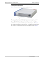
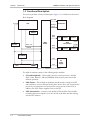
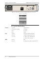
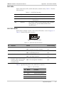
Figure 1-2 shows a 3D view of the ASM-60 standalone modem.
Figure 1-2. 3D View of ASM-60
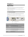
The front panel includes nine LEDs, which display the status of power, data flow,
control signals and provide diagnostics. The front panel also features a 9-pin
D-type (CONTROL DCE) connector for terminal connection for configuration,
control and monitoring. For detailed description of the front panel, see Chapter 3.
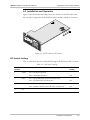
The rear panel includes the AC power connector, a DTE interface connectors and a
line connector. The ASM-60 rear panel is described in greater detail in Chapter 2.
Physical Description
1-3