1
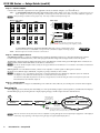
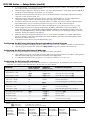
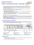
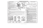
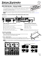
DVS 304 Series — Setup Guide (cont'd)
Step 3 — Connect outputs
Connect video and audio output devices to the applicable connectors marked “Outputs” (see g and h above).
Video — For RGB (RGBHV, RGBS, RGsB) or HD component (R-Y, Y, B-Y) video output connect cables to the BNC's or VGA/DVI-I as shown
below. Outputs are scaled or pass-through RGB ,or scaled component video and can be scaled to more than 60 different output rates.
N RGB pass-through is available on analog outputs only. DVI output is disabled in RGB pass-through mode.
Analog video output
RGBHV
Tip
Ring
Sleeves
Tip
Ring
Left
Right
Left
R
G
/Y
L
R
/R-Y
B
/B-Y
R
G
/Y
B
/B-Y
L
R
/R-Y
Audio output
RGBS
Right
Balanced Stereo Output
H/
HV
V
H/
HV
G
/Y
Tip
Component video (Y, R-Y, B-Y)
RGsB
R
/R-Y
V
B
/B-Y
R
/R-Y
G
/Y
NO GROUND HERE
Sleeves
Tip
B
/B-Y
NO GROUND HERE
Unbalanced Stereo Output
H/
HV
CAUTION
V
H/
HV
For unbalanced audio, connect the sleeve(s) to the center contact
ground. DO NOT connect the sleeve(s) to the negative (-) contacts.
V
For DVI-I (digital and analog) output (DVS 304 DVI models only), connect a suitable display device
to this DVI-I connector for scaled RGB or component video (simultaneous digital and analog outputs).
Audio — Wire the captive screw audio connectors as shown above.
DVI-I
Step 4 — Connect control devices
LAN Ethernet port j — Connect to an Ethernet LAN or WAN via this RJ-45 connector to control the switcher from a remote
location using a PC’s Internet browser, or the control program (the Extron Signal Processing Products Control Program).
The Ethernet connection indicator LEDs indicate the status of the Ethernet connection: the green LED lights when connected to an
Ethernet LAN, and the amber LED flickers as the devices communicate.
N Do not use standard telephone cables, as they do not support Ethernet or Fast Ethernet. Do not stretch or bend cables as transmission
errors could occur.
Remote port k — For serial RS-232 control, connect a host computer or control system via this 9-pin D connector.
RS-232 protocol (default values): 9600 baud, 1 stop bit, no parity, 8 data bits, no flow control.
™
N See chapter 4, “SIS Programming and Control”, in the DVS 304 Series User’s Manual, for definitions of the SIS commands.
See chapter 5, “DVS 304 Series Control Software” to install and use the control software.
Use an RS-232 cable that only utilizes Tx (2), Rx (3), and ground (5) to avoid activating the contact closure feature (refer to the
DVS 304 Series User's Manual, chapter 2).
Step 5 — Connect power
AC power connector a — Plug in a standard IEC power cord from a 100 to 240 VAC, 50 - 60 Hz power source into this receptacle
Powering Up
When applying power to the DVS, the unit undergoes a start-up self testing sequence (see image below), and then the LCD displays
the default display cycle, showing the active input, input signal type, and the output resolution and refresh rate.
Apply
Power
All input LEDs flash
once in sequence
(last active, then 1-4).
5
sec.
Extron
Electronics
2
sec.
DVS 304
DVI AD
2
sec.
60-xxxx-xx
FW ver.
2.00
Key
2
sec.
= flashing
= lit
1
Default Display Cycle
1
sec.
3
1
sec.
Last active input
LED remains lit
(here input 3).
INPUT 4
RGB SCALED
2
sec.
OUTPUT
[email protected]
2 sec.
N The input and output rates shown
in the default display cycle may diffe r,
depending on the acti ve input and type of video signal.
N When in use and not in any menu, the LCD screen defaults to cycling through the current input/output configuration. The displayed
content may vary, depending on the input video signal type (see typical default display above).
2
DVS 304 Series • Setup Guide