1
t
AlphaServer 1000 to AlphaServer 1000A
Model 5/xxx
Upgrade Information
Order Number: EK–AS42X–UP. A01
Digital Equipment Corporation
Maynard, Massachusetts
September 1996
Digital Equipment Corporation makes no representations that the use of its products in the manner described in this
publication will not infringe on existing or future patent rights, nor do the descriptions contained in this publication
imply the granting of licenses to make, use, or sell equipment or software in accordance with the description.
Possession, use, or copying of the software described in this publication is authorized only pursuant to a valid
written license from Digital or an authorized sublicensor.
Copyright Digital Equipment Corporation, 1996. All Rights Reserved.
The following are trademarks of Digital Equipment Corporation:
Alpha AXP, AlphaGeneration, DEC, DECchip, Digital, OpenVMS, and the DIGITAL logo.
Digital UNIX Version 3.0 is an X/Open UNIX 93 branded product.
The following are third party trademarks:
Microsoft is a registered trademark, and Microsoft Windows and Microsoft Windows NT are trademarks of
Microsoft Corporation.
OSF/1 is a trademark of the Open Software Foundation, Inc.
PostScript is a trademark of Adobe Systems, Inc.
All other trademarks and registered trademarks are the property of their respective holders.
S3330
FCC ID: AO9-PB70
FCC NOTICE: This equipment has been tested and found to comply with the limits for a Class B digital device,
pursuant to Part 15 of the FCC rules. These limits are designed to provide reasonable protection against harmful
interference in a residential installation.
Any changes or modifications made to this equipment may void the user's authority to operate this equipment.
This equipment generates, uses, and can radiate radio frequency energy and, if not installed and used in accordance
with the instructions, may cause harmful interference to radio communications. However, there is no guarantee
that interference will not occur to radio or television reception. If this equipment does cause harmful interference to
radio or television reception, which can be determined by turning the equipment off and on, the user is encouraged
to try to correct the interference by one or more of the following measures:
- Reorient or relocate the receiving antenna.
- Increase the separation between the equipment and receiver.
- Connect the equipment into an outlet on a circuit different from that to which the receiver is connected.
- Consult the dealer or an experienced radio/TV technician for help. The user may find the following booklet
prepared by the Federal Communications Commission helpful: How to Identify and Resolve Radio-TV Interference
Problems. This booklet is available from the U.S. Government Printing Office, Washington, DC, 20402. Stock No.
004-00398-5.
All external cables connecting to this basic unit need to be shielded. For cables connecting to option boards, see the
option manual or installation instructions.
This digital apparatus does not exceed the Class B limits for radio noise emissions set out in the radio interference
regulations of the Canadian Department of Communications.
Contents
1 Upgrading Your System
Introduction.......................................................................................................................... 1-1
Special Notices.............................................................................................................. 1-1
Additional Information.................................................................................................. 1-2
Upgrade Kit Inventory.......................................................................................................... 1-2
Preparing the System............................................................................................................ 1-2
Removing Top Cover and Side Panels.................................................................................. 1-3
Removing StorageWorks Hard Disk Drives.......................................................................... 1-5
Removing Option Cards ....................................................................................................... 1-7
Removing the CD-ROM Drive........................................................................................... 1-10
Removing the Memory Modules ........................................................................................ 1-11
Replacing the Top Cover and Side Panel............................................................................ 1-14
2 Updating Configuration Data
Rebuilding EISA Configuration Data ................................................................................... 2-1
Step 1: Start the ECU ................................................................................................... 2-2
Step 2: Step through the ECU dialog boxes. ................................................................. 2-2
Updating the StorageWorks RAID Controller Firmware....................................................... 2-2
Step 1: Create a standalone configuration utility floppy................................................ 2-3
Step 2: Run the utility to set controller parameters. ...................................................... 2-4
Step 3: Update the RAID controller firmware............................................................... 2-5
Verifying Custom Settings/Variables.................................................................................... 2-7
For Windows NT:.......................................................................................................... 2-7
For Digital UNIX and OpenVMS: ................................................................................. 2-7
Building and Boot the Operating System.............................................................................. 2-7
Completing the Upgrade ...................................................................................................... 2-7
AlphaServer 1000 to 1000A Upgrade v
1
Upgrading Your System
Introduction
This guide, intended for self-maintenance customers and Digital service
representatives, describes the procedure for upgrading the AlphaServer 1000 system
to the AlphaServer 1000A Model 5/xxx system. The upgrade is a multi-step
procedure requiring that you remove the system unit enclosure panels, remove
components from the AlphaServer 1000 system and reinstall them in the
AlphaServer 1000A Model 5/xxx system.
Special Notices
In this guide, warning notices provide information to prevent personal injury, and
caution notices emphasize important information that can affect the operation of
your system. Notes are used to provide information of general interest.
Conventions used in entering commands are shown in the table below:
Convention
Meaning
Ctrl/x
Ctrl/x indicates that you hold down the Ctrl key while you press
another key, indicated here by x.
boot
Commands that you enter are shown in this special typeface.
Commands shown in lowercase letters can be entered in either
uppercase or lowercase. Commands shown in uppercase letters
must be entered in uppercase for the command to work.
show config
Console command abbreviations must be entered exactly as
shown.
[]
In command descriptions, brackets indicate optional elements.
{}
In command descriptions, braces containing items separated by
commas indicate mutually exclusive items.
AlphaServer 1000 to 1000A Upgrade 1-1
Upgrading Your System
italic type
Italic type in console command sections indicates a variable.
Additional Information
For additional information, you should consult the AlphaServer 1000 Owner's
Guide, AlphaServer 1000A Owner’s Guide, and AlphaServer 1000A Model 5/xxx
Owner’s Guide Supplement, which contain information on how to start, use,
update, troubleshoot, and configure your system. General system information such
as console commands and system care are also available in the Owner's Guides.
Upgrade Kit Inventory
The AlphaServer 1000 to AlphaServer 1000A Model 5/xxx upgrade kit contains the
following:
•
AlphaServer 1000A Model 5/xxx system enclosure with:
5/xxx CPU module, installed
Diskette drive, installed
Power supply, installed
Wide SCSI StorageWorks shelf, installed
•
External SCSI terminator (50-pin)
•
Return mailing label
•
A variety of operating system related contents is also provided with the
upgrade. The specific contents vary according to operating system.
•
AlphaServer 1000A Owner’s Guide
•
AlphaServer 1000A Model 5/xxx Owner’s Guide Supplement
Preparing the System
To prepare your system for the upgrade:
1. Shut down the operating system following the instructions listed in the
operating system documentation.
2. Set the On/Off switches on all external options connected to the system to the
off position.
3. Set the On/Off switch on the system unit to the off position.
4. Unplug the power cord.
1-2 AlphaServer 1000 to 1000A Upgrade
Upgrading Your System
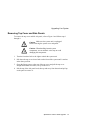
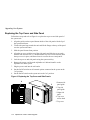
Removing Top Cover and Side Panels
To remove the top cover and left side panel, refer to Figure 1 and follow steps 1
through 4.
Caution: Make sure the system unit is unplugged
before removing the system cover and panels.
Caution: When handling internal system
components, use an antistatic wrist strap to avoid
damaging the components.
1. Turn the front door lock to the right to unlock the system unit.
2. Pull down the top cover release latch on the front of the system until it catches
in the down position.
3. Grasp the finger groove at the rear of the top cover and pull the top cover
straight back about two inches; lift up on the cover.
4. Pull the top of the side panel back, then up and away from the unit and pull up
on the panel to remove it.
AlphaServer 1000 to 1000A Upgrade 1-3
Upgrading Your System
Figure 1 Removing the Top Cover and Side Panels
1
1 Top cover
release
latch
MA00231
1-4 AlphaServer 1000 to 1000A Upgrade
Upgrading Your System
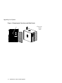
Removing StorageWorks Hard Disk Drives
Remove the StorageWorks drives from your AlphaServer 1000 system by
squeezing the outer mounting tabs while pulling the drive out. Refer to Figure 2.
Install the drives in your AlphaServer 1000A Model 5/xxx system by slowly and
firmly sliding the drive unit in until it “snaps” into place.
If you are maintaining the same storage configuration, install the drives in the same
relative position, that is the top drive in the AlphaServer 1000 becomes the top
drive in the AlphaServer 1000A system.
Install the external SCSI terminator (50-pin) onto the external bulkhead connector.
Refer to Figure 3. The terminator ships in the accessories kit with the AlphaServer
1000A system.
The embedded SCSI controller on the system board:
•
Supports a total of seven drives.
•
Provides 8-bit Fast narrow SCSI-2 support for up to two 5.25 inch internal
removable-media devices and one external bulkhead connector.
•
Provides 16-bit fast-wide SCSI-2 support for internal StorageWorks devices
(narrow devices are also supported).
Refer to the AlphaServer 1000A Owner’s Guide for more information on SCSI bus
configurations.
When configuring the StorageWorks shelf, note the following:
•
Narrow SCSI (8-bit) devices can be used in the wide StorageWorks shelf, as
long as the devices are at a supported revision level. The narrow devices will
run in narrow mode.
•
Narrow and wide devices can be mixed in the wide StorageWorks shelf. In a
mixed configuration, wide devices run in wide mode and narrow devices run in
narrow mode.
•
For best performance, wide devices should be operated in wide SCSI-2 mode
Supported devices and configuration rules for wide SCSI-2 are described in the
Wide SCSI Technical Bulletin. This bulletin is frequently updated and can be
downloaded from the Internet:
Via FTP on ftp.digital.com
—Once connected, go to /pub/Digital/Alpha/systems
Via the World Wide Web at http://www.service.digital.com/alpha/server
AlphaServer 1000 to 1000A Upgrade 1-5
Upgrading Your System
Figure 2 Removing or Installing a StorageWorks Disk Drive
MLO-013583
1-6 AlphaServer 1000 to 1000A Upgrade
Upgrading Your System
Figure 3 Installing the External 50-Pin SCSI Terminator on the Bulkhead
Connector
Optional
SCSI
Ports
SCSI
Terminator
MA00945
Removing Option Cards
Remove EISA, ISA, or PCI option cards from the system board, and install them
on the AlphaServer 1000A system board. Refer to Figure 4. Note that the
AlphaServer 1000A has seven PCI slots and two EISA slots. Figure 5 shows the
AlphaServer 1000A system board.
AlphaServer 1000 to 1000A Upgrade 1-7
Upgrading Your System
Figure 4 Removing or Installing an Option Card
Slot Cover
Screw
Option Card
MA00917
1-8 AlphaServer 1000 to 1000A Upgrade
Upgrading Your System
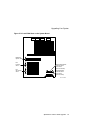
Figure 5 PCI and EISA Slots on the System Board
EISA/ISA
Option Slots
PCI
Primary
Slots
PCI
Secondary
Slots
11
12
13
1
2
3
4
Removable Media
Internal SCSI
Connector
(50-Pin Narrow)
StorageWorks
Internal SCSI
Connector
(68-Pin Wide)
MLO-013584
AlphaServer 1000 to 1000A Upgrade 1-9
Upgrading Your System
Removing/Installing the CD-ROM Drive
Remove the CD-ROM drive and install it in the AlphaServer 1000A 5/xxx system.
Refer to Figure 6.
Figure 6 Removing/Installing CD-ROM Drive
Drive
Bracket
Screws
Data Cable
Power Cable
MLO-013652
1-10 AlphaServer 1000 to 1000A Upgrade
Upgrading Your System
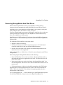
Removing the Memory Modules
Remove memory SIMMs from system (see Figure 7) and install them in the
AlphaServer 1000A 5/xxx system (see Figure 8).
Note that the ECC bank SIMM is not used in 5/xxx systems. The ECC bank is left
unfilled. All AlphaServer 1000A 5/xxx memory bank SIMMs have error detecting
and correcting logic (ECC functionality) built in.
Caution: The ECC SIMM is not compatible with memory bank SIMMs. Do not
place the ECC SIMM in a memory bank of the new AlphaServer 1000A 5/xxx
system. The SIMM in the ECC bank should be left in the AlphaServer 1000 4/2xx
system and returned to Digital.
Be sure to comply with the following memory configuration rules when adding
memory:
•
Bank 0 must contain a memory option (4 SIMMs, 0, 1, 2, and 3)
•
A memory option consists of 4 SIMMs (0, 1, 2, and 3)
•
All SIMMs within a bank must be of the same capacity
AlphaServer 1000 to 1000A Upgrade 1-11
Upgrading Your System
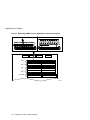
Figure 7 Removing SIMMs from the AlphaServer 1000 System Board
Bank 3
Bank 2
Bank 1
Bank 0
ECC Banks
SIMM 1
SIMM 3
SIMM 0
SIMM 2
SIMM 1
SIMM 3
SIMM 0
SIMM 2
SIMM 1
SIMM 3
SIMM 0
SIMM 2
SIMM 1
SIMM 3
SIMM 0
SIMM 2
ECC SIMM for Bank 2
ECC SIMM for Bank 3
ECC SIMM for Bank 0
ECC SIMM for Bank 1
MA00315
1-12 AlphaServer 1000 to 1000A Upgrade
Upgrading Your System
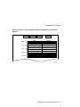
Figure 8 Memory Layout on System Board for AlphaServer 1000A 5/xxx
Systems
Bank 3
Bank 2
Bank 1
Bank 0
SIMM 1
SIMM 3
SIMM 0
SIMM 2
SIMM 1
SIMM 3
SIMM 0
SIMM 2
SIMM 1
SIMM 3
SIMM 0
SIMM 2
SIMM 1
SIMM 3
SIMM 0
SIMM 2
Unused
MLO-013455
AlphaServer 1000 to 1000A Upgrade 1-13
Upgrading Your System
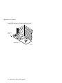
Replacing the Top Cover and Side Panel
Follow these steps and refer to Figure 9 to replace the top cover and side panel of
the system unit:
1. Align the guides on the top and bottom inside of the side panel with the lip of
the system unit frame.
2. Tilt the side panel top towards the unit and lift the flange at the top of the panel
over the system unit frame.
3. Slide the panel forward into position.
4. Align the top cover with the top of the side panels and slide the cover gently
onto the unit from the rear (5). Hold down the top cover release latch (4) until
the top cover is in place, and then release it to secure the cover and panels.
5. Lock the top cover and side panels using the system unit key.
6. Remove the power cord from the AlphaServer 1000 and install it on the
AlphaServer 1000A system.
7. Plug the power cord into the wall outlet.
8. Set the On/Off switches on all external options connected to the system to the
"on" position.
9. Set the On/Off switch on the system unit to the "on" position.
Figure 9 Replacing the Top Cover and Side Panels
4
5
3
1 Bottom side
panel guide
2 Top side
panel guide
2
3 Right side
panel
4 Top cover
release latch
1
5 Top cover
MA00281
1-14 AlphaServer 1000 to 1000A Upgrade
2
Updating Configuration Data
This chapter explains how to update the configuration information in the EISA
Configuration Utility, build and boot the operating systems, and how to verify custom
settings/variables. If your system is configured with a StorageWorks RAID controller
below V3.11, it is strongly recommended that you also update the RAID controller
firmware, as described in this chapter.
Rebuilding EISA Configuration Data
If the AlphaBIOS console firmware detects an error in the configuration, it will prompt
you to accept the default configuration. It will also prompt you if the EISA Configuration
Utility (ECU) needs to be run.
Use the EISA Configuration Utility diskette, V1.9, to rebuild your EISA configuration
data. Revisions below V1.9 will not work with AlphaServer 1000/1000A 5/xxx CPU
modules. It is recommended that you run the ECU from the graphics monitor.
_________________________ Caution ___________________________
There are two variants of the ECU, one for OpenVMS and Digital UNIX and
another for Windows NT. Be sure to use the appropriate ECU diskette for your
operating system.
____________________________________________________________
AlphaServer 1000 to 1000A Upgrade 2-1
Upgrading Your System
Step 1: Start the ECU
Insert the ECU diskette in the drive. If the system powers up to the SRM console prompt,
>>>, enter the ecu or arc command. The AlphaBIOS firmware will load.
When the AlphaBIOS firmware is loaded, and informational screen displays telling you
that you need to fix your configuration data. Then the AlphaBIOS boot screen is
displayed.
Choose the AlphaBIOS Utility menu. From the Utility menu, select Run ECU from floppy.
Step 2: Step through the ECU dialog boxes.
The ECU displays a few dialog boxes. When these begin to appear do the following:
A. At the Main Menu dialog box, press <Enter>.
B. If an ID mismatch dialog box is displayed, press <Enter> and wait about 30
seconds.
C. At the Main Menu dialog box, select STEP 5: Save and Exit, and press
<Enter>.
D. Press <Enter> to save the configuration.
E. Press <Enter> again to reboot the AlphaBIOS console. The AlphaBIOS firmware
will reboot and display the Boot screen.
If your system is configured with a StorageWorks RAID controller, continue with the
following section of this chapter. If you do not have a RAID controller, skip the following
section.
Updating the StorageWorks RAID Controller Firmware
If your system is configured with a StorageWorks RAID controller with a firmware
version below V3.11, it is strongly recommended that you update the RAID controller
firmware.
Although the utility can be executed from CD-ROM, the RAID configurations cannot be
saved to CD-ROM. It is recommended that you create a utility floppy, as described in
Step 1, below. For complete instructions on using the RAID standalone configuration
utility, refer to the StorageWorks RAID Array 200 Subsystems Family Controller
Installation and Standalone Configuration Utility User’s Guide.
2-2 AlphaServer 1000 to 1000A Upgrade
Upgrading Your System
_________________________ Caution ___________________________
Using a version of the RAID firmware below V3.11 will render your RAID
controller inoperable.
Before updating the RAID firmware, do a backup of the existing configuration
for each RAID controller.
____________________________________________________________
Step 1: Create a standalone configuration utility floppy.
__________________________ Note_____________________________
Systems running Digital UNIX or OpenVMS will need to create a utility floppy
(steps A, B, and C) on a PC equipped with a CD-ROM drive.
____________________________________________________________
A. Insert the RAID Utility CD-ROM into the CD-ROM drive.
B. Insert a diskette into the diskette drive.
C. At the DOS prompt, copy the RAID Standalone Configuration Utility for Alpha
Systems from the CD-ROM onto the diskette drive.
c:> copy e:\utility\swxcrmgr\*.* a:
AlphaServer 1000 to 1000A Upgrade 2-3
Upgrading Your System
Step 2: Run the utility to set controller parameters.
A. On the AlphaServer system, load the AlphaBIOS firmware.
On systems configured for Windows NT, select the Utilities Menu.
On systems configured for Digital UNIX or OpenVMS, enter the arc command
at the console prompt.
B. From the Utilities Menu, select Run Maintenance Program.
C. In the Run Maintenance Program dialog box, enter the name of the program you are
running from the floppy you created:
a:swxcrmgr
Or, if you are running the utility from the CD-ROM, use <Tab> to enter the location
list box and select the CD-ROM drive:
cd:\utility\swxcrmgr\swxcrmgr.exe
Note that if you run the utility from the CD-ROM, you cannot save the configuration.
__________________________ Note _____________________________
If you are installing a new controller or if the drives on the controller are marked
as failed, enter a:swxcrmgr -o from the floppy or
cd:\utility\swxcrmgr\swxcrmgr.exe -o from the CD-ROM.
____________________________________________________________
D. From the Main menu, select Controller Setup. The Edit/View Parameters
menu is displayed. Use the arrow keys to step through the menu items. Set the
Hardware Parameters and Data Parameters as shown in the table below. Set the SCSI
Xfr Parameters and Startup Parameters using the values you previously recorded for
these parameters.
Hardware Parameters
Battery-Backup
Disabled (enabled if you have battery backup)
StorageWorks Fault Management
Enabled
Data Parameters
Default rebuild rate
50
Stripe size (K bytes)
8
Controller read ahead
Disabled
2-4 AlphaServer 1000 to 1000A Upgrade
Upgrading Your System
E. After you have set the controller parameters, press the Esc key. At the Save
altered controller configuration? prompt, select Yes to save the
parameters you have set. Note that if you ran the utility from the CD-ROM, you
cannot save the parameters.
F. Exit from the utility. You will be returned to the ARC firmware Boot menu. You are
ready to update the RAID controller firmware, as described next.
Step 3: Update the RAID controller firmware.
A. From the Boot menu, select Run a Program. If you are running the utility from
the floppy, enter the following at the Program to Run: prompt:
a:swxcrfw filename.xxx
Or, if you are running the utility from the CD-ROM, enter:
cd:\utility\swxcrmgr\swxcrfw filename.xxx
Filename.xxx is the firmware filename, and xxx is the firmware version you want to
load. For multiple controllers, update EISA firmware files first, followed by PCI files.
Review the following examples.
Filename for Single EISA Controller
swxcrfw swxcrfwa.216
Filename for Single PCI Controller
swxcrfw swxcrfwp.219
Filenames for Multiple Controllers
swxcrfw swxcrfwa.216 swxcrfwa.216 swxcrfwp.219
The system displays a series of messages. The final message asks you to cycle the
system power. Press the Reset button.
AlphaServer 1000 to 1000A Upgrade 2-5
Upgrading Your System
B. Enter a:swxcrmgr from the floppy (or cd:\utility\swxcrmgr from the CDROM) to start the standalone configuration utility, and view the firmware version
displayed on the Main menu to verify the update.
•
For a PCI controller, exit the utility and remove the standalone utility diskette
from the drive. This completes the firmware update for PCI.
•
For an EISA controller that was V1.99 or earlier before the update, select the
appropriate new .CFG file for your controller and copy it to the ECU diskette.
The table that follows identifies the .CFG files.
.CFG Files
!MLX0077.CFG
1-channel controller running Windows NT
!MLX0075.CFG
3-channel controller running Windows NT
AMLX0077.CFG
1-channel controller running Digital UNIX or OpenVMS
AMLX0075.CFG
3-channel controller running Digital UNIX or OpenVMS
C. Run the ECU again to load the new CFG file.
__________________________ Note _____________________________
If you are not able to copy the .CFG file to your ECU diskette, do the following:
1. Run the ECU and delete the board.
2. Remove the ECU diskette and insert the standalone utility diskette.
3. At the Add Configuration (CFG) file menu, select the appropriate choice and
press Enter.
4. At the Destination Diskette prompt, remove the standalone utility
diskette and insert the ECU diskette, making sure it is write-enabled, then press
Enter.
5. At the confirmation prompt, press Enter, and at the highlighted slot, press
Enter again. The board will now appear on the display.
6. When you have finished adding boards, press F10 to exit.
____________________________________________________________
2-6 AlphaServer 1000 to 1000A Upgrade
Upgrading Your System
Verifying Custom Settings/Variables
For Windows NT:
Using the cursor control keys:
A. Select the CMOS Setup menu to check and set system settings.
B. From the CMOS Setup Menu, press F6 to enter advanced CMOS setup mode. There
are additional system setting in the advanced mode.
Refer to the AlphaServer 1000/1000A Model 5/xxx Owner’s Guide Supplement for
more information.
For Digital UNIX and OpenVMS:
Use the show and set commands at the SRM console prompt, >>>, to display and
reset the values of the following environment variable settings. Refer to the service or
owner’s guide for your system for details.
auto_action
ewa0_mode
os_type
boot_def_dev
boot_file
boot os_flags
bus_probe_algorithm (should be set to New)
Building and Boot the Operating System
Digital UNIX systems: You will need to rebuild the kernel. For instructions, refer to the
Digital UNIX Release Notes and Installation Instructions, as appropriate for your system.
After you rebuild the kernel, you can boot the operating system.
OpenVMS and Windows systems. You have completed the upgrade and can boot the
operating system.
Completing the Upgrade
To complete the upgrade, verify that the CPU is installed correctly by checking the
operator control panel display: When the systems is turned on and the power up process is
completed, the operator control panel should display the message “Model 5/xxx,” where
“xxx” is the CPU speed.
Future reference, write the number of the performance-enhanced CPU upgrade option on
the conversion label included in the upgrade kit:
AlphaServer 1000 to 1000A Upgrade 2-7
Upgrading Your System
Attach the label to the rear of the system.
To return the AlphaServer 1000 system to Digital, pack it in the box that contained your
new system. Locate the return label in the upgrade kit, and return the system to Digital
Equipment Corporation.
2-8 AlphaServer 1000 to 1000A Upgrade