1
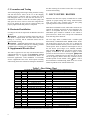
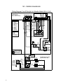
VI. ELECTRICAL SERVICE Note – Always refer to the inside of the electrical box cover for the correct wiring diagram, and always refer to the nameplate on the exterior of the cabinet for the correct electrical specifications. WARNING – ELECTRICAL SHOCK CAN CAUSE PERSONAL INJURY OR DEATH. Disconnect all power supplies before installing or servicing electrical devices. Only trained and qualified personnel should install, repair or service this equipment. WARNING – THE UNIT MUST BE PROPERLY GROUNDED! The main electrical service must be protected by a fuse or circuit breaker and be capable of providing the amperes required by the unit at nameplate voltage. All wiring must comply with the national electrical code and/or any local codes that may apply. Access to the line voltage connection is through the knockouts provided on the side next to the front. Route EMT or flexible conduit with appropriate size and type of wire. CAUTION – Route field wiring to avoid contact with electrically live bare metal parts inside the electrical box. CAUTION – Disconnect power from the unit before removing or replacing any connectors, or servicing the blower motor. CAUTION – When servicing an ECM blower motor, disconnect power and wait at least 5 minutes before opening the motor to avoid electric shock from the motor’s internal capacitors. CAUTION – Units with internal installed Supplemental Electric Heat require a separate power supply for the Supplemental Electric Heat. VII. 24 VOLT CONTROL CIRCUIT Note – Always refer to the inside of the electrical box cover for the correct wiring diagram. Important – All 24V control wiring should be 18 gage minimum. There are two basic sections of the low voltage circuit; transformer and internal controls. A. Transformer An internal transformer provides 24Vac for all control features of the AHU, the room thermostat, the Split System Controller in the CU, and the Y2 power to the CU. The transformer is larger than the industry standard, but it is in a warm electrical box and can be overloaded quickly. Transformer Usage (VA) Component Room Thermostat Blower Motor Control Split System Controller Y2 Output to CU Electric Heat Relay (2) Total Transformer VA size VA 1 2 2 4 12 21 55 Important – If the system’s external controls require more than shown in table 5, an external transformer and isolation relays should be used. Important – Miswiring of 24Vac control voltage on system controls can result in transformer burnout. Important – Units with a dual voltage rating (example, 208/230) are factory-wired for the higher voltage (example, 230). If connected to a power supply having the lower voltage, change the wiring to the transformer primary to the correct lead; otherwise premature failure, or inability to operate the control components may occur. B. Internal Controls The internal controls perform the following functions: 1) ECM Blower Motor Control 2) Supplemental Electric Heat for 2nd Stage Heat. 1. ECM Blower Operation (-xxV) When 24Vac is applied to the G terminal on the AHU wiring block, the ECM blower motor will run at Low speed. When 24Vac is applied to both the G and the Y terminals on the fan coil wiring block for 1st stage operation, the ECM blower motor will run at Medium speed. When 24Vac is applied to both the G and the Y2 terminals for 2nd stage operation, the ECM blower will run at Medium-High speed. The ECM blower will run at High speed when 24Vac is applied to either the W or the E terminal. CFM outputs for the ECM blower are factory set and should not be changed in the field other than the Adjust setting, which allows the blower to operate at +/-10% of the factory setting. For example, if the Adjust tap is set to the “-“, all the speeds will operate at 90% of the factory setting. If the Adjust tap is set to the “+”, all the speeds will operate at 110% of the factory setting. The Adjust tap is the only tap on the Blower Speed Controller that should ever be moved from the factory setting. Important – Power to the unit must be reset before the new settings are enabled. The blower motor also provides internal circuitry that will try to maintain the setpoint CFM when changes occur in the external static pressure, such as the filter getting dirty over time. The motor does this by increasing its torque output to compensate. Important – The ECM motor is Factory programmed with delay profiles for start and stop to ensure the blower motor slowly ramps up to the proper CFM output and backs 7