1
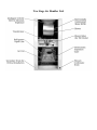
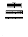
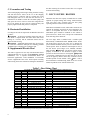
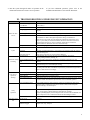
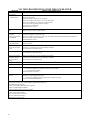
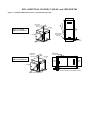
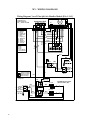
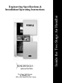
Inside the Two Stage Air Handler Engineering Specifications & Installation/Operating Instructions Two Stage Split System Air Handler Unit FS3-x-2xV thru FS5-x-2xV Series Two Stage Air Handler Unit TABLE OF CONTENTS Section Title Page I. Introduction to ECONAR Heat Pumps 2 II. Applications 3 III. Available Models Capacity Ratings, Configuration Options, Physical Data, Electrical Data, Blower Performance Data 3 IV. Unit Location / Installation A. Air Handler Unit B. Refrigeration Line Set Installation C. Evacuation and Testing D. Horizontal Installation E. Supplemental Electric Heat 5 V. Duct System / Blower 6 VI. Electrical Service 7 VII. 24 Volt Control Circuit A. Transformer B. Internal Controls 7 VIII. Startup / Checkout 8 IX. Service 9 X. Room Thermostat Operation 9 XI. Troubleshooting Guide for Unit Operation 10 XII. Troubleshooting Guide for ECM Blower 11 XIII. Additional Figures, Tables, and Appendices 12 XIV. Wiring Diagrams 13 I. INTRODUCTION TO ECONAR HEAT PUMPS WARNING – Service of refrigerant-based equipment can Enertech Global, LLC, is home to ECONAR geothermal heat pumps, a brand that has been in Minnesota for more than twenty years. The cold winter climate has driven the design of ECONAR heating and cooling equipment to what is known as a "ColdClimate" geothermal heat pump. This cold climate technology focuses on maximizing the energy savings available in heating dominated regions without sacrificing comfort. Extremely efficient heating, cooling, dehumidification and optional domestic hot water heating are provided in one neatly packaged system. WARNING – INJURY OR DEATH CAN RESULT Enertech produces three types of ECONAR heat pumps: hydronic, which transfers energy from water to water; forced air, which transfers energy from water to air; and combination, which incorporates the hydronic heating unit into a forced air unit. Geothermal heat pumps get their name from the transfer of energy to and from the ground. The ground-coupled heat exchanger (geothermal loop) supplies the source energy for heating and absorbs the discharged energy from cooling. The system uses a compression cycle, much like your refrigerator, to collect the ground's energy supplied by the sun and uses it to heat your home. Since the process only moves energy, and does not create it, the efficiencies are three to four times higher than most efficient fossil fuel systems. Safety and comfort are designed into every ECONAR geothermal heat pump. Since the system runs completely on electrical energy, the entire home can have the safety of being gas-free. The best engineering and quality control is in every heat pump. Proper application and correct installation will ensure excellent performance and customer satisfaction. The Enertech commitment to quality is written on the side of every ECONAR heat pump built. Throughout the manufacturing process, the technicians who assemble each unit sign their names to the quality assurance label after completing their inspections. As a final quality test, every unit goes through a full run-test where the performance and operation is verified in both the heating and cooling modes. No other manufacturer goes as far as to run a full performance check to ensure system quality. This guide discusses the ECONAR Two Stage Air Handler Unit for use with a Two Stage Compressor Unit on Two Stage Split System geothermal heat pump applications. The pre-charged system uses R-410A, an environmentally friendly refrigerant; and has factory-installed internal Thermostatic Expansion Valves. 2 be hazardous due to elevated system pressures and hazardous voltages. Only trained and qualified personnel should install, repair or service. The installer is responsible to ensure that all local electrical, plumbing, heating and air conditioning codes are followed. FROM EXPLOSION WHEN OXYGEN IS USED TO PURGE A REFRIGERANT SYSTEM. Never use air or oxygen to purge or pressure test the refrigerant system. Oxygen reacts violently with oil, and mixtures of air and R410A may be combustible at pressures above 1 atmosphere. WARNING – ELECTRICAL SHOCK CAN CAUSE PERSONAL INJURY OR DEATH. Disconnect all power supplies before installing or servicing electrical devices. Only trained and qualified personnel should install, repair or service this equipment. CAUTION –Verify refrigerant type before servicing. The nameplate on the heat pump identifies the type and the amount of refrigerant. All refrigerant removed from these units must be reclaimed by following accepted industry and agency procedures. CAUTION – R410A refrigerant requires extra precaution when service work is being performed. Invasion into the refrigerant system must be a last resort. Ensure all other diagnosis and methods have been used before attaching refrigerant instruments and before opening the refrigerant system. Synthetic oil (POE) is extremely hydroscopic, meaning it has a strong chemical attraction to moisture. Brief exposure to ambient air could cause POE to absorb enough moisture that a typical vacuum may not remove. Note – Performance values are +/-10% and are subject to change without notice. COMMON ACRONYMS ACU Air Coil Unit AHU Air Handler Unit CFM Cubic Feet per Minute CU Compressor Unit ECM Electronically Commutated Motor FPT Female Pipe Thread MPT Male Pipe Thread II. APPLICATIONS ECONAR Split System geothermal heat pumps consist of an Air Handler Unit (AHU) and a fully-charged Compressor Unit (CU) to offer an extremely efficient and safe way of providing the primary space heating and all the cooling for many applications (see Figure 1). III. AVAILABLE MODELS Capacity Ratings Air Flow Ratings Capacity (CFM, Typical) (Tons, Typical) 910 -FS3-x-2xV 1180 3 1295 -FS4-x-2xV 1680 4 1425 -FS5-x-2xV 1850 5 *Note: CFM should be as specified plus up to 10%. Model Configuration Options – Air Handler Unit Model Suffix FSx-1-2OV FSx-1-2EV Description Standard, 208/230-1, 60Hz with 2-Stage Variable Speed ECM Blower Motor 208/230-1, 60Hz with 2-Stage Variable Speed ECM Blower Motor and 10kW/240V Slide-In Heater Physical Dimensions J B A I Access Panels Electrical Knockouts Electrical Knockouts Secondary Drains, ¾” FPT H Refrigerant Vapor Line Primary Drain, ¾” MPT Refrigerant Liquid Line F D Model FS3 - 5 Cabinet Dimensions H W D 46.1 25.3 26.1 Blower Opening A B 12.0 C E W 10.3 Cond. Drain C E 3/4” MPT(1) 2.5 15.0 G Other Dimensions F G I 5.1 16.0 6.3 J 3.2 Refrig Connection Liquid Vapor 3/8 OD 7/8 OD Note: Air filter and filter rack are required to be provided at installation. (1) Note: Primary Condensate Drain is MPT, and Secondary Drains are 3/4” FPT. 3 Physical Data Description FS3 or 4 FS5 4-ton 5-ton Expansion Device – Thermostatic 4.44 Ft2, 15fpi Air Coil Type – High Density A-Coil 4 Rows Quantity of Air Coil Rows ECM Fan Motor Type 3/4 Fan Motor (HP) 10x8 Fan Wheel (dia. x width) – ECM Motor 55 Transformer (VA) 230 Unit Weight (lbs)* Note: Unit weight includes pallet and packing materials. Electrical Data (all HCAR-type circuit breaker per NEC) Voltage Total Min. Max Model Frequency (Hz) Phase HP Blower FLA LRA FLA Amp. Fuse FS3-5 208/230-1, 60 3/4 6.8 -- 6.8 8.5 15 Note: Electrical data does not include power for a Supplemental Electric Heater. This heater requires a separate power supply to be provided to the AHU. Air Handler Unit Blower Performance Data Model FS3-1-2xV FS4-1-2xV FS5-1-2xV 4 Low (G) 520 740 815 Medium (Y) 910 1295 1425 Medium-High (Y2) 1180 1680 1850 High (W2, E) 1300 1800 1920 IV. UNIT LOCATION / INSTALLATION Inspect for shipping damage immediately at delivery, and file claims immediately with the shipping company. Check to ensure that units have correct model numbers, electrical ratings, and accessories that match the original order. CAUTION – Units must be kept in an upright position during transportation or installation, or severe internal damage may occur. Important – To ensure easy removal and replacement of access panels, leave panels secured in place until the unit is set in place and leveled. Important – Locate the unit in an indoor area where the ambient temperature will remain between 45oF and 104oF. Service is done primarily from the front. Top and rear access is desirable and should be provided when possible. CAUTION – Do not use this unit during construction. Dust and debris may quickly contaminate electrical and mechanical components; resulting in damage. CAUTION – Before driving screws into the cabinet, check on the inside of the unit to ensure the screw will not damage electrical, water, or refrigeration lines. The Installation Process is made up of these Steps: 1. Confirm sufficient air flow. 2. Confirm sufficient electrical service. 3. Install the Air Handler Unit; keeping the A-Coil sealed until braze connections will be made. 4. Install the Refrigerant Line Set; keeping it sealed until braze connections will be made. Protect the cabinet panel finish during brazing, and slide the grommets temporarily away from the brazing area. 5. Open the braze connections, and braze the Refrigerant Line Set to the CU and to the AHU. 6. Properly evacuate the Refrigerant Line Set and A-coil. 7. Properly open the Service Valves on the CU and ensure the seal caps are fully restored and properly tightened (finger tight plus 1/12th turn (1/2 hex flat)). 8. Re-check all braze connections for leaks. 9. Complete operational checkout. A. Air Handler Unit Installation Install the AHU for Split System applications. Note – The AHU has an internal Thermostatic Expansion Valve with integrated check valve sized for the A-Coil. Check the air coil for cleanliness and clean if needed. Note Remove any shipping material (if provided) that supported the blower assembly Note – The A-coil is factory-sealed with a small holding charge of nitrogen. Prior to brazing the refrigerant line set, cut off the ends to release the holding charge. Important – The AHU condensate pan is a combination vertical/horizontal pan with double drains that require fieldinstalled externally vented traps. The primary drain is 3/4” MPT, and the secondary drains are 3/4” FPT (FPT are plugged). To use a secondary drain in addition with the primary drain, remove the corresponding knockout on the front of the cabinet and the corresponding plastic plug. Important – Close/plug any unused drain openings. Unit Cabinet Air Vent 6" drop minimum 3" Rise The condensate line leaving the U bend of the condensate trap must be at least 3” below the base of the unit. This requires the U bend to be 6” below the unit to give the upward portion of the U bend a 3” rise. The condensate trap should be vented after the U bend to break the negative pressure in the air chamber and allow the condensate to flow. The unit must be level, and the condensate line should be pitched away from the unit a minimum of 1/8” per foot. If the unit produces an odor in the cooling mode, the condensate trap or line may be plugged, or the unit may not be pitched correctly. A small amount of bleach may be poured down the condensate drain in the heat pump to kill any bacterial growth. CAUTION – The AHU requires a field-installed filter and filter rack. Ensure the pressure drop of the air filter is less than 0.1 inch of water column at the specified CFM. B. Refrigeration Line Set Installation Use ACR or L copper tubing and fittings, ensure cutoff burrs are removed from the line openings, and blow out the lines with dry nitrogen before making connections. CAUTION – Insulation on the line set must be suitable for heat pump application, R410A refrigerant, and be at least 1/2” thick (Under certain heating-mode conditions, the refrigerant in the vapor line may approach 200◦F.) Never reuse a refrigerant line set. If the line set is kinked or distorted and can’t be formed back to its original shape, replace the damaged portion. A deformation is defined as 10% of the cross section being restricted and will affect performance. When passing line sets through a wall, seal the opening with silicon-based caulk. Important – Both the vapor line and the liquid line must be isolated from direct contact with water pipes, duct work, floor joists, wall studs or other structural components that could transmit vibration and noise to the living space. Use hanger straps with isolation sleeves to suspend refrigerant tubing from joists. Important – All brazing must be performed using nitrogen circulating at 2-3 psig to prevent oxidation inside the tubing. Use Silflo 15, or equivalent, for the braze material. Always use wet rags to protect Service Valves, and use shielding to protect the finish on cabinets. 5 and then restoring the electrical control box to its original location and mounting. C. Evacuation and Testing After initial purging with nitrogen during and after brazing, and with the Service Valves on the CU in the shipping position (closed = clockwise, full in), evacuate the A-Coil and Refrigerant Line Set to less than 200 microns for a minimum of 20 minutes. Isolate the evacuation pump, and fully open the service valves to release the refrigerant into the A-Coil. Ensure all valve caps are restored securely and properly tightened after this process is completed. D. Horizontal Installation Use hangers and rods to suspend the Air Handler Unit off of a surface. CAUTION – A full-sized secondary drain plan with its own drain is required under the entire AHU when water leakage is a concern, and all condensate drains must be protected from freezing. CAUTION – Additional splash guards may be necessary to extend the condensate drain pan for returning potential condensate blow-off back to the condensate pan. E. Supplemental Electric Heat The AHU is approved for use only with ECONAR electric supplemental heat for use only on top discharge vertical installations. Use a separate duct-installed heater for horizontal applications. Field installation of ECONAR electric supplemental heat in the field requires loosening and lowering the electric control box during this installation V. DUCT SYSTEM / BLOWER Ductwork must have the capacity to handle the air volume required for proper heating and cooling. Undersized duct work will cause noisy operation and poor heat pump operating efficiencies due to lack of airflow. Metal ductwork should be used, and flexible connectors are required for discharge and return air duct connections. See Table 3 for acceptable duct sizes. A duct installed in an uninsulated space should be insulated on the outside to prevent heat loss, absorb noise, and prevent condensation from collecting on the ductwork. The Two Stage AHU is standard with a variable speed Electronically Commutated Motor (ECM) blower motor. The ECM motor converts 230 Volts AC to internal DC power and then modulates the DC power to run the motor at various speeds. There are different CFM outputs in each of the four blower speed ranges (Low, Medium, MediumHigh, or High). Important – The blower will not operate properly if ductwork is not attached to supply a static pressure for the blower motor to work against. Important – The blower compartment access door must be on for the unit to run properly. Blower motors may overheat if run for extended periods of time without a load. Note – refer to the ECM Motor Troubleshooting Guide at the rear of this manual if problems occur with the ECM motor. Table 3 - Duct Sizing Chart CFM 50 75 100 150 200 250 300 350 400 450 500 600 800 1000 1200 1400 1600 1800 2000 2200 2400 Acceptable Branch Duct Sizes Round Rectangular 4” 4x4 5” 4x5, 4x6 6” 4x8, 4x6 7” 4x10, 5x8, 6x6 8” 5x10, 6x8, 4x14, 7x7 9” 6x10, 8x8, 4x16 10” 6x14, 8x10, 7x12 10” 6x20, 6x16, 9x10 12” 6x18, 10x10, 9x12 12” 6x20, 8x14, 9x12, 10x11 Acceptable Main or Trunk Duct Sizes Round Rectangular 10” 10” 10” 12” 12” 14” 16” 16” 18” 20” 20” 22” 22” 4x20, 7x10, 6x12, 8x9 5x20, 6x16, 9x10, 8x12 10x10, 6x18, 8x12, 7x14 6x20, 7x18, 8x16, 10x12 8x18, 9x15, 10x14, 12x12 10x18, 12x14, 8x24 10x20, 12x18, 14x15 10x25, 12x20, 14x18, 15x16 10x30, 15x18, 14x20 10x35, 15x20, 16x19, 12x30, 14x25 10x40, 12x30, 15x25, 18x20 10x40, 15x25, 20x20 12x40, 16x25, 20x20 Tables calculated for 0.05 to 0.10 inches of water friction per 100’ of duct. At these duct design conditions, along with the pressure drop through the filter, the total design external static pressure is 0.20 inches of water. 6 VI. ELECTRICAL SERVICE Note – Always refer to the inside of the electrical box cover for the correct wiring diagram, and always refer to the nameplate on the exterior of the cabinet for the correct electrical specifications. WARNING – ELECTRICAL SHOCK CAN CAUSE PERSONAL INJURY OR DEATH. Disconnect all power supplies before installing or servicing electrical devices. Only trained and qualified personnel should install, repair or service this equipment. WARNING – THE UNIT MUST BE PROPERLY GROUNDED! The main electrical service must be protected by a fuse or circuit breaker and be capable of providing the amperes required by the unit at nameplate voltage. All wiring must comply with the national electrical code and/or any local codes that may apply. Access to the line voltage connection is through the knockouts provided on the side next to the front. Route EMT or flexible conduit with appropriate size and type of wire. CAUTION – Route field wiring to avoid contact with electrically live bare metal parts inside the electrical box. CAUTION – Disconnect power from the unit before removing or replacing any connectors, or servicing the blower motor. CAUTION – When servicing an ECM blower motor, disconnect power and wait at least 5 minutes before opening the motor to avoid electric shock from the motor’s internal capacitors. CAUTION – Units with internal installed Supplemental Electric Heat require a separate power supply for the Supplemental Electric Heat. VII. 24 VOLT CONTROL CIRCUIT Note – Always refer to the inside of the electrical box cover for the correct wiring diagram. Important – All 24V control wiring should be 18 gage minimum. There are two basic sections of the low voltage circuit; transformer and internal controls. A. Transformer An internal transformer provides 24Vac for all control features of the AHU, the room thermostat, the Split System Controller in the CU, and the Y2 power to the CU. The transformer is larger than the industry standard, but it is in a warm electrical box and can be overloaded quickly. Transformer Usage (VA) Component Room Thermostat Blower Motor Control Split System Controller Y2 Output to CU Electric Heat Relay (2) Total Transformer VA size VA 1 2 2 4 12 21 55 Important – If the system’s external controls require more than shown in table 5, an external transformer and isolation relays should be used. Important – Miswiring of 24Vac control voltage on system controls can result in transformer burnout. Important – Units with a dual voltage rating (example, 208/230) are factory-wired for the higher voltage (example, 230). If connected to a power supply having the lower voltage, change the wiring to the transformer primary to the correct lead; otherwise premature failure, or inability to operate the control components may occur. B. Internal Controls The internal controls perform the following functions: 1) ECM Blower Motor Control 2) Supplemental Electric Heat for 2nd Stage Heat. 1. ECM Blower Operation (-xxV) When 24Vac is applied to the G terminal on the AHU wiring block, the ECM blower motor will run at Low speed. When 24Vac is applied to both the G and the Y terminals on the fan coil wiring block for 1st stage operation, the ECM blower motor will run at Medium speed. When 24Vac is applied to both the G and the Y2 terminals for 2nd stage operation, the ECM blower will run at Medium-High speed. The ECM blower will run at High speed when 24Vac is applied to either the W or the E terminal. CFM outputs for the ECM blower are factory set and should not be changed in the field other than the Adjust setting, which allows the blower to operate at +/-10% of the factory setting. For example, if the Adjust tap is set to the “-“, all the speeds will operate at 90% of the factory setting. If the Adjust tap is set to the “+”, all the speeds will operate at 110% of the factory setting. The Adjust tap is the only tap on the Blower Speed Controller that should ever be moved from the factory setting. Important – Power to the unit must be reset before the new settings are enabled. The blower motor also provides internal circuitry that will try to maintain the setpoint CFM when changes occur in the external static pressure, such as the filter getting dirty over time. The motor does this by increasing its torque output to compensate. Important – The ECM motor is Factory programmed with delay profiles for start and stop to ensure the blower motor slowly ramps up to the proper CFM output and backs 7 down after the run time is complete. Ramping of the ECM motor allows for quieter operation and increased comfort. It may take a few seconds for the blower to start when the thermostat initially calls for heating or cooling, and for the blower to stop after the thermostat is satisfied. 2. Supplemental Electric Heat for 2nd Stage 24Vac applied to the W terminal on the wiring block of an AHU equipped with Supplemental Electric Heat will energize an electric heat contactor to power a 5kW heat element of supplemental electric heat. 24Vac applied to the E terminal on the wiring block of an AHU equipped with Supplemental Electric Heat will energize both electric heat contactors to power 10kW of supplemental electric heat. If the application requires 10kW of supplemental electric heat, jumper the W and E terminals on the AHU thermostat wiring block. filter and the air coil. Consider setting up regular service checkups with your Enertech dealer. A. Air Filter The air filter should normally be replaced once a month during normal usage. During extreme usage, or if system performance has decreased, the filter should be replaced more often. A washable electrostatic air filter can be cleaned by spraying water through the filter in the direction opposite to the indicated airflow. This can be done in a garage with a garden hose, or in a large sink. Soap may also be used to provide extra cleaning. Light dirt may be vacuumed off. A dirty filter will increase static pressure to the system and cause the variable speed ECM blower motor to increase speed to maintain airflow levels; and in extreme cases, the blower will not be able produce the correct amount of airflow. These system changes will cause higher airflow noise, more power consumption, and reduced heating or cooling capacity. B. Preseason Inspection VIII. STARTUP / CHECKOUT Before applying power, check the following items: - All construction dust has been cleaned up and all sheetrocking is completed. Construction dust, especially sheetrock dust, can plug the air coil and block airflow. Ensure the air coil and air filter are clean before starting the unit. - Low voltage wiring and any additional control wiring is complete. Set the room thermostat to the “OFF” position. - All high voltage wiring is correct including fuses, breakers, and wire sizes. You may now apply power to the unit. - Place the thermostat in the “FAN ON” position. The blower should start. Check airflow at the registers to make sure that they are open and that air is being distributed throughout the house. When airflow has been checked, move the thermostat to the “FAN AUTO” position. The blower should stop. The following steps will ensure your system is operating properly. - Turn the room thermostat up to its highest temperature setting. Place the thermostat to the "HEAT" position. The blower will start. - Next, turn the thermostat down to its lowest setting. Place the room thermostat in the "COOL" position. The blower will start. - Set the room thermostat for normal operation. - Instruct the owner on correct operation of the room thermostat and fan coil. The unit is now operational. IX. SERVICE Properly installed, the ECONAR Air Handler Unit requires only minor maintenance, such as periodic cleaning of the air 8 Before each season, the air coil, drain pan, and condensate drain should be inspected and cleaned as follows: - Turn off circuit breakers. - Remove access panels. - Clean air coil by vacuuming with a soft-brush attachment. - Remove any foreign matter from the drain pan. - Flush pan and drain tube with clear water. - Replace access panels and return power to the unit. CAUTION – Servicing systems using R410A refrigerant requires special consideration (Refer to ECONAR Instruction 10-2016 for more detail.). Always install a new filter/dryer after replacing a refrigeration component (compressor, etc.) and evacuate down to 150 microns. C. Thermostatic Expansion Valve Important – The TEV has an internal check valve to control refrigerant in one direction and bypass refrigerant in the opposite direction. A replacement TEV must be installed correctly with the TEV Inlet orientated to the external refrigerant liquid line. X. ROOM THERMOSTAT OPERATION Installations may include a wide variation of available electronic room thermostats, and most of them require to be configured by the Installer (according to the Installation Guide included with the thermostat) and checked out after being installed. Important – At a minimum: 1. Ensure the thermostat is set up for the “System Type” it is installed on. 2. Change other Installer Settings only if necessary. 3. Remember to press “Done” to save the settings and to exit “Installer Setup.” 4. Run the system through all modes of operation in the thermostat instructions to ensure correct operation. If you have additional questions, please refer to the installation manual that was sent with the thermostat. XI. TROUBLESHOOTING GUIDE FOR UNIT OPERATION PROBLEM Entire unit does not run POSSIBLE CAUSE Blown Fuse or Tripped Circuit Breaker Broken or Loose Wires Voltage Supply Low CHECKS AND CORRECTIONS Replace fuse or reset circuit breaker. (Check for correct size fuse and circuit breaker.) Low Voltage Circuit Thermostat Check 24 volt transformer for burnout or voltage less than 18 volts. Set thermostat on "Cool" and lowest temperature setting, unit should run. Set thermostat on "Heat" and highest temperature setting, unit should run. If unit does not run in both cases, the thermostat could be wired incorrectly or be faulty. To prove faulty or miswired thermostat, disconnect thermostat wires at the unit and jumper between “R” and “G” terminals, and the blower should run. Replace a defective thermostat with correct thermostat only. Check incoming supply voltage. The differential is set too close at the thermostat. Readjust heat anticipator to 1.0 or 1.2. Improperly located thermostat (e.g. near kitchen), inaccurately sensing the comfort level in the living area. Loose wiring connections, or control contactor defective. Recalculate heat gains or losses for space to be conditioned. If excessive, rectify by adding insulation, shading, etc. Check for leaks in ductwork or introduction of ambient air through doors and windows. Improperly located thermostat (e.g. near kitchen), inaccurately sensing the comfort level in the living area. Check anticipator setting. Lack of adequate airflow or improper distribution of air. Check the motor speed or duct sizing. Check the filter, it should be inspected every month and changed if dirty. Remove or add resistance accordingly. Interrupted Power Thermostat Cycles Thermostat Wiring and Controls Unit Undersized Insufficient cooling Loss of Conditioned Air by or heating. Leaks Thermostat Airflow Unit will not operate on "heating" Replace or tighten the wires If voltage is below minimum voltage on data plate, contact local power company. Thermostat Improperly Set Defective Thermostat Incorrect Wiring Blower Motor Defective Check if thermostat is set at correct temperature. Check thermostat operation. Replace if found defective. Check for broken, loose, or incorrect wires. Check blower motor in one of the other switch positions. If it does not operate, check for open overload. If overload is open and motor is not overheated, replace it. Blower and Blower Motor Blower wheel hitting the casing. Adjust for clearance and alignment. Bent blower, check and replace if damaged. Loose blower wheel on shaft, check and tighten. Defective bearings, check and replace. Rattles and Vibrations Check for loose screws, panels, or internal components. Tighten and secure. Copper piping could be hitting the metal surfaces. Carefully readjust by bending slightly. Ensure refrigerant line set between the Air Handler Unit and the Compressor Unit is isolated from ductwork and building structures. Undersized ductwork will cause high airflow velocities and noisy operation. Noisy Operation Airborne Noises Water drips from Unit Not Level unit Condensate Drain Line Kinked or Plugged Level unit. Clean condensate drain. Make sure external condensate drain is installed with adequate vent, drop, and pitch 9 XII. TROUBLESHOOTING GUIDE FOR ECM BLOWER PROBLEM Motor rocks slightly when starting Motor won’t start •No movement CHECKS AND CORRECTIONS •This is normal start-up for ECM. •Wait for completion of ramp-up at start. •Check power at motor. •Check low voltage (24 VAC R to X) at motor. •Check low voltage connections (G, Y, W2, R, X) at motor. •Check for unseated pins in connectors on motor harness. •Test with a temporary jumper between R and G. •Check motor for a tight shaft. •Perform Moisture Check*. Motor rocks, but won’t start •Check for loose or compliant motor mount. •Make sure blower wheel is tight on shaft. Motor starts, but runs erratically •Varies up and down or intermittent •Is ductwork attached? •Check line voltage for variation or “sag”. •Check low voltage connections (G, Y, W2, R, X) at motor, unseated pins in motor harness connectors. •Check out system controls, thermostat. •Perform Moisture Check*. ”Hunts” or “puffs” at high CFM (speed) •Does removing panel or filter reduce puffing? Reduce restriction. Stays at low CFM despite call for higher speed •Check low voltage wires and connections. •Verify fan is not in delay mode; wait until delay complete. •”R” missing/not connected at motor. Stays at high CFM •Verify fan is not in delay mode; wait until delay complete. •”R” missing/not connected at motor. Blower won’t change CFM after adjusting the speed control setting. Blower won’t shut off •Power to the unit must be reset to enable the new settings. •Verify fan is not in delay mode; wait until delay complete. •”R” missing/not connected at motor. Excessive noise •Determine if it’s air noise, cabinet, duct or motor noise. Air noise •High static creating high blower speed? - Does removing filter cause blower to slow down? Check filter. - Use low-pressure drop filter. Check/correct duct restrictions. Noisy blower or cabinet •Check for loose blower housing, panels, etc. •High static creating high blower speed? - Check for air whistling through seams in ducts, cabinets, or panels. Check for cabinet/duct deformation. •Current leakage from controls into G, Y, or W? *Moisture Check •Connectors are oriented as recommended by equipment manufacturer? •Is condensate drain plugged? •Check for low airflow (too much latent capacity) •Check for undercharged conditions. •Check and plug leaks in return ducts, cabinet. **Comfort Check •Check proper airflow settings. •Low static pressure for low noise. •Set low continuous-fan CFM. •Thermostat in good location? 10 XIII. ADDITONAL FIGURES, TABLES, and APPENDICIES Figure 1 – Installation Illustrations (Note: Conceptual drawings only) Supply Duct 7/8" Insulated Vapor Line 25ft Line Set 3/8" Liquid Line Figure 1a – Vertical Split System Installation Air Handler Unit Installer provided Air Filter and Air Filter Rack PumpPAK Return Duct Condensate Drain – must be trapped and vented Air Pad Pressure/Temperature P/T Ports 7/8" Insulated Vapor Line 25ft Line Set Figure 1b – Horizontal Split System Installation 3/8" Liquid Line Return Duct Supply Duct PumpPAK Installer provided Air Filter and Air Filter Rack Air Pad Pressure/Temperature P/T Ports Condensate Drain – must be trapped and vented XIV. WIRING DIAGRAMS Wiring Diagram, Vara 2 Plus Split Air Handler Models [FSx-1-2xV] FSx-x-2xV (Variable Speed Blower) Air Handler Unit Compressor Unit Electrical Diagram Rev _, 12/2010 80-0069 Y2 E R G Y W C 1 2 3 4 5 DC Blower Motor Blu Grn/Blu Grn Wht/Blu Blu Wht Wht/Rd Grn/Rd Y2 E R G O Y W X Red BLOWER MOTOR CONTROL WIRES 1 – Blue (X) 2 – White (W) 3 – Blue (X) 4 – Grn/Red (Md) 5 – Wht/Red (Lo) 6 – Yel (Y) 7 – Orange (+ / -) 11 – Wht/Blu (Hi) 12 – Red (R) 13 – Black (E) 14 – Grn/Blu (Y2) 15 – Green (G) Blk 1 2 3 4 5 6 7 11 12 13 14 15 Yel Grn Blk Org Blu Red Brown BLOWER SPEEDS A = Future Use B = FS5 C = FS4 D = FS3 + = Incr CFM 10% - = Decr CFM 10% Red White Grn/Blu R A BC DA BC D A BC D LOW MED HIGH - + Adjust BLK RED GRN 24V Transf Equip Gnd WHT 208V Yel BLK 1-Phase Power Factory Low Voltage Factory Line Voltage Field Line Voltage Field Low Voltage Power Block Blu Brn E1, 2 Electric Elements HL High Limit Wht Blu HL3, 135 Blu E1, 4.8kW Power Block BLK ECONAR Slide-In Heater (Optional FSx-x-xEx) BLK HL1, 150 1-Phase Power E2, 4.8kW Equip Gnd BLK BLK HL2, 150 RED RED 12 Greenville, IL & Mitchell, SD [email protected] www.gogogeo.com 90-1093 Rev A (2011-008) | ©2012 Enertech Global, LLC. | All Rights Reserved