1
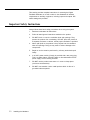
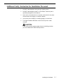
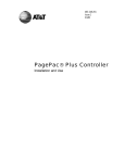
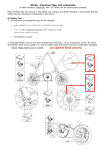
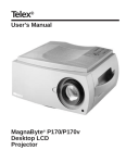
AT&T
Digital Feedback Eliminator
and Auto-Page Repeater
Installation and Use
AT&T 463-248-107
0II722700-007
Issue 2, November 1993
Copyright 1993 AT&T
All Rights Reserved
Written/Printed in U.S.A.
Notice
Every effort was made to ensure that the information in this guide was complete and accurate at the time
of printing. However, information is subject to change.
Trademarks
PAGEPAC, PAGEPAC PLUS, PAGEPAL, and AMPLICENTER are a trademark of HARRIS
CORPORATION.
Warranty
AT&T provides a limited warranty for this product. Refer to “AT&T Limited Warranty and Limitation of
Liability” in Appendix A.
Ordering Information
The order number for this book is 463-248-107. To order copies of this book, call 1-800-432-6600 in the
U.S. and 1-800 255-1242 in Canada. For more information on how to order this and other system
reference materials, see “Reference Materials,” in “About This Guide.” For information on ordering
replacement parts, accessories, and other compatible equipment, refer to “Product Ordering Information,”
in Section 1.
Support Telephone Numbers
AT&T provides a toll-free customer helpline 24 hours a day.
In the U.S., call the AT&T NTSC Group at 1-800-552-3293 or the AT&T Helpline at 1-800-628-2888 if you
need assistance when installing, programming, or using your system. For service or technical assistance
in Canada, call one of the following Technical Assistance Centers:
Eastern Canada and Ottawa:
Ontario:
Central and Western Canada:
1-800-363-1882
1-800-387-4268
1-800-663-9817
ii
VG—6/94—500
Contents
1.
■
■
■
■
■
■
■
■
■
2.
■
■
■
■
■
■
■
Important Safety Instructions
Example System Setup
Installation Steps
Tools Required
Mounting the Unit
Power Connections
Connecting to the Paging System
■
1-4
1-5
1-6
2-2
2-4
2-5
2-5
2-5
2-6
2-6
3-1
3-2
Automatic Operation
Setting Option Switches
3-2
A-1
Warranty Information
■
1-2
1-2
1-2
1-3
1-3
1-4
2-1
Operation
■
A.
About This Guide
How to Use This Guide
Reference Materials
How to Comment on This Guide
Shipping Container Contents
Ordering Information
Features and Capabilities
Specifications
Hardware Configuration
Installing the Hardware
■
3.
1-1
Overview
Limited Warranty and Limitation of Liability
Installation and Maintenance Information
iii
A-1
A-2
Overview
1
Contents
About This Guide
How to Use This Guide
Reference Materials
How to Comment on This Guide
Shipping Container Contents
Ordering Information
Features and Capabilities
Specifications
Hardware Configuration
1-2
1-2
1-2
1-3
1-3
1-4
1-4
1-5
1-6
Overview
1-1
The following paragraphs give a summary of this guide, and the features
and installation summary for the AT&T Digital Feedback Eliminator (DFE).
About This Guide
This installation and use guide explains the installation and configuration of
the AT&T Digital Feedback Eliminator. It gives interface instructions to
other communications equipment.
It is intended that Digital Feedback Eliminator be installed by a trained
telephone, audio, or electrical installer with basic electronic knowledge.
The DFE conforms to common installation practices and preferences found
within the Telcom Electrical and Commercial Sound installers manual.
How to Use This Guide
Before beginning hardware installation, review and understand the guide to
determine how the hardware is to be installed and set. The following
paragraphs summarize each topic within this guide.
■
Overview. This section describes the features and illustrates the
various parts of the DFE. Ordering information is included.
■
Installation of Hardware. This section provides instructions for
mounting the DFE on a wall or table. Detailed instructions for
connection and operation with paging systems is provided.
■
Operation. This section gives information on the unit’s automatic
operation. Switch settings are given for various modes of operation.
■
Maintenance and Customer Support. The industrial grade housing
and quality construction of the Digital Feedback Eliminator virtually
eliminates the need for service or maintenance. There are no
user-serviceable components. Should a problem arise which requires
technical assistance beyond the information provided in this guide, call:
AT&T Technical Support, 1-800-552-3293
AT&T National Technical Marketing, 1-800-222-1313
AT&T National Service Assistance Center, 1-800-628-8888.
Reference Materials
To order additional reference materials, call the AT&T Customer
Information Center:
In the U.S. 1-800-432-6600
In Canada: 1-800-255-1242
1-2
Overview
How to Comment on This Guide
Send your comments and recommendations for changes to:
M. McGinnis
809 Calle Plano
Camarillo, CA 93012-8516
FAX: (805) 987-2547
Shipping Container Contents
The following items should be found in the PagePac Plus Controller
shipping container. If something is missing, notify your local dealer.
■
Digital Feedback Eliminator
■
Package of four 1/2" mounting screws
■
RC-2 Pro Interface connector
■
Power Supply
■
This Installation and Use Guide
RC-2 PRO
INTERFACE
AT&T
DIGITAL FEEDBACK
ELIMINATOR
Digital Feedback Eliminator
and Auto-Page Repeater
Installation and Use
MOUNTING SCREWS
USER MANUAL
Figure 1-1. Shipping Container Contents
Overview
1-3
Ordering Information
Equipment is available from many AT&T sources. Contact any of the
following for sales information and advice on the equipment that would
best meet your needs:
AT&T
AT&T
AT&T
AT&T
■
Catalog Sales
Sales Office
Phone Center Store
Authorized Dealer
1-800-451-2100
1-800-247-7000
1-800-222-3111
1-800-247-1212.
Digital Feedback Eliminator, AT&T PEC 53645
COMCODE 463-248-107
(HD# 0II722700-007)
Features and Capabilities
The Digital Feedback Eliminator makes a digital recording of an
announcement and then broadcasts it over a paging system. This delayed
broadcast eliminates the possibility for audio feedback. Applications
include installations in which the telephone used for paging or microphone
is close to the paging loudspeakers, and environments with a high
potential for acoustic feedback.
1-4
Overview
■
Connects between a telephone system and a paging system.
■
Records an announcement in digital memory eliminating faint
background noises.
■
May be programmed to play the announcement once or twice.
■
Offers both Line level and Low impedance audio outputs.
■
Provides Record, Play, and Busy relay closures to control external
equipment.
■
May be activated by voice, DTMF, or contact closure.
■
Optional alert tone attracts listeners’ attention before page is made.
■
DTMF Message Cancel permits an in-progress message to be aborted.
Specifications
Table 1-1. Digital Feedback Eliminator Specifications
Physical
Electrical
■
Maximum dimensions: 10.4" (26 cm) wide by 8" (20 cm) high by 1.5" (3.75 cm) deep,
including RC-2 interface.
■
Weight: 3 pounds (1.36 kg).
■
Audio Input: 600 ohms, transformer isolated, with DC blocking capacitor, -15 dBm to 4
dBm (nominal -10 dBm) input level.
■
Line Output: Line level (600 ohms), transformer isolated, 10 dBm (maximum) output level.
■
Power Output: Low impedance (8 ohms), transformer isolated, limited to approximately 0.4
watts into 8 ohms, 10 dBm output level.
■
VOX Sensitivity: -21 dBm (minimum), recording released 3 seconds after last sensed audio.
■
Power requirement: 24 Vdc, 250 mA.
Environmental
■
Capable of operating in ambient temperatures from 0 to +40 C (+32 to +104 F) and relative
humidities from 0% to 85% (non-condensing), at altitudes up to 10,000 feet above sea level.
Interconnect
■
RC-2 Pro Interface connector (50-pin Amphenol) plugs into DFE. The other side of the
RC-2 has 20 screw down terminals.
Overview
1-5
Hardware Configuration
The information key that follows Figure 1-2, illustrates the location of each
of the Digital Feedback Eliminator controls and indicators.
AT&T
INPUT LEVEL
DTMF LEVEL
VOX LEVEL
(RED)
POWER
(GREEN)
PLAY
RECORD
POWER OUTPUT
AUDIO
LINE OUTPUT
(YELLOW)
BUSY
(RED)
FE-2HDA
DIGITAL FEEDBACK ELIMINATOR
& AUTO-PAGE REPEATER
Figure 1-2. Digital Feedback Eliminator Controls and Indicators
1-6
Overview
Power light. Glows RED to indicate that power has been applied to
the unit.
Play light. Glows GREEN while a message is being played.
Record light. Glows YELLOW while a message is being recorded.
Busy light. Glows RED while the unit is active, recording or playing
a message.
Input Level control. Adjusts the volume of the audio input.
IMPORTANT! Do not addjust
items 5, 6, 7, 8, and 9. These
controls are factory set .
DTMF Level control. Adjusts the sensitivity of the DTMF decoder
circuit.
VOX Level control. Adjusts the sensitivity of the Voice detection
circuit.
Power Output control. Controls the volume of the Low impedance
(8) audio output.
Line Output control. Controls the volume of the Line level (600 )
audio output.
Interface connector. Male 50-pin Amphenol connector; accepts
RC2 Pro Interface. Provides all connections to the Digital Feedback
Eliminator, including power, audio, and control inputs and outputs.
Option switches. Two blocks of DIP switches, located under a
plastic cover. Used to select recording length, activation method
(voice, DTMF, or contact closure), page alert tone, and other options.
Overview
1-7
Installing the Hardware
2
Contents
Important Safety Instructions
■
Additional Safety Instruction for Installation Personnel
Example System Setup
Installation Steps
Tools Required
Mounting the Unit
Power Connections
Connecting to the Paging System
2-2
2-3
2-4
2-5
2-5
2-5
2-6
2-6
■
Using an RC-2 Pro Interface Connector
2-7
■
Control Inputs
2-8
■
Control Outputs
2-8
■
Using an Amphenol Connector
2-9
Installing the Hardware
2-1
This section provides complete instructions for mounting the Digital
Feedback Eliminator on a wall or table. It also illustrates all interface
requirements to auxiliary equipment, including inputs and outputs. DIP
switch settings are provided.
Important Safety Instructions
Always follow these basic safety precautions when using the system:
2-2
Installing the Hardware
1.
Read and understand all instructions.
2.
Follow all warnings and instructions marked on the product.
3.
DO NOT block or cover the ventilation slots and openings. They
prevent the product from overheating. DO NOT place the product in
a separate enclosure or cabinet, unless proper ventilation is provided.
4.
Never spill liquid on the product or drop objects into the ventilation
slots and openings. Doing so may result in serious damage to the
components.
5.
Repair or service must be performed by a factory authorized repair
facility.
6.
A 24 VDC power module (if used) is provided with a two-prong plug.
This is a safety feature. DO NOT staple or otherwise attach the DC
power supply cord to building surfaces.
7.
DO NOT use the product near water or in a wet or damp place
(such as a wet basement).
8.
DO NOT use extension cords. Install product within six feet of a
grounded outlet receptacle.
Additional Safety Instruction for Installation Personnel
1.
DO NOT install telephone wiring during a lightning storm.
2.
DO NOT install telephone jacks in a wet location unless the jack is
specifically designed for wet locations.
3.
Never touch uninsulated wires or terminals, unless the line has been
disconnected at the paging or controller interface.
4.
Use caution when installing or modifying paging or control lines.
5.
The Digital Feedback Eliminator must be securely wall or table
mounted.
CAUTION:
If any wiring from the paging system leaves the building premises,
you must install AT&T 503A1 IROB protectors.
Installing the Hardware
2-3
Example System Setup
The Digital Feedback Eliminator can be configured in several ways
depending on the paging system used. The following illustration shows a
typical installation.
DRY LOOP CONTACT CLOSURE
TO START RECORDING
RING
TIP
FROM HOST
TELEPHONE SYSTEM
AUDIO
UNIT
POWER
24 VDC
OPTION
SWITCHES
(–)
(+)
AMPLICENTER
3/4"PLYWOOD
TO SPEAKERS
Figure 2-1. Example Digital Feedback Eliminator Installation
2-4
Installing the Hardware
Installation Steps
These are the general steps for installation.
1.
Mount the unit to the wall or table.
2.
Make cable connections from DFE to paging system.
3.
Set DIP switches to desired unit operation.
4.
Power up DFE unit.
5.
Test DFE unit.
Tools Required
The following tools are required for the installation of the unit hardware and
cabling.
■
Standard screwdriver (small and large)
■
Phillips Screwdriver (#1 and #2)
■
Wire strippers (24 Awg -12 Awg)
■
Tone out circuit tester
■
Volt-Ohm Meter
■
You will also need the following additional materials and equipment:
■
AT&T-type 103 or 104 connection block and wire
■
24 VDC power supply
Mounting the Unit
1.
Find space on the wall or table.
2.
Mount the Digital Feedback Eliminator and its wiring at least 18"
away from any power supply or other equipment that generates
electrical noise.
3.
Make sure there is enough clearance (at least 4") for you to attach
the RC-2 Pro Interface to the left side of the unit.
4.
Make sure there is a standard electrical outlet into which you can
plug your 24 Vdc power supply. This outlet should not be controlled
by a switch.
5.
Position the unit on the board or table and mount it securely using
screws.
6.
Attach the RC-2 Pro Interface to the Interface connector on the left
side of the unit.
Installing the Hardware
2-5
Power Connections
1.
Make sure the 24 Vdc power supply is unplugged.
2.
Connect the minus (-) side of the power supply to terminal #19 of
the RC-2 Pro interface.
3.
Connect the positive (+) side of power supply to terminal #20 of the
RC-2 Pro interface.
4.
Plug in the power supply. The Power light should glow RED.
5.
Turn off the power supply while making other interface connections.
Connecting to the Paging System
The Digital Feedback Eliminator is typically installed between the
telephone system and the paging system, as is shown in Figure 2-2. It
interfaces with the paging controller in a zone paging environment, and
with the amplifier in a single-zone installation.
14 GREEN
11
TIP
12
RING
1
x
PAGING SYSTEM
FEEDBACK ELIMINATOR
HOST SYSTEM PAGE PORT
2
6
9
AUDIO IN
LINE OUT
COM
RPLAY
RECORD
RCOM
xRCOM
RBUSY1
+24 VDC
-24 VDC
13 RED
TIP
RING
7 YELLOW
x 6 BLACK
C1
GND
20
19
DRY LOOP CLOSURE
"BUSY" CLOSURE
BACK TO HOST
SYSTEM
–
+
24 VDC POWER SUPPLY
Figure 2-2. Digital Feedback Eliminator Connections to Telephone System and Paging
2-6
Installing the Hardware
Using an RC-2 Pro Interface Connector
The RC-2 Pro Interface Connector (see Figure 2-3) attaches to the
Amphenol Interface connector on the Digital Feedback Eliminator. It
provides convenient wire access for the power, audio, and control
connections to the unit using the screw-down terminals. The terminal
connections to the RC-2 Pro Interface are described in Table 2-1.
Figure 2-3. RC-2 Pro Interface Connector
Table 2-1. RC-2 Pro Interface Connector Terminal Functions
Terminal
Label
Function
1
COM
Control common
2
REC
Record control
3
PLAY
Play control
4
ABORT
Abort control
6
RCOM
Relay common
7
RPLAY
Play relay
8
RREC
Record relay
9
RBUSY1
Busy 1 relay
10
RBUSY2
Busy 2 relay
11,12
AUDIO IN
Audio input
13, 14
LINE OUT
Line level (600 Ω ) audio output
15, 16
8 OHM OUT
19
–
24 Vdc input (–)
20
+
24 Vdc input (+)
Low impedance (8 Ω ) audio output
Installing the Hardware
2-7
Control Inputs
Control common (COM). Serves as common return for all control inputs
(REC, PLAY, ABORT).
Record control (REC). A closure between this input and Control common
(COM) causes the unit to record a message. The recording will terminate
when the closure is removed or the maximum record time is reached. The
Record control may be used even if the option switches have been set for
voice or DTMF activation.
Play control (PLAY). A momentary closure between this input and
Control common (COM) causes the unit to play the last recorded
message. The Play control may be used even if the option switches have
been set to play the message automatically after it has been recorded.
Abort control (ABORT). A closure between this input and Control
common (COM) aborts the current operation. To cancel a recording:
apply an Abort closure, remove the Record closure, then remove the Abort
closure. The unit will terminate the recording and bypass automatic
playback (if enabled). To restart a recording: apply a short Abort closure
while maintaining the Record closure. When the Abort closure is removed,
the unit will being recording a new message. To cancel playback: apply a
momentary Abort closure. The unit will stop playing the message
Control Outputs
Relay common (RCOM). Serves as common return for all relay outputs
(RPLAY, RREC, RBUSY1 , RBUSY2).
Play relay (RPLAY). Provides a closure with Relay common (RCOM)
while a message is being played. It remains open during the initial Page
Delay period (as well as between messages if the option switches have
been set to Auto-Play Twice).
Record relay (RREC). Provides a closure with Relay common (RCOM)
while a message is being recorded.
Busy relay (RBUSYx). Provides a closure with Relay common (RCOM)
while a message is being recorded or played. It remains closed during the
entire time the unit is active—including the delay between Record and
Auto-Play, and the delay between pages if the Auto-Play Twice option has
been selected. The unit provides two sets of relay outputs, RBUSY1 and
RBUSY2.
2-8
Installing the Hardware
Using an Amphenol Connector
If the RC-2 Pro lnterface is not appropriate for your application, you can
replace it by running a 25-pair cable with a female Amphenol connector
from the interface connector on the Digital Feedback Eliminator to a
66B-type punchdown block in standard color code order. Table 2-2 lists
the pin assignments for the Interface connector.
Table 2-2. Amphenol Interface Connector Wiring.
Function
AUDIO IN high
RC-2
Term
Wire
Color
Pin No
Pin No
Wire
Color
RC-2
Term
[11]
W-BL
26
1
BL-W
[12]
W-O
27
2
O-W
N/C
Function
AUDIO IN return
N/C
LINE OUT
[13]
W-GR
28
3
GR-W
[14]
LINE OUT return
8 OHM OUT
[16]
W-BR
29
4
BR-W
[15]
8 OHM OUT return
W-S
30
5
S-W
N/C
N/C
Common
[1]
R-BL
31
6
BL-R
[2]
Record
Common
[1]
R-O
32
7
O-R
[3]
Play
Common
[1]
R-G
33
8
G-R
[4]
Abort
Common
[1]
R-BR
34
9
BR-R
[5]
Spare
R-S
35
10
S-R
Play Relay (NC)
Play Relay (NC)
Play Relay (COM)
[6]
BK-BL
36
11
BL-BK
[6]
Play Relay (COM)
Play Relay (NO)
[7]
BK-O
37
12
O-BK
[7]
Play Relay (NO)
BK-G
38
13
G-BK
Record Relay (NC)
Record Relay (NC)
Record Relay (COM)
[6]
BK-BR
39
14
BR-BK
[6]
Record Relay (COM)
Record Relay (NO)
[8]
BK-S
40
15
S-BK
[8]
Record Relay (NO)
Busy 1 Relay (COM)
[6]
Y-BL
41
16
BL-Y
[6]
Busy 1 Relay (COM)
Y-O
42
17
O-Y
Busy 1 Relay (NC)
Busy 1 Relay (NC)
Busy 1 Relay (NO)
[9]
Y-G
43
18
G-Y
[9]
Busy 1 Relay (NO)
Busy 2 Relay (COM)
[6]
Y-BR
44
19
BR-Y
[6]
Busy 2 Relay (COM)
Y-S
45
20
S-Y
V-BL
46
21
BL-V
N/C
V-O
47
22
O-V
N/C
N/C
V-G
48
23
G-V
N/C
Busy 2 Relay (NC)
Busy 2 Relay (NO)
[10]
Busy 2 Relay (NC)
[10]
Busy 2 Relay (NO)
24 Vdc input (+)
[20]
V-BR
49
24
BR-V
[19]
24 Vdc input (–)
24 Vdc input (+)
[20]
V-S
50
25
S-V
[19]
24 Vdc input (–)
Installing the Hardware
2-9
Operation
3
Contents
Automatic Operation
Setting Option Switches
3-2
3-2
■
Switch Block #1
3-3
■
Switch Block #2
3-5
Operation
3-1
Automatic Operation
Operation of the Digital Feedback Eliminator is automatic once installed
and configured. When a page is made, the message is digitized and
stored in memory. When the page ends, the digitized message is released
to play over the paging system’s speakers. Since the live microphone is off
at the time of subsequent amplified page, feedback is eliminated.
Speakers can thus be set at any volume level.
The Record command from the external source can be set for a number of
forms as described in the next paragraph, “Setting Option Switches.”
Setting Option Switches
The Digital Feedback Eliminator has two blocks of DIP switches which set
the operation parameters of the unit. They are located under a pop-off,
plastic cover on the front of the unit.
SWITCH BLOCK #1
Figure 3-1. DIP Switches Option
3-2
Operation
SWITCH BLOCK #2
Switch Block #1
Note: If you change the setting
of the Recording Length DIP
switch while the unit is powered
on, you will have to cycle power
(turn the power off and back on
again) before the unit will
recognize the new setting.
■
Recording Length — This option sets the maximum duration of the
recorded message to either 30 at 6.8 kHz or 60 seconds at 3.4 kHz.
The recording will automatically terminate at the end of this time, even
if the Record contacts are still active. This option also controls the
audio fidelity of the recording by setting the digital sampling rate. The
factory default for this option is 30 seconds.
1
■
Recording Length
↓
60 seconds at 3.4 kHz
↑
30 seconds at 6.8 kHz
DTMF Option — This option specifies how the Digital Feedback
Eliminator should respond if the user enters DTMF digits (by pressing
the keys on a touch-tone phone) while a message is being recorded.
If No restrictions are in effect, any DTMF tones will be recorded and
played back through the paging system. If Allow two bursts has been
selected, the user may record up to two DTMF digits; the third
keypress will abort the recording and cancel automatic playback. The
Allow one burst option permits a single DTMF digit to be recorded.
The Allow no bursts setting causes the unit to abort the recording on
the first DTMF digit it receives.
If the DTMF activation option is in effect (see Recording Method,
below), the initial burst of DTMF (the one that starts the recording) is
not recorded, and does not count toward the maximum number of
bursts allowed.
The unit keeps track of the total number of DTMF bursts received. The
bursts do not have to be consecutive. You may need to adjust the
DTMF Level control to ensure that DTMF tones are correctly
recognized.
2
3
↓
↓
No restrictions
↑
↓
Allow two bursts
↓
↑
Allow one burst
↑
↑
Allow no bursts
DTMF Option
Operation
3-3
■
Recording Method — This option specifies whether recording is to be
initiated by voice, DTMF, or contact closure. If DTMF activation is
selected, the unit will start recording a message after it detects a DTMF
tone (caused by the user pressing a key on a touch-tone phone). The
tone will not be included in the recording. If Voice activation is
selected, the unit will begin recording the moment the user starts
speaking. In both cases, recording will end approximately three
seconds after the end of the page.
You may need to adjust the DTMF Level and VOX Level controls to
ensure that DTMF tones and audio levels are measured correctly.
Recording may always be initiated by operating the Record contact
closure. It will terminate immediately after the closure is removed if
Closure activation has been selected; it will end approximately three
seconds after the page if the option switches have been set for voice or
DTMF activation.
■
4
5
↓
↓
Closure activation
↑
↓
DTMF activation
↓
↑
Voice activation
Recording Method
Playback Method — This option specifies how playback is initiated.
The default setting is Auto-Play Once: the message is played back
immediately after it is recorded, or in response to a momentary closure
on the Play control. If Auto-Play Twice is selected, the message will be
repeated (played back twice).
The Play while closure active option suppresses automatic playback;
the message will be played in response to a closure on the Play
control. The message will be repeated as long as the closure is
maintained. The Play once by closure option operates similarly, but it
requires that the Play contact be opened and then closed again before
the message will be repeated.
Note: The Pre-Page Tone
should be disabled if the Digital
Feedback Eliminator is being
used with a zone paging system;
otherwise, the paging controller
may interpret the DTMF tone as
a request to select a zone.
3-4
Operation
6
7
Playback Method
↓
↓
Play while closure active
↑
↓
Play once by closure
↓
↑
Auto-play once
↑
↑
Auto-play twice
■
Pre-Page Tone — This option instructs the unit to broadcast a
three-second alert tone (the DTMF digit 0) before it plays back the
recorded message. The tone will only be played once: it will not be
repeated if the Auto-Play Twice option is in effect. (Pre-Page Tone is
also called Pre-Announcement Tone.)
Pre-Page Tone
8
↓
Pre-page tone disabled
↑
Pre-page tone enabled
Switch Block #2
■
■
Page Delay — This option specifies the length of time the unit should
wait between recording a message and playing it back if automatic
playback is in effect. It also controls the interval between repetitions if
the Auto-Play Twice option has been selected.
1
2
↓
↓
1 second delay
↑
↓
3 second delay
↓
↑
5 second delay
↑
↑
10 second delay
Page Delay
Pre-Record Tone — This option instructs the unit to send a confirming
tone to the user before it begins recording. (Pre-Record Tone is also
called User Confirmation Tone.)
Pre-Record Tone
3
4
↓
—
Pre-record tone disabled
↑
—
Pre-record tone enabled
Operation
3-5
Warranty Information
A
Limited Warranty and Limitation of Liability
AT&T warrants to you that the product will be free from defects in material
and workmanship when title passes to you. If you notify AT&T that the
product has failed to operate as warranted within one year of the date title
passes to you, AT&T will, at its option, repair or replace the component or
components of the product that failed to operate as warranted. Any repair
or replacement components may be new or refurbished and will be
provided on an exchange basis. If AT&T determines that the product
cannot be replaced, AT&T will refund the purchase price to you.
If you purchased the product directly from AT&T, AT&T will perform
warranty repair on your premises in accordance with the terms and
conditions of AT&T’s “Business Day” or “Around-the-Clock” warranty
plans. The details of AT&T’s warranty plans may be obtained from AT&T.
If you purchased the product from an authorized dealer, you will be
covered by AT&T’s authorized dealer warranty plan during the warranty
period. Contact your authorized dealer for details of AT&T’s authorized
dealer warranty plan. AT&T’s obligation to repair, replace or refund as
set forth above is your exclusive remedy.
The limited warranties provided above do not cover damages, defects,
malfunctions or product failures caused by:
■
Failure to follow AT&T’s installation, operation or maintenance instructions;
■
Unauthorized modification or alteration of the product or its components;
■
Product abuse, misuse or the negligent acts of persons not under the
reasonable control of AT&T;
■
Actions of third parties and acts of God other than power surges (e.g.,
lightning).
Warranty Information
A-1
This limited warranty applies only to the product purchased directly from
AT&T or purchased directly from an authorized AT&T dealer.
You may be required to provide AT&T with proof of purchase before AT&T
will perform any warranty repair or provide any warranty replacements.
EXCEPT AS SPECIFICALLY SET FORTH ABOVE, AT&T, ITS
AFFILIATES, SUPPLIERS AND DEALERS MAKE NO WARRANTIES,
EXPRESS OR IMPLIED, AND SPECIFICALLY DISCLAIM ANY
WARRANTY OF MERCHANTABILITY OR FITNESS FOR A
PARTICULAR PURPOSE.
EXCEPT FOR PERSONAL INJURY, THE LIABILITY OF AT&T, ITS
AFFILIATES, SUPPLIERS AND DEALERS FOR ANY CLAIM, LOSS,
DAMAGE OR EXPENSE FROM ANY CAUSE WHATSOEVER,
REGARDLESS OF THE FORM OF THE ACTION, WHETHER IN
CONTRACT, TORT OR OTHERWISE, SHALL NOT EXCEED THE
LESSER OF DIRECT DAMAGES PROVEN OR THE REPAIR OR
REPLACEMENT COST OF THE SYSTEM OR THE SYSTEM’S
PURCHASE PRICE. IN NO EVENT SHALL AT&T, ITS AFFILIATES,
SUPPLIERS AND DEALERS BE LIABLE FOR INCIDENTAL, RELIANCE,
CONSEQUENTIAL OR ANY OTHER INDIRECT LOSS OR DAMAGE
(INCLUDING LOST PROFITS OR REVENUES SUSTAINED OR
INCURRED IN CONNECTION WITH THE SYSTEM). THIS LIMITATION
OF LIABILITY SHALL SURVIVE FAILURE OF THE EXCLUSIVE
REMEDY SET FORTH IN THE LIMITED WARRANTY ABOVE.
Installation and Maintenance Information
There are several types of installation and maintenance plans available
from AT&T and/or your dealer. Please call your AT&T sales representative
or authorized dealer for details.
For warranty service, contact your AT&T representative or authorized
dealer.
A-2
Warranty Information
© 1993 AT&T
All rights reserved
Printed in U.S.A.
AT&T 463-248-107
0II722700-007
Issue 2, November, 1993
Graphics © AT&T 1988