1
OWNER ’S GUIDE
INSTALLATION GUIDE
Headrest Video Monitor
MODEL HVM500
Table of Contents
Warranty . . . . . . . . . . . . . . . . . . . . . . . . . . . . . . . . . . . . . . . . . . . . . . . . .4
Safety Instructions . . . . . . . . . . . . . . . . . . . . . . . . . . . . . . . . . . . . . . . . . .5
Important Safeguards . . . . . . . . . . . . . . . . . . . . . . . . . . . . . . . . . . . . . . . .5
When Cleaning the Vehicle ..........................................................................................................5
While Driving ............................................................................................................................5
When Parked .............................................................................................................................5
Proper Use ...............................................................................................................................5
Repairs .....................................................................................................................................5
Important Information . . . . . . . . . . . . . . . . . . . . . . . . . . . . . . . . . . . . . . .6
FCC Notice ................................................................................................................................6
Your Warranty ...........................................................................................................................6
Features . . . . . . . . . . . . . . . . . . . . . . . . . . . . . . . . . . . . . . . . . . . . . . . . .6
Features ...................................................................................................................................6
Accessories ...............................................................................................................................6
Basic Operation . . . . . . . . . . . . . . . . . . . . . . . . . . . . . . . . . . . . . . . . . . . .7
Monitor Description ...................................................................................................................7
Viewing Angle ...........................................................................................................................7
Maintenance ............................................................................................................................7
On-Screen Menus . . . . . . . . . . . . . . . . . . . . . . . . . . . . . . . . . . . . . . . . . . .8
Making Changes to System Settings .............................................................................................8
Setup Menu Descriptions and Operation ........................................................................................9
System Settings Menu ................................................................................................................10
Hardware Options Menu ..............................................................................................................10
Assign Source Names Menu .........................................................................................................11
Assign Trigger Names Menu .........................................................................................................12
Source Names ...........................................................................................................................12
Trigger Names ...........................................................................................................................12
Installation . . . . . . . . . . . . . . . . . . . . . . . . . . . . . . . . . . . . . . . . . . . . . . .13
Monitor Specifications ................................................................................................................13
Installation Options ...................................................................................................................13
Installation ..............................................................................................................................13
Wiring Guide . . . . . . . . . . . . . . . . . . . . . . . . . . . . . . . . . . . . . . . . . . . . . .14
Wiring Precautions .....................................................................................................................14
Wire and AV Connectors...............................................................................................................14
© 2001 Directed Electronics, Inc.
3
Limited Three-Year Warranty
For a period of THREE YEARS from the date of purchase,
troubleshooting or reinstallation of the unit. For service on
Directed Electronics, Inc. ("DIRECTED") promises to the
an out-of-warranty product a flat fate fee by model is
original purchaser to repair or replace, free of cost, with a
charged. Contact your authorized dealer to obtain the serv-
comparable reconditioned model any VIDEO MONITOR
ice charge for your unit.
(hereafter the "UNIT"), which proves to be defective in
workmanship or material defect under normal and reasonable use during the first 3 years after the purchase and
installation of the unit provided the following conditions
are met: the unit was purchased and installed by an authorized DIRECTED dealer; the unit remains in the vehicle in
which the unit was originally installed; and the unit is
returned to DIRECTED.
The unit in question must be
returned to DIRECTED postage paid and must be accompanied by a clear, legible copy of the bill of sale bearing the
following information:
TO THE MAXIMUM EXTENT ALLOWED BY LAW, ALL WARRANTIES, INCLUDING BUT NOT LIMITED TO EXPRESS WARRANTY, IMPLIED WARRANTY, WARRANTY OF MERCHANTABILITY, FITNESS FOR PARTICULAR PURPOSE AND
WARRANTY OF NON-INFRINGEMENT OF INTELLECTUAL
PROPERTY, ARE EXPRESSLY EXCLUDED; AND DIRECTED
NEITHER ASSUMES NOR AUTHORIZES ANY PERSON OR
ENTITY TO ASSUME FOR IT ANY DUTY, OBLIGATION OR
LIABILITY IN CONNECTION WITH ITS PRODUCTS. DIRECTED DISCLAIMS AND HAS ABSOLUTELY NO LIABILITY FOR
ANY AND ALL ACTS OF THIRD PARTIES INCLUDING DEAL-
■
Date of Purchase
ERS OR INSTALLERS. IN THE EVENT OF A CLAIM OR A DIS-
■
Your Full name and address
PUTE INVOLVING DIRECTED OR ITS SUBSIDIARY, THE
■
Authorized dealer's company name and address
■
Type of unit installed
APPLICABLE FEDERAL LAWS SHALL APPLY AND GOVERN
■
Year, make and model of the automobile
THE DISPUTE.
■
Automobile license number
■
Vehicle Identification number
■
Installation receipts
PROPER VENUE SHALL BE SAN DIEGO COUNTY IN THE
STATE OF CALIFORNIA.
CALIFORNIA STATE LAWS AND
THE MAXIMUM RECOVERY UNDER ANY
CLAIM AGAINST DIRECTED SHALL BE STRICTLY LIMITED
TO THE AUTHORIZED DIRECTED DEALER'S PURCHASE
PRICE OF THE UNIT. DIRECTED SHALL NOT BE RESPONSIBLE FOR ANY DAMAGES WHATSOEVER, INCLUDING BUT
All components and accessories other that the unit, includ-
NOT LIMITED TO, ANY CONSEQUENTIAL DAMAGES, INCI-
ing without limitation the remote control, cables and
DENTAL DAMAGES, DAMAGES FOR THE LOSS OF TIME,
installation accessories carry a 60-day warranty from the
LOSS OF EARNINGS, COMMERCIAL LOSS, LOSS OF ECO-
date of purchase of the same.
NOMIC OPPORTUNITY AND THE LIKE. NOTWITHSTANDING
THE ABOVE, THE MANUFACTURER DOES OFFER A LIMITED
This warranty is automatically void if the unit is bought
WARRANTY TO REPLACE OR REPAIR THE CONTROL MOD-
from anyone other than an authorized dealer, the unit's
ULE AS DESCRIBED ABOVE. Some states do not allow lim-
date code or serial number is defaced, missing or altered;
itations on how long an implied warranty will last or the
the unit has been modified or used in a manner contrary to
exclusion or limitation of incidental or consequential dam-
its intended purpose; or the unit has been damaged by
ages. This warranty gives you specific legal rights and you
accident, unreasonable use, neglect, improper service,
may also have other rights that vary from State to State.
installation or other causes not arising out of defects in
DIRECTED does not and has not authorized any person or
workmanship, materials or construction. This warranty is
entity to create for it any other obligation, promise, duty
nontransferable and does not cover batteries. This warran-
or obligation in connection with this UNIT.
ty does not cover labor costs for the removal, diagnosis,
4
© 2001 Directed Electronics, Inc.
Safety Instructions
WARNING:
TO REDUCE THE RISK OF FIRE OR ELECTRIC SHOCK, DO NOT EXPOSE THIS EQUIPMENT TO
RAIN OR MOISTURE. TO REDUCE THE RISK OF FIRE OR ELECTRIC SHOCK AND ANNOYING
INTERFERENCE, USE ONLY THE INCLUDED HARDWARE.
THIS MONITOR IS ONLY DESIGNED FOR REAR SEAT PASSENGER VIEWING AND IS NOT
INTENDED FOR VIEWING BY THE DRIVER WHILE THE VEHICLE IS IN MOTION. SUCH USE MAY
DISTRACT THE DRIVER OR INTERFERE WITH THE SAFE OPERATION OF THE VEHICLE, AND
MAY ALSO VIOLATE STATE LAW.
DIRECTED ELECTRONICS, INC. DISCLAIMS ANY LIABILITY FOR ANY BODILY INJURY,
INCLUDING FATALITIES, OR PROPERTY DAMAGE THAT MAY RESULT FROM ANY IMPROPER OR
UNINTENDED USES OF THIS PRODUCT.
■
Only operate the monitor as described in this
guide. Attempts to use or modify this monitor contrary to the descriptions in this guide
may cause damage and void the warranty.
■
Exposure to moisture or dust can cause
harmful damage to the internal electronics. Do not mount near cup holders or in
areas where spills may occur.
■
Extremes in temperature can cause abnormal display operation. This monitor has an
optimal operating temperature range
between 35-115 degrees Fahrenheit. If the
vehicle interior is outside this range, do
NOT operate the monitor until the temperature is within its operating range.
■
This monitor is designed for use in vehicles with standard (-) 12 volt ground electrical systems.
■
Do not operate for an extended period of
time without the engine running or the
vehicle’s battery voltage may drop to damaging levels.
Important Safeguards
WHEN CLEANING THE VEHICLE
PROPER USE
Do not spray this unit with water or cleaning
solutions. Moisture and the chemicals found in
cleaning fluids could damage the consoles finish
and interior electronics.
Do not touch the screen unless cleaning with a
soft dry cloth. Do not pull or hang from the fold
down monitor door.
WHILE DRIVING
If the monitor stops working for any reason, discontinue use immediately and consult with your
retailer about any necessary repairs.
This unit is intended for use in the rear seat area
only, and should not be installed in a location that
would allow the driver to view it while driving.
© 2001 Directed Electronics, Inc.
REPAIRS
5
Important Information
FCC NOTICE
YOUR WARRANTY
This device complies with Part 15 of FCC rules.
Your warranty registration must be completely
Operation is subject to the following two condi-
filled out and returned within 10 days of pur-
tions: (1) This device may not cause harmful
chase. Your product warranty will not be vali-
interference, and (2) this device must accept
dated if your warranty registration is not
any interference received, including interfer-
returned. Make sure you receive the warranty
ence that may cause undesired operation.
registration from your dealer. It is also neces-
Changes
or
modifications
not
expressly
approved by the party responsible for compliance could void the user's authority to operate
sary to keep your proof of purchase, which
reflects that the product was installed by an authorized dealer.
this device.
Features
6
FEATURES
ACCESSORIES
■
5.0" LCD screen with pivot.
■
Mounting bezel.
■
RCA video inputs for system flexibility.
■
Trim ring.
■
Easy to use adjustment controls.
■
Din-to-RCA cable, 5 meter.
■
Wireless IR remote control receiver built-in.
■
Screws and other mounting hardware.
■
Adjustable tilt trim bezel.
■
Front panel headphone output jack.
■
Front panel AV input jack.
■
Custom mounting trim ring for installation
flexibility.
■
Active matrix color TFT LCD.
■
Front panel controls.
■
On-screen display/programming.
NOTE: This product requires specialized tools and installation techniques; Directed recommends that this
monitor be installed by a retailer that employs
MECP (Mobile Electronics Certification Program)
installers. Contact your retailer for details.
Note: This manual makes reference to optional Directed
Video parts not included with this product.
© 2001 Directed Electronics, Inc.
Basic Operation
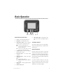
2 3 1 6 7 9
MONITOR DESCRIPTION
1.
Screen - TFT active matrix LCD screen.
2.
Input jack - for audio/video source.
3.
Power/Source button - press to turn the
monitor on/off or change video source.
■
4.
Press to turn the monitor on.
■
Press for more than three seconds to
turn the monitor off.
■
Press for less than three seconds
when on to change the source.
Headphone jack - insert the headphone
plug to listen to audio.
9.
6
5 4 8
LED indicator light - when turned on the
light is blue; when on standby the light is
red.
VIEWING ANGLE
The picture viewing angle can be easily adjusted by pressing against the top or bottom of the
monitor bezel.
MAINTENANCE
Keep the monitor clean and free of dust and
moisture and it will provide years of trouble-free
5.
IR remote input - for remote control
operation.
operation. Do not allow any cleaning fluids on
6.
Up/down buttons - volume and picture
adjustment.
chemicals that can harm the finish and diminish
■
7.
8.
Default volume control.
■
Adjusts programming when MODE is
pressed.
Mode button - changes up/down buttons
functions.
the monitor screen or bezel; they may contain
the picture quality.
To clean the monitor, simply use a soft, dry
cloth and gently wipe away any dirt. Avoid
applying too much pressure to the screen when
cleaning as it can result in damage.
Monitor Insert Cover
© 2001 Directed Electronics, Inc.
7
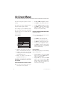
On-Screen Menus
The Setup Menu is a list of programming selec-
1.
Press MODE to enter the Setup Menu.
tions that control system operation and screen
2.
Press UP or DOWN to highlight the selection.
settings.
3.
Press MODE to enter that selection menu.
Each selection has a list of settings that can be
4.
Press UP or DOWN to highlight the setting.
changed to optimize system operation.
5.
Press MODE to change the setting, display
additional settings menus, or toggle
through a list of possible settings.
Some settings may have additional settings.
Notes that include any specific programming
instructions for these are included under the
selection heading.
SETUP MENU
USINGTHE UNIVERSAL REMOTE CONTROL
(Included with MCB1000)
NOTE: For a guide to remote control button locations
refer to the MCB1000 guide.
1.
Press MENU to enter the Setup Menu.
2.
Press (+) or (-) to highlight the selection.
3.
Press MENU to enter that selection menu.
4.
Press (+) or (-) to highlight the setting.
5.
Press MENU to change the setting, display
additional setting menus, or toggle through
a list of possible settings.
1.
Channel - only appears if the TVM300 TV
tuner is connected and TV is the source.
EXITING MENUS
2.
Security - only applies when ESP/ESP2
security systems are connected; only ESP2
will display trigger zones.
steps to exit the menus.
3.
After making setting changes, use the following
1.
Highlight BACK, press the monitor’s MODE
button or the remote’s MENU button to
return to the previous menu
2.
Highlight EXIT, press the monitor’s MODE
button or the remote control’s MENU
button or make no entry for eight seconds,
you will exit all menus and return to the
current video source display.
Setup - only appears if the MCB 1000
Expanded Menu switch is on.
MAKING CHANGES TO SYSTEM
SETTINGS
USING THE MONITOR CONTROL BUTTONS
NOTE: For a guide to monitor button locations refer to
Basic Operation section of this guide.
8
© 2001 Directed Electronics, Inc.
SETUP MENU DESCRIPTIONS AND OPERATION
Following are explanations of the many settings that can be changed to customize the operation of
your Rear Seat Entertainment system. To change the settings described, follow the directions in the
on-screen menu’s section or the special instructions in each menu.
SELECTION
DESCRIPTION AND OPERATION
VOLUME
■
■
CHANNEL (TVM300 ONLY)
■
■
DIMMER
■
■
■
■
PICTURE
■
Note: To adjust use the
monitor’s UP/DOWN buttons
or the remote's (+)/(-)
buttons.
■
OSD COLOR
■
■
■
■
■
■
■
SECURITY (ESP/ESP2 ONLY)
■
NOTE: This menu contains
selections that have additional settings.
■
■
SETUP (MCB1000 ONLY)
NOTE: This menu contains
selections that have additional
settings. This menu is used for
initial system setup only.
■
■
■
■
© 2001 Directed Electronics, Inc.
Adjust the volume of the headphone jack.
Use the monitors UP/DOWN or the remote’s (+)
(-) buttons to adjust the volume.
Change TV channels.
Use CHDN/CHUP buttons to change channels
Change illumination for day or night viewing.
HIGH - Sets illumination for viewing in daylight.
MEDIUM - Sets illumination for viewing in twilight.
LOW - Sets illumination for viewing at night.
Select to adjust picture.
BRIGHTNESS - Adjusts picture brightness.
COLOR - Adjusts picture color.
CONTRAST - Adjusts picture contrast.
HUE - Adjusts picture hue (NTSC only).
Select to change the color of the on-screen display.
WHITE - Changes the OSD to White.
GREEN - Changes the OSD to Green.
BLUE - Changes the OSD to Blue.
ESP/ESP2 programming and zone information.
TRIGGER INFORMATION - Displays ESP/ESP2 zone infor
mation. (Always displays the last zone triggered only.)
See the Assign Trigger Names menu.
SYSTEM SETTINGS - Displays the System Settings
menu. See the System Settings menu.
Change hardware settings and rename zones.
HARDWARE OPTIONS - Displays the Hardware
Options menu. See the Hardware Options menu.
ASSIGN SOURCE NAMES - Displays the Source
Names menu. See the Source Names menu for a
list of names.
ASSIGN TRIGGER NAMES - Displays the Trigger
Names menu. See the Trigger Names menu.
9
IMPORTANT!
Any changes in the following menus must be written into the MCB1000 and ESP/ESP2
software. Before the menu is exited the Write to System procedure must be completed.
SYSTEM SETTINGS MENU
SELECTION
DESCRIPTION AND OPERATION
PASSIVE/ACTIVE ARMING
Program the ESP/ESP2 security system to arm by itself
(passive) or if its remote must be used for arming
(active). For a full description of this setting refer to
your ESP/ESP2 owner’s guide.
CHIRPS ON/OFF
This feature will turn the arming and disarming chirps
on/off. For a full description of this setting refer to the
ESP/ESP2 owner’s guide.
IGNITION LOCK ON/OFF
When turned on, the doors will lock three seconds after
the ignition is turned on. For a full description of this
setting refer to the ESP/ESP2 owner’s guide.
IGNITION UNLOCK ON/OFF
When turned on, the doors will unlock when the ignition
is turned off. For a full description of this setting refer
to the ESP/ESP2 owner’s guide.
PASSIVE/ACTIVE LOCKING
This feature controls whether the doors will lock when
the ESP/ESP2 security system passively arms itself. For a
full description of this setting refer to your ESP/ESP2
owner’s guide.
WRITE TO SYSTEM
■
■
■
■
Highlight WRITE TO SYSTEM, press the monitor’s
MODE button or the remote's MENU button to
enter the system changes.
WRITING TO SYSTEM will be displayed.
WRITE SUCCESSFUL - Information entered successfully.
WRITE FAILED - Information not entered successfully.
HARDWARE OPTIONS MENU
SELECTION
DESCRIPTION AND OPERATION
POWER AUTO OFF
■
■
■
10
Select to choose POWER AUTO OFF or POWER LAST STATE.
POWER AUTO OFF - When the key is turned on the
system power will remain off, regardless of the system on/off state when the key was turned off.
POWER LAST STATE - When the key is turned on the
system will automatically return to the power
on/off state it was in when the key was turned off.
© 2001 Directed Electronics, Inc.
FM MODULATOR
■
■
■
■
ANTENNA TV
■
■
■
Select to let the MCB1000 know an FM modulator is
connected.
FM MODULATOR - allows the universal remote to turn
the FM modulator on/off.
NO FM MODULATOR - FM modulator control is defeated.
This FM Modulator function only applies when the
RFM100 is connected.
Select to choose Antenna or Cable input to TVM300.
Select ANTENNA TV when the TVA10 antenna is connected to the TVM300.
Select CATV when using a cable TV connection to
the TVM300.
CATV STD
■
Choose between three types of cable TV setups.
WRITE TO SYSTEM
■
Highlight WRITE TO SYSTEM, press the monitor’s
MODE button or the remote's MENU button to
enter the system changes.
WRITING TO SYSTEM will be displayed.
WRITE SUCCESSFUL - Information entered successfully.
WRITE FAILED - Information not entered successfully.
■
■
■
ASSIGN SOURCE NAMES MENU
NOTE: In this menu use the monitor’s MODE button or the remote’s MENU button to toggle through the available
choices for source names.
SELECTION
DESCRIPTION AND OPERATION
SOURCE 1: AV1
Select to change the name of source 1 from the source
names list at the end of this section.
SOURCE 2: AV2
Select to change the name of source 2 from the source
names list at the end of this section.
SOURCE 3: AV3
Select to change the name of source 3 from the source
names list at the end of this section.
WRITE TO SYSTEM
■
■
■
■
© 2001 Directed Electronics, Inc.
Highlight WRITE TO SYSTEM, press the monitor’s
MODE button or the remote's MENU button to
enter the system changes.
WRITING TO SYSTEM will be displayed.
WRITE SUCCESSFUL - Information entered successfully.
WRITE FAILED - Information not entered successfully.
11
ASSIGN TRIGGER NAMES MENU
NOTE: In this menu use the monitor’s MODE button or the remote’s MENU button to toggle through the available
choices for zone names.
SELECTION
DESCRIPTION AND OPERATION
ZONE 1
Select to change the name of zone 1 from the zone names
list at the end of this section.
ZONE 2
Shock sensor - Can not be changed.
ZONE 3
Door switch - Can not be changed.
ZONE 4
Select to change the name of zone 4 from the zone names
list at the end of this section.
ZONE 5
Ignition - Can not be changed.
ZONE 6
Select to change the name of zone 6 from the zone names
list at the end of this section.
ZONE 7
Select to change the name of zone 7 from the zone names
list at the end of this section.
ZONE 8
Select to change the name of zone 8 from the zone names
list at the end of this section.
WRITE TO SYSTEM
■
■
■
■
Highlight WRITE TO SYSTEM, press the monitor’s
MODE button or the remote's MENU button to
enter the system changes.
WRITING TO SYSTEM will be displayed.
WRITE SUCCESSFUL - Information entered successfully.
WRITE FAILED - Information not entered successfully.
.
12
SOURCE NAMES
TRIGGER NAMES
■
SOURCE X: VCR
■
ZONE X: HOOD/TRUNK SWITCH
■
SOURCE X: DVD
■
ZONE X: HOOD SWITCH
■
SOURCE X: GAME
■
ZONE X: TRUNK SWITCH
■
SOURCE X: CAMERA
■
ZONE X: FIELD SENSOR
■
SOURCE X: REAR CAMERA
■
ZONE X: MOTION/TILT SENSOR
■
SOURCE X: AUX INPUT PANEL
■
ZONE X: GLASS BREAK SENSOR
■
ZONE X: SHOCK SENSOR 2
© 2001 Directed Electronics, Inc.
Installation
MONITOR SPECIFICATIONS
6.
Route the cable through the headrest
access hole and the rear opening of the
mounting bezel. Leave enough slack in the
cable for monitor installation.
Screen size
5"
Resolution
74,880 pixels
View angle
Top 30 degrees
Bottom 10 degrees
Left 45 degrees
Right 45 degrees
7.
Install the bezel. Some headrests have
material that is strong enough to screw
the bezel into. Others will require quality
adhesive for mounting.
Video system
ntsc/pal
8.
Osd language
English
Power requirements
10 - 15 vdc
Route the cable through the seat cover
and reinstall the headrest. Leave enough
slack in the cable so the headrest still has
full movement during adjustment.
Operating temp.
35 - 115 degrees
fahrenheit
9.
Install the monitor into the mounting
bezel and adjust to the proper angle.
INSTALLATION OPTIONS
10. Complete the cable routing to the video
source.
The Directed HVM 500 5" monitor comes with a
mounting bezel designed for headrest installations.
INSTALLATION
1.
Remove the headrest cover to determine if
it has room in it for the monitor without
structurally weakening it.
2.
With the cover still removed, position the
cutout template against the rear of the
headrest and mark the area to be cut out.
3.
Remove the material to a depth sufficient
for the lip of the mounting bezel to fit
flush against the rear of the headrest once
installed.
4.
Cut an access hole for the cable to exit
next to the headrest adjustment bar.
5.
Reinstall the headrest cover. Trim it to the
size of the mounting bezel hole. When
trimming, it is best to leave extra material that can be glued into the hole before
installing the mounting bezel.
© 2001 Directed Electronics, Inc.
13
Wiring Guide
WIRING PRECAUTIONS
■
Route all wires and cables away from areas
where they could be pinched, punctured.
or chafe against sharp metal causing short
circuits.
■
All wires should be properly loomed and
fused at the source.
■
It is recommended that you have your
authorized retailer install this monitor.
Read all wiring information before attempting to
install this monitor.
■
■
Use only solder and tape or quality solderless connectors when terminating wires.
Incorrect or poor connections may cause
damage to the monitor or the vehicle.
Disconnect the ground wire from the battery or remove the fuses for any impacted
circuits before making any connections.
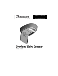
WIRE AND AV CONNECTORS
14
1.
Monitor DIN Cable
6.
Video Input RCA (YELLOW)
2.
DIN-to-RCA Cable
7.
Black Wire - Connect to chassis ground.
3.
IR Remote Connector
8.
4.
Audio Input RCA (RED)
5.
Audio Input RCA (WHITE)
Red Wire - Connect to a fused (+) 12 volt.
ignition accessory wire that turns off with
the key.
© 2001 Directed Electronics, Inc.
The company behind this system is Directed Electronics, Inc.
Since its inception, Directed has had one purpose, to provide consumers with the finest vehicle security, car stereo
products, rear seat entertainment, and accessories available. The recipient of more than 20 patents in the field of
advanced electronic technology, Directed is ISO 9001 registered.
Quality Directed Electronics products are sold and serviced throughout North America and around the world.
Call (800) 274-0200 for more information about our products and services.
Directed® is committed to delivering world-class quality products
and services that excite and delight our customers.
Directed Electronics, Inc.
Vista, CA 92083
www.directed.com
© 2001 Directed Electronics, Inc. - All rights reserved
N81101 Rev. 1.0 12-01