1
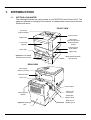
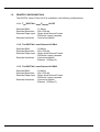
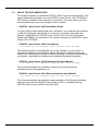
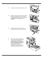
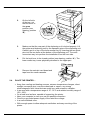
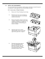
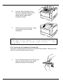
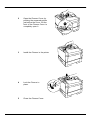
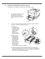
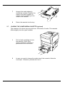
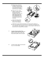
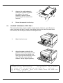
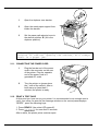
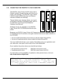
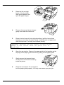
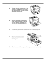
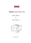
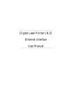
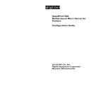
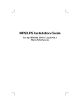
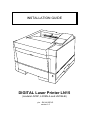
INSTALLATION GUIDE
DIGITAL Laser Printer LN15
(models LN15P, LN15N-A and LN15N-B)
p/n. : EK-LN15E-IG
version 1.0
2
Installation Guide DIGITAL Laser Printer LN15
CONTENTS
1. INTRODUCTION------------------------------------------------------------------------------------------4
1.1. GETTING ACQUAINTED------------------------------------------------------------------------4
1.2. PRINTER CONFIGURATIONS-----------------------------------------------------------------5
1.2.1. The DIGITAL Laser Printer LN15P------------------------------------------------------5
1.2.2. The DIGITAL Laser Printer LN15N-A---------------------------------------------------5
1.2.3. The DIGITAL Laser Printer LN15N-B---------------------------------------------------5
1.3. ABOUT THE DOCUMENTATION -------------------------------------------------------------6
2. SETTING UP YOUR PRINTER -----------------------------------------------------------------------7
2.1. UNPACKING THE PRINTER -------------------------------------------------------------------7
2.2. INSTALLING THE DUPLEXING UNIT (OPTIONAL)----------------------------------------8
2.3. INSTALLING THE LOWER MEDIA TRAY (OPTIONAL) -------------------------------- 10
2.4. PLACE THE PRINTER… ---------------------------------------------------------------------- 11
2.5. INSTALLING CONSUMABLES-------------------------------------------------------------- 12
2.5.1. Installing the Toner Cartridge----------------------------------------------------------- 12
2.5.2. Installing the Cleaner and Cleaner Pad ---------------------------------------------- 13
2.6. LOADING THE UPPER MEDIA CASSETTE (STANDARD)----------------------------- 15
2.7. LOADING THE LOWER MEDIA CASSETTE (OPTIONAL)----------------------------- 17
2.8. LOADING THE MANUAL FEED TRAY---------------------------------------------------- 19
2.9. USING THE REAR STACKER (STANDARD) ----------------------------------------------- 20
2.10. USING THE REAR STACKER (WITH OPTIONAL DUPLEXING UNIT) ------------------- 20
2.11. CONNECTING THE POWER CORD ----------------------------------------------------- 21
2.12. PRINT A TEST PAGE ------------------------------------------------------------------------ 21
2.13. MESSAGE WINDOW ------------------------------------------------------------------------- 22
2.14. IF SOMETHING GOES WRONG ---------------------------------------------------------- 22
2.15. INSTALLING MORE OPTIONS ------------------------------------------------------------ 22
2.16. CONNECTING THE PRINTER TO YOUR COMPUTER----------------------------- 23
2.17. THE ETHERNET INTERFACE QUICK CONFIGURATION (OPTIONAL)---------- 24
2.17.1. General Configuration------------------------------------------------------------------- 24
2.17.2. LAT Configuration------------------------------------------------------------------------ 24
2.17.3. TCP/IP Configuration ------------------------------------------------------------------- 24
2.17.4. Windows NT Configuration ------------------------------------------------------------ 25
2.17.5. Windows 95 Configuration ------------------------------------------------------------- 25
2.17.6. NetWare Configuration (NDS) -------------------------------------------------------- 25
3. THE CONTROL PANEL ------------------------------------------------------------------------------ 26
3.1. CONTROL PANEL INDICATORS----------------------------------------------------------- 26
3.2. CONTROL PANEL KEYS --------------------------------------------------------------------- 27
4. CONTROL PANEL MENU --------------------------------------------------------------------------- 28
5. TROUBLESHOOTING -------------------------------------------------------------------------------- 29
6. OPTIONS AND SUPPLIES -------------------------------------------------------------------------- 33
Installation Guide DIGITAL Laser Printer LN15
3
1. INTRODUCTION
1.1.
GETTING ACQUAINTED
The drawings illustrate the various parts of your DIGITAL Laser Printer LN15. The
parts are referred to throughout this manual, so please take some time to become
familiar with them.
FRONT VIEW
Top Cover
(Paper stacker)
Control Panel
Upper Door
Side Cover
(font card slot and
RAM card slots
inside)
Front Cover
(closed)
Transport grip
(both sides)
Lower Tray
Upper Tray
Optional Lower Media
Cassette (450 sheets)
Upper Media Cassette
(500 sheets)
REAR VIEW
Rear Printer
Stacker (closed)
Interface Panel
Lock Lever
Power Switch
Rear Duplexer
Stacker
Power Cord
Connector
Paper path
selector lever
Optional Duplexing
Unit
4
Base unit of
duplexing unit
Installation Guide DIGITAL Laser Printer LN15
1.2.
PRINTER CONFIGURATIONS
The DIGITAL Laser Printer LN15 is available in the following configurations:
1.2.1. THE DIGITAL LASER PRINTER LN15P
Standard RAM
: 11 Mbyte
Standard Resolution : 600 x 600 dpi
Standard Paper input : Single-sheet Manual Feeder
: 500-sheet (upper) cassette
Standard Interfaces : Centronics parallel
1.2.2. THE DIGITAL LASER PRINTER LN15N-A
Standard RAM
: 19 Mbyte
Standard Resolution : 600 x 600 dpi
Standard Paper input : Single-sheet Manual Feeder
: 500-sheet (upper) cassette
Standard Interfaces : Centronics parallel
: Ethernet (10-Base-2)
1.2.3. THE DIGITAL LASER PRINTER LN15N-B
Standard RAM
: 19 Mbyte
Standard Resolution : 600 x 600 dpi
Standard Paper input : Single-sheet Manual Feeder
: 500-sheet (upper) cassette
Standard Interfaces : Centronics parallel
: Ethernet (10-Base-T)
Installation Guide DIGITAL Laser Printer LN15
5
1.3.
ABOUT THE DOCUMENTATION
This chapter explains the available DIGITAL Laser Printer LN15 documents. The
more detailed documentation is on the DIGITAL Laser Printer LN15 CD-ROM in
PDF format, included in the shipment of your printer. You may view or print this
documentation from your host computer, when needed.
• DIGITAL Laser Printer LN15 Installation Guide
You are looking at this manual right now. Included in your shipment are booklets
in different languages, that allows you to set up your printer quick and easy.
Options, additional to the DIGITAL Laser Printer LN15, like the Multifunction
Feeder and SIMMs, are described in the various manuals on the DIGITAL Laser
Printer LN15 CD-ROM.
• DIGITAL Laser Printer LN15 User Manual
(included on the DIGITAL Laser Printer LN15 CD-ROM)
This manual guides you through the day-to-day operation of your printer. It
includes information on printing files, adding print media, selecting input and
output bins, replacing print media and toner, handling, cleaning and maintaining
your printer, improving print quality and troubleshooting printer problems.
• DIGITAL Laser Printer LN15 Duplexing Unit User Manual
(included on the DIGITAL Laser Printer LN15 CD-ROM)
This manual describes the installation, setting of the front panel and
troubleshooting of the duplexing unit.
• DIGITAL Laser Printer LN15 Ethernet Interface User Manual
(included on the DIGITAL Laser Printer LN15 CD-ROM)
This manual describes the installation and operation of the Ethernet interfaces,
either as option for the DIGITAL Laser Printer LN15P or standard with the
DIGITAL Laser Printer LN15N-A and LN15N-B.
6
Installation Guide DIGITAL Laser Printer LN15
2. SETTING UP YOUR PRINTER
2.1.
UNPACKING THE PRINTER
Use the following procedure to unpack the printer. To ensure that your printer was
not damaged during shipment, follow the entire procedure.
NOTE
Save the packing materials of all
components and options in
case you ever have to
move or ship the printer to a new location.
1
Open the box and remove everything except the printer from the shipping
carton. Put your hands into the transport grips of the printer and lift the
printer out of the shipping carton.
2
Remove the protective covering and tape from the printer body. Make sure
all the foam is removed from the printer.
3
Open the upper door and remove the
protective materials from the print unit.
Remove the protective sheet ‘A’ by
pulling the tape ‘B’ until its blue end is
visible. Also remove the restraint
cushions ‘C’.
4
Open the rear stacker
and remove the restraint
cushion. Make sure that
the paper guide is
pushed down in the
locked position.
NOTE Your printer will not work, unless the
paper guide is in the locked position.
Installation Guide DIGITAL Laser Printer LN15
7
2.2.
5
Remove the restraint card board and
tape from the media cassette.
6
Close all covers and place the printer in
the location where it is to reside.
INSTALLING THE DUPLEXING UNIT (optional)
If you did not purchase the optional
duplexing unit, please proceed with the next
chapter (‘PLACE THE PRINTER’). If you
purchased the optional duplexing unit, at this
point you should first install the unit. Please
refer to the next drawing.
DIGITAL
Laser Printer LN15P
Duplexing Unit
Lower Media Tray
1.
The duplexing unit comes in a separate box. Unpack the box and place
the duplexing unit on a flat surface.
NOTE
The duplexing unit has a base part and a
rear part, connected by
a joint. When lifting the
duplexing unit, always hold it by the transport
grips of the base part and at the same time support
the rear part.
2. Remove the rear printer cover by
removing one screw with a Philips type of
screwdriver. Be careful not to loose the
screw.
8
Installation Guide DIGITAL Laser Printer LN15
3.
Temporary remove the rear printer cover.
4.
Remove the rear printer stacker by sliding
it along the guide grooves in the printer.
Store this stacker for future use. It cannot
be used when the duplexing unit is
installed.
5.
Return the rear printer cover into its
original place by fixing it with the screw.
6.
Before you install the duplexing
unit, make sure that the rear part
is opened (see drawing). By
holding the printer by its transport
grips, carefully place the printer
on top of the base part of the
duplexing unit. The most
convenient way is to perform the
installation from the front side.
Installation Guide DIGITAL Laser Printer LN15
9
7.
Close the duplexing
unit until the lock
lever clicks in place.
Note that the paper
path selector lever
has two positions :
‘A’ is the stacker
output position and
‘B’ is the duplexer
position.
NOTE
You cannot close the duplexing unit, unless
the paper guide is
pushed down in the locked
position. Carefully check before attempting to
close the unit.
NOTE
Try to push the paper path selector. If it
does not stay in the stacker position, please
verify if the transport tape inside (just under the
lock lever) was removed. If not, please remove it
now and test again. For normal printing,
always set the paper path selector in the duplexer
position (‘B’).
8.
2.3.
If you purchased a lower media tray, please proceed with the next
chapter. Otherwise proceed with the chapter : ‘PLACE THE PRINTER’.
INSTALLING THE LOWER MEDIA TRAY (optional)
If you purchased the lower media tray, at this
point you should install it now. Please refer
to the next drawing.
1.
10
The lower media tray is shipped in
a separate box. Unpack the box
and remove all protective covering
and tape. Put the lower media tray
on a flat surface.
DIGITAL
Laser Printer LN15P
Duplexing Unit
Lower Media Tray
Installation Guide DIGITAL Laser Printer LN15
2.4.
2.
On the left side
of the tray, set
the lock lever to
the open
position (see
drawing, position
‘B’).
3.
Make sure that the rear part of the duplexing unit is locked properly. Lift
the printer and duplexing unit by the transport grips of the duplexing unit.
Carefully put it on top of the lower media tray, by inserting the two guide
pins into the two holes at the bottom of the duplexing unit. The most
convenient way is to perform the installation from the front side.
4.
Put the lock lever in the closed position (see drawing, position ‘A’). The
lower media tray is now physically attached to the upper part.
5.
Remove the restraint card board and
tape from the media cassette.
PLACE THE PRINTER…
• Away from cooling and heating sources, extreme temperature changes, direct
sunlight, excessive dust, corrosive chemicals or vapors, any strong
electromagnetic field, items that can easily burn and excessive vibration.
• In an area with a temperature range of 10 - 35°C and relative humidity range of
15% - 85%.
• On a hard level surface, capable of supporting the printer.
• Near your computer in case you use the parallel connection.
• Close to a grounded power supply of the rated line voltage.
• In a well-ventilated room.
• With enough space to allow adequate ventilation and easy servicing of the
printer.
Installation Guide DIGITAL Laser Printer LN15
11
2.5.
INSTALLING CONSUMABLES
You must install the toner cartridge, load the paper cassette(s), connect the power
cord and print a test page before you should install any option.
2.5.1. INSTALLING THE TONER CARTRIDGE
12
1
Remove the Toner Cartridge from its bag.
2
Distribute the toner in the cartridge by
moving it back and forth in a horizontal
motion several times.
3
Remove the plastic seals from the toner
cartridge. Gently pull off the seals, being
careful not to spill toner. Handle the
seals carefully to avoid staining your
hands or clothes.
4
Open the upper door. Lift the
milled portions at the front left and
right of the upper door to open it.
5
Slide both projecting guides of
the Toner Cartridge into the
grooves of the Print Unit. The
Print Unit is already installed
during production and contains
the optical sensitive drum.
Installation Guide DIGITAL Laser Printer LN15
6
Lock the Toner Cartridge. Push
the Toner Cartridge forward until it
clicks into place (the cartridge
stands nearly upright when
installed correctly).
7
Close the printer’s upper door. Make
sure the upper door is locked
completely.
NOTE
Once you have installed the toner
cartridge, do not remove it
from the printer until
it is empty. Removing causes toner to spill
into
the printer.
2.5.2. INSTALLING THE CLEANER AND CLEANER PAD
The printer is shipped with the Cleaner and Cleaner Pad installed. Make sure that
both are correctly installed before printing.
1
Put the Cleaner Pad onto the Cleaner and
slide the Cleaner Pad into the locked
position as shown in the drawing.
Installation Guide DIGITAL Laser Printer LN15
13
14
2
Open the Cleaner Cover, by
pushing the engraved portion
just before the cover. Lift the
front of the Cleaner Cover to
completely open it.
3
Install the Cleaner in the printer
4
Lock the Cleaner in
place.
5
Close the Cleaner Cover.
Installation Guide DIGITAL Laser Printer LN15
2.6.
LOADING THE UPPER MEDIA CASSETTE (standard)
The cassette of the upper tray may hold max. 500 sheets of media.
1
Pull out and completely remove
the cassette. Check if the
(green) media size indicator is
positioned to the correct media
size.
2
In case you need to change the media size of the cassette, follow the
next steps. Otherwise, proceed with item 3.
A. Change the
media size setting
by lifting the right
end of the green
indicator and
position its
triangle mark to
the size required.
B. Adjust the rear
media guide by
pushing the two
catches inward
and release the
pins from the
holes. Then move
the rear media
guide to the size
required (there
are media size marks in the cassette).
C. Attach the correct media size label on the front of the cassette, in
case you install the tray for the first time. The labels are shipped with
your printer. We suggest to do so in case you plan to use only one
media format in that particular cassette.
Installation Guide DIGITAL Laser Printer LN15
15
16
3
Lock the pressure plate of the
cassette. If the front of the
pressure plate is raised, push it
down until the pressure plate
clicks into place.
4
Widen the side guides. While
bending both side guides inward,
push the guides outward.
5
Load the media. Make sure that
the tray is not overloaded.
6
Adjust the side guides. There
should be little space left to both
sides of the media.
Installation Guide DIGITAL Laser Printer LN15
2.7.
7
Arrange the media edges by
rocking the cassette to gather the
edges of the stack together to
ensure correct positioning of the
media in the cassette.
8
Return the cassette into the tray.
LOADING THE LOWER MEDIA CASSETTE (optional)
The cassette of the lower tray may hold max. 450 sheets of media. This cassette
differs slightly from the upper cassette.
1
Pull out and completely remove
the cassette. Check if the
(green) media size indicator is
positioned to the correct size
2
In case you need to change the media size of the cassette, follow the
next steps. Otherwise, proceed with item 3.
Installation Guide DIGITAL Laser Printer LN15
17
A. Change the media size
setting by lifting the right
end of the green indicator
and position its triangle
mark to the size required.
B. Adjust the rear media
guide by pushing the two
catches inward and
release the pins from the
holes. Then move the
rear media guide to the
size required (there are
media size marks in the
cassette).
C. Adjust the side guides
(there are media size
marks in the cassette).
D. Attach the correct media size label on the front of the cassette, in
case you install the tray for the first time. The labels are shipped with
your media tray. We suggest to do so in case you plan to use only one
media format in that particular cassette.
18
3
Lock the pressure plate of the
cassette. If the front of the pressure
plate is raised, push it down until
the pressure plate clicks into place.
4
Load the media. Make sure that the
tray is not overloaded.
Installation Guide DIGITAL Laser Printer LN15
2.8.
5
Arrange the media edges by
rocking the cassette to gather
the edges of the stack
together to ensure correct
positioning of the media in the
cassette.
6
Return the cassette into the tray.
LOADING THE MANUAL FEED TRAY
The manual feed tray may be used for single sheets. However, you will have to
insert one sheet at a time. Usually, the manual feed tray is used for media other
than normal, like envelopes, labels and transparencies.
1.
Open the front cover.
2.
Adjust the paper guides for the
media format you are going to use.
By moving one of the guides, the
other guide will automatically move
also. This will ensure that the
media is always aligned properly.
NOTE
Inserting a sheet in the manual feeder is
automatically detected by
the printer. As a result
the sheet will be picked up and held by
rollers.
The printer ‘assumes’ that this sheet must be used for
the
next print job.
Installation Guide DIGITAL Laser Printer LN15
19
2.9.
USING THE REAR STACKER (standard)
The printer has a rear stacker that allows you to eject sheets straight out the back
to minimize curl. It is recommended to use the rear stacker, printing envelopes,
overhead transparencies and labels.
1
Open the rear stacker.
2
Remove the paper support from
inside the stacker.
3
Set the paper support in
position. Insert the two ends of
the paper support into the
mounting grooves of the rear
stacker.
2.10. USING THE REAR STACKER (with optional duplexing unit)
With the optional duplexing unit installed, you must use the rear stacker of the
duplexing unit. It is recommended to use the stacker, printing envelopes,
overhead transparencies and labels.
20
Installation Guide DIGITAL Laser Printer LN15
1
Open the duplexer rear stacker.
2
Open the metal paper support from
inside the stacker.
3
Set the paper path selector lever to
the stacker position ‘B’ (‘A’ is the
duplexer position).
NOTE
Setting the paper path selector to the stacker
position ‘B’ and not opening the stacker, will always
result in a paper jam.
2.11. CONNECTING THE POWER CORD
1
Plug the female end of the power
cord in the connector on the rear
of the printer. Plug the opposite
end of the power cord in a
grounded AC outlet.
2
Turn the printer on (press down
the ‘|’ side of the switch). After a
brief warm-up (less than 2
minutes) the printer is ready.
2.12. PRINT A TEST PAGE
At this point you have set up your printer. It is recommended to do a simple test to
verify your setup. As soon as the message window on the control panel displays
‘READY’, press the following keys:
1. Press ‘READY’ (the online LED goes off).
2. Press ‘SELFTEST’ for more than 5 seconds.
After a while, the printer prints a status report.
Installation Guide DIGITAL Laser Printer LN15
21
2.13. MESSAGE WINDOW
The control panel message window provides status and configuration information.
Status messages are listed in chapter 2 of the DIGITAL Laser Printer LN15 User
Manual. Printer configuration is also explained in chapter 2 of the DIGITAL Laser
Printer LN15 User Manual. The status messages and configuration menus can be
displayed in English, French, German, Italian, Spanish or Swedish language.
When you receive your DIGITAL Laser Printer LN15 printer, the language is set to
English. If you need to change the message window language, use the following
sequence:
1. Switch the printer off.
2. Switch the printer on while pressing and holding the MENU key. Hold the
MENU key until the message window displays :’C.P.LANGUAGE ENGLISH’.
Release the MENU key.
3. Use the ‘+’ or ‘-‘ key to scroll through the menu until the window displays the
language required.
4. Press the ‘ENTER’ key to select the language (an asterisk appears after the
language, indicating this is now the default language).
5. Press the ‘READY’ key. This saves your setting. From now, the printer will
display messages in the language selected (until you select another language).
For detailed information, refer to chapter 2 of the DIGITAL Laser Printer LN15
User Manual.
2.14. IF SOMETHING GOES WRONG
If you experience a problem installing your DIGITAL Laser Printer LN15, first go
through the installation procedure in this manual once more. Verify each item
thoroughly. You may also refer to chapter 5 in the DIGITAL Laser Printer LN15
User Manual for troubleshooting tips. If you still experience a problem, you may
contact your local vendor or your local Digital support office.
2.15. INSTALLING MORE OPTIONS
If you purchased any printer options, such as extra memory (SIMMs), font cards,
a network interface card, then install them now. If installation instructions are
included with the option, follow them. If not, installation instructions are included in
the DIGITAL Laser Printer LN15 User Manual, chapter 3.
NOTE
The DIGITAL Laser Printer LN15N-A and
LN15N-B already have an Ethernet network interface
build in.
22
Installation Guide DIGITAL Laser Printer LN15
2.16. CONNECTING THE PRINTER TO YOUR COMPUTER
LN15P
The DIGITAL Laser Printer LN15P comes with a
Parallel interface (located on the rear side of your
printer, see drawing). The DIGITAL Laser Printer
LN15N-A and LN15N-B also have an Ethernet
interface installed (see drawing).
LN15N-A
LN15N-B
TEST
TEST
The test button (see drawing) allows you to print
an Ethernet interface configuration page (refer to
the DIGITAL Laser Printer LN15 Ethernet
Interface User Manual).
Windows drivers are available on the DIGITAL
Laser Printer LN15 CD-ROM provided with your
printer.
Because your DIGITAL Laser Printer LN15 supports the PCL 5e emulation and
the PostScript level 2 emulation, two types of printer drivers are made available on
the CD-ROM:
• One set of PCL Emulation printer drivers (under the folder Drivers/PCL)
• One set of PostScript printer drivers (under the folder Drivers/PS)
You may install both drivers in your system. Depending upon your application and
your document, one type of driver may be the most appropriate.
Once installed, the printer drivers are identified as follows:
• PCL Emulation printer driver :
• PostScript printer driver
:
DIGITAL Laser Printer LN15
DIGITAL Laser Printer LN15 PS
For information on the availability of updated or other printer drivers, visit us at
http://www.printers.digital.com
NOTE
The shipment of the DIGITAL Laser Printer
LN15 does not
include interface cables. When
connecting your printer locally to
your PC, you
will need a parallel cable with a maximum length of
2 meters.
Installation Guide DIGITAL Laser Printer LN15
23
2.17. THE ETHERNET INTERFACE QUICK CONFIGURATION (optional)
2.17.1. GENERAL CONFIGURATION
The server name, printed on the back of the interface, is based on the last six
bytes of its unique Ethernet address. Example : LPS_0D242F. You must
associate the interface with a service before network users can use the port.
The default names are :
LPS_xxxxxx_TEXT for text jobs,
LPS_xxxxxx_PCL for binary jobs,
LPS_xxxxxx_PS for PostScript jobs,
where xxxxxx represents the last six numbers of the printer’s Ethernet address.
You may change LPS_xxxxxx. If you cannot use the default services, you must
create custom services. See the DIGITAL Laser Printer LN15 Ethernet User
Manual.
2.17.2. LAT CONFIGURATION
On the LAT host, create an application port to Port_1 of the LPS_xxxxxx
1
node.
Create a print queue that uses the LAT application port.
2
NOTE
For PostScript printers, use DCPS. For
other printers, use
LATSYM.
2.17.3. TCP/IP CONFIGURATION
1
Set the server’s IP address
a. Make an entry in the host’s ARP table:
arp -s <IPaddress> <server’s Ethernet address>
EXAMPLE If the IPaddress is to be set to
192.0.1.228 and the Internet address is :
00:80:a3:0d:fc:7a, then type :
arp -s 192.0.1.228 00:80:a3:0d:fc:7a
2
24
a. Ping the interface
ping <IPaddress>
b. Telnet into the server and use Define Server IPaddress to save the
address
Configure LPR on a UNIX host
a. To add a print queue, add the following to the /etc/hosts file:
<IP address> <server_name>
b. Add an entry to the /etc/printcap file:
<queue_nameprinter>:\
:rm = <server_name>:\
:rp = <service_name>:\
:sd = /usr/spool/lpd/<queue_name>:
c. Create the spooling directory
mkdir /usr/spool/lpd/<queue_name>
chmod 777 /usr/spool/lpd/<queue_name>
Installation Guide DIGITAL Laser Printer LN15
3
Print to the queue
lpr - <Pqueue_name>/etc/hosts
2.17.4. WINDOWS NT CONFIGURATION
To install a print queue using NetBIOS, please refer to the DIGITAL Laser
Printer LN15 Ethernet Interface User Manual. To install print queues using
TCP/IP, follow the hext steps:
1
2
3
Install TCP/IP software on the host, if it is not already installed.
Using the Windows NT ARP and Ping commands, set the IP address of
the interface. Optionally set a subnet mask and default gateway address
by Telnet to port 7000 of the interface.
Install your printer driver, select the Digital Network Port for your printer
and define the port type as Digital Server (via TCP/IP). Enter the port
number 3001. For details, see the DIGITAL Laser Printer LN15 Ethernet
Interface User Manual.
2.17.5. WINDOWS 95 CONFIGURATION
Install TCP/IP software on the host, if it is not already installed.
1
Using the Windows 95 ARP and Ping commands, set the IP address of
2
the interface. Optionally set a subnet mask and default gateway address
by Telnet to port 7000 of the interface. For details, see the DIGITAL
Laser Printer LN15 Ethernet Interface User Manual.
2.17.6. NETWARE CONFIGURATION (NDS)
If you are using Novell NetWare versions 2x, 3x or 4.0 with bindery emulation,
please refer to the the DIGITAL Laser Printer LN15 Ethernet Interface User
Manual for details. If you are runnming Netware version 4.o or greater, perform
the following steps on each file server that needs to access the interface queues:
1
2
3
4
5
6
7
8
9
Register to use NDS. Use the configuration software supplied on the
DIGITAL Laser Printer LN15 CD-ROM.
Log into the file server as Admin and type PCONSOLE.
Complete the Quick Set-Up configuration. Press F10.
To allow NDS on the interface, use Define Protocol NetWare DSLicense
string.
Use Define Protocol NetWare DSTree to define the directory service tree
on which the print server is located.
Use Define Protocol NetWare DSContext to define the directory services
context for the server.
Use Show Protocol NetWare Access to ensure that aat least one file
server in the directory services tree is in the access list.
Reboot the printer using Init Delay 0.
Enter the Netstat command to display information about the queues that
the print server found. If the queue is not in JobPoll, see troubleshooting
information in the DIGITAL Laser Printer LN15 Ethernet Interface User
Manual
Installation Guide DIGITAL Laser Printer LN15
25
3. THE CONTROL PANEL
The control panel, located on the front of the printer, allows you to direct the
printer’s operation. In addition, it displays the current status of the printer,
including any condition that needs your attention. The control panel consists
of the following parts:
• Four indicators to provide printer
status information.
MESSAGE WINDOW
• A message window to display status
and configuration information.
• Eight keys to allow you to control the
printer (of which five have a double
function).
3.1.
CONTROL PANEL INDICATORS
The POWER light is on when the printer is switched
on.
The ONLINE light is :
• on when the printer is online and ready
• off when the printer is offline or not ready or both
The DATA light is on when the printer is receiving
data from an interface.
The ERROR light is on when the printer requires
operator invention. This indicator is usually
accompanied by a status message in the message
window (for detailed information, refer to the
DIGITAL Laser Printer LN15 User Manual, chapter
5).
26
Installation Guide DIGITAL Laser Printer LN15
3.2.
CONTROL PANEL KEYS
One or two functions are assigned to a key. To use the functions represented by
the top labels (a), simply press the button. To use the functions represented by
the bottom labels (b), press and hold down the key for more than five seconds.
The following table is a brief summary of the function of the keys. Detailed
information is available in chapter 2 of the DIGITAL Laser Printer LN15 User
Manual.
The READY key switches the printer between online
and offline. All other control panel keys are only
active, when the printer is in the offline mode.
The FORM FEED key enables you to print the
remaining data left in the input buffer. This may be
needed if the print job was terminated by an error in
the software application program.
a. The MENU key allows you to enter the printer
configuration mode. This key is enabled when the
printer is offline.
b. The RESET MENU key resets all printer
operation options to the factory default values
(except interface settings).
The PLUS key allows you to scroll to the next option
in a previously selected menu.
a. The CONT key clears a recoverable error and
continues printing.
b. The RESET key clears the input buffer and puts
the printer through the initialization sequence.
a. The TRAY SELECT key allows selecting a
particular media cassette (only if the optional
lower tray is installed)
b. The MFF PAPER SIZE key allows the selection
of the media format used in the optional MultiFunction Feeder (only if this option is installed)
a. The ENTER key established the validation of a
selection made in the printer configuration.
b. The SELF TEST key prints a status report
indicating the operation options selected (the
DATA light flashes).
a. The MINUS key allows you to scroll to the
previous option in a previously selected menu.
b. The PRINT FONT key print a font report
indicating the resident fonts installed.
Installation Guide DIGITAL Laser Printer LN15
27
4. CONTROL PANEL MENU
You may use this section as a quick reference for understanding and navigating
the menu structure of the DIGITAL Laser Printer LN15. More detailed information
is described in chapter 2 of the DIGITAL Laser Printer LN15 User Manual.
Offline
MENU
KEY
MENU
KEY
Setup menu
Page format menu
ENTER
KEY
Copies, Paper, Orientation, Form lines, Page
protect, Duplex mode
MENU
KEY
Quality menu
ENTER
KEY
Smoothing, Resolution, Economy mode,
Thick paper
MENU
KEY
PCL font menu
ENTER
KEY
Font source, Font number, Pitch size, Symbol
set, Compatible mode
MENU
KEY
PCL menu
ENTER
KEY
Top offset, Left offset,
A4 print width
MENU
KEY
PS menu
ENTER
KEY
Jam recovery, Print fps errors, Job timeout,
Wait timeout, Manual timeout, Banding mode
MENU
KEY
Config menu
ENTER
KEY
Personality, Auto continue, I/O timeout,
I/O buffers, Power save
MENU
KEY
Parallel menu
ENTER
KEY
Acknowledge, Bi-direction,
Npap mode
MENU
KEY
Test menu
ENTER
KEY
PCL config page, PCL font list,
FPS config page, FPS font list
MENU
KEY
Clear warning
ENTER
KEY
Print unit
Note :
28
For Ethernet installation, please refer to the DIGITAL Laser Printer
LN15 Ethernet User Manual.
Installation Guide DIGITAL Laser Printer LN15
5. TROUBLESHOOTING
Although the DIGITAL Laser Printer LN15 printers are designed to be highly
reliable, you may however, occasionally experience a problem. This chapter helps
you to identify the cause of the problem and suggests possible solutions (for
English keypad language). For detailed procedures, please refer to the DIGITAL
Laser Printer LN15 User Manual available on the DIGITAL Laser Printer LN15
CD-ROM.
Problem
No power when you turn the printer
on
Printer does not initialize
Printer initializes, but never comes
online
Solutions
Check that the power cord is plugged in at both
ends and that the power outlet has power.
Close the upper door completely. Lock the paper
guide (inside the rear stacker) properly.
Insert the paper tray(s) all the way.
The printer shows errors in the message window. The following table lists the
error message, the cause and suggests possible solutions.
Error message
BD CYCLE ERROR
COMM.ERROR
COVER OPEN
FUSER FAILUIRE
Cause
Malfunction in the laser
unit
Communication error
- Upper door open
- Paper guide unlocked
- Rear unit duplexer open
Malfunction in fuser unit
JOB TIMEOUT
Solutions
If the error recurs, consult your
dealer for service.
Press the CONT button.
- Close the upper door
- Lock Paper guide
- Close rear unit duplexer
If the error recurs, consult your
dealer for service.
Press the CONT button
Print job send to the
printer was aborted but
not finished
LOAD TRAY n SIZE
Paper mismatch occurred Set the specified tray to the
correct paper size
MANUAL TIMEOUT
Paper was not inserted
Press the CONT button
into the manual feed slot.
MEMORY OVERFLOW Memory overflow error
Press the CONT button
MEMORY SHORTAGE Insufficient memory
Add SIMM or simplify print job
MOTOR FAILURE n
Malfunction in the feed
If the error recurs, consult your
motor
dealer for service
NO PROCESS UNIT
Print unit not installed
Install the Print unit
OVERRUN ERROR
Incompletion in extracting Press the CONT button
compressed data
PS ERROR mn
A PostScript emulation
If the error recurs, consult your
error
dealer for service
source PAPER OUT
Paper out in specified
Supply paper in specified paper
paper source
source
Installation Guide DIGITAL Laser Printer LN15
29
STACKER FULL
Paper stacker full
SYSTEM ERROR n
A system error on the
controller occurred
Paper tray installed
incorrectly
Toner runs out
Replace toner cartridge
Printer is ready for manual Insert paper into manual feeder
feeder
TRAY n MISS SET
TONER EMPTY
INSERT size
Remove paper from paper
stacker
If the error recurs, consult your
dealer for service
Install the paper tray properly
Paper jams are detected by sensors in the printer and indicated in the message
window. To clear a paper jam, follow the next instructions:
PAPER JAM n
30
A paper jam in the
specified area occurred
Clear jammed paper from the
specified area :
n=0 or 1, go to step 1.
n=2, go to step 2.
n=3, go to step 6.
n=4, go to step 9.
1.
Open the paper tray(s) and remove
the jammed sheet of paper. Pull the
sheet gently to avoid pieces of paper
remaining inside the printer. Close
the paper tray(s) and continue your
print job.
2.
Open the upper door and carefully remove
the print unit. Place the print unit on a flat
surface. Avoid strong light entering the print
unit.
Installation Guide DIGITAL Laser Printer LN15
3.
Raise the left and right
levers of the feed roller
(little green handles) and
open the paper tray(s).
4.
Remove the jammed sheet of paper
gently from under the feed roller.
5.
Return the two levers to their original positions (pull the levers down
toward you) and close the paper tray(s). Install the print unit again and
close the top cover. You may now continue printing.
WARNING Leaving the two levers raised causes
damage to the levers when the print unit is
installed.
6.
Open the rear stacker. Draw out the paper guide by first pushing up the
top edge of the paper guide and then by pulling out the paper guide.
7.
Gently remove the jammed sheet.
Avoid pieces of the sheet remaining
inside the printer.
8.
Close the rear stacker. Do not forget to
lock the paper guide properly. You may now resume your print job.
Installation Guide DIGITAL Laser Printer LN15
31
32
9.
This jam indication appears when a jam
occurred in the duplexing unit. Pull out
the upper media tray and open the front
door of the duplexing unit.
10.
Remove the jammed sheet of paper.
Close the front door of the duplexing
unit and install the upper paper tray.
You may now resume your print job.
11.
If no jammed paper is visible, open the rear unit of the duplexing unit.
12.
Remove the jammed sheet of
paper from the rear unit of the
duplexing unit.
13.
Close the rear part of the duplexer. You may now continue your print job.
Installation Guide DIGITAL Laser Printer LN15
6. OPTIONS AND SUPPLIES
The following table lists the options available:
Part number
LN15X-TA
Description
Upper media cassette (550
sheets), user adjustable
LN15X-TB
Lower media cassette (500
sheets), user adjustable
Multi Function Feeder
Lower media Feeder
Duplexing Unit
Ethernet interface (10-Base-2)
Ethernet interface (10-Base-T)
LocalTalk interface
Serial interface
Memory extension 8 MB
Memory extension 16 MB
Memory extension 32 MB
LN15X-MF
LN15X-TC
LN15X-DA
LN15X-NA
LN15X-NB
LN15X-AT
LN15X-SI
LNXXM-AE
LNXXM-AF
LNXXM-AG
Notes :
Remark(s)
Your DIGITIAL Laser Printer LN15 is
standard equipped with an upper
media cassette.
The lower media cassette fits in the
lower media feeder only.
For DIGITAL Laser Printer LN15P 1)
For DIGITAL Laser Printer LN15P 1)
For DIGITAL Laser Printer LN15P 1)
For DIGITAL Laser Printer LN15P 1)
2
)
2
)
2
)
1
). The DIGITAL Laser Printers LN15N-A and LN15N-B have an
Ethernet interface standard installed. Therefore, you cannot install a
second interface for these models.
2
). The printer has standard 3 MB on the controller board. The two
SIMM slots may have maximum 32 MB SIMMs each. Therefore, the
total amount of memory to be installed is 2 x 32 + 3 = 67 MB.
The following table lists the supplies available:
Part number
LN15X-AA
Description
Toner Cartridge pack
LN15X-AB
Print unit (OPC Drum)
LN15X-AC
Cleaning Pad
LN15X-AD
Fusing Unit
Installation Guide DIGITAL Laser Printer LN15
Remark(s)
The pack contains 2 toner cartridges.
Each cartridge is for approx. 5,000
images with a 5% toner coverage.
The Print unit is for 30,000 images with
a 5% toner coverage
The shipment contains 2 cleaning
pads to be replaced at the same time
as the toner cartridges.
The fusing unit is for approx. 100,000
pages A4 with 5% toner coverage in
continuous mode. The fuser unit is not
user installable. The installation has to
be performed by a trained technician.
33
34
Installation Guide DIGITAL Laser Printer LN15
First Printing, November 97
Digital Equipment Corporation makes no representations that the use of its product in the manner
described in this publication will not infringe on existing or future patent rights, nor do the
descriptions contained in this publication imply the granting of licences to make, use, or sell
equipment or software in accordance with the description. Possession, use, or copying of the
software described in this publication is authorized only pursuant to a valid written license from
Digital or an authorized sublicensor.
© Digital Equipment Corporation 1997. All rights reserved.
Copyright protection claimed includes all forms of matters of copyrightable materials and
information now allowed by statutory or judicial law or hereinafter granted, including without
limitation, material generated from the software programs which are displayed on the screen such
as styles, templates, icons, screen displays, looks, etc.
The following are trademarks of Digital Equipment Corporation:
DECprint, Digital, OpenVMS, VAX, VT, and the DIGITAL logo.
Adobe and PostScript are trademarks of Adobe Systems Incorporated, which may be registered in
certain jurisdictions. TrueRes is a trademark of DP-Tek. PCL, HP, and LaserJet are registered
trademarks of Hewlett-Packard Company. Microsoft, Windows, and MS-DOS are registered
trademarks of Microsoft Corporation. Univers is a trademark of Linotype AG or its subsidiaries.
Centronics is a trademark of Centronics Corporation. Macintosh and TrueType are trademarks or
registered trademarks of Apple Computer, Incorporated. PCL and PCL 5e are trademarks of
Hewlett-Packard Company. This printer contains an emulation of the Hewlett-Packard PCL 5e
command language, recognizes HP PCL 5e commands, and processes these commands in a
manner comparable with Hewlett-Packard LaserJet printer products.
All other trademarks and registered trademarks are the property of their respective holders.
Notice
Specifications described in this publication are subject to change without notice. Use of some
features may be limited by your hardware or software configuration. Contact your dealer or Digital
for details.
Note
For more information about Digital's full line of printing solutions, visit us at
http://www.printers.digital.com.
Installation Guide DIGITAL Laser Printer LN15
35
36
Installation Guide DIGITAL Laser Printer LN15