1
Xerox DocuPrint 180 Laser Printing System
Forms Creation Guide
April 1998
721P85520
Xerox Corporation
701 S. Aviation Boulevard
El Segundo, CA 90245
©1998 by Xerox Corporation. All rights reserved.
Copyright protection claimed includes all forms and matters of
copyrightable material and information now allowed by statutory or
judicial law or hereinafter granted, including without limitation,
material generated from the software programs which are displayed
on the screen, such as icons, screen displays, looks, etc.
Printed in the United States of America.
Publication number: 721P85520
Xerox® and all Xerox products mentioned in this publication are
trademarks of Xerox Corporation. Products and trademarks of other
companies are also acknowledged.
Changes are periodically made to this document. Changes, technical
inaccuracies, and typographic errors will be corrected in subsequent
editions.
This document was created on a PC using Frame software. The
typeface used is Helvetica.
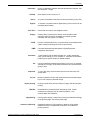
Related publications
The Xerox DocuPrint 180 Laser Printing System Forms Creation
Guide is part of the ten manual reference set for your laser printing
system. The entire reference set is listed in the table below. Several
other related documents are also listed for your convenience. For a
complete list and description of available Xerox documentation, refer
to the Xerox Documentation Catalog (Publication number
610P17417) or call the Xerox Documentation and Software Services
(XDSS) at 1-800-327-9753.
Table 1.
Related Publications
Publication
Number
Xerox DocuPrint 180 Laser Printing System Operator 721P85490
Guide
Xerox DocuPrint 180 Laser Printing System
Operations Reference
721P85500
Xerox DocuPrint 180 Laser Printing System
Message Guide
721P85550
Xerox DocuPrint 180 Laser Printing System PDL
Reference
721P85530
Xerox DocuPrint 180 Laser Printing System Forms
Creation Guide
721P85520
Xerox DocuPrint 180 Laser Printing System
System Generation Guide
721P85510
Xerox DocuPrint 180 Laser Printing System
Installation Planning Guide
721P85480
Xerox DocuPrint 180 Laser Printing System Operator 721P85560
Command Summary Card
Xerox DocuPrint 180 Laser Printing System PC UI
Reference
721P85540
Xerox DocuPrint 180 Laser Printing System Product 721P85570
Reference
Xerox Laser Printing Systems Tape Formats Manual 600P86175
Xerox Laser Printing Systems Standard Font Library 600P86174
Font User Guide
Helpful Facts About Paper
721P82492
Notice
This publication may contain descriptions of concepts and features
not currently available for your Xerox Laser Printing System. Consult
your Xerox sales representative or your operating system software
program description for additional information.
XEROX DOCUPRINT 180 LPS FORMS CREATION GUIDE
iii
iv
XEROX DOCUPRINT 180 LPS FORMS CREATION GUIDE
Table of Contents
Related publications
iii
Notice
iii
Introduction
1.
2.
ix
About the reference set
ix
DocuPrint 180 Laser Printing System document set
x
What this guide contains
xii
Conventions used in this guide
xiii
Overview
1-1
Laser printing technology
1-2
Paper
1-2
Fonts
1-3
Forms creation
1-3
Basic concepts
2-1
Page orientation
2-1
Fonts
2-2
Page frames
2-4
Physical page
2-4
System page
2-5
Virtual page
2-5
Form origin
2-6
Positioning form elements
Grids
2-8
x and y coordinate
2-8
Predefined formats
2-9
Data types
3.
2-6
2-11
Forms description language
3-1
FDL command overview
3-1
Command summary
3-2
Command format
3-3
Steps to creating a form
3-4
Setup commands
3-5
FORM command
3-5
PAPER command
3-6
Using B4 paper size
XEROX DOCUPRINT 180 LPS FORMS CREATION GUIDE
3-7
v
TABLE OF CONTENTS
Using B5 paper size
3-7
Specifying TAB as a form
3-8
LANDSCAPE/PORTRAIT command
3-9
GRID command
3-10
FONT command
3-14
Description commands
3-15
LINE command
3-16
Types of lines
4.
3-18
BOX command
3-21
TEXT commands
3-24
TEXT AT
3-24
Aligning text
3-26
TEXT IN BOX
3-31
TEXT IN BOX command defaults
3-32
LOGO command
3-36
GRAPHIC command
3-37
SECTION commands
3-38
COMMENT command
3-40
END command
3-41
Compiling and printing forms
4-1
Form printing processing
4-1
Creating an FSL form
4-1
Communicate the FSL file to the LPS system disk
4-2
Using magnetic tape
Compiling a form
5.
4-2
Invoking the forms compiler
4-2
Summary sheet
4-4
Error checking
4-4
PROOF option
4-5
Secured files
4-5
Debugging and modifying the file
4-6
Storing form files
4-7
Printing a compiled form
4-7
FDL compilation time
4-8
Forms layout considerations
5-1
Image complexity
5-1
Line tables
5-1
Importance of orderly construction
Scan line density
vi
4-2
5-2
5-4
XEROX DOCUPRINT 180 LPS FORMS CREATION GUIDE
TABLE OF CONTENTS
Page generation errors
5-5
Local density and page setup errors
5-6
Summary
5-7
Using boxes
5-8
Text in boxes
5-8
Locating the closest box
5-9
Shading
5-12
Sections
5-13
Rounding measurements
5-14
Converting other unit values to dots
5-14
Rounding variable data
5-15
Suggested coding techniques
Converting preprinted forms
5-16
Designing new forms
5-16
Recommended coding sequence
5-16
Syntax ambiguities
6.
5-16
Coding a complex form
5-18
6-1
Getting started
6-1
Writing the setup commands
6-2
Using the COMMENT command
6-2
Drawing lines
6-3
Drawing horizontal lines
6-3
Drawing vertical lines
6-3
Drawing boxes
6-4
Placing text at a location
6-5
Placing text in a box
6-6
END command
6-7
Compiling the form
A. FDL command summary
FDL command syntax
6-8
A-1
A-1
B. FDL-generated messages
B-1
C. System default summary
C-1
D. GRID and TEXT command examples
D-1
E. FDL capacity limits
E-1
F.
F-1
Support tools and measurements
Forms design ruler
XEROX DOCUPRINT 180 LPS FORMS CREATION GUIDE
F-1
vii
TABLE OF CONTENTS
Glossary
Index
viii
GLOSSARY-3
INDEX-1
XEROX DOCUPRINT 180 LPS FORMS CREATION GUIDE
Introduction
The DocuPrint 180 Laser Printing System Forms Creation Guide is
intended for forms designers who have a basic knowledge of the
DocuPrint 180 Laser Printing System (LPS). You may have received
on-site training, or you may have attended a Xerox FDL training
course.
The forms designer’s tasks consist of writing FDL commands to
produce electronic forms. These tasks include entering source code
into the LPS to create new electronic forms, as well as updating,
revising, and printing the forms on the LPS. If you are also
responsible for printing variable data on the forms in addition to
performing other operations on the laser printer, refer to the related
documents provided with your laser printing system.
The DocuPrint 180 Laser Printing System Forms Creation Guide is
one of eight manuals which make up the DocuPrint 180 LPS
Reference Set. This guide explains the use of Forms Description
Language (FDL) commands that are used to create forms. Its
purpose is to do the following:
•
Describe the FDL commands necessary to create any desired
form with the correct page orientation, fonts, line widths, and
positioning of captions and logos
•
•
Explain fundamental printing terms and techniques
Describe the use of support tools in simplifying the creation of
forms.
About the reference set
This document is part of a reference set designed to help you receive
maximum benefit from your DocuPrint 180 laser printing system.
To help you select the appropriate document for your needs, the
following section identifies the documents in the set and describes
the information contained in each.
XEROX DOCUPRINT 180 LPS FORMS CREATION GUIDE
ix
INTRODUCTION
DocuPrint 180 Laser Printing System document set
The DocuPrint 180 LPS document set includes the following:
DocuPrint 180 LPS Operator Guide
This reference contains the following information:
•
•
•
•
•
•
•
DocuPrint 180 LPS PDL Reference
DocuPrint 180 LPS Operations
Reference
DocuPrint 180 LPS Forms Creation
Guide
x
Paper facts and procedures
Operating procedures
Maintenance
Problem solving
Supplies
Meter reading and reporting
This reference contains the following information:
•
•
•
•
•
•
•
DocuPrint 180 LPS System Generation
Guide
System overview
Print Description Language components and processes
Input processing functions
Output processing functions
PDL command summary
Page formatting guidelines
Character code assignment tables
PDL programming information with step-by-step instructions
This reference contains the following information:
•
•
•
Configuration options
Commands
OSS software installation, upgrade, and modification
This reference contains the following information:
•
Command syntax for operator and system administrator
procedures
•
•
•
•
•
LPS defaults
LPS resources
Command summaries
Communication and graphics on the LPS
Command files
This reference contains the following information:
•
•
•
•
Basic concepts for creating forms
Coding and compiling for LPS Forms Description Language
Sample form setup command sets
Tips for successful forms creation
XEROX DOCUPRINT 180 LPS FORMS CREATION GUIDE
INTRODUCTION
DocuPrint 180 LPS Operator Command
Summary Card
DocuPrint 180 LPS Message Guide
This reference provides a quick reference of commonly-used
commands.
This reference contains the following information:
•
•
DocuPrint 180 LPS Installation
Planning Guide
DocuPrint 180 LPS PC UI Reference
•
•
•
•
•
Helpful Facts About Paper
Tasks that must be accomplished before installation
Preinstallation requirements
Installation process
Postinstallation activities
PC UI procedures
Hierarchy of PC UI windows
This reference contains the following information:
Product overview
Hardware and software
LPS connections
User considerations
LPS comparisons
This reference contains the following information:
•
•
•
•
DocuPrint 180 LPS Standard Font
Library Font User Guide
LPS basic components and options
This reference contains the following information:
•
•
•
•
•
Tape Formats Manual
Meaning and recovery procedures
This reference contains the following information:
•
•
DocuPrint 180 LPS Product Reference
OSS and other messages
Characteristics of different formats
File organization
Data formats
Carriage control conventions
This reference contains the following information:
•
Font naming conventions
•
•
•
Listing of standard fonts
Data Sheets
Glossary to typography terminology
This reference contains the following information:
•
•
•
XEROX DOCUPRINT 180 LPS FORMS CREATION GUIDE
Selection and guidelines
Storage
Specifications for different printers
xi
INTRODUCTION
What this guide contains
The DocuPrint 180 Laser Printing System Forms Creation Guide
shows how to create electronic forms by describing them in words
and numbers. FDL is not complicated; it requires performing a few
dimensional measurements and learning some easy-to-follow rules.
The guide is divided into six chapters and six appendices as follows:
Chapter 1: Overview. Contains an explanation of the general
functions and advantages of the Forms Description Language plus
an introduction to laser printing technology.
Chapter 2: Basic concepts. Explains the fundamental printing terms
and techniques that you need to know before starting to create a
form.
Chapter 3: Forms description language. Gives the name, function,
and detailed format of each FDL command that can be used in
setting up and describing a form.
Chapter 4: Compiling and printing forms. Explains how FDL source
code is compiled and stored on the system disk for printing.
Chapter 5: Forms layout considerations. Explains the ambiguities
and constraints inherent in the Forms Description Language.
Chapter 6: Coding a complex form. Gives the step-by-step
procedure for creating a sample form.
Appendix A: FDL command summary. Gives a format-only listing of
all the FDL commands described in this manual.
Appendix B: FDL-generated messages. Lists all the status and error
messages that may appear during compilation.
Appendix C: System default summary. Lists the system default
values that are automatically supplied when keywords are omitted
from the commands.
Appendix D: Hierarchy of grid unit scaling. Explains the system’s
defaults and overrides in response to various grid scaling
specifications.
Appendix E: FDL capacity limits. Describes the various maximums,
in terms of lines, buffers, and space allocation, imposed by the
memory space limits.
Appendix F: Support tools and measurements. Describes the forms
design ruler that is used to lay out and measure a form.
Glossary: Defines the technical terms used in the manual.
xii
XEROX DOCUPRINT 180 LPS FORMS CREATION GUIDE
INTRODUCTION
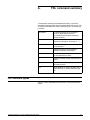
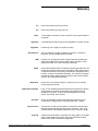
Conventions used in this guide
This guide uses the following conventions:
<>
Angle brackets are used for keys on the PC User Interface keyboard.
{ }
Braces indicate that one of the items stacked inside must be entered.
...
[ ]
|
bold
italics
TERMINAL FONT
underline
UPPERCASE
Ellipses indicate that you can repeat a parameter or list a series of
parameters.
Square brackets are used for optional command characters.
Vertical bars are used to separate parameters in a series. The
vertical bar stands for ”or.”
Bold is used for characters you enter at the command line.
Italics are used for variable information.
Terminal or monospace font is used to display system responses.
System default parameters are underlined.
Uppercase letters represent data that must be entered as shown;
however, a keyword may be abbreviated to the first three letters.
XEROX DOCUPRINT 180 LPS FORMS CREATION GUIDE
xiii
INTRODUCTION
xiv
XEROX DOCUPRINT 180 LPS FORMS CREATION GUIDE
1.
1Overview
The laser printing system (LPS) provides the capability to create
electronic forms tailored to meet your individual requirements. You
create electronic forms using Forms Description Language (FDL).
This simple-to-learn, easy-to-use language enables you to design
and alter forms in minutes. FDL eliminates the need for preprinted
forms and the expense of forms obsolescence. It also eliminates the
delays associated with stocking forms and overlays.
FDL-defined forms are input to the printer as data, using the LPS
keyboard and display, or a host computer terminal. To define a form,
FDL uses such elements as lines, logos, images, signatures,
shading, and different font styles and sizes to make full use of laser
printing system features and capabilities. FDL provides an easy and
quick means of achieving maximum visual impact and readability.
Advantages of FDL include the following:
•
Lines can be drawn at specified intervals without being redefined each time.
•
You have only to state the origin and the dimensions of a box to
have it drawn at any specified location on the page.
•
An entire section of a form, once defined, can be repeated
anywhere on the same form.
•
When defining a location on a page, you are not restricted to
lines and character positions. You can specify coordinates in
inches, centimeters, dots and xdots, with a resolution of 1/300
inch or 1/600 inch in either direction.
Note: An xdot is a 1/600 inch unit of measure that is provided with
version 3 software. A form specifying xdots may be created, edited,
and compiled on any V3-based LPS. However, results are
unpredictable if you attempt to print a 600 spot per inch (spi) form on
a 300 spi LPS.
•
Once forms have been created, they can be stored on the
system and printed—as many as you need and as often as you
need.
•
You can use three types of lines (solid, broken, or dotted) in
four thicknesses (invisible [0], hairline, medium [1], or bold [2]).
You can also mix fonts and arrange text in many ways, all with
simple FDL commands.
XEROX DOCUPRINT 180 LPS FORMS CREATION GUIDE
1-1
OVERVIEW
Laser printing technology
Before you learn about the actual forms creation process, an
introduction to the printing system will be helpful.
Xerox laser printing systems are sophisticated nonimpact printers
that use a combination of laser, digital, and xerographic technologies
for their imaging and printing processes. These advanced
technologies allow the LPS to avoid optical constraints such as form
overlays and limited character fonts. All control functions are carried
out electronically; the software commands requesting these
functions are given in keywords, phrases, or sentences.
A digitally controlled laser beam is directed at a photoreceptor belt to
create the xerographic image. The beam can be controlled with an
accuracy of 1/300 inch or 1/600 inch (depending upon the type of
system). This enables it to faithfully reproduce complex logos,
signatures, and virtually any desired font at a consistently high level
of quality.
Paper
The DocuPrint 180 can use a wide variety of paper sizes and types.
They are listed below:
Paper sizes
The DocuPrint 180 LPS prints on the following standard paper sizes:
•
•
•
•
•
•
8.5 by 11 inch (216 by 279 mm)
A4 (8.27 by 11.69 inch, 210 by 297 mm)
8.5 by 14 inch (216 by 356 mm)
A3 (16.54 by 11.69 inch, 420 by 297 mm)
B4 (10.12 by 14.33 inch, 257 by 364 mm)
B5 (7.17 by 10.12 inch, 178 by 254 mm)
x BY y specifies nonstandard sizes
Paper types
A large variety of paper types can also be used on all printing
systems:
•
•
•
•
•
Label stock
Transparencies
Predrilled
Perforated
Colored
Finished reports can be offset from one another in the output stacker
to permit easy separation.
1-2
XEROX DOCUPRINT 180 LPS FORMS CREATION GUIDE
OVERVIEW
Fonts
A set of standard LPS fonts are provided free of charge at installation
time. (Font is a publishing term referring to a set of characters with
the same type style, type size, and orientation.)
Note: Additional fonts, whether standard or custom designed, may
be special ordered from the Xerox Font Center or Xerox Limited. You
can also order digitized logos and signatures. Refer to your
DocuPrint 180 LPS Installation Planning Guide for information on
ordering fonts.
Printing at maximum density, the system can produce almost 40,000
characters per page. Moreover, laser printing systems can change
fonts at any time (for example, for captions, titles, and italicized
words) without interrupting or delaying the printing process. This fontswitching capability extends to fonts whose characters are turned 90
or 180 degrees from the normal character orientation. The system
also permits editorial changes, such as font changes and deletions,
to selected copies of a report.
Forms creation
You enter forms into the system as data, using straightforward,
descriptive terms and language. Forms are stored on a system disk
and are called when needed, providing nonstop operation. This
advanced concept has a decided advantage over systems that
require interruption of printing to change overlays and preprinted
forms. A large number of forms may be stored on disk, and multiple
forms may be loaded into forms memory for each job (the exact
number depends on the complexity of the forms). A form may be
used for all copies or selected copies of a report with each page
being produced as an original.
Since forms are created without overlays, transparencies, or
masters, there is no risk of misalignment, blurring, or scratch marks.
Forms are merged with the data stream from a host computer or
magnetic tape, ensuring perfect registration between form and data
each time the form is printed. Character splitting, line splitting, and
other precise positioning can be accomplished with complete
accuracy. In addition, laser printing systems provide flexibility not
previously feasible on impact printers.
FDL is easy to learn and easy to use. Whenever you choose to
redesign your form, a few simple commands enable you to
completely change the appearance and function of the form.
Modifications to existing electronic forms can be made easily and
inexpensively using the LPS editing facility or your own.
Take a moment to review the many LPS publications that are
available. They are listed in the front of this guide under “Related
publications.” These documents are designed to assist you in making
the most effective use of your LPS. They include a complete
reference set that discusses the functional characteristics of your
LPS and provide helpful information to assist the LPS Operator,
System Administrator, and Programmer.
XEROX DOCUPRINT 180 LPS FORMS CREATION GUIDE
1-3
OVERVIEW
1-4
XEROX DOCUPRINT 180 LPS FORMS CREATION GUIDE
2.
2Basic concepts
Certain basic concepts are required to understand the forms creation
process on laser printing systems. These involve the size, shape,
and location of the overall image on the page of a document, the
orientation of the text or graphics on the page, the size and style of
the characters to be used, and the type of data to be entered.
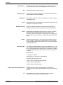
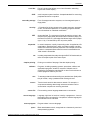
Page orientation
There are two types of page, or text orientation:
•
•
Portrait page
Landscape page
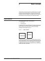
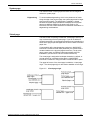
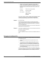
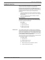
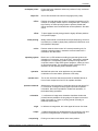
In portrait orientation, the vertical side of the page is longer than the
horizontal side. In landscape orientation, the horizontal side of the
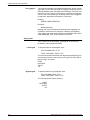
page is longer than the vertical side. Portrait and landscape
orientations are illustrated in figure 2-1.
Figure 2-1.
Page orientation
PORTRAIT
LANDSCAPE
Landscape is the usual orientation for computer reports. Portrait is
the usual orientation for letters, manuals, and other text printing. On
a laser printing system, you can change page orientation from page
to page without interrupting the printing operation. This capability,
coupled with variable character size, permits maximum flexibility for
effective information presentation.
XEROX DOCUPRINT 180 LPS FORMS CREATION GUIDE
2-1
BASIC CONCEPTS
Fonts
Fonts are character sets, each having a unique type style, type size,
and orientation.
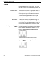
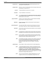
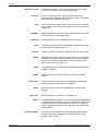
Fixed and proportional spacing
Fixed and proportionally spaced fonts are available for use on laser
printing systems. Each character occupies an area on the form called
a character cell. With fixed fonts, all character cells in the set are the
same width. With proportional fonts, character cells vary in width, as
shown in figure 2-2.
Figure 2-2.
Character spacing
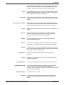
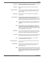
Because the length of a line printed with a proportional font is
relatively unpredictable, fixed fonts are used for variable data on a
report to avoid overprinting forms data with variable data.
Proportional fonts are normally used for forms data, that is, titles,
headings, and so forth. A letter is an example of the use of
proportional fonts for variable data. The differences in width are
illustrated in figure 2-3.
Figure 2-3.
Character spacing examples
Fonts are available in various typefaces (for example, OCR and
Titan), sizes, styles (for example, serif and sans serif), and weights
(for example, medium and bold). For specific font size information,
refer to your DocuPrint 180 LPS Product Reference.
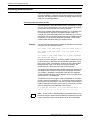
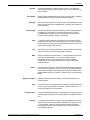
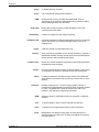
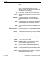
Font orientation
In addition to typeface, style, and size, the font can be defined by its
orientation:
•
•
•
•
Landscape
Portrait
Inverse landscape
Inverse portrait
The font orientation, as shown in figure 2-4, is relative to the physical
page.
2-2
XEROX DOCUPRINT 180 LPS FORMS CREATION GUIDE
BASIC CONCEPTS
Figure 2-4.
Font orientation
Note that even though type style and size are the same, four different
fonts are used, each with a unique orientation. The inverse portrait
font could be used for certain types of titles or labels on a landscape
form. Conversely, the inverse landscape font could be used for titles
on a portrait form.
The Xerox Laser Printing Systems Standard Font Library Font User
Guide and the Xerox 4850 HighLight Color and 4135 Laser Printing
Systems Font User Guide (refer to the “Related publications” section
of this guide) list the standard fixed and proportional fonts provided
with the LPS. Special fonts not included in the standard font library
may be ordered from the Xerox Font Center or Xerox Limited. (Refer
to your DocuPrint 180 LPS Installation Planning Guide for
information on ordering fonts.)
XEROX DOCUPRINT 180 LPS FORMS CREATION GUIDE
2-3
BASIC CONCEPTS
Page frames
A page frame is a set of boundaries associated with a page as a unit
of printing or imaging. Three page frames are defined in this guide:
•
•
•
Physical page
System page
Virtual page
Physical page
The paper on which a form is printed is the “physical page.” The
default paper size used on an LPS is defined during system
generation (sysgen). The following paper sizes may be specified:
•
•
•
•
•
•
•
•
•
•
•
•
•
•
•
•
•
8.5 by 11 inches (USLETTER, 216 by 279 mm)
8.5 by 14 inches (USLEGAL, 216 by 356 mm)
8.27 by 11.69 inches (A4, 297 by 270 mm)
16.54 by 11.69 inches (A3, 297 by 420 mm)
10.12 by 14.33 inches (B4,257 by 364 mm)
7.17 by 10.12 inch (B5, 178 by 254 mm)
8.0 by 10.02 inches (203 by 254 mm)
8.0 by 10.5 inches (203 by 266 mm)
8.0 by 13.0 inches (203 by 330 mm)
8.27 by 10.63 inches (210 by 270 mm)
8.27 by 13.0 inches (210 by 330 mm)
8.37 by 10.78 inches (212 by 273 mm)
8.46 by 10.83 inches (214 by 275 mm)
8.46 by 12.40 inches (214 by 314 mm)
8.46 by 14.02 inches (214 by 356 mm)
8.50 by 10.75 inches (215 by 273 mm)
8.50 by 13.0 inches (215 by 330 mm)
The DocuPrint 180 supports the 11 by 17-inch and 16.54 by 11.69inch sizes as sysgen options.
The PAPER command may be used to identify the paper size. If it is
not present, the sysgen value is assumed.
When variable data is to be merged with a form, the paper size for
both must match and the correct size paper must be loaded.
2-4
XEROX DOCUPRINT 180 LPS FORMS CREATION GUIDE
BASIC CONCEPTS
System page
The maximum area in which graphics and text can be imaged is
called the “system page.”
Edgemarking
To accommodate edgemarking, which is the placement of marks
along the edge of the physical page, the system page must be larger
than the physical page. The edgemarking capability is limited
because the system page boundaries correspond to the physical
page on at least two edges for all paper sizes. Refer to your
DocuPrint 180 LPS Product Reference for additional information on
edgemarking considerations.
Virtual page
The area chosen for printing is called the “virtual page” and may or
may not be as large as the system page. If you do not define its
dimensions explicitly, the virtual page dimensions are, by default, the
same as the sysgen-specified paper size or as the PAPER command
paper size.
If you explicitly define virtual page size (using the LANDSCAPE/
PORTRAIT command PAGE SIZE parameter), the defined area is
centered relative to the physical page dimensions. (The physical
page, system page, and defined virtual page relationships are
illustrated in your DocuPrint 180 LPS Product Reference.)
The virtual page is assigned a landscape orientation by default, or
you can specify an orientation either with the LANDSCAPE/
PORTRAIT command or using the GRID command's FMTn option.
The upper left corner of the virtual page is called the “virtual page
origin.” The virtual page origin is also used to establish a form origin.
Figure 2-5.
XEROX DOCUPRINT 180 LPS FORMS CREATION GUIDE
Virtual page origin
2-5
BASIC CONCEPTS
Form origin
All forms data described by FDL commands is positioned relative to
a point called the “form origin.” This point is offset from the virtual
page corner by horizontal and vertical displacement values, which
you specify using the GRID command. If none are specified,
standard default values are used to establish the form origin.
If variable data is merged with the form, the form origin should
generally be set to coincide with the beginning position of the variable
data so the form and variable data coordinate accurately. Standard
computer printing formats are stored on the system. Refer to the
“Predefined formats” section later in this chapter.
Figure 2-6.
Form origin
Positioning form elements
Elements that may be placed on a form with FDL commands are the
following:
•
•
•
•
•
•
Lines
Boxes
Fixed text
Logos and signatures
Images
Sections
All of these elements are located in relation to the form origin at the
upper left corner of the form. Each form element has an origin, a point
used to position it relative to the form origin.
2-6
XEROX DOCUPRINT 180 LPS FORMS CREATION GUIDE
BASIC CONCEPTS
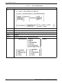
Table 2-1.
Form element origin
Form element
Element origin
Vertical ruled line
Top of the line at midpoint of line thickness
Horizontal ruled line
Left end of the line at midpoint of line thickness
Box (outlined)
Upper left corner of the box at the midpoint of the outline
thickness
Box (shaded)
Upper left corner of the box
Fixed text (single
line)
Upper left corner of the first character cell with the line upright
to the viewer
Fixed text (multiple
lines)
Upper edge of the topmost character cell and the leftmost edge
of the leftmost character cell when viewed in a upright position
Graphics
Upper left corner of the image
logos and signatures
Upper left corner of the first (or only) character cell (with
exceptions)
Sections (of a form)
Upper left corner of the section
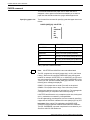
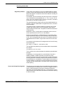
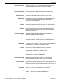
The following symbol in figure 2- 7 shows where the text block origin
is located.
Figure 2-7.
Text block origin symbol
Figure 2-8 shows two text blocks, one using a portrait font and one
using a landscape font.
This is the point used to position the text block relative to the form
origin.
Figure 2-8.
XEROX DOCUPRINT 180 LPS FORMS CREATION GUIDE
Text block origin
2-7
BASIC CONCEPTS
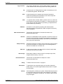
Grids
The location of a form element on a page is specified in terms of its
horizontal and vertical displacement from the form origin. The units
of measurement used to define this displacement can be the
following:
•
•
•
•
Linear units—inches or centimeters
Dots—300 per inch
Xdots—600 per inch
Cpi and lpi—(characters per inch horizontally and lines per inch
vertically)
x and y coordinate
The y coordinate describes the vertical position on a grid. The x
coordinate describes the horizontal position. When both coordinates
are given together, the y coordinate is always specified first.
If you draw a horizontal and a vertical line through the form origin to
create x and y coordinates, you would express the location of the
form origin as y=0, x=0.
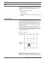
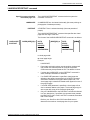
If you draw more lines to mark horizontal and vertical measurements
away from the form origin so that the lines were one unit of
measurement apart, you create a grid like the one shown in figure
2-9. You can then position form elements (lines, boxes, and so on)
by specifying a grid location.
Figure 2-9.
Form grid
Example: You placed the letter “A” at location (2,1). If you are
measuring grid units in inches, the origin of the “A” character cell is
located two inches down and one inch to the right of the form origin.
2-8
XEROX DOCUPRINT 180 LPS FORMS CREATION GUIDE
BASIC CONCEPTS
If you are measuring the grid in cpi and lpi units, the origin of the “A”
character cell is located two lines down and one character width to
the right of the form origin. At 10 cpi and 6 lpi, the “A” is .33 inch down
from the form origin and .10 inch to the right.
Negative coordinates
Negative x and y values also may be used to place form elements
above and or to the left of the form origin, as long as the values are
within system page boundaries.
UNIT value
The unit value of the GRID command specifies the unit of
measurement FDL commands use to position form elements on the
page. Optionally, you can select a predefined format that
automatically provides grid unit values. Individual FDL commands
may override GRID unit values.
Predefined formats
A set of predefined print description entries or formats, having
standard format specifications, are provided on the operating system
software (OSS) tapes. You may use these standard print formats or
define your own to suit your specific needs. These standard formats
provide commonly used impact printer conversion formats for use
with specific page sizes and orientations. Use the Xerox Design
Ruler to assist you in measuring character and line spacing. The ruler
has eight scales that conform to the standard format grid. (Refer to
table F-1.)
FMT1 (landscape) or FMT6 (portrait) is used by FDL to provide
default values for page orientation, form origin, and grid unit
dimensions, provided there are no explicit overriding parameters.
Note: Unless overridden by an explicit orientation PAGE SIZE
parameter, the virtual page size in a predefined format is always the
sysgen-specified paper size. The virtual page origin is located at the
upper left corner of the physical page.
XEROX DOCUPRINT 180 LPS FORMS CREATION GUIDE
2-9
BASIC CONCEPTS
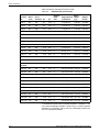
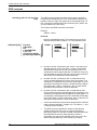
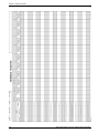
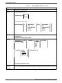
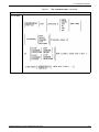
Table 2-2 lists the standard LPS print formats.
Table 2-2.
Standard LPS print formats
cpi
Approx.
point
size
Begin
Page size and values
orientation*
(y,x)
Default
font ID
8.1
13.6
9
11 by 8.5 in
(.18,.66)
L0112B
150
8.1
15.0
9
11 by 8.5 in
(.18,.50)
L0212A
88
132
10.7
13.6
7
11 by 8.5 in
(.14,.66)
L0312A
FMT4
88
150
10.7
15.0
7
11 by 8.5 in
(.14,.50)
L0412A
FMT5
49
100
6.0
10.0
12
11 by 8.5 in
(.17,.50)
L0512A
FMT6
80
100
8.1
13.6
9
8.5 by 11 in
(.57,.58)
P0612A
FMT7
60
90
6.0
12.0
12
8.5 by 11 in
(.50,.50)
P07TYA
FMT8
60
75
6.0
10.0
12
8.5 by 11 in
(.50,.50)
P0812A
FMT9
80
200
10.0
20.0
7
11 by 8.5 in
(.25,.25)
L0912A
FMT10
132
132
12.5
17.6
6
8.5 by 11 in
(.22,.51)
P1012A
FMT11
132
150
12.5
20.0
6
8.5 by 11 in
(.22,.50)
P1112A
FMT12
66
172
8.1
13.6
9
14 by 8.5 in
(.18,.66)
L0112B
FMT13
104
100
8.1
13.6
9
8.5 by 14 in
(.57,.58)
P0612A
FMT1A
66
132
8.3
12.5
9
297 by 210 mm (.18,.57)
R112BL
FMT2A
66
150
8.3
14.3
9
297 by 210 mm (.18,.60)
R212BL
FMT3A
88
132
11.1
12.5
7
297 by 210 mm (.18,.57)
R312BL
FMT4A
88
150
11.1
14.3
7
297 by 210 mm (.18,.60)
R412BL
FMT5A
48
100
6.0
10.0
12
297 by 210 mm (.22,.85)
R512BL
FMT6A
80
100
8.1
13.6
9
210 by 297 mm (.91,.46)
R612BP
FMT7A
60
90
6.0
12.0
12
210 by 297 mm (.85,.39)
R7TIBP
FMT8A
60
75
6.0
10.0
12
210 by 297 mm (.85,.39)
R812BP
FMT9A
80
200
10.0
20.0
7
297 by 210 mm (.14,.85)
R912BL
FMT10A 132
132
12.5
17.6
6
210 by 297 mm (.57,.39)
RA12BP
FMT11A 132
150
12.5
20.0
6
210 by 297 mm (.57,.39)
RB12BP
Format
ID
No of
lines
No of
columns Ipi
FMT1
66
132
FMT2
66
FMT3
A4
formats
* First dimension given is the horizontal dimension. Therefore, 11 by
8.5 inches is landscape orientation, while 8.5 by 11 inches is portrait
orientation. For A4 paper, 297 by 210 mm is landscape, and 210 by
297 mm is portrait orientation.
2-10
XEROX DOCUPRINT 180 LPS FORMS CREATION GUIDE
BASIC CONCEPTS
Data types
Two types of data are used in LPS forms creating and printing:
•
•
Variable data
Forms data
The term “variable data” generally refers to computer produced
information that the LPS merges with a form. Typically this data
varies from page to page.
The term “forms data” refers to information that is used to print the
form, such as lines between columns and rows, boxes, and shading.
Forms data also refers to information that is part of the form such as
titles, headings, captions, logos, and signatures. Forms data typically
does not vary from page to page.
XEROX DOCUPRINT 180 LPS FORMS CREATION GUIDE
2-11
BASIC CONCEPTS
2-12
XEROX DOCUPRINT 180 LPS FORMS CREATION GUIDE
3.
3Forms description language
This chapter describes the function and use of each forms
description language (FDL) command in generating a form
electronically.
FDL command overview
FDL is a set of keyword commands that you can use to generate an
electronic form. To do this, you create a source file of FDL commands
that describes the characteristics of your form. The form can contain
a variety of fonts, logos and graphics, and it can be merged with
variable data during printing. This file is then compiled and stored as
an electronic form file on the LPS printer. You can select any stored
form for printing.
XEROX DOCUPRINT 180 LPS FORMS CREATION GUIDE
3-1
FORMS DESCRIPTION LANGUAGE
Command summary
The following commands are available for creating a form:
FORM /RESOLUTION
PAPER
LANDSCAPE/PORTRAIT
Identifies the name of a form in the forms library and the resolution at
which the form should be compiled for printing.
Identifies the paper size for which the form is designed.
Specifies page orientation and virtual page size.
GRID
Specifies the grid units used in describing the form and the origin of
the form relative to the virtual page origin. In most cases, a standard
format specification can be entered, which provides standard
character and line spacing, page orientation, and form origin.
FONT
Specifies which fonts to use when creating a form.
LINE
Specifies length, position, direction, and thickness (hairline, 0, 1, or
2) of lines.
BOX
Specifies location of upper left corner and dimensions of square or
rectangular boxes. All boxes in FDL are fixed-size. Backgrounds for
text must use the BOX command.
TEXT
LOGO
Specifies text (written matter) such as form titles, headings, and
labels.
Specifies the positioning of logos and signatures.
GRAPHIC
Specifies a graphic image to be merged with the form and its
placement and relative scale.
SECTION
Defines a portion of a form as a relocatable section.
END SECTION
DO SECTION
COMMENT
END
Terminates a section.
Invokes and places a previously defined section of a form.
Inserts comments.
Terminates a form description.
The “FDL command summary” appendix contains a complete list of
FDL command formats. Each format is explained separately later in
this chapter.
3-2
XEROX DOCUPRINT 180 LPS FORMS CREATION GUIDE
FORMS DESCRIPTION LANGUAGE
Command format
The following is true for each FDL command:
•
The command consists of a command identifier and various
parameters and keywords associated with the function.
•
•
•
Spaces or commas separate keywords and parameters.
•
Multiple commands may appear in one record if separated by a
semicolon.
•
Commands can be continued on multiple lines before ending
with a semicolon, with the exception of the LINE and BOX
command. For both these commands, the string
A command is terminated by a semicolon.
Command information is placed within the first 72 columns of
each record.
AT . . . IN [unit]
must reside in one line. Lines containing all blanks are ignored
and may, therefore, be used for separation.
XEROX DOCUPRINT 180 LPS FORMS CREATION GUIDE
3-3
FORMS DESCRIPTION LANGUAGE
Steps to creating a form
There are three basic steps required to produce an electronic form:
1. Initiate an editing session.
2. Enter the FDL commands.
3. Compile and print the form.
Initiating an editing session
The editor utility is used to create and modify your forms source
library (FSL) source files.
If you use your host editor utility, follow the instructions provided in
your host documentation.
If you use the LPS editor, refer to your DocuPrint 180 LPS Operations
Reference for detailed instructions.
Entering the FDL commands
There are five basic setup commands that specify the parameters in
which the form is described. Beginning at the first line of your source
file, enter the setup commands in the following order:
1. FORM
2. PAPER
3. LANDSCAPE/PORTRAIT
4. GRID
5. FONT
These setup commands precede the form description commands
which include:
Compiling and printing the form
3-4
After you have entered all the FDL commands needed to describe
your form, exit the editing session and invoke the forms compiler.
The “Compiling and printing forms” chapter explains how to compile
and print your form.
XEROX DOCUPRINT 180 LPS FORMS CREATION GUIDE
FORMS DESCRIPTION LANGUAGE
Setup commands
Before entering commands to describe a form, enter the setup
commands to specify the following:
•
•
•
•
•
FORM command
PAPER command
LANDSCAPE/PORTRAIT command
GRID command
FONT command
Of the setup commands, only the FORM command is always
required. The others are optional. (If they are not defined, the
defaults are used.) The FONT command is also required if text is to
be included on the form.
FORM command
The FORM command defines the name of the form. Once the form is
compiled and stored on the system disk, this is the name used by the
LPS software to reference the form.
The FORM command must be the first command in the form
definition and must be completely contained in the first record of the
form definition.
Naming the form
The FORM id portion is mandatory. The format is as follows:
FORM id;
The “id” portion is a one- to six-character identifier that references
the form. Reserved words (for example, FORM, GRID, FONT, TEXT,
BOX, LOGO, and so forth) cannot be used for the id. However,
reserved words can be appended and used as the id; for example,
FORM1, FORM2, and so forth.
Example:
FORM 3BOXES;
XEROX DOCUPRINT 180 LPS FORMS CREATION GUIDE
3-5
FORMS DESCRIPTION LANGUAGE
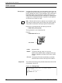
PAPER command
This command identifies the paper size for which the form is
designed. It is an optional command that enables you to select a
paper size that is different than the sysgen-defined paper size.
Specifying paper size
The format of the command for specifying standard paper sizes is as
follows:
PAPER [SIZE] [IS] USLETTER
;
A4
USLEGAL
A3
B4
B5
x BY y
OPTION
DESCRIPTION
USLETTER
8.5 by 11 inches (216 by 279 mm)
A4
8.27 by 11.69 inches (210 by 279 mm)
USLEGAL
8.5 by 14 inches (216 by 356 mm)
A3
16.54 by 11.69 inches (420 by 297 mm)
B4
10.12 by 14.33 inches (257 by 364 mm)
B5
7.17 by 10.12 inches (178 by 254 mm)
x BY y specifies nonstandard sizes
Note:
USLETTER and USLEGAL cannot be abbreviated.
The PDL programmer can specify paper size in a JSL (Job Source
Library). When the JSL specifies PAPERSIZE using the keyword
method, for example, USLETTER, A4, or USLEGAL, the FSL must
also use the same method. If the JSL specifies PAPERSIZE=8.5 by
14 and your FSL specifies PAPER [SIZE] [IS] USLEGAL, one of the
following error message is displayed:
OS6670 Form paper size too small. Form will not be printed.
OS6680 Form paper size too large. Form will not be printed.
These errors appear only when you print the form. The messages do
not appear when you compile the form without printing it.
USLETTER and B4 are the only exceptions to this rule; the keyword
and x,y method do not create any incompatibilities.
Due to edgemarking considerations, the form created by specifying
a paper size of USLEGAL is different from one specifying 8.5 by 14.0.
Important: When coding FSL applications, the PAPER SIZE
command must precede the LANDSCAPE/PORTRAIT statement.
The PDL PAPERSIZE command is explained in more detail in your
DocuPrint 180 LPS PDL Reference.
3-6
XEROX DOCUPRINT 180 LPS FORMS CREATION GUIDE
FORMS DESCRIPTION LANGUAGE
Using B4 paper size
When B4 size paper is specified in centimeters, the value should be
rounded off to 25.71 CM. This is only necessary when your GRID
statement is GRID [UNIT] [IS] INCHES.
Using B5 paper size
B5 (7.17 by 10.12 inch) paper size capability is an option which
requires a retrofit kit. When any paper size of less than the minimum
(7.17 by 10 inches) or greater than the maximum (17 by 14.33
inches) is specified in the FSL, the form does not compile and the
following error message appears:
Invalid paper size
When no paper size is specified
When there is no PAPER [SIZE] command specified in the FSL, the
DocuPrint 180 uses the sysgened paper size as the default. The
sysgen process does not check for the minimum nor the maximum
paper size. Therefore, if you sysgen the DocuPrint 180 with less than
the minimum or greater than the maximum paper size than its IOT
can support, the DocuPrint 180 compares the sysgened paper size
to the IOT-supported minimum/maximum paper size and if the
sysgened paper size is out of the IOT-supported minimum/maximum
paper size range, the following error message appears:
Sysgened paper size is out of range
Loading unsupported paper sizes
If an FRM file specifies a paper size that is not supported by the IOT,
the DocuPrint 180 aborts the job before any printing takes place and
displays the following error message:
Invalid paper size
XEROX DOCUPRINT 180 LPS FORMS CREATION GUIDE
3-7
FORMS DESCRIPTION LANGUAGE
Specifying TAB as a form
To define a form to be used as a tab, specify the following:
PAPER [SIZE] [IS] 9 BY 11;
Refer to your DocuPrint 180 LPS PDL Reference for a detailed
explanation of the Ordered and Tab Stock feature.
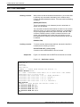
Specifying non-standard sizes
PAPER
The format of the command for specifying nonstandard paper sizes
is as follows:
[SIZE]
x
INCHES
CM
CENTIMETERS
DOTS
XDOTS
[BY] y
INCHES
CM
CENTIMETERS
DOTS
XDOTS
The x and y represent the decimal paper size that may be specified
if a form is to be printed on nonstandard size paper. Units are
optional. The default is inches.
Example:
PAPER SIZE IS USLETTER;
The DocuPrint 180 supports paper sizes of up to 17 by 14.33 inches
by implementing a Short Edge Feed (SEF) scheme. SEF refers to the
direction the paper is fed when using paper sizes larger than 14.33
inches in length. This feature enables you to print paper size up to 17
by 14.33 inches while retaining the current definition of landscape
and portrait orientation. Refer to your DocuPrint 180 LPS Operations
Reference for additional information on the SEF capability.
With predefined formats
If a predefined format is specified in the GRID command, paper size
is determined automatically, and the PAPER command is
unnecessary. The PAPER command is required, however, any time
the paper size is different from the sysgen default.
Default paper size
If no PAPER command is present, and no predefined format is
specified, the sysgen-defined paper size in effect at run time is used
as the form’s paper size value.
Caution: The correct size paper must be loaded in the feeder. A
paper size mismatch at run time causes an error message to be
displayed. The form does not print, and the job may be aborted.
3-8
XEROX DOCUPRINT 180 LPS FORMS CREATION GUIDE
FORMS DESCRIPTION LANGUAGE
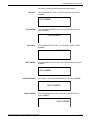
LANDSCAPE/PORTRAIT command
Specifying page orientation
and virtual page size
LANDSCAPE
PORTRAIT
The LANDSCAPE/PORTRAIT command tells the system the
orientation of the form.
A LANDSCAPE form is oriented horizontally (like most paintings or
photographs of landscape scenes).
A PORTRAIT form is oriented vertically (like most portraits of
people).
The LANDSCAPE/PORTRAIT command also specifies the virtual
page size and origin of the form.
The format of the LANDSCAPE/PORTRAIT command is as follows:
LANDSCAPE
PORTRAIT
PAPER [SIZE] [IS] n
DOTS
XDOTS
INCH[ES]
CM
CENTIMETERS
[WIDE][BY] m
DOTS
XDOTS
INCH[ES]
CM
CENTIMETERS
[HIGH]
;
n virtual page width
m virtual page height
Example:
LANDSCAPE;
•
Page width and height values must be positive numbers and
may contain two decimal places for all units except dots.
Centimeters may be expressed as CM. The default is inches.
•
If neither the LANDSCAPE nor the PORTRAIT command is
used, landscape orientation is assumed.
•
If no PAGE SIZE parameter is specified, virtual page size
defaults to the paper size specified in the PAPER command;
otherwise it defaults to the sysgen-defined paper size. The
virtual page origin is therefore located at the upper left corner of
the physical page.
•
If a PAGE SIZE parameter is specified, a virtual page of that
size is centered relative to the paper. The virtual page origin is
at the upper left corner of the centered virtual page.
•
Only one LANDSCAPE or the PORTRAIT command is allowed
in a form description. If specified, the command must precede
the GRID, BOX, LINE, LOGO, and TEXT commands, described
later in this chapter.
Refer to your DocuPrint 180 LPS Product Reference to
determine the maximum virtual page size for your system.
XEROX DOCUPRINT 180 LPS FORMS CREATION GUIDE
3-9
FORMS DESCRIPTION LANGUAGE
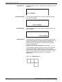
GRID command
Specifying grid unit size and form
origin
The GRID command tells the system how far apart to space the
horizontal and vertical grid lines. This command also specifies the
location of the form origin with respect to the virtual page origin. All
FDL commands create and place form elements (lines, boxes, and
so forth) relative to the form origin.
The format of the GRID command is as follows:
Example:
GRID IS 1 INCH;
format-id
Name of a predefined format. The format may be one of the
standard formats listed in table 2-1 or a user-defined format.
GRID [UNIT] [IS]
3-10
format-id
n INCH[ES]
CM
n CENTIMETERS
n CPI n LPI
[n] DOTS [[n] DOTS]
[n] XDOTS [[n] XDOTS]
ORIGIN
INCH[ES]
CM
CENTIMETERS
DOTS
XDOTS
x
INCH[ES]
CM
CENTIMETERS
DOTS
XDOTS
;
n
Number of inches, centimeters, dots, xdots, or cpi and lpi that
specifies the size of a grid unit. Size in inches or centimeters
represents the length of one side of a square grid unit. If n is
omitted when dots or xdots is specified, 1 is assumed. If only one
dots parameter is specified, the grid unit is the same number of
dots in both the horizontal and vertical dimension.
y
Number of inches, centimeters, dots, or xdots that the form
origin is offset downward from the top of the virtual page. The
coordinate y=0 represents the top of the virtual page. If y is not
specified, the top edge of the form is located at the top edge of
the virtual page. If inches, centimeters, dots, or xdots are not
specified in this parameter, inches are assumed.
x
Number of inches, centimeters, dots, or xdots that the form
origin is offset to the right of the left edge of the virtual page. The
coordinate x=0 represents the left edge of the virtual page. If x is
not specified, the left edge of the form is located at the left edge
of the virtual page. If inches, centimeters, dots, or xdots are not
specified in this parameter, inches are assumed.
•
Inches and centimeters may have two decimal places. Dots and
xdots must be expressed in integers only. The values n, y, and
x must be positive numbers.
•
The GRID command specified in number of dots allows a
greater flexibility than the more conventional methods of
specifying the grid. For example, instead of being limited to two
decimal places of accuracy when specifying inches or
centimeters, the grid can be specified to the dot or xdot. This
feature also eliminates any errors caused by rounding.
XEROX DOCUPRINT 180 LPS FORMS CREATION GUIDE
FORMS DESCRIPTION LANGUAGE
•
The GRID command may specify the name of a format, which
automatically provides page orientation, form origin, and grid
unit dimensions. (Refer to table 2-1.) All predefined formats
specify the grid units in lines and characters per inch. The
predefined format’s BEGIN values are used to place the form
origin, unless overridden by an ORIGIN parameter.
•
If the GRID command specifies explicit unit parameters and no
ORIGIN is specified, form origin coincides with virtual page
origin. If no grid units or predefined format are specified, FMT1
(landscape) or FMT6 (portrait) values are used by default.
•
Grid unit dimensions may be overridden by the BOX, LINE,
LOGO, and TEXT commands. Multiple GRID commands may
be used within a set of FDL commands. A GRID command
remains in effect until another is encountered.
The following examples illustrate how virtual page and form origin are
determined. (Also refer to the “Grids” section in the “Basic concepts”
chapter.)
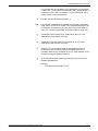
Example 1
LANDSCAPE;
GRID [UNIT] [IS] FMT3;
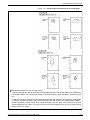
Figure 3-1 shows a form with the grid specified, but no page size or
origin.
Figure 3-1.
Form with grid specified, but no page size or origin
In example 1, no page size is specified, so the virtual page defaults
to paper size. FMT3 in the GRID command provides the grid size and
form origin (which is offset from the virtual page origin).
XEROX DOCUPRINT 180 LPS FORMS CREATION GUIDE
3-11
FORMS DESCRIPTION LANGUAGE
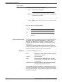
Example 2
LANDSCAPE;
GRID [UNIT] [IS] FMT1 ORIGIN 1 INCH 1 INCH;
Figure 3-2 shows a form with the origin offset one inch from the virtual
page origin.
Figure 3-2.
Form with origin offset one inch from virtual page
origin
In example 2, the ORIGIN parameter in the GRID command specifies
a form origin that is offset from the virtual page origin by one inch
vertically and one inch horizontally. Grid unit dimensions are set by
FMT1.
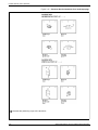
Example 3
LANDSCAPE PAGE SIZE IS 3 INCH 3 INCH;
Figure 3-3 shows a form with the page size specified, but not the
origin or grid.
Figure 3-3.
Form with page size specified, but no origin or grid
In example 3, the landscape-oriented virtual page is centered on the
paper in accordance with the parameters in the LANDSCAPE PAGE
SIZE command. Grid size and form origin default to FMT1.
3-12
XEROX DOCUPRINT 180 LPS FORMS CREATION GUIDE
FORMS DESCRIPTION LANGUAGE
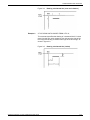
Example 4
LANDSCAPE PAGE SIZE IS 3 INCH 3 INCH;
GRID [UNIT] [IS] 1 CM;
Figure 3-4 shows a form with the grid specified, but not the origin or
format.
Figure 3-4.
Form with grid specified, but no origin or format
In example 4, explicit grid unit dimensions are set by the GRID
command, and no ORIGIN parameter or predefined format is
specified. This causes the form origin to be set to coincide with virtual
page origin.
Example 5
LANDSCAPE PAGE SIZE IS 3 INCH 3 INCH;
GRID [UNIT] [IS] FMT3;
Figure 3-5 shows a form with the grid and page size specified.
Figure 3-5.
Form with grid and page size specified
In example 5, FMT3 provides both the grid unit dimensions and form
origin.
XEROX DOCUPRINT 180 LPS FORMS CREATION GUIDE
3-13
FORMS DESCRIPTION LANGUAGE
Example 6
LANDSCAPE PAGE SIZE IS 3 INCH 3 INCH;
GRID [UNIT] [IS] FMT1 ORIGIN 1 INCH 1 INCH;
Figure 3-6 shows a form with the grid, origin, and page size specified.
Figure 3-6.
Form with grid, origin, and page size specified
In example 6, the location of the virtual page origin is determined by
the PAGE SIZE command. The form origin is offset from the virtual
page origin by one inch vertically and one inch horizontally.
FONT command
Specifying fonts
The FONT command identifies the character sets to use when
creating and printing forms data and variable data. Fonts must be
selected using the FONT command before text can be specified.
FONT can be used only once. The command has the following
format:
FONT [S] id[. . . id];
id
Identifier of the standard or custom font you want to use. The number
of fonts that can be specified depends on their size, the number of
fonts used in the variable data, and the size of font memory in your
system. However, the maximum number of fonts and logos allowed
per form by the forms compiler is 32.
Note:
Multiple ids are separated by either a blank or comma.
Example:
FONTS UN106A,UN104C,UN114A;
3-14
XEROX DOCUPRINT 180 LPS FORMS CREATION GUIDE
FORMS DESCRIPTION LANGUAGE
Description commands
The description commands specify the location, size, and
characteristics of the form elements: lines, boxes, logos, graphics,
form sections, and text.
The commands used for entering descriptive form data are:
•
•
•
•
•
•
LINE
BOX
TEXT AT
TEXT IN BOX
LOGO
GRAPHIC
These commands may be entered in any sequence. (For a
discussion of problems you may encounter when entering these
commands, refer to the “Forms layout considerations” chapter.)
Location coordinates
The locations are specified in terms of the y and x axis coordinates,
measured from the form origin specified in the GRID command.
Generally the form origin is set to coincide with the variable data
origin, and the grid units correspond to the character and line spacing
of the variable data. The form origin coordinates are specified as y=0,
x=0.
Both x and y coordinates may be given, or just one coordinate along
the y or x axis. If only one coordinate is given, the axis is implied in
the command.
Symbols for coordinates
Five symbols are used in the description commands to symbolize
different coordinates, as follows:
co
Origin coordinate
cs
Start coordinate
ce
End coordinate
ca
Absolute coordinate
ci
Incremental coordinate
The coordinate parameter may be followed by the unit of
measurement: inches (IN), centimeters (CM), or DOTS. If units of
measurement are not given in the command, the coordinates are in
grid units.
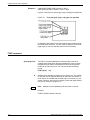
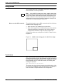
Negative coordinates
Negative coordinates also may be used. A negative y coordinate is
measured upward from the form origin. A negative x coordinate is
measured to the left of the form origin. For example, a vertical line
starting at x = -1 would appear to the left of the form grid as shown in
figure 3-7. When you use negative numbers, be sure to stay within
the boundaries of the system page.
XEROX DOCUPRINT 180 LPS FORMS CREATION GUIDE
3-15
FORMS DESCRIPTION LANGUAGE
Figure 3-7.
Use of a negative coordinate
LINE command
Specifying lines
The LINE command specifies that one or more lines are to be drawn
in the same direction. A LINE command defines the following:
•
•
•
•
•
•
Point at which the line begins (the AT location)
Direction of the line (HORIZONTAL or VERTICAL)
Length of the line (FROM location TO location)
Type of line (SOLID, BROKEN, DOTTED)
Thickness of the line (HAIRLINE, 0, 1, or 2)
Number of times the same line is to be drawn, either from
different origins or at specified intervals from the initial origin.
Use the following command format to specify lines:
co
3-16
Number representing the displacement from the form origin of the
first or only point of origin, expressed in grid units or linear units. The
remainder of the line command specifies the length and
characteristics of a line to be drawn at this location.
XEROX DOCUPRINT 180 LPS FORMS CREATION GUIDE
FORMS DESCRIPTION LANGUAGE
If a horizontal line is to be drawn, the co displacement is measured
on the y axis. If a vertical line is to be drawn, the c o displacement is
measured on the x axis. For example, if co is 6, a horizontal line is
drawn under the sixth character row.
n
unit
Number of lines to be drawn (Default is 1)
Unit of linear measurement, expressed as inches (IN), centimeters
(CM), DOTS, or XDOTS. If a linear unit is specified following IN, the
co parameter is assumed to be in the same units unless specified
after co. If units are not specified, the measurement is in grid units.
cs
Coordinate of the start of the line, measured on the x or y axis,
depending on the direction of the line.
ce
Coordinate of the end of the line, measured on the x or y axis,
depending on the direction of the line.
ca
Absolute x or y coordinate at which to start repetitive lines in a
horizontal or vertical direction. Multiple ca parameters can be
specified. Whether ca is measured on the y or x axis depends on the
horizontal or vertical direction of the line.
ci
An incremental number representing the grid units or linear units
between repeated lines.
Example:
AT 3 DRAW LINE FROM 4 TO 10;
XEROX DOCUPRINT 180 LPS FORMS CREATION GUIDE
3-17
FORMS DESCRIPTION LANGUAGE
Types of lines
The following types of lines may be drawn:
•
Solid
•
Broken Line is divided into many equal sections, separated by
small amounts of space
An unbroken, straight line
______________________________
•
Dotted
Line consists of dots of equal size and spaced equally
apart.
........................................
Lines may be of the following weights:
Hairline
1
2
0
LINE command defaults
(invisible)
The system defaults for direction and type of line are HORIZONTAL
and SOLID 1 and are adopted automatically if no other option is
specified. The default option of REPEAT is used to repeat a
horizontal line vertically and a vertical line horizontally to produce
parallel lines.
(The point of origin of a vertical line is at the top of the line at the
midpoint of the line thickness. A horizontal line point of origin is at the
left end of the line at the midpoint of the line thickness.)
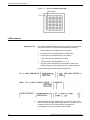
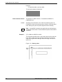
Example 1
AT 3 DRAW LINE FROM 4 TO 10;
AT 3
Keyword AT and the location down the page at
which the line is placed
DRAW
Keyword DRAW
LINE
Keyword LINE or LINES (When the number of
lines is omitted, one SOLID 1 line —the default
—is assumed).
FROM 4 TO 10
Keyword FROM and the coordinates indicating
the beginning and end of the lines
This command specifies the drawing of a horizontal line three grid
units down from the form origin, starting four grid units to the right of
the form origin and ending 10 grid units to the right of the form origin,
as shown in figure 3-8.
3-18
XEROX DOCUPRINT 180 LPS FORMS CREATION GUIDE
FORMS DESCRIPTION LANGUAGE
Figure 3-8.
Example 2
Drawing a horizontal line (rows and columns)
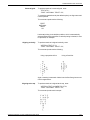
AT 3.5 DRAW LINE IN INCHES FROM 4 TO 10;
This command specifies the drawing of a horizontal line 3.5 inches
down from the form origin, beginning four inches to the right of the
form origin and ending 10 inches to the right of the form origin, as
shown in figure 3-9.
Figure 3-9.
XEROX DOCUPRINT 180 LPS FORMS CREATION GUIDE
Drawing a horizontal line (inches)
3-19
FORMS DESCRIPTION LANGUAGE
Example 3
AT 2 DRAW 5 VERTICAL LINES FROM 5 TO 10 AND REPEAT
EVERY 2;
This command specifies the drawing of five vertical lines. The first
line begins two horizontal grid units to the right of the form origin and
five grid units down from the form origin, and ends ten grid units down
from the form origin. This line is repeated every two horizontal grid
unit intervals, as shown in figure 3-10.
Figure 3-10. Drawing parallel vertical lines
Example 4
AT 4 DRAW 5 LINES FROM 2 TO 4 AND REPEAT HORIZONTALLY
EVERY 4;
This command specifies five short lines to be drawn, each two grid
units long, with each starting point spaced four grid units apart and
separated two grid units from the end of the preceding line, as shown
in figure 3-11.
Figure 3-11. Drawing repeated horizontal lines
3-20
XEROX DOCUPRINT 180 LPS FORMS CREATION GUIDE
FORMS DESCRIPTION LANGUAGE
BOX command
Specifying boxes
The BOX command is similar to the LINE command. It describes the
size and shape of a square or rectangular box. Like lines, boxes may
be repeated either at fixed intervals or at specified locations. The
origin of a box is its upper left corner at the midpoint of the outline
thickness. The format of the BOX command is as follows:
y
Coordinate on the y axis of the upper left corner of the box.
x
Coordinate on the x axis of the upper left corner of the box.
unit
Unit of linear measurement. Default is grid units.
n
Number of boxes to be drawn. Default is 1.
p
Width of the box.
q
Height of the box.
SOLID,BROKEN,DOTTED
Line style making up the border of the box.
HAIRLINE,0,1,2
Thickness of the border of the box.
SHADING
Filling the box with a gray shading.
LIGHT,MEDIUM,HEAVY
Relative intensity of the shading.
ca
Absolute x or y coordinate at which to start repetitive lines. Multiple
ca parameters can be specified.
ci
Incremental number representing the grid units or linear units
between repeated lines.
XEROX DOCUPRINT 180 LPS FORMS CREATION GUIDE
3-21
FORMS DESCRIPTION LANGUAGE
Example:
AT 4,6 BOX 24 BY 4 USI SHA HEA;
This example creates a shaded box:
BOX command defaults
0 lines
The default for LINES is SOLID 1. The default for REPEAT is
HORIZONTALLY.
Specifying a line thickness of 0 is useful for positioning text in an
invisible box. When using this technique, however, remember that 0
lines, although they are not printed, appear as lines internally.
Note: A single BOX command can specify either an outlined box or
a shaded box, but not both. That combination requires a second BOX
command.
Example 1
AT 4, 6 BOX 14 WIDE BY 4 HIGH;
This command specifies a box 14 grid units wide and four grid units
high, with the upper left corner four grid units down from the form
origin and six grid units to the right of the form origin, as shown in
figure 3-12.
Figure 3-12. Drawing a box
3-22
XEROX DOCUPRINT 180 LPS FORMS CREATION GUIDE
FORMS DESCRIPTION LANGUAGE
Example 2
AT .5,0 DRAW 4 BOXES IN INCHES 5 WIDE BY .5 HIGH USING
SHADING AND REPEAT VERTICALLY EVERY 2;
This command specifies four 5-inch wide, 0.5-inch high bars placed
with the top edges at 0.5 inches, 2.5 inches, 4.5 inches, and 6.5
inches as shown in figure 3-13.
Figure 3-13. Drawing boxes
Converting a 4850 color box
to a DocuPrint 180 black box
When the DocuPrint 180 prints a 4850 or 4890 form specifying a
color box, it converts the color box fill to a black box fill. In printing the
box, the DocuPrint 180 converts any shades of a color to a shade of
black or “grayscale.” Be aware, however, that solid-color boxes are
not converted to solid-black boxes. These solid-colors are also
printed in grayscale.
Using the SHIFT command with
SHADING on a DocuPrint 180
The SHIFT and XSHIFT parameter is a PDL feature that enables the
Programmer to adjust the data on a form to allow for three-hole
drilling or binding. Sometimes a negative SHIFT value can cause the
data to be shifted past the margin and off the page. This can easily
occur when shading is used near the leading edge of the paper.
Adjusting the SHIFT, ORIGIN and ALIGNMENT values can prevent
the shading image from shifting off the page at the leading edge. The
following example illustrates this point:
Example:
GRID [UNIT] [IS] 1 DOT, ORIGIN [IS] 0,0;
The system displays the following message:
Data origin off page. Check output
XEROX DOCUPRINT 180 LPS FORMS CREATION GUIDE
3-23
FORMS DESCRIPTION LANGUAGE
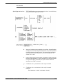
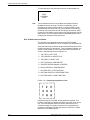
TEXT commands
Font requirement
At least one font must be specified before any text can be specified.
The FONT setup command is used, and only one such command
can be given for any one form. After the fonts are specified, they are
referenced in the form description, not by their identification name but
by an index number, beginning with 1 for the first font specified, 2 for
the second, and so forth.
The number of fonts that may be specified depends on their size, the
number of fonts used in the variable data, and the size of font
memory. Once a font number is specified in a TEXT command, it
remains in effect until a new font index is specified. If no font number
is specified in any TEXT command, the system uses FONT 1 as the
default substitute.
Two methods are available for specifying the text that is to be put on
forms. One places the text at a specified location anywhere on the
form. The other places text inside a box.
Using space options in text placement
FDL provides you with control over vertical line spacings and
horizontal character placement. The SPACED parameter in the
TEXT command is used to control the amount of vertical space
between two lines of text. Character spacing cannot be overridden.
However, each proportionally spaced font contains six space
characters of various widths to facilitate adjusting line length for text
applications.
Example:
TEXT SPACED 150 DOTS FONT 2;
TEXT AT
The following option allows you to print text in specific locations.
HORIZONTAL
VERTICAL
[ALIGNED]
TEXT
LEFT
RIGHT
CENTER
TOP
BOTTOM
[SPACED] d
DOTS
XDOTS
PTS
IN
CM
LPI
[PER LINE]
[[USING] FONT n]
AT y [unit] x [unit] ‘text‘ [‘text‘] . . . ;
d
3-24
Amount of vertical space occupied by a line of text. All specifications
except lpi are actual line height measurements. An lpi value specifies
line height in terms of lines per inch. The number must be positive
and may have two decimal places for all units except “DOTS.” The
default unit is “DOTS.”
XEROX DOCUPRINT 180 LPS FORMS CREATION GUIDE
FORMS DESCRIPTION LANGUAGE
n
Index number of the font to be used. If omitted, the system uses the
last font index specified in a TEXT command. If the font was omitted
in all previous TEXT commands, the system uses the first font
specified in the FONT command.
y
Coordinate on the y axis where the text origin is to be located.
x
Coordinate on the x axis where the text origin is to be located.
text
Text characters that are to be printed at the specified location.
Multiple text strings can be specified by enclosing each text string in
single quotation marks. Separate each text string with one or more
spaces. (A string is a series of characters.) Each string is printed as
one physical line of text. Text strings enclosed by single quotes (such
as ’abcde’) can be broken and continued onto the next input record;
the FDL compiler skips all embedded spaces until it finds the first
character of the next record.
Example:
TEXT AT 5, 1 ’FIRST’ ’NATIONAL’ ’TRUST’;
TEXT command defaults
Text line origins
If orientation and alignment are not specified, the defaults are
HORIZONTAL and CENTER.
The origin of a single line of text is the upper left corner of the first
character cell when the line appears upright to the viewer. The origin
of multiple lines of text is the upper edge of the topmost character cell
and leftmost edge of the leftmost character cell when viewed in an
upright position.
Some keywords in the command are explained below.
Keywords
Explanations
HORIZONTAL
VERTICAL
Specifies the direction in which text is to be printed relative to page
orientation (LANDSCAPE or PORTRAIT). HORIZONTAL is the
default.
TEXT
Command keyword
[SPACED]d
DOTS [PER LINE] Overrides the line spacing value of the font being used for this TEXT
XDOTS
command (if specified and not zero). POINTS and PTS have a unit
POINTS
value of 1/72 inch.
PTS
INCH[ES]
CM
CENTIMETER
LPI
[ALIGNED]
LEFT
RIGHT
CENTER
TOP
BOTTOM
Specifies how multiple strings of text are to be aligned. Multiple
horizontal strings may be centered underneath each other, or they
may be right-justified or left-justified. Multiple vertical strings may be
centered beside each other, or they may be aligned at the top or
bottom. The default is to center the strings.
XEROX DOCUPRINT 180 LPS FORMS CREATION GUIDE
3-25
FORMS DESCRIPTION LANGUAGE
Using toggles
Text originally entered at a 9700/8700 keyboard may contain number
signs (##). The number sign acted as a toggle to enable the user to
alternate between lower- and uppercase characters. Previously, this
was the only way to specify a change from uppercase to lowercase
and vice versa. The following is an example of the use of toggles to
change from uppercase to lowercase in a text string.
Entering:
‘R#ETAIL #D#ISTRIBUTION’
Produces:
‘Retail Distribution’
Although the current keyboards provide lowercase capability, it is
important to note that a form previously created on a 9700/8700
using toggles, will compile successfully on a 9790/8790, 4050, 4650,
4090, 4850/4890, 4135, 4635 or DocuPrint 180 LPS.
Aligning text
Text in forms may be left-aligned, right-aligned, or centered, as
illustrated in the examples that follow.
Left-aligned
To produce text that is left-aligned, enter:
TEXT ALIGNED LEFT AT 5,1
‘FIRST’ ‘NATIONAL’ ‘TRUST’ ‘CO’;
This command produces stacked, left-aligned output beginning five
grid units down from the form origin and one grid unit to the right of
the form origin, as follows:
FIRST
NATIONAL
TRUST
CO
Right-aligned
To produce text that is right-aligned, enter:
TEXT ALIGNED RIGHT AT 5,1
‘FIRST’ ‘NATIONAL’ ‘TRUST’ ‘CO’;
This command produces the following:
FIRST
NATIONAL
TRUST
CO
3-26
XEROX DOCUPRINT 180 LPS FORMS CREATION GUIDE
FORMS DESCRIPTION LANGUAGE
Center-aligned
To produce text that is center-aligned, enter:
TEXT AT 5,1
‘FIRST’ ‘NATIONAL‘ ‘TRUST’ ‘CO’;
To center the stacked words (the default option), an alignment need
not be specified.
This command produces the following:
FIRST
NATIONAL
TRUST
CO
Horizontal printing is the default condition, which is automatically
selected without being specified. If vertical printing is desired, it must
be specified, for example:
Aligning vertically
To produce text that is aligned vertically, enter:
VERTICAL TEXT AT 5,1
‘FIRST’ ‘NATIONAL’ ‘TRUST’ ‘CO’;
This command produces the following:
Using a proportional font
Using a fixed font
Again, centering is automatic. Notice how the fixed font gives a more
uniform appearance.
Aligning at the top
To produce text that is aligned at the top, enter:
VERTICAL TEXT ALIGNED TOP AT 5,1
‘FIRST’ ‘NATIONAL’ ‘TRUST’ ‘CO’;
This command produces this output:
XEROX DOCUPRINT 180 LPS FORMS CREATION GUIDE
3-27
FORMS DESCRIPTION LANGUAGE
Aligning at the bottom
To produce text that is aligned at the bottom, enter:
VERTICAL TEXT ALIGNED BOTTOM AT 5,1
‘FIRST’ ‘NATIONAL’ ‘TRUST’ ‘CO’;
This command results in the following:
Other character-block orientations are shown in figures 3-14 and
3-15 on the following two pages.
3-28
XEROX DOCUPRINT 180 LPS FORMS CREATION GUIDE
FORMS DESCRIPTION LANGUAGE
Figure 3-14. Character block orientations for a portrait page
denotes the positioning origin of the text block.
If the font and page have the same orientation, letters appear upright. They appear sideways or upside down
if orientations differ. Text is aligned horizontally or vertically relative to page orientation, not relative to the
font.
Portrait and inverse portrait fonts may be used with landscape page orientation, for example, to insert labels
or captions. Likewise, landscape and inverse landscape fonts may be used with portrait page orientation.
Portrait, landscape, inverse portrait, and inverse landscape fonts are listed in the Xerox Laser Printing
Systems Standard Font Library Font User Guide and Xerox 4850 Highlight Color and 4135 Laser Printing
Systems Font User Guide.
XEROX DOCUPRINT 180 LPS FORMS CREATION GUIDE
3-29
FORMS DESCRIPTION LANGUAGE
Figure 3-15. Character block orientations for a landscape page
denotes the positioning origin of the text block.
3-30
XEROX DOCUPRINT 180 LPS FORMS CREATION GUIDE
FORMS DESCRIPTION LANGUAGE
TEXT IN BOX
Specifying text in a box
TEXT IN BOX allows you to place text within a box. Use the following
command format to place text in a box:
d
Amount of vertical space occupied by a line of text. All specifications
except lpi are actual line height measurements. An lpi value specifies
line height in terms of lines per inch. The number must be positive
and may have two decimal places for all units except dots. The
default unit is “dots.”
n
Index number of the font to be used. If omitted, the system uses the
last font index specified in a TEXT command. If the font was omitted
in all previous TEXT commands, the system uses the first font
specified in the FONT command.
y
Coordinate on the y axis where the box origin is located.
x
Coordinate on the x axis where the box origin is located.
Example:
TEXT IN BOX 4 3 ‘FIRST’ ‘NATIONAL’ ‘TRUST’;
XEROX DOCUPRINT 180 LPS FORMS CREATION GUIDE
3-31
FORMS DESCRIPTION LANGUAGE
This example prints the following text within the designated box:
FIRST
NATIONAL
TRUST
text
Text characters that are to be printed at the specified location.
Multiple text strings (a string is a series of characters) can be
specified by enclosing each text string in single quotation marks.
Separate each text string with one or more spaces. Each string is
printed as one physical line of text.Text strings enclosed by single
quotes (such as ’abcde’) can be broken and continued onto the next
input record. The FDL compiler skips all embedded spaces until it
finds the first character of the next record.
TEXT IN BOX command defaults
The defaults for the optional keywords in the TEXT IN BOX
command are HORIZONTAL, DOTS, CENTER, and HORIZONTAL.
A box with matching coordinate values must be defined before TEXT
IN BOX command can reference it. Thus the statement allows nine
options for the position in a box where the text is to be placed, as
shown in the following list and in figure 3-16.
1. TOP LEFT or LEFT TOP
2. TOP CENTER or CENTER TOP
3. TOP RIGHT or RIGHT TOP
4. LEFT CENTER or CENTER LEFT
5. CENTER CENTER (default) or CENTER
6. RIGHT CENTER or CENTER RIGHT
7. BOTTOM LEFT or LEFT BOTTOM
8. BOTTOM CENTER or CENTER BOTTOM
9. BOTTOM RIGHT or RIGHT BOTTOM.
Figure 3-16. Possible text positions in box
Note that except for CENTER, two keywords are required. If no
location is specified, the default is to place text in the center of the
box. If the font selected causes the text to overflow the box or
overflow the page, the system prints the form as specified and
generates a message indicating the maximum size font, in points,
that will fit in the allotted space.
3-32
XEROX DOCUPRINT 180 LPS FORMS CREATION GUIDE
FORMS DESCRIPTION LANGUAGE
The following examples demonstrate these nine positions.
TOP LEFT
TEXT ALIGNED LEFT FONT 1 IN TOP LEFT BOX 10,20 ’PART
NUMBER’;
PART NUMBER
TOP CENTER
TEXT ALIGNED CENTER FONT 2 IN TOP CENTER BOX 10,10
’PART NUMBER’;
PART NUMBER
TOP RIGHT
TEXT ALIGNED RIGHT FONT 3 IN TOP RIGHT BOX 5,5 ’PART
NUMBER’;
PART NUMBER
LEFT CENTER
TEXT ALIGNED LEFT FONT 3 IN LEFT CENTER BOX 35,5 ’PART
NUMBER’;
PART NUMBER
CENTER CENTER
TEXT FONT 1 IN CENTER CENTER BOX 12,5 ’PART NUMBER’;
PART NUMBER
RIGHT CENTER
TEXT ALIGNED RIGHT FONT 1 IN RIGHT CENTER BOX 32,3
’PART NUMBER’;
PART NUMBER
XEROX DOCUPRINT 180 LPS FORMS CREATION GUIDE
3-33
FORMS DESCRIPTION LANGUAGE
BOTTOM LEFT
TEXT ALIGNED LEFT FONT 1 IN BOTTOM LEFT BOX 20,10 ’PART
NUMBER’;
PART NUMBER
BOTTOM CENTER
TEXT ALIGNED CENTER FONT 3 IN BOTTOM CENTER BOX
40,10 ’PART NUMBER’;
PART NUMBER
BOTTOM RIGHT
TEXT ALIGNED RIGHT FONT 1 IN BOTTOM RIGHT BOX 10,40
’PART NUMBER’;
PART NUMBER
Adjacent boxes
The BOX position is specified by the coordinates of the upper left
corner of the box in which the text string is to be placed. If text is to
be placed in an adjacent box (either vertically or horizontally
adjacent), this can be specified by an IN NEXT BOX parameter,
having the following form:
[[IN] [NEXT] HORIZONTAL | VERTICAL BOX ‘text‘ [‘text‘ . . . ]] . . . ] ;
To be considered adjacent, the boxes must have a common side.
The keywords IN NEXT HORIZONTAL BOX specify the next
horizontal box to the right of the current box. The keywords IN NEXT
VERTICAL BOX specify the box beneath the current box. These
adjacent boxes are shown in figure 3-17. The default is
HORIZONTAL.
Figure 3-17. Adjacent boxes
3-34
XEROX DOCUPRINT 180 LPS FORMS CREATION GUIDE
FORMS DESCRIPTION LANGUAGE
Assuming that the upper left corner of the first box above is located
two grid units down from the form origin and one grid unit to the right
of the form origin, you would use the following statements:
TEXT IN BOX 2,1’A’
or
TEXT IN BOX 2,1’A’
IN NEXT BOX ’B’
BOX ’B’
IN NEXT BOX ’C’
BOX ’C’
IN NEXT VERTICAL BOX ’D’
VERTICAL BOX ’D’
The results of either statement are shown in figure 3-18.
Figure 3-18. Placing text in adjacent boxes
XEROX DOCUPRINT 180 LPS FORMS CREATION GUIDE
3-35
FORMS DESCRIPTION LANGUAGE
LOGO command
Placing logos
A complex figure called a logo, up to two square inches in size, can
be digitized to order by the Xerox Font Center or Xerox Limited. This
logo is a special font of one or more characters, which carries with it
the relative position of the characters to make up the logo. Thus,
while a logo may be made up of many characters, it is positioned as
a single unit. For additional flexibility, a signature may be digitized
and stored on the system as a logo.
Note: Be sure that font memory capacity is not exceeded. Logos
larger than two square inches may be used if they are the result of
using smaller components of the logo to gain the desired effect.
Placement is accomplished with the following command:
LOGO id AT y [unit] x [unit];
The logo identifier (1 to 6 characters) is id.
Example:
LOGO EAGLE AT 10, 12;
LOGO ORIGIN: - - - >
LOGO
Keyword LOGO
EAGLE
The name of the logo, which is a one to six
alphanumeric character label, is assigned to the logo
when it is digitized by the Xerox Font Center or Xerox
Limited.
AT 10, 12 The keyword AT and the coordinates (y,x) indicate
where the top left corner of the logo is to be placed.
Sample FSL
The LOGO command is typically inserted towards the end of the FSL
as illustrated in figure 3-19.
Figure 3-19. Placing a logo
HORIZONTAL TEXT USING FONT 2 IN CENTER CENTER
BOX 6,1 ’DATE’;
COMMENT *** PLACE LOGO ***;
LOGO RABBIT AT 1,26;
END;
3-36
XEROX DOCUPRINT 180 LPS FORMS CREATION GUIDE
FORMS DESCRIPTION LANGUAGE
GRAPHIC command
Using graphics
A form may consist solely of graphics (images). Up to 16 images per
page are permitted. Interpress and graphics capability (Advanced
Imaging Subsystem—AIS), enable the printing of more than 16
images per page as well as vector graphics. Refer to your DocuPrint
180 LPS Operations Reference for additional information on AIS.
Each graphic to be associated with a form must be specified in the
FSL file by a statement with the following syntax:
GRAPHIC name AT vpos [unit] ,hpos [unit] [SCALE [IS] n[/
d]];
Sample FSL
Similar to the LOGO command, the GRAPHIC command is also
typically placed near the end of the FSL, as shown in figure 3-19.
name
Name of graphic (IMG) file, found on the system disks.
vpos
Specifies the vertical position of the top edge of the
graphic relative to the virtual page origin. This
parameter is a decimal number with up to two
fractional digits (except for dots, which must be an
integer). If no unit is specified, grid unit dimensions are
used as the default.
unit
Unit of linear measurement, expressed as inches (IN),
centimeters (CM), or DOTS. If units are not specified,
grid unit dimensions are used.
hpos
Specifies the horizontal position of the left edge of the
graphic relative to the virtual page origin. The form of
the specification is the same as for vpos.
n/d
Specifies the reference scale factor. Each parameter,
n and d, must be an integer in the range of 1 to 8,
thereby allowing a reference scale factor in the range
of 1/8 to 8. The reference scale factor is multiplied by
that specified at the time the graphic was digitized,
and the product is rounded to the nearest integer in
the range 1 to 8. That integer becomes the effective
scale factor with which the graphic is imaged.
Example:
GRAPHIC AFJ AT 10, 12;
Figure 3-20. Placing a graphic
AT 31.6,31.6 DRAW
USING SOLID 2;
AT 31.9,31.9 DRAW
USING SOLID 2;
AT 32.2,32.2 DRAW
USING SOLID 2;
GRAPHIC UNICRN AT
TEXT USING FONT 1
XEROX DOCUPRINT 180 LPS FORMS CREATION GUIDE
BOX 46.8 WIDE BY 21.8 HIGH
BOX 46.2 WIDE BY 21.2 HIGH
BOX 45.6 WIDE BY 20.6 HIGH
31.5,42;
AT 83.5,2.5 ’FORM SM105’;
3-37
FORMS DESCRIPTION LANGUAGE
SECTION commands
Defining a section
When a form consists of several identical sections, you can save time
by defining only one section and treating it as a module, that is,
having it repeated at desired locations. This is done with the following
command:
[BEGIN] SECTION id;
The id is an identifier (1 to 6 characters) that is invoked when a
section is to be defined.
The command can also be used to define an entire form as a section.
Within the section, any other command, statement, or specification
may be used except another SECTION command, DO SECTION
command, FORM command, or END command. More than one
section may be defined and invoked, but each section must be
terminated with the following command before another section can
be defined:
END SECTION;
Invoking a section
To invoke a section that has been defined, the section identifier is
invoked with the following command:
DO SECTION id AT y [unit] x [unit];
A section must be defined before it can be invoked.
Sample FSL
Figure 3-21 illustrates how the SECTION commands are invoked.
Figure 3-21. Specifying a section
FORM SEC 4;
PORTRAIT;
GRID FMT8;
FONT UN207B;
COMMENT *** CREATE PHONE MESSAGE PAD SECTION ***;
BEGIN SECTION PHONE;
AT 7 DRAW 7 HORIZONTAL LINES FROM 4 TO 33 USING SOLID 1 AND REPEAT
VERTICALLY AT 11,17,20,23,26,29;
HORIZONTAL TEXT USING FONT 1 AT 2,4 ’PHONE MESSAGES’;
HORIZONTAL TEXT USING FONT 1 AT 4,4 ’CALLER:’;
HORIZONTAL TEXT USING FONT 1 AT 8,4 ’TIME:’;
HORIZONTAL TEXT USING FONT 1 AT 12,4 ’MESSAGE:’;
END SECTION;
COMMENT *** PRINT MESSAGE PAD SECTION 4 TIMES ***;
DO SECTION PHONE AT 0,0;
DO SECTION PHONE AT 30,0;
DO SECTION PHONE AT 0,37;
DO SECTION PHONE AT 30,37
END;
3-38
XEROX DOCUPRINT 180 LPS FORMS CREATION GUIDE
FORMS DESCRIPTION LANGUAGE
SECTION command syntax
BEGIN SECTION PHONE;
BEGIN SECTION
Keywords
PHONE;
Name of section. Rules for naming sections
are identical to those for naming forms: one to
six alphanumeric characters.
END SECTION;
END SECTION;
Finishing command. Notice that the END
SECTION command does not use the section
name. Including a section name results in an
error.
DO SECTION PHONE AT 0,0;
DO SECTION PHONE AT 30,37;
DO SECTION
Keywords
PHONE
Section name. The section must have been
previously defined by BEGIN SECTION and
END SECTION commands.
AT 0,0;
AT 30,37;
XEROX DOCUPRINT 180 LPS FORMS CREATION GUIDE
Coordinates of the origin of the section in
relation to the origin of the form.
3-39
FORMS DESCRIPTION LANGUAGE
COMMENT command
Recording comments
It is frequently helpful to include comments in the source statements
to describe certain FDL commands and their functions. These
comments are useful when debugging your program, and can act as
reminders if you, or someone else, modifies the FSL at a later time.
When you use comments, they appear on the source statement only.
They are not printed on your form nor do they affect the execution of
your program.
Enter the word COMMENT, then the text that describes the
command or procedure, followed by a semicolon.
Important: The semicolon must be inserted at the end of the
comment text, otherwise all of the following FDL commands are
considered part of the comment text and are not executed. All
comments up to the first semicolon encountered are ignored by the
FDL compiler.
The format of the comment command is:
COMMENT text;
Asterisks and or line spacing cause the COMMENT to stand out from
the text.
Example:
COMMENT *** DRAW HORIZONTAL LINES ***;
Sample FSL
This sample illustrates a COMMENT that identifies the procedure
that is to follow:
COMMENT *** PLACE SECTIONS ***;
DO SECTION RSPNSE AT 0,0;
DO SECTION RSPNSE AT 7,0;
DO SECTION RSPNSE AT 14,0;
Comment nesting
/* begins a comment and */ ends a comment.
Example:
/* THIS IS THE START OF A NESTED COMMENT
/* WHEN TWO ENDING COMBINATIONS ARE FOUND */
THE COMMENT IS TERMINATED */
A syntax error results if /* does not begin a comment, and */ does not
end a comment. Each comment beginning (/*) and ending (*/) should
be followed by at least one space character.
3-40
XEROX DOCUPRINT 180 LPS FORMS CREATION GUIDE
FORMS DESCRIPTION LANGUAGE
END command
Terminating an FSL
The description of a form is terminated with an END command. The
command syntax is as follows:
END;
An FSL file can contain more than one file. Therefore, if additional
FSL files follow an END command, the end of all FSLs to be
processed is indicated by two consecutive END commands. The
command syntax is:
END;END;
XEROX DOCUPRINT 180 LPS FORMS CREATION GUIDE
3-41
FORMS DESCRIPTION LANGUAGE
3-42
XEROX DOCUPRINT 180 LPS FORMS CREATION GUIDE
4.
4Compiling and printing forms
Once the file of forms source library (FSL) commands has been
created, the file can be stored on the DocuPrint 180 LPS system disk.
The next step is to compile the file and print a copy of the form.
Form printing processing
To print an electronic form on your laser printing system:
Enter the editor utility and create a file of FDL commands to describe
the form. This file is called a forms source library (FSL) file. (Refer to
chapter 3, "Forms description language," of this guide.)
Creating an FSL form
You create an FSL file containing FDL commands such as
coordinates for placing lines, boxes, text, and so forth. You can
create the FSL file directly at the LPS PC User Interface, at a host
computer input device, or through remote communications.
XEROX DOCUPRINT 180 LPS FORMS CREATION GUIDE
4-1
COMPILING AND PRINTING FORMS
Communicate the FSL file to the LPS system disk
Once you have created the FSL file, you can send it to the system
disk either offline or online.
Offline
In the offline mode, FSL files can be transmitted to the system disk
from magnetic tape or by using the LPS Editor.
Using magnetic tape
Step 1.
Create the source file at the host computer and store it on a magnetic
tape.
Step 2.
Mount the tape on the LPS tape drive and transmit the files
electronically to the system disk.
The source code can be entered directly to the LPS at the PC User
Interface keyboard and transmitted electronically to the system disk.
Online
Remote communications
If your LPS is channel-attached to a host computer, enter the source
code at the host terminal through the host editor facility. The file must
be preceded by the necessary control record identifiers. Refer to your
host reference documentation for details. The LPS Hostcopy utility
enables you to download files from the host to be stored on the LPS
system disk. Your DocuPrint 180 LPS Operations Reference
explains the Hostcopy commands in detail.
The LPS can also receive forms data from a remote device on the
Ethernet network.
Compiling a form
Once the file has been created, the next step is to enter the command
that causes the source file (FSL) to be compiled into an object file
(FRM).
Invoking the forms compiler
To invoke the forms compiler, enter the following command at the
LPS keyboard:
FDL [parameters]
The FDL compilation command includes any combination of the
following options.
Note:
The entire command must fit on one line.
FDL [filename][,NOPRINT][,TRAY][,DEBUG][,XPAN][,NOSOURCE][,PROOF][,SIMPLEX]RES={300 | 600}]
FDL[filename][,NOPRINT][,TRAY][,DEBUG][,XPAN][,NOSOURCE][,PROOF][,SIMPLEX]RES={300 | 600}][,TDn]
4-2
XEROX DOCUPRINT 180 LPS FORMS CREATION GUIDE
COMPILING AND PRINTING FORMS
filename
Specifies the name of an FDL source file in the FSL directory on the
system disk that is to be used for source input to the FDL compiler.
The file extension, .FSL, may be included; no other extension is
allowed. The file name may not be a keyword option such as TRAY,
DEBUG, XPAN, and so on. These are reserved names that could
cause problems when you use a task outside the forms compiler.
NOPRINT
Specifies that no listing of the FDL source statements, no form
summary, and no sample form are to be printed. However, if an error
occurs during the processing of the form, the listing and the summary
are printed.
TRAY
DEBUG
XPAN
NOSOURCE
PROOF
SIMPLEX
RES=300
or
RES=600
TDn
Specifies that the sample form, source statement, and summary
sheet are to go to the sample tray instead of the currently active
output stacker.
Specifies that no attempt to print the sample form is to be made. This
ensures that the source statement and summary sheet are printed
even if the sample form cannot be printed.
Specifies printing of the source statement of section expansion.
Specifies that disk source file creation will be suppressed when
compiling from magnetic tape or disk, when the form name is the
same as the file name given.
Specifies that the FSL is to be compiled and the source statement
and or summary sheet is to be printed. No FRM file is generated.
Specifies that the source statement and or summary sheet generated
with each compile is printed in simplex rather than duplex.
Specifies the resolution at which the form should be compiled.
The tape drive containing the FSL if you are compiling from tape. All
DocuPrint 180 tape devices can be referenced using TD0, TD1, and
TD2. Refer to your DocuPrint 180 LPS Operations Referenc e for
detailed information.
Note: If the source file contains multiple form descriptions, the
system does not start printing until all forms have been compiled.
Compiling 600 spi forms
A 600 spots per inch (spi) form can be compiled on a DocuPrint 180
printer even though it may be unable to print the form. It is important,
however, that all 600 spi system fonts, logos, and image files are
loaded on that system prior to compilation.
XEROX DOCUPRINT 180 LPS FORMS CREATION GUIDE
4-3
COMPILING AND PRINTING FORMS
Compiling 4850/4890 color forms and
logos
Color forms created on a 4850 or 4890 LPS cannot be compiled on
the DocuPrint 180 LPS. However, a form or logo that was created
and compiled on a 4850/4890 can be printed (in monochrome black)
on your DocuPrint 180 LPS.
There are no restrictions with a color form referencing a monochrome
image file or with a monochrome color form referencing a color image
file.
Summary sheet
If the compilation is successful, a summary sheet of statistics is
printed, containing the following:
•
•
•
•
Simplex and duplex
Size of the source output file
Size of the printable form file
Size of the form image buffer
Total amount of font memory used.
This sheet is by default printed duplex. If you want it printed simplex,
include the SIMPLEX option in the task invocation line as follows:
FDL TRYIT,SIMPLEX
Pagination
Multiple FSLs contained in one file are paginated so that each new
FSL starts on the front side of a new page.
Error checking
If the compilation fails, a list of error messages is printed.
As the FSL file is processed, it is automatically checked to see that
the following errors have not occurred:
•
•
•
•
Unknown commands, keywords, or parameters
•
•
•
Invalid font or logo requests
Illegal or conflicting commands, keywords, or parameters
Missing commands, keywords, or parameters
Requests for items to be placed or drawn outside of box or
page boundaries
Illegal grid units
Illegal syntax.
Errors are flagged in the source statement with messages specifying
the type of error. Refer to appendix B, “FDL-generated messages” for
a description of error messages that may appear while forms are
being compiled.
4-4
XEROX DOCUPRINT 180 LPS FORMS CREATION GUIDE
COMPILING AND PRINTING FORMS
PROOF option
The forms compiler makes it possible to compile a form and delete
the FRM file after it has been printed. If you use this option, less disk
space is consumed by resident form files. To invoke the PROOF
option, enter the following:
FDL TRYIT,PROOF
If the form is compiled with no errors, the FRM file and the source
statement and or summary sheet is printed. Since the PROOF option
causes it to be deleted, no form file then resides on the disk.
Note: When you use the PROOF option, the form file that is
created is given a pseudo-name that differs from the one specified in
the FSL. Therefore, when TRYIT.FSL, for example, is compiled, the
form that is created is not automatically named TRYIT.FRM. The
newly created .FRM file is given a different name, and it is this
renamed form that is eventually deleted. Due to this safeguard, if a
file named TRYIT.FRM already exists on the system disk, that form
still exists after the new FRM file is compiled and deleted.
Secured files
Caution: If you attempt to overwrite a secured file while compiling
a form, a security violation message appears and the compilation
process is aborted.
•
If you attempt to overwrite a secured file having the same name
both on the task invocation line and in the .FSL itself, a security
violation message is displayed and the form is aborted.
Example:
TRYIT1.FSL is a secured file:
You enter:
FDL TRYIT1,TRAY
FSL contains:
FORM TRYIT1;
GRID IS 1 INCH;
END;END;
In this case, a security violation message would appear and
compilation would abort.
XEROX DOCUPRINT 180 LPS FORMS CREATION GUIDE
4-5
COMPILING AND PRINTING FORMS
•
If the form names on the invocation line and in the FSL are
different, the compilation is aborted and a single sheet is
printed. It contains the heading for the page and the portion of
the FSL that was processed before the security violation was
detected.
Example:
TRYIT1.FSL is a secured file:
You enter:
FDL TRYIT,TRAY
FSL contains:
FORM TRYIT1;
GRID IS 1 INCH;
END;END;
In this case, a security violation message would still appear and the
compilation would abort, but a single page would be printed
containing the page heading and the FSL line “FORM TRYIT1;”
Example 1
FDL TRYIT,TRAY
This command causes the system to compile the FSL named
“TRYIT” (provided it does not contain errors), generate the source
statement, print a copy of the statement and the form, and deliver
both to the SAMPLE tray.
If you do not include the word TRAY in your command, the printout is
delivered to the currently active bin.
Example 2
If you want to compile the form but you do not want a printout of the
form just yet, enter the following:
FDL TRYIT,NOPRINT
The FSL compiles, but the form and the source statement does not
print.
Debugging and modifying the file
Whenever you first create a file, it rarely produces the form exactly as
you imagined it to look.
•
You may have syntax errors which prevent the form from
printing.
•
You may have successfully followed all the FDL rules and
produced a form, but you inadvertently placed some text or
graphic on the form in the wrong place or misspelled a word.
•
Everything comes out the way you planned it, but the printed
form just doesn’t look right (that is, it would look better if that
box were a little larger).
It is easy to identify the specific cause of the problem (debugging)
and correct it (modifying). Your DocuPrint 180 Operations Reference
provides a complete explanation on how to modify your FSL file.
4-6
XEROX DOCUPRINT 180 LPS FORMS CREATION GUIDE
COMPILING AND PRINTING FORMS
Storing form files
A large number of forms may be stored in the forms source directory
(uncompiled) and form directory (compiled) on the system disks. Two
files with the same name may not, however, be stored in the same
directory. The number of forms that can be stored depends on the
amount of data required to describe each form and the total amount
of disk space allocated to the libraries.
The forms are filed in the system under their identifying names.
Information stored in the file includes the identifier, the encoded form,
and the list of fonts and logos specified. The original source
statements that created the forms description are stored separately
under the same identifier.
A list of all forms stored in the directory, a sample of each, and the
source statement lists can all be obtained by operator commands.
(Refer to your DocuPrint 180 LPS Operator Guide .)
Printing a compiled form
Once a form has been compiled, the object code is stored on the
system as a FRM file. To print copies of the form, enter the SAMPLE
command at the LPS PC User Interface. The format of the SAMPLE
command is:
SAM[PLE] filename.FRM
Example
SAM[PLE]TRYIT.FRM
To produce five copies of the form, enter the following:
SAM[PLE]TRYIT.FRM,5
When an FRM is compiled, the paper size is defined by the PAPER
SIZE IS XX BY YY statement in the FSL. If the paper size is not
defined, the paper size defaults to the sysgened paper size.
XEROX DOCUPRINT 180 LPS FORMS CREATION GUIDE
4-7
COMPILING AND PRINTING FORMS
FDL compilation time
The time it takes to compile a form file depends on the position of the
font file in its directory and the size and number of disks on the
system. If your LPS has a large number of font files that are
dispersed over several disks, you may notice an increase in
compilation time for forms that perform text handling. To ensure that
your form files compile as quickly as possible, remove unnecessary
font files and use the COMPRESS utility to reorganize your files on
the disk. Your DocuPrint 180 LPS Operations Reference explains
how to compress files and delete files that are no longer needed.
These recommendations will shorten the font lookup time and make
the most efficient use of the disk space.
4-8
XEROX DOCUPRINT 180 LPS FORMS CREATION GUIDE
5.
5Forms layout considerations
Physical printer constraints and forms compiler methods are factors
that can affect form design. This chapter explores the implications of
these factors relative to the following:
•
•
•
•
•
•
Image complexity
Boxes
Shading
Sections
Rounding measurements
Coding techniques
Image complexity
Form design is limited by physical restrictions on the amount of
image data (characters and lines) that can be printed on a scan line
and on a page.
Line tables
Forms Description Language (FDL) line tables are internal FDL data
structures providing a record in memory of the lines to be drawn on
a page. These tables allow the system to find the corners and edges
of boxes when they are referenced at a later time.
Since excessive amounts of memory would be required to store
every line, the FDL compiler retains only the memory of the longest
lines that pass through any given coordinate in a particular direction.
For dotted or broken lines, FDL replaces them with an invisible line
of the same length.
Line table limits
The FDL line tables can store 2,000 vertical and 2,000 horizontal
lines in memory. Whenever the line tables become too full and
exceed either of these limits, a warning-level error message is
displayed:
TOO MANY HORIZONTAL LINES or TOO MANY VERTICAL LINES
This message warns you that the new user-specified line cannot be
retained in the table. The error message is of no real consequence to
you unless the new line is intended as the side of a box. In that case,
the box is not found, and a serious error message results.
XEROX DOCUPRINT 180 LPS FORMS CREATION GUIDE
5-1
FORMS LAYOUT CONSIDERATIONS
Generally, the line table limits are reached because the form contains
a large number of short line segments. The most probable reason for
this is a series of vertical lines that are aligned vertically (for example,
tick marks) or horizontal lines that are aligned horizontally (for
example, a series of long dashes). With either of these conditions, it
is possible to reduce the number of entries in the line table as the
form is being constructed.
Importance of orderly construction
One consideration in determining the orderliness of form construction
is that the algorithm used in loading the line table is designed to
check only two criteria before entering a new line in the line table:
•
Is the new line contained within the boundaries of an existing
line?
•
Is the new line an extension of one of the existing lines?
If the new line is contained within the boundaries of an existing line,
no change is made to the line table entries. If the new line is an
extension of one of the existing lines, the boundaries of the first (and
only the first) existing line are extended to include the new line. If
neither of the criteria is met, a new entry is made in the line table.
Examples
The procedure of line extension results in an interesting irregularity if
lines are not specified in an orderly manner. For example, draw five
line segments that are each five units in length. If the lines are drawn
in an unreasonable or irregular manner, as shown below, the result
is more entries in the line table than are necessary. Drawing line
segments in the order 0 to 5, 10 to 15, 20 to 25, 5 to 10, and 15 to 20
creates a single visual line that FDL considers to be three lines. This
is because the criterion of the line table allows extension of only the
first line segment with common coordinates to the new line. In the
case described, the three line entries in the line table would be 0 to
10, 10 to 20, and 20 to 25. Figure 5-1 shows examples of extraneous
lines drawn.
Figure 5-1.
5-2
Example of extraneous lines drawn
XEROX DOCUPRINT 180 LPS FORMS CREATION GUIDE
FORMS LAYOUT CONSIDERATIONS
In addition, it is possible to have the line table show more than one
line passing in the same direction through a given coordinate. For
example, draw three lines, each of which is five units in length (0 to
5, 10 to 15, and 20 to 25). Then draw two lines, each of which is nine
units in length (3 to 12 and 13 to 22). The result is a single visual line
for which FDL has three entries in the line table (0 to 12, 10 to 22, and
20 to 25). Figure 5-2 shows lines entered in unintended locations.
Figure 5-2.
Lines entered in unintended locations
These two examples of awkwardly entering lines into the line table
result in lines that are visually contiguous but not logically
contiguous. As indicated in the subsequent sections that describe
problems with boxes, such conditions can result in a situation where
FDL is unable to find a box or creates a box that has one or both of
its dimensions equal to zero.
Suggested techniques for
entering lines
The suggested technique for entering lines is to draw the longest
possible logical line first, then draw any shorter elements. If the
logical line consists of different types of lines (for example, solid and
dotted), draw a SOLID 0 line first extending over the full range of the
logical line. For instance, the previously cited example of five line
segments of five units each might have consisted of alternating solid
and dotted lines. In that case, the most reasonable method of
specifying the total line would be as follows:
AT 0 LINE 0 TO 25 USING SOLID 0;
AT 0 LINE 0 TO 5 USING SOLID 2 AND AT 10, 20;
AT 0 LINE 5 TO 10 USING DOTTED 1 AND AT 15;
Figure 5-3 shows the line that would be drawn.
Figure 5-3.
XEROX DOCUPRINT 180 LPS FORMS CREATION GUIDE
Line made up of different types of lines
5-3
FORMS LAYOUT CONSIDERATIONS
Scan line density
“Scan line” density is dependent upon printer speed and imaging
speed. Therefore, it can vary with each product and even with
different configurations of the same product. The basic limitation is
linked to dispatchable items, which become visible in character count
and number of lines.
Line density errors
Both characters and lines contribute to the dispatchable item count.
When one dispatchable item is superimposed over another
dispatchable item, the result is considered to be two dispatchable
items by the system. When too many dispatchable items are present
on a scan line on the long axis of the paper, the LPS operating
system displays a line density error message:
OS6950 LINE DENSITY EXCEEDED
There is a hardware limitation of 320 dispatchable items per 300-spi
scan line (640 for 600 spi), which includes the required overhead of
two dispatchable items. For example, a dispatchable item could be a
maximum of 32 dots wide for 300 spi (64 dots for 600 spi) and thus
might be a full character (less than point size 8 or 9), a fraction of a
character (greater than point size 8 or 9), or a line segment that is
equal to or smaller than 32 dots in the scan direction.
Determining line density limitations
The following is a guide for determining 300-spi line density
limitations. If printing at 600 spi, the same size character or same
length line will have twice as many dots.
•
Each 32 dots (or fraction thereof) of a line drawn on the long
axis of the paper is one dispatchable item.
•
Each line drawn on the short axis of the paper is one
dispatchable item.
•
Each active character is at least one dispatchable item. (An
active character includes all the space from the top of the
character cell to the bottom of the character cell, even if there is
only white space present on a given scan line.) If the dimension
along the scan line is greater than 32 dots, the character
consists of some multiple dispatchable items.
It is not possible to construct a form with two adjacent lines if both use
the full count of 318 (320 minus the two required for overhead)
dispatchable items resulting from text and lines. The imaging system
requires a rest period of about four scan lines before it can image the
second fully loaded line.
As discussed below, line density restrictions differ as a function of the
mode (landscape or portrait) of the form.
5-4
XEROX DOCUPRINT 180 LPS FORMS CREATION GUIDE
FORMS LAYOUT CONSIDERATIONS
Landscape pages
Line density restrictions differ as a function of the mode (landscape
or portrait) of the form. An 8-point or smaller landscape font is smaller
than 32 dots for 300 spi and 64 dots for 600 spi. A vertical line is a
single dispatchable item. A horizontal line is treated as a series of
lines that are 32 dots in length joined end-to-end.
For 300 spi, this means that a form using an 8-point or smaller font
on a landscape page may have up to 318 characters (plus a two-item
overhead, resulting in 320 dispatchable items) on a scan line. When
using a 6-point font, it is possible to have, for example, 132
characters, a line across the page under the text, as well as 80 to 90
vertical lines, without exceeding the line density limitations.
If a form requires a 9-point or larger font, the number of characters
that may be imaged on a landscape page is reduced to 160 because
the characters are generally more than 32 dots wide. While the
dispatchable-item count remains 320 per line, fonts 9 points and
larger use two dispatchable items per character. Since a character in
a large font constitutes two dispatchable items, only half as many
characters in a large font may be imaged on a scan line as is possible
with a smaller font.
Portrait pages
Restrictions for a portrait page are significantly different from those
for a landscape page because the system always images in a
landscape direction. Therefore, if a page is formatted as a portrait
page, the hardware must take the time to reorganize the data into
landscape prior to imaging.
Thus, for a 300-spi portrait page, this drops the dispatchable-item
count below the 320-character level when a 12-point font is used.
That is, with a 12-point font, a form may have not more than 160
characters on a scan line.
When using an 8-point 300-spi font on a portrait page, the maximum
dispatchable-item count permitted is approximately 200 per scan
line. This limit falls off gradually to 170 characters for a 6-point font,
150 characters for a 5-point font, and 120 characters for a 4-point
font.
If printing at 600 spi, the same size character or length line has twice
as many dots.
Page generation errors
Generally, a form is imaged along with variable data. It is possible to
create a form that prints correctly when sampled but cannot be
successfully overlaid on certain variable data pages. The LPS may
not have enough time to merge a complex form with a large amount
of variable data within the limits of the throughput environment. In this
case, either the amount of variable data can be reduced, or the form
simplified. By reviewing the broken page, you can determine the
approximate location of the failure and try to reduce the number of
characters and lines in that area. It is important to recognize that
most imaging problems are local density of information problems
rather than page-wide problems.
XEROX DOCUPRINT 180 LPS FORMS CREATION GUIDE
5-5
FORMS LAYOUT CONSIDERATIONS
Local density and page setup errors
One problem that may occur while a page is being imaged is a page
setup error, displaying the following message:
OS9300 PAGE SET-UP ERROR
This message basically means that there was not enough time to
image a page. The lack of time could be caused by an excessively
large amount of data and/or form to be imaged, disk errors, image
generation problems, or a problem known as “local density“.
Even a form designed to avoid exceeding line density limitations may
cause page setup errors because of local density. However, such
problems are rarely encountered in readable forms. To have a
problem area of local density, a form would have to have long lines
of small text very closely spaced.
The reason for a local density problem is that the imaging hardware
accepts and dispatches characters at two different rates. If a form's
structure imposes a dispatching load that is too heavy, the hardware
may run out of input before the processing of data is finished.
Troubleshooting
If a form you have described causes page setup errors, examine the
form and variable data to see if there are many lines or a large
amount of text in a small area. If so, you may reduce the density of
this area by spreading out the material or by deleting parts of the form
in the area where you suspect a problem.
Items to look for in determining the possible cause of a page setup
error related to local density are the following:
5-6
•
Large amounts of closely spaced text in a small font, that is,
long lines of solid text with minimum spacing. This is especially
suspect if a form is portrait.
•
Large amounts of text in an orientation different from the
defined form orientation, for example, portrait text in a
landscape form.
•
A large number of lines drawn on the short axis of the paper;
that is, vertical lines on a landscape form.
XEROX DOCUPRINT 180 LPS FORMS CREATION GUIDE
FORMS LAYOUT CONSIDERATIONS
Summary
In general, you can optimize form generation in the following manner:
FDL statistics
•
Use lines and boxes rather than characters of the form element
font, whenever possible.
•
Avoid placing too many small characters in one area of the
page.
•
•
Avoid overlapping (superimposing) lines or boxes.
•
Avoid using too many dotted/broken lines because they create
too much overhead in the printing process. You will receive a
displayed message during compilation each time a broken/
dotted line has been defined.
•
Avoid too many font switches on the same text line. This
creates overhead in the printing process.
•
Avoid drawing unneeded lines across the longest side of the
physical page.
Avoid overlapping characters to achieve bolding or other
effects. Use the correct font whenever possible.
If a form is successfully compiled, FDL statistics are displayed on the
summary sheet. Among them are the following:
•
•
•
•
XEROX DOCUPRINT 180 LPS FORMS CREATION GUIDE
Size of the source output file (FSL)
Size of the printable form file (FRM)
Size of the form image buffer
Amount of font memory used by the form
5-7
FORMS LAYOUT CONSIDERATIONS
Using boxes
You may draw boxes with a single BOX command or construct them
with commands on a line-by-line basis.
Note: Using the BOX command can have a negative aspect when
a single command is used to specify a box that is adjoined to another
box by a single side. When two BOX commands are issued in this
manner, one line of a box is superimposed over another along the
adjoined side. Since two lines are drawn between the same pair of
coordinates, a line density problem may occur.
When to use the BOX command
To avoid this situation, use the BOX command only for the following
conditions when designing a form:
•
•
When the box is fully isolated from any other lines
When the line type of a box is different from any other lines that
share its boundaries (for example, a SOLID 2 box sharing a
small portion of a SOLID 1 edge, as shown in figure 5-4).
A SOLID 2 box sharing a small portion of a SOLID 1 edge is shown
in figure 5-4.
Figure 5-4.
SOLID 2 box sharing part of a SOLID 1 box edge
Text in boxes
When text is entered for placement within a box, the system attempts
to determine whether the given text exceeds the largest font size that
can fit within the boundaries of the box. If FDL computations indicate
that the entered text may not fit within the box, the following error
message is displayed:
TEXT WILL NOT FIT IN THE BOX
The system checks both the horizontal and vertical directions of the
box. If an error is detected in either or both directions, an attempt is
made to indicate an approximate value for the largest font.
5-8
XEROX DOCUPRINT 180 LPS FORMS CREATION GUIDE
FORMS LAYOUT CONSIDERATIONS
Locating the closest box
When you specify text to be placed in a box, the system locates the
closest box within a ten-dot square of the specified point.
Example: If text is to be placed in a box located two grid units by two
grid units from the origin of the form, the system selects the box
closest to this point and within ten dots square. The upper left corner
of this box becomes the relative origin for subsequent text
placement.
•
If text is to be placed in the next box horizontally, FDL begins
searching at the upper right corner of the box in which previous
text was placed.
•
If text is to be placed in the next box vertically, the search
begins at the lower left corner.
Error calculations
The calculations made for horizontal errors (for example too many
characters in a line) are usually accurate. FDL uses the following
formula for reporting horizontal errors:
S = P * (B/T)
S target point size
P original font point size
B width of the box in dots
T width of the text in dots
Vertical errors
The calculation made by FDL for vertical errors (for example too
many lines in the box) is only a rough approximation of the actual size
of text, and the computation may, in fact, be larger than the font for
which an error message was given. This is because the FDL system
of reckoning does not take into account the leading used within the
font or provided by line spacing specifications.
The formula used by the error-handling routine to compute text size
when the box is too small in a vertical direction is:
S = (72/300) * (D/N)
S
target point size
72 number of points in an inch
300 number of dots in an inch
XEROX DOCUPRINT 180 LPS FORMS CREATION GUIDE
D
distance between the top and bottom of the box
N
number of lines that are involved
5-9
FORMS LAYOUT CONSIDERATIONS
Figure 5-5 shows measurements used in computing vertical box
errors.
Figure 5-5.
Measurements used in computing vertical box
errors
The result of this equation is rounded up and displayed in the error
message. Thus, what the error message actually signifies is the
largest font that could be accommodated within the box if no leading
were involved.
Correcting TEXT-IN-BOX errors
If an error is detected, you have the following choices:
•
•
•
•
Make the box larger.
Reduce the number of lines.
Use a smaller font.
If text visually fits, use a TEXT AT command rather than a
TEXT IN BOX command.
Centering text in boxes
FDL uses line spacing as the vertical unit of size in centering text
within a box. So, in a small box, text that may not appear to be
properly centered may actually be centered accurately if line spacing
is considered. FDL cannot evaluate the aesthetics of the final printed
product. Therefore, it is up to you to create an appropriate
appearance for centered text.
Specifying line spacing within boxes
Most often, it is easiest to allow FDL to position text within boxes. In
cases where the result is not satisfactory, you can do the following:
•
•
Specify an overriding line spacing value.
•
If overriding the line spacing does not achieve a satisfactory
appearance in a particular form, specify a line spacing that is
smaller than the natural spacing of the font. A line spacing
smaller than the height of the characters could be used in
conjunction with blank lines.
Exercise more control over text placement and assure
satisfying aesthetic requirements with the SPACED AT option,
possibly used in conjunction with blank lines, or the TEXT AT
command (that is specifically positioning text).
Example: Text might be spaced at four dots, while the line spacing is
really 59 dots. It seems paradoxical to designate that text be spaced
at four dots and create a form that actually has 59 dots of spacing.
However, this can be achieved through the use of blank lines. A small
line spacing along with blank lines allows you to get positioning
control and force visual centering of text within a box.
5-10
XEROX DOCUPRINT 180 LPS FORMS CREATION GUIDE
FORMS LAYOUT CONSIDERATIONS
The statements below provide an example of how this technique is
used (a lower case b with an overstrike over it represents a blank
line).
TEXT SPACED AT 4 DOTS IN BOX 10, 10
’TEXT LINE 1’
’TEXT LINE 2’
As many blank lines may be used before, between, and after lines of
text as are needed to obtain the desired visual effect.
XEROX DOCUPRINT 180 LPS FORMS CREATION GUIDE
5-11
FORMS LAYOUT CONSIDERATIONS
Shading
It is sometimes desirable to use shading in a form, but it requires
using a large amount of the form image buffer. Also, the space used
increases if portrait rather than landscape shading is used.
Landscape shading
The basic element used in shading is a 32-by-32-dot character for
dots or xdots. Because of hardware design, this character can be
repeated in a landscape direction up to 32 times for dots and 64 times
for xdots. This means that in a landscape direction, the system can
shade any area from 0.1 to 3.4 inches wide with no difference in
space used by the shading.
This facility is not available when shading is done in a portrait
direction. Portrait shading is performed on a character-by-character
basis, resulting in an increase in the space used.
Portrait shading
To reduce shading and improve the visual effect of the form, end
shading before the boundary line. Separate the shading from the
surrounding lines by 0.1 to 0.2 line and character units. Thus, the
shading is 0.2 to 0.4 units smaller than the surrounding box and is
centered in that box. (The units referred to are lpi and cpi units.) The
result is that shading is set back from the borders by 3 to 5 dots.
Avoiding boundary line density
problems
Terminating the shading before reaching the boundary line helps to
avoid line density problems, conserves space in the form file and in
the form image buffer, and enhances the appearance of the form.
Figure 5-6.
Normal shading-using the same coordinates
The early termination of the shading is shown in figure 5-7.
Figure 5-7.
5-12
Early termination-using smaller box for the
shading
XEROX DOCUPRINT 180 LPS FORMS CREATION GUIDE
FORMS LAYOUT CONSIDERATIONS
Sections
To duplicate identical information on a page, create sections.
However, form image buffer limitations and potential line density
problems should be taken into account whenever this feature is used.
A form comprised of many sections often takes up more space in the
form image buffer than a form created without sections. This occurs
because a single long line requires less buffer space than numerous
short lines. When you create a form by invoking defined sections,
there is a tendency to begin and end lines at section boundaries,
even when they are continuous through a series of sections. This is
a much less efficient form creation technique than taking the long
lines out of the sections and drawing them as continuous lines.
A less obvious inefficiency of using the form image buffer may occur
when there is a line that switches from solid to dotted and vice versa.
The common method of creating this type of line is to draw short
segments of solid and dotted lines. (This is inefficient use of the form
image buffer even if a SOLID 0 line is drawn first. A SOLID 0 line is
useful in saving space in the line tables but cannot help save buffer
space.)
The efficient approach to saving form image buffer space is to draw
a continuous dotted line and to overlay a series of short, solid line
segments. However, while this technique makes best use of the form
image buffer space, it does not reduce the load on the imaging
section of the system. (Refer to the “Scan line density” section in this
chapter.) In a form where there is a problem with exceeding both form
image buffer and line density restrictions, you may have to use logos
or a specialty form font.
XEROX DOCUPRINT 180 LPS FORMS CREATION GUIDE
5-13
FORMS LAYOUT CONSIDERATIONS
Rounding measurements
Laser printing systems use only dot units in the actual performance
of forms compilation. Therefore, as long as all positioning commands
within FDL are defined in terms of dots or an integral number of dots,
there are no rounding problems.
Converting other unit values to dots
You may position in decimal-valued inches, in centimeters, in lines
per inch, and in characters per inch. The LPS converts all of these
commands to dots while the form is being compiled.
Many of the possible values defined (lines per inch, centimeters, and
so forth) cannot be reduced to an integral number of dots. For
example, if a coordinate system uses 13.6 characters per inch (cpi),
that number may be translated to approximately 22.058823 dots per
character unit. The compiler rounds the converted number to the
nearest whole dot before starting to compile the form.
Example
The example statements below illustrate the problems encountered
using the 13.6 cpi coordinate system.
AT 4 DRAW 1 HOR LINE FROM -1 TO 132 USING SOLID 1;
AT 5 DRAW 1 HOR LINE FROM -1 TO 132 USING SOLID
HAIRLINE;
AT 8 DRAW 15 VER LINES FROM 4 TO 5 USING HAIRLINE
AND REPEAT HOR EVERY 8;
In theory, this form description technique creates 14 boxes that can
be found simply by addressing the appropriate coordinates. In fact,
this is not the case. The boxes can be found by using the IN NEXT
BOX parameter of the TEXT IN BOX command. However, the
coordinates of the boxes are not exactly those expected.
The IN NEXT BOX parameter works properly because it specifies the
next adjacent box but does not specify the coordinates of that box.
The problem in addressing coordinates is that the FDL statement
requires vertical lines every 176.47058 dots, which is rounded down
by the system to 176.00000 dots.
This difference is great enough to make it impossible for the LPS to
find box 14 at the coordinates 4, 112. There are two ways to draw the
form to overcome this problem. One way is to draw 13 lines with the
REPEAT parameter and then specify lines at 112 and 120. Another
way is to change the final statement in this manner:
AT 8 DRAW VER LINE FROM 4 TO 5 USING HAIRLINE AND AT 16,
24, 32, 42, 48, 56, 72, 80, 88, 96, 104, 112, 120;
Note: Unless a form is described with a coordinate system of only
dots or an integral number of dots, the REPEAT parameter cannot be
used to draw boxes that must be referenced by their coordinates.
5-14
XEROX DOCUPRINT 180 LPS FORMS CREATION GUIDE
FORMS LAYOUT CONSIDERATIONS
Rounding variable data
Alignment problems
Under certain circumstances, a form and variable data do not align
properly, even though it appears that both use the same line spacing.
When this happens, it may be the result of the effects of rounding on
the line spacing.
For example, you can construct a form with a grid unit of 13.6 cpi and
9 lpi. Horizontal lines are specified at 0, 4, 7, 10, 13, 16, 19, 22, 25,
28, 31, 34, 37, 40, 43, 46, 49, 52, 55, 58, 61, 64, and 67. The data is
printed with an override line spacing of “9.”
The natural assumption is that the form and the variable data line up.
However, when the variable data is merged with the form, it tends to
drift up the page.
The reason for this is rounding. Specifying 9 lines per inch for the
variable data means that the LPS is requested to place data at
approximately 33.333333 dots. The system rounds this number off to
33 dots per line.
Meanwhile, in FDL, rounding does not take place until it is time to
resolve specifications for the form to a dot address.
Please note the difference. Variable data has a line spacing value
that is computed as dots per line, and rounding is done on that value.
In FDL, the rounding takes place only when it is needed to resolve to
a dot address and, therefore, might involve more than one line at a
time.
For instance, the line drawn at 43 is assigned to scan line 1433 using
the formula below:
(43 * 300) / 9 = 12900 / 9 = 1433.3333 or 1433
The equivalent line positioning for the variable data is computed with
this method:
43 * (300 / 9) = 43 * 33 = 1419
Thus, we have an error that increases as calculation proceeds down
the page.
Furthermore, if, in the example form, we had drawn lines with a
REPEAT EVERY 3 LINES command, the uneven dot value
(33.333333 dots per line) would not have been rounded off because
rounding would not have been performed until it was time to resolve
the specification to a dot address. The dot address for three lines is
an even 100 dots. So, the lines for the form would be drawn at exactly
100 dots, and the variable data, on the other hand, would be using a
99-dot spacing.
How to avoid imperfect alignment
The best way to ensure that a form and variable data share the same
coordinate system is to define both in terms of an integral number of
dots. It is also important to know when rounding will affect the
alignment of the variable data and the form. In the example, the only
way to make the form match the lines of data is to set the line spacing
for both at 33 dots.
XEROX DOCUPRINT 180 LPS FORMS CREATION GUIDE
5-15
FORMS LAYOUT CONSIDERATIONS
If variable data does not line up properly with a form, and it appears
that both are using the same line spacing, find out what the dot value
is. It is most likely in such cases that the difficulty is a variation in
defining the coordinate system resulting from rounding, not a
software problem.
Suggested coding techniques
Converting preprinted forms
To convert preprinted forms:
Step 1.
Print data, using an appropriate format, on the laser printing system.
Step 2.
Draw horizontal and vertical lines on system output.
Step 3.
Use the forms design ruler to measure line and character spacings.
Refer to appendix F.
Step 4.
Code the form.
Designing new forms
To design new forms:
Step 1.
Determine the appropriate format.
Step 2.
Use the forms design ruler to measure line and character spacings.
Refer to the "Forms design ruler" appendix F.
Step 3.
Draw horizontal and vertical lines on a layout sheet.
Step 4.
Define the y,x coordinate
Step 5.
Code the form.
Recommended coding sequence
The FDL compiler imposes a number of constraints on the sequence
in which commands are coded. The form name must come first. Only
one form orientation is permitted, and fonts and boxes must be
implicitly or explicitly defined before they are referenced by TEXT
commands. After that point, sequence is not significant to the
compiler. However, it is worthwhile to develop a sequence while
debugging or making changes to a form. It is best to use a method of
sequencing commands similar to the following:
1. Horizontal and vertical lines
2. Boxes (if needed)
3. Text
4. Logo placement
5. Shading
5-16
XEROX DOCUPRINT 180 LPS FORMS CREATION GUIDE
FORMS LAYOUT CONSIDERATIONS
Table 5-1 shows tips, tricks, and pitfalls.
Table 5-1.
Tips, tricks, and pitfalls
Keywords
Explanation
Form id
Develop a logical, systematic approach to naming conventions.
Take care not to choose a previously used form id.
GRID command
Choose a format that is compatible with the data.
Coding lines
Use a COMMENT command.
Code all horizontal lines, then all vertical lines. Precede each set with a comment
statement.
Code longer lines first. Then follow with the shorter segments that may overlay the basic
long lines.
Code lighter lines first. Then code shorter segments that are heavier in density.
Code a SOLID 0 line first whenever you have a set of collinear segments, whether they
are touching or not.
Coding boxes
Use a COMMENT command.
Use a BOX command only when the lines generated by that command are not
duplicated by another command.
Do not use a REPEAT command when drawing lines that create boxes if you need to
find the coordinates of those boxes at a later time.
Use of shading
Use back from borders by three to five dots (or about 0.1 units for most coordinates).
This conserves memory and results in a cleaner appearance.
Try to avoid shading on portrait forms.
Coding text
Use a COMMENT command.
Remember that different fonts of a given point size are not necessarily the same physical
size.
Be aware that vertical error messages generated when the system calculates that too
much text has been specified for placement in a box are at best an approximation.
Use the TEXT SPACED AT command to force exact placement of text.
Coding sections
Use a COMMENT command.
Use coordinates based at 0,0 when defining a section. Then place the section at the
desired locations.
Source copy
If filename (.FSL) and the form name (name that follows the FORM keyword) do not
agree, an FSL file is created that has the same name as the form name. Therefore, you
copy X.FSL to Y.FSL and compiles Y.FSL without changing the form name in Y.FSL, the
original X.FSL is deleted and a new X.FSL is created from the Y.FSL source.
Furthermore, the form file (.FRM) that is created is X.FRM and not Y.FRM. If you wish
to create a distinct source using another FSL as a base, it is necessary that you change
the form name to the same name as the source name or to some other name that does
not already exist. Two files with the same name and type cannot reside on the system.
XEROX DOCUPRINT 180 LPS FORMS CREATION GUIDE
5-17
FORMS LAYOUT CONSIDERATIONS
Syntax ambiguities
Because FDL keywords can be abbreviated to the first three
characters and because certain two-character keywords can be
interpreted in more than one way, the following known ambiguities
exist:
•
IN (preposition) is interpreted as IN (inch). For example:
TEXT 1 IN BOX...;
Also,
TEXT SPACED 1 IN BOX...;
The keyword IN is interpreted as INCH, while the required
keyword IN (preposition) is detected as missing and an error
message results. The solution to this situation is to write one of
the following:
TEXT 1 IN IN BOX...;or
TEXT 1 INCH IN BOX...;or
TEXT 1 DOTS IN BOX...;
•
•
FMTn cannot be abbreviated
[DOT]TED is interpreted as [DOT]S. For example:
AT 18 DRAW 5 HORIZONTAL LINES FROM 27.5 TO 37.5
DOT...;
The keyword DOT is interpreted as DOTS, which is valid in this
position. The keyword DOTTED is also valid in this position but
must be spelled out in full.
•
[CEN]TER is interpreted as [CEN]TIMETERS. For example:
TEXT 10 CEN IN BOX.....;
The keyword CEN is interpreted as CENTIMETERS, which is
valid in this position. The keyword CENTER is also valid in this
position but must be spelled out in full.
In general, try not to write confusing FSL statements or use
ambiguous abbreviations.
5-18
XEROX DOCUPRINT 180 LPS FORMS CREATION GUIDE
6.
6Coding a complex form
This chapter reviews the commands discussed earlier in this guide
and it also illustrates a sample form along with the entire forms
source library (FSL) that created it. Enter the commands as shown in
the sample FSL to produce the form.
Getting started
In this section you can practice entering the forms description
language (FDL) commands that instruct the LPS to accurately
produce a sample form. Refer to command definitions discussed
earlier in this guide as needed.
Note: You must be familiar with the DocuPrint 180 LPS editor utility
or the editor at your host.
The sample form that you will create is shown in figure 6-1. The
illustration of the sample form is reduced in size; your form will be
actual size.
Figure 6-1.
XEROX DOCUPRINT 180 LPS FORMS CREATION GUIDE
Earnings Register
6-1
CODING A COMPLEX FORM
Writing the setup commands
The setup commands precede the form description commands for
lines, boxes, and text. In general, the setup commands specify the
parameters which describes the form.
Invoke the editor utility and enter the commands shown in figure 6-2.
Figure 6-2.
FORM
GRID
FONTS
Setup commands FORM 1STFRM;
1STFRM;
FMT1
UN114A,UN106A,UN104C
Notice that the PORTRAIT or LANDSCAPE command and the
PAPER command are omitted. These commands are optional, and
when omitted, the system uses the default values.
Using the COMMENT command
Comments enable you to include in your source statement,
messages or reminders that help you organize your FDL commands
logically. These comments are not printed on the form but can be
useful if you or someone else modifies the form at a later date.
Remember: If the semicolon is omitted, the forms compiler cannot
determine where the comment ends and may treat commands as
comments.
Enter the COMMENT shown in figure 6-3, which indicates that
horizontal lines are coded next.
Figure 6-3.
COMMENT command
FORM
1STFRM;
GRID
FMT1;
FONTS
UN114A,UN106A,UN104C;
COMMENT *** DRAW HORIZONTAL LINES *** ;
6-2
XEROX DOCUPRINT 180 LPS FORMS CREATION GUIDE
CODING A COMPLEX FORM
Drawing lines
LINE commands are used to construct horizontal and vertical lines,
which in turn are used to construct boxes.
Drawing horizontal lines
Enter the horizontal line commands shown in figure 6-4. Remember
that you have the option of abbreviating the commands to the first
three characters.
Figure 6-4.
HORIZONTAL LINE command
FORM 1STFRM
GRID FMT1;
FONTS UN114A,UN106A,UN104C;
COMMENT *** DRAW HORIZONTAL LINES ***;
AT 7 DRAW 18 LINES FROM 0 TO 132 USING HAI AND REPEAT EVE 3;
AT 8 DRAW 18 LINES FROM 0 TO 24 USI HAI AND REPEAT EVE 3;
AT 9 DRAW 18 LINES FROM 0 TO 24 USING HAI AND REPEAT EVE 3;
Drawing vertical lines
Insert another COMMENT to indicate that vertical lines are to be
coded next, then enter the vertical line commands shown in figure
6-5.
Figure 6-5.
VERTICAL LINE command
FORM 1STFRM
GRID FMT1;
FONTS UN114A,UN106A,UN104C;
COMMENT *** DRAW HORIZONTAL LINES ***;
AT 7 DRAW 18 LINES FROM 0 TO 132 USING HAI AND REPEAT EVE 3;
AT 8 DRAW 18 LINES FROM 0 TO 24 USI HAI AND REPEAT EVE 3;
AT 9 DRAW 18 LINES FROM 0 TO 24 USING HAI AND REPEAT EVE 3;
COMMENT *** DRAW VERTICAL LINES ***;
AT 24 DRAW VER LINE FROM 5 TO 61 USING HAI;
AT 32 DRAW 11 VER LINE FROM 5 TO 61 USING HAI AND REPEAT EVE 10;
AT 29 DRAW VER LINE FROM 10 TO 61 USI BRO HAI;
AT 38 DRAW 10 VER LINE FROM 10 TO 61 USI BRO HAI AND REPEAT EVE 10;
AT 8 DRAW 18 VER LINE FROM 8 TO 9 USI HAI AND REPEAT VER EVE 3;
AT 19 DRAW 18 VER LINE FROM 8 TO 9 USI HAI AND REPEAT VER EVE 3;
XEROX DOCUPRINT 180 LPS FORMS CREATION GUIDE
6-3
CODING A COMPLEX FORM
Drawing boxes
The BOX command enables you to construct individual, stand-alone
boxes or boxes that share common sides. You can also create a
shaded area or construct an invisible box to conveniently place
“floating” text such as titles.
Enter the COMMENT and BOX command shown in figure 6-6.
Figure 6-6.
BOX command
FORM 1STFRM
GRID FMT1;
FONTS UN114A,UN106A,UN104C;
COMMENT *** DRAW HORIZONTAL LINES ***;
AT 7 DRAW 18 LINES FROM 0 TO 132 USING HAI AND REPEAT EVE 3;
AT 8 DRAW 18 LINES FROM 0 TO 24 USI HAI AND REPEAT EVE 3;
AT 9 DRAW 18 LINES FROM 0 TO 24 USING HAI AND REPEAT EVE 3;
COMMENT *** DRAW VERTICAL LINES ***;
AT 24 DRAW VER LINE FROM 5 TO 61 USING HAI;
AT 32 DRAW 11 VER LINE FROM 5 TO 61 USING HAI AND REPEAT EVE 10;
AT 29 DRAW VER LINE FROM 10 TO 61 USI BRO HAI;
AT 38 DRAW 10 VER LINE FROM 10 TO 61 USI BRO HAI AND REPEAT EVE 10;
AT 8 DRAW 18 VER LINE FROM 8 TO 9 USI HAI AND REPEAT VER EVE 3;
AT 19 DRAW 18 VER LINE FROM 8 TO 9 USI HAI AND REPEAT VER EVE 3;
COMMENT *** DRAW BOXES ***;
AT 2,2 DRAW BOX 35 WIDE BY 2 HIGH USI HAIRLINE;
AT 2,82 DRAW BOX 50 WIDE BY 2 HIGH USI HAI;
AT 5,0 DRAW BOX 132 WIDE BY 56 HIGH USI HAI;
AT 5.1,0 BOX 132 WIDE BY 1.8 HIGH USI SHADING;
AT 10.1,0 DRAW 9 BOXES 132 WIDE BY 2.8 HIGH USI SHA MED
AND REPEAT VER EVE 6;
6-4
XEROX DOCUPRINT 180 LPS FORMS CREATION GUIDE
CODING A COMPLEX FORM
Placing text at a location
The TEXT AT command enables you to place text at an exact
location.
Enter the COMMENT and TEXT AT command as shown in figure
6-7.
Figure 6-7.
TEXT AT command
FORM 1STFRM
GRID FMT1;
FONTS UN114A,UN106A,UN104C;
AT 7 DRAW 18 LINES FROM 0 TO 132 USING HAI AND REPEAT EVE 3;
AT 8 DRAW 18 LINES FROM 0 TO 24 USI HAI AND REPEAT EVE 3;
AT 9 DRAW 18 LINES FROM 0 TO 24 USING HAI AND REPEAT EVE 3;
COMMENT *** DRAW VERTICAL LINES ***;
AT 24 DRAW VER LINE FROM 5 TO 61 USING HAI;
AT 32 DRAW 11 VER LINE FROM 5 TO 61 USING HAI AND REPEAT EVE 10;
AT 29 DRAW VER LINE FROM 10 TO 61 USI BRO HAI;
AT 38 DRAW 10 VER LINE FROM 10 TO 61 USI BRO HAI AND REPEAT EVE 10;
AT 8 DRAW 18 VER LINE FROM 8 TO 9 USI HAI AND REPEAT VER EVE 3;
AT 19 DRAW 18 VER LINE FROM 8 TO 9 USI HAI AND REPEAT VER EVE 3;
COMMENT *** DRAW BOXES ***;
AT 2,2 DRAW BOX 35 WIDE BY 2 HIGH USI HAIRLINE;
AT 2,82 DRAW BOX 50 WIDE BY 2 HIGH USI HAI;
AT 5,0 DRAW BOX 132 WIDE BY 56 HIGH USI HAI;
AT 5.1,0 BOX 132 WIDE BY 1.8 HIGH USI SHADING;
AT 10.1,0 DRAW 9 BOXES 132 WIDE BY 2.8 HIGH USI SHA MED
AND REPEAT VER EVE 6;
COMMENT *** TEXT AT COMMAND ***;
TEXT USING FONT 2 AT 2,2.5 ’COMP.’
TEXT USING FONT 2 AT 2,11 ’BR.’;
TEXT USING FONT 2 AT 2,14 ’DEPT.’;
TEXT USING FONT 2 AT 2,22 ’DATE’;
TEXT USING FONT 2 AT 2,30 ’PP’;
TEXT USING FONT 2 AT 2,34 ’PAGE’;
TEXT USING FONT 1 AT 3,47 ’EARNINGS REGISTER’;
TEXT USING FONT 2 AT 61,0 ’7860-143-1’;
VER TEXT USING FONT 3 AT 66,-5 ’F8662’;
XEROX DOCUPRINT 180 LPS FORMS CREATION GUIDE
6-5
CODING A COMPLEX FORM
Placing text in a box
The TEXT IN BOX command allows you to place text at a particular
location within a box that was previously described. Enter the
COMMENT and TEXT IN BOX command as shown in figure 6-8.
Figure 6-8.
TEXT IN BOX command
FORM 1STFRM;
GRID FMT1
FONTS UN114A,UN106A,UN104C;
COMMENT *** DRAW HORIZONTAL LINES ***;
AT 7 DRAW 18 LINES FROM 0 TO 132 USING HAI AND REPEAT EVE 3;
AT 8 DRAW 18 LINES FROM 0 TO 24 USI HAI AND REPEAT EVE 3;
AT 9 DRAW 18 LINES FROM 0 TO 24 USING HAI AND REPEAT EVE 3;
COMMENT *** DRAW VERTICAL LINES ***;
AT 24 DRAW VER LINE FROM 5 TO 61 USING HAI;
AT 32 DRAW 11 VER LINE FROM 5 TO 61 USING HAI AND REPEAT EVE 10;
AT 29 DRAW VER LINE FROM 10 TO 61 USI BRO HAI;
AT 38 DRAW 10 VER LINE FROM 10 TO 61 USI BRO HAI AND REPEAT EVE 10;
AT 8 DRAW 18 VER LINE FROM 8 TO 9 USI HAI AND REPEAT VER EVE 3;
AT 19 DRAW 18 VER LINE FROM 8 TO 9 USI HAI AND REPEAT VER EVE 3;
COMMENT *** DRAW BOXES ***;
AT 2,2 DRAW BOX 35 WIDE BY 2 HIGH USI HAIRLINE;
AT 2,82 DRAW BOX 50 WIDE BY 2 HIGH USI HAI;
AT 5,0 DRAW BOX 132 WIDE BY 56 HIGH USI HAI;
AT 5.1,0 BOX 132 WIDE BY 1.8 HIGH USI SHADING;
AT 10.1,0 DRAW 9 BOXES 132 WIDE BY 2.8 HIGH USI SHA MED
AND REPEAT VER EVE 6;
COMMENT *** TEXT AT COMMAND ***;
TEXT USING FONT 2 AT 2,2.5 ’COMP.’
TEXT USING FONT 2 AT 2,11 ’BR.’;
TEXT USING FONT 2 AT 2,14 ’DEPT.’;
TEXT USING FONT 2 AT 2,22 ’DATE’;
TEXT USING FONT 2 AT 2,30 ’PP’;
TEXT USING FONT 2 AT 2,34 ’PAGE’;
TEXT USING FONT 1 AT 3,47 ’EARNINGS REGISTER’;
TEXT USING FONT 2 AT 61,0 ’7860-143-1’;
VER TEXT USING FONT 3 AT 66,-5 ’F8662’;
COMMENT *** TEXT IN BOX COMMANDS ***;
TEXT USI FONT 2 IN BOX 5.1,24 ’THIS PAY’ BOX ’REGULAR’ BOX’OVERTIME’;
TEXT USI FONT 2 IN BOX 7,0 ’NAME’
BOX ’GROSS’ ’ADJ. NET’ ’NET PAY’
BOX ’UNITS-UNITS YTD’ ’CURRENT AMT.’ ’YTD AMOUNT’
BOX ’UNITS-UNITS YTD’ ’CURRENT AMT.’ ’YTD AMOUNT’
BOX ’UNITS-UNITS YTD’ ’CURRENT AMT.’ ’YTD AMOUNT’
BOX ’UNITS-UNITS YTD’ ’CURRENT AMT.’ ’YTD AMOUNT’
BOX ’UNITS-UNITS YTD’ ’CURRENT AMT.’ ’YTD AMOUNT’
BOX ’UNITS-UNITS YTD’ ’CURRENT AMT.’ ’YTD AMOUNT’
BOX ’UNITS-UNITS YTD’ ’CURRENT AMT.’ ’YTD AMOUNT’
BOX ’UNITS-UNITS YTD’ ’CURRENT AMT.’ ’YTD AMOUNT’
BOX ’UNITS-UNITS YTD’ ’CURRENT AMT.’ ’YTD AMOUNT’
BOX ’UNITS-UNITS YTD’ ’CURRENT AMT.’ ’YTD AMOUNT’
TEXT USI FONT 2 IN BOX 8,19 ’EMP.##’;
TEXT USING FONT 2 IN LEFT CENTER BOX 9,0 ’SAL/RATE’;
TEXT USING FONT 2 IN BOX 9,0 ’GROSS YTD’;
6-6
XEROX DOCUPRINT 180 LPS FORMS CREATION GUIDE
CODING A COMPLEX FORM
END command
The END command is shown in figure 6-9. Enter END; to complete
the task
Figure 6-9.
END command
FORM 1STFRM;
GRID FMT1
FONTS UN114A,UN106A,UN104C;
COMMENT *** DRAW HORIZONTAL LINES ***;
AT 7 DRAW 18 LINES FROM 0 TO 132 USING HAI AND REPEAT EVE 3;
AT 8 DRAW 18 LINES FROM 0 TO 24 USI HAI AND REPEAT EVE 3;
AT 9 DRAW 18 LINES FROM 0 TO 24 USING HAI AND REPEAT EVE 3;
COMMENT *** DRAW VERTICAL LINES ***;
AT 24 DRAW VER LINE FROM 5 TO 61 USING HAI;
AT 32 DRAW 11 VER LINE FROM 5 TO 61 USING HAI AND REPEAT EVE 10;
AT 29 DRAW VER LINE FROM 10 TO 61 USI BRO HAI;
AT 38 DRAW 10 VER LINE FROM 10 TO 61 USI BRO HAI AND REPEAT EVE 10;
AT 8 DRAW 18 VER LINE FROM 8 TO 9 USI HAI AND REPEAT VER EVE 3;
AT 19 DRAW 18 VER LINE FROM 8 TO 9 USI HAI AND REPEAT VER EVE 3;
COMMENT *** DRAW BOXES ***;
AT 2,2 DRAW BOX 35 WIDE BY 2 HIGH USI HAIRLINE;
AT 2,82 DRAW BOX 50 WIDE BY 2 HIGH USI HAI;
AT 5,0 DRAW BOX 132 WIDE BY 56 HIGH USI HAI;
AT 5.1,0 BOX 132 WIDE BY 1.8 HIGH USI SHADING;
AT 10.1,0 DRAW 9 BOXES 132 WIDE BY 2.8 HIGH USI SHA MED
AND REPEAT VER EVE 6;
COMMENT *** TEXT AT COMMAND ***;
TEXT USING FONT 2 AT 2,2.5 ’COMP.’
TEXT USING FONT 2 AT 2,11 ’BR.’;
TEXT USING FONT 2 AT 2,14 ’DEPT.’;
TEXT USING FONT 2 AT 2,22 ’DATE’;
TEXT USING FONT 2 AT 2,30 ’PP’;
TEXT USING FONT 2 AT 2,34 ’PAGE’;
TEXT USING FONT 1 AT 3,47 ’EARNINGS REGISTER’;
TEXT USING FONT 2 AT 61,0 ’7860-143-1’;
VER TEXT USING FONT 3 AT 66,-5 ’F8662’;
COMMENT *** TEXT IN BOX COMMANDS ***;
TEXT USI FONT 2 IN BOX 5.1,24 ’THIS PAY’ BOX ’REGULAR’ BOX ’OVERTIME’;
TEXT USI FONT 2 IN BOX 7,0 ’NAME’
BOX ’GROSS’ ’ADJ. NET’ ’NET PAY’
BOX ’UNITS-UNITS YTD’ ’CURRENT AMT.’ ’YTD AMOUNT’
BOX ’UNITS-UNITS YTD’ ’CURRENT AMT.’ ’YTD AMOUNT’
BOX ’UNITS-UNITS YTD’ ’CURRENT AMT.’ ’YTD AMOUNT’
BOX ’UNITS-UNITS YTD’ ’CURRENT AMT.’ ’YTD AMOUNT’
BOX ’UNITS-UNITS YTD’ ’CURRENT AMT.’ ’YTD AMOUNT’
BOX ’UNITS-UNITS YTD’ ’CURRENT AMT.’ ’YTD AMOUNT’
BOX ’UNITS-UNITS YTD’ ’CURRENT AMT.’ ’YTD AMOUNT’
BOX ’UNITS-UNITS YTD’ ’CURRENT AMT.’ ’YTD AMOUNT’
BOX ’UNITS-UNITS YTD’ ’CURRENT AMT.’ ’YTD AMOUNT’
BOX ’UNITS-UNITS YTD’ ’CURRENT AMT.’ ’YTD AMOUNT’
TEXT USI FONT 2 IN BOX 8,19 ’EMP.##’;
TEXT USING FONT 2 IN LEFT CENTER BOX 9,0 ’SAL/RATE’;
TEXT USING FONT 2 IN BOX 9,0 ’GROSS YTD’;
END;
XEROX DOCUPRINT 180 LPS FORMS CREATION GUIDE
6-7
CODING A COMPLEX FORM
Compiling the form
This exercise gives you practice using most of the FDL commands
discussed throughout this guide.
The next step is to compile the FSL which produces a sample of the
form, provided there are no syntax errors. The summary statement
also prints whether or not there are errors.
After you have entered the END command, then SAVE, CLEAR, and
END the editing session. (Refer to your DocuPrint 180 LPS
Operations Reference for additional information.)
END;
SAVE 1STFRM.FSL
CE
FDL 1STFRM,TRA
Note:
CE is an abbreviation for CLEAR and END.
Do not be surprised if you inadvertently omit a semicolon or misspell
a word. The system indicates where the error occurred and you can
easily go back into the form and correct the error
If there are errors, proceed as follows:
At the OS1000 READY FOR COMMANDS message on the DocuPrint
180 PC User Interface, enter:
EDIT 1STFRM.FSL
The FSL file is displayed. When you identify where the error
occurred, modify that record, then SAVE, CLEAR and END the
editing session. Since this FSL already exists, use the abbreviated
method to SAVE, CLEAR and END (SCE). For example:
END;
SCE
FDL 1STFRM,TRA
When the form compiles error-free, your form prints successfully.
Figure 6-10 shows the complete FSL and the form it produces.
6-8
XEROX DOCUPRINT 180 LPS FORMS CREATION GUIDE
CODING A COMPLEX FORM
Figure 6-10. Source statement (1STFRM.FSL)
FDL VERSION B03 14:11 30-APR-XX PAGE
1
DISK-ID: ARIEL VX.7 R9.7 REL #6 XX/XX/XX
1 FORM 1STFRM;
2 GRID FMT1;
3 FONTS UN114A,UN106A,UN104C;
4 COMMENT *** DRAW HORIZONTAL LINES ***;
5 AT 7 DRAW 18 LINES FROM 0 TO 132 USING HAI AND REPEAT EVE 3;
6 AT 8 DRAW 18 LINES FROM 0 TO 24 USING HAI AND REPEAT EVE 3;
7 AT 9 DRAW 18 LINES FROM 0 TO 24 USING HAI AND REPEAT
8 COMMENT *** DRAW VERTICAL LINES ***;
9 AT 24 DRAW VER LINE FROM 5 TO 61 USING HAI;
10 AT 32 DRAW 11 VER LINE FROM 5 TO 61 USING HAI AND REPEAT EVE 10;
11 AT 29 DRAW VER LINE FROM 10 TO 61 USING BRO HAI;
12 AT 38 DRAW 10 VER LINE FROM 10 TO 61 USI BRO HAI AND REPEAT EVE 10;
13 AT 8 DRAW 18 VER LINE FROM 8 TO 9 USI HAI AND REPEAT VER EVE 3;
14 AT 19 DRAW 18 VER LINE FROM 8 TO 9 USI HAI AND REPEAT VER EVE 3;
15 COMMENT ***DRAW BOXES ***;
16 AT 2,2 DRAW BOX 35 WIDE BY 2 HIGH USI HAIRLINE;
17 AT 2,82 DRAW BOX 50 WIDE BY 2 HIGH USI HAI;
18 AT 5,0 DRAW BOX 132 WIDE BY 56 HIGH USI HAI;
19 AT 5.1,0 BOX 132 WIDE BY 1.8 HIGH USI SHADING;
20 AT 10.1,0 DRAW 9 BOXES 132 WIDE BY 2.8 HIGH USI SHA MED
22
AND REPEAT VER EVE 6;
23 COMMENT *** TEXT AT COMMAND ***;
25 TEXT USING FONT 2 AT 2,11 ’BR.’;
26 TEXT USING FONT 2 AT 2,14 ’DEPT.’;
27 TEXT USING FONT 2 AT 2,22 ’DATE’;
28 TEXT USING FONT 2 AT 2,30 ’PP’;
29 TEXT USING FONT 2 AT 2,34 ’PAGE’;
30 TEXT USING FONT 1 AT 3,47 ’EARNINGS REGISTER’;
31 TEXT USING FONT 2 AT 61,0 ’7860-143-1’;
32 VER TEXT USING FONT 3 AT 66,-5 ’F8662’;
33 COMMENT *** TEXT IN BOX COMMANDS ***;
34 TEXT USI FONT 2 IN BOX 5.1,24 ’THIS PAY’ BOX ’REGULAR’ BOX ’OVERTIME’;
35 TEXT USI FONT 2 IN BOX 7,0 ’NAME’
36
BOX ’GROSS’ ’ADJ. NET’ ’NET PAY’
37
BOX ’UNITS-UNITS YTD’ ’CURRENT AMT.’ ’YTD AMOUNT’
38
BOX ’UNITS-UNITS YTD’ ’CURRENT AMT.’ ’YTD AMOUNT’
39
BOX ’UNITS-UNITS YTD’ ’CURRENT AMT.’ ’YTD AMOUNT’
40
BOX ’UNITS-UNITS YTD’ ’CURRENT AMT.’ ’YTD AMOUNT’
41
BOX ’UNITS-UNITS YTD’ ’CURRENT AMT.’ ’YTD AMOUNT’
42
BOX ’UNITS-UNITS YTD’ ’CURRENT AMT.’ ’YTD AMOUNT’
43
BOX ’UNITS-UNITS YTD’ ’CURRENT AMT.’ ’YTD AMOUNT’
44
BOX ’UNITS-UNITS YTD’ ’CURRENT AMT.’ ’YTD AMOUNT’
45
BOX ’UNITS-UNITS YTD’ ’CURRENT AMT.’ ’YTD AMOUNT’
46
BOX ’UNITS-UNITS YTD’ ’CURRENT AMT.’ ’YTD AMOUNT’;
47 TEXT USING FONT 2 IN BOX 8,19 ’EMP.##’;
48 TEXT USING FONT 2 IN LEFT CENTER BOX 9,0 ’SAL/RATE’;
49 TEXT USING FONT 2 IN BOX 9,0 ’GROSS YTD’;
50 END;
XEROX DOCUPRINT 180 LPS FORMS CREATION GUIDE
000010
000020
000030
000040
000050
000600
000070
000080
000090
000100
000110
000120
000130
000140
000150
000160
000170
000180
000190
000200
000220
000240
000250
000260
000270
000280
000290
000300
000310
000320
000330
000340
000350
000360
000370
000380
000390
000400
000410
000420
000430
000440
000450
000460
000470
000480
000490
000500
6-9
CODING A COMPLEX FORM
6-10
XEROX DOCUPRINT 180 LPS FORMS CREATION GUIDE
A.
AFDL command summary
This appendix contains an alphabetized summary of the forms
description language (FDL) commands described in this manual. The
conventions and definitions used in describing FDL commands are
as follows:
KEYWORD
The required word(s) in the command
appear in uppercase and may be
abbreviated to the first three characters
(except for FMTn).
id
Identifier consists of 1 to 6 alphanumeric
characters (0 through 9, A through Z, “-”).
stacked words
Parameters arranged one above another to
denote a choice.
...
Multiple occurrence of the preceding
bracketed parameter is permitted.
lowercase
The word, character, or phrase in lowercase
is to be replaced by a value.
[ ]
Optional. If omitted, system will substitute its
default.
{}
Required choice of one of the parameters
the braces enclose.
unit
DOTS, XDOTS, IN, INCH, INCHES, CM, or
CENTIMETERS. If omitted, default to grid
size.
FDL command syntax
Table A-1 lists in alphabetical order the FDL commands and their
syntax.
XEROX DOCUPRINT 180 LPS FORMS CREATION GUIDE
A-1
FDL COMMAND SUMMARY
Table A-1.
Command
FDL command syntax
Syntax
BOX
COMMENT
COMMENT text
END
END;
FONT
FONT[S] id{…id};
FORM
FORM id;
GRAPHIC
GRAPHIC name AT vpos [unit] [SCALE [IS] n[/d]];
GRID
GRID [UNIT] [IS]
INCHES[ES]
CM
CENTIMETERS
DOTS
XDOTS
A-2
format-id
n inch[es]
n CM
n CENTIMETERS
n CPI n LPI
[n] DOTS[[n] DOTS]
[n] XDOTS[[n] XDOTS]
x
INCHES[ES]
CM
CENTIMETERS
DOTS
XDOTS
ORIGIN y
;
XEROX DOCUPRINT 180 LPS FORMS CREATION GUIDE
FDL COMMAND SUMMARY
Table A-1.
Command
LANDSCAPE/
PORTRAIT
FDL command syntax (continued)
Syntax
LANDSCAPE
PORTRAIT
[WIDE] [BY] m
PAPER [SIZE] [IS] n
DOTS
XDOTS
INCH[ES]
CM
CENTIMETERS
DOTS
XDOTS
INCH[ES]
CM
CENTIMETERS
[HIGH]
;
n virtual page width
m virtual page height
LINE
XEROX DOCUPRINT 180 LPS FORMS CREATION GUIDE
A-3
FDL COMMAND SUMMARY
Table A-1.
Command
Syntax
LOGO
LOGO id AT y [unit] x [unit]
PAPER
For standard paper sizes:
FDL command syntax (continued)
USLETTER
PAPER [ SIZE ] [ IS ] A4
;
USLEGAL
For nonstandard paper sizes:
PAPER [SIZE] [IS]
SECTION
x
INCHES[ES]
CM
CENTIMETERS
DOTS
XDOTS
[BY] y
INCHES[ES]
CM
CENTIMETERS
DOTS
XDOTS
;
[BEGIN] SECTION id;
END SECTION;
DO SECTION id AT y [unit] x [unit];
TEXT AT
HORIZONTAL
VERTICAL
ALIGNED
TEXT
LEFT
RIGHT
CENTER
TOP
BOTTOM
[SPACED] d
DOTS
XDOTS
PTS
IN
CM
LPI
[PER LINE]
[[USING] FONT n]
AT y [unit] x [unit] ‘text’ [‘text] . . . ;
LPS task
invoking
command
A-4
FDL[filename][,NOPRINT][,TRAY][,DEBUG][,XPAN][,NOSOURCE][,PROOF][,SIMPLEX][RES=300 | 600]
FDL [filename][,NOPRINT][,TRAY][,DEBUG][,XPAN][,NOSOURCE][,PROOF][,SIMPLEX] [RES=300 | 600] [TDn]
XEROX DOCUPRINT 180 LPS FORMS CREATION GUIDE
FDL COMMAND SUMMARY
Table A-1.
Command
FDL command syntax (continued)
Syntax
TEXT IN BOX
XEROX DOCUPRINT 180 LPS FORMS CREATION GUIDE
A-5
FDL COMMAND SUMMARY
A-6
XEROX DOCUPRINT 180 LPS FORMS CREATION GUIDE
B.
BFDL-generated messages
These messages may appear while forms are being compiled using
the forms description language (FDL) compiler.
FD0900
OPERATOR-REQUESTED ABORT
ABORT command was entered. Compiling is
stopped.
FD1000
ALL FORMS COMPILED. FORMS COMPILER
EXITING.
FDL file name command was entered. Forms have
been successfully compiled, and FDL compiling
session is terminated.
FD1050
FORMS COMPILER RESUMING
System is beginning to compile another form after
having completed one previously sent.
FD1800
FORMS COMPILER ABORTING.
FDL task is being cancelled. ABO[RT] command was
entered, disk error has occurred, or a specified file
was not found. Message appears with all fatal error
messages.
FD2700
UNRECOGNIZED KEY-IN, KEY-IN
IGNORED. MAY BE RE-ENTERED.
A command was entered incorrectly or placed
incorrectly in a line. System is ignoring entry. Reenter
command correctly.
FD2710
INVALID CHARACTER, RE-ENTER.
Symbol or word entered was incorrect for location in
command line. Reenter line correctly.
FD2720
KEY-IN TOO LONG. RE-ENTER.
Name or word entered exceeds permitted number of
characters. Enter different word within permitted
range.
FD2730
PARAMETER TOO LONG. RE-ENTER.
Command parameter entered contained more
characters than permitted. Reenter command
correctly.
XEROX DOCUPRINT 180 LPS FORMS CREATION GUIDE
B-1
FDL-GENERATED MESSAGES
FD2740
FSL NOT FOUND OR INVALID OPTION. CHECK
AND RETRY.
The specified forms source library (FSL) file does not
exist on the system disk or the option is invalid.
Compiler aborts.
1. Check for correct file name.
2. Create FSL file on disk if necessary. (Refer to
the “Editor” chapter in your DocuPrint 180 LPS
Operations Reference.
3. Retry FDL task.
FD2915
SECURITY VIOLATION.
Requested file has been protected by ABNORMAL
SECURITY = YES command. Attempt was made to
access it at wrong logon level. To access file, obtain
correct password and log on at Level 5. (Refer to
your DocuPrint 180 LPS Operations Reference.)
FD4500
ERROR IN READING MAGNETIC TAPE.
System is unable to read input tape containing FDL.
Compiler aborts.
1. Clean tape drive. (Refer to the “Maintenance”
chapter in your DocuPrint 180 LPS Operator
Guide.)
2. If problem recurs, remake FDL tape.
FD8500
STACK UNDERFLOW.
Forms compiler software error has occurred.
Compiler will abort
1. Retry compiling
2. If message reappears, call your system support
representative.
FD9400FD9540
Disk/file error messages
System is unable to access (read, write, open, or
close) indicated file due to problem with disk. Forms
compiler will abort.
1. Retry entry. Message should not reappear if
failure was intermittent memory error.
2. If problem persists, call your system support
representative.
B-2
FD9400
ERROR IN CLOSING THE SOURCE-INPUT FILE
FD9410
ERROR IN CLOSING THE SOURCE-OUTPUT FILE
FD9420
ERROR IN CLOSING THE LISTING/SUMMARY FILE
FD9430
ERROR IN OPENING THE SOURCE/OUTPUT FILE
FD9440
ERROR IN OPENING THE LISTING/SUMMARY FILE
FD9450
ERROR IN READING THE SOURCE-INPUT FILE
FD9460
ERROR IN READING THE SOURCE-OUTPUT FILE
FD9470
ERROR IN READING THE SOURCE-OUTPUT FILE
FD9475
ERROR IN BACK-SPACING THE SOURCE-OUTPUT FILE
FD9480
ERROR IN WRITING THE LISTING/SUMMARY FILE
XEROX DOCUPRINT 180 LPS FORMS CREATION GUIDE
FDL-GENERATED MESSAGES
FD9485
ERROR IN READING THE LISTING/SUMMARY FILE
FD9490
ERROR IN BACK-SPACING THE LISTING/SUMMARY
FILE
FD9510
ERROR IN CLOSING CONTEXT FILE
FD9520
ERROR IN OPENING CONTEXT FILE
FD9530
ERROR IN READING CONTEXT FILE
FD9540
ERROR IN WRITING CONTEXT FILE
TDn DEVICE DOES NOT EXIST. THE INPUT
TAPE DEVICE SPECIFIED IN TDn DOES
NOT EXIST.
XEROX DOCUPRINT 180 LPS FORMS CREATION GUIDE
B-3
FDL-GENERATED MESSAGES
B-4
XEROX DOCUPRINT 180 LPS FORMS CREATION GUIDE
C.
CSystem default summary
This appendix lists the default parameters that the system
automatically substitutes when specifications are omitted in FDL
commands. Grid unit dimensions are rounded to the nearest tenth.
The following grid and origin substitutions are made when printing on
8.5 by 11-inch paper.
Specification
Substitution
FMT1
LANDSCAPE; GRID UNIT IS 13.6 CPI, 8.1 LPI,
ORIGIN 0.18 INCH, 0.66 INCH;
FMT2
LANDSCAPE; GRID UNIT IS 15 CPI, 8.1 LPI,
ORIGIN 0.18 INCH, 0.50 INCH;
FMT3
LANDSCAPE; GRID UNIT IS 13.6 CPI, 10.7
LPI,
ORIGIN 0.14 INCH, 0.66 INCH;
FMT4
LANDSCAPE; GRID UNIT IS 15 CPI, 10.7 LPI,
ORIGIN 0.14 INCH, 0.50 INCH;
FMT5
LANDSCAPE; GRID UNIT IS 10 CPI, 6 LPI,
ORIGIN 0.17 INCH, 0.50 INCH;
FMT6
PORTRAIT; GRID UNIT IS 13.6 CPI, 8.1 LPI,
ORIGIN 0.57 INCH, 0.58 INCH;
FMT7
PORTRAIT; GRID UNIT IS 12 CPI, 6 LPI,
ORIGIN 0.50 INCH, 0.50 INCH;
FMT8
PORTRAIT; GRID UNIT IS 10 CPI, 6 LPI,
ORIGIN 0.50 INCH, 0.50 INCH;
FMT9
LANDSCAPE; GRID UNIT IS 20 CPI, 10 LPI,
ORIGIN 0.25 INCH, 0.25 INCH;
FMT10
PORTRAIT; GRID UNIT IS 17.6 CPI, 12.5 LPI,
ORIGIN 0.22 INCH, 0.51 INCH;
FMT11
PORTRAIT; GRID UNIT IS 20 CPI, 12.5 LPI,
ORIGIN 0.57 INCH, 0.39 INCH;
XEROX DOCUPRINT 180 LPS FORMS CREATION GUIDE
C-1
SYSTEM DEFAULT SUMMARY
The following grid and origin substitutions are made when printing on
8.5 by 14-inch paper.
Specification
Substitution
FMT12
LANDSCAPE; GRID UNIT IS 13.6 CPI, 8.1 LPI,
ORIGIN 0.18 INCH, 0.66 INCH;
FMT13
PORTRAIT; GRID UNIT IS 13.6 CPI, 8.1 LPI,
ORIGIN 0.57 INCH, 0.58 INCH;
The following grid and origin substitutions are made when printing on
A4 (8.27 by 11.69-inch) paper.
Specification
Substitution
FMT1A
LANDSCAPE; GRID UNIT IS 12.5 CPI, 8.3 LPI,
ORIGIN 0.46, 1.45 CM (0.18, 0.57 INCH)
FMT2A
LANDSCAPE; GRID UNIT IS 14.3 CPI, 8.3 LPI,
ORIGIN 0.46, 1.53 CM (0.18, 0.60 INCH)
FMT3A
LANDSCAPE; GRID UNIT IS 12.5 CPI, 11.1
LPI,
ORIGIN 0.46, 1.45 CM (0.18, 0.57 INCH)
FMT4A
LANDSCAPE; GRID UNIT IS 14.3 CPI, 11.1
LPI,
ORIGIN 0.46, 1.53 CM (0.18, 0.60 INCH)
FMT5A
LANDSCAPE; GRID UNIT IS 10 CPI, 6 LPI,
ORIGIN 0.56, 2.16 CM (0.22, 0.85 INCH)
FMT6A
PORTRAIT; GRID UNIT IS 13.6 CPI, 8.1 LPI,
ORIGIN 2.32, 117 CM (0.91, 0.46 INCH)
FMT7A
PORTRAIT; GRID UNIT IS 12 CPI, 6 LPI,
ORIGIN 2.16, 100 CM (0.85, 0.39 INCH)
FMT8A
PORTRAIT; GRID UNIT IS 10 CPI, 6 LPI,
ORIGIN 2.16, 100 CM (0.85, 0.39 INCH)
FMT9A
LANDSCAPE; GRID UNIT IS 20 CPI, 10 LPI,
ORIGIN 0.36, 2.16 CM (0.14, 0.85 INCH)
FMT10A
PORTRAIT; GRID UNIT IS 17.6 CPI, 12.5 LPI,
ORIGIN 1.45, 100 CM (0.57, 0.39 INCH
FMT11A
PORTRAIT; GRID UNIT IS 20 CPI, 12.5 LPI,
ORIGIN 1.44, 100 CM (0.57, 0.39 INCH)
C-2
XEROX DOCUPRINT 180 LPS FORMS CREATION GUIDE
SYSTEM DEFAULT SUMMARY
The following substitutions are made for all paper sizes.
Specification
Substitution
FORM id;
FORM id; GRID FMT1;
FORM id; PORTRAIT;
FORM id; PORTRAIT; GRID FMT6;
Page orientation not specified
Landscape
PAPER SIZE not specified
Sysgen specified paper size is assumed
PAGE SIZE not specified
Virtual page size set to sysgen-specified paper size
Explicit GRID UNIT measurement is specified,
and ORIGIN is not specified
Form origin set to virtual page origin
GRID format-id is specified, and ORIGIN is not Form origin set to specified format-id’s BEGIN values
specified
No GRID UNIT or format-id is specified, and
ORIGIN is specified
Grid unit dimensions set by FMT1 (landscape) or FMT6
(portrait)
No GRID command is specified
Grid unit dimensions and form origin set by FMT1
(landscape) or FMT6 (portrait)
Unit not specified in ORIGIN parameter of the
GRID command or PAGE SIZE parameter of
the LANDSCAPE or PORTRAIT command
Inches
No line direction
Horizontal and repeat vertically
No line/box thickness
SOLID 1
No direction for box repeat
Repeat box horizontally
No text direction
Horizontal text
No box text alignment
Aligned centered in the box
No font index specified in TEXT command
Current font in use
Unit not specified in SPACED parameter of the Dots
TEXT command
No units specified in LOGO command
XEROX DOCUPRINT 180 LPS FORMS CREATION GUIDE
Grid unit
C-3
SYSTEM DEFAULT SUMMARY
C-4
XEROX DOCUPRINT 180 LPS FORMS CREATION GUIDE
D.
DGRID and TEXT command
examples
This appendix shows the grid unit scaling specifications when the
grid parameters are omitted or specified.
Grid unit specification
System response
Omitted: default scaling
When the system receives the FORM id command, it
sets grid scaling to that of FMT1; if it subsequently
receives the PORTRAIT command, it sets the scale
to that of FMT6.
Specified in GRID command
Replaces default scaling.
Specified in BOX or LINE
Replaces GRID command scaling for that command
only (becomes the default scaling).
command [IN unit]
Specified for a parameter
Overrides any scaling specified via GRID, BOX, or
LINE commands for the parameter only.
Examples:
GRID 1 INCH;
AT 2 CM LINE FROM 3 TO 1500 DOTS;
COMMENT EQUIVALENT TO: AT 2 CM LINE
FROM 3 INCHES TO 1500 DOTS;
AT 2 LINE IN CM FROM 3 INCHES TO 1500 DOTS;
COMMENT EQUIVALENT TO: AT 2 CM LINE FROM 3
INCHES TO 1500 DOTS;
XEROX DOCUPRINT 180 LPS FORMS CREATION GUIDE
D-1
GRID AND TEXT COMMAND EXAMPLES
D-2
XEROX DOCUPRINT 180 LPS FORMS CREATION GUIDE
E.
EFDL capacity limits
The available memory space imposes the following maximums for
use:
Text
Buffer capacity:
512 bytes
Lines per TEXT statement: 64
Space allocation
TEXT AT command:
16 bytes + S1 + S2 . . . Sn
TEXT IN BOX command:
18 bytes + S1 + S2 . . . Sn
(1st box)
6 bytes + S1 + S2 . . . Sn
(second and all succeeding boxes)
. . . where
Sections
n bytes
is fixed overhead
S
is number of characters + 2 in a text string,
rounded to a multiple of two.
Definitions: 8 per form
Invocation: No limit
Lines
Horizontal: 2000
Vertical: 2000
Fonts and logos
60
This number may vary, depending on memory capacity and use;
however, 60 fonts and logos cannot be exceeded.
XEROX DOCUPRINT 180 LPS FORMS CREATION GUIDE
E-1
FDL CAPACITY LIMITS
E-2
XEROX DOCUPRINT 180 LPS FORMS CREATION GUIDE
F.
FSupport tools and
measurements
There are two separate functions of forms creation: forms design and
forms description. Any form can be converted to an electronic form
stored on the system by describing it in Forms Description Language
(FDL). Forms design involves laying out and measuring a form and
is only a peripheral concern of this reference, However, for the forms
designer’s convenience, a forms design ruler is provided.
Forms design ruler
The forms design ruler is used for measuring character and line
spacings The ruler has eight scales, shown in table F-1.
Table F-1.
Standard formats and spacings side 1
Side 1
Scale 1—10/inch
Standard computer output character spacing; can also be used
for measuring inches, graduated in tenths.
Scale 2—6/inch
Standard computer output line spacing (6 Ipi).
Scale 3—8/inch
Standard computer output line spacing (8 lpi).
Scale 4—12/inch
Can be used for 12 cpi or 12 lpi.
Table F-2.
Standard formats and spacings side 2
Side 2
Scale 5—13.6/inch
Default character spacing on Xerox laser printing systems.
Scale 6—8.1/inch
Default line spacing on Xerox laser printing systems (66 lines per
landscape page).
Scale 7—10.7/inch
Line spacing on Xerox laser printing systems for 88 lines per
landscape page.
Scale 8—15/inch
Can be used for 15 cpi or 15 lpi.
The scales can be used for either character spacing or line spacing.
For example, scale 1 can be used for either 10 characters per inch
(cpi) or 10 lines per inch (lpi). Side 1 of the ruler is typically used for
measuring impact-printed computer output reports in which the
spacing is 10 cpi (scale 1) and either 6 lpi (scale 2) or 8 lpi (scale 3).
Side 2 should be used for measuring laser printing systems output.
The default spacings on the system are 13.6 cpi (scale 5) and 8.1 lpi
(scale 6); they were chosen for optimal readability for the standard
computer format of 132 columns by 66 lines. (Refer to table 2-1 for a
complete list of standard formats and spacings.
XEROX DOCUPRINT 180 LPS FORMS CREATION GUIDE
F-1
SUPPORT TOOLS AND MEASUREMENTS
F-2
XEROX DOCUPRINT 180 LPS FORMS CREATION GUIDE
Glossary
A3
Paper size measuring 297 by 420 mm.
A4
Paper size measuring 210 by 297 mm.
abort
To terminate the printing of a job or execution of a program before it
completes.
algorithm
Computational procedure that can be repeated any number of times.
alignment
Positioning of an image on a page for printing.
alphanumeric
AIM
ASCII
application
applications software
ascender
Set of characters including the letters A through Z, numerals 0
through 9, and all printable special symbols.
Ancillary IOT message processor. System task that initializes the
client layer between the printer and the system controller. It also
displays the Fault, Hint, and information messages.
American Standard Code for Information Interchange. Standard 7-bit
code that represents alphanumeric information. Each alphanumeric
character and several nonprinting characters are assigned a binary
number, covering 128 possible characters. It is used for information
interchange among data processing systems, data communication
systems, and associated equipment.
Use to which a computer program or system is put, for example,
sorting employee records.
Host- or LPS-resident software that directs the computer to perform
specific tasks or functions as opposed to the software used to
operate the computer. Common business applications include
payroll, accounting, and inventory.
Portion of alphabetic character that rises above the body of the
character (its x-height portion). See also descender; x height.
asynchronous
Transmission in data communications controlled by start and stop
elements at the beginning and end of each character. Thus, time
intervals between transmitted characters may be unequal in length.
audit log
Captures the sheet delivery information for every page in an audited
report, certain details about each sheet, the planned and actual
report control totals, and waste management.
XEROX DOCUPRINT 180 LPS FORMS CREATION GUIDE
GLOSSARY-1
GLOSSARY
auxiliary menu
B4
background job
Menu that contains options not displayed in a window. The symbol
for an auxiliary menu is a box containing three horizontal lines.
Paper size measuring 250 by 353 mm.
Low-priority job, usually batched, that is executed automatically as
system resources become available.
backup file
File copied to a storage medium for safekeeping in case the original
is damaged or lost.
band
Rectangular area in printer memory into which an image sent to the
printer from a computer is divided.
batch processing
Allows for repetitive operations to be performed sequentially on
batched data without much involvement of the computer operator.
baud
Measurement of data rate in bits per second. This term is used to
describe information flow between two devices. Unit of data
transmitting and receiving speed is roughly equal to a single bit per
second. Common baud rates are 110, 300, 1200, 2400, 4800, and
9600.
binary
Numbering system based on 2 that uses only the symbols 0 and 1.
Binary is used in computers and related devices since information
can be represented with electric pulses (0=off, 1=on). Most computer
calculations are binary.
binary digit (bit)
In the binary numbering system, either of the characters 0 or 1. The
“bit” is the base unit of information used by computers. It can take the
form of a magnetized spot, an electric pulse, or a positive or negative
charge. A sequentially stored set of bits represents a character on a
computer.
Multipliers are:
1 or 0 byte = 8,192 bits
kilobyte (KB) or 1,024 bytes = 8,388,608 bits.
Computer space equivalents are:
1.5 KB = about 1 single-spaced typed page
30 KB = about 20 typed pages
150 KB = about 100 typed pages
binary synchronous transmission
bit
GLOSSARY-2
Data transmission in which synchronization of characters is
controlled by timing signals generated at the sending and receiving
stations.
Abbreviation for binary digit, the smallest unit of information
recognized by a computer. See also binary digit.
XEROX DOCUPRINT 180 LPS FORMS CREATION GUIDE
GLOSSARY
bit map
Visual representation of graphic images in which a bit defines a
picture element (pixel); for example, if a bit is 1, the corresponding
pixel is printed.
bit mapped
Display image generated bit by bit for each point or dot. A softwaredriven scanner is used to create characters or graphics.
blocking
Process of combining two or more records into a single block of data
which can then be moved, operated upon, or stored, as a single unit
by the computer.
block length
Number of characters or bytes contained in a block of data (the block
is treated as a unit within the computer). Block length is usually
invariable within a system and may be specified in units such as
records, words, computer words, or characters.
boot
To load the initial instructions of a program into computer memory;
these instructions then direct the loading of the rest of the program.
Booting may require entry of a few commands at the keyboard or the
flip of a switch to begin the process.
bps
bits per second. In serial communication, the instantaneous bit speed
with which a device or channel transmits a character.
BSC
binary synchronous communication. 1. Communication using binary
synchronous line discipline. 2. Uniform procedure using a
standardized set of control characters and control character
sequences for synchronous transmission of binary-coded data
between stations.
buffer
Compartment of memory in which this data is stored during transfer
from one device to another. This is useful for accumulating data into
blocks before storage or processing and for adjusting differences of
speed between devices, or between a device and a communicating
facility.
Bypass Transport
Optional module that moves paper from the last stacker bin to a
finishing device.
byte
Fixed number of bits (in data processing, usually 8) operated upon as
a unit. A byte may represent a character, a machine instruction, or
some other logical unit of information.
carriage return
Control character that causes the printing system to start printing at
the left margin of the current line unless set to be interpreted as a line
end.
channel
1. In data communications, a path or line that enables two or more
devices to communicate (sometimes called a circuit, facility, or link).
2. In computers, a path for communication between the central
processing unit (CPU) and input/output units, or between the CPU
and peripheral devices.
XEROX DOCUPRINT 180 LPS FORMS CREATION GUIDE
GLOSSARY-3
GLOSSARY
character
character cell
character code
Digitized space containing a single character within a font set.
Code representing alphanumeric information, for example, ASCII.
character code identifier
Code associated with the universal identifier “Xerox” to indicate the
version of the Xerox character code standard used to code Interpress
strings.
character set
Number of different characters used by a particular device, including
alphabetic, numeric, and special characters such as symbols.
client layer
The software interface used by the AIM task and the Output task to
communicate with the printer, allowing printing commands and fault
and status information to be exchanged.
clocking
A method of synchronizing the sending and receiving of data
communications devices. Clocking allows synchronous transmission
at high speeds.
cluster
Group of paper feeder trays, usually containing the same size and
type of paper (stock). Each cluster has a name, consisting of one to
six alphanumeric characters. See also stock; stockset.
CME
copy modification entry. Entry modifying the output printing
characteristics of a report on a copy-to-copy basis.
code
1. Set of symbols representing data or instructions to a computer. 2.
To write a list of instructions (software) to cause the product/system
to perform specified operations.
code conversion
collate
column
command
command language
comment
GLOSSARY-4
Single printable letter (A-Z), numeral (0-9), symbol (& % #), or
punctuation mark (, . ! ?) used to represent data. Characters can also
be nonprinting, such as space, tab, or carriage return.
Translation of one type of character or symbol code to another.
To arrange or assemble into ordered sets.
Vertical arrangement of characters.
User instruction to a computer, using the system controller keyboard
or the PC UI. Commands are words, mnemonics, or characters that
cause a computer to perform predefined operations. Coded
instruction to a computer or computer-based system.
Set of commands that can be used for a system, such as how the
system can be instructed to perform a task.
Explanations written with program instructions. They are ignored by
the computer.
XEROX DOCUPRINT 180 LPS FORMS CREATION GUIDE
GLOSSARY
communication line
Telecommunication line connecting devices at one location with
devices at other locations in order to transmit and receive
information.
communication link
Physical means, such as data link, connecting one location to
another to transmit and receive information.
communications
compatibility
Ability of two devices to transmit information to each other.
Characteristic of computer equipment permitting one device to use
the same information or programs as another device without
conversion or code modification.
compiler
Software that translates instructions written in high-level language
into machine language for execution by a system.
computer
Functional unit capable of performing substantial computations,
including numerous arithmetic or logic operations without human
intervention during a run.
computer language
computer system
Computer-oriented language consisting solely of computer
instructions. See also machine language.
Central processing unit (CPU) with main storage, input/output
channels and devices, control units, and external storage devices
connected to it.
concatenate
To connect or link in a series, as when files are grouped together for
faster processing. See also job concatenation mode.
console
Functional unit containing devices used by an operator to
communicate with an operating system. It may consist of a display,
keyboard, and certain switches or other controls.
consumable supplies
continuous printing
control program
coordinate
copy
Supplies such as paper and dry ink that are depleted (used up)
during the course of normal printer operation.
Refers to Interpress job integrity under any of the following
conditions: excessive graphics, forms, or font use problems.
Program that supports the operating system by monitoring the flow of
jobs, tasks, processing, and so on, within the system; for example, a
data communication program.
Point on the x and y axis that determines a grid position.
To duplicate data in a new location or on an additional storage
medium, for example, to copy files from disk to tape.
XEROX DOCUPRINT 180 LPS FORMS CREATION GUIDE
GLOSSARY-5
GLOSSARY
copy-sensitive
Term used to indicate jobs in which multiple copies of a report will
contain different data, as with paychecks and banking statements.
cpi
characters per inch. Designates the number of characters per inch
for a particular typeface. See also pitch.
CPU
central processing unit. Interprets and executes instructions,
performs all operations and calculations, and controls input and
output units and auxiliary attachments.
data
1. In general, facts, numbers, letters, symbols, and so on, which can
be processed or produced by a computer. 2. In data processing, the
source data or raw data entered for processing, as opposed to the
results obtained by processing.
database
data communications
Transmission and reception of encoded information over
telecommunication lines.
data file
Collection of related data records organized in a specific manner so
that each record is similarly structured, for example, a payroll file set
up with one record for each employee, last name first, indicating the
rate of pay and all deductions.
data processing
Operations carried out on data by means of algorithms and programs
to produce information or a specific result. The rearrangement of
data into a suitable form for further use.
data rate
data storage
data transmission
debug
decompose
default
GLOSSARY-6
Information to meet specific processing and retrieval needs.
Generally applies to integrated file of data, arranged for access by
many subsystems.
In data communications, the rate at which a channel carries data,
measured in bits per second (bps).
Preservation of data on various media, for example, tape, disks,
magnetic bubble memory, and so on.
Transmission of coded data over telephone or other
telecommunication lines.
To detect and correct errors in a program.
To break down into component parts, such as when Interpress
breaks down a Font Interchange Standard (FIS) master to compile
font information.
Value assigned to a field by the system. Default fields may be used
for such items as document formats, menu selections, input fields,
font selection, and paper or image size. The default value of a field
may be changed.
XEROX DOCUPRINT 180 LPS FORMS CREATION GUIDE
GLOSSARY
descender
desktop
Portion of alphabetic character that extends below the baseline. See
also ascender, x height.
Basic display screen of the PC UI.
device
Any piece of hardware other than the central processing unit (CPU).
digitize
To express or represent data in digital (binary) form so that it can be
processed electronically.
disk drive
display
DJDE
DMR
Device that can read or write magnetic media.
Viewing device (monitor) that visually communicates system
warnings, status, and error messages and reflects operator
interaction with the system on a display.
Dynamic Job Descriptor Entry. Command within an input data stream
used to modify the printing environment dynamically.
Command parameter that designates a Digital Equipment
Corporation host system.
document
1. Data medium and the data recorded on it, usually permanent,
which can be read by you or a computer. 2. Collection of information
pertaining to a specific subject or related subjects.
dot
Unit of measurement representing a fraction of an inch, for example,
300 dots per inch (dpi). It may also be referred to as a picture element
(pixel) or spot.
download
dry ink
duplex printing
EBCDIC
edgemarking
electronic publishing
To copy files using communication lines from the host onto LPS
system disks.
Minute dry particles of resin and carbon black used to create images.
Dry ink can accept an electrical charge.
Printing on both sides (front and back) of a page. See also simplex
printing.
Extended Binary Coded Decimal Interchange Code. Coded
character set consisting of 8-bit coded characters. It can
accommodate 256 characters.
Use of graphic objects, usually lines or boxes, that bleed off the edge
of the physical page. See also physical page.
Integrated production of documents on demand, using digitally
stored documents, computerized composition, and electronic
printing systems.
XEROX DOCUPRINT 180 LPS FORMS CREATION GUIDE
GLOSSARY-7
GLOSSARY
elite
embedded blanks
Blank spaces within a command line.
Ethernet
Xerox local area network (LAN) that allows data to be transmitted by
cable from one device to another, enabling it to share the network.
extended metrics
Measurements used in Interpress to alter the size of fonts, allowing
more precision with character escapement. Used for rendered
characters.
FCB
forms control buffer. Buffer for controlling the vertical format of
printed output.
FDL
forms description language. LPS-resident source language used for
designing electronic forms. See also FSL; form.
field
1. Part of a record that serves a similar function in all records of that
group, such as name and address field. 2. Area or setting of practical
activity or application.
file
Set of records or text that can be stored and retrieved. An organized,
named collection of records treated as a unit. For offline, it is the data
between the two tape marks. For online, it is the data between
banner pages.
file protection
To prevent the contents on a disk or tape from being erased or written
over by disabling the write head of a unit.
firmware
GLOSSARY-8
Smallest size standard typewriter type: 12 characters per horizontal
inch. See also pica.
Permanent programs stored in read-only memory (ROM).
FIS
Font Interchange Standard. Standard that defines the digital
representation of fonts and character metrics for the generation of an
entire series of Interpress fonts.
fixed font
Font containing characters with fixed spacing. See also proportional
font.
fixed pitch
Font set in which every character cell has the same width. In
reference to character sets, this term describes typefaces in which all
character cells are of equal width. Monospaced as opposed to
proportional spaced.
fixed spacing
Arrangement of characters on a line so that all characters occupy the
same amount of horizontal space.
floating accent
Nonspacing accent characters that can be combined with characters
and printed as a composite.
XEROX DOCUPRINT 180 LPS FORMS CREATION GUIDE
GLOSSARY
font
Set of images, usually characters and symbols, having common
characteristics such as style, width, height, and weight.
form
1. Compiled forms source library (.FSL) file. 2. Printed or typed
document with blank spaces for inserting information. Specific
arrangement of lines, text, and graphics stored in a computer under
an identifying name. Page of data that, when preceded by proper
commands, is stored on the system disk as a permanent file. It may
be merged with variable data by a form start command. See also
FDL; FSL.
format
1. Layout of a document, including margins, page length, line
spacing, typeface, and so on. 2. In data storage, the way the surface
of a disk is organized to store data. 3. To prepare the surface of a disk
for acceptance of data.
form feed
Keyboard or printer control character that causes the printer to skip
the top of the next page.
FSL
forms source library. Uncompiled collection of user-created files
containing FDL commands. Refer to FDL; form.
function keys
Keyboard keys that produce no character but initiate a particular
machine function, such as delete.
fuse
To affix dry ink to paper by heat or pressure or a combination of both.
GCR
group code recording mode. Refers to the specific density of data
(such as 6250 bpi) as it is recorded on tape, which is measured in bits
per inch (bpi).
graphics
Use of lines and figures to display data, as opposed to using text.
grid
Imaginary pattern of evenly spaced horizontal and vertical lines on a
page.
grid unit
Smallest rectangle enclosed by horizontal and vertical lines on a grid.
The size of a grid unit is expressed as the length of one side of a
rectangle.
halftone screen
A tool used in offset printing, typesetting, and laser printing to convert
a continuous tone (such as photographic) image to dots, which
allows the image to be rendered accurately in these printing
processes.
hardcopy
Machine output in permanent form, such as printed reports, listings,
and so on. Output in a permanent form (usually on paper or paper
tape) rather than in temporary form, as on a display. Contains
readable printed copy of machine (for example, computer) output.
hard values
Nonoptimal adjustment of particular FIS fonts in terms of point size
and orientation.
XEROX DOCUPRINT 180 LPS FORMS CREATION GUIDE
GLOSSARY-9
GLOSSARY
hardware
Physical components, such as mechanical, magnetic, and electronic
elements of a system, as opposed to programs, procedures, rules,
and associated documentation. Hardware is operated by software
and firmware.
HCF
high-capacity feeder. Feeder tray capable of holding 2500 sheets of
20 pound/75 gsm paper. The high-capacity feeder trays are the
primary paper supply for the DP180 LPS. They are located in the
bottom half of the feeder/stacker modules.
HCS
high-capacity stacker. Stacker bin capable of holding 2500 sheets of
20 pound/75 gsm paper. In the LPS, the high-capacity stacker bins
are located in the top half of the feeder/stacker modules.
hexadecimal
Numbering system with a base of 16. In this system, 10 through 15
are represented by A through F, respectively.
hierarchy
Relative priority assigned to arithmetic or logical operations that must
be performed.
high-level language
Language consisting of words and symbols that are close to normal
English and, therefore, readily understandable by the user. Highlevel languages are oriented to problems or commercial procedures
and are the source languages for most programs.
host
host interface
icon
id
image area
Connection between network and host computer.
Symbol appearing on the PC UI or printer control console that can be
opened to display a window or screen options.
identifier. Character used to identify or name data and possibly to
indicate certain properties of that data.
Area on a physical page that may contain text or graphics.
information processing
Generic term encompassing both word and data processing, used to
describe the entire scope of operations performed by a computer.
initialize
1. To prepare the magnetic surface of a blank diskette so that it can
accept data. 2. To set all information in a computer system to its
starting values (usually the first step is accomplished when a
program is booted).
input
input/output
GLOSSARY-10
Computer accessed by users which serves as a source of highspeed data processing for workstations with less computer power.
See also mainframe.
Data or text introduced into a computer-based system.
General term encompassing the flow of data into and out of a system.
XEROX DOCUPRINT 180 LPS FORMS CREATION GUIDE
GLOSSARY
input processing
insert
interface
Formatting control for the pages of a report.
To add text or graphics to a document.
Device by which two systems connect and communicate with each
other.
interpolation
Series of logical rules implemented in the printer to convert a 300 spi
input video stream to a 600 spi output video stream. Interpolation is
functionally analogous to bit doubling (2x scaling), except the logical
rules result in superior output.
Interpress
Xerox standard that defines digital representation of lines for printing.
Interpress documents can be printed on any sufficiently powerful
printer equipped with Interpress print software.
Interpress font utility (IFU) program
Program used to convert FIS fonts to LPS fonts.
Interpress master
File written according to the Interpress standard.
IPL
initial program load. For the optional open-reel tape drive, the internal
initialization sequence whereby certain functions are loaded into
random access memory (RAM).
JDE
job descriptor entry. Collection of job descriptions. See also job; JSL.
JDL
job descriptor library. Collection of compiled job descriptions. See
also JSL.
job
1. Set of instructions (JDEs) defining a unit of work for the system. 2.
In setting a separation boundary through the Bin Full Criteria task, job
refers to everything printed as the result of a single start command.
See also JDE.
job concatenation mode
In HIP, a mode in which multiple print jobs are processed as reports
in one print job. See also concatenate.
job control
Program called into storage to prepare each job or job step to be run.
job management
Collective functions of job scheduling and command processing.
JSL
job source library. Collection of uncompiled job descriptions. See
also job; JDE; and JDL.
keyboard
Group of alphabetic, numeric, and/or function keys used to enter
information into a system.
keyword
Required part of a command. See also operator command.
XEROX DOCUPRINT 180 LPS FORMS CREATION GUIDE
GLOSSARY-11
GLOSSARY
label
landscape page orientation
Orientation of print lines or top of an illustration parallel to the long
edge of the paper if the sheet is within the standard size range.
(Sheets larger than standard have the reverse print orientation.)
language
Defined set of characters and symbols combined together by specific
rules. See also high-level language; low-level language.
laser printing
Technology that uses a laser to transfer character forms to a page by
direct or indirect means.
latent image
Static charge present on the photoconductor before contact with dry
ink particles.
leading
1. Vertical distance between lines (also called line space), measured
from a baseline of one line to the baseline of the next. 2. Extra
spacing between lines of type. 3. In typography, spacing between
lines and paragraphs.
LED
light emitting diode. Solid substance that glows when a current is
passed through it. Often used for indicator lights on disk drives or
modems, as well as for displays on other electronic equipment.
LEF
long-edge feed. The movement of paper through the printer in the
direction of the paper length (the longer side of a sheet of paper).
legal size
Sheet the standard size of legal briefs, 8.5 by 14 inches.
letter size
Paper sized 8.5 by 11 inches/216 by 279 mm.
library
line
line feed
line tables
listing
GLOSSARY-12
1. In data storage, a reference to a file saved on tape or disk, a record
indicating the file name or date created, or other control information.
2. In programming, a name assigned to a particular instruction or
portion of a program as a locational reference (the computer
translates the label into an address).
In data storage, a collection of related files or programs.
One horizontal flow of characters.
Control character that, unless set to be interpreted as a line end,
causes the printing system to begin printing in the current character
position of the next line.
Internal data structures providing a record in memory of lines to be
drawn on a page.
Printout or display of the statements in a program, usually used as a
convenience in examining or editing programs.
XEROX DOCUPRINT 180 LPS FORMS CREATION GUIDE
GLOSSARY
literal
load
location
Alphanumeric beginning with a letter, optionally including an asterisk,
period, colon, or slash, and not enclosed in single quotes.
To enter data into storage or working registers.
Place in which data can be stored.
log
Collection of messages or message segments placed on an auxiliary
storage device for accounting or data collection purposes.
logical page
In the Xerox printing systems environment, a formatted page that is
smaller than the physical page. A logical page is defined by an origin,
thus allowing more than one logical page to be placed on a physical
page.
logo
Small illustration or design, usually simple, typically used to identify
a company.
log off
Procedure by which a user ends a session.
log on
Procedure by which a user begins a session between an application
program and a logical unit.
magnetic media
Term for all storage devices, such as disks, diskettes, and tape, on
which data is stored in the form of magnetized spots on surface of the
media.
magnetic storage
magnetic tape
mainframe
margins
mask
MB
Use of magnetic media to store data, programs, and so on.
Flexible plastic tape, with one side offering a magnetic surface
suitable for storing computer data in the form of magnetized spots.
Magnetic tape is often used for long-term storage since it can
accommodate large volumes of information.
Central processing unit (CPU) and memory of a large computer.
More often used to denote any large computer of the type that might
be used to control a group of smaller computers, terminals, or other
devices. See also host.
White space on each side of printed text.
1. Selection of bits from a storage unit by using an instruction that
eliminates the other bits in the unit. 2. In accessing files, a file name
mask is used to reference one or more files with similar file-id
(identifier) syntax. 3. In Interpress, a mask serves as a template,
indicating the shape and position of an object on a page.
megabyte. Unit of one million bytes.
XEROX DOCUPRINT 180 LPS FORMS CREATION GUIDE
GLOSSARY-13
GLOSSARY
media
Vehicles or devices by which information is stored or transmitted.
Classifications include source, input, and output.
medium
Object or material on which data is stored, for example, magnetic
tape or floppy disk.
memory
Space in a device where information is kept, or the ability of a device
to keep information until needed.
menu
message
Unit of information transmitted by one facility to another in a form that
the receiving facility can understand and act upon. The standard
message format consists of a header (containing identifying and
control information), followed by the actual message content,
followed by a trailer (indicating that the message is completed).
metacode
Same as “native mode.” The method of speaking to and controlling
the image generator. These controls are used by the character
dispatcher to generate scan line information. This information is sent
in the form of character specifications to the image generator, which
uses it to compose the bit stream that modulates the laser.
MHz
megahertz. 1. Unit of cycling speed (one million cycles per second)
for an electromagnetic wave (in particular, a radio wave). 2. Sending
and receiving stations of a radio wave transmission must be tuned in
to the same unit of megahertz.
mode
Manner in which an activity or process is carried out.
modem
Device that converts digital information into an analog signal suitable
for sending over analog telecommunication lines. Also converts an
analog signal from telecommunication lines into digital information.
module
Cohesive unit within a program. It is consistent in its level and
identifiable in terms of loading or with other units.
mouse
Electronic device used with the PC UI to select options and enter
data.
mouse pad
Base that provides friction and direction information to the electronic
mouse.
mouse tray
Optional extension module attached to the system controller to
accommodate the mouse pad and provide ample working space.
network
GLOSSARY-14
List of available functions, commands, and options.
1. System of geographically separate computers, linked to one
another over transmission lines. 2. Communication lines connecting
a computer to its remote terminals.
XEROX DOCUPRINT 180 LPS FORMS CREATION GUIDE
GLOSSARY
nonimpact printer
object file
Printer that forms characters without any strikes of a key or element
against the paper.
Source file converted into machine language (binary code).
offline
Devices not under the active control of a central processing unit. For
example, a computer makes output to a magnetic tape. The tape is
then used by an offline printing system to produce printed data.
Offline operations are much slower than online operations. See also
online.
offset
To place pages currently being printed in slightly different positions
from previous pages.
offset printing
online
operating system
operation
operator area
operator command
Widely-used method of commercial and corporate printing, where ink
is picked up by a metal or paper plate, passed to an offset drum, and
then passed to the paper.
Devices under the direct control of a central processing unit, for
example a printing system in interactive communication with a
mainframe. See also offline.
Basic host- or LPS-resident controlling program that governs the
operations of a computer, such as job entry, input/output, and data
management. The operating system is always running when the
computer is active. Unlike other types of programs, it does not run to
an end point and stop. The operating system of a Xerox LPS is
referred to as the operating system software (OSS).
Well-defined action that, when applied to any permissible
combination of known entities, produces a new entity.
The 24-inch exclusive clearance that must be available directly in
front of each component of an LPS for operator activities.
Statement to control a program, issued through a console device, PC
UI, or terminal, causing a control program to provide requested
information, alter normal operations, initiate new operations, or
terminate existing operations.
orientation
1. In reference to image area, orientation describes whether the
printed lines are parallel to the long edge of the paper or the short
edge of the paper. 2. Choice of printing portrait (vertically) or
landscape (horizontally).
origin
In reference to image area, this is the upper left corner of a sheet.
output
overprinting
1. Material produced by a peripheral device of a computer, such as a
printout or a magnetic tape. 2. Result of completed operations.
Printing more than one character at the same position.
XEROX DOCUPRINT 180 LPS FORMS CREATION GUIDE
GLOSSARY-15
GLOSSARY
overprint lines
Print lines whose carriage control specifies printing with no line
spacing after the last printed line.
overprint ratio
Maximum number of variable data and form characters that may be
intersected by a single scan line.
override
overstrike
page
page orientation
parameter
pass-through job
To print characters over each other.
1. In computer programming, a block of instruction, data, or both that
can be located in main or auxiliary storage. 2. In word processing, a
defined section of a document.
Direction in which data is printed on a report. See also landscape
page orientation; portrait page orientation.
Part of a command, other than the keyword. See also keyword;
operator command.
On systems with XPAF, a job that is sent directly from a host to a
Xerox printer using XPAF, without undergoing XPAF processing.
password
Unique word or set of characters that an operator or user must supply
to log on to a system.
patch
In programming, to modify a portion of the program at the machine
language level, as opposed to modifying at the source program level.
PC UI
PC user interface. The PC hardware and Xerox-supplied software
which allows the operator to control the LPS by means of a mouse,
windows, and icons. See also object mode; TEM.
PDL
print description language. Language used to describe printing jobs
to an LPS. PDL describes the input (type, format, characteristics),
performs the processing functions (logical processing), and
describes the output (type, format, font selection, accounting
options).
physical page
GLOSSARY-16
To take precedence or priority over, to overrule.
Sheet of paper on which printing is done. See also edgemarking.
pitch
1. Horizontal character spacing; 10-pitch (10 characters per inch)
spacing is called pica, and 12-pitch (12 characters per inch) spacing
is called elite. 2. The number of page images placed on the
xerographic belt during one revolution. The DocuPrint 180 LPS
supports two pitch modes: 7 pitch when paper 9 inches/229 mm long
or less is used to print a job, and 3 pitch when paper 9 to 17 inches/
229 to 432 mm long is used to print a job.
pixel
Acronym for picture element. Smallest addressable point of a bitmapped screen that can be independently assigned color and
XEROX DOCUPRINT 180 LPS FORMS CREATION GUIDE
GLOSSARY
intensity. Pixels are definable locations on a display used to form
images. For graphic displays, more pixels generally provide higher
resolution. Spots, dots, and pixels are used interchangeably.
point
Unit of measurement equal to 0.0139 inch. Points are always used to
express type size and leading. There are 12 points to a pica and
about 72 points to every inch. See also pica.
point size
Height of character set from the top of its ascenders to the bottom of
its descenders in units (points). Point size does not always include
leading.
portrait page orientation
Orientation of print lines or the top of an illustration parallel to the
short edge of the paper if the sheet is within the standard size range.
Sheets larger than standard have the reverse print orientation.
printer
Output device that produces hardcopy printouts. Also referred to as
the IOT.
print file
Position of the system disk memory (up to 4 MB) received for
temporary storage of formatted pages for printing. Pages are
retained until they are delivered to the output tray.
printout
Informal expression referring to almost anything printed by a
computer peripheral device.
process
1. To perform a systematic sequence of operations, such as add,
edit, delete. 2. To produce a specific result by manipulating data.
program
Complete set of instructions in language compatible with the device
to be used. A program directs a system to perform each operation at
the right time in the proper sequence.
programmer
Person involved in designing, writing, and testing computer
programs.
prompt
Message or symbol displayed on a system console requiring the
operator to take action.
proportional font
Font containing characters that vary in width. See also fixed font.
proportional spacing
proportional type
protocol
Text in which each alphanumeric character is given a weighted
amount of space. Such output has print-like appearance.
Proportional spacing allows more space for wide characters and less
space for narrow characters
Characters that vary in width.
Formal set of conventions governing the format of data and the
control of information exchange between two communication
devices.
XEROX DOCUPRINT 180 LPS FORMS CREATION GUIDE
GLOSSARY-17
GLOSSARY
purge
To delete data from a system.
queue
List of documents waiting to be processed.
RAM
raster data
rasterization
read/write head
record
Binary data, usually consisting of dots arranged in scan lines,
according to the print order.
Creation of a page’s bit map image for printing.
Input/output device that reads and writes data in the form of magnetic
dots on the surface of an external storage medium, such as a
magnetic disk.
Collection of data or words treated as a unit.
recovery
Act of overcoming a problem or error during processing. Typically, a
specialized software recovery routine gains control and attempts to
resolve the error without crashing the system.
remote access
Access to a central computer by terminals or devices geographically
separated from that computer.
replace
Process of exchanging one portion of text for another. This process
encompasses two functions: deleting old text and inserting new.
report
resolution
GLOSSARY-18
random access memory. Storage that allows data, such as
documents, to be stored and retrieved directly by address location
without reading through any other data.
In setting a separation boundary through the Bin Full Criteria task,
report refers to a subset of a job (a job may consist of one or more
reports).
Number of dots per unit. The LPS imaging system converts a
character from digitized data into a printed image composed of these
tiny dots. The greater the number of dots per inch, that is, the
resolution, the clearer the image that is produced.
ROM
read-only memory. Solid-state memory for programs. It cannot be
rewritten.
save
To store programs, data, or text for retrieval at a later time.
scale
To adjust font or image size according to given proportions.
scroll
Manipulation of a display to bring upper or lower portions of a
document page into view when no space is available for the entire
document at once.
XEROX DOCUPRINT 180 LPS FORMS CREATION GUIDE
GLOSSARY
scroll bar
SCSI
secondary storage
Part of a window that allows you to view information extending
beyond the window display.
small computer system interface. Accepted standard for connecting
peripheral devices to computers.
Form of storage external to a system, such as magnetic tapes or
floppy disks.
security
1. Procedure for limiting access to the system resources, programs,
or files, to authorized personnel. 2. Protecting programs and files
from unintentional or undesired modification.
SEF
short-edge feed. The movement of paper through the printer in the
direction of the paper width (the shorter side of a sheet of paper). For
the DocuPrint 180 LPS, short-edge feed allows larger sizes of paper
(up to 11 by 17 inches/279 by 432 mm) to be printed.
sequential
In numeric sequence, usually in ascending order. As applied to a file
organization, describes files in which records are written one after
another and cannot be randomly accessed. For example, the first 99
records in a sequential file-access file have to be read before the
100th record is accessible.
set
In setting a separation boundary through the Bin Full Criteria task, set
refers to multiple copies of the same report.
simplex printing
software
sort
source
source file
source language
source program
space
Printing on one side of the page. See also duplex printing.
Programs, including operating systems, procedures, utilities, and
applications programs, written for a system. Software can be
supplied by the hardware manufacturer or other firms but does not
include programs written by the user.
To rearrange data records according to a particular item (field) which
they all contain, using a predetermined ordering scheme.
Terminal node at which data enters a network. For example, a
computer transmitting data through telecommunication lines to
several other computers or receiving terminals.
File containing source language statements or commands.
Language, high-level or low-level, used by a programmer. A source
language must be converted by a compiler to machine language for
the instructions to be executed.
Program written in source language
Blank area between words, recognized as a character by word and
data processing systems.
XEROX DOCUPRINT 180 LPS FORMS CREATION GUIDE
GLOSSARY-19
GLOSSARY
special processing
spooling
Process of releasing data from main memory and storing it
temporarily until a peripheral device is ready to accept it, for example
storing text before sending it to a printer.
spot
Unit of measurement representing a fraction of an inch, for example,
300 spots per inch (spi). May also be referred to as a picture element
(pixel) or dot.
statement
Detailed written instructions in a program step. A statement is written
according to specific rules called syntax.
static data
Information usually found on preprinted forms or overlays.
stock
User-defined name in the JSL that specifies a certain type of paper
for printing a job. See also cluster.
stockset
Collection of stocks to be used on a print job. See also stock; cluster.
storage
Retention of information. Primary storage refers to internal storage
where data and program instructions pertinent to current operations/
jobs are held. Auxiliary storage refers to external media, such as
disks or tapes, for use at a later time.
string
Connected sequence of alphanumeric characters treated as one unit
of data by a program.
symbol
synchronous
syntax
syntax error
system
system controller
GLOSSARY-20
Commands allowing the user to process special reports, such as
printing certain records, or printing on special paper.
Character used in a computer language to specify a particular
function.
Efficient encoding of data suitable for high-speed, block-oriented
data transmission by using equal time elements.
Rules governing the structure of expressions in a programming
language.
System response to a mistake in a command entry.
1. In data processing, a collection of parts and procedures organized
to accomplish a set of specific functions. 2. Assembly of components
united by some form of regulated interaction to form an organized
whole. 3. Operations or procedures through which a business activity
is accomplished.
Part of the LPS that provides interfacing capability, data handling,
formatting, buffering, and operator control for the system. Also
referred to as the “ESS”.
XEROX DOCUPRINT 180 LPS FORMS CREATION GUIDE
GLOSSARY
system disk
system file
system generation
system page
Magnetic disk storage medium, usually of large capacity, that is not
removable as opposed to floppy disk or disk packs.
Master software program that keeps all components working
together.
Process whereby the system is made ready to operate. Typically
involves selecting the operative parameters and activating the
relevant software.
Maximum area in which text and graphics can be imaged on a
printing system.
system software
Software programs that support and/or control system functions by
governing hardware operation and input/output processes,
interpreting source programs and breaking them down into machine
language, distributing tasks among various processors, and so on.
tab
To move the cursor on a display or printer to a prespecified column
on the display or paper, most often by using the <TAB> key on a
keyboard.
tape
Recording media for data or computer programs. Tape can be in
permanent form, such as perforated paper tape. Generally, tape is
used as a mass storage medium in magnetic form and has a far
higher storage capacity than disk storage, but it takes longer to write
or recover data from tape than from disk.
tape density
tape drive
task
The number of characters that can be stored on magnetic media,
such as how close together data can be recorded. The Xerox LPS
may use either 1600 bpi or 6250 bpi density magnetic media.
Input/output device that controls the movement of magnetic storage
tape past the read/write head while data is accessed or stored.
1. Any major job performed by a computer. 2. One of several
programs being executed by a system.
telecommunications
Voice or data communications transmitted and received through
telephone lines.
teleprocessing
Sending and receiving data through telecommunication lines for
processing among various remote terminals and the central
processing unit (CPU).
TEM
terminal emulation mode. The processing method of the PC UI which
features a character display and the operator’s use of the keyboard.
The mouse, windows, and icons are inactive in this mode. The PC UI
operates in either the TEM mode or in the object mode. See also
object mode.
XEROX DOCUPRINT 180 LPS FORMS CREATION GUIDE
GLOSSARY-21
GLOSSARY
terminal
Device equipped with a keyboard and connected to a computer or a
network
testing
1. Process of running a program for the express purpose of
discovering any errors it may contain. 2. For computer-oriented
systems, the process of verifying a system’s ability to meet
performance objectives in a simulated environment or validating its
actual performance in a live environment.
text
text string
throughput
Consecutive series of characters to be printed exactly as specified in
a command.
In data processing systems, the amount of data that can be
processed, transmitted, printed, and so on, per a specified unit of
time.
toggle
To switch (alternate) from one tray to another. The system switches
from an active feeder or stacker tray to an inactive one to allow
continuous printing when the proper commands are invoked.
trailer
In data communications, the last portion of a message that signals
the end.
transaction processing
Method of data processing in which files are updated and results are
generated immediately after data entry.
translation
1. In data communications, the conversion of one code to another on
a character-by-character basis. 2. In programming, the function of a
language processor which converts a source program from one
programming language to another.
transmission speed
transmit
truncated
two-up
GLOSSARY-22
In communications, the content portion of a transmitted message.
In data communications, the rate at which data is passed through
communication lines, usually measured in bits per inch (bpi).
To send data from one place to another.
Cut off before completion, as when data transfer from a host to a
printer is cut off before all data has been transmitted.
Application that prints two logical pages on one side of a physical
page.
typeface
1. All type of a single design. 2. Set of characters with design features
that make them similar to one another.
type size
Height of a typeface, measured from the bottom of its descenders to
the top of its ascenders, expressed in points.
XEROX DOCUPRINT 180 LPS FORMS CREATION GUIDE
GLOSSARY
type style
UCS
Italic, condensed, bold, and other variations of typeface that form a
type family.
Universal Character Set. Printer feature that permits the use of a
variety of character
upload
To copy files from a remote peripheral device to a host. LPS files are
not copied to the host because one of the LPS functions is to store
files for the host.
utility program
General-purpose program that performs activities, such as initializing
a disk or sorting, which are not specific to any application.
validation
Process of testing a system’s ability to meet performance objectives
by measuring and monitoring its performance in a live environment.
variable
Information of a changeable nature which is merged with a standard
or a repetitive document to create specialized or personalized
versions of that document.
variable data
Variable data is not a part of a form design. It varies from page to
page.
variable text
Text of changing nature, such as various names and addresses
combined with a form letter to make a complete document.
virtual page
Page area selected by a forms designer for printing.
warning message
weight
System-issued message indicating that an error has been
encountered even though the program has not failed.
Characteristic of type determined by how light or dark it appears.
wildcard
Part of a command (* symbol, / symbol, ? symbol) that represents a
category for which the possible options are requested.
wildcarding
In a command, calling out a general category rather than a specific
item within that category. The purpose of wildcarding is to generate
the options within the given category.
window
write
write protection
In the PC UI, the graphic display object that allows you to select
options and enter information.
To record data in memory or an external storage medium.
Data protection feature implemented on magnetic media (for
example floppy disk, 9-track tape) to prevent stored data from being
modified, written over, or erased.
XEROX DOCUPRINT 180 LPS FORMS CREATION GUIDE
GLOSSARY-23
GLOSSARY
x axis
xdot
Unit of measurement representing a fraction of an inch. It may also
be referred to as a picture element (pixel) or spot, for example, 1/600
spots per inch (spi).
xerographic engine
Component of a printer that develops an image, transfers it to paper,
and fuses it for output as hardcopy.
x height
y axis
Height of lowercase letters without their ascenders or descenders
(height of letter “x”). See also ascender; descender.
Vertical axis on a forms grid
ACT
Advanced Customer Training
AFP
Advanced Function Printing
ANSI
American National Standards Institute
ASCII
American Standard Code for Information Interchange
BCD
binary coded decimal
BOF
bottom of form
BOT
beginning of tape
bpi
bits per inch
bps
bits per second
BSC
CD
CDC
CD/IG
CM
CME
cpi
GLOSSARY-24
Horizontal axis on a forms grid.
binary synchronous communications
character dispatcher
control data communications
character dispatcher/image generator
control module
copy modification entry
characters per inch
XEROX DOCUPRINT 180 LPS FORMS CREATION GUIDE
GLOSSARY
CPU
CR
DCE
DDCMP
central processing unit
carriage return
data communications equipment
Digital Data Communication Message Protocol
DEC
Digital Equipment Corporation
DFA
Document Feeding and Finishing Architecture
DJDE
dynamic job descriptor entry
DMR
data mode ready (DEC interface for LPS)
DOS
disk operating system
dpi
DSDD
dots per inch
double sided double density
DSU
digital signal unit
DSR
disk save and restore
DSSD
DTE
EBCDIC
ENET
EOT
EP
double sided single density
data terminal equipment
Extended Binary Coded Decimal Interchange Code
Ethernet network
end of tape
electronic publishing
ESS
electronic subsystem, also referred to as the system controller
FCB
forms control buffer
FCG
finishing configuration utility
FCP
file control parameter
XEROX DOCUPRINT 180 LPS FORMS CREATION GUIDE
GLOSSARY-25
GLOSSARY
FDL
forms description language
FDR
file directory
FFM
font file management
FIS
Font Interchange Standard
FMS
file management subsystem
FPS
formatting print service
FSL
forms source library
FST
font specification table
GCR
group code recording
gsm
grams per square meter
HCF
high-capacity feeder
HCS
high-capacity stacker
HFDL
HIP
hpos
Host Interface Processor
horizontal positioning
IBM
International Business Machines Corporation
IFU
Interpress font utility
IG
IGM
I/O
GLOSSARY-26
host forms description language
image generator
image generator module
input/output
IOM
image output module
IOT
input output terminal, also referred to as “printer”
IPD
Interpress decomposer
XEROX DOCUPRINT 180 LPS FORMS CREATION GUIDE
GLOSSARY
IPFONTS
Interpress fonts
IPL
initial program load
IPM
Interpress mapping
ips
inches per second
JCB
job control block
JCL
job control language
JDE
job descriptor entry
JDL
job descriptor library
JID
job identifier
JSL
job source library
LAN
local area network
laser
light amplification by stimulated emission of radiation
LED
light-emitting diode
LEF
long-edge feed
LF
long-edge feed
lpi
lines per inch
LPS
Laser Printing System
MTU
magnetic tape unit (refers to the 9-track magnetic tape drive; also
referred to as “magnetic tape drive”)
OCR
optical character recognition
OCS
operator communications subsystem
OLI
online interface
OS
operating system
XEROX DOCUPRINT 180 LPS FORMS CREATION GUIDE
GLOSSARY-27
GLOSSARY
OSDS
OSEXEC
OSS
PC
PCC
PC UI
PDL
PE
operating system executive
operating system software
personal computer
printer carriage control
personal computer user interface
print description language
phase encoded
ppm
pages per minute
PQA
print quality adjustment
PROM
PSC
pt
PWBA
QIC
programmable read-only memory
printer subsystem controller
point
printed wiring board assembly
1/4 inch cartridge
RAM
random access memory
ROS
raster output scanner
SAFES
SAN
sci
SCSI
SDLC
SEF
GLOSSARY-28
operating system diagnostic software
stand-alone field engineering software
software analysis number
START command index
small computer system interface
synchronous data link control
short-edge feed
XEROX DOCUPRINT 180 LPS FORMS CREATION GUIDE
GLOSSARY
SFS
status file services
SIF
sequence insert file
SNA
spi
SST
system network architecture
spots per inch
system software tape
sysgen
system generation
TL/DL
text line/display list
TOF
top of form
tpi
tracks per inch
TPJ
test pattern job
TXC
total xerographic convergence
UCS
Universal Character Set
UCSB
Universal Character Set Buffer
UI
user interface
VM
virtual memory
vpos
VS
WAN
vertical positioning
virtual storage
wide area network
XCSC
Xerox Customer Support Center
XDGI
Xerox DCF and GDDM Interface
XDSS
Xerox Documentation and Software Services
XICS
Xerox Integrated Composition System
XJCF
Xerox Job Control Facility
XEROX DOCUPRINT 180 LPS FORMS CREATION GUIDE
GLOSSARY-29
GLOSSARY
GLOSSARY-30
XMP
xerographic mode persistence
XMS
xerographic mode switching
XPAF, XPF
Xerox Printer Access Facility
XPMF-VMS
Xerox Print Management Facility - VMS Version
XPPI
Xerox Pen Plotter Interface
XPS
Xerox Publishing System
XEROX DOCUPRINT 180 LPS FORMS CREATION GUIDE
Index
Numerals
600 spi forms, compiling, 4-3
4850 color box, converting, 3-25
4850/4890 color forms/logos, compiling, 4-3
9700/8700 keyboard, 3-28
A
absolute coordinate, 3-16
aligning text, 3-28, 5-15 to 5-16
adjacent boxes, 3-36 to 3-37
B
B4 paper size, using, 3-7
bottom aligning text, 3-30
boundary line density problems, 5-12
BOX command, 3-23 to 3-25
BOX position, 3-36 to 3-37
boxes
drawing, 6-4
locating closest, 5-9 to 5-11
placing text, 6-8
C
center-aligned text, 3-29
channel-attached, 4-2
character
block orientation
landscape page, 3-32
portrait page, 3-31
cells, 2-2
sets, see fonts
coding techniques, 5-16 to 5-18
commands
see also specific commands; FDL, commands
forms compiler, invoking, 4-2 to 4-4
summary, 3-2
syntax, A-1 to A-5
COMMENT command, 3-42, 6-2
comment nesting, 3-42
compiling forms, 3-4, 4-2 to 4-7, 6-8 to 6-10
control record identifiers, 4-2
converting
other unit values, 5-14
preprinted forms, 5-16
XEROX DOCUPRINT 180 LPS FORMS CREATION GUIDE
coordinates symbols, 3-16
cpi (characters per inch), 2-8
creating FSL forms, 4-1
D
DEBUG parameter, 4-3
defaults
BOX command, 3-24
LINE command, 3-20
paper size, 3-8
system summary, C-1 to C-3
TEXT command, 3-27
TEXT IN BOX command, 3-34 to 3-37
density
boundary line problems, 5-12
limitations, lines, 5-4
local errors, 5-6
description commands, 3-16 to 3-39
designing new forms, 5-16
dispatchable items, 5-5
documentation
other, iii
reference set, ix to xi
dots
converting, 5-14
units of measurement, 2-8
duplex, 4-4
E
edgemarking, 2-5, 3-6
editing session, initiating, 3-4
editor utility, 3-4
elements, origins, 2-7
END command, 3-43, 6-7
end coordinate, 3-16
errors
checking, 4-4
line density, 5-4
messages, 3-7, B-1 to B-3
text in boxes, 5-9
vertical, 5-9 to 5-10
Ethernet network, 4-2
INDEX-1
INDEX
F
FDL
capacity limits, E-1
commands
see also specific commands
COMMENT command, 3-42
description, 3-16 to 3-39
END command, 3-43
entering, 3-4
format, 3-3
SECTION, 3-40 to 3-41
setup, 3-5 to 3-15
summary, 3-2, A-1 to A-5
syntax, A-1 to A-5
unit of measurement, 2-9
compilation time, 4-7
compiler, invoking, 4-2 to 4-4
description, 1-1 to 1-3
overview, 3-1
statistics, 5-7
filename, 4-3
files
forms
naming, 3-5, 5-17
storing, 4-7
FSL, creating, 4-1
secured, 4-5
fixed spacing, 2-2
FMT1, 2-10
FMT6, 2-10
Fmt option, 2-5
FONT command, 3-15
fonts
orientation, 2-2 to 2-3
spacing, 2-2
specifying, 3-15
FORM command, 3-5
form elements
positioning, 2-6 to 2-8
specifying location, 3-16
form id, 5-17
form image buffer space, 5-13
form origin, 2-6 to 2-7, 3-10
format-id, 3-10 to 3-11
forms
coding techniques, 5-16 to 5-18
compiling, 3-4, 4-2 to 4-7, 6-8 to 6-10
complex, coding, 6-1 to 6-10
creating, 3-4, 5-16
data, 2-12
generating summary
layout considerations, 5-1 to 5-18
lines, 5-1 to 5-3
INDEX-2
naming, 3-5
orientation, 3-9
printing, 3-4, 4-1
storing, 4-7
Forms Description Language, see FDL
Forms Design ruler, F-1
FRM file, 4-2, 4-5
FSL (Forms Source Library)
coding applications, 3-6
error checking, 4-4
file
communicating, 4-2
creating, 4-1
pagination, 4-4
source files, 3-4
summary sheet, 4-4
terminating, 3-43
G
GRAPHIC command, 3-39
GRID command
examples, 3-11 to 3-14, D-1
FMT option, 2-5
format, 3-10 to 3-11
tips, 5-17
grids, 2-8
H
horizontal
errors, 5-9
line, drawing, 6-3
position, 2-8
I
id, fonts, 3-15
image complexity, limitations, 5-1 to 5-7
impact printer conversion formats, 2-10
incremental coordinate, 3-16
J
JSL (Job Source Library), 3-6
K
keywords
method, 3-6
TEXT command, 3-27
XEROX DOCUPRINT 180 LPS FORMS CREATION GUIDE
INDEX
L
O
landscape
fonts, 2-2 to 2-3
form, 3-9
line density limitations, 5-5
page, 2-1, 2-10
shading, 5-12
LANDSCAPE/PORTRAIT command, 2-5, 3-9
laser beam, 1-2
layout considerations, 5-1 to 5-18
left-aligned text, 3-28
LINE command, 3-18 to 3-22
line tables
criteria, 5-2
form construction, 5-2 to 5-3
internal data structure, 5-1
limitations, 5-1 to 5-2
linear units, 2-8
lines
drawing, 6-3
entering techniques, 5-3
extensions, 5-2 to 5-3
density, 5-4
specifying, 3-18 to 3-19
types, 3-20 to 3-22
location coordinates, 3-16
LOGO command, 3-38
logos
digitized, 1-3
placing, 3-38
lpi (lines per inch), 2-8
LPS
standard print formats, 2-11
system disk, 4-2
tape drive, 4-2
LPS Editor, 4-2
LPS Hostcopy utility, 4-2
offline mode, 4-2
online, 4-2
operating system software (OSS) tapes, 2-10
optimizing generation, 5-7
orientation
fonts, 2-2 to 2-3
page, 2-1, 2-10
origin coordinate, 3-16
M
magnetic tape, 4-2
measurements, rounding, 5-14 to 5-16
memory limitations, E-1
messages, FDL-generated, B-1 to B-3
multiple FSLs, pagination, 4-4
P
page
frames, 2-4 to 2-5
generation errors, 5-5
orientation, 2-1, 2-10
setup errors, 5-6
PAGE SIZE parameter, 2-5, 3-9
pagination, multiple FSLs, 4-4
paper
sizes
default, 3-8
non-standard, 3-8
specifying, 3-6 to 3-7
standard,1-2
types, 1-2
PAPER command, 3-6 to 3-8
photoreceptor belt, 1-2
physical page, 2-4
portrait orientation
fonts, 2-2 to 2-3
form, 3-9
line density limitations, 5-5
page, 2-1, 2-10
shading, 5-12
predefined formats, 2-10 to 2-11, 3-8
preprinted forms, converting, 5-16
print formats, 2-11
printing forms, 3-4, 4-1, 4-7
PROOF parameter, 4-3, 4-5
proportional spacing, 2-1
publications
reference set, ix to xi
related, iii
R
N
negative coordinates, 2-9, 3-16 to 3-17
nesting comments, 3-42
NOPRINT parameter, 4-3
NOSOURCE parameter, 4-3
XEROX DOCUPRINT 180 LPS FORMS CREATION GUIDE
remote device, 4-2
RES=300 parameter, 4-3
RES=600 parameter, 4-3
right-aligned text, 3-28
INDEX-3
INDEX
S
SAMPLE command, 4-7
sample form, creating, 6-1 to 6-10
scan line density, 5-4 to 5-5
SECTION commands, 3-40 to 3-41
sections, 5-13
secured files, 4-5
SEF (Short Edge Feed) scheme, 3-8
setup commands, 3-5 to 3-15, 6-2 to 6-8
shading, 3-25, 5-12, 5-17
SHIFT command, 3-25
SHIFT parameter, 3-25
signatures, digitized, 1-3
SIMPLEX parameter, 4-3 to 4-4
source
copy, 5-17
statements, 4-7, 6-9 to 6-10
specifying
boxes, 3-23
fonts, 3-15
form origin, 3-10 to 3-11
grid unit size, 3-10 to 3-11
lines, 3-18 to 3-19
paper sizes
non-standard, 3-8
standard, 3-6
text in box, 3-33
start coordinate, 3-16
summary sheet, 4-4
symbols, coordinates, 3-16
syntax
ambiguities, 5-18
command summary, A-1 to A-5
sysgened paper size, 3-7
system page, 2-5
T
TAB, specifying as form, 3-8
TDn parameter, 4-3
text block origin symbol, 2-7
text
aligning, 3-28
overflow, 3-34
placing, 6-5 to 6-6
INDEX-4
TEXT commands
defaults, 3-27
examples, D-1
font requirement, 3-26
keywords, 3-27
line origins, 3-27
space options, 3-26
TEXT AT, 3-26 to 3-28
TEXT IN BOX
adjacent boxes,3-36 to 3-37
defaults, 3-34 to 3-37
format, 3-33 to 3-34
top aligning text, 3-29
toggles, 3-28
TRAY parameter, 4-3
troubleshooting, density, 5-6
U
UNIT value, 2-9
V
variable data
rounding, 5-15 to 5-16
sources, 2-12
vertical
line, drawing, 6-3
position, 2-8
vertically aligning text, 3-29
virtual page, 2-5
virtual page origin, 2-10, 3-10
X
x and y coordinates, 2-8 to 2-9, 3-16
xdots, 1-1, 2-8
Xerox Design Ruler, 2-10
XPAN parameter, 4-3
XSHIFT parameter, 3-25
Y
y coordinate, see x and y coordinates
XEROX DOCUPRINT 180 LPS FORMS CREATION GUIDE