1
1 Getting Started
This guide tells you how to install and configure
the AVA™-1505 AT®-to-SCSI host adapter. Installation instructions are given in Sections 4 through 8.
2 Board Layout
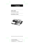
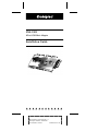
This figure identifies the major AVA-1505 components, and the table describes each component.
1
Location
Description
J11
J51
J61
F1
RN1, RN2, RN31
U3
Jumper Block
50-pin Internal SCSI Connector
DB25 External SCSI Connector
Fuse
Terminators
AIC-6360 PIO Chip
Pin 1 is marked by 1 on the board.
3 Default Settings
The AVA-1505 is designed to operate as shipped in
most AT-class computers. The default settings are
Parameter
Default Setting
SCSI Disconnection 1
SCSI Address 1
SCSI Parity 1
Terminators
Terminator Power
Interrupt Channel 2
AT Port Address 2
Enabled
7
Enabled
Installed
Supplied by host adapter
11
340h-35Fh
1
These
2
values are set by the software (see Section 6, Software Installation).
See Section 8, Jumper Block Settings, to learn how to change these settings.
1
A
AAAAAAAAAAAAAAAAAAAAAAAAAAAAAAAAAAAAAAAAAAAAAAAAAAAAAA
AA
A
AA
Document Title
A
AA
A
AA
A
AA
Part
Number:
510533-00,
Rev.
A
A
AA
A
AA
A
AA
Print Spec Number: 492410-00
A
AA
A
AA
A
Current Date: 1/24/94
ECN Date: 2/1/94 AA
A
AA
AAAA
A
AAAA
AAAA
AAAA
AAAA
AAAA
AAAA
AAAA
AAAA
AAAA
AAAA
AAAA
AAAA
AAAAAAAAAAAAAAAAAAAAAAAAAAAAAAAAAAAAAAAAAAAAAAAAAAAAAA
A
AA