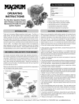
1
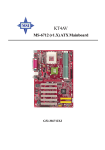
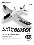
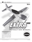
Includes Hitec Focus 3 Radio System and Wattage ESC Preinstalled!
INSTRUCTION MANUAL
Specifications:
●
●
●
Product Part Number 128424
●
●
Wing Span: 72 inches
Wing Area: 505 square inches
Length: 34.5 inches
Weight Ready-to-Fly: 2.75 pounds
Wing Loading: 12.6 ounces per square foot
IMPORTANT
The Wattage Thermalaire EP RTF is intended for individuals 12 years of age or older. Children under
12 years of age should always be accompanied by an adult when either assembling or flying the
airplane.
SAFETY WARNING
This R/C airplane is not a toy! If misused, it can cause serious bodily injury and/or damage to property. Fly only in open
areas and preferably at a dedicated R/C flying site. We suggest having a qualified instructor carefully inspect your
airplane before its first flight. Please carefully read and follow all instructions included with this airplane, your radio
control system and electronic speed control.
The Wattage Thermalaire EP RTF is distributed exclusively by Global Hobby Distributors 18480 Bandilier Circle, Fountain Valley, CA 92728
All contents copyright © 2001, Global Hobby Distributors Version V1.0 November 2001
For more cool and exciting Wattage products, visit our website at http://watt-age.globalhobby.com
1
Thank you for purchasing the new Wattage Thermalaire EP RTF and welcome to
the sport of radio control flying. Before completing the final assembly of your
new airplane, please carefully read through this instruction manual in its entirety.
Doing so will ensure success the first time around!
The Thermalaire EP RTF is the perfect airplane for both beginners and more experienced fliers alike. Beginners will
appreciate the Thermalaire's quick, easy assembly and forgiving slow-speed flight characteristics. More experienced
flyers will appreciate the Thermalaire's great flight qualities and quality balsa construction. Because of its size and
electric motor, the Thermalaire can be flown almost anywhere, too.
Thermalaire EP RTF Features:
●
●
●
●
●
●
●
All wood construction
Factory-covered in real iron-on covering material
Screwdriver-simple assembly - no glue required
Molded canopy is factory installed
Includes a factory-installed electric motor and low-drag folding propeller
Factory-installed Hitec Focus III AM radio system with Wattage IC-380 Super ESC
Final assembly is quick and easy. Only simple tools are required.
WARNING
The Hitec Focus III AM radio system (transmitter & receiver) included with the Thermalaire EP RTF operates on the
72Mhz frequency band for aircraft use only. By Federal FCC regulations it is illegal to use the included radio system
(transmitter & receiver) for any other use than operating R/C aircraft. Use in ground vehicles is strictly prohibited.
Each Hitec Focus III AM radio system comes with crystals and stickers on the back of the transmitter and on the
receiver showing which frequency the radio operates on within the 72Mhz band. No two radio systems can operate
nearby each other if they are on the same frequency.
The transmitter is a powerful device that transmits its signal farther than you can see your airplane. For this reason we
suggest checking around to make sure there are no other flyers or flying sites near you that you can't see. This will
prevent you from interfering with other flyers who might be on the same frequency as you. You can purchase transmitter and receiver crystals separately and change them if someone else nearby is on the same frequency as you.
FOR YOUR INFORMATION
To make your modeling experience totally enjoyable, we recommend that you get experienced, knowledgeable help with
assembly and during your first flights. Your local hobby shop has information about flying clubs in your area whose
membership includes qualified instructors. If there is no hobby shop in your area, we recommend that you contact the
AMA at the address below. They will be able to help you locate a flying field near you.
Academy of Model Aeronautics
5151 East Memorial Drive
Muncie IN 47302-9252
(800) 435-9262
www.modelaircraft.org
When learning to fly model airplanes we strongly suggest seeking out a local model airplane flying
club in your area.
2
Need help or have any questions? Call us at 1-714-963-0329 or send us an email at [email protected]
Section 1: Parts Identification
Before beginning assembly, remove the different parts from the box and use the photos below to verify that your kit
contains all of the correct parts. If your kit is missing a part, or if any parts appear to be damaged, please contact us
using the information below:
Wattage Customer Service
18480 Bandilier Circle
Fountain Valley CA 92728
Phone (714) 963-0329
Fax (714) 964-6236
Email: [email protected]
Wing Set
Fuselage Set
Horizontal & Vertical Tail Set
Clear Tape
Transmitter
Decal Sheet
Receiver
Velcro®
Steel Wing Joiners
Pushrod Set
Not Pictured: 2mm x 10mm Wood Screw (1)
For more cool and exciting Wattage products, visit our website at http://watt-age.globalhobby.com
3
Section 2: Our Recommendations
This section lists the items you will need to fly your new Thermalaire EP RTF. As you can see, there's not much to it!
●
Trinity "8 Pack" AA Alkaline batteries for the Transmitter - Part # 837801
●
Trinity 7 Cell Amp Max Sport Battery Pack - Part # 842010
●
Promax Black Widow AC/DC Peak Charger - Part # 350360
●
Large Flat Blade & Small Phillips Head Screwdrivers
●
Adjustable Wrench
●
Pair of Scissors
If you should have any trouble with any of the steps listed in these instructions, we have provided a Troubleshooting
Guide on page # 25. The troubleshooting guide is provided to help you find a quick and immediate resolution to any
number of problems that might occur. If you cannot solve a problem using the troubleshooter, or if you have any other
questions or concerns, please contact us using the information below:
Wattage Customer Service
18480 Bandilier Circle
Fountain Valley, CA 92728
Phone (714) 963-0329
Fax (714) 964-6236
E-mail: [email protected]
REPLACEMENT PARTS
Eventually you may need to purchase replacement parts for your airplane. For your convenience, we have listed on
page # 27 the replacement parts that are available for purchase.
FOR YOUR CONVENIENCE
We have included a glossary of terms on page # 25. Check it out if you come across any terms that are unfamiliar to you.
We know you're excited to get your new Thermalaire EP RTF flying, but take your time. Taking your time will ensure the
best possible success and fun.
4
Need help or have any questions? Call us at 1-714-963-0329 or send us an email at [email protected]
Section 3: Assembling Your Thermalaire EP RTF
Step 1: Installing the Transmitter Antenna
❑ Line up the threaded end of the antenna with the
antenna mount in the top of the transmitter.
❑ Slide the end of the antenna down into the antenna
mount.
❑ Thread the antenna into the antenna mount and tighten
it very lightly.
Do not overtighten the antenna or you could damage
the transmitter.
Step 2: Installing the Transmitter Batteries
❑ Remove the battery cover from the bottom of the
transmitter by pushing out with your thumb at the mark
on the cover.
For more cool and exciting Wattage products, visit our website at http://watt-age.globalhobby.com
5
❑ Carefully remove the battery holder from the
transmitter.
❑ Install 8 fresh AA Alkaline batteries into the battery
holder, being careful to watch that the polarity is correct
for each battery.
❑ Slide the battery holder back into the transmitter,
making sure that the electrical contacts on the end of the
battery holder match the contacts inside the transmitter.
❑
6
Push the battery cover back into place until you hear it "click" into position.
Need help or have any questions? Call us at 1-714-963-0329 or send us an email at [email protected]
Step 3: Charging the Flight Battery
WARNING
Before charging the flight battery, please read and completely understand the operating instructions that were provided
with your battery charger. Failure to follow those guidelines could result in injury to yourself or damage the charger
and/or battery pack.
❑
Connect the power leads from your charger to its power source.
❑ Plug the flight battery connector into the battery
charger connector. When plugged in properly you should
hear the connectors "click" together.
Note that the plugs can be plugged in only one way.
IMPORTANT
We strongly suggest periodically checking the temperature of the flight battery during charging. If the battery gets hot, it
is fully charged and should be removed from the charger immediately.
❑
After charging is completed, remove the battery from the charger, then remove the charger from its power source.
You must squeeze the tab on the charger connector to be able to pull the two connectors apart.
Step 4: Assembling the Wing Panels
❑ Carefully line up one of the longer steel wing joiners
with the forward hole in one end of the center wing panel.
The center wing panel is the longest of the three wing
panels.
For more cool and exciting Wattage products, visit our website at http://watt-age.globalhobby.com
7
❑
Push the wing joiner into the hole until it stops.
❑ Push one of the shorter wing joiners into the rear hole
using the same technique.
❑ Carefully line up the two holes in the matching outer
wing panel with the exposed ends of the wing joiners.
❑
Carefully push the two wing panels firmly together as shown.
The wing panels should fit tightly together.
8
Need help or have any questions? Call us at 1-714-963-0329 or send us an email at [email protected]
❑ With both wing panels pushed firmly together, apply
a strip of clear tape to the top of the wing joint.
❑ Use scissors to trim the ends of the tape flush with
the wing, then turn the wing over and apply a strip to the
bottom of the joint.
The tape will keep the wing panels from pulling apart
during flight. Do not omit this procedure.
❑
Repeat the previous procedures to install the second outer wing panel to the center wing panel.
Step 5: Installing the Tail Assembly and Pushrods
❑ Insert the Z-Bend in one pushrod wire into the third
hole out from the base of the elevator control horn.
IMPORTANT
Install the Z-Bend so that the longer portion of the pushrod
wire faces toward the middle of the horizontal tail as
shown.
❑ Turn the horizontal tail right-side up and carefully
slide the plain end of the pushrod wire into the pushrod
exit hole in the right side of the fuselage.
❑ Push the stabilizer forward until it rests on top of the
mounting platform on the fuselage.
Fuselage shown upside down for photo clarity.
For more cool and exciting Wattage products, visit our website at http://watt-age.globalhobby.com
9
❑ Push the horizontal tail back far enough to allow
room to slide the end of the pushrod wire through the
adjustable servo connector.
❑ Carefully slide the end of the pushrod through the
small hole in the side of the connector.
If the pushrod wire won't slide through, loosen the
set screw on top of the connector.
IMPORTANT
Don't tighten the set screw at this time.
❑
Remove the two hex nuts and two flat washers that are preinstalled on the vertical tail mounting studs.
❑ Remove the nylon rudder control horn using a phillips screwdriver to remove the two machine screws. Set the
control horn, backplate and screws aside for now.
IMPORTANT
The control horn must be removed to install the vertical tail.
❑ Line up the two tail mounting studs in the vertical
tail with the two holes in the horizontal tail.
❑ Line up the assembly and carefully push the vertical
tail down until the mounting screws extend out the bottom
of the fuselage.
You may have to move the horizontal tail slightly to
allow the mounting screws to pass through easily.
10
Need help or have any questions? Call us at 1-714-963-0329 or send us an email at [email protected]
❑ Turn the fuselage upside down and slide one flat
washer onto each vertical tail mounting stud.
❑ Thread one hex nut onto each mounting stud and
tighten them both finger-tight.
❑ Use an adjustable wrench to tighten the hex nuts
firmly to draw the tail assembly down into place.
The tail assembly should be firmly tightened down
into place.
❑ Insert the Z-Bend in the remaining pushrod wire into
the third hole out from the base of the rudder control horn
that you removed previously.
IMPORTANT
Install the Z-Bend so that the longer portion of the pushrod
wire faces toward the right side of the control horn as
shown.
❑ Slide the plain end of the pushrod wire into the
pushrod exit hole in the left side of the fuselage.
❑ Slide the plain end of the pushrod wire through the
small hole in the side of the pushrod connector.
If the pushrod wire won't slide through, loosen the
set screw on top of the connector.
IMPORTANT
Don't tighten the set screw at this time.
For more cool and exciting Wattage products, visit our website at http://watt-age.globalhobby.com
11
❑ Reinstall the control horn to the rudder using the two
machine screws and the nylon backplate you removed
previously. Tighten the machine screws snug, but not so
tight that you crush the wood.
Note that the longer portion of the pushrod wire
should come out on the top side of the control horn.
Step 6: Applying the Decals
❑ Using a pair of scissors, cut out each of the decals
along its outer edges.
❑ Remove the protective backing from the decals and
carefully apply the decals to the airframe.
Use the box cover photos as a reference for the decal
locations.
12
Need help or have any questions? Call us at 1-714-963-0329 or send us an email at [email protected]
Step 7: Installing the Flight Battery
❑
Pull the two pieces of Velcro® apart.
❑ Remove the protective backing from one piece of
Velcro®.
❑ Apply that piece of Velcro® to the middle of the
battery as shown.
❑ Remove the protective backing from the remaining
piece of Velcro®.
❑ Apply the piece of Velcro® to the upper portion of
the battery tray as shown.
❑ Set the flight battery in place on top of the battery
tray.
The Velcro® should be facing down and the battery
plug should be toward the top of the fuselage.
❑ Push the flight battery down as far forward as it
will go. The Velcro® will keep it from sliding around
or backing out during flight.
For more cool and exciting Wattage products, visit our website at http://watt-age.globalhobby.com
13
WARNING
Before proceeding, check to make sure the on/off switch
on the side of the fuselage is in the "off" position.
❑ Plug the connector on the flight battery into the
connector that is inside the fuselage. When plugged in
properly you should hear the connectors "click".
Note that the plugs can be plugged in only one way.
Step 8: Installing the Receiver
❑ Carefully remove the hatch cover from the bottom of
the fuselage by pulling up on the front of the cover.
❑ Plug the elevator, rudder and ESC leads into their proper slots in the receiver. The ESC plugs into slot 3, the rudder
plugs into slot 1 and the elevator plugs into slot 2.
❑ Push the wires down into the fuselage and set the
receiver on top of the preinstalled wooden rails inside
the hatch.
Make sure the receiver antenna is toward the back of
the fuselage.
14
Need help or have any questions? Call us at 1-714-963-0329 or send us an email at [email protected]
❑ Push the end of the antenna through the predrilled
hole in the back of the hatch cover.
Push the antenna through from the bottom of the hatch
cover.
❑ Pull the antenna through the hole and set the hatch
cover back into place.
❑ Install and tighten the 2mm x 10mm wood screw to
secure the hatch cover to the fuselage.
IMPORTANT
The hatch cover will hold the receiver securely in place.
❑
Pull the antenna taut (but not overly tight) and use a small piece of clear tape to secure it to the back of the fuselage.
WARNING
Do not cut off the excess antenna. Let the excess hang behind the airplane. If you cut the antenna it will greatly reduce
the range of the receiver and you will lose control of the airplane.
Step 9: Connecting the Control Surfaces
❑ Turn on the transmitter. The green LED should light
up.
IMPORTANT
Before turning on the transmitter, check to make sure the
switch on the side of the fuselage is "off."
This will prevent unexpected radio signals from
interfering with your radio system.
For more cool and exciting Wattage products, visit our website at http://watt-age.globalhobby.com
15
❑ Carefully adjust the left and right and the up and down
control trim levers until they are both centered as shown.
❑ Double check to make sure the throttle control lever
is in the "off" position as shown.
❑ Push the switch on the side of the fuselage to turn on
the airborne system (ESC, receiver and servos). You
should hear the servos center themselves.
Double-check that the throttle lever is set to "off."
This will prevent the propeller from spinning when you
turn on the airborne system.
WARNING
Keep clear of the propeller when turning on the airborne
system and when working the controls.
IMPORTANT
To prevent unwanted signals from interfering with the radio system, always turn on the transmitter first, followed by the
airborne system. When done flying, turn off the airborne system first, followed by the transmitter.
16
Need help or have any questions? Call us at 1-714-963-0329 or send us an email at [email protected]
❑ While holding the horizontal control surface even with the
horizontal tail, use a phillips head screwdriver to tighten the set
screw in the top of the adjustable servo connector.
❑ While holding the vertical control surface even with the
vertical tail, use a phillips head screwdriver to tighten the set
screw in the top of the adjustable servo connector.
Step 10: Installing the Wing
❑ Set the wing into the wing saddle and align the brass insert in the leading edge of the wing with the pin in the
fuselage's forward bulkhead.
❑
Slide the wing forward completely, making sure the brass insert slides over the pin.
❑ Insert the two nylon bolts through the two predrilled
holes in the top of the wing and thread them into the
plywood mounting block preinstalled in the fuselage.
❑ Tighten the two screws using a large flat blade
screwdriver.
WARNING
Do not overtighten the screws or you may crush the wing.
For more cool and exciting Wattage products, visit our website at http://watt-age.globalhobby.com
17
Section 4: Testing Your Thermalaire EP RTF
Step 1: Verifying Control Surface Direction
❑
Plug in and install the flight battery.
❑
Turn on the transmitter, then turn on the airborne system.
WARNING
During this step, make sure to keep the throttle control lever in the "off" position.
❑ Looking from the back of the airplane, move the transmitter
control stick completely to the left. The vertical control surface
should move left.
❑ Looking from the back of the airplane, move the transmitter
control stick completely to the right. The vertical control surface
should move right.
18
Need help or have any questions? Call us at 1-714-963-0329 or send us an email at [email protected]
❑ Looking from the back of the airplane, move the transmitter
control stick completely back. The horizontal control surface
should move up.
❑ Looking from the back of the airplane, move the transmitter
control stick completely forward. The horizontal control surface
should move down.
Step 2: Testing the Motor
WARNING: During the motor test keep everything clear
of the propeller, especially fingers and loose clothing.
❑ While holding the airplane upright in the air with the
propeller pointing away from you, slide the throttle control lever completely to the right. The propeller should
spin at a high rate of speed.
❑ When finished with the test, slide the throttle control
lever completely to the left; the motor should turn off.
Turn off the airborne system, then turn off the transmitter.
For more cool and exciting Wattage products, visit our website at http://watt-age.globalhobby.com
19
Section 5: Getting Ready to Fly
Step 1: Choosing Your Flying Field
❑ The flying field you choose should be a large, open field with grass. There should not be any vehicles, buildings,
power lines, trees, large rocks - or anything else for your airplane to crash into.
Step 2: Choosing a Day to Fly
❑ Until you become a proficient flyer you should always plan on flying your Thermalaire when there's no wind. We
strongly suggest waiting for a calm day.
❑
Snap the red flag to the end of the transmitter's antenna.
❑ Hold the transmitter up at an angle. If the flag hangs down,
go ahead and fly.
There's no wind.
It's okay to fly.
❑ If the flag hangs at a 45º angle or more, don't fly. Wait for
a calmer day.
There's too much wind.
Wait for a calmer day to fly.
20
Need help or have any questions? Call us at 1-714-963-0329 or send us an email at [email protected]
Step 3: Range Testing the Radio System
❑
Plug in and install the flight battery.
❑
Turn on the transmitter, double-check that the throttle lever is in the "off" position, then turn on the airborne system.
❑
Set the Thermalaire on the ground.
❑
With the transmitter's antenna fully collapsed, move the control stick back and forth to check the controls.
❑ Walk approximately 50ft. from the airplane and move the control stick back and forth. Check to make sure that the
airplane's controls are moving smoothly at this distance. You may need a friend to help you with this step.
If the Thermalaire does not range check, don't fly! Please refer to the troubleshooting guide on page # 28.
Section 6: Flight Tips and Warnings
Before flying your Thermalaire for the first time, please read these flight tips and warnings carefully.
Check before every flight to ensure that the batteries in the transmitter are working properly. When the red LED
begins to flash it's time to change the batteries.
●
Before recharging the flight battery, let the motor run until the flight battery is completely drained. This will ensure
you don't overcharge the battery.
●
●
Do not begin to charge the flight battery if it is hot. Wait for the battery to cool before recharging it.
●
Never leave the flight battery plugged into the airplane unless you are flying or testing the controls.
●
Before flying, always double-check that you've extended the transmitter antenna completely.
Before each flight, do a quick motor test to make sure that the motor is producing full power. If it isn't the flight battery
may not be fully charged. Do not charge a completely drained flight battery longer than 30 minutes or damage to the flight
battery may occur.
●
When you fly, orientate yourself so that the sun is at your back. Don't fly directly into the sun or you won't be able to
see your airplane.
●
Separate battery packs can be purchased and charged before going to the flying field. An extra flight battery will
double your flight time.
●
●
Do not fly in high winds, otherwise the Thermalaire will be difficult to control and a crash will likely occur.
Do not fly your airplane if another airplane is on the same frequency as you. The frequency and channel number are
printed on the back of the transmitter.
●
The transmitter is a powerful device that transmits its signal farther than you can see your airplane. For this reason we
suggest checking around to make sure there are no other flyers or flying sites near you that you can't see. This will prevent
you from interfering with other flyers who might be on the same frequency as you.
●
●
Always be conscious of the spinning propeller. Be careful not to allow loose clothing to be drawn into the propeller.
●
If you're under 12 years of age we suggest you fly while accompanied by an adult.
●
Never attempt to disassemble any of the Thermalaire's components, especially the transmitter and receiver.
●
Do not allow any of the components to get wet or electrical damage may occur.
For more cool and exciting Wattage products, visit our website at http://watt-age.globalhobby.com
21
Section 7: Flying the Thermalaire EP RTF
Control Stick Overview:
Control Stick Right
-
Airplane Turns Right
Control Stick Left
-
Airplane Turns Left
Control Stick Back
-
Airplane Climbs
Control Stick Forward
-
Airplane Descends
Step 1: Hand Launching
❑ You should always launch the Thermalaire into the wind. Determine wind direction by tossing some blades of grass
into the air and watching which direction they fall.
❑
Turn on the transmitter, then the airborne system.
❑ In your throwing hand grasp the airplane from the base of the fuselage, directly below the center of the wing, and hold
it up above shoulder level.
❑ While keeping clear of the propeller, push the throttle control lever all the way to the right. The motor should be at
full power and the propeller should be spinning at a high rate of speed.
❑
With the motor at full power, firmly toss the airplane straight ahead and level. Do not throw it up or down.
❑ After launching the airplane, fly straight ahead and level for about 20 - 30 feet to allow the airplane to build up
flying speed. You may need to hold a slight amount of back stick to keep the airplane level and prevent it from
descending.
WARNING
Do not try to climb until after the airplane picks up sufficient airspeed. Climbing too steeply too quickly will result in a
stall and crash.
Step 2: Flying
❑ After you've launched the Thermalaire and the flying speed has picked up, keep the motor running at full power and
apply a small amount of back stick to put the airplane into a shallow climb.
Be careful not to over-control. You don't need to move the control stick very much to make the airplane do what you
want it to. Moving the control stick too much will only result in the airplane pitching and rolling severely.
❑
After reaching about 80 - 100 feet of altitude you should start making shallow turns to keep the airplane near you.
WARNING
Don't fly the Thermalaire too far away from you or you could lose sight of it.
22
Need help or have any questions? Call us at 1-714-963-0329 or send us an email at [email protected]
❑ To turn the Thermalaire, gently move the control stick in the direction you want the airplane to go and hold it for a
second or two. After the airplane starts turning in the direction you want it to, let go of the control stick.
Because of the polyhedral wing design, the wing will level itself from a shallow turn - after releasing the control stick.
If you get into too sharp a turn or if you want to level the wings sooner, move the control stick in the opposite direction that
you turned. When the wing levels off, release the control stick. Remember, don't over-control.
WARNING
The longer you hold the control stick over, the tighter radius the airplane will turn in. We recommend gentle turns until
you are proficient with the flight characteristics of the airplane.
If the airplane always turns one direction or the other, use the sliding trim lever (as described on page # 16) to make
the airplane fly level.
❑ The Thermalaire's altitude is controlled by moving the control stick forward and back. If you want the airplane to
climb, gently pull back on the control stick. If you want the airplane to descend, gently push forward on the control stick.
IMPORTANT
To make it easier to learn to fly, we suggest reducing the throttle to slow the airplane down. It is easier to learn to fly when
the airplane is flying slower because you have more time to react to what you're doing.
When going into a turn, the airplane will have a natural tendency to lose some altitude. Unless you want to descend,
you should gently pull back on the control stick to keep the airplane level during the turn. The steeper the turn the more
altitude the airplane will lose.
IMPORTANT
If you are flying in a light wind, the airplane will tend to climb as you turn into the wind. In this instance, you will need
to level off the airplane by pushing forward gently on the control stick. When you turn down-wind, the airplane will have
a natural tendency to lose altitude. In this instance, you should pull back gently on the control stick.
Step 3: Landing
IMPORTANT
All landings should be made flying straight into the wind with the wing level.
❑ Move the throttle control lever completely to the left to turn off the motor. At this point the airplane will begin to
descend. Allow the airplane to gradually descend. If the airplane seems to be descending too fast, gently pull back on the
control stick to make the airplane slow its descent. This will also slow the airplane down. Once the airplane has slowed
down and is descending gradually, release the control stick and allow the airplane to continue its descent. Once the
airplane is about 15 feet off the ground make sure the wing is level and continue a shallow descent. Just before touchdown, gently pull back on the control stick to level the airplane with the ground for landing.
If you need to turn the airplane while flying slowly, make shallow, gentle turns. Do not turn too steeply.
WARNING
Be careful not to allow the airplane to get too slow during landing. If the airplane gets too slow, it could stall and crash.
It's better to land at a higher speed than normal until you get more familiar with the airplane.
For more cool and exciting Wattage products, visit our website at http://watt-age.globalhobby.com
23
Section 8: Basics of Thermal Flying
The following is intended for those pilots who have mastered flying the Thermalaire EP. Thermal flying is by far the most
difficult aspect of glider flying; however, it can be the most rewarding. For more information on thermals, check your
local library or the Internet. There are many books and articles available that detail what thermals are and how they work.
Basically speaking, thermal lift is created by areas of warm air rising from the ground. As the ground heats up from the
warmth of the sun, the air above it will begin to warm. This is especially true over terrain such as a freshly plowed field
or a paved parking area. As the air heats, it will begin to rise and allow cooler air to move in to replace it. This air, in turn,
will heat up, rise, and you will get a continuous current of rising air.
Thermal flying is truly an art but there is also a good amount of luck involved in finding the perfect thermal. There are
ways to hone your skills so that you can become an artist in flying thermals rather than remain a hopeful novice who
blunders into them by accident. The following are some keys to begin the process of becoming a better thermal pilot.
The first key is to become very familiar with the way the Thermalaire flies. Knowing the way it responds when entering
and exiting thermal lift is essential. There are things you will notice as you fly the Thermalaire more and more. You need
to be familiar with the airplane so that you can recognize when it is flying normally and when it is responding to up or
down air. It is very hard for the novice to tell what is happening to a new airplane in regards to the air. He or she is
uncertain if the movement is due to something that the pilot did or due to air movement. You want the airplane to be
properly trimmed out so that it flies smooth and stable and so you know how it responds when you turn. Polyhedral wing
designs, like those on the Thermalaire, try to remain stable and are easier for the novice to fly than straight wing planes
(i.e., wings with no dihedral) and, more importantly, are responsive to hitting the side of a thermal more dramatically than
straight wing planes do.
You will seldom hit a thermal straight on in flight. More often you will hit the side of the thermal and it will lift one wing
more and literally throw your airplane away from the lift. When your airplane should otherwise be flying level, watch for
a sudden lift of a wing tip and turn the airplane into that area. There is a good chance that you hit the side of a thermal and
it pushed you away—into the air next to the thermal. Having located a thermal, turn into it and start circling to locate the
area of strongest lift. Tighten up the circle to get the maximum rate of climb.
Think of the air as water. No wind is a calm lake. A breeze is a slow moving stream and a heavy wind is a raging river.
Often, a pilot hits some lift, starts circling, then goes up and up and stays right in the same spot circling. Then he starts
coming down and doesn’t understand why. On a calm day, once you hit lift you can circle right there as it isn’t going
anywhere but up. It may die after a short time, but that happens. With wind, picture your lift as an escalator going
downwind at the same rate as the wind is blowing. You hit it and start to circle and you go up, but you must have your
circling go downwind at the same speed as the wind to stay on the escalator. The lift is moving and if you don’t go with
it you lose it.
Watch the tail of the airplane bounce up to see if you are hitting lift. When you fly into a thermal it kicks the tail up and
thus points the nose down. Despite this "dive" position your airplane may actually be going up in the lift. It depends on
the strength of the thermal. That "up tail" is a sign to watch for in thermal spotting.
Use your visual keys and work on your skills so you can become accustomed to thermal flying. Don't forget to watch the
birds, too. If you see birds with their wings stretched out, circling high above, you can be sure they are in a thermal.
Launch your airplane and head in that direction. They won't mind you joining them in the fun!
24
Need help or have any questions? Call us at 1-714-963-0329 or send us an email at [email protected]
Section 9: Troubleshooting Guide
This troubleshooting guide has been provided to help you diagnose and solve most problems that you may encounter
with your Thermalaire EP RTF. Most problems encountered can be solved by carefully following the problem-causesolution sections below. If you cannot solve the problem using this troubleshooting guide, please feel free to contact us
at the address or phone number listed on page # 3.
PROBLEM
CAUSE
SOLUTION
1) Transmitter does not turn on
A) Transmitter batteries are depleted
B) Transmitter batteries are not installed properly
A) Replace batteries with new ones
B) Reinstall the batteries, double checking
the polarity
2) Tail servos do not work
A) Flight battery is depleted
B) Flight battery is not plugged in or is loose
A) Recharge flight battery
B) Check that the flight battery is plugged
in firmly
C) A crash has damaged an internal component
C) Refer to the warranty information on the
back cover of this manual
A) Flight battery is not plugged in
B) Flight battery is depleted
C) Loose connection between the motor and ESC
and/or the ESC and the receiver
D) A crash has damaged an internal component
A) Plug in flight battery
B) Recharge flight battery
C) Make sure all connections are secure
A) You may be flying in too much wind
B) The control surfaces are out of trim
A) Fly when it is calm outside
B) Center the control surfaces by adjusting
the pushrods as described on page # 17
C) Land and recharge the flight battery
D) Replace batteries with new ones
E) Be careful not to over-control. Apply
only small, gentle control inputs
3) Motor does not turn on
4) The airplane is difficult
to control
C) The flight battery is depleted
D) Transmitter batteries are depleted
E) You are over-controlling
D) Refer to the warranty information on the
back cover of this manual
5) The airplane always
turns to the left or right
A) The left/right trim lever is out of adjustment
A) Adjust the trim lever on the transmitter
until the airplane flies straight
without control input
6) The airplane always climbs
or descends
A) The up/down trim lever is out of adjustment
A) Adjust the trim lever on the transmitter
until the airplane flies level without
control input
7) Cannot trim the airplane
using the trim levers
A) Control surfaces are too far out of trim
A) Readjust the pushrods as described on
page # 17
8) The propeller hits the front
of the cowling
A) Propeller blades fold back when motor is off
A) This is normal. It reduces drag while
gliding
9) The radio system fails the
range check
A) Transmitter batteries are low or depleted
B) The flight battery is low or depleted
C) The receiver antenna is not extended outside
the fuselage
D) You're too far away from the model during the test
E) The radio system is not functioning properly
A) Replace batteries with new ones
B) Recharge the flight battery
C) Extend the receiver antenna so it hangs
outside of the fuselage
D) Range test 50 feet away from the model
E) Refer to the warranty information on the
back cover of this manual
10) The flight battery gets hot
during charging
A) It's normal for the battery to be warm. If it's hot to
the touch, it's overcharged
A) Remove the battery from the charger
immediately
For more cool and exciting Wattage products, visit our website at http://watt-age.globalhobby.com
25
Section 10: Glossary of Terms
Adjustable Servo Connector: Provides a quick and
easy method to secure the pushrod wire to the servo horn.
A set screw in the connector makes adjusting the pushrod
very easy.
Battery Charger: Connects to a 12 volt source and
charges the flight battery to full capacity.
Control Stick: The stick on the transmitter that you
move. One stick moves both right and left and up and
down to control the airplane.
Pushrods: They connect the control surfaces to the
servos, transferring the movement of the servos directly
to the control surfaces.
Receiver: The part of the radio system that receives the
signals from the transmitter.
Servo: The part of the radio system that produces the
movement necessary to move the control surface. The
servo includes a small motor, gears and a circuit board.
Control Horn: Mounted to the control surface, it gives
an attachment point for the Z-Bend in the pushrod wire.
Servo Horn: Made out of plastic or nylon, it attaches to
the servo output shaft. The pushrod and/or servo connector are then attached to the servo horn.
Control Surfaces: The surfaces on the tail assembly
that pivot to make the airplane turn right and left and pitch
up and down.
Stall Speed: The speed at which air stops moving fast
enough over the surface of the wing to keep the airplane
flying.
Dihedral: The upward angle of each wing panel. Dihedral creates more stability that makes learning to fly easier.
Transmitter: The part of the radio system that you
control. It transmits the control inputs to the receiver,
which transfers that information to the servo and motor controller.
Flight Battery: Comprised of individual battery cells,
the flight battery is mounted inside the airplane and powers the motor, receiver, ESC and servos.
Horizontal Tail: The wing-like surface on the back of
the airplane that is parallel with the wing. The horizontal
tail provides stability to the airplane.
Motor Controller (ESC): The motor controller controls the speed of the motor. The Thermalaire's motor
controller is proportional with the throttle lever so you
can reduce or increase speed smoothly.
Trim Lever: A sliding lever on the transmitter that
allows you to make small adjustments to the control
surfaces from the transmitter.
Vertical Tail: The wing-like surface on the back of the
airplane that is perpendicular to the horizontal tail. The
vertical tail provides stability to the airplane.
Z-Bend: A "Z Shaped" bend in pushrods that is used to
connect the pushrods to the control surfaces.
Polyhedral Wing: A wing design that utilizes two separate points of dihedral. Polyhedral wings have a flat center
panel and two outer panels with dihedral. The polyhedral
wing design is perfect for beginners because it makes the
airplane very stable and easy to control.
26
Need help or have any questions? Call us at 1-714-963-0329 or send us an email at [email protected]
Section 11: Replacement Parts
Listed below are the replacement parts that are available for your Wattage Thermalaire EP RTF. The part numbers for
each part are provided for ordering convenience. Replacement parts are available through your local authorized Wattage
dealer or directly from us.
First, Visit Your Local Dealer:
To locate the Global dealer nearest you, please call us at (714) 963-0133 or visit our
dealer directory on the Internet at www.globalhobby.com/where2buy.htm
or Order Directly From Us:
Wattage Customer Service
18480 Bandilier Circle
Fountain Valley, CA 92728
Phone (714) 963-0329
Fax (714) 964-6236
Instruction Manual
-
150540
Hardware Set
-
150545
Wing Set
-
150541
Electric Motor
-
150546
Fuselage Assembly
-
150542
Folding Propeller
-
150547
Tail Assembly Set
-
150543
Decal Sheet
-
150548
Canopy
-
150544
IC-380 Super ESC
-
128472
For more cool and exciting Wattage products, visit our website at http://watt-age.globalhobby.com
27
Warranty Information - Please Read
Your Thermalaire EP RTF is warrantied against manufacturer defects in materials and workmanship for a period of 90
days from the date of purchase. Warranty service will be provided within 90 days of the date of purchase only if you are
able to provide the original (or a copy of the original) dated sales receipt.
Special Notice
The radio control system preinstalled in your Thermalaire EP RTF is manufactured and warrantied by Hitec/RCD North
America. This includes the transmitter, receiver and servos. Do not return the radio system to Wattage Customer Service.
It must be removed from the airplane and returned to Hitec/RCD at the address shown:
Hitec/RCD, Inc.
Attn: Customer Service Center
12115 Paine Street
Poway, CA 92064
Warranty Service
Before returning your Thermalaire EP RTF for warranty consideration, the status of the unit must be within the guarantee
as stated above. Do not return your airplane to the place of purchase. They are not authorized or equipped to perform
warranty work on Wattage products. When requesting warranty service, please observe the following:
●
Crash damage will not be covered under warranty. Do not request warranty service for a crash-damaged product.
●
If you are requesting warranty on anything other than just the radio control system, always send your airplane
complete with the transmitter. Please unplug and/or remove the batteries both from the transmitter and the airplane
before returning it. We like to have the airplane complete so it can be thoroughly tested before returning it to you.
●
If you are requesting warranty service for only the radio system do not send the radio system or the airplane to us.
Remove the radio system from the airplane and return it to Hitec/RCD for warranty consideration. See Special
Notice above.
●
Include a note detailing the problem or service you are requesting. Service cannot be provided without this information.
Include your daytime phone number, shipping address and/or email address in the event we need more details
pertaining to the service requested.
●
If your airplane is out of the warranty period you may request an estimate of services at the time you return your
airplane for service. An omission of this request implies permission for Wattage to service your airplane at our
discretion.
●
Include a method of payment for any service charges.
●
Send the unit to us by United Parcel Service, Federal Express or by Insured Mail. Postage is non-refundable. Send
your package to:
Wattage Customer Service
18480 Bandilier Circle
Fountain Valley, CA 92728
Phone (714) 963-0329
Fax (714) 964-6236
Email: [email protected]
28
Need help or have any questions? Call us at 1-714-963-0329 or send us an email at [email protected]