1
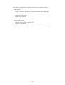
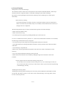
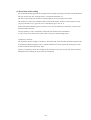
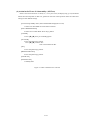
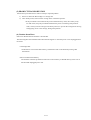
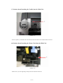
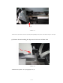
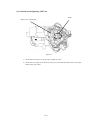
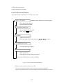
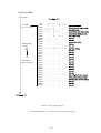
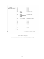
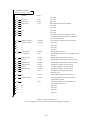
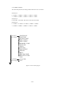
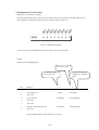
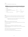
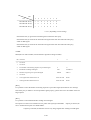
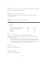
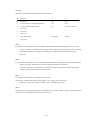
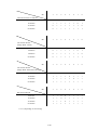
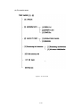
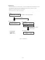
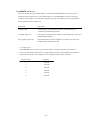
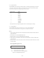
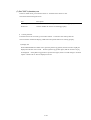
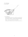
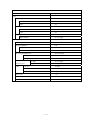
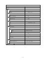
FAXPHONE B95
SERVICE
MANUAL
Canon
Copyright 2004, Canon U.S.A. This technical publication is the proprietary and confidential information of Canon U.S.A. which
shall be retained for reference purposes by Authorized Service Facilities of Canon U.S.A. Its unauthorized use is prohibited.
FAXPHONE B95
Service Manual
REVISION 0
HY8-10B0-000
COPYRIGHT 2004 CANON INC. FAXPHONE B95 AUGUST. 2004
Scope
This manual has been issued by Canon Inc., to provide the service technicians of this product with the
information necessary for qualified persons to learn technical theory, installation, maintenance, and repair of
products. The manual covers information applicable in all regions where the product is sold. For this reason, it
may contain information that is not applicable to your region.
Revision
This manual could include technical inaccuracies or typographical errors due to improvements or changes made
to the product. When changes are made to the contents of the manual, Canon will release technical information
when necessary. When substantial changes are made to the contents of the manual, Canon will issue a revised
edition.
The following do not apply if they do not conform to the laws and regulations of the region where the manual or
product is used
Trademarks
Product and brand names appearing in this manual are registered trademarks or trademarks of the respective
holders.
Copyright
All right reserved. No part of this manual may be reproduced in any form or by any means or translated into
another language without the written permission of Canon Inc., except in the case of internal business use.
Copyright 2004 by Canon Inc.
CANON INC.
5-1 Hakusan 7-Chome, Toride-city, Ibaraki 302-8501, Japan
I. MANUAL OUTLINE
This manual is divided into three parts, and contains information required for servicing the product.
Part 1: Maintenance
Information on maintenance and troubleshooting of the product.
Part 2: Technical Reference
New technology and technical information of the product.
Part 3: Appendix
Schematic and Specifications.
Reference
This manual does not provide sufficient information of disassembly and reassembly procedures. Refer to the
graphics in the separate Parts Catalog.
II. Table of Contents
Page
1-1
1-1
1-1
1-2
1-2
1-2
1-2
1-3
1-5
1-9
1-9
1 - 23
1 – 30
1 - 38
Part 1: Maintenance
1. Maintenance
1.1 Adjustment, Periodic Replacement Parts, Periodic Maintenance, Replacement of
Consumables by Service Engineer
1.2 Customer Maintenance
1.3 Product Life
1.4 Special Tools
2. LIST OF ERROR DISPLAY
2.1 Troubleshooting Index
2.2 Errors shown on display (judgment criterion: check diplay)
2.3 Errors not shown on display
3. Repair
3.1 Caution when replacing service parts
3.2 Service Switches
3.3 Explanation of service data
3.4 Test Function
Page
Part 2: Technical Reference
2-1
1. New Technology
Page
Part 3: Appendix
3-1
3-2
1. Schematic
2. Specifications
Part 1
Maintenance
1. MAINTENANCE
1.1 Adjustment, Period Replacement Parts, Periodic Maintenance, and Replacement
Consumables by Service Engineer
(1) Adjustment
Item
When
Purpose
Adjusting gear phase
When replacing gear unit
To adjust gear phase
Resetting the ink counter
When replacing NK ABSORBER
To reset the ink counter
CS pre-scan
When replacing CS
To set scan data
Data Set
When replacing SCNT board
To initialize data and restore
When replacing CR
factory setting
Tool
When
(2) Periodic maintenance
Item
When
Purpose
Tool
When
None
(3) Periodic replacement parts
Item
When
Purpose
Tool
When
Purpose
Tool
When
Tool
Approx.
None
(4) Replacement consumables
Item
When
None
1.2 Customer Maintenance
Adjustment
Timing
Purpose
time
Print head cleaning
When print quality is
To improve nozzle conditions.
not satisfying.
BJ FAX Cartridge
When an BJ FAX
replacement
Cartridge becomes empty.
Paper feed roller
When paper does not
To clean the paper feed rollers.
feed properly.
1-1
1.3 Product Life
(1) Printer
The value from 1) - 3), whichever comes first.
1) 18,000 pages of printing
2) 18,000 pages of scanning
3) 5 years of use
(2) Print CRG (ink tank)
Approx. 900 pages of printing
*When printing Canon Fax Standard Chart No.1
1.4 Special Tools
Name
Tool No.
Purpose
Remarks
None
2. LIST OF ERROR DISPLAY
2.1 Troubleshooting Index
Use the troubleshooting index below to investigate the cause of the problem and refer to the specified page
for countermeasures.
(1) Errors shown on display (judgment criterion: check display)
When errors shown on display
Refer to 1-3 page
When errors not shown on display
Refer to 1-5 page
(2) Errors not shown on display (judgment criterion: check machine)
General errors
Refer to 1-5 page
No power
Abnormal display
Operation panel buttons do not work
No sound from speaker
Printing failure (judgment criterion: test print failure)
Paper not properly fed
Refer to 1-6 page
Paper not picket up from ASF
Printing operation abnormality
Refer to 1-6 page
Nothing is printed
Carriage motor does not move
1-2
Print quality defect
Refer to 1-7 page
Print is not clear
Blurred image or smudged print
Stain on the back of printout
Inconsistent print quality
Head cleaning required
Horizontal white streaks in black header
Scanning failure (judgment criterion: test print is OK but copy fails)
Scanning failure
Refer to 1-7 page
Document slips on the rollers
Document is not properly separated
Scanning assembly sensor broken
Abnormality in scanned image
Refer to1-8 page
Nothing printed
Vertical streaks in image
2.2 Errors shown on display (judgment criterion: check display)
(1) User error messages
Check the error message in question and take the appropriate action.
[BUSY/NO SIGNAL] (#018)
Cause: Other party machine does not respond within 55 seconds. (T0 timeout)
Countermeasure: Contact the other party and have them check the condition of their fax.
Transmit manually. In the case of an international call,
insert a pause into the programmed telephone number.
Cause: The machine’s tone/ pulse dial settings are not correct.
Countermeasure: Programme the settings according to the telephone line being used.
Cause: Other party machine is not a G3 fax.
Countermeasure: Contact the other party and have them send or receive in G3.
Cause: Other party machine is broken.
Countermeasure: Contact the other party and have them check the condition of their fax machine.
Cause: Dialled number is busy.
Countermeasure: Call again later.
1-3
[CARTRIDGE JAMMED]
Printer position correction failure
Cause: Carriage does not operate normally, for one of the following reasons.
Carriage shaft is broken/ deformed. Broken /deformed parts
Or, contact sensor unit does not return from scanning position.
Countermeasure: Replace printer assembly or contact sensor unit.
[CHECK DOCUMENT] (#001)
Cause: PAPER JAM
This message appears when the document edge sensor cannot detect the edge of the document
after the document sensor detects the presence of the document and the feeder roller rotates 360
degrees to perform one document feeding operation
Countermeasure: Clear the document jam.
[CHECK PAPER SIZE]
Cause: The size of paper set in the ASF is different from the paper size programmed in the printer.
Countermeasure: Change the printer’s PAPER SIZE setting to the correct paper size.
[CHECK PRINTER] (##332 to ##337, #343, ##345, ##346, ##348)
Cause: Printer internal failure
Countermeasure: 1) Is the BJ cartridge’s operation being hampered by jammed paper? Clear the
jammed paper.
2) Press the STOP button.
3) Reset the BJ cartridge.
4) Turn the power OFF/ ON.
5) Refer to the appropriate action for the error code.
[DATA ERROR]
Cause: SRAM data have been destroyed and a checksum error has been generated because the lithium
battery is dead or some kind of SRAM failure.
Countermeasure: 1) Perform ALL CLEAR in the service mode.
2) Replace the SCNT board.
[DOC. TOO LONG] (#003)
Cause: The document length exceeds 70cm.
Countermeasure: Make a reduced size copy of the document and send it again.
1-4
[MEMORY FULL] (#037)
Cause: A very large document has been received in memory reception and the memory is full.
Countermeasure: 1) Print out the document(s) stored in the memory and try the operation again.
2)Delete any unnecessary documents from the memory.
Cause: There are too many pages in the transmission document and the transmission memory is full.
Countermeasure: Split up the document and send it.
(2) Error codes
1) Service error code output
When service data #1 SSSW SW01 bit 0 is set to ‘1’, if a transmission ends in error, a service
error code will be output on the transmission activity report, reception results report and the error
transmission report. Also, in the event of an error, the error code will be shown on the display.
2) Error codes
Refer to ‘G3/G4 Facsimile Error Codes Service Handbook’ for details on error code causes and
countermeasures.
2.3 Errors not shown on display
(1) General errors
·No power
1) Check that the power cord is properly connected.
2) Check the connection between the SCNT board (J151) and the power supply unit.
3) Check the power supply unit fuse (F1).
4) Replace the power supply unit.
5) Replace the SCNT board.
·Abnormal display
Nothing displayed
1) Check the connection between the control panel unit and the SCNT board (J202).
2) Replace the operation unit.
3) Replace the SCNT board.
Part of the LCD does not display
1) Check the connection between the control panel unit and the SCNT board (J202).
2) Replace the operation unit.
3) Replace the SCNT board
1-5
· Operation panel buttons do not work
1) If test mode can be used, check which buttons do not work.
2) Check the connection between the control panel unit and the SCNT board (J202).
3) Replace the operation unit.
4) Replace the SCNT board.
· No sound from speaker
1) Check the connection between the speaker and the SCNT board (J152).
2) Replace the speaker.
3) Replace the SCNT board.
(2) Printing failure
· Printing failure (ajudgement criterion: copy failure)
· Paper not properly fed (ajudgement criteria: check machine)
· Paper feed motor is not working
1) Check the connection between the paper feed motor and the SCNT board (J302).
2) Replace the paper feed motor.
3) Replace the SCNT board.
· Paper not picked up from the ASF
1) Check for any abnormalities in the paper feed motor drive switching mechanism.
2) Check that the ASF assembly drive gear has been properly attached.
3) Replace the pickup roller unit.
4) Replace the SCNT board (paper edge sensor or pickup roller sensor failure).
· Printing operation abnormality
Nothing is printed (blank page)
1) Take out the BJ cartridge and install it again.
2) Clean the BJ cartridge five times.
3) Replace the BJ cartridge.
4) Check the connection between the carriage ribbon cable and the SCNT board (J251).
5) Replace the SCNT board.
Carriage motor does not move
1) Check the connection between the carriage motor and the SCNT board (J301).
2) Replace the carriage motor.
3) Replace the SCNT board.
1-6
·Print quality defect
·Printing quality unstable
If the printed image has white streaks or spots, head cleaning should be performed.
When the following sequence is performed, the BJ cartridge head will be cleaned automatically.
Press the Function button, cleaning button and then the START/ COPY button.
· Head cleaning required
The print head nozzles sometimes become clogged with paper dust or ink, etc.
In such cases, head cleaning should be performed.
When the following sequence is performed, the BJ cartridge head will be cleaned automatically.
Press the Function button, cleaning button and then the START/ COPY button.
·Horizontal white streaks in black header
1) Clean the BJ FAX cartridge five times. Perform a visual check to see whether ink is being
properly ejected.
2) Remove the BJ FAX cartridge and then replace it.
3) Replace the BJ FAX cartridge.
4) Check the connection between the carriage ribbon cable and the SCNT board (J251).
5) Replace the SCNT board.
(3) Scanning failure
· Scanning failure (judgement
criterion: reception is OK but copy fails)
Document slips on the rollers (evaluation level: visual check. Copy image elongated.)
1) Clean the document feed rollers.
2) Replace the rollers.
Document is not properly separated (evaluation level: check on actual machine.)
1) Check that the paper feed motor is driving all rollers. (Check for any broken gears or foreign
bodies.)
2) Clean the document feed rollers and the document separation rollers.
3) Replace the ASF unit.
Scanning assembly sensor broken (judgement criterion: document is not detected when set or
when being fed.)
1) Perform a copy operation and check for any faulty sensors.
2) Check the connections between the sensors and the SCNT board.
3) Replace the SCNT board.
1-7
· Abnormality in scanned image (evaluation level: Check copy image for defects.)
Nothing printed
1) Check the connection between the contact sensor and the SCNT board (J201).
2) Clean the white reference.
3) Replace the contact sensor.
4) Replace the SCNT board.
Vertical streaks in image
1) Clean the contact sensor’s scanning glass.
2) Clean the white reference.
3) Check the connection between the contact sensor and the SCNT board (J201).
4) Replace the contact sensor.
1-8
3. Repair
3.1 Caution when replacing service parts
(1) Safety Cautions
Electrical shock
Be sure to disconnect the power cable and modular cable to prevent electrical shock.
If working with power on is required, do not use grounding strap. Using such equipment may create
conducting pathway, posing a risk of electrical shock.
See the following for parts and components that may generate electrical shock:
• Power supply unit primary (supplied with AC voltage)
• Telephone line primary
High temperature
In order to prevent burns during disassembly, allow at least ten minutes, after the power has been
switched off, for the high temperature components to cool down.
General high temperature components are as follows.
• Motors
• Power supply unit
• Elements on driver ICs, etc., on PCBs (in particular, ICs with heatsinks)
• BJ cartridge aluminum plate
Fire
It is dangerous to throw lithium batteries and parts and components containing flammable substances,
such as cartridges, etc., into fire. Such parts and components must be disposed of in accordance with local
laws and regulations.
Ignition
When using solvents such as alcohol, etc., while conducting service, there is a danger of fire igniting from
heat from internal circuitry and from sparks. Before using any such solvents, be sure to switch off the
power and allow time for high temperature parts to cool down. Make sure that there is sufficient
ventilation when working with solvents.
Movable parts
In order to prevent accidents with movable parts, be sure to remove the power cable when conducting
service that requires disassembly. Also, take care that personal accessories and hair, etc., are not caught in
any moving parts.
1-9
(2) General Cautions
Damage due to electrostatic discharge
This machine contains contact sensors and printed circuit boards that use ROMs, RAMs, custom chips
and other electronic components that are vulnerable to damage by electrostatic discharge.
Be careful to avoid any damage from electrostatic discharge when conducting service that requires
disassembly.
*Static electricity warning
Electrostatic discharge can destroy electronic components and alter electrical characteristics.
Plastic tools and even your hands, if they are not earthed, contain sufficient static electricity to
damage electronic components.
The following materials may be used as countermeasures against electrostatic discharge:
• Earth-connected conductive mat,
• Earth-connected wrist-strap,
• Crocodile clips for the purpose of grounding metallic parts of the main unit.
For service conducted on the user's premises, etc., where such countermeasure materials are not available,
the following countermeasures may be employed.
• Use anti-static bags for the storage and carrying of PCBs and electrical elements.
• Avoid silk and polyester clothing and leather-soled shoes, favoring instead cotton clothes and rubber
soled shoes.
• Avoid working in a carpeted area.
• Before work, touch the grounded earth terminals of the main unit in order to discharge any static
electricity.
• Use a wrist-strap and earth the metal parts of the main unit.
• PCBs and electrical elements must be lifted by holding the edges and avoid direct contact with
terminals.
*Caution against electrical shock while working with power on
In cases where service must be carried out with power on, via a connected power cable, be
sure to wear an anti-static wrist-strap or other earth, in order to prevent an electrical path being
created through your body.
Attaching and removing cables
Attaching and removing cables with the power still on may cause breakdowns and should be avoided.
In particular, flat cables are likely to cause short circuits. When attaching or removing cables, always
be sure to turn the power off.
1-10
(3) Prevention of ink soiling
Be careful when handling the BJ ink cartridge nozzle, head cap, head wiper and waste ink pad. Residual
Ink may soil the main unit, working surfaces, your hands and clothes, etc.
The ink is water-soluble, but because it contains pigments, it will not wash out of clothes.
The ink does not contain any substances that are harmful to humans, but does contain organic solvents
(isopropyl alcohol 67-63-0, glycerin 56-81-5 and ethylene glycol 107-21-1).
If the ink should accidentally get into someone’s eyes, rinse the affected eye with plenty of clean water
and seek medical attention.
If a large quantity of ink is accidentally swallowed, seek medical advice immediately.
In such a case, let the doctor know exactly what is written on the BJ cartridge label.
Conductivity of the ink
The ink used in the BJ cartridge is conductive. This means that, if the ink leaks, mechanical parts should
be wiped with a dampened paper towel or similar and electrical circuits wiped with tissue paper so that
all ink is removed from below the IC chips.
If power is switched on while ink is leaking on the electrical circuits, the circuitry may short out and be
damaged. If ink is leaking, the power must be switched off.
1-11
(4) Action in the Event of Abnormality (All Clear)
In the event of extreme noise or shock, etc., in very rare cases, the display may go out, and all the
buttons become inoperable. In that case, perform an All Clear. This operation returns all values and
settings to their default settings.
[16:50 FaxTal] Standby State (Time and RX Mode displayed on LCD)
1. Select User Data Mode: Press the function button.
[DATA REGSTRATION]
2. Select Service Data Mode: Press the [#] button.
[#1 SSSW]
3. Press [Í] [Î] until [ #8 CLEAR] appears.
[#8 CLEAR]
4. Press the [Start/Copy] button.
Press [Í] [Î] to select ALL.
*ALL will initialize all data.
[ALL]
5. Press the [Start/Copy] button.
[PRESS START KEY]
6. Press the [Start/Copy] button.
[CLEAR OK]
[PLEASE WAIT]
7. Standby State
Figure 1-1 How to Perform ALL CLEAR
1-12
(5) PRODUCT TRANSPORTATION
Please follow procedures below when to transport repaired products.
1) Be sure to attach the BJ cartridge to a carriage unit.
2) Turn off the printer, and secure the carriage locks in the home position.
* If the print head is removed from the printer and left alone by itself, ink is likely to dry.
For that reason, keep the print head installed in the printer even during transportation.
Then, securely lock the carriage in the home position, to prevent the carriage from moving
and applying stress to the carriage, during transportation.
(6) Caution about Data
Data to be deleted when the machine is turned OFF.
The following data will be deleted when the blackout happens or when the power cord is unplugged from
the outlet.
FAX Image Data
*Audio data is stored in the flash memory, and therefore will not be deleted by turning OFF
the machine.
Data to be Held in the Memory
The machine will back up all data stored in the control memory to SRAM memory in the case of
blackout and unplugged power cord.
1-13
(7) Caution about Detaching the Cradle from the Main Unit
PHOTO 1-1
Insert an opener (1) to detach claw from the main unit and remove the cradle from the main unit.
(8) Caution about Detaching the Printer Unit from the Main Unit
PHOTO 1-2
Detach claw (1) on the right edge of the printer unit from the main unit.
1-14
PHOTO 1-3
Detach claw (2) from the main unit by lifting the right edge of the printer unit and moving it to the right.
(9) Caution about Detaching the Operation Unit from the Main Unit
PHOTO 1-4
Push down the Operation Unit by engaging the cut (1)
1-15
(10) Caution about Replacing SCNT Board
1) Caution about the Jumper Switch when Replacing or Repairing SCNT Board
Backing up data stored in the control memory is activated by lithium battery with the jumper switch
(JP51) mounted on SCNT board being shorted out. If the power goes off with JP51being open, data
stored in the control memory is be deleted. If it is necessary to have JP51 open, be sure to check data
in the control memory and in the audio memory or output such data beforehand. Please note that JP51,
which is mounted on SCNT board (a service part), has a jumper plug inserted halfway (open) when
stocked. (This is to prevent battery drain when stocked as service part.) Therefore, it is necessary to
insert a jumper plug thoroughly to have JP51 being shorted out when replacing a mounted SCNT
board with SCNT board stocked as service part.
(*1) Caution about Image/Audio Data
Data stored in the image memory is deleted when the machine is turned OFF. Audio data is not
deleted when the machine is turned OFF as it is stored in the flash memory. Management information
of image/audio data is stored in SRAM and is backed up by lithium battery.
(*2) Caution about Undertaking Repair
When taking users’ machines for repairmen, data registered in the machine may be deleted during the
course of repair. So be sure to ask users to check registered data (user data of one-touch speed
dialing) or to output such data before repair. However, data may not be checked if LCD is damaged
or the printer is damaged.
(*3) Caution about Returning Repaired Machine to Users
If ALL CLEAR is executed or SCNT board is replaced, registered data is deleted. Be sure to let
users know that registered data has been deleted due to repair.
1-16
2) Please see the following instruction to reset the waste ink counter, to initialize the ink sensor and
to perform prescanning whenever SCNT Board is replaced.
1. Press the buttons in the order of [FUNCTION]- [*] - [5].
2. [TIME SET HH:MM] is displayed.
3. Current time is displayed following the date [12/12/12 xx.xx].
4. Press the [START/COPY] button.
5. [DATA SET] is displayed.
6. [CS PRESCAN] is displayed.
7. [INK DETECTOR] is displayed.
8. [PRESS START/COPY] is displayed.
9. Press the [START/COPY] button.
10. [ # TST START:STBY] is displayed.
11. Press the [START/COPY] button.
12. [Please Wait] is displayed.
13. The machine enters the standby mode.
14. [HH%MM FaxTel] is displayed. (% indicates factory mode.)
15. Press the [FUNCTION] button and then [#] button to enter the service mode. Execute [All Clear].
16. [Please Wait] is displayed.
17. The machine enters the standby mode.
18. Make a photocopy to check the operation.
END
* If Waste Ink Absorber is not replaced along with SCNT board, please refer to [SET LOST CNT] in
the procedures to reset Waste Ink Counter and type an appropriate number from 0 to 99 (%).
1-17
(11) Caution about Replacing the Gear Unit
PHOTO 1-5
Remove screw (1) and (2).
matches
Figure 1-2
When attaching the gear unit, check that phase of each gear matches.
1-18
(12) Caution about Replacing CS
1) When detaching CS from the main unit:
PHOTO 1-6
Unhook spring (1) and (2) and detach CS from the main unit.
2) When attaching CS to the main unit:
PHOTO 1-7
Set a strap tying CS cables to the position indicated by an arrow so that mobility of the CS unit will
no be affected.
1-19
3) Follow the procedures below to conduct CS test after replacing CS in the service mode.
[16:50 FaxTel] Standby (date and Receive mode display)
1. User data mode selection: Press the Function button.
[DATA REGSTRATION]
2. Service data mode selection: Press the [#] button.
[#1 SSSW]
3. Menu item selection: Select [TEST MODE] by pressing the
Press the Start/Copy button.
[TEST MODES [1]-[8] ]
4. Select [7].
[CS TEST [1] – [4]]
5. Select [1]
[CS PRSCAN]
[END]
1-20
[Í] [Î] button.
(13) Caution about Replacing ASF Unit
Phase
Return Lever Cam Spring
Figure 1-3
Figure 1-3
1) Check that the return lever cam spring is hooked on a claw.
2) Rotate the control gear in the direction of the arrow and check that phase of the control gear
and the roller gear match.
1-21
(14) Caution about Replacing Waste Ink Absorber
Please perform the following procedure to reset Waste Ink Counter whenever Waste Ink Absorber
is replaced.
1. Enter the Service Mode, and then select [TEST MODE].
2. Press the [Start] button.
3. [TEST MODE [1]-[8]] is displayed.
4. Press [#] button.
5. [AMI MODE [1]-[*9]] is displayed.
6. Press [7] button.
7. [FACULTY [1]-[6] ] is displayed.
8. Press [6] button.
9. [LOST INK CHECK] is displayed.
10. Press the [Start] button.
11. [LOST INK CHECK [1]-[2]] is displayed.
12. Press [2] button.
13. [SET LOST CNT] is displayed.
14. Press the [Start/Copy] button. [LOST INK=0] is displayed on LCD. Press the numeric button to
reset the waste ink counter.
15. Press the [Start/Copy] button to have [LOST INK CHECK [1]-[2]] displayed on LCD again.
16. Turn the power OFF/ON.
Standby State.
1-22
3.2 SERVICE SWITCHES
(1) Hardware switches
This machine does not have any hardware switches for service.
(2) Service data settings
Service data can be checked and changed according to the displayed menu items. For details of the
SSSW/ parameters and default values in this machine, refer to 3-2-5 Service data settings. Details of the
SSSW and parameters can be found in ‘G3 Facsimile Service Data Handbook (Rev.0)’.
(3) Service data overview
The service data menu items are divided into the following nine blocks.
#1 SSSW (Service Soft Switch settings)
These setting items are for basic fax service functions such as error management, echo countermeasures,
and communication trouble countermeasures.
#2 MENU (MENU switch settings)
These setting items are for functions required during installation, such as NL equalizer and transmission
levels.
#3 NUMERIC Param. (NUMERIC parameter settings)
These setting items are for inputting numeric parameters such as the various conditions for the FAX/TEL
switching function.
#4 NCU (NCU settings)
These setting items are for telephone network control functions such as the selection signal transmission
conditions and the detection conditions, for the control signals sent from the exchange.
#5 TYPE (TYPE setting)
The type setting makes the service data conform to a specific country communications standards. There is
only one setting item in this block.
#6 GENESIS (UHQ function setting)
These setting items are for scanned image processing such as edge enhancement and error diffusion
processing.
#7 PRINTER (PRINTER function settings)
Not in use
#8 CLEAR (data initialization mode)
Data of selected items are initialized.
1-23
#9 ROM (ROM management)
Displays the ROM version number
(4) Service Data Setting Method
Please follow the procedures below to set/register service data.
03/26
Standby (date and Receive mode display)
TEL/FAX
User data mode selection
Press the Function button.
DATA REGSTRATION
Service data mode selection
Press the
# button.
#1 SSSW
Menu item selection
Select the menu item by pressing the
button.
#3 NUMERIC Param
Press the Start/Copy button
01:
0
Data registration
Input the data and press the Set buttom
Press the STOP button to retun to standby
Figure 1-4 Service Data Registration/Setting
*Precautions when registering/setting service data
We cannot guarantee the integrity of any reception of transmission operations
during the registration process. Detach the telephone line before registering service data.
1-24
(5) Service Menu
Service data
#1 SSSW
(Service soft switch setting)
Redial/Pause
button
Coded Dial/
Directory button
Bit
SW01
SW02
SW03
SW04
SW05
SW06
SW07
SW08
SW09
SW10
SW 11
SW12
SW13
SW14
SW15
SW16
SW17
SW18
SW19
SW20
SW21
SW22
SW23
SW24
SW25
SW26
SW27
SW28
SW29
SW30
7
_
_
0
1
_
_
_
_
_
_
_
0
_
_
_
_
_
_
_
_
_
_
_
_
_
_
_
_
_
_
6
0
_
0
0
_
_
_
_
1
_
_
_
_
_
_
_
_
_
_
_
_
_
_
_
_
_
_
_
_
_
5
_
_
0
_
_
_
_
_
_
_
_
0
_
_
_
_
_
_
_
_
_
_
_
_
_
_
_
_
_
_
4
_
_
0
0
0
0
_
_
_
_
_
0
_
_
_
_
_
_
_
_
_
_
_
_
_
_
_
_
_
_
3
_
_
_
0
_
_
_
_
_
_
_
0
_
_
_
_
_
_
_
_
_
_
_
_
_
_
_
_
_
_
2
0
_
_
0
_
0
_
_
_
_
_
0
_
_
_
_
_
_
_
_
_
_
_
_
_
_
_
_
_
_
1
0
_
0
_
_
0
_
_
_
_
_
1
_
_
_
_
_
_
_
_
_
_
_
_
0
_
_
_
_
_
0
0
0
_
_
_
_
_
_
_
_
_
0
_
_
_
_
_
_
_
_
_
_
_
_
0
_
_
_
_
_
Figure 1-5 Service Data (page 1)
*The switches marked “_” are not used. Do not change their settings.
1-25
Figure 1-6 Service data (page 2)
*Nos. 01 to 04 and 08 to 20 are not in use. Please do not change these settings.
1-26
#3 NUMERIC PARAM.
(Numeric parameter settings)
01:
02:
03:
04:
05:
06:
07:
08:
09:
Default
0
10(10 %)
15(15 lines)
12(12 lines)
4
1
350
0
6
Range
10:
11:
12:
13:
14:
15:
16:
5500(55 seconds)
3500(35 seconds)
0
0
0
120(1200 ms)
4(4 seconds)
(0-999)
(0-9)
17:
18:
19:
20:
21:
22:
23:
100(1000 ms)
0(0 ms)
400(4000 ms)
100(1000 ms)
0(0ms)
400(4000 ms)
4
(0-999)
(0-999)
(0-999)
(0-999)
(0-999)
(0-999)
(0-9)
24:
25:
10
60(60 seconds)
(0-20)
(0-999)
26:
3
(0-9)
27:
28:
29:
30:
20
0
0
15
Not used
Not used
Not used
RTN signal transmission condition
Not used
Not used
Not used
Not used
The number of digits in telephone number
compared against TSI signal to be matched
for receiving function
Line connection detection time (T0 timer)
Not used
Not used
Not used
Not used
Hooking detection time
Pseudo RBT transimission from CML on time
until start
Pseudo RBT signal pattern: On time
Pseudo RBT signal pattern: On time (short)
Pseudo RBT signal pattern: On time (long)
Pseudo ring pattern: On time setting
Pseudo ring pattern: On time (short)
Pseudo ring pattern: On time (long)
FAX/TEL switching function signal
detection level
Pseudo-RBT signal transmission level
Answering machine connection function
signal detection time
Answering machine connection function
no sound detection level
Not used
Not used
Not used
Not used
(1-99)
(2-99)
(1-99)
(0-9999)
(0-9999)
Figure 1-7 Service data (page 3)
*No. 01, 05,06,08,12,14,27-30 are not used. Do not change their settings.
1-27
#3 NUMERIC PARAM.
The relationship between the settings and the detection levels is as follows:
Parameter 23
0: -26 dBm 1: -30 dBm 2: -32 dBm 3: -35 dBm 4: -38 dBm
5: -41 dBm 6: -43 dBm 7: -45 dBm 8: -47 dBm 9: -51 dBm
Parameter 24
0: Not used 1: Not used 2: Not used 3: Not used 4: Not used
Parameter 26
0: -30 dBm 1:-34.5 dBm 2:-36.5 dBm 3: -40 dBm 4: -42 dBm
5: -46 dBm 6: -48 dBm 7: -50 dBm 8: -51 dBm 9: -54 dBm
#4 NCU
(NCU settings)
#5 TYPE
(Type setting)
TONE/PULSE
DIALTONE
2nd DIALTONE
BUSY TONE 0
BUSY TONE 1
REORDER TONE
ROT TAM
MULTI
AUTO RX
CNG DETECT
SPECIAL
RKEY
PBX DIALTONE
PBX BUSY TONE
TAM
U.S.A/CND
LTN
Figure 1-8 Service Data (page 4)
1-28
#6 GENESIS (UHQ)
(Genesis function settings )
BitSW
SLICE
GAMMA
#7 PRINTER
Printer function settings
#8 CLEAR
TEL
USER SW
SERVICE SW
NCU
SERVICE DATA
REPORT
ALL
#9 ROM
USA-xx-xx
ROM management
TEST MODE
Figure 1-9 Service Data(page 5)
*If USER SW is selected from #8 CLEAR, the memory management of the user data is not cleared.
If TEL or SERVICE is selected, the memory management of the user data is cleared.
1-29
3.3 Explanation of service data
SSSW (Service Soft Switch settings)
The items registered and set by each of these switches comprise 8-bit switches. The figure below shows
which numbers are assigned to which bits. Each bit has a value of either 0 or 1.
Figure 1-10 Bit Switch Display
As for service switch and default values, please refer to the service data menu.
#1 SSW
SW01(Error/Copy Management)
Set value is [0].
Set value is [1].
*indicates
value.
Bit
Function
1
0
0
Serviceman Error Code
Output
Not output*
1
Error Dump List
Output
Not output*
2
Not in use
3
Copy Function
4
Not in use
5
Not in use
6
Setting of Date/Time by users
7
Not in use
Prohibited
Not prohibited*
Prohibited
Not prohibited *
* Do not change default value if function is not in use.
1-30
default
#1 SSW
SW03 (Service Soft Switch03; Echo countermeasure setting)
Bit
Function
1
0
Not in use
1
Echo Protect Tone for Rapid Transmission
2
Not in use
3
Not in use
4
0
Transmit
Does not transmit*
TX Mode; International TX (1)
Yes
No *
5
TX Mode; International TX (2) or International TX (3)
Yes
No *
6
TX Mode
International TX (3)
International TX (2)*
7
Tonal Signal before sending CED signal
Send
Does not send
[Bit 1]
Sending Echo Protect Tone is selectable for rapid transmission V.29 (transmission rate: 9600 bps or 7200
bps) modem signal. If error due to line condition is of frequent occurrence, please choose to send Echo
Protect Tone.
*If sending Echo Protect Tone is selected, non-modulation carrier is sent out as synchronized
signal before picture transmission for approx. 200ms.
[Bit 7]
Sending the 1080 Hz tonal signal before CED signal is selectable.
If error due to echo is of frequent occurrence when receiving fax from abroad, be sure to choose to send the
tonal signal before CED signal.
[Bit 4, 5, 6]
TX Mode; International TX (1), International TX (2), International TX (3) are selectable.
If error due to echo when sending fax overseas is of frequent occurrence, be sure to specify TX mode setting
by using service soft switch.
When selecting TX mode using service soft switch, all TX will be international TX mode.
Refer to the table below and select [International TX (1)].
If error still occurs, please select [International TX (2)] and then [International TX (3)].
1-31
Bit
TX
7
6
5
4
3
2
1
0
International TX (1)
*
0
0
1
0
0
*
0
International TX (2)
*
0
1
0
0
0
*
0
International TX (3)
*
1
1
0
0
0
*
0
* 0 or 1 (depending on each setting)
International TX (1) ignores the first DIS signal sent from the other party.
International TX (2) sends out the 1850 Hz tonal signal at the same time when the other party
sends out DIS signal.
International TX (3) sends out the 1650 Hz tonal signal at the same time when the other party
sends out DIS signal.
# SSSW
SW04(Service Soft Switch04; Countermeasures against Exchange Trouble)
Bit
Function
1
0
0
Not in use
1
Not in use
2
The number of the last flag sequence of procedure signal
2
1*
3
RX Mode of sending CFR signal
Fast
Fast/Slow *
4
Duration of ignoring low speed CFR signal
5
Not in use
6
CNG signal when manual TX is set
Dose not send
Send *
7
CED signal when manual RX is set
Does not send
Send *
1500ms
700ms *
[Bit 2]
It is possible to select the number of last flag sequence of procedure signal (transmission rate: 300 bps).
If the other party is unable to received procedure signal properly, please select 2 for the number of the last
flag sequence.
[Bit 3]
It is possible to select RX Mode after sending out CFR signal.
If reception error due to line condition occurs, please select [Fast] for RX Mode. If [Fast] is selected, be
sure to undo ECM reception of # SSSW SW05.
* If [Fast] is selected, the machine receives only image signals after sending out CFR signal.
1-32
[Bit 6]
It is possible to choose to send out CNG signal when manual TX is set. If the document is sent manually to
the machine with [FAX/TEL AUTO SW] mode selected.
[Bit 7]
It is possible to send out CED signal when manual RX is set.
Even if manual RX is set, please choose to send out CED signal when the other party does not start
transmitting the document.
#1 SSSW
SW05 (Service Soft Switch05; Standard Feature <DIS signal> setting)
Bit
Function
1
0
Not in use
1
Not in use
2
Not in use
3
Not in use
4
Length of Print Media indicated by DIS signal
5
Indication of LTR/Legal by DIS signal
No
Yes *
6
Sending ECM
No
Yes *
7
Sending ECM
No
Yes *
A4/B4 size
0
Any size
[Bit 4]
It is possible to select A4/B4 as the print media length to be indicated by DIS signal.
If the machine is to receive a banner paper-size document, be sure to select A4/B4 as the media size to
receive it dividing it into 2 pages
*When selecting A4/B4, a DIS signal notifying that the A4 or B4 recording papers are available is
sent to the transmitting machine. After receiving the DIS signal, the transmitting machine divides
the long-size document into A4 or B4 size, and then sends the document to the receiving machine.
Some models of transmitting machines may not divide a long-size document.
[Bit 6]
It is possible to select ECM TX.
If ECM TX is not set, ECM TX is disabled.
[Bit 7]
It is possible to select ECM RX.
If ECM RX is not set, ECM RX is disabled.
1-33
#1 SSSW
SW06 (Service Soft Switch06; Setting Scanning Condition)
Bit
Function
1
0
0
Not in use
No
Yes
1
Pre-scan before scanning the document
No
Yes*
2
Limit on Length of Document
No
Less than 1meter *
3
Not in use
4
Not in use
5
Not in use
6
Copy Resolution
Selectable
Fixed *
7
Not in use
[Bit 0]
It is possible to set the machine to deliver the document after DES (Document Edge Sensor) is activated.
* If [No] is sleeted, it would lead to a blank space at the edge of the printout because start of scanning
document is delayed (by the length corresponding to the distance that the document not being
delivered.)
[Bit 1]
It is possible to set the machine to pre-scan when the machine starts scanning the first page of the document.
* If [No] is selected, the machine pre-scan only when the machine is turned ON.
If [Yes] is selected, the machine pre-scan when the machine is turned ON and when the machine
starts pre-scanning the first page of the document.
[Bit 2]
It is possible to set the limit on the length of the document.
If copying or sending the document whose length is 1m or longer, please select [No]
* If [No] is selected, the machine is unable to detect (document) paper jam.
[Bit 5]
When memory copying the banner paper-size document, it is possible to select copying only the first page of
the document or to divide the document into pieces to copy.
1-34
SW09 (Service Soft Switch09; Summer time setting)
Bit
Function
0
Not in use
1
Not in use
2
Not in use
3
Not in use
4
Not in use
5
Not is use
6
Summer time setting
7
Not in use
1
0
On
Off
#1 SSSW
SW12 (Service Soft Switch12; Page Timer Setting)
Bit
Function
1
0
0
TX Page Timer
1
0*
1*
0
1
0*
1
0*
(When image mode is set to letters)
1
TX Page Timer
(When image mode is set to letters)
2
TX Page Timer
(When image mode is set to anything other than letters)
3
TX Page Timer
(When image mode is set to anything other than letters)
4
RX Page Timer
1
0*
5
RX Page Timer
1
0*
6
Not in use
7
Page Timer setting by TX/RX
Yes
Use this SW to set Page Timer.
The machine halts communication if TX/RX takes 32 minutes or longer.
Please select appropriate time setting is TX/RX takes more than 32 minutes.
If [No] is selected for Bit 7, timeout period is determined by Bit 0 and Bit 1 in any mode.
1-35
No
Bit
7
6
5
4
3
2
1
0
*
*
*
*
0
0
Timeout Period of TX and RX
8 minutes
0
16 minutes
*
*
*
*
*
*
0
1
32 minutes
0
*
*
*
*
*
1
0
64 minutes
0
*
*
*
*
*
1
1
7
6
5
4
3
2
1
0
*
*
*
*
0
0
Bit
*
TX Timeout Period
(Image Mode: Letters)
8 minutes
0
16minutes
0
*
*
*
*
*
0
1
32minutes
0
*
*
*
*
*
1
0
64 minutes
0
*
*
*
*
*
1
1
7
6
5
4
3
2
1
0
*
*
0
0
*
*
Bit
*
TX Timeout Period
(Image Mode: Other than Letters)
8 minutes
1
16 minutes
1
*
*
*
0
1
*
*
32 minutes
1
*
*
*
1
0
*
*
64 minutes
1
*
*
*
1
1
*
*
7
6
5
4
3
2
1
0
0
0
*
*
*
*
Bit
*
RX Timeout Period
8 minutes
1
16 minutes
1
*
0
1
*
*
*
*
32 minutes
1
*
1
0
*
*
*
*
64 minutes
1
*
1
1
*
*
*
*
* 0 or 1 (depending on each setting)
1-36
*
#1 SSSW
SW25 (Service Soft Switch25: Report display Function Settings)
Bit
Function
0
Transmission telephone
1
0
Other fax number
Called number*
Other fax ID from
Registered ID*
numbers display on reports
1
Other party ID display
on reports
2
Not in use
3
Not in use
4
Not in use
5
Not in use
6
Not in use
7
Not in use
[Bit 3]
In order to prevent an unintended broadcast fax due to users’ operation mistake, broadcast fax is disabled.
However broadcast fax using Group Dialing is enabled regardless of settings.
1-37
3.4 Test Function
(1) User Test Print Function
User enabled Test print functions are as follow.
(2) Service Test Functions
The fax functions for testing individual operations, such as below. See 3-2-4 Service Data Setting
Method.
To leave the test mode, press the Function button, and then Clear button.
(3) Test mode overview
Test mode can be executed by following the menu items from the display.
1) DRAM tests
Writes data to DRAM image storage areas and reads that data to check operations.
2) Modem, NCU tests
Test frequency, G3 signal transmission and CNG signal transmission.
3) Faculty tests
Test the operation of operation panel and sensor functions.
4) Remaining ink detection test
Tests level of remaining ink and initializes ink sensor.
5) Flash memory test
Performs READ/WRITE operation in flash memory TAM memory area, to check whether
operation is correct or not.
6) Printer test
Test the operation of the printer functions.
1-38
(4) Test mode menu
Figure 1-11 Test mode
1-39
(5) DRAM test
In the test mode menu, press numeric button ‘1’ and select the DRAM test mode. DRAM test 1 writes
and reads data into and from all areas of the DRAM and checks that the operation is normal.
DRAM test 2 performs data read only, at high speed.
In the event of an error, replace the SCNT board.
Testing
DRAM TEST 0C30000
0C30000: sector being checked
Error
Normal completion
Error display
W= 33CC
DRAM COMPLTE
R= 3333
ADR= 2800
Press the START/ COPY
button to restart
W: Write data
: data
R: Read
ADR
ADR: Address
Error display
DRAM
Figure 1-12 DRAM test
1-40
(error)
(6) MODEM, NCU test
In the test mode menu, press numeric button ‘3’ and select the MODEM, NCU test. This test runs
transmission and reception tests on the modem and NCU. In the MODEM test, listen to the signal
sounds from the speaker to check whether the signals output by the modem are correctly transmitted.
Press the STOP button to end the test.
Modem test
Description
Frequency test
A tonal signal is output from the modem via the telephone line
connection terminal and the speaker.
G3 signal output test
A G3 signal is output from the modem via the telephone line connection
terminal and the speaker.
Tone signal reception test
The modem detects particular frequencies of signals received via the
telephone line connection terminal.
1) Frequency test
In the MODEM, NCU test menu, press numeric button ‘1’ and the frequency test is selected.
In this test, the following frequencies are output from the modem via the telephone line connection
terminal and the speaker. The frequencies can be changed using the numeric buttons.
Numeric button
Frequency
1
1100 Hz
2
1300 Hz
3
1500 Hz
4
1650 Hz
5
1850 Hz
6
2100 Hz
1-41
2) G3 signal output test
In the MODEM, NCU test menu, press numeric button ‘2’ and the G3 signal output test is selected.
A G3 signal is output from the modem via the telephone line connection terminal and the speaker.
The transmission speed can be changed using the numeric buttons.
Numeric button
Speed
0
300 bps
1
2400 bps
2
4800 bps
3
7200 bps
4
9600 bps
5
TC7200 bps
6
TC9600 bps
7
12000 bps
8
14400 bps
*The output level for each frequency depends on the service data output level settings.
3) Tone signal RX test
In FAX MODEM TEST menu, press numeric key 3 to select Tonal Signal RX Test.
This test checks that modem detects tonal signal sent via telephone line terminal.
Method:
1. Prepare another machine and connect its telephone line terminal with that of machine under test
using modular jack.
2. Both machines: enter FAX MODEM TEST menu.
3. Machine under test: select [Tone Signal Reception Test] mode.
4. Other machine: select [Frequency Test] mode, and set the machine to send out 1100 Hz (CNG)
and 1300 Hz (FC).
5. Machine under text: check if the machine can detect 1100 Hz (CNG) and 1300 Hz (FC) sent from
the other machine.
Tone Signal Reception Test
001
n
n=None: when the machine detects 1300 Hz signal
n=5
: when the machine detects DTMF 5
n=56 : when the machine detect 6 following DTMF 5
Figure1-13 Tonal Signal Reception Test
1-42
(7) FACULTY (function) test
In the test mode menu, press numeric button ‘4’ and select the FACULTY test.
This checks the following functions.
Test
Description
Control panel test
Checks whether the control panel buttons are working properly.
Sensor test
Checks whether the sensors are working properly.
1) Control panel test
From the FACULTY test menu, press numeric button ‘1’ and select the control panel test.
This test checks whether the display, LED and control panel buttons are working properly.
a) Display test
From OPERATIONAL PANEL menu, press the [Start/Copy] button, and the 16 letters of [H] are
displayed in the first line of LCD. Press the [Start/Copy] button again, and the 16 letters of [X]
are displayed. If the [Start/Copy] button is pressed once again, letters on LCD change to 16 black
squares. Check if all LC dot are displayed on LCD.
1-43
b) Control panel button test
In this test, the operator presses the button that corresponds to the displayed character.
When the button is pressed, the character disappears.
The table of characters and buttons is as shown below.
Check that all of the characters disappear when the appropriate buttons are pressed.
Character
Button
Character
Button
1
1(Numeric button)
M
Reception mode button
2
2(Numeric button)
R
Resolution button
3
3(Numeric button)
F
Function button
4
4(Numeric button)
L
Í (L button)
5
5(Numeric button)
R
Î (R button)
6
6(Numeric button)
T
TAM
7
7(Numeric button)
D
DEL button
8
8(Numeric button)
R1
REC button
9
9(Numeric button)
P
PLAY
*
*(Numeric button)
R2
Redial button
0
0(Numeric button)
V
U Can Talk
#
#(Numeric button)
C
Speed dial
Hook
a
01(One-touch speed dialling button)
O
b
02(One-touch speed dialling button)
S
c
03(One-touch speed dialling button)
d
04(One-touch speed dialling button)
e
05(One-touch speed dialling button)
f
06(One-touch speed dialling button)
g
07(One-touch speed dialling button)
h
08(One-touch speed dialling button)
I
09(One-touch speed dialling button)
1-44
Start/Copy button
2) Sensor test
From the FACULTY test menu, press numeric button ‘2’ and select the sensor test.
This test checks whether the sensors are working properly.
1. DS of HOOK on (Displayed OFF or ON)
2. PES of RRP on (Displayed OFF or ON)
3. HPS of IS on (Displayed OFF or ON)
LCD
Sensor
D Document sensor
(DS)
P Paper edge sensor
(PES)
R ASF position sensor
(PRS)
H Carriage home position sensor
(HPS)
Displayed OFF or ON. As for the ink amount, OFF means no ink and ON means ink remaining, and #
means ink level adjustment required.
1-45
(8) Ink Amount Detection
From the TEST mode menu, press numeric button ‘5’ and select the remaining detection test.
Test check the following functions.
Test
Description
Remaining ink detection
Displays the current ink sensor value and the ink sensor initial
registration value.
Ink sensor initialization
Initializes ink sensor
INK CHECK [1]-[2]
Select numeric button [1] or [2]
1) Remaining ink detection LCD display
1.
INS Current ink sensor value/ink sensor initial registration value.
2.
INK=NO/YES [nnn]
Yes: Ink remaining/ NO: No ink remaining
nnn: Current ink sensor value / ink sensor initial registration value x 100
1: and 2: displayed alternately.
2) Ink sensor initialization
Press the START button to begin initialization.
* Be sure to install cartridges with ink full before initialization.
1-46
(9) Flash memory test
From the test mode menu, press numeric ‘6’ and select the flash memory test.
This test writes and reads data into and from all areas of the flash memory and checks that the operation
is normal. In the event of an error, replace the SCNT board.
Selected
FMEM TEST
If the flash memory test contains audio data, the LCD display asks whether the data may be deleted.
Testing
R/W CHEK START!
Normal completion
Error display
Complete (no error)
WR= AA
RD=33
ADR=2800
Press the START/COPY button to restart.
WRT: Write data
Error display
RD: Read data
FMEM
ADR: Address
Figure1- 14 Flash memory test
1-47
(error)
Part 2
Technical Reference
1. New Technology
Cross-Section Diagram
(1) One-path Function
This machine employs [One-path] system to use a single roller to pick up the document as
well as to separate recording papers. It is possible to load the document and recording
papers at the same time.
document.
When copying, please load recording papers before setting the
The machine prints the copy after scanning the document.
*Recording operation (including FAX reception) is not performed when a document is set.
2-1
Part 3
Appendix
1. Specifications
Faxphone B95
Item
Faxphone B95
Facsimile
Applicable Line
PSTN
Yes
ISDN
No
Others(private line, etc.)
No
Applicable service
F Net16Hz(JPN)
No
F Net1300Hz(JPN)
No
DI Service (JPN)
No
Mercury (UK)
No
Econophone (SPAIN)
No
Hong Kong Telephone(HK)
No
DRPD (USA)
Yes
Caller ID
Yes
NET SWITCH (Australia)
No
Own Ringing(Fin)
No
FAX ABILITY (New Zealand)
No
Compatibility
G4
No
G3
Yes
Color Fax Transmission
No
Data compression system
B/W
MH, MR, MMR
Color
No
ECM
Yes
Modem
Type
FAX modem
Speed
14,400bps(TX only)
ITU recommendation
V.17, V.29, V.27ter, V.21
3-2
Faxphone B95
Item
Faxphone B95
Facsimile
Transmission speed
Canon Standard Chart
6 seconds (TX)
CCITT (ITU-T) No.1 Chart
6 seconds
Canon express protocol
No
FAX resolution
Transmission(pel/mm×line/mm)
8 × 3.85 , 7.7
Reception(pel/mm×line/mm)
8 × 3.85 , 7.7
Scanning image processing
GENESIS / UHQ
Yes
No. of halftone levels
64 levels
Automatic image adjustment
No
Document Mode
No
Density adjustment level
Yes
Multi-level Resolution Conversion
Yes
Automatic Density Adjustment
No
Fax scanning speed
sec./page(A4, Standard)
16.3 sec./page
page(s)/min
3.69 page(s)/min
3-3
Faxphone B95
Item
Faxphone B95
Printer
Printing method
Bubble jet
Printing resolution
360dpi×360dpi
Paper capacity
Cassette
Cassette size
No
Cassette capacity
No
Manual feed
Yes
Tray Size
LTR/LGL/A4
Tray Capacity
50 sheets
Paper size
LTR/LGL/A4
Color Printing
No
Printing speed
sec/ page
39 sec/ page
page(s) /min
1.54 page(s) /min
Printing width
Max. 203 mm
BJ FAX Cartridge
Ink/Head
Product name
BX-3 Cartridge
Capacity (BLK)
Approx. 900 pages
Toner or ink saving
Yes
Method
Draft Mode
Pages
Approx. 1500 pages
Stacker
Pages
No
Type
No
PDL
No
DOS Print
No
Printing image processing
Yes
Smoothing
No
Resolution conversion
Yes
Printing pixel correction
No
3-4
Faxphone B95
Item
Faxphone B95
Telephone Handset
Yes
Manual 10-key dialing
Yes
On-Hook key
Yes
Reception Mode key
Yes
Automatic dialing
Yes
Dialing/key
One-Touch Speed dialing
Yes
Coded-Speed dialing
Yes
Programmable Number of digits
20 average
Group dialing
No
Program dialing
No
Dial search
Yes
Hold key
No
Tone Dialing key
Yes
Pause key
Yes
DT key
No
R key (230V)
No
Prefix
No
Flash
No
Earth
No
Set key
Yes
Use as Start button
Clear key
Yes
Redial key
Yes
Function key
Yes
Copy key
Yes
Use as Start button
Cursor key
Yes
ESS key
No
Help key
No
F Net key (JPN)
No
Pin Code key (USA)
No
M/E key (UK/SPAIN)
No
3-5
Faxphone B95
Item
Faxphone B95
Telephone Switch
FAX/TEL auto switch
Yes
Detecting signal
OGM1
OGM2
CNG
Method
Yes
Message
Need to record
Language
--
Method
No
Message
No
Language
No
P-Ci
No
Auto RX w/o ring
Yes
Built-in answering machine
Yes
Method
Digital
OGM
Need to record
Message
No. of messages
50 (include OGM)
Time of messages
10 minutes (total minutes)
Answering machine Hook-up
Yes
Detecting signal
CNG
Remote reception
Yes
Dialing
Yes
Code
25 (Default)
On hook
No
Extension phone hook-up
Yes
BT (NTT)
No
Wall Connection (GER, AST, SWI)
No
Speakerphone
No
Phone call at power failure
No
3-6
Faxphone B95
Item
Faxphone B95
Memory capacity
16Mbit
Type
DRAM
Page
Canon Standard Chart
120 pages
CCITT (ITU-T) No.1 Chart
120 pages
Storage Method
Depend on receiving mode
Option
No
Indicating amount of memory use
No
Memory Back-up
No
Back-up time
No
Transmission
Direct transmission
Yes
Memory transmission
Yes
Page
Canon Standard Chart
120 pages
CCITT (ITU-T) No.1 Chart
120 pages
Quick memory TX
No
Direct transmission when memory is full
No
Dual access
Max. File No. of reservation
No
Time sharing dial
TX reservation
No
Memory
Yes (30 orders)
Direct
No
Batch transmission by destination
No
3-7
Faxphone B95
Item
Faxphone B95
Transmission
Polling TX
No
Direct
No
Memory
No
Bulletin board function
No
Sequential broadcasting
Yes
Max. no. of destinations
Max. 80
Delayed transmission
Yes
No. of destinations
80
No. of reservation
1
Batch transmission
No
No. of destinations
No
Time setting
No
Confidential transmission
No
Relay broadcasting command
No
Password/ Sub address sending
No
Sub address
No
Selective polling
No
Password
No
Error retransmission
No
Auto redial
Yes
Times
Variable
Interval
Variable
Error redialing
No
3-8
Faxphone B95
Item
Faxphone B95
Reception
Memory reception
Yes
Page
Canon Standard Chart
120 pages
CCITT (ITU-T) No.1 Chart
120 pages
Alarm
No
Automatic output
Yes
Memory lock reception
No
Time setting
No
Multiple printing
No
Polling reception
Yes
Timer polling
No
Confidential mailbox
No
Relay broadcasting
No
Transfer
No
Received image reduction
Yes
Fixed
Yes
Automatic reduction
No
Main & Sub
No
Reduction ratio
No
Collating
No
N in 1 reception
No
DM preventive function
Yes
Others
DTMF remote
No
Closed Network
No
System Management password
No
Management by section
No
3-9
Faxphone B95
Item
Faxphone B95
Others
Use restriction
No
Calling
No
Transmission
No
Printing
No
Reports and lists
Activity result report
Activity result, phone number, abbr. TX start
date, TX period, pages
Activity management report
Number: 20, phone number, abbr., TX/RX, TX
period, Activity result
Memory Clear List
RX mode, phone number, abbr., RX date, pages
System Dump List
Output in Service Mode
Display
Type
LCD
Size
16 x 1
Chinese character
No
Languages
LCD
One of 4 languages
Report
One of 4 languages
Operation panel
Pictogram
Transmission header
Yes
Reception footer
No
Keep printing during low toner supply
No
Self-demonstration function
No
Help function
No
Clock
Yes
Verification stamp
No
Daylight saving time auto switch
Yes
RMD
No
3 - 10
Faxphone B95
Item
Faxphone B95
Copy
Scanning resolution
Black & White
8×7.7 pel
Color
No
Printing resolution
Black & White
360 dpi×360 dpi
Color
No
Copy speed
Black & White
94.3 sec/page
Scanning
Scanning resolution
8×7.7
Scanning method
CIS
Type
Sheet
Color
No
Scanning document size
Passing-width
148-216mm
Passing-length
105-700mm
Scanning time
ADF
212 mm (LTR)
sec/page
16.3 sec/page
pages/min
3.69 pages/min
A4,Letter
15 pages
B4
No
Legal
5 pages
Gray scale
No
Color
No
TWAIN
No
3 - 11
Faxphone B95
Item
Faxphone B95
General
Power Consumption
Maximum
Approx. 29.2 w
Standby
Approx. 3.3 w
Low Power Consumption Design
No
Method
No
Power Consumption
No
Noise
Maximum(Copy)
50db
Standby
--
Durability
Unit
18,000 Sheets or 5 years
Scanning Section
18,000 Sheets or 5 years
Printing Section
18,000 Sheets or 5 years
Applicable Standard
Electrical
FCC
Radiation Noise
EMC
CISPR Pub22 Class B
Immunity
--
PTT
Yes
Power Saving
Energy Star
Environment
No
Accessibility
No
Others
CE Mark
External Dimension (W×D×H)
Including Handset, Tray
W366 ×D381 ×H265
No Handset, Tray
W366 × D261 ×H161
Weight
Standard
Approx. 3.7 kg
3 - 12