1
HP 9000 Model 742i
Owner's Guide
for HP-UX Users
HP 9000 Series 700i Industrial Workstations
ABCDE
HP Part No. A2260-90014
Printed in USA
February 1993
Edition 1
E0293
FINAL TRIM SIZE : 7.0 in x 8.5 in
Legal Notices
The information contained in this document is subject to change without
notice.
Hewlett-Packard makes no warranty of any kind with regard to this manual,
including, but not limited to, the implied warranties of merchantability and
tness for a particular purpose. Hewlett-Packard shall not be liable for errors
contained herein or direct, indirect, special, incidental or consequential damages
in connection with the furnishing, performance, or use of this material.
Warranty. Please read the enclosed Hewlett-Packard Software Product License
Agreement and Limited Warranty before operating this product. Rights in the
software are oered only on the condition that the customer accepts all terms
and conditions of the License Agreement.
Operating the product indicates your acceptance of these terms and conditions.
If you do not agree to the License Agreement, you may return the unused
product for a full refund.
A copy of the specic warranty terms applicable to your Hewlett-Packard
product and replacement parts can be obtained from your local Sales and
Service Oce.
Copyright c 1993 Hewlett-Packard Company
This document contains information which is protected by copyright. All rights
are reserved. Reproduction, adaptation, or translation without prior written
permission is prohibited, except as allowed under the copyright laws.
Copyright c AT&T, Inc. 1980, 1984, 1986. Copyright c 1986, 1987, 1988 Sun
Microsystems, Inc. Copyright c 1980, 1984, 1986 UNIX System Laboratories,
Inc. Copyright c 1985-1986, 1988 Massachusetts Institute of Technology.
Copyright c 1986 Digital Equipment Corp. Copyright c The Regents of the
University of California 1979, 1980, 1983, 1985.
FINAL TRIM SIZE : 7.0 in x 8.5 in
This software and documentation is based in part on the Fourth Berkeley
Software Distribution under license from the Regents of the University of
California.
Restricted Rights Legend. Use, duplication or disclosure by the U.S.
Government Department of Defense is subject to restrictions as set forth in
paragraph (b)(3)(ii) of the Rights in Technical Data and Software clause in
FAR 52.227-7013.
FINAL TRIM SIZE : 7.0 in x 8.5 in
Printing History
This manual's printing date and part number show its current edition. The
printing date will change when a new edition is printed. Minor changes may be
made at reprint without changing the printing date. The manual part number
will change when extensive changes occur.
Manual updates may be issued between editions to correct errors or document
product changes. To ensure that you receive these updates or new editions,
you should subscribe to the appropriate product support service. See your
Hewlett-Packard Sales Representative for details.
February, 1993 Edition 1
Hewlett-Packard Company
OSSD Learning Products
3404 East Harmony Road
Fort Collins, Colorado 80525
iv
FINAL TRIM SIZE : 7.0 in x 8.5 in
Safety Symbols and Conventions
The following conventions are used throughout this manual:
Note
Caution
Warning
Notes contain important information set o from the text.
Caution messages indicate procedures which, if not observed,
could result in loss of data or damage to equipment. Do not
proceed beyond a CAUTION sign until the indicated conditions
are fully understood and met.
Warning messages indicate procedures or practices which, if
not observed, could result in personal injury. Do not proceed
beyond a WARNING sign until the indicated conditions are fully
understood and met.
FCC Statement (For U.S.A. Only)
The Federal Communications Commission (in Subpart J of Part 15, Docket
20780) has specied that the following notice be brought to the attention of the
users of this product.
Warning. This equipment generates, uses, and can radiate radio frequency
energy and if not installed and used in accordance with the instructions
manual, may cause interference to radio communications. It has been
tested and found to comply with the limits for a Class A computing device
pursuant to Subpart J of Part 15 of FCC rules, which are designed to provide
reasonable protection against such interference when operated in a commercial
environment. Operation of this equipment in a residential area is likely to
cause interference in which case the user at his own expense will be required to
take whatever measures may be required to correct the interference.
v
FINAL TRIM SIZE : 7.0 in x 8.5 in
Regulatory Information
FCC Statement (For U.S.A. Only)
The Federal Communications Commission (in Subpart J of Part 15, Docket
20780) has specied that the following notice be brought to the attention of
the users of this product:
This equipment generates, uses, and can radiate radio frequency energy
and if not installed and used in accordance with the instructions manual,
may cause interference to radio communications. It has been tested and
found to comply with the limits for a Class A computing device pursuant to
Subpart J of Part 15 of FCC rules, which are designed to provide reasonable
protection against such interference when operated in a commercial
environment. Operation of this equipment in a residential area is likely to
cause interference in which case the user at his own expense will be required
to take whatever measures may be required to correct the interference.
Turvallisuusyhteenveto (Finland Only)
Laserturvallisuus
Luokan 1 Laserlaite
Klass 1 Laser Apparat
HP 9000 Model 742i tietokoneeseen voidaan asentaa muistilaitteeksi
laitteensisainen CD-ROM-levyasema, joka on laserlaite. Talloin myos
paalaitteena toimiva tietokone katsotaan laserlaitteeksi.
Kyseinen CD-ROM-livyasema on kayttajan kannalta turvallinen luokan 1
laserlaite. Normaalissa kaytossa levyaseman suojakotelo estaa lasersateen
paasyn laitteen ulkopuolelle.
HP 9000 Model 742i tietokoneen on tyyppihyvaksynyt Suomessa
laserturvallisuuden osalta Tyosuojeluhallitus, Tyosuojeluhallituksen
hyvaksyntanumero TSH 222/6019/90. Laitteiden turvallisuusluokka on
maaritetty valtioneuvoston paatoksen No: 472/1985 ja standardin SFS-IEC
825 mukaisesti. Tiedot CD-ROM-levyasemassa kaytettavan laserdiodin
sateilyominaisuuksista:
Aallonpituus 780 nm
Teho 0,4 mW
Luokan 1 laser
vi
FINAL TRIM SIZE : 7.0 in x 8.5 in
VCCI Statement (Japan Only)
vii
FINAL TRIM SIZE : 7.0 in x 8.5 in
Printing Conventions
This book uses the following typographical conventions:
If you see . . .
It means . . .
computer text Text displayed by the computer system. For example,
login:
indicates a login prompt displayed by the system.
italic text
Variable text supplied by you. For example,
le name
means that you type a le name of your choice.
Italic text is also used for text emphasis and for document titles.
4Key5
Type the corresponding key on the keyboard. For example,
4CTRL5-4D5
means you hold down the
NNNNNNNNNNNNNNNNNNNNNNNNNN
Displayed
NNNNNNNNNNNNN
Item
4CTRL5
key, and press the 4D5 key.
Select an on-screen item or a corresponding softkey. For example,
NNNNNNNNNNNNNN
Help
viii
FINAL TRIM SIZE : 7.0 in x 8.5 in
Contents
1. Product Description
Chapter Contents . . .
The HP9000 Model 742i
Features of the 742i .
Memory Upgrades
Built-In Interfaces . .
Operating System . .
.
.
.
.
.
.
.
.
.
.
.
.
.
.
.
.
.
.
.
.
.
.
.
.
.
.
.
.
.
.
.
.
.
.
.
.
.
.
.
.
.
.
2. Finding Information About Your System
Overview . . . . . . . . . . . . .
Chapter Contents . . . . . . . . . .
Installing Your Model 742i . . . . . .
Online Sources of Information . . . .
.
.
.
.
.
.
.
.
.
.
.
.
.
.
.
.
.
.
.
.
.
.
.
.
.
.
.
.
.
.
.
.
.
.
.
.
.
.
.
.
.
.
.
.
.
.
.
.
.
.
.
.
.
.
.
.
.
.
.
.
.
.
.
.
.
.
1-1
1-2
1-2
1-2
1-3
1-4
.
.
.
.
.
.
.
.
.
.
.
.
.
.
.
.
.
.
.
.
.
.
.
.
.
.
.
.
.
.
.
.
.
.
.
.
.
.
.
.
.
.
.
.
2-1
2-1
2-2
2-3
. . . .
. . . .
. . . .
. . . .
. . . .
. . . .
. . . .
. . . .
. . . .
. . . .
. . . .
. . . .
. . . .
System
. . . .
.
.
.
.
.
.
.
.
.
.
.
.
.
.
.
.
.
.
.
.
.
.
.
.
.
.
.
.
.
.
.
.
.
.
.
.
.
.
.
.
.
.
.
.
.
.
.
.
.
.
.
.
.
.
.
.
.
.
.
.
3-1
3-2
3-3
3-4
3-4
3-6
3-7
3-7
3-7
3-8
3-10
3-10
3-11
3-11
3-12
3. Logging In and Getting Started
Chapter Contents . . . . . . . . . . . . .
Before Logging In the First Time . . . . . .
Turning On Your System . . . . . . . . .
Displaying Graphics on a Remote X Host .
For More Information . . . . . . . . . .
Interpreting the LED Indicators . . . . . .
Logging In and Out . . . . . . . . . . . .
Logging In with HP-UX . . . . . . . . .
Logging Out with HP-UX . . . . . . . .
Creating a New User Account . . . . . . .
Setting or Changing a Password . . . . . .
Selecting a New Password . . . . . . . .
Shutting Down Your System . . . . . . . .
Using the Shutdown Command to Stop Your
Using SAM to Stop Your System . . . . .
Contents-1
FINAL TRIM SIZE : 7.0 in x 8.5 in
Using the Command Line . . . . . . . . . . . . . . . .
3-13
4. Conguring HP-UX for Printers and Drives
Chapter Contents . . . . . . . . . . . . . . . . .
Preparing for Installation . . . . . . . . . . . . .
Conguring HP-UX for a Printer . . . . . . . . . .
Testing the Printer Installation . . . . . . . . . .
Dealing With Printer Problems . . . . . . . . .
Finding the Status of Existing SCSI Bus Addresses . .
Conguring for a Hard Disk Drive . . . . . . . . .
Software Installation of the Hard Disk Drive Upgrade
Testing Your Installation . . . . . . . . . . . . .
Conguring for a Flexible Disk Drive . . . . . . . .
Testing Your Installation . . . . . . . . . . . . .
Archiving Files to a Flexible Disk . . . . . . . . .
Retrieving Files from a Flexible Disk . . . . . . .
Mounting a New Flexible Disk . . . . . . . . . .
Removing and Inserting a File-System Flexible Disk .
Conguring for a CD ROM Drive . . . . . . . . . .
Installing the CD ROM Drive with SAM . . . . . .
Testing Your Installation . . . . . . . . . . . . .
Mounting the New CD ROM Drive . . . . . . . .
Removing and Inserting a Disc . . . . . . . . . .
For More Information . . . . . . . . . . . . . .
Conguring for a DDS Tape Drive . . . . . . . . .
Conguring the Drive on HP-UX . . . . . . . . .
Testing Your Installation . . . . . . . . . . . . .
DDS Tape Drive LED Indicators . . . . . . . . .
Maximum Usage of DDS Cassettes . . . . . . . .
In Case of Diculty . . . . . . . . . . . . . . .
.
.
.
.
.
.
.
.
.
.
.
.
.
.
.
.
.
.
.
.
.
.
.
.
.
.
.
.
.
.
.
.
.
.
.
.
.
.
.
.
.
.
.
.
.
.
.
.
.
.
.
.
.
.
.
.
.
.
.
.
.
.
.
.
.
.
.
.
.
.
.
.
.
.
.
.
.
.
.
.
.
.
.
.
.
.
.
.
.
.
.
.
.
.
.
.
.
.
.
.
.
.
.
.
.
.
.
.
4-1
4-2
4-3
4-5
4-6
4-7
4-8
4-8
4-10
4-12
4-13
4-14
4-14
4-15
4-16
4-17
4-18
4-20
4-20
4-21
4-22
4-23
4-24
4-26
4-27
4-29
4-29
5. Backing Up, Restoring, and Updating Your Software
Chapter Contents . . . . . . . . . . . . . . . .
Backing Up Your System and Software . . . . . .
Creating a Recovery System . . . . . . . . . .
Using mkrs to Create a Recovery System . . .
Source Device Files . . . . . . . . . . . . .
Root Device Files . . . . . . . . . . . . . .
.
.
.
.
.
.
.
.
.
.
.
.
.
.
.
.
.
.
.
.
.
.
.
.
5-1
5-2
5-2
5-3
5-3
5-4
Contents-2
FINAL TRIM SIZE : 7.0 in x 8.5 in
.
.
.
.
.
.
If You Have a Problem . . . . . . . . . . . . . .
Backing Up Your File Systems . . . . . . . . . . . .
Restoring Individual Files . . . . . . . . . . . . . . .
Restoring Your Operating System Using the Recovery Tape
For More Information . . . . . . . . . . . . . . . .
.
.
.
.
.
.
.
.
.
.
5-4
5-4
5-7
5-10
5-12
6. Dealing With Problems
Chapter Contents . . . . . . . . . . . . . . . . . . . .
Interpreting the LED Indicators . . . . . . . . . . . . .
Managing a Boot Failure . . . . . . . . . . . . . . . . .
Boot Program Initializes Hardware . . . . . . . . . . .
Selecting an Alternate Operating System . . . . . . . . .
Recovering from a System Panic . . . . . . . . . . . . .
Procedures for Recovering from a System Panic . . . . . .
Step 1: Note the Panic Message . . . . . . . . . . .
Step 2: Categorize the Panic Message . . . . . . . . .
Step 3a: Recovery from Hardware Failure . . . . . . .
Step 3b: Recovering from a File System Problem . . . .
Step 3c: Recovering from a LAN Communication Problem
Step 3d: Recovering from Other Situations . . . . . . .
Step 4: Rebooting Your System . . . . . . . . . . . .
Step 5: Monitor the system closely . . . . . . . . . .
For Further Information . . . . . . . . . . . . . . . .
Dealing with Network Failures . . . . . . . . . . . . . .
.
.
.
.
.
.
.
.
.
.
.
.
.
.
.
.
.
6-1
6-2
6-6
6-6
6-6
6-9
6-11
6-11
6-11
6-11
6-12
6-12
6-12
6-13
6-14
6-14
6-15
A. Installing Additional Memory
Appendix Contents . . . . . . . . .
RAM Replacement Contents . . . . .
Planning for Installation of the RAM .
Determining Existing Memory . . .
RAM Board Installation Requirements
Installing the RAM Replacement Pairs
Verifying the Installation . . . . . . .
.
.
.
.
.
.
.
A-1
A-2
A-3
A-3
A-3
A-4
A-6
.
.
.
.
.
.
.
.
.
. .
. .
.
.
.
.
.
.
.
.
.
.
.
.
.
.
.
.
.
.
.
.
.
.
.
.
.
.
.
.
.
.
.
.
.
.
.
.
.
.
.
.
.
.
.
.
.
.
.
.
.
.
.
.
.
.
.
.
Contents-3
FINAL TRIM SIZE : 7.0 in x 8.5 in
B. Using the Boot ROM
Appendix Contents . . . . . . . . . . . . . . . . . . .
Boot Console User Interface . . . . . . . . . . . . . . .
Introduction . . . . . . . . . . . . . . . . . . . . .
Special Tasks . . . . . . . . . . . . . . . . . . . .
Information Displayed . . . . . . . . . . . . . . . .
System Parameters . . . . . . . . . . . . . . . . .
Using the Boot Console User Interface . . . . . . . . . .
Entering the Boot Administration Mode . . . . . . . . .
Exiting the Boot Administration Mode . . . . . . . . .
Getting Help for the Boot Console User Interface Commands
Booting the Model 742i . . . . . . . . . . . . . . . .
Searching for Bootable Media . . . . . . . . . . . . . .
Redisplaying the Results of a Search . . . . . . . . . . .
Displaying and Setting Paths . . . . . . . . . . . . . .
Resetting the Model 742i . . . . . . . . . . . . . . .
Displaying and Setting the Real-Time Clock . . . . . . .
Displaying and Setting the Autoselect Flag . . . . . . . .
Displaying and Setting the Secure Boot Mode . . . . . .
Displaying and Setting the Fastboot Mode . . . . . . . .
Displaying the LAN Station Address . . . . . . . . . .
Using the VME Backplane Networking Parameters . . . .
Glossary
Index
Contents-4
FINAL TRIM SIZE : 7.0 in x 8.5 in
.
.
.
.
.
.
.
.
.
.
.
.
.
.
.
.
.
.
.
.
.
B-1
B-2
B-2
B-2
B-2
B-2
B-3
B-4
B-4
B-5
B-5
B-7
B-8
B-9
B-11
B-11
B-12
B-12
B-13
B-14
B-14
Figures
1-1. Model 742i Front Panel . . . . . . . . . . . . . . . . .
1-2
Tables
1-1.
3-1.
4-1.
6-1.
6-2.
6-3.
B-1.
B-2.
HP-UX Operating System and Languages for the Model 742i
LED Diagnostic Display During Normal HP-UX Operation .
DDS Tape Drive LED State Codes . . . . . . . . . . .
Hardware-Error LED Indications . . . . . . . . . . . .
Operating-System Error LED Indications . . . . . . . .
Problems with the Network . . . . . . . . . . . . . .
System Paths . . . . . . . . . . . . . . . . . . . . .
Mnemonic Style Notation . . . . . . . . . . . . . . .
.
.
.
.
.
.
.
.
1-4
3-6
4-28
6-2
6-4
6-15
B-9
B-9
Contents-5
FINAL TRIM SIZE : 7.0 in x 8.5 in
FINAL TRIM SIZE : 7.0 in x 8.5 in
1
1
Product Description
Chapter Contents
The HP 9000 Model 742i is an exceptionally exible, high-performance
Precision Architecture system based on the Hewlett-Packard PA RISC 7100
technology. Some features are outlined in the following sections.
Product Description
FINAL TRIM SIZE : 7.0 in x 8.5 in
1-1
1
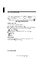
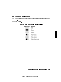
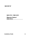
The HP9000 Model 742i
Figure 1-1. Model 742i Front Panel
Features of the 742i
The Model 742i has the following features:
50 Mhz PA-RISC processor delivering 61 MIPs.
Congurable with 8 to 64 MB main memory (see \Memory Upgrades"). For
an HP-UX system, at least 16 MB of main memory is required.
ECC RAM correction.
2 memory module slots.
External Cache: 64 KB instruction cache and 64 KB data cache.
Input/Output:
RS-232-C (2).
AUI
SCSI-II SE
Memory Upgrades
Upgrades or factory-integrated RAM provide 16 MB, 32 MB, and 64 MB
memory congurations. See Appendix A.
1-2
Product Description
FINAL TRIM SIZE : 7.0 in x 8.5 in
1
Built-In Interfaces
For graphics, printing, and LAN communications, the Model 742i provide the
following I/O interfaces:
HP-Parallel Interface.
LAN AUI (15-pin D-subminiature; requires MAU for connection to LAN).
2 Asynchronous RS-232 Interfaces: 9-pin male DTE (PC standard).
SCSI-II Interface: 50-pin high density; single-ended 8-bit, up to 5 MB/sec.
synchronous.
The I/O for the Model 742i is on the front panel, shown on the opposite page.
Physical Dimensions and Power Requirements
Height: 40.6 mm. (2 VMEbus slots).
Width: 233.3 mm. (9.2 in.)
Depth: 160 mm. (6.3 in.)
Weight: .91 kg. (2.0 lb.)
Power:
35 watts @ +5 vdc.
0.12 watts @ +12 vdc.
0.12 watts @ -12 vdc.
Product Description
FINAL TRIM SIZE : 7.0 in x 8.5 in
1-3
1
Operating System
HP-UX 9.01 for the Model 742i the HP VUE interface, and the X Window
System.
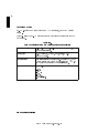
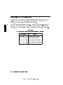
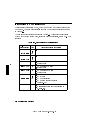
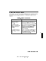
Table 1-1 lists the HP-UX operating system features and languages for the
Model 742i.
Table 1-1.
HP-UX Operating System and Languages for the Model 742i
Operating system:
HP-UX 9.01 or later. HP-UX complies with XOpen, and
POSIX specications.
Languages:
HP-PA Assembly, ANSI/C, C++, Pascal, HP-UX
FORTRAN/9000.
User interface:
Terminal Interface via RS232 only. By using LAN, the X
Window System 11R5 (OSF/Motif 1.2)and HP VUE 3.0
can be used on a suitable X Terminal display).
Network Features:
IEEE 802.3/Ethernet Local Area Network:
S.25.
SNA.
RJE.
TCP-IP.
HP Diskless.
1-4
Product Description
FINAL TRIM SIZE : 7.0 in x 8.5 in
2
Finding Information About Your System
Overview
Your Model 742i uses the standard HP-UX 9.01 operating system, a highly
versatile system for multitasking, running your application programs, and
performing a variety of other tasks.
Chapter Contents
Installing Your Model 742i.
Online Sources of Information.
Finding Information About Your System
FINAL TRIM SIZE : 7.0 in x 8.5 in
2-1
2
2
Installing Your Model 742i
If you have not installed your hardware or started your system, refer to the
Installation Guide for your system before going further.
Basic Information
After you have read the Installation Guide for your system, you may want to
see the following sources for further information:
For a quick reference to commonly-used HP-UX commands, see the
Appendix in Using HP-UX .
At some point, you may want to interact with the Model 742i via the LAN
using HP VUE with an X Window System display. HP VUE is the default
interface for HP-UX. As a simpler window alternative, you can also use the X
Window System. Both are included in HP-UX. For further information, see
the manual Using the X Window System , Using HP-UX , or HP VUE User's
Guide .
The following manuals will also be useful:
If you have not yet installed your HP-UX system, see Installing and
Updating HP-UX 9.0 , which covers HP-UX 9.01.
For administration information, see System Administration Tasks .
For troubleshooting HP-UX, see Solving HP-UX Problems , and Chapter 6
in this manual.
For VME conguration information, see VME Conguration Guide for
HP-UX
2-2
Finding Information About Your System
FINAL TRIM SIZE : 7.0 in x 8.5 in
Online Sources of Information
2
HP-UX is designed so that you can access many sources of information without
leaving your system. Some of these information sources are available through a
shell command line.
Man Pages: The information on HP-UX which is found in HP-UX Reference
is also on line and accessible by clicking on the Toolbox button at the right
of your Front Panel, or by entering on a command line man command , where
command is the name of the HP-UX command you want to get information
on. If you're not sure of the command name you can enter man -k keyword ,
where keyword is a likely topic word to search on. This will result in a
display listing commands having the keyword in their description.
There are also a variety of les on your HP-UX system which contain
version-specic information which will be useful in administering and
conguring cards and devices for your version of HP-UX. Among these are the
following:
Release Notes: This is the online version of the Release Notes which came
with your system. It contains all the late information, undocumented
changes and bug xes for your release of HP-UX. Release Notes is found in
the /etc/newconfig directory, and may be named by its release number,
e.g., 90RelNotes, for HP-UX 9.0.
Terminfo: The directory /usr/lib/terminfo contains subdirectories
containing information about terminal congurations, indexed by the
rst character of the terminal name. For example, to nd conguration
information about the hp98546, you can look in /usr/lib/terminfo/h for a
listing of information les for all the terminal names beginning with \h".
These lenames also constitute all the acceptable arguments for setting the
TERM variable, in case you are using a non-default terminal conguration.
Finding Information About Your System
FINAL TRIM SIZE : 7.0 in x 8.5 in
2-3
2
Newcong: The directory /etc/newconfig contains information and new
versions of HP-UX product conguration les, as well as shell scripts which
may have been customized (localized) on your system. The contents of this
directory will vary depending on which products you have loaded on your
system. In most cases, old versions of these les, in their regular locations in
the le system, are not overwritten by the update process. See the README
le in /etc/newconfig for information on the contents of this directory.
2-4
Finding Information About Your System
FINAL TRIM SIZE : 7.0 in x 8.5 in
3
Logging In and Getting Started
3
Chapter Contents
Before Logging In the First Time.
Turning On Your System.
Interpreting the LED Indicators.
Logging In and Out.
Creating a New User Account.
Setting or Changing a Password.
Getting Help.
Shutting Down Your System.
Logging In and Getting Started
FINAL TRIM SIZE : 7.0 in x 8.5 in
3-1
Before Logging In the First Time
3
If your Model 742i system does not have a hard disk attached, or if it has a le
system disk, and you want it to be a cluster client node (cnode), refer to the
manual Managing Clusters of HP-UX Computers for instructions on setting up
clusters and cnodes.
This chapter reviews some initial procedures and provides information on using
both HP VUE sessions and HP-UX. For more detailed information about using
HP VUE after login, see the HP VUE User's Guide .
When you turn on your Model 742i to complete the installation process, you
will be asked for the following information. If you do not have this information
readily available, simply press 4Return5 after the questions, and you can supply
this information later:
The time zone where your system is located.
The host name for your system; any alphanumeric, single-word name with
eight or fewer characters.
The network address number, also called an IP number, for your system.
This consists of four address elds separated by periods: for example,
255.32.3.10 . You may need to consult with your system administrator for
this information. Or, if your host name and IP number have already been
assigned, you can nd out the host name, after boot, by entering uname -a.
If you know your host name, you can nd out your IP number by entering
nslookup host name , at the system prompt.
If you can't supply this information at boot time, you can congure it into the
system later, after logging in, by entering the command set_parms, as root.
You can then enter the information at the prompts.
3-2
Logging In and Getting Started
FINAL TRIM SIZE : 7.0 in x 8.5 in
Turning On Your System
With all peripheral devices turned o, do the following:
1. Turn on the power to your display. The power indicator LED on the display
unit will show that it is turned on, even if the screen remains dark. Make
sure of the following:
a. The appropriate LAN connection has been made to the Model 742i.
b. Normally, you will use a character terminal connected to the RS232A
port on the Model 742i. If you use a remote graphical display host
connected via LAN, make sure the remote system is congured to host
the Model 742i. See \Displaying Graphics on a Remote X Host", in this
chapter, for the specics of setting this up.
2. Check SCSI connections and turn on the power to any peripheral devices.
3. Turn your Model 742i system on. The LEDs on the front panel will light,
showing that the power is on .
4. You should see a sequence of boot messages. Allow the boot to continue.
5. During the boot process, messages will prompt you for the host name, IP
number, and time zone. If you have this information, enter it as requested.
Otherwise, press 4Return5. You can also enter this information later by typing
set_parms 4Return5 after login.
6. You will be asked if you want to set a root password at this time. If you
choose to do this, see \Selecting a New Password", in this chapter, for
password requirements.
The system will nish the boot sequence, and you will see the \Console
login:" prompt.
Logging In and Getting Started
FINAL TRIM SIZE : 7.0 in x 8.5 in
3-3
3
Displaying Graphics on a Remote X Host
3
With the Model 742i, you can run HP VUE or the X Window System, but you
cannot directly display them. However, you can use a remote computer which
has graphical capability to display the system running on the Model 742i and
interact with it. This is done by setting the DISPLAY environment variable on
the Model 742i. DISPLAY sets the host, display number, and screen number to
which a system sends bitmapped output for clients.
For example, if the Model 742i is called server system , your remote system is
xhost system , and the program running on the Model 742i is called xwijit,
enter the following on your remote X host system to get it to display the Model
742i bits:
xhost +server system
This enables the Model 742i to recognize the
remote X host.
rlogin server system
Log in on the Model 742i.
DISPLAY=xhost system:0.0 On the Model 742i, set the DISPLAY variable so
that it will display on your remote X system.
export DISPLAY
Export the variable
xwijit
Run the program on the Model 742i
For More Information
For detailed information on running HP VUE in a networked environment, see
the HP VUE User's Guide .
3-4
Logging In and Getting Started
FINAL TRIM SIZE : 7.0 in x 8.5 in
Caution
If your system has its own disk and you are running a local
operating system, do not turn o power to your system without
rst shutting down the operating system software according to
the procedure in this chapter, \Shutting Down Your System".
Turning o the power for your stand-alone system without rst
doing the shutdown procedure may result in damage to data on
your disk. Always execute the shut-down process to completion
rst.
If you are running your system as a node in a cluster (without
a le system disk) you can, in any case, shut down your system
by turning o the power after you have properly closed les
and terminated processes. If you have a mounted le system
disk, you must become root and perform the procedure
in \Shutting Down Your System", or have your system
administrator do so. You can run shutdown without being root
by being listed in the le /etc/shutdown.allow. See System
Administration Tasks for details.
Logging In and Getting Started
FINAL TRIM SIZE : 7.0 in x 8.5 in
3-5
3
Interpreting the LED Indicators
There are nine LEDs (\Light Emitting Diodes"), which you can view on the
front. Eight of these are diagnostic, or indicate the normal activity of your
system. The one on the far left indicates power \on".
3
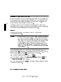
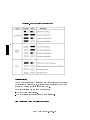
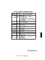
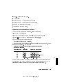
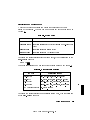
The normal running indications for HP-UX are shown in Table 3-1. The right
four of the eight diagnostic LEDs will blink to reect activity during normal
operation. For LED indications of error conditions during boot, see Table 6-1.
Table 3-1.
LED Diagnostic Display During Normal HP-UX Operation
LED Display
Meaning
Operating system running
Disk access in progress
Network receive in progress
Network transmit in progress
3-6
Logging In and Getting Started
FINAL TRIM SIZE : 7.0 in x 8.5 in
Logging In and Out
Once HP-UX is running on your system, you must log in. The process of
logging in is one of the ways that HP-UX prevents unauthorized persons from
using your system. This is especially important if your system is attached to a
network.
Logging In with HP-UX
If you are not using HP VUE, then a command-line login prompt appears after
boot:
login:
1. Type your login name (or root).
2. Press 4Return5.
If you haven't yet set a password, you will get a a system prompt (\#" for
root, or $ for user), and you can begin using the system.
3. Otherwise, type your password when the system gives the following prompt:
Password:
4. Press 4Return5. The system prompt (\#" or \$") appears and you can use the
system.
Logging Out with HP-UX
If you are not using HP VUE, you can use the lock command to temporarily
leave your system (while leaving processes running). If you want to log out of
your current work session entirely, use the following command:
exit
Logging In and Getting Started
FINAL TRIM SIZE : 7.0 in x 8.5 in
3-7
3
Creating a New User Account
3
If you have access to a system administrator, that person may have already set
up a user account for you. Otherwise, you will need to do the following to set
up a user account so that you can interact with the system as non-root and
not incur the risk of accidentally damaging data.
You usually work in your home directory or \account", and most of your
default les are kept there. As \owner" of this directory and its subdirectories,
you also have control over access to the les in the account.
Using SAM
To create a user account, you will need to use \SAM", the System
Administration Manager.
Caution
In order to use SAM, you must be logged in as root (indicated
by the command prompt \#"). The root account is a separate
login account providing unlimited permissions on your system.
This means that you need to take actions more carefully when
you are root. The root account is only used to do system
administration tasks, and, for security reasons, it should use a
password which is dierent from your everyday user password.
Using HP-UX and System Administration Tasks give you more
details on using SAM.
You can navigate around a SAM screen on a character terminal using the
arrow keys and 4Tab5 to illuminate the selection you want to activate. When the
selection is illuminated, press 4Return5 to activate, or \choose" it.
1. Type usr/bin/sam, as root, followed by 4Return5.
2. At the opening menu, choose Users and Groups-> pressing 4Return5 with
Users and Groups-> illuminated.
NNNNNNNNNNNNNNNNNNNNNNNNNNNNNNNNNNNNNNNNNNNNNNNNNNNNNNNN
NNNNNNNNNNNNNNNNNNNNNNNNNNNNNNNNNNNNNNNNNNNNNNNNNNNNNNNN
3. At the next screen, choose Users . You will see a screen displaying a list of
logins and real names.
NNNNNNNNNNNNNNNNN
3-8
Logging In and Getting Started
FINAL TRIM SIZE : 7.0 in x 8.5 in
4. Go to the Actions menu (use the appropriate function key to get to the
menu bar). Select Add from the Actions pull-down menu. You will see a
form Add a User Account .
NNNNNNNNNNNNNNNNNNNNNNN
NNNNNNNNNNN
NNNNNNNNNNNNNNNNNNNNNNN
NNNNNNNNNNNNNNNNNNNNNNNNNNNNNNNNNNNNNNNNNNNNNNNNNNNNNNNN
5. Fill in your login name, choice of start-up program and environment (if
dierent from the defaults given), and the optional information.
3
At this point you can select X Windows as your login default
environment, if you so desire.
Note
NNNNNNNN
6. Choose OK when you are nished.
7. You will be asked to select a password. (See \Selecting a New Password"
for password requirements. If you wish, you can select a temporary
password and reset it later). Type the password and choose OK (or
press 4Return5). Re-enter the password, as requested, and choose OK . The
re-entered password must match the rst.
8. Choose OK .
NNNNNNNN
NNNNNNNN
NNNNNNNN
9. When the \Task Completed" message appears, choose OK .
NNNNNNNN
10. Press the Exit SAM function key.
NNNNNNNNNNNNNNNNNNNNNNNNNN
11. Type exit 4Return5 to leave SAM.
Logging In and Getting Started
FINAL TRIM SIZE : 7.0 in x 8.5 in
3-9
Setting or Changing a Password
From a command line shell prompt, you can use the passwd command
directly to set or change a password. (You do not have to be root). Enter the
following:
3
passwd
4Return5
You will be prompted for your old password. Then you will be prompted to
enter and re-enter your new password. The re-entered password must match
the rst entry.
See the later section in this chapter, \Selecting a New Password", if you
need help with selecting passwords. Use the same procedure to change an
old password as to add a new password. If you already have one, you will be
prompted appropriately for the old password.
Selecting a New Password
If you have already booted and used your system, you should already have set
dierent passwords for your user account and for root.
However, you will also want to change your password from time to time as a
matter of good security practice. The following gives the general requirements
of setting passwords.
A password must meet four criteria to be valid:
Contain at least six characters.
At least two characters must be alphabetic.
At least one character must be a number (0-9) or a special character (/, ?, !,
or other punctuation mark).
Dier from your previous password by at least three characters.
Your password is case-sensitive, so the password ?Secret is dierent from the
password ?secret. Your password can also be as long as you want, but only
the rst eight characters are checked.
If you are adding many users to your system, see System Administration Tasks
for the details of controlling access to your system.
If you have not yet set your password, you can do so using SAM or a shell
command line.
3-10
Logging In and Getting Started
FINAL TRIM SIZE : 7.0 in x 8.5 in
Shutting Down Your System
If you need to cycle power on a system using a local disk, you will have
to execute the shutdown command rst. You can do this either from the
command line or within SAM.
3
Using the Shutdown Command to Stop Your System
Caution
If your Model 742i uses a local system disk, do not turn o
power to your system without rst shutting down the operating
system software according to the following procedure. Turning
o the power for your system without rst doing the shutdown
procedure may result in damage to data on your disk. Always
execute the shut-down process to completion rst.
1. As root, enter the following command:
shutdown -h
This will give you and any other users on your system a one-minute \grace
period" to save les and terminate processes before the system goes down to
the halted state.
2. You will see a message:
Waiting a grace period of 60 seconds for users to logout.
off the power or press reset during this time.
Do not turn
(You can specify this message and you can determine the \grace period"
that shutdown allows. See shutdown (1M)) and System Administration Tasks
for using various options.
3. At the end of the period, you will see another warning and the following
request for conrmation:
Do you want to continue? ...
4. Respond with y. You will see another message conrming shutdown.
Finally, you will see the following message:
Halted, you may now cycle power.
Logging In and Getting Started
FINAL TRIM SIZE : 7.0 in x 8.5 in
3-11
5. At this time the system no longer responds to keyboard input and you may
turn o the power. Turning the system back on again will initiate the boot
process.
If you want to shutdown and reboot automatically type the following
command:
3
shutdown -r.
If you want to shutdown immediately with no grace period, type the following:
shutdown -h 0
Using SAM to Stop Your System
If you happen to be using SAM, you might also want to use it to shut down
your system.
Caution
Do not turn o power to your system without rst shutting
down the operating system software according to the following
procedure. Turning o the power for your system without rst
doing the shutdown procedure may result in damage to data on
your disk. Always execute the shutdown process to completion
rst.
You can log in as root and shut down your system, using SAM.
1. As root type /usr/bin/sam .
2. Choose Routine Tasks from the opening menu.
NNNNNNNNNNNNNNNNNNNNNNNNNNNNNNNNNNNNNNNNN
3-12
Logging In and Getting Started
FINAL TRIM SIZE : 7.0 in x 8.5 in
3. Choose System Shutdown .
NNNNNNNNNNNNNNNNNNNNNNNNNNNNNNNNNNNNNNNNNNNNNNN
4. You will be given a choice of the following:
a. Halt the System . All currently executing processes except those
essential to the system are terminated. Then the system is halted.
b. Reboot (Restart) the System . The system is shut down and rebooted
automatically.
c. Go to Single User State . The system is put in single-user mode for
administrative purposes such as backup or le system consistency checks.
5. Exit SAM using the appropriate function key.
NNNNNNNNNNNNNNNNNNNNNNNNNNNNNNNNNNNNNNNNNNNNNNN
NNNNNNNNNNNNNNNNNNNNNNNNNNNNNNNNNNNNNNNNNNNNNNNNNNNNNNNNNNNNNNNNNNNNNNNNNNNNNNNNNNN
NNNNNNNNNNNNNNNNNNNNNNNNNNNNNNNNNNNNNNNNNNNNNNNNNNNNNNNNNNNNNNNNNNNNNNN
Using the Command Line
For guidance on entering commands and using the HP-UX le system, tools,
and networking commands, see the manual, Using HP-UX . For more advanced
work with shell programming, see the manual Shells: User's Guide .
Logging In and Getting Started
FINAL TRIM SIZE : 7.0 in x 8.5 in
3-13
3
FINAL TRIM SIZE : 7.0 in x 8.5 in
4
Configuring HP-UX for Printers and Drives
Chapter Contents
Preparing for Installation.
Conguring HP-UX for a Printer.
Finding the Status of Existing SCSI Bus Addresses.
Conguring for a Hard Disk Drive.
Conguring for a Flexible Disk Drive.
Conguring for a CD ROM Drive.
Conguring for a DDS Tape Drive.
Configuring HP-UX for Printers and Drives
FINAL TRIM SIZE : 7.0 in x 8.5 in
4
4-1
Preparing for Installation
If you have external devices attached to your system, you will have to install
(or congure) them on HP-UX. You may also have to do some conguration
for appropriate data interchange with a new printer. This chapter gives you
general guidance for these tasks.
4
In general:
For a list of devices which are supported by the Model 742i, see Chapter 1.
See the Installation Guide for the device you are installing for information
on hardware installation. You can also get installation information from
Installing Peripherals .
Ensure that each new device you install which communicates through the
SCSI protocol has a unique bus address . You can use /etc/ioscan (see
\Finding the Status of Existing SCSI Bus Addresses") to determine this, or
you can use SAM (System Administration Manager). The factory-set SCSI
addresses for the devices in this chapter are as follows:
Hard Disk Drive: 6
Flexible Disk Drive: 0
CD ROM Drive: 2
DDS Drive: 3
This chapter shows you how to use essential SAM (System Administration
Manager) procedures. SAM will determine the status of any of your
connected devices and will perform software installation tasks for you.
If you don't want to use SAM, or it is not on your system, you can also
HP-UX commands directly to accomplish the same tasks. For information on
using manual system administration procedures, see System Administration
Tasks .
4-2
Configuring HP-UX for Printers and Drives
FINAL TRIM SIZE : 7.0 in x 8.5 in
Configuring HP-UX for a Printer
You will need to supply certain items of information needed to identify the
printer you are installing. It will help to have this information available to refer
to during the software installation process:
Printer Interface:
Parallel:
Serial (RS232) Port 1:
4
Serial (RS232) Port 2:
Printer Name (a name the system uses to identify the printer. It can be any
name.):
Printer Model Number (located on a label on the back of the printer):
Procedure:
To install your printer:
1. Log in as root.
2. Run SAM by typing:
/usr/bin/sam
To get help in SAM, pressing the 4f15 key gives you context-sensitive
information for the object at the location of the cursor.
Use the arrow keys and 4Tab5 to move the highlighted areas around the
screen. Press 4Return5 to \choose" an item when illuminated (such as OK ).
NNNNNNNN
3. At the SAM opening screen, choose Printers and Plotters .
NNNNNNNNNNNNNNNNNNNNNNNNNNNNNNNNNNNNNNNNNNNNNNNNNNNNNNNNNNNNNNNNN
4. Choose Printers/Plotters from the next screen.
NNNNNNNNNNNNNNNNNNNNNNNNNNNNNNNNNNNNNNNNNNNNNNNNNNNNN
Configuring HP-UX for Printers and Drives
FINAL TRIM SIZE : 7.0 in x 8.5 in
4-3
If your system doesn't have any printers connected, you will see a message.
Make sure you have a printer connected. Choose OK or press 4Return5.
NNNNNNNN
5. From the Actions menu (on the menu bar at the top of the screen),
choose Add Local Printer/Plotter
NNNNNNNNNNNNNNNNNNNNNNN
NNNNNNNNNNNNNNNNNNNNNNNNNNNNNNNNNNNNNNNNNNNNNNNNNNNNNNNNNNNNNNNNNNNNNNNNNNNNN
6. Choose an appropriate selection on the sub-menu giving options for
Parallel, Serial, HP-IB, etc.
7. A screen will give you information on available parallel or serial interfaces.
8. If you chose Add Serial (RS-232) Printer/Plotter , more than
one serial interface could be listed. The serial interfaces are listed in
ascending order. The lowest-numbered serial interface corresponds to the
lowest-numbered serial connector on your system. Choose the one to which
you have connected your printer.
9. Choose OK
NNNNNNNNNNNNNNNNNNNNNNNNNNNNNNNNNNNNNNNNNNNNNNNNNNNNNNNNNNNNNNNNNNNNNNNNNNNNNNNNNNNNNNNNNNNNNNNNNNNNNNNNNN
4
NNNNNNNN
NNNNNNNNNNNNNNNNNNNNNNNNNNNNNNNNNNNNNNNNNNNNNNNNNNNNNNNNNNNNNNNNNNNNNNNNNNNNN
A display opens for Add Local Printer/Plotter .
10. Choose the box labeled Printer Name and enter your printername for the
new printer (entered in the blank earlier).
11. Choose Printer/Model Interface
NNNNNNNNNNNNNNNNNNNNNNNNNNNNNNNNNNNNNN
NNNNNNNNNNNNNNNNNNNNNNNNNNNNNNNNNNNNNNNNNNNNNNNNNNNNNNNNNNNNNNNNNNNNNNN
12. Scroll down the next screen, using the arrow keys, to nd the Model Name
of your printer.
13. Choose the Model Name (press 4Return5 when illuminated).
14. Choose OK .
NNNNNNNN
15. In the Add Local Printer/Plotter display which reappears, select and
choose the box labeled Make this the system default printer .
NNNNNNNNNNNNNNNNNNNNNNNNNNNNNNNNNNNNNNNNNNNNNNNNNNNNNNNNNNNNNNNNNNNNNNNNNNNNN
NNNNNNNNNNNNNNNNNNNNNNNNNNNNNNNNNNNNNNNNNNNNNNNNNNNNNNNNNNNNNNNNNNNNNNNNNNNNNNNNNNNNNNNNNNNNNNNNNNNNNNNNNNNNN
16. Choose OK .
NNNNNNNN
17. If the print spooler was not previously running, a screen will appear with
the question: Do you want to start the print spooler now? . Choose
Yes or press 4Return5.
NNNNNNNNNNNNNNNNNNNNNNNNNNNNNNNNNNNNNNNNNNNNNNNNNNNNNNNNNNNNNNNNNNNNNNNNNNNNNNNNNNNNNNNNNNNNNNNNNNNNNNNNNNNNNNNNNNNNNNNNNNNNNNNNNN
NNNNNNNNNNN
4-4
Configuring HP-UX for Printers and Drives
FINAL TRIM SIZE : 7.0 in x 8.5 in
18. You will see a conrmation screen asking if your printer is turned on,
connected to your system, and online. Check your printer to ensure that it
is ready, and press 4Return5.
19. You will see the message Task completed . Press 4Return5.
NNNNNNNNNNNNNNNNNNNNNNNNNNNNNNNNNNNNNNNNNNNN
20. Exit the task and press the Exit SAM function key.
NNNNNNNNNNNNNNNNNNNNNNNNNN
21. Type exit 4Return5 to exit root and return to user status.
Refer to System Administration Tasks , for additional SAM information.
4
Testing the Printer Installation
If you made your printer the default system printer, type the following
commands to test it:
cd
4Return5
lp .profile
4Return5
(If your printer (called printername ) isn't the default system printer, enter the
following command to test it:)
lp -dprintername .profile
4Return5
The le named .profile should print out on your new printer.
Configuring HP-UX for Printers and Drives
FINAL TRIM SIZE : 7.0 in x 8.5 in
4-5
Dealing With Printer Problems
4
If you experience problems in printing, check the following:
The power cord for the printer is plugged in.
The printer is turned on.
The printer selection switches are set for online.
Paper is loaded into the printer (and it isn't jammed).
The correct interface has been set up.
The printer cable is connected to the correct interface port on your printer.
The cable is connected to the correct port on your system.
4-6
Configuring HP-UX for Printers and Drives
FINAL TRIM SIZE : 7.0 in x 8.5 in
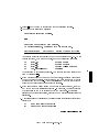
Finding the Status of Existing SCSI Bus Addresses
Before you attach a new SCSI drive, to ensure that the SCSI bus address of
your device is currently unused, you can use SAM, or you can use the ioscan
tool to help determine which devices are currently connected. To determine the
currently connected SCSI bus IDs, enter the following command line:
/etc/ioscan -fb
The result will be a display of information, such as the following:
Class
H/W Path Driver
H/W Status
S/W Status Description
=========================================================================
4
...
disk
2.0.1.2.0 scsi
ok(0x5800101) ok
tape_drive 2.0.1.3.0 scsitape ok(0x1800202) ok
disk
2.0.1.6.0 scsi
ok(0x101)
ok
TOSHIBA CD-ROM
HP
HP35450A
MICROP 1528
...
For example, the SCSI bus address for the \MICROP" disk device is in the
fourth column of its hardware address as \6" (2.0.1.6 .0). If you were
installing another disk, for le system use, it would best be accessed at the
adjacent SCSI bus address in the \scanning" order, \5". SAM would help you
determine where to put it when you did the installation.
Configuring HP-UX for Printers and Drives
FINAL TRIM SIZE : 7.0 in x 8.5 in
4-7
Configuring for a Hard Disk Drive
Hard disk drives can be attached for accommodating HP-UX, local le systems,
and swap space on your Model 742i system.
Software Installation of the Hard Disk Drive Upgrade
4
After all connections have been made (see the Installation Guide for this
device), you'll need to ensure that your operating system is prepared to
exchange data with the device. This section provides instructions for manually
conguring HP-UX to communicate with hard disk drives, in order to use
the disks for mass storage and/or swap space. Note that your HP disk is
pre-formatted.
The factory-set SCSI bus address for the disk drive:
SCSI bus address: 6
This SCSI address assumes usage of the disk as root. Although the
conguration jumpers in the back of the drive are factory-installed and should
not require reconguring, it is possible that the SCSI bus address jumpers
for the disk may be shipped with dierent settings. Therefore, please see the
Installation Guide for the drive for the procedure for resetting jumpers, should
it be necessary.
The following list outlines the software procedures you'll nd in this section for
installing the hard disk drive as a le system disk:
Verify that you have an unused device le with the correct select code and
bus address for your device. (Use SAM or the script in \Finding the Status
of Existing SCSI Bus Addresses").
Use SAM to:
Install a disk on HP-UX.
Build a le system on the disk (done automatically by SAM).
Mount the disk so that you can access it as a le system.
4-8
Configuring HP-UX for Printers and Drives
FINAL TRIM SIZE : 7.0 in x 8.5 in
Note
SAM does not support the following:
Changing the hardware address of a disk drive containing
the root le system.
Changing the hardware address of a disk array.
Changing the hardware address of a disk that is part of
software disk striping.
After all appropriate connections have been made (see the Installation Guide
for this device), you'll need to ensure that your operating system is prepared
to exchange data with the device. This section provides instructions for doing
this.
1. Run SAM by typing:
/usr/bin/sam
Pressing the 4f15 key gives you context-sensitive information for the object
at the location of the cursor.
2. Choose Disks and File Systems (highlight the selection and press
4Return5).
3. Choose CD-ROM, Floppy, and Hard Disks .
NNNNNNNNNNNNNNNNNNNNNNNNNNNNNNNNNNNNNNNNNNNNNNNNNNNNNNNNNNNNNNNNNNNN
NNNNNNNNNNNNNNNNNNNNNNNNNNNNNNNNNNNNNNNNNNNNNNNNNNNNNNNNNNNNNNNNNNNNNNNNNNNNNNNNNNNNNNNNNNNN
4. Choose the line identifying the type of new disk you have connected. In the
\Use" column, it will be designated as \unused".
5. In the next screen, choose the line identifying the model of the new disk.
If the device you have connected does not appear on the list:
a. Check your connections, and make sure that the device is turned on .
b. Choose the button Device Missing , and you will be given the
following options:
i. Have SAM rescan the system for the device. If you have connected
the device after starting SAM, you should choose Yes . Otherwise,
choose No .
NNNNNNNNNNNNNNNNNNNNNNNNNNNNNNNNNNNNNNNNNNNN
NNNNNNNNNNN
NNNNNNNN
Configuring HP-UX for Printers and Drives
FINAL TRIM SIZE : 7.0 in x 8.5 in
4-9
4
4
ii. Respond to the conrmation screen regarding whether the device is
connected and powered up.
iii. Respond to the conrmation screen regarding whether additional
device drivers are needed. (Unless the kernel has, for some reason,
had drivers removed, the drivers needed for a hard disk should
currently be in the kernel.)
iv. You will be given an information screen suggesting things to try if
the device still cannot be found. If this is the case, you will need to
consult Installing Peripherals .
6. After you choose the device, you will see a form giving three tasks:
a. Select a Disk to Add . (You have already done this).
NNNNNNNNNNNNNNNNNNNNNNNNNNNNNNNNNNNNNNNNNNNNNNNNNNNNNNNNNNNNNN
b. Set Disk Usage and Options .
NNNNNNNNNNNNNNNNNNNNNNNNNNNNNNNNNNNNNNNNNNNNNNNNNNNNNNNNNNNNNNNNNNNNNNNNNNNNNNNN
c. Modify Defaults... . (This task is optional).
NNNNNNNNNNNNNNNNNNNNNNNNNNNNNNNNNNNNNNNNNNNNNNNNNNNNNNNN
NNNNNNNNNNNNNNNNNNNNNNNNNNNNNNNNNNNNNNNNNNNNNNNNNNNNNNNNNNNNNNNNNNNNNNNNNNNNNNNN
Choose Set Disk Usage and Options .
7. On the form which appears, select how you want to use the disk (\File
System", or other usage).
8. Choose OK when you have nished with this form.
NNNNNNNN
9. A \Messages" Box appears, reporting the progress of the task. When the
task is nished, choose 4OK5.
10. Exit SAM. (SAM copies your original /etc/checklist to
/etc/checklist.old).
Testing Your Installation
A simple test to make certain that the drive has been installed correctly
(whether it is mounted or not) is to execute the command diskinfo (using the
appropriate character device le name as the argument). For example:
diskinfo /dev/rdsk/c201d5s0
If the disk is installed correctly, diskinfo will display a listing of information
about it, such as the following:
4-10
Configuring HP-UX for Printers and Drives
FINAL TRIM SIZE : 7.0 in x 8.5 in
SCSI describe of /dev/rdsk/c201d5s0
vendor: Quantum
product id: XXXXXXX
type: direct access
size: 200000 Kbytes
bytes per sector: 512
After mounting a new disk on a directory, an ll listing of the directory should
give you at least one le or directory entry. For example:
total 1024
drwxr-xr-x
2 root
root
8192 Aug 31 15:24 lost+found
Configuring HP-UX for Printers and Drives
FINAL TRIM SIZE : 7.0 in x 8.5 in
4-11
4
Configuring for a Flexible Disk Drive
Note the exible disk drive jumpers are pre-congured correctly at the factory.
It should not be necessary to change jumper settings.
The factory-set SCSI bus address for the drive:
SCSI bus address: 0
4
As it is possible that the SCSI bus setting for the drive may be shipped
dierently, please check the setting before installation. See the Installation
Guide for the device for the procedure for resetting the device, should it be
necessary.
After hardware connections have been made, you'll need to ensure that your
operating system is prepared to exchange data with the device. This section
provides instructions for doing this.
1. If you wish to initialize a new disk, make sure you have the disk loaded in
the drive.
2. Run SAM by typing:
/usr/bin/sam
To get help in SAM, pressing the 4f15 key gives you context-sensitive
information for the object at the location of the cursor.
3. Choose Disks and File Systems (highlight and choose 4OK5 or press
4Return5).
4. Choose CD-ROM, Floppy, and Hard Disks .
NNNNNNNNNNNNNNNNNNNNNNNNNNNNNNNNNNNNNNNNNNNNNNNNNNNNNNNNNNNNNNNNNNNN
NNNNNNNNNNNNNNNNNNNNNNNNNNNNNNNNNNNNNNNNNNNNNNNNNNNNNNNNNNNNNNNNNNNNNNNNNNNNNNNNNNNNNNNNNNNN
5. From the Actions menu, select Add a Floppy Disk Drive... . You will
see a list of unused disks, including the new one you have connected.
6. Choose the line identifying the model of the new disk.
NNNNNNNNNNNNNNNNNNNNNNN
NNNNNNNNNNNNNNNNNNNNNNNNNNNNNNNNNNNNNNNNNNNNNNNNNNNNNNNNNNNNNNNNNNNNNNNNNNNNNNNN
If the device you have connected does not appear on the list:
a. Check your hardware connections, and make sure that the device is
turned on .
b. Choose the button Device Missing , and you will be given the
following options:
NNNNNNNNNNNNNNNNNNNNNNNNNNNNNNNNNNNNNNNNNNNN
4-12
Configuring HP-UX for Printers and Drives
FINAL TRIM SIZE : 7.0 in x 8.5 in
i. Have SAM rescan the system for the device. If you have connected
the device after starting SAM, you should choose Yes . Otherwise,
choose No .
NNNNNNNNNNN
NNNNNNNN
ii. Respond to the conrmation screen regarding whether the device is
connected and powered up.
iii. Respond to the conrmation screen regarding whether additional
device drivers are needed.
iv. You will be given an information screen suggesting things to try if
the device still cannot be found.
7. After you highlight the device, note that the Initialize disk button is
toggled on (the default). Choose this button to turn it o if you do not
wish to initialize a disk (or if the disk is preformatted).
8. Choose OK when you have nished with this form.
NNNNNNNNNNNNNNNNNNNNNNNNNNNNNNNNNNNNNNNNNNNNNNN
NNNNNNNN
9. A \Messages" Box appears, reporting the progress of the task. When the
task is nished, choose 4OK5.
10. Exit SAM. (SAM copies your original /etc/checklist to
/etc/checklist.old).
Testing Your Installation
A simple test to make certain that everything has been installed correctly is to
execute the command diskinfo.
1. Make sure a exible disk is inserted in the drive (otherwise, a core dump
may result).
2. Type the following, using the appropriate device le name as the argument.
For example:
diskinfo /dev/rfloppy/c201d0s0
If the disk is installed correctly, diskinfo will display a listing of
information about it, such as the following:
/dev/rfloppy/c201d0s0
SCSI describe of 0.rdsk:
Configuring HP-UX for Printers and Drives
FINAL TRIM SIZE : 7.0 in x 8.5 in
4-13
4
vendor:
product id:
type:
size:
bytes per sector:
TEAC
XXXXXXX
direct access
1400000 bytes
NNN
If you wish to test the installation of your exible disk drive without a disk
installed, use the ioscan command.
Archiving Files to a Flexible Disk
4
Data can be stored on exible disk media in a variety of formats. The capacity
of these devices is generally too small to hold useful HP-UX le systems.
Instead, DOS or LIF le systems are commonly used. Data can also be stored
in an archive-utility format. For example, tar and cpio are commonly used to
share data with other HP-UX systems.
See the man pages or HP-UX Reference references dosif (4) and lif (4) for
detailed descriptions of the le systems. For information on tar and cpio, see
tar (1) and cpio .
To save les archivally to a exible disk using tar, use a formatted disk and
enter the following command line, where pathname is the directory where the
les reside:
tar -cvf /dev/rfloppy/c201d0s0 pathname
Retrieving Files from a Flexible Disk
To list les stored in a tar archive on a exible disk, without transferring them
to your hard disk, use the following command line:
tar -tvf /dev/rfloppy/c201d0s0
This lists all the les on the exible disk.
To transfer or restore les from a exible disk to your hard disk drive, do the
following:
1. Load the source disk into the exible disk drive.
2. Using cd, make sure you are in in directory you want the les to reside in.
4-14
Configuring HP-UX for Printers and Drives
FINAL TRIM SIZE : 7.0 in x 8.5 in
3. Enter the following command line to restore pathname on the disk to your
current directory:
tar -xvf /dev/rfloppy/c201d0s0 pathname
Mounting a New Flexible Disk
If you want HP-UX to be able to address a newly-inserted exible disk as a
small le system, you will need to mount it. Execute the following to mount
the new disk. For example, using \/flex" as the mount directory:
mount /dev/floppy/c201d0s0 /flex
See the next section for information on mounting and unmounting a disk used
as a le system.
Configuring HP-UX for Printers and Drives
FINAL TRIM SIZE : 7.0 in x 8.5 in
4-15
4
Removing and Inserting a File-System Flexible Disk
Caution
4
If you wish to use the disk as a mounted le system, you must
mount it every time you insert it into the drive, and you must
unmount the disk before you eject it from the drive.
You will need to do the following:
Before you remove a disk:
1. Temporarily unmount the le system for the disk by executing the
following. For example, if the disk is designated by the block device le
/dev/floppy/c201d0s0:
umount /dev/floppy/c201d0s0
2. Remove the disk.
After you insert a disk:
1. Mount the disk le system so that HP-UX will recognize it. If, for
example, you are mounting the disk in a drive designated by the device
le /dev/floppy/c201d0s0 under a pre-existing directory /flex, execute
the following:
mount /dev/floppy/c201d0s0 /flex
(Note that the directory /flex, in the example, must be given an absolute
path name).
In this example, the mount command announces to the system that a
removable le system is to be attached at the directory /flex.
2. Now you can access the exible disk as you would any other disk.
4-16
Configuring HP-UX for Printers and Drives
FINAL TRIM SIZE : 7.0 in x 8.5 in
Configuring for a CD ROM Drive
You can use a CD ROM (\Compact Disc Read-Only Memory") drive to
accommodate read-only use of a wide variety of software, including HP-UX
system updates.
After hardware connections have been made (see the Installation Guide for
this device), you'll need to ensure that your operating system is prepared
to exchange data with the device. This section provides instructions for
conguring HP-UX to communicate with the CD ROM drive.
Note
The CD ROM drive cannot be locally-mounted on a diskless
node (cnode), although its driver must be congured into each
cluster node's kernel.
This section deals with the following topics:
Installing the CD ROM with SAM.
Testing the installation.
Mounting the new CD ROM.
Removing and inserting a disc.
The factory-set SCSI address for this device:
SCSI bus address: 2
As it is possible that the CD ROM drive may be shipped with a dierent SCSI
bus setting, please see the Installation Guide for the device for guidance on
resetting it, if necessary.
Inserting the disc in your CD ROM drive.
Note that a rigid plastic caddy holds and protects the disc. Before inserting
the disc, make sure you have the disc installed in the appropriate disc caddy.
When inserted into the disc port, data is read from the disc through a shutter
in the caddy. When you eject the caddy, the shutter closes to protect the disc's
data surface.
The disc caddy for an HP drive is not interchangeable with the HP C1707A
CD ROM Drive disc caddy. However, you can remove the disc from one caddy
Configuring HP-UX for Printers and Drives
FINAL TRIM SIZE : 7.0 in x 8.5 in
4-17
4
and use the other, if necessary, in order to t the appropriate drive. Disc
caddies are available from Hewlett-Packard.
Do not open the disc caddy shutter manually. Opening
the shutter will expose the disc's data surface to dust and
damage. If the data surface gets too much dust or damage,
its readability by the CD ROM drive's laser read head will be
reduced.
Caution
Installing the CD ROM Drive with SAM
4
It is a good idea to make a note of your CD ROM drive model and its
hardware address (select code and bus address), before you do the software
installation.
CD ROM Model:
Bus Address:
Configuring the Drive on HP-UX:
1. Log on as root.
2. Run SAM by entering the following:
$ /usr/bin/sam
3. Choose Disks and File Systems-> .
NNNNNNNNNNNNNNNNNNNNNNNNNNNNNNNNNNNNNNNNNNNNNNNNNNNNNNNNNNNNNNNNNNNNNNNNNN
4. Choose CD-ROM, Floppy, and Hard Disks .
NNNNNNNNNNNNNNNNNNNNNNNNNNNNNNNNNNNNNNNNNNNNNNNNNNNNNNNNNNNNNNNNNNNNNNNNNNNNNNNNNNNNNNNNNNNN
5. From the Actions menubar in the \Disk and File System Manager"
screen, highlight and choose Add a Hard Disk Drive...
NNNNNNNNNNNNNNNNNNNNNNN
NNNNNNNNNNNNNNNNNNNNNNNNNNNNNNNNNNNNNNNNNNNNNNNNNNNNNNNNNNNNNNNNNNNNNNNNNN
6. Within the \Add a Hard Disk Drive" screen, choose
Select disk to add .
NNNNNNNNNNNNNNNNNNNNNNNNNNNNNNNNNNNNNNNNNNNNNNNNNNNNNNNN
7. Within the \Select a Disk to Add" screen, highlight the line identifying the
new drive you have just connected. It will be described as, for example,
4-18
Configuring HP-UX for Printers and Drives
FINAL TRIM SIZE : 7.0 in x 8.5 in
\CD ROM-SCSI", followed by its model number and bus address. Choose
OK or press 4Return5.
NNNNNNNN
If the device you have connected does not appear on the list:
a. Check your hardware connections, and make sure that the device is
turned on and that there is a disc in it.
b. Choose the button Device Missing , and you will be given the
following options:
i. Have SAM rescan the system for the device. If you have connected
the device after starting SAM, you should choose Yes . Otherwise,
choose No .
NNNNNNNNNNNNNNNNNNNNNNNNNNNNNNNNNNNNNNNNNNNN
NNNNNNNNNNN
NNNNNNNN
ii. Respond to the conrmation screen regarding whether the device is
connected and powered up.
iii. Respond to the conrmation screen regarding whether additional
device drivers are needed.
iv. You will be given an information screen suggesting things to try if
the device still cannot be found. If this is the case, you will need to
consult Installing Peripherals .
8. From the Actions menu, select Add a Hard Disk Drive . You will see a
form giving three tasks:
a. Select a Disk to Add . (Make sure the correct device is displayed
and highlighted).
b. If you need to add drivers to the kernel, SAM will prompt you for
doing so and will ask whether you wish to recreate the kernel now or
later. Make this selection by pressing 4Return5 when your selection is
highlighted. Then the selection is designated by an asterisk (*) in its
blank. Choose OK to activate that selection.
NNNNNNNNNNNNNNNNNNNNNNN
NNNNNNNNNNNNNNNNNNNNNNNNNNNNNNNNNNNNNNNNNNNNNNNNNNNNNNNNNNNNNNNNN
NNNNNNNNNNNNNNNNNNNNNNNNNNNNNNNNNNNNNNNNNNNNNNNNNNNNNNNNNNNNNN
NNNNNNNN
c. Set Disk Usage and Options . (File system usage is already set for a
CD ROM.)
d. Modify Defaults... . (This task is optional). You may want to
change certain options, such as when to mount the disk and how its
access permissions are set. If so, within the \Add a Hard Disk Drive"
NNNNNNNNNNNNNNNNNNNNNNNNNNNNNNNNNNNNNNNNNNNNNNNNNNNNNNNNNNNNNNNNNNNNNNNNNNNNNNNN
NNNNNNNNNNNNNNNNNNNNNNNNNNNNNNNNNNNNNNNNNNNNNNNNNNNNNNNN
Configuring HP-UX for Printers and Drives
FINAL TRIM SIZE : 7.0 in x 8.5 in
4-19
4
NNNNNNNNNNNNNNNNNNNNNNNNNNNNNNNNNNNNNNNNNNNNNNN
screen, highlight and activate Modify Defaults . Then, within the
dialog box, turn on the checkboxes that apply.
9. Choose OK when you have nished with this form.
NNNNNNNN
10. A \Messages" Box appears, reporting the progress of the task. When the
task is nished, choose 4OK5.
11. Exit SAM by returning to opening screen and activating 4Exit SAM5.
Testing Your Installation
4
A simple test to make certain that everything has been installed correctly is to
execute the command diskinfo.
1. First make sure a CD ROM is inserted in the drive.
2. Then, type the following (using the appropriate device le name as the
argument). For example:
diskinfo /dev/rdsk/c201d2s0
If the disk is installed correctly, diskinfo will display a listing of
information about it, such as the following:
c201d2s0
SCSI describe of /dev/rdsk/c201d2s0
vendor: TOSHIBA
product id: CD-ROM DRIVE:XM
type: CD-ROM
size: nnnnnn Kbytes
bytes per sector: nnn
Mounting the New CD ROM Drive
SAM will mount the disc for you when you install the drive. You can then
mount it and unmount it manually, using the mount and umount commands, as
with a exible disk.
If you have not already had SAM do so, in order for your system to boot with
the new CD ROM mounted, you will need to edit your /etc/checklist. Add
the following line to the /etc/checklist le:
4-20
Configuring HP-UX for Printers and Drives
FINAL TRIM SIZE : 7.0 in x 8.5 in
/dev/dsk/c201d2s0 /cdrom cdfs ro 0 0 # CD ROM
If you have only made this change to your system, executing mount -a will
mount the new disk automatically, and it will stay mounted until you reboot
your system. (Note that using the -a option mounts all unmounted devices in
/etc/checklist.)
After mounting a new disk on a directory, an ll listing of the directory should
give you at least one le or directory entry. For example:
total 1024
drwxr-xr-x
2 root
root
8192 Aug 31 15:24 lename
See the next section for information on unmounting the disc before you remove
it.
Removing and Inserting a Disc
You must mount a CD ROM disc every time you insert it into the drive, and
you must unmount the disc before the system will allow you to eject it from
the drive.
Note
The eject button on the CD ROM drive is disabled while the
device is mounted or in use.
Configuring HP-UX for Printers and Drives
FINAL TRIM SIZE : 7.0 in x 8.5 in
4-21
4
Before you remove a disc:
1. For example, if the disc is designated by the block device le
/dev/dsk/c201d2s0, temporarily unmount the disk's le system by
executing the following:
umount /dev/dsk/c201d2s0
4
2. Press the eject button to remove the disk
After you insert a disk:
1. Mount the CD ROM le system so that HP-UX will recognize it. If,
for example, you are mounting the CD ROM designated by the device
lename /dev/dsk/c201d2s0, create a directory /cdrom (if it doesn't exist
already) and execute the following:
mount /dev/dsk/c201d2s0 /cdrom
(Note that the directory /cdrom, in the example, must be given an
absolute path name).
In this example, the mount command announces to the system that a
removable le system is to be attached at the directory /cdrom. This
directory becomes the name of the root of the newly-mounted le system.
2. Now you can access the CD ROM as you would any other disk, except
that you cannot write to it.
3. A ashing busy light indicates normal activity with the system.
For More Information
For more information on the mount, umount, and reboot commands, please
see the appropriate entries in HP-UX Reference . You can also use your
online command help system by typing man, followed by the name of the
command, and 4Return5.
Information on the installation of external peripheral devices can be found in
Installing Peripherals .
4-22
Configuring HP-UX for Printers and Drives
FINAL TRIM SIZE : 7.0 in x 8.5 in
Configuring for a DDS Tape Drive
This section contains instructions for conguring a new DDS drive on HP-UX.
The DDS (\Digital Data Storage") Tape Drive is a sequential-access,
read-write device using removable DDS cassettes. Although DDS drives
are similar to DAT players in the audio industry, the cassettes are not
interchangeable. There are two major dierences:
1. Audio cassette tapes transfer data in streaming mode. That is, they are
left in motion for periods of minutes. Tapes used for data are continually
starting, stopping and repositioning, which is stressful to the tape. DDS
tapes are made rugged enough to stand this kind of treatment. Audio tapes
are not expected to perform this well, and as a result fail very quickly in a
data environment.
2. DDS cassettes have a much tighter case dimension specication than DAT
cassettes. As a result, DAT cassettes can get stuck in a DDS drive, requiring
the drive to be disassembled. For this reason, only Hewlett-Packard
supported or properly certied DDS tape cartridges should be used. Use of
DAT tapes intended for audio use could void your warranty.
Caution
Do not attempt to extricate a DAT cassette which is stuck
in a DDS drive. You may damage the drive. Have the drive
disassembled by someone qualied to do so.
Configuring HP-UX for Printers and Drives
FINAL TRIM SIZE : 7.0 in x 8.5 in
4-23
4
4
The steps for adding a DDS tape drive to your system are:
1. Make sure that the necessary device drivers are congured into the kernel.
SAM will make this test.
2. Shut you system down and turn o the power.
3. Choose a SCSI bus address for the new tape drive that does not match the
bus address for any other SCSI device.
4. Make all necessary hardware connections for the device.
5. Turn the new tape drive on .
6. Turn your system on .
7. Run SAM to create the device les for the new tape drive.
The factory-set SCSI address for the DDS drive:
SCSI bus address: 3
As it is possible that the SCSI bus address jumpers for a drive may be shipped
with dierent settings, please check the settings before installing the device.
See the Installation Guide for the device for information on resetting it, should
it be necessary.
Configuring the Drive on HP-UX
NNNNNNNNNNNNNNNNNNNNNNNNNNNNNNNNNNNNNNNNNNNNNNNNNNNNNNNNNNNNNN
The SAM Kernel Configuration procedure will conrm which drivers are
active for your tape devices and will congure them as needed, for connected
devices. Reconguring the kernel will involve rebooting your system.
4-24
Configuring HP-UX for Printers and Drives
FINAL TRIM SIZE : 7.0 in x 8.5 in
Before you begin:
First make a note of the tape drive model and its hardware address (SCSI bus
address) so that you will be able to identify it later.
DDS Drive Model:
Bus Address:
1. Log on as root.
2. Run SAM by entering the following:
4
$ /usr/bin/sam
To get help in SAM, pressing the 4f15 key gives you context-sensitive
information for the object at the location of the cursor.
3. Highlight and select Peripheral Devices ->
NNNNNNNNNNNNNNNNNNNNNNNNNNNNNNNNNNNNNNNNNNNNNNNNNNNNNNNNNNNNNNNNN
4. At the next screen highlight and select Tape Drives ->
NNNNNNNNNNNNNNNNNNNNNNNNNNNNNNNNNNNNNNNNNNNN
5. The Tape Drive Manager screen lists what tape devices are connected,
including your new device. Highlight that device.
6. From the Actions menu, choose Add... . A message screen gives you the
hardware steps for adding the tape drive. Choose OK or press 4Return5.
NNNNNNNNNNNNNNNNNNNNNNNNNNNNNNNNNNNNNNNNNNNNNNNNNNNNNNNN
NNNNNNNNNNNNNNNNNNNNNNN
NNNNNNNNNNNNNNNNNNNN
NNNNNNNN
7. A conrmation screen indicates whether any related device drivers needed
to be added to the kernel. Choose Yes or press 4Return5.
NNNNNNNNNNN
8. If you needed to add a device driver, you will also need to create a new
kernel and (eventually) reboot the system. Select from the menu on
the Create a New Kernel screen whether you want to create the new
kernel now, later, or cancel the proposed modications. (Make sure your
choice has an asterisk placed by it, by pressing Return while that line is
highlighted.) Choose OK to conrm your choice of action.
NNNNNNNNNNNNNNNNNNNNNNNNNNNNNNNNNNNNNNNNNNNNNNNNNNNNNNNNNNN
NNNNNNNNNNNNNNNNNNNN
NNNNNNNN
9. You will next be given a choice of whether to install the new kernel now
or later. If you move the kernel into place now, the system will also
reboot. If you choose to do it later, you can then move the new kernel,
Configuring HP-UX for Printers and Drives
FINAL TRIM SIZE : 7.0 in x 8.5 in
4-25
/etc/conf/dfile.SAM to /hp-ux and reboot. You should also move
/etc/conf/dfile.SAM to /etc/conf/dfile at the same time.
If you reboot, the old kernel will be backed up as /SYSBCKUP.
10. Exit SAM, if you have not already done so.
Note
4
If you are modifying a cluster client's kernel, its kernel is not
backed up, since /SYSBCKUP is used exclusively for the cluster
server's kernel.
Your system is now running the added driver for SCSI DDS tape drive. You
are ready to use the drive to load a tape into your system.
Testing Your Installation
Note that a write-protect tab on the cassette allows you to protect data from
being over-written. You will need to make sure that the tab is moved to the
\writable" position in order for it to serve as a back up medium.
A simple test to make certain that everything has been installed satisfactorily
is to load a tape in the drive, wait for the \busy" light to stop blinking, and
execute the ioscan command:
/etc/ioscan
The LED on the drive should icker briey. If the command completes
successfully, a listing of your devices, including the tape hardware address,
name and status will be displayed, indicating that it is installed correctly. Note
that the command may fail with a busy error if the command is executed
before the tape has completed loading.
4-26
Configuring HP-UX for Printers and Drives
FINAL TRIM SIZE : 7.0 in x 8.5 in
DDS Tape Drive LED Indicators
Two LED indicators on the drive's front panel indicate several operational and
test states. The following tables show the LED combinations and explains
what they indicate.
DDS Tape Drive LED Symbols Used in Table 4-1
4
Configuring HP-UX for Printers and Drives
FINAL TRIM SIZE : 7.0 in x 8.5 in
4-27
Table 4-1. DDS Tape Drive LED State Codes
4
Caution Indicator
The DDS drive continually monitors the number of errors it has to correct
when reading or writing a tape. This information is presented to the user
through the Caution Indicator (see above chart).
A caution indication has two common meanings:
The tape heads need cleaning.
The tape itself is approaching the end of its useful life.
4-28
Configuring HP-UX for Printers and Drives
FINAL TRIM SIZE : 7.0 in x 8.5 in
Maximum Usage of DDS Cassettes
Under optimal environmental conditions (50% relative humidity, 22 C),
Hewlett-Packard DDS cassettes are currently specied to 2000 passes over
any part of the tape. In operational terms, this can be translated into
approximately 200 to 300 backup operations. This takes into account that,
during a backup, an area of tape may have several passes because streaming
cannot be maintained, or because the backup software requires that certain
areas of the tape are accessed frequently.
Under certain conditions, the recommended number of backup operations needs
to be reduced. These conditions are as follows:
Sustained use at low humidity.
Backup software requiring certain areas of the tape being accessed frequently.
As a guideline, HP recommends that the number of backup operations should
be limited to 100 per cassette in extreme cases of the above conditions.
In Case of Difficulty
If you experience any problems with the operation of the new drive, contact
your HP service representative for assistance.
Configuring HP-UX for Printers and Drives
FINAL TRIM SIZE : 7.0 in x 8.5 in
4-29
4
FINAL TRIM SIZE : 7.0 in x 8.5 in
Backing Up, Restoring, and Updating Your
5
Software
Chapter Contents
Backing Up Your System and Software.
Restoring Individual Files.
Restoring Your Operating System Using the Recovery Tape.
5
Backing Up, Restoring, and Updating Your Software
FINAL TRIM SIZE : 7.0 in x 8.5 in
5-1
Backing Up Your System and Software
5
The most important part of your system is the data you have accumulated. It
is also especially important to protect your system from corruption. You can
protect your data and system from loss, using the general procedures given in
this chapter. (For detailed procedures, see Installing and Updating HP-UX 9.0
and System Administration Tasks .)
Make sure you create and maintain a backup HP-UX kernel (/SYSBCKUP)
on your disk from which you can boot in an emergency. A /SYSBCKUP is
automatically created by SAM whenever you recongure and reboot a new
kernel from your system console.
To build your recovery system, you can use the following devices:
Cartridge tape drives
DDS-Format (\DAT") drives
Magneto-optical disk drives
Other hard disk drives
Back up your le system.
Restore your le system, if needed.
Creating a Recovery System
A \recovery system" is a special tape containing a subset of the HP-UX
operating system. In the event of an operating system failure that prevents you
from booting or logging into HP-UX, you can boot from the recovery system
tape and use the tools on the tape to repair the le system on your disk. A
recovery system is created by using commands rather than by using SAM.
You can also restore your system from a system CD ROM that you can
purchase from your HP sales representative.
You should make a recovery tape using mkrs at the following times:
Immediately after you set up the Model 742i.
Each time you update your operating system or make a change in your disk
swap conguration.
To do this, you will need a tape drive (cartridge or DDS-format) and one or
more tapes.
5-2
Backing Up, Restoring, and Updating Your Software
FINAL TRIM SIZE : 7.0 in x 8.5 in
Using mkrs to Create a Recovery System
The mkrs command constructs a recovery system on removable media (or a
formatted hard disk drive). If a system later becomes unbootable due to a
corrupt root disk, then you can boot your system from the recovery tape. Once
booted on the recovery system, you can then use the tools it provides to repair
the corrupt root disk.
Some Options for mkrs
Note
The -s option is necessary for building Series 700 DDS-format
tape recovery systems.
If enough free disk space is available in /usr/tmp (typically 10-20Mb), the -q
option can be used to make mkrs create an image of the recovery system in this
directory before copying it to the recovery media. This option generally saves
a great deal of time due to reduced seeking on non-random-access recovery
media (cartridge tape and DDS-format). Note: for DDS-format tape recovery
systems, the -q option is assumed.
When creating a DDS-format recovery system for a small memory system
(8Mb), the -s option should be used to specify that a smaller set of les be
placed on the recovery system.
See mkrs 1M for more options with mkrs.
Source Device Files
By default, mkrs uses the following device les:
/dev/update.src
/dev/rct/c0
/dev/rct
If none of the above defaults exist on the system, one of these device les must
be created or the -f option must be used to specify the device le to be used.
The recovery device le can be either a block or a character device le.
Backing Up, Restoring, and Updating Your Software
FINAL TRIM SIZE : 7.0 in x 8.5 in
5-3
5
Root Device Files
mkrs, by default, uses the following device les for the root device:
/dev/dsk/0s0
/dev/root
/dev/hd
If none of the above defaults exist on the system, one of these device les must
be created or the -r option must be used to specify the device le to be used.
The root device le must be a block device le.
If You Have a Problem
5
An error message results if:
None of the default device les for the recovery device exist and the -f option
is not used to specify a recovery device le.
None of the default device les for the root device exist and the -r option is
not used to specify a root device le.
The machine type cannot be determined and the -m option is not used to
specify the machine type.
Backing Up Your File Systems
Preparation:
The following procedure sets up a scheduled backup:
1. If your system is more than six months old, you have non-HP supported
software, or you have never done a backup before, see System Administration
Tasks or Installing and Updating HP-UX 9.0 before proceeding. Otherwise,
SAM will provide interactive guidance. To use SAM, do the following:
2. Log in as root.
3. Type /usr/bin/sam.
4. Choose Backup and Recovery from the opening menu.
5. Choose Backup Devices (to determine what backup devices are connected)
or Automated Backups .
NNNNNNNNNNNNNNNNNNNNNNNNNNNNNNNNNNNNNNNNNNNNNNNNNNNNNNNNNNN
NNNNNNNNNNNNNNNNNNNNNNNNNNNNNNNNNNNNNNNNNNNN
NNNNNNNNNNNNNNNNNNNNNNNNNNNNNNNNNNNNNNNNNNNNNNNNNNNNN
5-4
Backing Up, Restoring, and Updating Your Software
FINAL TRIM SIZE : 7.0 in x 8.5 in
a. If you opened Backup Devices , and no devices are shown, make sure
the device is connected and the tape is inserted.
NNNNNNNNNNNNNNNNNNNNNNNNNNNNNNNNNNNNNNNNNNNN
Note
If you have to connect a device during this process, choose
Refresh from the Options menu.
NNNNNNNNNNNNNNNNNNNNNNN
NNNNNNNNNNNNNNNNNNNNNNN
b. Choose the entry for the desired device.
c. Choose Add an Automated Backup from the Actions menu.
NNNNNNNNNNNNNNNNNNNNNNN
NNNNNNNNNNNNNNNNNNNNNNNNNNNNNNNNNNNNNNNNNNNNNNNNNNNNNNNNNNNNNNNNNNNNNNN
1. If you go directly to Automated Backups , you can select your local or
remote backup device from Actions
Add an Automated Backup (Local
or Remote)
Specify Backup Device . A form will display any existing
backup devices.
2. Before initiating the backup, verify that your tape is not write-protected by
checking that the write-protect device is in \writable" position.
3. Load a tape into the tape drive. Depending on what tape drive you are
using, you may see activity lights ashing while the tape is loading. You can
proceed when one light remains on, indicating that the drive is ready to
accept data.
4. From the Add an Automated Backup screen, you can select the options
which will bring up additional forms for specifying the following required
items:
a. Select Backup Device (if you have not already specied it).
b. Select Backup Scope : what lesets to include or exclude. The default
is to backup the entire system.
c. Select Backup Time : time, day, date. You can also set whether you
want a full or incremental backup, for each time specication.
NNNNNNNNNNNNNNNNNNNNNNNNNNNNNNNNNNNNNNNNNNNNNNNNNNNNN
NNNNNNNNNNNNNNNNNNNNNNN
!
!
NNNNNNNNNNNNNNNNNNNNNNNNNNNNNNNNNNNNNNNNNNNNNNNNNNNNNNNNNNNNNNNNNNNNNNN
NNNNNNNNNNNNNNNNNNNNNNNNNNNNNNNNNNNNNNNNNNNNNNNNNNNNNNNNNNNNNNNNN
NNNNNNNNNNNNNNNNNNNNNNNNNNNNNNNNNNNNNNNNNNNNNNNNNNNNNNNNNNNNNNNNNNNNNNN
NNNNNNNNNNNNNNNNNNNNNNNNNNNNNNNNNNNNNNNNNNNNNNNNNNNNNNNNNNNNNN
NNNNNNNNNNNNNNNNNNNNNNNNNNNNNNNNNNNNNNNNNNNNNNNNNNNNNNNNNNN
NNNNNNNNNNNNNNNNNNNNNNNNNNNNNNNNNNNNNNNNNNNNNNNNNNNNNNNN
Backing Up, Restoring, and Updating Your Software
FINAL TRIM SIZE : 7.0 in x 8.5 in
5-5
5
5. Additional Parameters (optional) allows you to specify the following:
NNNNNNNNNNNNNNNNNNNNNNNNNNNNNNNNNNNNNNNNNNNNNNNNNNNNNNNNNNNNNNNNN
a. If you want your backups to cross NFS mount points.
b. If you want the tape (cartridge or autochanger) rewound.
c. If you want an index log to be created for each backup. (Results can be
mailed to a specied user).
6. After the minimum required forms are lled out, SAM will then use
your specied tape device to complete the backup according to your
specications.
5
5-6
Backing Up, Restoring, and Updating Your Software
FINAL TRIM SIZE : 7.0 in x 8.5 in
Restoring Individual Files
To restore specied les from a local device using SAM, rst you will need to
have the following information and materials:
A list of les you need.
The media on which the data resides.
The location on your system to restore the les (original location or relative
to some other location).
The device and device le for restoring the data.
Note
To restore data to disks physically connected to another
system, enter the Remote Administration functional area
of SAM.
When restoring les that are NFS mounted to your system,
frecover can only restore those les having \other user"
write permission. The frecover command normally
operates in user-mode when crossing NFS mount points; not
root-mode. To ensure that frecover can restore the les
exported from the NFS server, login as root on the NFS le
server and use the root= option to the /usr/etc/exportfs
command to export the correct permissions. Refer to
exportfs (1M) in the HP-UX Reference and the Installing and
Administering NFS Services manual.
NNNNNNNNNNNNNNNNNNNNNNNNNNNNNNNNNNNNNNNNNNNNNNNNNNNNNNNNNNNNNNNNN
To restore individual les:
1. Ensure that you have root capabilities.
2. Run SAM; type:
/usr/bin/sam
3. Choose Backup and Recovery
NNNNNNNNNNNNNNNNNNNNNNNNNNNNNNNNNNNNNNNNNNNNNNNNNNNNNNNNNNN
4. Choose Backup Devices .
NNNNNNNNNNNNNNNNNNNNNNNNNNNNNNNNNNNNNNNNNNNN
5. Highlight the device in the list from which the data is to be restored.
Backing Up, Restoring, and Updating Your Software
FINAL TRIM SIZE : 7.0 in x 8.5 in
5-7
5
6. Choose Recover Files or Directories from the Actions menu and
highlight Select Recovery Scope . Click on OK or press 4Return5.
NNNNNNNNNNNNNNNNNNNNNNN
NNNNNNNNNNNNNNNNNNNNNNNNNNNNNNNNNNNNNNNNNNNNNNNNNNNNNNNNNNNNNNNNNNNNNNNNNNNNNNNNNNNNNN
NNNNNNNNNNNNNNNNNNNNNNNNNNNNNNNNNNNNNNNNNNNNNNNNNNNNNNNNNNNNNNNNN
NNNNNNNN
7. Choose the Selected Files checkbox (it should have an asterisk (*) in it.
Do either of the following:
Fill in the lename containing a list of les to restore. The lenames
should be full pathnames. This le is not a graph le. This le is used
to create a graph le. You can use the on-line index le created by
a previous backup, but it must be edited to containing only the full
pathnames of the les to be restored.
Or enter each le name in the \Included" and \Excluded" boxes and click
on Add . If you make a mistake, highlight the entry with the error and use
Modify or Remove to correct the mistake. Only the \Included" box is
required, if you choose this method.
NNNNNNNNNNNNNNNNNNNNNNNNNNNNNNNNNNNNNNNNNNNN
NNNNNNNNNNN
NNNNNNNNNNNNNNNNNNNN
NNNNNNNNNNNNNNNNNNNN
You can use both the le and the included/excluded method
simultaneously to specify les to be restored.
5
When you have completed determining the selected les to be recovered,
click on OK .
NNNNNNNN
5-8
Backing Up, Restoring, and Updating Your Software
FINAL TRIM SIZE : 7.0 in x 8.5 in
8. To do any of the following during the restore process, activate
Set Additional Parameters :
NNNNNNNNNNNNNNNNNNNNNNNNNNNNNNNNNNNNNNNNNNNNNNNNNNNNNNNNNNNNNNNNNNNNNNNNNNNNN
Overwrite new les.
Maintain original ownership.
Recover les using full path name, or
Place les in a non-root directory.
Turn on the appropriate checkbox(es).
To restore les relative to a particular directory, ll in the directory.
NNNNNNNN
Choose OK to set the additional parameters.
9. Choose OK to start the restore process.
NNNNNNNN
NNNNNNNN
If conrmation messages appear, read the message(s) and choose OK to
proceed in each case. SAM displays a screen containing the output of the
executed frecover command.
Backing Up, Restoring, and Updating Your Software
FINAL TRIM SIZE : 7.0 in x 8.5 in
5
5-9
Restoring Your Operating System Using the Recovery
Tape
If your operating system or the entire root disk becomes corrupted and not
usable, you can restore your system using your recovery system tape and your
archive backup tape(s). Also see \Booting the Model 742i" in Appendix B for
information on using the Boot ROM to nd and boot from a recovery tape.
If your operating system is still usable but not functioning correctly, you can
load the leset TOOL from an update tape to obtain diagnostic utilities,
You can boot a memory-based version of /hp-ux (known as a recovery system )
from the tape cartridge or DDS-format recovery tape which you have made.
From the recovery system, you can mount and unmount le systems, run fsck
to check and repair le systems, copy les back onto your system disk, and
various other tasks.
5
Caution
Do not run fsck on a le system that is mounted and active.
This could introduce data corruption. Run fsck in single-user
mode when checking the root le system. For le systems other
than the root le system, unmount the le system, run fsck,
and then remount the le system.
If your system disk (including /SYSBCKUP) is unbootable, do the following:
1. Verify that the recovery tape is not write protected. HP-UX needs to have
write access to your recovery tape when you boot it.
2. Load the recovery tape in your tape drive and be sure that the drive is
turned on.
3. Wait for the drive to become ready (the \busy" light remains o).
4. Reset your computer by turning it o and then back on. Boot the system
and pause the boot process by pressing 4ESC5 after the computer performs its
color self-test and prompts for boot selection.
5-10
Backing Up, Restoring, and Updating Your Software
FINAL TRIM SIZE : 7.0 in x 8.5 in
5. At the boot selection screen, select the operating system that is on the tape
drive as the one you want to boot from. For example, for the tape drive:
...
P1 scsi.3.0
...
HP35450A
Enter b and the device specication , such as P1:
b device specication
6. Your recovery system should begin loading from the tape. Once your
recovery system is up and running you will have a minimum set of
commands to use, in order to help you repair and restore your primary
(disk-based) operating system.
7. From this point, the specic things you need to do to recover your primary
system depend on the nature of the boot problem. Some of the things that
you might need to do are outlined in the following list:
Note
If your inability to boot your system is caused by faulty
hardware, it will be necessary to have that hardware repaired
before you can proceed with the items in this list.
a. You might need to run the fsck program to repair your root le system.
Do so in single-user mode only .
b. The /hp-ux kernel le can be restored, if it has been corrupted or
removed, by doing the following:
i. Mounting your system disk to an empty directory (make one if
necessary) in your memory-based recovery system.
ii. Using the cp command to copy the /hp-ux le from your
memory-based system (it is a copy of your real /hp-ux le) to the
directory you used as a mount point for your system disk. The
destination le should be called hp-ux.
Backing Up, Restoring, and Updating Your Software
FINAL TRIM SIZE : 7.0 in x 8.5 in
5-11
5
c. You might need to restore important system les such as /etc/inittab ,
/etc/rc, etc. from your memory-based system to your system disk. The
procedure for doing this is almost identical to the procedure for restoring
/hp-ux. Only the le names and directories will be dierent.
d. You might also need to move, remove, copy, or search for other les.
Note that the memory-based system has limited capabilities. Your primary
objective is to restore your disk-based system to a bootable condition and
then reboot your computer from your system disk. From that point, you can
recover lost les from backup tapes, or whatever else is necessary to restore
your system to its normal operational condition.
For More Information
5
For more information on backup and recovery, see Installing and Updating
HP-UX 9.0 , System Administration Tasks , and the references for mkrs (1m),
cpio (1), and tcio (1) in the man pages. Also see, Solving HP-UX Problems .
5-12
Backing Up, Restoring, and Updating Your Software
FINAL TRIM SIZE : 7.0 in x 8.5 in
6
Dealing With Problems
Chapter Contents
Interpreting the LED Indicators.
Managing a Boot Failure.
Recovering from a System Panic.
Dealing with Network Failures.
6
Dealing With Problems
FINAL TRIM SIZE : 7.0 in x 8.5 in
6-1
Interpreting the LED Indicators
There are eight diagnostic LEDs, which you can view on the front panel of the
Model 742i. The normal indications of these LEDs during operation are given
in Table 3-1.
Abnormal boot indications are given in Table 6-1. These refer to conditions
which might happen during boot, including hardware failures, before HP-UX is
running:
Table 6-1. Hardware-Error LED Indications
Self-Test LED
Error Display
. ..
. ..
6
. ..
6-2
Hex
Possible
Code
Assembly Replacement Priority
10
1. System board
..
.
4F
51
1. System board
..
.
59
5F 1. Boot ROM
2. System board
60
1. RAM in rear RAM slot
2. System board
61
1. RAM in front RAM slot
2. System board
70
1. System board
..
2. RAM board
.
7F 3. RAM conguration
4. RAM pair mismatch or System
board(7C-7D)
81
1. System board
2. Mass storage device at SCSI address n in
0.0n 00.81.
Dealing With Problems
FINAL TRIM SIZE : 7.0 in x 8.5 in
Table 6-1. Hardware-Error LED Indications (continued)
Self-Test LED
Error Display
. ..
. ..
Hex
Possible
Code
Assembly Replacement Priority
82
1. System board
..
2. If 0x0006.82 through 0x000A.82, check
.
LAN cable or server.
87
3. If 0x0000.84, check \A" serial connection.
4. If 0x0000.85, check \B" serial connection.
5. Operating system
93
1. BPN Server
2. VME converter board
9F 1. System board
AC 1. System board
2. VME converter board
B1 1. EEPROM
2. System board
B6 1. RAM board
2. System board
B4 System board
B7 System Board
B9 1. EEPROM
2. System board
E1
1. System board
..
2. If 0x000D.E2, set RTC clock or check
.
battery.
EC
3. Operating system
Dealing With Problems
FINAL TRIM SIZE : 7.0 in x 8.5 in
6
6-3
Table 6-1. Hardware-Error LED Indications (continued)
Self-Test LED
Error Display
. ..
Hex
Possible
Code
Assembly Replacement Priority
E8
System board
..
.
EB
EC 1. VME converter board
2. Motherboard
Table 6-2. Operating-System Error LED Indications
Self-Test LED
Error Display
6
6-4
Hex
Possible
Code
Operating System Problem
02
ISL cannot nd an autoexecute le. Autoboot
aborted.
03
No console found. ISL will attempt autoboot.
05
Directory of utilities is too big (>2 Kbytes).
06
Autoexecute le is inconsistent. Autoboot
aborted.
08
Auto input error.
09
CMD utility too long.
12
Error reading autoexecute le.
13
Error reading from console.
14
Error writing to console.
15
Not an ISL command or utility.
16
Utility le header inconsistent. Invalid system
ID.
17
Error reading utility le header.
18
Utility le header inconsistent. Bad magic
number.
19
Utility would overlay ISL in memory.
1A Utility requires more memory than is
congured.
Dealing With Problems
FINAL TRIM SIZE : 7.0 in x 8.5 in
Table 6-2. Operating-System Error LED Indications (continued)
Self-Test LED
Error Display
Hex
Possible
Code
Operating System Problem
1B Error reading utility into memory.
1C Incorrect checksum. Reading utility into
memory.
1D System console needed.
1E Internal inconsistency. Invalid boot device class.
23
Internal inconsistency: IODC ENTRY INIT.
24
Internal inconsistency: IODC ENTRY INIT
console.
25
Internal inconsistency: IODC ENTRY INIT
boot device.
26
Utility le header inconsistent: bad aux id.
27
Bad utility le type.
28
Bad fastsize.
29
Batch le read.
2A No batch le.
2B Batch input error.
2C Bad batch le.
2D EST le read.
2E No EST le.
2F EST input error.
30
Bad EST le.
Dealing With Problems
FINAL TRIM SIZE : 7.0 in x 8.5 in
6
6-5
Managing a Boot Failure
The boot program is located in the Boot ROM of your Model 742i.
Here are some things to check if something has gone wrong at this point in the
boot process:
Boot Program Initializes Hardware
Problems during this rst stage of the boot process are rare. At this stage
problems can be caused by:
No power to the system (check your building's circuit breakers and the power
connections to your system equipment)
Processor hardware failure (see Table 6-1, in this chapter).
Interface card hardware failure.
Model 742i isn't fully plugged in its VME slot.
LAN MAU connector is loose.
Incorrectly connected SCSI cable.
6
Turn o the power to the Model 742i (leave any external disks powered up and
running). Wait ve or ten seconds and turn the power to the system back on.
If the problem recurs, record the symptoms, the status of any indicators
(especially any LED displays) on your processor, and any messages that appear
on your system console.
At this stage in the boot process, most of the problems that occur require your
hardware to be serviced by a person trained and qualied to do so.
Selecting an Alternate Operating System
If your hardware is functioning correctly, but your usual boot device (such
as the root disk) is not responding as it should, you can select an alternate
available boot device manually by following these steps:
1. Check the LED codes (Table 6-1) to see if there is a hardware problem, or if
there is an operating system loading problem (Table 6-2).
2. Turn o the power to your Model 742i, and then turn it back on.
6-6
Dealing With Problems
FINAL TRIM SIZE : 7.0 in x 8.5 in
3. Press 4ESC5 at the prompt for stopping the boot selection process.
4. You will see the following messages:
Terminating selection process.
...
Searching for potential boot devices.
To terminate search, press and hold the ESCAPE key.
Device Selection
Device Path Device Type and Utilities
------------------------------------------------------------
Your system searches for devices that may hold an alternate HP-UX. As the
devices are found, they appear in a list, such as the following example:
P0
P1
P2
P3
scsi.6.0
scsi.5.0
scsi.2.0
lan.123456-789abc
QUANTUM PD210s
QUANTUM PDS210s
TOSHIBA CD-ROM DRIVE:XM
homebase
This process may take several minutes. You can terminate the search at any
time by pressing 4ESC5.
5. If two devices are set to the same SCSI bus address, the search terminates
when it nds the duplicate. If this happens, you must change the SCSI bus
address of one of the devices. (Use the Installation Guide for the device to
guide you in changing its jumper or switch settings.)
6. If you are running a disked system and no disk devices are found, then you
may have a hardware installation problem. In this case, you should recheck
the connection to the SCSI devices and try the boot again. If this still
results in no devices being listed, contact your HP service representative for
assistance.
7. A successful search will result in the following list of possible actions being
displayed:
b)
s)
Boot from specified device
Search for bootable devices
Dealing With Problems
FINAL TRIM SIZE : 7.0 in x 8.5 in
6-7
6
a)
x)
?)
Enter boot administration mode
Exit and continue boot sequence
Help
Select from menu:
8. If the search locates a disk, enter b with the device selection number to boot
from that device. For example, for a SCSI disk device listed as item P0,
enter the following after \Select from menu:"
b P0
4Return5
Boot messages should begin to appear on the screen after several seconds.
For detailed help in troubleshooting the boot process, see Solving HP-UX
Problems . For additional detail about Boot ROM conguration, see \Booting
the Model 742i" in Appendix B, in this manual.
6
6-8
Dealing With Problems
FINAL TRIM SIZE : 7.0 in x 8.5 in
Recovering from a System Panic
In HP-UX terms, a system panic simply means that the operating system
encountered a condition that it did not know how to respond to, so it halted
your system .
System panics are rare and not always the result of a catastrophe. They
sometimes occur at boot if your system was previously not shut down properly.
Sometimes they occur as the result of a hardware failure. In a clustered
environment, a diskless client node will panic if too much time has elapsed
since its last communication with its server. This could be the result of nothing
more than a LAN cable that has been disconnected for too long.
Recovering from a system panic can be as simple as rebooting your system. If
you have an up-to-date set of le system backup or system recovery tapes, the
worst case scenario would involve reinstalling HP-UX and restoring any les
that were lost or corrupted. If this situation was caused by a rare hardware
failure such as a disk head crash, you will, of course, have to have the hardware
xed before you can perform the reinstallation.
Note
It is important to maintain an up-to-date backup of the les
on your system so that, in the event of a disk head crash or
similar situation, you can recover your data. How frequently
you update these backups depends on how much data you can
aord to lose. For information on how to back up data, refer to
System Administration Tasks .
Dealing With Problems
FINAL TRIM SIZE : 7.0 in x 8.5 in
6-9
6
Should your system have this problem, it is important to record and categorize
the circumstances associated with the panic:
Summary Checklist of Possible Causes of Panics
Problem
Area
Hardware
Some Corrective Actions:
If the failure appears to be associated with the peripheral:
Check the integrity of the cable connections.
Ensure that the peripheral is online.
If the above did not correct the problem, the failure may be
associated with the System Processing Unit. In this case, call
your designated service representative.
File System
Run the le system checker, fsck, to correct the problem. Follow
the instructions that fsck may give, and use the -n option with
any subsequent reboots required by fsck. See Chapter 6 \File
System Problems," in Solving HP-UX Problems for detailed
information.
LAN
Ensure the integrity of all LAN connections, including taps in any
AUI cable. Check for proper 50 ohm terminations at both ends of
the LAN.
Other
Reboot the system
6
6-10
Dealing With Problems
FINAL TRIM SIZE : 7.0 in x 8.5 in
Procedures for Recovering from a System Panic
Step 1: Note the Panic Message
Record the panic message displayed on the system console.
Step 2: Categorize the Panic Message
The panic message will tell you why HP-UX panicked. Sometimes panic
messages refer to internal structures of HP-UX (or its le systems) and the
cause might not be obvious. Generally, the problem is in one of the following
categories, and wording of the message should allow you to classify it into one
of them:
Category
Action Step Number
Hardware Failure
Step 3a
File System Corrupted
Step 3b
LAN Communication Problem
Step 3c
Other Situations
Step 3d
6
Step 3a: Recovery from Hardware Failure
If the panic message indicated a hardware failure, the text or context of the
message should indicate what piece of hardware failed.
If the hardware failure appears to be associated with a peripheral, check to be
sure that its cables are tightly connected to their proper locations and that the
device is powered on and in an \online" state. If there is an error indicated on
the device's display:
1. Keep a log book and record error messages in it.
2. Turn the device o.
3. If the device is a disk drive, wait for it to stop spinning.
4. Turn the device back on.
Dealing With Problems
FINAL TRIM SIZE : 7.0 in x 8.5 in
6-11
If the problem reappears on the device or if the hardware failure appears to
be associated with an interface card or an internal component of the system
module, you should refer the problem to your HP service representative.
Proceed to Step 4 (\Rebooting Your System").
Step 3b: Recovering from a File System Problem
If the panic message indicates a problem with one of your le systems, you
will need to run the le system checker fsck (1m) to check and correct the
problem(s). This is normally done automatically at boot time (from the
/etc/rc le) so you should proceed to step 4 (rebooting your system). Follow
all directions that fsck gives you especially if it is your root le system (the one
with the \/" directory) that has the problem . It is important to use the \-n"
option to the reboot (1m) command if requested to do so by fsck during any
subsequent reboot.
Step 3c: Recovering from a LAN Communication Problem
6
If the panic messages indicates a problem with LAN communication (such as
when a diskless cluster client node is prevented from communication for too
long), check all LAN cable connections to be sure of the following:
All connectors are tightly fastened to the LAN cable and the media access
units (MAU's).
LAN is assembled correctly and does not exceed recommended lengths. If
you use an AUI, the LAN must be connected directly to the MAU with no
intervening length of cable between the MAU on your Model 742i to the
LAN tee.
Your LAN is properly terminated.
Proceed to step 4 (rebooting your system).
Step 3d: Recovering from Other Situations
When you suspect the problem was something other than the above (or when
you do not know where to classify it), proceed to step 4 \Rebooting your
system ." In this case, it is especially important that you write down the exact
text of the panic message, just in case you need it for future troubleshooting or
help from HP service personnel.
6-12
Dealing With Problems
FINAL TRIM SIZE : 7.0 in x 8.5 in
Step 4: Rebooting Your System
Once you have checked for and corrected any problems from Step 3, you are
ready to reboot your system. You can reboot your system using the TOC
button on the panel of the Model 742i. Otherwise, you can turn the system o
and then back on to initiate the boot sequence.
You will probably notice a few dierences in boot behavior as compared with
your normal boot sequence. Your system might save a \core" le to disk. This
core le is a \snapshot" of the previously running kernel at the time that it
panicked. If it becomes necessary, this core le can be analyzed using special
tools to determine more about what caused the panic.
Note
Core les are quite large and are saved to the directory
/tmp/syscore . If you feel you need to save these les for
future analysis (something that isn't usually required), it is
best to save them to tape and remove them from your le
system in order to free up space. If you know why your system
panicked, you can delete the core les; it is unnecessary to keep
them. The core les are used in rare circumstances to diagnose
hard-to-nd causes of system panics.
If the reason your system panicked was because of a corrupted le system,
fsck will report the errors and any corrections it makes. If the problems were
associated with your root le system, fsck will ask you to reboot your system
when it's nished. When you do this, use the command:
reboot -n
The -n option tells reboot not to sync the le system before rebooting. Since
fsck has made all the corrections on disk, you do not want to undo the
changes by writing over them with the corrupt memory buers.
Dealing With Problems
FINAL TRIM SIZE : 7.0 in x 8.5 in
6-13
6
Step 5: Monitor the system closely
If your system successfully boots, there is a good chance that you can resume
normal operations. Many system panics are isolated events and are unlikely to
reoccur.
Check your applications to be sure that they are running properly and (for a
day or so) monitor the system closely. For a short while, you might want to do
backups more frequently until you are condent that the system is functioning
properly.
For Further Information
...
Refer to Solving HP-UX Problems and to System Administration Tasks for
further information on operating-system related problems.
To restore a corrupted operating system, see the procedures for restoring in
Chapter 5 of this manual.
6
6-14
Dealing With Problems
FINAL TRIM SIZE : 7.0 in x 8.5 in
Dealing with Network Failures
If the program you have been running uses resources from a local area network
and it stops unexpectedly, the following may help locate the source of the
problem:
Table 6-3. Problems with the Network
Problem
No systems respond to the
/etc/ping
command.
hostname
Action
Check the network connection on the panel
of your Model 742i. Make sure that the
cable is securely fastened to the connector.
Your system does not
respond to /etc/ping from
another system on the
network.
Check to see if the networking software is
still running on your system. Use ps -ef to
do so. If it is not running, restart it by
logging onto your system as root and
running /etc/rc.
Some systems respond to
/etc/ping, but others do
not.
Contact your network administrator, if you
have one. This condition either indicates
that some systems are down, or that there
is a fault with the network.
Dealing With Problems
FINAL TRIM SIZE : 7.0 in x 8.5 in
6
6-15
FINAL TRIM SIZE : 7.0 in x 8.5 in
A
Installing Additional Memory
Appendix Contents
RAM Replacement Contents.
Tools Required.
Planning for Installation of the RAM Upgrade
Installing the RAM Upgrade.
Verifying the Upgrade.
A
Installing Additional Memory
FINAL TRIM SIZE : 7.0 in x 8.5 in
A-1
RAM Replacement Contents
The RAM replacements for the Model 742i are as follows:
HP A2816A; two 8 MB RAM boards that add a 16 MB block of memory.
HP A2829A; two 16 MB RAM boards that add a 32 MB block of memory.
HP A2827A; two 32 MB RAM boards that add a 64 MB block of memory.
This Appendix is a general guide to RAM installation. Also be sure to read the
Installation Guide that comes with your upgrade before proceeding with any
installation procedure.
Note
Be sure to use the anti-static grounding strap which is provided
with the RAM upgrade.
A
A-2
Installing Additional Memory
FINAL TRIM SIZE : 7.0 in x 8.5 in
Planning for Installation of the RAM
Determining Existing Memory
Follow these steps to determine how much memory your Model 742i already
has:
1. If your system is operating, shut down the operating system following
normal shutdown procedures (see \Shutting Down Your System" in
Chapter 3, in this manual).
2. When shutdown has completed, turn o your host workstation or card cage.
Then turn it on.
3. Note the amount of memory listed when the Boot ROM display shows the
memory line, such as the following example:
16 MB of memory have been configured
4. Write down the current amount of memory on your system: RAM
Bytes.
RAM Board Installation Requirements
Boards must be installed in pairs; each board must be the same size.
A
Installing Additional Memory
FINAL TRIM SIZE : 7.0 in x 8.5 in
A-3
Installing the RAM Replacement Pairs
Caution
A static charge of almost 40,000 volts can be generated on a
carpeted oor. This exceeds the limits of these RAM boards
and can cause unsuccessful operation or damage.
Integrated circuits on printed circuit boards can be damaged
by electrostatic discharge. Use the following precautions before
working with the Model 742i board or the RAM modules:
Use the grounding wrist strap supplied with this upgrade.
Follow the instructions printed on the strap's package.
Do not wear clothing subject to static charge buildup, such
as wool or synthetic materials.
Do not handle integrated circuits in carpeted areas.
Do not remove the device from its anti-static bag until you
are ready to install it.
Avoid touching circuit leads as much as possible.
A
1. Before you start:
a. Shut down the operating system.
b. Turn o the host workstation or the card cage power.
2. When you are facing the front panel of the Model 742i, use a at-blade
screwdriver to remove the four screws at the corners of the panel.
3. Spread the two handles in the front panel. This will have the action of
extracting the Model 742i board out of its rear connector.
4. Pull the board out of the workstation or cage and place it on a static-free
surface.
A-4
Installing Additional Memory
FINAL TRIM SIZE : 7.0 in x 8.5 in
5. Identify the existing RAM boards by their part numbers:
a. 98236-66522; 4 MB board.
b. 98236-66524; 8 MB board.
c. A2576-60001; 16 MB board.
d. A2575-60001; 32 MB board.
6. Spread the clips holding one of the RAM boards in place,
7. Raise the RAM board to and angle of 45 With your ngers near the middle
of the raised edge of the board, pull it gently away from you until it is free.
8. Repeat this for the other RAM board.
To insert one new board of the pair you are replacing:
1. Note the RAM board is notched at one end to t the keyed connector.
2. Place the rst RAM board you will install in an empty slot with the labelled
side up, the notch to your left and the contacts facing you. Avoid touching
the RAM board contacts.
3. Holding the board at the outer (non-contact) edge with the label side up,
place it in one of the memory RAM slots at a 45 angle to the system
board.
4. Snap the RAM board in place by moving it to the horizontal. Its ends will
snap into the slot's spring clips.
5. Install the second RAM board.
6. Re-install the system module in the workstation or cardcage by pushing it
back into its slot until it snaps in place.
Replace the four screws in the Model 742i front panel.
Installing Additional Memory
FINAL TRIM SIZE : 7.0 in x 8.5 in
A-5
A
Verifying the Installation
Follow these steps to verify your RAM upgrade for your Model 742i:
1. Turn on the power to your host workstation or card cage.
2. Note the amount of RAM in bytes listed in the power-up display. The
amount of memory you upgraded to should be displayed. If it is not, check
your memory installation.
A
A-6
Installing Additional Memory
FINAL TRIM SIZE : 7.0 in x 8.5 in
B
Using the Boot ROM
Appendix Contents
The Boot Console User Interface.
Entering the Boot Administration Mode.
Exiting the Boot Administration Mode.
Getting Help for the Boot Console User Interface Commands.
Booting the Model 742i.
Searching for Bootable Media.
Redisplaying the Results of a Search.
Displaying and Setting Paths.
Resetting the Model 742i.
Displaying and Setting the Real-Time Clock.
Displaying and Setting the Autoselect Flag.
Displaying and Setting the Secure Boot Mode.
Displaying and Setting the Fastboot Mode.
Displaying the LAN Station Address.
Using the VME Backplane Networking Parameters
Using the Boot ROM
FINAL TRIM SIZE : 7.0 in x 8.5 in
B
B-1
Boot Console User Interface
Introduction
There are times when you want to interact directly with the hardware of your
Model 742i before it boots the operating system. The Model 742i provides
a boot console user interface to allow you to perform special tasks, display
information, and set certain system parameters, even if the operating system is
unavailable.
Special Tasks
Here are the special tasks that you can perform:
Boot your system from any specied hardware device.
Search for hardware devices that contain media from which your system can
be booted.
Reset the system.
Information Displayed
B
Here are some of the kinds of information that your system can display:
A list of the commands you may issue from the boot console user interface.
Real-time clock time and date.
Settings of the Autoselect.
Status (on or o ) of the secure boot mode.
Station address for the built-in LAN interface.
VME backplane network conguration.
Primary and secondary boot path.
Console and keyboard path.
System Parameters
Here are some of the system parameters that you can set:
B-2
Using the Boot ROM
FINAL TRIM SIZE : 7.0 in x 8.5 in
Real-time clock time and date.
Autoselect.
Status (on or o ) of the secure boot mode.
Status (on or o ) of the fastboot memory test.
Primary and secondary boot path.
Console and keyboard path.
Using the Boot Console User Interface
To use the boot console user interface, follow these steps:
1. Shut down your system.
2. Turn o the system, for a few seconds. Then, turn it back on .
3. Press 4ESC5 at the prompt \Searching for system . . . "
In a few seconds, this message appears:
Terminating selection process.
A short time later, this message appears and devices that can boot HP-UX are
listed as they are found. For example:
Searching for potential boot devices. To terminate search, press
and hold the ESCAPE key.
Device Selection
Device Path
Device Type and Utilities
--------------------------------------------------------------P0
P1
P2
P3
P4
scsi.6.0
scsi.5.0
scsi.4.0
scsi.3.0
lan.123456-789abc
disk_drive_identier
disk_drive_identier
DDS-format_tape_drive_identier
CD_ROM_drive_identier
cluster_server_ identier
B
If your Model 742i is a member of a cluster (a group of computers that share
the le system of a host by means of a network connection), there may be no
disks listed because your system has no disks directly attached to it.
Using the Boot ROM
FINAL TRIM SIZE : 7.0 in x 8.5 in
B-3
This process may take several minutes. When the search ends, this list of
actions appears as the Boot Console User Interface Menu:
b)
s)
a)
x)
?)
Boot from specified device
Search for bootable devices
Enter boot administration mode
Exit and continue boot sequence
Help
Select from menu:
When you type in your entry, it appears to the right of the prompt \Select
from menu:"
Entering the Boot Administration Mode
To change system hardware parameters, you must enter the boot
administration mode. If your system has been switched into service mode, using
the \Service/Normal" switch, it will automatically enter boot administration
mode upon power-up. From within this mode, you may enter any of the
commands used in the task descriptions that follow.
To enter the boot administration mode, type:
a
4Return5
and the following prompt is displayed:
BOOT_ADMIN>
Exiting the Boot Administration Mode
B
To exit the boot administration mode, take one of the following actions,
depending on your need:
Type exit 4Return5 at the BOOT_ADMIN> prompt.
This returns you to the boot console user interface menu.
Type reset4Return5.
This restarts the Model 742i.
Issue a boot command.
B-4
Using the Boot ROM
FINAL TRIM SIZE : 7.0 in x 8.5 in
See the section, \Booting the Model 742i", for details.
Turn o the Model 742i. There is no need to shut down the system with the
special procedure described in Chapter 3, since it has not yet been booted,
and the le system has not been activated.
Getting Help for the Boot Console User Interface Commands
You may issue many dierent commands in the boot administration mode. For
a complete listing, at the BOOT_ADMIN> prompt type one of these commands:
h
4Return5
help
?
4Return5
4Return5
To get help for a particular command, type the following at the BOOT_ADMIN>
prompt:
help command name
4Return5
where command name is the name of one of the listed commands.
The displayed help information usually includes a description of the command,
its options, and the format for parameters.
Booting the Model 742i
Usually, you start your Model 742i in Normal Mode by turning it on and
waiting for HP-UX to boot automatically. However, in some cases, you may
not want the usual sequence to occur.
For example, you may want to start your system from an operating system
that is stored on a device that is dierent from your usual boot device. If
your normal operating system kernel or the disk on which it resides becomes
damaged or unusable, you may wish to boot from a dierent disk or perhaps
another type of device, such as a DDS-format tape drive.
Using the Boot ROM
FINAL TRIM SIZE : 7.0 in x 8.5 in
B-5
B
Here are some situations and examples:
If you know which device you want to boot from, and you know that it
contains a bootable operating system, type the following at the BOOT_ADMIN>
prompt:
boot device
4Return5
where device is one of the following:
The hardware path to the device, specied in Mnemonic Style Notation
The pn designation of the device, as listed in the device search
For example, if you wish to boot an operating system that is stored on a
DDS-format tape in a drive that is located at scsi.1.0 and is designated
by the search as device P2, type one of the following commands at the
BOOT_ADMIN> prompt:
boot scsi.1.0
boot P2
4Return5
4Return5
The operating system on the specied device is used to start your Model
742i.
If you wish to interact with the Initial System Loader (ISL) before booting
your system, type the following at the BOOT_ADMIN> prompt:
boot device isl
4Return5
This causes the ISL to be loaded from the specied device. After a short
time, the following prompt appears on your screen:
ISL>
B
ISL is the program that actually controls the loading of the operating
system. By interacting with ISL, you can choose to load an alternate version
of the HP-UX operating system.
For example, if the usual kernel (/hp-ux) on your root disk (scsi.6.0) has
become corrupted, and you wish to boot your system from the backup kernel
(/SYSBCKUP), type the following at the ISL> prompt:
hpux boot disk(scsi.6;0)/SYSBCKUP
B-6
4Return5
Using the Boot ROM
FINAL TRIM SIZE : 7.0 in x 8.5 in
If you do not know the locations of the bootable operating systems on
the various media in your le system, you can nd them with the search
command.
You may also boot the system from the main menu of the Boot Console User
Interface by typing this command at the prompt \Select from menu:"
b device path
4Return5
where device path is a designator for the path to the device that contains a
bootable le system.
Searching for Bootable Media
The initial search conducted by the boot console user interface locates devices
that might contain bootable media. This search might nd a DDS-format tape
drive which actually does not contain a bootable tape. To check to see which
devices actually contain bootable media, type the following at the BOOT_ADMIN>
prompt:
search
4Return5
This causes your system to search exhaustively for bootable media. It searches
all types of I/O devices in the following order:
1. Built-in SCSI.
2. Built-in LAN.
3. VME backplane network.
The search may turn up more devices than there are lines on your display. If
you are using a text terminal, you may control the progress of the search from
your terminal's keyboard by performing one or more of the following steps:
To hold the display temporarily, press 4CTRL5-4S5.
To continue the display, press 4CTRL5-4Q5.
To halt the search, press 4ESC5.
These ow-control commands do not work with a bitmapped display, but such
a display can show more than forty lines of text, so you are unlikely to need
them.
Using the Boot ROM
FINAL TRIM SIZE : 7.0 in x 8.5 in
B-7
B
If the search discovers ten devices, the label in the Device
Selection column for the tenth entry is labeled P9. Any
subsequent entries are labeled P*.
Note
P* cannot be used as a device designator for boot administration commands
because it is ambiguous. To refer to a device labeled P* in a search, specify it
by means of the entry in the Device Path column.
To search to see which devices of just one type actually contain bootable
media, type the following at the BOOT_ADMIN> prompt:
search device type
4Return5
where device type is one of the following:
scsi is the built-in SCSI bus.
lan is all connections to the built-in LAN.
bpn is the VME backplane network.
You may also search for bootable media from the main menu of the Boot
Console User Interface by using a command in one of the following forms :
s
4Return5
s device type
4Return5
where device type is the type of device (scsi, lan, or bpn) for which you wish
to search.
Redisplaying the Results of a Search
B
The list of bootable devices is stored until you conduct another search or you
reboot your system. To see the list of devices again, type the following at the
BOOT_ADMIN> prompt:
show
4Return5
It is much faster to redisplay the list with show than it is to conduct the search
again.
B-8
Using the Boot ROM
FINAL TRIM SIZE : 7.0 in x 8.5 in
Displaying and Setting Paths
A path is the hardware address of a device that is attached to the I/O
system of your system. The path command can set any of the paths shown in
Table B-1.
Table B-1. System Paths
Path Type
primary or pri
Device
Your system's default boot device (usually the root disk)
alternate or alt Your system's alternate boot device (usually a DDS-format tape
device)
console or con
Your system's primary display device
keyboard or key
Your system's primary ASCII input device
To display the current settings for the system paths, type the following at the
BOOT_ADMIN> prompt:
path
4Return5
The paths are displayed in Mnemonic Style Notation as shown in Table B-2.
Table B-2. Mnemonic Style Notation
I/O Type
Specication Format
Built-in SCSI
scsi.scsi
Built-in LAN
lan.server
RS-232 Port A
rs232_a.baud
rate.word length.parity option
RS-232 Port B
rs232_b.baud
rate.word length.parity option
address.logical unit number
VME backplane network bpn.server
address.init timeout.io timeout
B
address
To display the current setting for a particular system path, type the following
at the BOOT_ADMIN> prompt:
Using the Boot ROM
FINAL TRIM SIZE : 7.0 in x 8.5 in
B-9
path path type
4Return5
where path type is one of the path types listed in Table B-1.
For example, to get the path to the primary boot device, type the following at
the BOOT_ADMIN> prompt:
path primary
4Return5
To set a system path to a new value, type the following at the BOOT_ADMIN>
prompt:
path path type path
4Return5
where path type is one of the path types listed in Table B-1 and path is the
specication of the path in Mnemonic Style Notation as described in Table B-2.
For example, to set the console path to:
RS-232 Port A,
a baud rate of 4800,
a word length of 7, and
even parity,
type the following at the BOOT_ADMIN> prompt:
path console rs232_a.4800.7.even
4Return5
For help in using the path command, type one of the following at the
BOOT_ADMIN> prompt:
help path
4Return5
help io type
B
4Return5
where path type is one of the path types, except for HP-HIL and SGC, listed in
Table B-2. The help screens oer complete descriptions of all path options.
B-10
Using the Boot ROM
FINAL TRIM SIZE : 7.0 in x 8.5 in
Resetting the Model 742i
The act of resetting your system causes it to restart completely. It's similar to
turning the systemo and then back on again.
To reset your system, type the following at the BOOT_ADMIN> prompt:
reset
4Return5
The same task is also accomplished by pressing the 4Reset5 switch on the front
panel of the Model 742i.
Displaying and Setting the Real-Time Clock
It is usually a good idea to set the real-time clock in your system with the
HP-UX date command. That command contains special safeguards that can
help you to avoid disruption of time-related processes (like those controlled
by the cron command). But you may also set the clock from within the boot
administration mode.
To display the current setting of the real-time clock, type the following at the
BOOT_ADMIN> prompt:
date
4Return5
Your system reports the information in this form:
Mon Jul 1 14:55:05 UTC (19:91:7:1:14:44:5)
To set the real-time clock, type the following at the BOOT_ADMIN> prompt:
date century:year:month:day:hour:minute:second
4Return5
For example, to set the clock to July 1, 1991, 2:44:05 PM, UTC, type the
following at the BOOT_ADMIN> prompt:
date 19:91:7:1:14:44:5
Note
4Return5
B
The boot administration mode date command only understands
Coordinated Universal Time (UTC). You must compute UTC
relative to your own time zone to get the correct value for
hours , and, in some time zones, minutes .
Using the Boot ROM
FINAL TRIM SIZE : 7.0 in x 8.5 in
B-11
Displaying and Setting the Autoselect Flag
Autoselect is a variable stored in your system's EEPROM that retains its
contents even after power is turned o. If you reset this ag to new values, the
change takes eect the next time you reboot the system.
To examine the state of the Autoselect ag, type the following at the
BOOT_ADMIN> prompt:
auto
4Return5
If Autoselect is set to \on", when your system is turned on, in normal mode, it
automatically attempts to boot the operating system. If it is set to \off", your
system enters the boot console user interface instead.
To change the state of the Autoselect ag, type the following at the
BOOT_ADMIN> prompt:
autoselect state
4Return5
where state is \on" or \off".
Note
Set Autoselect to \on" if you wish to have your system boot
automatically from the rst device it nds in its search. If you
wish to have your system come up in the Boot Console User
Interface, set Autoselect to \off".
Hewlett-Packard does not recommend setting Autoselect to any
other values.
Displaying and Setting the Secure Boot Mode
B
In Normal Mode, there may be circumstances in which you would not wish
to allow anyone to attempt to boot your system from a device other than the
device you have specied, nor to control the system from any console other
than the one you have designated. This can be an important consideration in
secure installations.
If you set up your system in such a way that it is physically impossible for
unauthorized persons to disconnect it from its designated boot device, you
can guarantee that the boot console user interface cannot be used to boot
the system from an unauthorized device or to change the console path. If the
B-12
Using the Boot ROM
FINAL TRIM SIZE : 7.0 in x 8.5 in
secure boot mode is set to on, the boot console interface cannot be activated;
thus, you are assured that your system's security cannot be compromised
through interaction with that interface.
To check the status of the secure boot mode, type the following at the
BOOT_ADMIN> prompt:
secure
4Return5
The status \on" or \off" is displayed.
To change the value of the secure boot mode, type the following at the
BOOT_ADMIN> prompt:
secure state
4Return5
where state is on or off.
Caution
Once the secure boot mode is set to on, the only way to turn it
o is to disconnect the boot device. When you turn on your
system after isolating it from its boot device, the boot console
interface reappears. You can then turn the secure boot mode
o, turn o your system, reconnect the boot device, and turn
the system back on.
Displaying and Setting the Fastboot Mode
When fastboot is enabled (set to \on"), your system does a quick check of the
memory during its power-on self tests. This enables your system to complete
its boot process quicker. When fastboot is disabled (set to \off"), more
extensive memory testing is performed during the self tests causing the boot
process to take signicantly longer. The default factory setting is for fastboot
to be enabled (\on").
If your system has a large amount of memory installed, the power-on tests may
take several minutes to complete with fastboot set to OFF.
To display the status of fastboot, type the following at the BOOT_ADMIN>
prompt:
fastboot
4Return5
To disable fastboot, type the following at the BOOT_ADMIN> prompt:
Using the Boot ROM
FINAL TRIM SIZE : 7.0 in x 8.5 in
B-13
B
fastboot off
4Return5
To enable fastboot, type the following at the BOOT_ADMIN> prompt:
fastboot on
4Return5
Displaying the LAN Station Address
The LAN station address of your system is the label that uniquely identies
the LAN connection for it at the link level (the hardware level). It is
sometimes necessary for you to supply this address to other users. For
example, if your system is to become a member of a cluster, the cluster
administrator needs to know your LAN station address in order to add your
system to the cluster.
To display your system's LAN station address, type the following at the
BOOT_ADMIN> prompt:
lan_addr
4Return5
The LAN station address is displayed as a thirteen-digit number in
hexadecimal notation, like the following:
LAN Station Address:
123456-789abc
Using the VME Backplane Networking Parameters
You may sometimes want to display or set the VME conguration information
for the Model 742i, in case it is connected via the card connector to the VME
backplane of the host. To display this information, type the following at the
BOOT_ADMIN> prompt:
bpn_config
B
The CPU number, backplane anchor address, and AM code will be printed as
in the example below:
Current configuration:
CPU No. 1
Anchor 0x00200000
AM code 0x3d
B-14
Using the Boot ROM
FINAL TRIM SIZE : 7.0 in x 8.5 in
To change the VME conguration CPU number, Anchor, or AM code, you will
need to change the position of the Service/Normal switch to \Service". (This
can be done without restarting the boot sequence or exiting the Boot Admin
mode.) Then enter the numbers to be changed after the bpn_config command,
in the following order:
1. CPU number
2. Anchor number
3. AM code
For example, in case you are running more than one Model 742i and want to
change the CPU number of the second one to 2, enter the following, in Service
Mode:
bpn_config 2
B
Using the Boot ROM
FINAL TRIM SIZE : 7.0 in x 8.5 in
B-15
FINAL TRIM SIZE : 7.0 in x 8.5 in
Glossary
Glossary
absolute path name
The name of a le which lists all the directories leading to it, starting with
root (\/") and ending with the le base name itself. If the path name
indicates a directory , leave the trailing slash. For example, /users/jth/.
See Using HP-UX for more information on path names and directory
structures in HP-UX.
access permissions
File name characteristics (including read, write , and execute ) which
determine whether a process can perform a requested operation on the le
(such as opening a le for writing). Access permissions can be changed by a
chmod (1) command.
application
A program used to perform a particular task, usually interactively, such as
computer-aided design, text editing, or accounting.
argument
The part of a command line which identies what (le, directory, etc.) is to
be acted upon.
ARPA/Berkeley host name
A system name assigned to each system that supports ARPA services.
ASCII
American Symbolic Code for Information Interchange
backup
A copy of all or part of the le system.
Glossary-1
FINAL TRIM SIZE : 7.0 in x 8.5 in
boot
To start or activate a system.
Glossary
boot ROM
A read-only memory which is incorporated into a terminal for the purpose
starting the operating system, testing the terminal, and producing a
standard display.
Bourne Shell
A command interpreter, invoked as /bin/sh. The Bourne Shell is the
default shell in HP-UX.
BSD
Berkeley Software Distribution.
bus address
A number which makes up part of the address HP-UX uses to locate a
particular device. The bus address is determined by a switch setting on a
peripheral device which allows the computer to distinguish between two
devices connected to the same interface.
button
A graphic element in a display that functionally represents an actual push
button. It is usually accessible by mouse pointer and is used to start an
action.
C
A standardized and highly-portable computer language. Also the name of
the NLS default language/environment (formerly n-computer). Also the
name of one of the HP-UX command interpreters, the C Shell (csh).
CD-ROM
Compact Disc Read-Only Memory.
CD ROM le system
A read-only memory le system on compact disk. Typically, you can read
data from a CD ROM le system, but you cannot write to one.
Glossary-2
FINAL TRIM SIZE : 7.0 in x 8.5 in
character
An element used for the organization, control, or representation of text.
Characters include graphic characters and control characters.
Glossary
click
To press and release a mouse button rapidly.
cluster
A group of workstations connected via a LAN. One computer, the cluster
server, performs as a le-system server for the cluster clients.
(For information on clusters, see Managing Clusters of HP9000 Computers:
Sharing the HP-UX Filing System ).
cluster client
A cluster node that does not have a local HP-UX le system. Its le system
resides on the cluster server. However for HP-UX 8.0, cluster clients can
have locally mounted disks for local data storage.
A client can also refer to any process run by a server.
cluster node
Any workstation networked into an HP-UX cluster. (Also called \cnode".)
cluster server
The cluster node which acts as a le system server and operating system
server for all the cluster nodes in an HP-UX cluster. Also called cluster
root server.
cnode
Abbreviation for cluster node.
CPU
Central Processing Unit. The instruction-processing module of the
computer. See also SPU.
C Shell
An HP-UX command interpreter, invoked as csh.
current working directory
The directory in which relative path name searches begin. It is also called
Glossary-3
FINAL TRIM SIZE : 7.0 in x 8.5 in
Glossary
the \current directory" or \working directory", and is identied by entering
the command pwd.
device le
A le used for the computer to communicate with a device such as a tape
drive or a printer.
DDS
Digital Data Storage. HP-supported \DAT" format for data storage.
dialog box
A subwindow of an application used to request information, or to display
status or error conditions.
directory
A table of identiers and references (such as le names) that refer
to corresponding les and items of data. Used in a typical HP-UX
organizational structure to provide an organizational and logical identity for
a given group of les and directories.
environment
The set of dened shell variables (some of which are PATH, TERM,
SHELL, HOME) that dene the conditions under which your commands
run. These conditions can include your terminal characteristics, home
directory, and default search path.
le access permissions
File name characteristics (including read, write , and execute ) which
determine whether a process can perform a requested operation on the le
(such as opening a le for writing). Access permissions can be changed by a
chmod (1) command.
leset
Describes a logically-dened, named set of les on an update or installation
tape.
le system
The organization of les on a given storage device, possibly including
hierarchical directories.
Glossary-4
FINAL TRIM SIZE : 7.0 in x 8.5 in
heterogeneous cluster
A cluster containing both Series 800 and Series 300 cluster nodes.
Also may be used to refer to a mix of other, non-HP hardware systems in
the same cluster.
Glossary
$HOME
The value of the environment variable representing the home directory.
home directory
The directory name given by the value of the shell variable HOME. This is
the directory where the user starts after logging in, typically /users/login ,
where login is your login name.
homogeneous cluster
An HP-UX cluster containing only Series 300 or only Series 800 cluster
nodes.
host name
Refers to a string which uniquely identies a system in a network. There
are generally dierent host name domains associated with dierent
networks.
HP-HIL
Hewlett-Packard Human Interface Link.
HP-IB
Hewlett-Packard Interface Bus (IEEE 488 standard).
HP-UX cluster
A group of workstations connected via a LAN. One computer, the cluster
server, performs as a le-system server for the cluster client.
kernel
The part of the HP-UX operating system that is responsible for managing
the computer's resources.
Korn Shell
An HP-UX shell, featuring command history recall and line-editing.
Invoked as /bin/ksh.
Glossary-5
FINAL TRIM SIZE : 7.0 in x 8.5 in
LAN
Glossary
See Local Area Network.
LANG
An NLS environment variable that is used to inform a computer process of
the user's requirements for \native language," \local customs," and \coded
character set."
LED
Light-emitting diode.
Local Area Network
The systems and/or clusters which share data, hardware, and software
resources via Networking Services software.
locally-mounted le system
A le system mounted on a disk attached to a cluster client and shared by
other nodes in the cluster.
login
Your login name, the name by which you are known to the workstation.
This may be any group of characters, so long as it meets system rules.
mount
To add an auxiliary (removable) le system to an active existing le system.
mount directory
The directory in an existing le system that is the root directory of a
mounted auxiliary le system.
multiuser state
The condition of the HP-UX operating system in which the cluster nodes
(and console) allow communication between the system and all its users.
Native Language Support (NLS)
A feature of HP-UX that provides the user with internationalized software
and the application programmer with tools to develop this software.
Glossary-6
FINAL TRIM SIZE : 7.0 in x 8.5 in
NFS
Network File Services.
Glossary
NFS le system
A le system accessible over a network via the NFS Services product.
node name
A unique string used to identify each node in a cluster.
operating system
The contents of /hp-ux, including the kernel, commands, input-output
control, system accounting, storage assignment, and other services. Also see
kernel.
owner
The owner of a le is usually the creator of that le. However, the
ownership of a le can be changed by the superuser or the current owner
with the chown(1) command or the chown(2) system call.
parent process ID
A parent process identication. Also see PID.
password
An encrypted sequence of characters used by HP-UX to identify an
authorized user and to permit authorized login on a system.
path name
A sequence of directory names, separated by slashes, which specify the
location of any le or directory.
PID
Process identity (number).
Posix Shell
POSIX-compliant version of the Korn Shell.
ppid
Parent process ID.
Glossary-7
FINAL TRIM SIZE : 7.0 in x 8.5 in
process
An invocation of a program. Generally, process refers to a program running
in memory, while program is the code stored on disk.
Glossary
process ID
A unique identication number assigned to all processes by the operating
system. Also see PID.
pty
Pseudo-terminal.
RAM
random-access memory.
regular expression
A string of characters that selects text.
relative path name
The name of a le, listing all the directories leading to that le in relation
to the current working directory.
ROM
read-only memory.
root directory
The highest level directory of the hierarchical le system, from which all
other les branch. In HP-UX, the slash (/) character refers to the \root
directory." The root directory is the only directory in the le system that is
its own \parent directory."
root le system
The le system mounted on the cluster server.
root server
The node in a cluster to which the storage device containing the root le
system of the cluster is physically attached. Also cluster server.
root user
The user with root permission, having a separate \root" account and
password.
Glossary-8
FINAL TRIM SIZE : 7.0 in x 8.5 in
run-level
The system state determined at boot which denes, among other things,
multi- or single-user status.
Glossary
SAM
System Administration Manager. A subsystem of HP-UX that helps you to
do a wide range of system administration tasks interactively.
script
A le that contains commands that a shell can interpret and run.
SCSI
Small Computer System Interface.
server
A computer program that provides le access, login access, le transfer,
printing and other services across a network. Sometimes, but not always, a
server consists of a dedicated computer.
shell
An HP-UX command interpreter (Bourne, Korn, Key, Posix or C),
providing a working environment interface for the user. The shell takes
command input from the keyboard and interprets it for the operating
system.
See Using HP-UX or Shells: User's Guide for information on the
characteristics of the various shells available with HP-UX.
shell script
A le that contains commands that a shell can interpret and run. Also
\shell program."
shut down
To take the system from multi-user state to a state in which no processes
are running, using the shutdown command.
single-user state
The state of a computer where there is little or no process activity and
no users logged in. The system is only accessible to the current system
administrator (root). This mode is brought about by execution of
shutdown (1). Also called single-user mode.
Glossary-9
FINAL TRIM SIZE : 7.0 in x 8.5 in
SPU
System Processing Unit. The instruction-processing module of the
computer.
Glossary
standard error
The destination of error and special messages from a program, intended
to be used for diagnostic messages. The standard error output is often
called stderr, and is automatically opened by the shell for writing on le
descriptor 2 for every command invoked. Standard error usually appears on
the display unless it is directed otherwise.
standard input
The source of input data for a program. The standard input le is often
called stdin, and is automatically opened by the shell for reading on le
descriptor 0 for every command invoked.
standard output
The destination of output data from a program. The standard output le is
often called stdout, and is automatically opened by the shell for writing on
le descriptor 1 for every command invoked. Standard output appears on
the display unless it is redirected otherwise.
SU
Super User. See root user.
system name
The eight-character (or less) string which uniquely identies a system.
Usually identical with the system's host name found in /etc/hosts. The
Internet Protocol (IP) number is sometimes used instead of a system name
to identify the system.
tree structure
The HP-UX method of organizing les and directories into a hierarchical
structure. This structure looks like an inverted tree with the \root"
directory at the top, descending into multiple directory/le branches that
end in clusters of les.
uid
User ID.
Glossary-10
FINAL TRIM SIZE : 7.0 in x 8.5 in
user
Any person who interacts directly with a computer system.
Glossary
user interface
The medium through which users communicate with their workstations.
The command-line prompt is one type of interface. The graphical objects of
HP VUE are another type of interface.
user ID
An integer which identies each system user.
working directory
This is the directory in which relative path name searches begin. It is also
called the current directory, or the current working directory.
workstation
A exible, graphics-oriented computer, generally high-speed and
high-capacity, designed for use in a variety of industrial situations.
Glossary-11
FINAL TRIM SIZE : 7.0 in x 8.5 in
FINAL TRIM SIZE : 7.0 in x 8.5 in
Index
Index
7
700i features, 1-1, 1-4
interfaces, 1-3
RAM, 1-2
742i features
RAM, 1-2
shared, 1-2
A
alternate boot devices
paths, B-9
anti-static grounding, A-2
archiving, 5-2
archiving les, 4-14
audio, 1-3
resetting the Model 742i (software),
B-11
setting boot mode, B-12
setting fastboot mode, B-13
tasks, B-2
using, B-3
booting the system, 3-3
boot problems, 6-6
boot program, 6-6
boot ROM, B-2{15
boot ROM console , B-2
boot ROM interface
LAN addresses, B-14
bus IDs
determining active SCSI, 4-7
C
B
backing up, 5-2, 5-4
backing up les
exible disk, 4-14
backups, 6-14
importance of, 6-9
restoring data, 5-7
boot console
autoselect ag, B-12
bootable media search, B-7
boot admin mode, B-4
booting, B-5
getting help, B-5
real-time clock, B-11
resetting the Model 742i (hardware),
B-11
CD ROM, 4-17{22
as system backup, 5-2
mounting, 4-20
testing installation, 4-20
CD ROM drive
installing, 4-17
CD ROM SCSI bus address, 4-17
command line
logging in, 3-7
commands
diskinfo , 4-13
exit, 3-7
fsck, 6-10, 6-12, 6-13
ioscan, 4-13
lock, 3-7
Index-1
FINAL TRIM SIZE : 7.0 in x 8.5 in
Index
mkrs, 5-2, 5-3, 5-4
mount, 4-15, 4-16, 4-20
passwd, 3-10
reboot, 6-12, 6-13
reboot, -n option, 6-12, 6-13
shutdown, 3-11
umount, 4-16, 4-21
conguring
boot console, B-2
boot ROM, B-2{15
CD ROM, 4-17{22
DDS drive, 4-23{26
exible disk drive, 4-12
hard disk drive jumpers, 4-8
HP-UX for a hard disk drive, 4-8
IP address, 3-2
network id, 3-2
system name, 3-2
time zone, 3-2
conguring printer on HP-UX, 4-3
connecting cables, 6-11
core dumps, 6-13
crash recovery
boot from recovery tape, 5-10
creating a recovery system, 5-2
creating user account, 3-8
D
data
protecting, 5-2
restoring individual les, 5-7
DDS drive
conguring, 4-23{26
LEDs, 4-27
DDS-Format tape
recovery systems, 5-2
DDS tape
cautions, 4-29
maximum usage, 4-29
denitions, terms, Glossary-1{11
determining active bus IDs, 4-7
diagnostic indicators, 6-2
disc caddies, 4-18
opening, 4-18
disk drive
installation, 4-8{11
diskinfo, 4-10, 4-13, 4-20
DISPLAY environment variable, 3-4
displaying windows remotely, 3-4
drives
installing, 4-8{29
E
entering system information , 3-2
environment variable
DISPLAY, 3-4
error condition, 4-16, 4-21
errors
boot problems, 6-6
LED indications, 6-2
etc/checklist, editing, 4-15, 4-20
exit, 3-7
F
features
I/O interfaces, 1-3
le
core, 6-13
le system
restoring, 5-10
system panic, 6-12
le system archiving, 5-2
le systems
backing up, 5-4
exible disk
backing up les, 4-14
mounting, 4-15
retrieving les, 4-14
testing installation, 4-13
exible disk drive, 4-12{16
installing, 4-12
oppy (exible) disk drive, 4-12
Index-2
FINAL TRIM SIZE : 7.0 in x 8.5 in
Index
fsck, 6-10
H
halting your system, 3-11{13
hard disk
installing, 4-8
testing installation, 4-10
hard disk drive, 4-8
installation, 4-8{11
hard disk drive conguration, 4-8
hardware
failure at boot, 6-6, 6-11
failure of peripheral, 6-11
help information, 2-3
home directory, 3-8
HP-UX, 1-4
command line, 3-7
lock, 3-7
logging in, 3-7
logging out, 3-7
using, 3-7
HP-UX features, 1-4
I
indicators, 3-6
LED, 6-2
information
general, 2-2
help, 2-3
online, 2-3
inserting a CD ROM, 4-18, 4-21
inserting a disk, 4-16
installing
additional memory, A-2
CD ROM, 4-17{22
DDS drive, 4-23{26
exible disk drive, 4-12{16
hard disk drive, 4-8
information, 2-2
preparing for, 4-2
installing a exible disk drive, 4-12
instant ignition, 3-2
interfaces, 1-3
interpreting indicators, 3-6
ioscan, 4-13
IP address, 3-2
J
jumper connections
hard disk (factory), 4-8
L
LAN
problems with, 6-12
system panic, 6-12
language features, 1-4
LED indicators, 3-6
hardware, 6-2
hardware diagnostic, 6-2
operating system, 6-4
lock, 3-7
logging in, 3-7
logging in and out, 3-7
logging out, 3-7
login screen, 3-7
M
man pages, 2-3
memory
installation precautions, A-2
installing additional, A-2{6
memory upgrades, 1-2
mkrs, 5-2, 5-3, 5-4
device les, 5-4
errors, 5-4
mount, 4-15, 4-16, 4-20, 4-21
mounting a CD ROM, 4-20, 4-21
mounting a disk, 4-16
mounting a exible disk, 4-15
Index-3
FINAL TRIM SIZE : 7.0 in x 8.5 in
Index
N
R
network features, 1-4
network id, 3-2
network problems, 6-15
Newcong
nding, 2-3
NFS le system
recovery using SAM, 5-7
normal LED indications, 3-6
recovery systems, 5-2
Release Notes
nding, 2-3
removing a CD ROM, 4-21
removing a disk, 4-16
restoring, 5-2
restoring le system, 5-10{12
restoring individual les, 5-7{9
restoring operating system, 5-10{12
retrieving les, 4-14
O
operating system, 1-4
S
P
panic message, 6-11
panic,system, 6-9
passwd, 3-10
password
changing, 3-10
criteria, 3-10
entering, 3-7
setting, 3-10
setting with SAM, 3-8
peripherals
disk drive, 4-8
ports, 1-3
power, 3-3
powering down, 3-11{13
pre-installed systems, 3-2
preparing for installation, 4-2
printer
installing using SAM, 4-3
testing installation, 4-5
troubleshooting, 4-6
problems
network, 6-15
printer, 4-6
system boot, 6-6, 6-12
with hardware, 6-11
product description, 1-1
programming languages, 1-4
SAM
backing up with, 5-2, 5-4
creating user account, 3-8
entering and exiting, 3-8
setting password, 3-8
shutting down with, 3-12
stopping your system, 3-12
SCSI bus address
nding existing, 4-7
SCSI bus IDs
determining active, 4-7
scsi device le, 4-8
set_parms, 3-2
shutdown, 3-11
shutting down, 3-11
shutting down with SAM, 3-12
starting a system, 3-2
starting the 742i, 3-7
start up
entering information, 3-2
stopping your system, 3-11{13
switches
power, 3-3
system information sources, 2-2{4
system name, 3-2
system panic
core dumps, 6-13
Index-4
FINAL TRIM SIZE : 7.0 in x 8.5 in
Index
hardware failure, 6-11
LAN, 6-12
recovering from, 6-9
system recovery, 5-10
T
Terminfo
nding, 2-3
terms, denitions, Glossary-1{11
testing installation
CD ROM, 4-20
testing installation (exible disk), 4-13
testing installation (hard disk), 4-10
time zone, 3-2
troubleshooting
system panic, 6-9{14
turning on, 3-3, 3-7
U
umount, 4-16
unmounting a CD ROM, 4-21
unmounting a disk, 4-16
unused SCSI bus address
nding , 4-7
upgrades
memory , 1-2
upgrading memory, A-2
user account
creating, 3-8
creating with SAM, 3-8
using
boot ROM, B-2{15
using DDS drive, 4-27
V
VME backplane
parameters, B-14
VME backplane network, B-7, B-8, B-9
Index-5
FINAL TRIM SIZE : 7.0 in x 8.5 in
FINAL TRIM SIZE : 7.0 in x 8.5 in