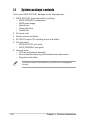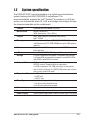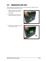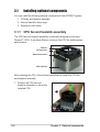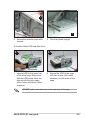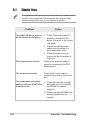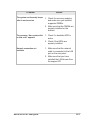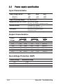
1
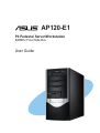
AP120-E1
P4 Pedestal Server/Workstation
800MHz Front Side Bus
User Guide
E1502
First Edition V1
March 2004
Copyright © 2004 ASUSTeK COMPUTER INC. All Rights Reserved.
No part of this manual, including the products and software described in it, may be
reproduced, transmitted, transcribed, stored in a retrieval system, or translated into any
language in any form or by any means, except documentation kept by the purchaser for
backup purposes, without the express written permission of ASUSTeK COMPUTER INC.
(“ASUS”).
ASUS provides this manual “as is” without warranty of any kind, either express or implied,
including but not limited to the implied warranties or conditions of merchantability or fitness
for a particular purpose. In no event shall ASUS, its directors, officers, employees, or agents
be liable for any indirect, special, incidental, or consequential damages (including damages
for loss of profits, loss of business, loss of use or data, interruption of business and the like),
even if ASUS has been advised of the possibility of such damages arising from any defect or
error in this manual or product.
Specifications and information contained in this manual ae furnished for informational use
only, and are subject to change at any time without notice, and should not be construed as a
commitment by ASUS. ASUS assumes no responsibility or liability for any errors or
inaccuracies that may appear in this manual, including the products and software described
in it.
Product warranty or service will not be extended if: (1) the product is repaired, modified or
altered, unless such repair, modification of alteration is authorized in writing by ASUS; or (2)
the serial number of the product is defaced or missing.
Products and corporate names appearing in this manual may or may not be registered
trademarks or copyrights of their respective companies, and are used only for identification or
explanation and to the owners’ benefit, without intent to infringe.
ii
Contents
Contents ......................................................................................... iii
Safety information .......................................................................... vi
About this guide ............................................................................ viii
ASUS contact information ............................................................... x
Chapter 1: Product introduction
1.1
1.2
1.3
1.4
1.5
1.6
System package contents .................................................. 1-2
System specifications ......................................................... 1-3
Front panel features ........................................................... 1-4
LED information .................................................................. 1-5
Rear panel features ............................................................ 1-5
Internal features ................................................................. 1-6
Chapter 2: Hardware setup
2.1
2.2
2.3
2.4
Preparation ......................................................................... 2-2
Removing the side cover .................................................... 2-2
Motherboard information .................................................... 2-4
Installing a Central Processing Unit (CPU) ........................ 2-5
2.4.1 Overview ................................................................ 2-5
2.4.2 CPU installation ..................................................... 2-6
2.5 Installing memory modules ................................................. 2-8
2.5.1 Memory configurations .......................................... 2-8
2.5.2 DIMM installation ................................................... 2-9
2.5.3 Removing a DIMM ................................................. 2-9
2.6 Installing a hard disk drive ................................................ 2-10
2.6.1 Qualified hard disk drives .................................... 2-10
2.6.2 Hard disk drive installation ....................................2-11
2.7 Installing 5.25-inch drives ................................................. 2-13
2.7.1 Removing the front panel cover ........................... 2-13
2.7.2 Installing additional optical drive(s) ...................... 2-15
2.8 Installing expansion cards ................................................ 2-17
2.9 Removing components ..................................................... 2-18
2.9.1 Removing the floppy disk drive ............................ 2-18
2.9.2 Removing the chassis fan .................................... 2-19
2.10 Connecting cables ............................................................ 2-20
2.11 Replacing the side cover .................................................. 2-21
iii
Contents
Chapter 3: Installation options
3.1
Installing optional components ........................................... 3-2
3.1.1 CPU fan and heatsink assembly ............................ 3-2
3.1.2 Second hard disk drive cage ................................. 3-4
3.1.3 Expansion card holder ........................................... 3-7
Appendix
A.1 Simple fixes ........................................................................ A-2
A.2 Power supply specification ................................................. A-4
iv
Notices
Federal Communications Commission Statement
This device complies with FCC Rules Part 15. Operation is subject to the
following two conditions:
• This device may not cause harmful interference, and
• This device must accept any interference received including interference
that may cause undesired operation.
This equipment has been tested and found to comply with the limits for a
Class B digital device, pursuant to Part 15 of the FCC Rules. These limits
are designed to provide reasonable protection against harmful interference
in a residential installation. This equipment generates, uses and can
radiate radio frequency energy and, if not installed and used in
accordance with manufacturer’s instructions, may cause harmful
interference to radio communications. However, there is no guarantee that
interference will not occur in a particular installation. If this equipment does
cause harmful interference to radio or television reception, which can be
determined by turning the equipment off and on, the user is encouraged to
try to correct the interference by one or more of the following measures:
• Reorient or relocate the receiving antenna.
• Increase the separation between the equipment and receiver.
• Connect the equipment to an outlet on a circuit different from that to
which the receiver is connected.
• Consult the dealer or an experienced radio/TV technician for help.
WARNING! The use of shielded cables for connection of the monitor
to the graphics card is required to assure compliance with FCC
regulations. Changes or modifications to this unit not expressly
approved by the party responsible for compliance could void the user’s
authority to operate this equipment.
Canadian Department of Communications Statement
This digital apparatus does not exceed the Class B limits for radio noise
emissions from digital apparatus set out in the Radio Interference
Regulations of the Canadian Department of Communications.
This class B digital apparatus complies with Canadian ICES-003.
v
Safety information
Electrical Safety
•
Before installing or removing signal cables, ensure that the power
cables for the system unit and all attached devices are unplugged.
•
To prevent electrical shock hazard, disconnect the power cable from
the electrical outlet before relocating the system.
•
When adding or removing any additional devices to or from the
system, ensure that the power cables for the devices are unplugged
before the signal cables are connected. If possible, disconnect all
power cables from the existing system before you add a device.
•
If the power supply is broken, do not try to fix it by yourself. Contact a
qualified service technician or your dealer.
Operation Safety
•
Any mechanical operation on this server/workstation must be
conducted by certified or experienced engineers.
•
Before operating the server/workstation, carefully read all the manuals
included with the server/workstation package.
•
Before using the server/workstation, make sure all cables are correctly
connected and the power cables are not damaged. If any damage is
detected, contact your dealer as soon as possible.
•
To avoid short circuits, keep paper clips, screws, and staples away
from connectors, slots, sockets and circuitry.
•
Avoid dust, humidity, and temperature extremes. Place the server/
workstation on a stable surface.
Caution!
This product is equipped with a three-wire power cable and plug for the
user’s safety. Use the power cable with a properly grounded electrical
outlet to avoid electrical shock.
vi
Safety information
Lithium-Ion Battery Warning
CAUTION! Danger of explosion if battery is incorrectly
replaced. Replace only with the same or equivalent type
recommended by the manufacturer. Dispose of used batteries
according to the manufacturer’s instructions.
CD-ROM Drive Safety Warning
CLASS 1 LASER PRODUCT
•
Electrical hazard, do not remove chassis cover.
•
This equipment is to be serviced by a trained
personnel only.
vii
About this guide
Audience
This user guide is intended for system integrators, and experienced users
with at least basic knowledge of configuring a server/workstation.
Contents
This guide contains the following parts:
1. Chapter 1: Product Introduction
This chapter describes the general features of the AP120-E1
server/workstation. It includes sections on front panel and rear panel
specifications.
2. Chapter 2: Hardware setup
This chapter lists the hardware setup procedures that you have to
perform when installing or removing system components.
3. Chapter 3: Installation options
This chapter provides information on installing and/or removing
optional system components.
4. Appendix
This appendix lists the common problems that you may encounter
while using the AP120-E1 server/workstation. It lists the possible
causes of the problems and offers solutions. You may refer to this part
and try to solve simple problems before calling customer support. The
appendix also contains the power supply specification for your
reference.
viii
Conventions
To make sure that you perform certain tasks properly, take note of the
following symbols used throughout this manual.
WARNING: Information to prevent injury to yourself when trying to
complete a task.
CAUTION: Information to prevent damage to the components when
trying to complete a task.
IMPORTANT: Information that you MUST follow to complete a task.
NOTE: Tips and information to aid in completing a task.
References
Refer to the following sources for additional information and for product
and software updates.
1. ASUS P4P800S-E motherboard user guide
This guide contains detailed information on the P4P800S-E
motherboard.
2. ASUS websites
The ASUS websites worldwide provide updated information on ASUS
hardware and software products. See the ASUS contact information on
the next page.
3. Optional documentation
Your product package may include optional documentations such as
CD-ROM manual, warranty flyers, and others that may have been
added by your dealer. These documents are not part of the standard
server/workstation package.
ix
ASUS contact information
ASUSTeK COMPUTER INC. (Asia-Pacific)
Address
Telephone
Web site
150 Li-Te Road, Peitou, Taipei, Taiwan 112
+886-2-2894-3447
www.asus.com.tw
Technical Support
Telephone
(MB/Component)
(Notebook)
(Server/PC)
(Networking)
Support fax
+886-2-2890-7121 (English)
+886-2-2890-7122 (English)
+886-2-2890-7123 (English)
+886-2-2890-7902 (English)
+886-2-2890-7698
ASUS COMPUTER INTERNATIONAL (America)
Address
Fax
E-mail
Web site
44370 Nobel Drive, Fremont, CA 94538, USA
+1-510-608-4555
[email protected]
usa.asus.com
Technical Support
Telephone
(General)
(Notebook)
Support fax
Support e-mail
+1-502-995-0883
+1-510-739-3777
+1-502-933-8713
[email protected]
ASUS COMPUTER GmbH (Germany and Austria)
Address
Telephone
Fax
Online contact
Harkort Str. 25, D-40880 Ratingen, Germany
+49-2102-95990
+49-2102-959911
www.asuscom.de/sales
Technical Support
Telephone
Fax
Online support
Web site
+49-2102-95990
+49-2102-959911
www.asuscom.de/support
www.asuscom.de/news
ASUS COMPUTER (Middle East and North Africa)
Address
Telephone
Fax
Web site
x
P.O. Box 64133, Dubai, U.A.E.
+9714-283-1774
+9714-283-1775
www.ASUSarabia.com
This chapter describes the general
features of the server/workstation.
This part also describes the system
front and rear panels, LED
indications, and internal
components.
ASUS AP120-E1 user guide
Product introduction
Chapter 1
1.1
System package contents
Check your ASUS AP120-E1 package for the following items.
1. ASUS AP120-E1 server/workstation including:
• ASUS P4P800S-E motherboard
• 250W power supply
• Optical drive
• Floppy disk drive
• Chassis fan
2. AC power cord
3. System screws and labels
4. AP120-E1 support CD including drivers and utilities
5. Documentation
• ASUS AP120-E1 user guide
• ASUS P4P800S-E user guide
6. Optional items
• CPU fan and heatsink assembly
• Second hard disk drive cage with retention base and screws
• Expansion card holder
Contact your dealer immediately if any of the items is damaged or
missing.
1-2
Chapter 1: Product introduction
1.2
System specification
The ASUS AP120-E1 server/workstation is a stylish server/workstation
system featuring the ASUS P4P800S-E motherboard. The
server/workstation supports the Intel® Pentium® 4 processor in a 478-pin
socket, and includes the latest I/O, LAN, and storage technologies through
the chipsets embedded on the motherboard.
Chassis
Pedestal with front panel I/O ports
Motherboard
ASUS P4P800S-E
(ATX form factor: 12in x 9.6in)
Chipset
Intel® 848P Memory Controller Hub (MCH)
Intel® ICH5R
Memory
Supports three 184-pin DDR PC3200/27002100
unbuffered non-ECC DDR DIMMs for up to 2GB system
memory
Processor
Supports Intel® Prescott processor with 800MHz
front side bus
LAN
Intel® CSA 82547E1 1000 Gigabit Ethernet controller
Storage
2 x IDE connectors to support 4 UltraDMA100 devices
2 x Serial ATA connectors to support 2 serial ATA HDDs
with RAID 0 and RAID1 function
Onboard I/O
PS/2 mouse/keyboard port, parallel port, serial port,
S/PDIF out port, floppy disk drive connector,
3 x IDE connectors, 6 x USB ports (four in rear panel,
two in front), LAN port, 2 x IEEE 1394 ports (one in front,
one in rear), audio I/O ports
Expansion Slots
5 x PCI slots
1 x AGP slot
1 x Wi-Fi slot
Drive Bays
1 x 3.5-inch floppy disk drive bay
1 x 3.5-inch hard disk drive bay
4 x 5.25-inch optical drive bays
Chassis fan
9cm chassis fan
Hardware Monitors Voltage, temperature, and fan speed monitoring
Power Supply
250W power supply with 20-pin ATX and 4-pin 12V plugs
ASUS AP120-E1 user guide
1-3
1.3
Front panel features
The AP120-E1 chassis displays a black stylish front panel.
The power button, LED indicators,
optical, and floppy drives are located on
the front panel. Flip the front panel I/O
ports cover to access the front panel
USB, IEEE 1394, and audio I/O ports.
Front panel I/O
ports cover
Optical drive
Empty 5.25-inch bays
Floppy disk drive
USB ports
Line In port
1-4
HDD LED
Power button and LED
Reset button
IEEE 1394 port
Line Out port
Chapter 1: Product introduction
1.4
LED information
The AP120-E1 comes with two LED indicators. Refer to the picture for the
LED location and the table below for LED description.
LED
Display
Description
Drive Activity LED
Blinking
Read/write data into the HDD
Power LED
ON
Blinking
System power ON
Suspend mode
1.5
Icon
Rear panel features
The rear panel includes a slot for the motherboard rear I/O ports, seven
full-length expansion slots, chassis cover locks, a vent for the system fan,
and the power supply unit.
Power connector
Voltage selector
P/S2 mouse port
S/PDIF Out port
Parallel port
Serial port
IEEE 1394 port
USB ports
Microphone port
Line In port
Power suppy unit
PS/2 keyboard port
9cm chassis fan
Gigabit LAN port
Line Out port
AGP expansion slot
PCI expansion slots
Side cover locking lever
Wi-Fi expansion slot
ASUS AP120-E1 user guide
1-5
1.6
Internal features
The AP120-E1 chassis includes the basic components as shown.
6
1
7
3
2
8
4
5
11
9
12
10
13
14
1.
2.
3.
4.
5.
6.
7.
Power supply
9cm chassis fan
CPU socket (under the CPU fan)
DDR DIMM sockets
IDE connectors
Optical drive
Empty 5.25-inch drive bays
8. FDD bay
9. Detachable HDD cage
10. Serial ATA connectors
11. ASUS P4P800S-E motherboard
12. AGP slot
13. PCI slots
14. Wi-Fi slot
The CPU fan and heatswink assembly and the hard disk drives are
purchased separately.
1-6
Chapter 1: Product introduction
Chapter 2
Hardware setup
This chapter lists the hardware
setup procedures that you have to
perform when installing or
removing system components.
ASUS AP120-E1 user guide
2.1
Preparation
Basic components to install
You need to install the following components to the AP120-E1
server/workstation.
1.
2.
3.
4.
5.
Central processing unit (CPU)
Dual Inline Memory Module(s) (DIMMs)
Hard disk drive
5.25-inch drive(s)
Expansion card(s)
Tool
You need a Philips (cross) screw driver to install some system components.
2.2
Removing the side cover
To remove the side cover:
1
1
2
1. Locate the two side cover
locks.
2-2
2. Press the side cover locks
outward, then pull the side
cover toward the rear panel for
about one-half inch.
Chapter 2: Hardware setup
4. Move the side cover to the
direction of the arrow.
5. Lift the side cover, then set
aside.
4
5
Viewing the internal structure
Without the side cover, the internal structure and installed components of
the barebone server/workstation appear as shown in the following picture.
Perform the procedures in the succeeding sections to install the CPU,
system memory, disk drives, and expansion cards.
ASUS AP120-E1 user guide
2-3
2.3
Motherboard information
The AP120-E1 comes with the ASUS P4P800S-E motherboard that uses
the ATX form factor measuring 12 inches x 9.6 inches (30.5 x 24.5 cm).
Make sure to unplug the power cord before installing or removing the
motherboard. Failure to do so may cause you physical injury and may
damage motherboard components.
The motherboard is secured to the chassis by ten screws as indicated by
circles in the illustration below.
Refer to the motherboard user guide for detailed information on the
motherboard.
2-4
Chapter 2: Hardware setup
2.4
Installing a Central Processing Unit (CPU)
2.4.1 Overview
The motherboard comes with a surface mount 478-pin Zero Insertion
Force (ZIF) socket. The socket is designed for the Intel® Pentium® 4
Prescott processor in the 478-pin package with 512KB L2 cache. The
motherboard supports 800/533/400MHz front side bus (FSB), and allows
data transfer rates of up to 6.4GB/s.
Note in the illustration that the CPU has a gold triangular mark on one
corner. This mark indicates the processor Pin 1 that should match a
specific corner of the CPU socket.
Gold Arrow
®
P4P800S-E
P4P800S-E Socket 478
Incorrect installation of the CPU into the socket may bend the pins and
severely damage the CPU!
ASUS AP120-E1 user guide
2-5
2.4.2 CPU installation
Follow these steps to install a CPU.
1. Locate the 478-pin ZIF socket on
the motherboard.
2. Unlock the socket by pressing the
lever sideways, then lift it up to a
90°-100° angle.
Socket Lever
90 - 100
Make sure that the socket lever
is lifted up to 90°-100° angle,
otherwise the CPU does not fit
in completely.
3. Position the CPU above the socket
such that its marked corner
matches the base of the socket
lever.
4. Carefully insert the CPU into the
socket until it fits in place.
Gold Mark
The CPU fits only in one correct
orientation. DO NOT force the
CPU into the socket to prevent
bending the pins and damaging
the CPU!
5. When the CPU is in place, push
down the socket lever to secure the
CPU. The lever clicks on the side
tab to indicate that it is locked.
2-6
Chapter 2: Hardware setup
6. Install a CPU heatsink and fan following the instructions that came with
the heatsink package.
ASUS provides an Intel®-certified CPU fan and heatsink assembly as
an optional item for your AP120-E1 system. Refer to the “Installation
options” chapter for details.
7. Connect the CPU fan cable to the
CPU_FAN1 connector on the
motherboard.
CPU fan connector
(CPU_FAN1)
Don’t forget to connect the CPU fan connector! Hardware monitoring
errors may occur if you fail to plug this connector.
ASUS AP120-E1 user guide
2-7
2.5
Installing memory modules
104 Pins
80 Pins
The motherboard comes with three (3) Double Data Rate (DDR) Dual
Inline Memory Module (DIMM) sockets. These sockets support up to 3GB
system memory using 184-pin unbuffered non-ECC PC3200/2700/2100
DDR DIMMs. The following figure shows the location of the DDR DIMM
sockets.
®
DIMM3
P4P800S-E 184-Pin DDR DIMM Sockets
DIMM2
DIMM1
P4P800S-E
Obtain DDR DIMMs only from ASUS qualified vendors to ensure
system system stability. The DDR400 Qualified Vendors List (QVL) is
provided below. Visit http://www.asus.com/products/server/
RAMsupport.htm for the latest QVL.
2.5.1 Memory configurations
You may install 64MB, 128MB, 256MB, 512MB, and 1GB DDR DIMMs into
the DIMM sockets.
Table 1: Qualified DDR400 vendors list
This table lists the memory modules that have been tested and qualified
for use with this motherboard.
2-8
Size
Vendor
Part Number
Chip Brand
Chip Number
256MB
Apacer
77.10638.465
SAMSUNG
K4H560838D
256MB
Trancend
V58C2256804SAT75
Trancend
V58C2256804SAT75
512MB
Infineon
HYS64D64320GU-5-B
Infineon
HYB25D256800BT-5
512MB
Kingston
KVR333X64C25/512
Kingston
D3208DH1T-6
Chapter 2: Hardware setup
2.5.2 DIMM installation
Make sure to unplug the power supply before adding or removing
DIMMs or other system components. Failure to do so may cause
severe damage to both the motherboard and the components.
Follow these steps to install a DIMM.
DDR DIMM notch
1. Unlock a DIMM socket by pressing
the retaining clips outward.
2. Align a DIMM on the socket such
that the notch on the DIMM
matches the break on the socket.
A DDR DIMM is keyed with a
notch so that it fits in only one
direction. DO NOT force a
DIMM into a socket to avoid
damaging the DIMM.
Unlocked
retaining clip
3. Firmly insert the DIMM into the
socket until the retaining clips
snap back in place and the
DIMM is properly seated.
Locked retaining clip
2.5.3 Removing a DIMM
Follow these steps to remove a
DIMM.
1. Simultaneously press the
retaining clips outward to unlock
the DIMM.
Support the DIMM lightly with your fingers when pressing the retaining
clips. The DIMM might get damaged when it flips out with extra force.
2. Remove the DIMM from the socket.
ASUS AP120-E1 user guide
2-9
2.6
Installing a hard disk drive
The server/workstation system
supports one IDE/Serial ATA hard
disk drive through a detachable hard
disk drive cage.
You may purchase a second
hard disk drive cage to install
an additional HDD. Refer to
the next chapter for details.
Hard disk drive cage
Configure your hard disk drive as Master/Slave device before installing
it to the chassis. Refer to the HDD documentation on how to set the
drive as a Master/Slave device.
2.6.1 Qualified hard disk drives
The table below lists the hard disk drives tested and qualified for use with
this server/workstation.
Table 2: Qualified hard disk drive vendors list
Vender
2-10
Model
Interface
Speed
Capacity
Seagate
ST380021A
IDE
7200rpm
80GB
Seagate
ST3120023A
IDE
7200rpm
120GB
IBM/Hitachi
Deskstart IC35L090AVV207
IDE
7200rpm
80GB
Maxtor
MAXTOR/6Y80L0
IDE
7200rpm
80GB
IBM/Hitachi
Deskstart IC35L120AVV207
IDE
7200rpm
120GB
Maxtor
MAXTOR/6Y160L0
IDE
7200rpm
160GB
Seagate
ST3160023A
IDE
7200rpm
160GB
IBM/Hitachi
Deskstart IC35L180AVV207
IDE
7200rpm
180GB
Seagate
ST380013AS
SATA
7200rpm
80GB
Seagate
ST3120026AS
SATA
7200rpm
120GB
Seagate
ST3160023AS
SATA
7200rpm
160GB
Maxtor
6Y080M0
SATA
7200rpm
80GB
Maxtor
6Y120M0
SATA
7200rpm
120GB
Chapter 2: Hardware setup
2.6.2 Hard disk drive installation
The detachable hard disk drive cage can accommodate one IDE or
Serial ATA hard disk drive.
To install an IDE hard disk drive:
Configure your hard disk drive as Master/Slave device before installing
it to the drive cage. Refer to the HDD documentation on how to set the
drive as a Master/Slave device.
1
2
Screw holes
1. Press the HDD cage lock while
pulling the cage out from the
chassis. Place the HDD cage in
a flat surface.
2. Insert a HDD to the upper bay
of the cage. Make sure that the
HDD screw holes are aligned
with the HDD cage screw holes
(with black rubber stoppers).
DO NOT install a hard disk drive to the lower bay of the cage.
3
4
3. Secure the HDD to the cage
with two screws (with metal
washers) on both sides of the
cage.
ASUS AP120-E1 user guide
4. Re-install the HDD cage to the
chassis. Align the HDD cage
and bay assembly rails, then
carefully push the HDD cage
until it is flushed to the chassis.
2-11
5
6
5. Connect a 40-pin IDE cable to
the IDE connector at the back
of the drive.
6. Connect a 4-pin power plug
from the power supply unit to
the power connector at the
back of the drive.
Refer to the motherboard user guide the correct IDE cable before
connecting anIDE cable to the hard disk drive.
To install a Serial ATA hard disk drive:
1. Follow steps 1-4 of the previous section.
2. Connect one end of the supplied 7-pin SATA cable to the SATA
connector at the back of the drive, then connect the other end to a
SATA connector on the motherboard. See page 3-6 for the location of
the SATA connectors.
3. For Serial ATA HDDs with a 4-pin power connector:
Connect a 4-pin (female) power plug from the power supply unit (PSU)
to the 4-pin (male) power connector at the back of the drive.
For Serial ATA HDDs without a 4-pin power connector:
Use a SATA power cable.
Connect a 4-pin plug (female)
from the PSU to the 4-pin (male)
plug of the SATA power cable.
Connect the 15-pin SATA power
15-pin
plug to the power connector at
the back of the drive.
4-pin (male)
Serial ATA power cable
2-12
Chapter 2: Hardware setup
2.7
Installing 5.25-inch drives
Make sure to unplug the power cable before installing or removing any
system components. Failure to do so may cause severe damage to the
motherboard and other system components!
The system comes with four
5.25-inch drive bays located on the
upper front part of the chassis. An
optical drive that comes standard
with the system package occupies
the uppermost bay (labeled 1). The
three lower bays (labeled 2, 3, and 4)
are available for additional 5.25-inch
optical, zip, or floppy disk drives.
1
2
3
4
You must remove the front panel cover before installing a 5.25-inch
drive(s).
2.7.1 Removing the front panel cover
To remove the front panel cover:
1
2
1. Locate and remove two screws
that secure the left side cover
to the chassis. Keep the screw
for later use.
ASUS AP120-E1 user guide
2. Slightly pull the cover toward
the direction of the rear panel
until it disengages from the
chassis. Set the cover aside.
2-13
3. Press the front panel cover
hook inward until it detaches
from the chassis hole.
3
4. On the other side of the
system, locate three front panel
cover hooks. Press the hooks
inward until the front panel
cover detaches from the
chassis.
4
5. Carefully remove the front
panel cover, then set aside.
5
2-14
Chapter 2: Hardware setup
2.7.2 Installing additional optical drive(s)
Configure your optical drive as Master/Slave device before installing it
to the drive bay. Refer to the optical drive documentation for details.
To install an additional optical drive(s):
1
2
1
1. Select the drive bay you intend
to use. Push the knock down
metal cover in and out of the
chassis until it is removed.
2. Carefully insert the drive to the
bay, then push it inward until it
is flushed to the chassis front
panel.
Screw holes
3
3. Align the optical drive and bay
screw holes.
ASUS AP120-E1 user guide
4
4. Secure the drive with two
screws on both sides of the
bay.
2-15
5
6
5. Connect a 40-pin IDE cable
(from the first optical drive) to
the IDE connector on the drive.
7
7. Remove the front panel bay
cover opposite the drive bay
you used by pressing the
hooks inward.
Follow the same procedures
when installing additional
optical drives.
2-16
6. Connect a 4-pin power plug
from the power supply unit to
the drive power connector.
8
8. Re-install the front panel and
side covers when done.
Chapter 2: Hardware setup
2.8
Installing expansion cards
The system comes with five PCI slots, one AGP slot, and an ASUS
proprietary Wi-Fi slot for installation of expansion cards.
Make sure to unplug the power supply before installing or removing an
expansion card(s). Failure to do so may cause severe damage to both
the motherboard and the components.
To install an expansion card:
1. Before installing the expansion card, read the documentation that
came with it and make the necessary hardware settings for the card.
2. Lay the system on its side on a flat, stable surface.
3. Remove the metal bracket
3
opposite the slot that you intend
to use. Keep the metal bracket
screw for later use.
4. Align the card connector with the
slot, then press firmly until the
card is completely seated on the
slot.
5. Secure the card with the metal
bracket screw you removed
earlier.
ASUS AP120-E1 user guide
4
5
2-17
2.9
Removing components
You may need to remove previously installed system components when
installing or removing other system components, or when replacing a
defective component. This section tells how to remove the following
components:
1. Floppy disk drive (FDD)
2. System fan
2.9.1 Removing the floppy disk drive
To remove the FDD:
1. Disconnect the FDD power plug and signal cable.
3
2
2. Unlock the FDD bay by moving
the drive bay lock toward the
direction of the front panel.
3. Carefully pull the FDD from the
chassis. Set the FDD aside.
To install a floppy disk drive:
1. Insert the drive to the bay until it
is flushed to the chassis front
panel.
2. Align the FDD screw hole with
the drive bay lock pin.
2-18
1
Chapter 2: Hardware setup
3. Move the drive bay lock toward
the rear panel to secure the drive.
4. Attach the FDD power and signal
cables to the connectors at the
back of the drive.
3
2.9.2 Removing the chassis fan
To remove the chassis fan:
1. Disconnect the chassis fan cable from the CHA_FAN1 connector on
the motherboard.
2. Locate and remove four chassis
2
fan screws at the rear panel.
Keep the screws for later use.
Hold the chassis fan with one
hand while removing the
chassis fan screws.
3. Remove the chassis fan, then set
aside.
ASUS AP120-E1 user guide
3
2-19
2.10 Connecting cables
The AP120-E1 chassis includes the power and signal cables that you
need to connect to the motherboard, storage drives, and other devices
that you intend to install.
Most of the cables for the chassis kit are already connected upon
shipment. When installing system devices and connecting cables,
make sure that all cables are routed properly for better system stability
and performance. Refer to the picture below when arranging cables.
3
1
2
9
8
6
4
5
7
Standard cables connected to the motherboard
1.
2.
3.
4.
5.
4-pin ATX 12V power plug
20-pin ATX power plug
Floppy disk drive ribbon cable
Front panel audio cable
Front panel IEEE 1394 cable
6.
7.
8.
9.
Front panel USB cable
Panel cable
System fan cable
Primary and secondary IDE
cable
Refer to the motherboard user guide for detailed information on
motherboard connectors.
2-20
Chapter 2: Hardware setup
2.11 Replacing the side cover
After installing all components and re-connecting cables, replace the side
cover by following these instructions.
1. Match the side cover hooks to
the chassis rail on the side of
the chassis.
2. Fit the side cover the cover
toward the chassis until it fits.
2
1
3. Slide the cover toward the front
until it snaps in place.
3
ASUS AP120-E1 user guide
2-21
2-22
Chapter 2: Hardware setup
This chapter provides information
on optional and removable
components you may install to or
remove from the system.
ASUS AP120-E1 user guide
Installation options
Chapter 3
3.1
Installing optional components
You may install the following optional components to the AP120-E1 system.
1. CPU fan and heatsink assembly
2. Second hard disk drive cage
3. Expansion card holder
3.1.1 CPU fan and heatsink assembly
The CPU fan and heatsink assembly is specially designed for the Intel®
Pentium® 4 CPU. It provides efficient cooling to the CPU for stable system
performance.
CPU fan
Locking lever
Retention bracket
CPU heatsink
After installing the CPU, follow these instructions to install the CPU fan
and heatsink assembly.
1. Position the CPU fan and
heatsink assembly on top of the
installed CPU.
1
3-2
Chapter 3: Optional components
•
The retention module base is already installed on the motherboard
upon purchase.
•
Do not remove the retention module base when installing the CPU
or installing other system components.
2. Align the retention bracket with
the rails on the side of the CPU
fan.
3. Attach the retention bracket hook
into the retention module hole.
2
3
4. Carefully press down the locking
lever on the other side of the
retention bracket.
5. Attach the locking lever hook into
the retention module hole to
secure the fan and heatsink
assembly in place.
6. Follow steps 2 to 5 to re-install
the second retention bracket.
4
5
The illustrations are for reference only and may not exactly match the
actual component.
ASUS AP120-E1 user guide
3-3
3.1.2 Second hard disk drive cage
The second hard disk drive cage
accommodates one IDE or Serial
ATA hard disk drive.
Second hard disk
drive cage
HDD cage
retention base
Rails
Hooks
You need to install the retention base to the chassis before installing the
second HDD cage.
To install the retention base:
1. Lay the system on its side on a flat, stable surface.
2
3
2. Locate two retention base
holes on the chassis floor.
3-4
3. Insert the retention base hooks
to the holes until they fit in
place.
Chapter 3: Optional components
4
5
4. Secure the retention base with
a screw.
5. Turn the system upright.
To install a Serial ATA hard disk drive:
1
2
Screw holes
1. Insert a HDD to the lower bay
of the drive cage. Make sure
that the HDD screw holes are
aligned with the drive cage
screw holes (with black rubber
stoppers).
2. Secure the HDD to the cage
with two screws (with metal
washers) on both sides of the
cage.
DO NOT install a hard disk drive to the upper bay of the cage.
ASUS AP120-E1 user guide
3-5
3
4
3. Connect one end of the 7-pin
Serial ATA cable to the
connector at the back of the
drive(s).
4. Align the drive cage and
retention base rails, then
slightly push the cage until it
clicks in place
5
6
5. Connect the other end of the
Serial ATA cable to the SATA
connectors on the
motherboard.
6. Connect a 4-pin power plug
from the power supply unit to
the power connector at the
back of the drive(s).
Use a Serial ATA power cable and adapter for Serial ATA HDD(s)
without a 4-pin power connector.
3-6
Chapter 3: Optional components
3.1.3 Expansion card holder
The expansion card holder provides support for long and heavy PCI and
AGP cards.
Install all necessary expansion cards before installing the expansion
card holder.
Grooves
Locking lever
Assembly
Card holders
Adjusting slots
Locking screw
The expansion card holder comes with a retention bracket to keep the
expansion card holder in place.
To install the retention bracket:
1. Lay the system on its side on a flat, stable surface.
2. Locate two retention bracket
screw holes on the chassis floor.
3. Place the retention bracket
over the chassis floor screw
holes, then secure the bracket
with two screws.
4. Turn the chassis upright.
ASUS AP120-E1 user guide
2
3
3-7
To install the expansion card holder:
1. Insert the expansion card
holder locking screw to the
retention bracket notch, as
shown.
1
2. Turn the expansion card holder
upright.
3. Press the locking lever, then
insert the hooks to the chassis
holes.
3
2
4. Secure the expansion card
holder with one screw.
4
3-8
Chapter 3: Optional components
To hold long expansion cards:
1. Place the card holder at level with the expansion card.
The smaller card holder is for
long AGP cards while the
other card holders are for
long PCI cards.
2
2. Loosen the screw(s) to adjust the
card holder forward or sideward
until its groove fits the edge of the
expansion card.
3. Fasten the card holder screw(s).
4. Follow the same steps in holding
other long expansion.
ASUS AP120-E1 user guide
3
3-9
3-10
Chapter 3: Optional components
Appendix
Appendix
This appendix lists the common
problems that you may encounter
while using the server. It lists the
possible causes of the problems
and offers solutions. You may refer
to this part and try to solve simple
problems before calling customer
support. The appendix also
contains the power supply unit
specifications for your reference.
ASUS AP120-E1 user guide
A-1
A.1
Simple fixes
Some problems that you may encounter are not due to defects on the
system or the components. These problems only requires simple
troubleshooting actions that you can perform by yourself.
Problem
A-2
Action
The power LED on the server or
on the monitor do not light up
1. Check if the power cable is
properly connected to the
power connector in the system
rear panel.
2. Make sure that the power
cables are connected to a
grounded power outlet.
3. Press the power button to
make sure that the system is
turned on.
The keyboard does not work
Check if the keyboard cable is
properly connected to the PS/2
keyboard port.
The mouse does not work
Check if the mouse cable is
properly connected to the mouse
port.
The system does not perform
power-on self tests (POST) after
it was turned on
1. Check the memory modules
and make sure you installed
the DIMMs the system
supports.
2. Make sure that the DIMMs are
properly installed on the
sockets.
Appendix: Troubleshooting
Problem
Action
The system continuously beeps
after it was turned on
1. Check the memory modules
and make sure you installed
supported DIMMs.
2. Make sure that the DIMMs are
properly installed on the
sockets.
The message “Non-system disk
or disk error” appears
1. Check if a bootable HDD is
active.
2. Check if the HDDs are
properly installed.
Network connection not
available
1. Make sure that the network
cable is connected to the LAN
port on the rear panel.
2. Make sure that you have
installed the LAN drivers from
the support CD.
ASUS AP120-E1 user guide
A-3
A.2
Power supply specification
Input Characteristics
Input Voltage Range
Min
Nom
Max
Range 1
90V
115V
135V
Range 2
180V
230V
265V
Input Frequency Range
47 Hz to 63 Hz
Maximum Input ac Current 9A max at 115Vac
5A max. at 230Vac, maximum load
Inrush Current
70A max. at 115Vac,
full load cold start at 25°C
Efficiency
68% min. at nominal input,
maximum load
Output Characteristics
Output
Load Range
Regulation
Ripple
Voltage
Min
Max
Min
Max
Max
+5V
1.5A
25.0A
-5%
+5%
50mVp-p
+12V
0.2A
8.0A
-5%
+5%
120mVp-p
-12V
0A
0.8A
-10%
+10%
150mVp-p
-5V
0A
0.5A
-5%
+5%
100mVp-p
+5Vsb
0A
2.0A
-5%
+5%
100mVp-p
+3V3
0A
14.0A
-5%
+5%
50mVp-p
Over-Voltage Protection (OVP)
Output Voltage
A-4
Maximum Voltage
+5V
6.5V
+12V
15.6V
+3.3V
4.3V
Appendix: Troubleshooting