1
Evaluate: MAX1416/MAX1415/MX7705
MAX1416 Evaluation Kit/Evaluation System
Component Suppliers
SUPPLIER
PHONE
FAX
WEBSITE
Taiyo Yuden
800-348-2496
847-925-0899
www.t-yuden.com
TDK Corp.
847-803-6100
847-390-4405
www.component.tdk.com
Note: Indicate that you are using the MAX1416 when contacting these component suppliers.
Quick Start
Recommended Equipment (USB Port/PC
Connection Option)
Before beginning, the following equipment is needed:
• MAX1416 EV system:
MAX1416 EV kit
68HC16MODULE-DIP
USBTO232 (USB cable included)
• DC power supply, +7VDC to +12VDC at 0.25A
• DC power supply, +5VDC
• A user-supplied Windows 2000/XP computer with an
available USB port to connect to the USBTO232
board
Note: In the following sections, software-related items
are identified by bolding. Text in bold refers to items
directly from the EV kit software. Text in bold and
underlined refers to items from the Windows 2000/XP
operating system.
Procedure
The MAX1416 EV kit is fully assembled and tested.
Follow the steps below to verify board operation.
Caution: Do not turn on the power until all connections are completed.
1) Visit the Maxim website (www.maxim-ic.com) to
download the latest version of the USBTO232 User
Guide. Follow the steps in the USBTO232 User Guide
Quick Start section and return to step 2 of this Quick
Start section when finished.
2) Ensure that jumpers JU1, JU2, and JU4 are closed
and that jumper JU3 is in the 1-2 position (see Table
1 for jumper settings).
3) Carefully connect the boards by aligning the 40-pin
header of the MAX1416 EV kit with the 40-pin connector of the 68HC16MODULE-DIP module. Gently
press them together. The two boards should be flush
against one another.
4) Connect the +5VDC power source to the MAX1416
EV kit at terminal block TB1. Observe the polarity
marked on the board.
2
5) Connect the +7VDC to +20VDC power source to the
µC module at the terminal block located next to the
ON/OFF switch, along the top-edge of the µC module. Observe the polarity marked on the board.
6) Connect the USBTO232 board to the
68HC16MODULE-DIP module if you have not done
so already.
7) The MAX1416 EV kit software should have already
been downloaded and installed in the USBTO232
Quick Start.
8) Start the MAX1416 program by opening its icon in the
Start | Programs menu.
9) Turn on the power supplies and slide SW1 to the ON
position on the 68HC16MODULE-DIP module. Press
the OK button to automatically connect and download the KIT1416.C16 file to the module.
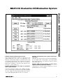
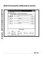
10) When the main window appears (Figure 1), click
Initialize and then Calibrate.
11) Apply input signals between AIN1+ and AIN1-. Tie
the unused analog input (AIN2+ and AIN2-) to GND.
Click Read or check Auto Read. Observe the code
and voltage readout on the screen.
Recommended Equipment (RS-232-to-COM
Port/PC Connection Option)
Before beginning, the following equipment is needed:
• MAX1416 EV system:
MAX1416 EV kit
68HC16MODULE-DIP
• DC power supply, +7VDC to +12VDC at 0.25A
• DC power supply, +5VDC
• A user-supplied Windows 98/2000/XP computer with
an available serial (COM) port
• 9-pin I/O extension cable
Note: In the following sections, software-related items are
identified by bolding. Text in bold refers to items directly
from the EV kit software. Text in bold and underlined
refers to items from the Windows 98/2000/XP operating
system.
_______________________________________________________________________________________